1
INSTRUCTIONS FOR INSTALLATION AND SERVICING
TURBOmax Plus 824/2 E, 828/2 E
Wall hung room sealed fan assisted combination boilers
THERMOcompact 615/2 E, 620/2 E, 624/2 E, 628/2 E
Wall hung room sealed fan assisted system boilers
The code of practice for the installation,
commissioning & servicing of central heating systems
TABLE OF CONTENTS
Contents included with boiler (TURBOmax Plus) . . . . . . . .4
Contents included with boiler (THERMOcompact) . . . . . . .5
Introduction
General Information . . . . . . . . . . . . . . . . . . . . . . . . . .6
General notes . . . . . . . . . . . . . . . . . . . . . . . . . . . . . . .6
EC designation . . . . . . . . . . . . . . . . . . . . . . . . . . . . . .6
Boiler Specification
Technical data . . . . . . . . . . . . . . . .
Boiler connections (TURBOmax Plus) . .
Boiler connections (THERMOcompact)
Functional diagram (TURBOmax Plus) .
Functional diagram (THERMOcompact)
.
.
.
.
.
.
.
.
.
.
.
.
.
.
.
.
.
.
.
.
.
.
.
.
.
.
.
.
.
.
.
.
.
.
.
.
.
.
.
.
.
.
.
.
.
.
.
.
.
.
.
.
.
.
.
.
.
.
.
.
. .7
. .8
. .8
. .9
.10
General Requirements
Related documents . . . . . . . . . . . . . .
Boiler location . . . . . . . . . . . . . . . . .
Gas supply . . . . . . . . . . . . . . . . . . .
Flue system . . . . . . . . . . . . . . . . . . .
Top outlet flue system . . . . . . . .
Rear outlet flue system . . . . . . . .
Extended top outlet flue system . .
Flue termination . . . . . . . . . . . .
Air supply . . . . . . . . . . . . . . . . . . . .
Cupboard or compartment ventilation . .
Electrical supply . . . . . . . . . . . . . . . .
Guide to system requirements . . . . . . .
Water circulation system . . . . . .
Filling and make up . . . . . . . . .
Pressure relief valve . . . . . . . . .
Pressure gauge . . . . . . . . . . . .
Expansion vessel . . . . . . . . . . .
Circulating pump . . . . . . . . . . .
System by-pass . . . . . . . . . . . . .
Venting . . . . . . . . . . . . . . . . . .
DHW expansion vessel accessory
.
.
.
.
.
.
.
.
.
.
.
.
.
.
.
.
.
.
.
.
.
.
.
.
.
.
.
.
.
.
.
.
.
.
.
.
.
.
.
.
.
.
.
.
.
.
.
.
.
.
.
.
.
.
.
.
.
.
.
.
.
.
.
.
.
.
.
.
.
.
.
.
.
.
.
.
.
.
.
.
.
.
.
.
.
.
.
.
.
.
.
.
.
.
.
.
.
.
.
.
.
.
.
.
.
.
.
.
.
.
.
.
.
.
.
.
.
.
.
.
.
.
.
.
.
.
.
.
.
.
.
.
.
.
.
.
.
.
.
.
.
.
.
.
.
.
.
.
.
.
.
.
.
.
.
.
.
.
.
.
.
.
.
.
.
.
.
.
.
.
.
.
.
.
.
.
.
.
.
.
.
.
.
.
.
.
.
.
.
.
.
.
.
.
.
.
.
.
.
.
.
.
.
.
.
.
.
.
.
.
.
.
.
.
.
.
.
.
.
.
.
.
.
.
.
.
.
.
.
.
.
.11
.12
.12
.13
.13
.13
.13
.14
.15
.15
.15
.16
.16
.16
.16
.16
.17
.18
.18
.18
.18
Boiler Installation Sequence
General . . . . . . . . . . . . . . . . . . . . . . . .
Preparation of boiler location . . . . .
Selecting position of boiler . . . . . . .
Using boiler template . . . . . . . . . . . . . . .
Fitting the boiler hanging bracket . . . . . . .
Install the flue system . . . . . . . . . . . . . . .
Fitting the boiler . . . . . . . . . . . . . . . . . .
Removing boiler casing . . . . . . . . . . . . .
Gas supply (TURBOmax Plus) . . . . . . . . .
Cold water mains inlet and hot water outlet
(TURBOmax Plus) . . . . . . . . . . . . . . . . .
Central heating flow and return pipework
(TURBOmax Plus) . . . . . . . . . . . . . . . . .
Gas supply (THERMOcompact) . . . . . . . .
Central heating flow and return pipework
(THERMOcompact) . . . . . . . . . . . . . . . .
Connection to a Vantage unvented cylinder
(THERMOcompact)
Connect the flue system to the boiler . . . . .
Electrical installation general requirements .
Connection to the main supply . . . . . . . .
Controls . . . . . . . . . . . . . . . . . . . . . . . .
Fit boiler casing . . . . . . . . . . . . . . . . . .
.
.
.
.
.
.
.
.
.
.
.
.
.
.
.
.
.
.
.
.
.
.
.
.
.
.
.
.
.
.
.
.
.
.
.
.
.
.
.
.
.
.
.
.
.
.
.
.
.
.
.
.
.
.
.
.
.
.
.
.
.
.
.
.
.
.
.
.
.
.
.
.
.
.
.
.
.
.
.
.
.
.19
.19
.19
.20
.21
.21
.21
.22
.23
THERMO
compact
TURBO
max
List of Contents
2
. . . . . . . . . .24
. . . . . . . . . .25
. . . . . . . . . .26
. . . . . . . . . .27
.
.
.
.
.
.
.
.
.
.
.
.
.
.
.
.
.
.
.
.
.
.
.
.
.
.
.
.
.
.
.
.
.
.
.
.
.
.
.
.
.
.
.
.
.
28
.28
.30
.31
.33
.38
TABLE OF CONTENTS
Preliminary electrical checks . . . . . . . . . . . . . . . . . . . .39
Gas supply . . . . . . . . . . . . . . . . . . . . . . . . . . . . . . .39
Cold water supply (TURBOmax Plus only) . . . . . . . . . . .39
Filling the heating system (TURBOmax Plus) . . . . . . . . . .40
Filling the heating system (THERMOcompact) . . . . . . . . .42
Initial system flush (`cold`) . . . . . . . . . . . . . . . . . . .41/43
Gas supply adjustments
(Commissioning Part II)
Gas inlet working pressure . . . . . . . . . . . . . . . . . . . . .44
Main burner pressure . . . . . . . . . . . . . . . . . . . . . . . . .45
Adjusting the central heating output (range rating) . . . . .46
Adjusting the ignition rate . . . . . . . . . . . . . . . . . . . . . .48
Adjusting to the maximum heat load (nominal load) . . . .49
Burner pressure and gas rate . . . . . . . . . . . . . . . . .50/51
Functional checks
(Commissioning Part III)
Functional checks . . . . . . . .
Functional check of operation
Adjusting pump speed . . . . .
Final system flush (hot) .
Handing over to the user . . .
Servicing
Initial inspection . . . . . . . . . . . . . . . . . . . . . . . . . . . .57
Cleaning the burner and primary heat exchanger . . . . . .58
Parts replacement
Safety instructions . . . . . . . . . . . . . .
Initial preparation . . . . . . . . . . . . . .
Burner . . . . . . . . . . . . . . . . . . . . . .
Electrodes . . . . . . . . . . . . . . . . . . .
Fan
......................
Gas valve . . . . . . . . . . . . . . . . . . .
Temperature sensors (NTCs) . . . . . . .
Main heat exchanger . . . . . . . . . . . .
Expansion vessel . . . . . . . . . . . . . . .
Electronic control board . . . . . . . . . .
Main transformer . . . . . . . . . . . . . .
Pump . . . . . . . . . . . . . . . . . . . . . .
Air pressure switch . . . . . . . . . . . . .
Automatic bypass . . . . . . . . . . . . . .
Pressure gauge . . . . . . . . . . . . . . . .
Diverter valve (TURBOmax Plus only) .
Aqua sensor (TURBOmax Plus only) . .
DHW heat exchanger (TURBOmax Plus
Pressure relief valve . . . . . . . . . . . . .
Checking functions . . . . . . . . . . . . .
....
....
....
....
....
....
....
....
....
....
....
....
....
....
....
....
....
only)
....
....
.
.
.
.
.
.
.
.
.
.
.
.
.
.
.
.
.
.
.
.
.
.
.
.
.
.
.
.
.
.
.
.
.
.
.
.
.
.
.
.
.
.
.
.
.
.
.
.
.
.
.
.
.
.
.
.
.
.
.
.
.
.
.
.
.
.
.
.
.
.
.
.
.
.
.
.
.
.
.
.
.
.
.
.
.
.
.
.
.
.
.
.
.
.
.
.
.
.
.
.
.
.
.
.
.
.
.
.
.
.
.
.
.
.
.
.
.
.
.
.
.
.
.
.
.
.
.
.
.
.
.
.
.
.
.
.
.
.
.
.
.
.
.
.
.
.
.
.
.
.
.
.
.
.
.
.
.
.
.
.
.59
.59
.60
.60
.61
.62
.63
.63
.64
.65
.65
.66
.66
.67
.67
.68
.68
.69
.69
.70
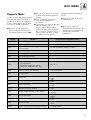
Fault Finding
Introduction . . . . . . . . . . . . .
Indicator lights . . . . . . . . . . .
Logical fault finding procedure
Status mode . . . . . . . . . . . . .
Diagnostic modes . . . . . . . . .
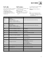
Fault codes . . . . . . . . . . . . .
Fault memory . . . . . . . . . . . .
Fault finding charts . . . . . . . .
.
.
.
.
.
.
.
.
.
.
.
.
.
.
.
.
.
.
.
.
.
.
.
.
.
.
.
.
.
.
.
.
.
.
.
.
.
.
.
.
.
.
.
.
.
.
.
.
.
.
.
.
.
.
.
.
.
.
.
.
.
.
.
.
.
.
.
.
.
.
.
.
.71
.72
.73
.74
.75
.77
.77
.78
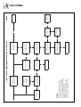
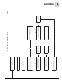
Diagrams
Functional flow diagrams . . . . . . . . . . . . . . . . . . . . . .85
Wiring diagrams . . . . . . . . . . . . . . . . . . . . . . . . . . . .87
Short parts list
Short parts list . . . . . . . . . . . . . . . . . . . . . . . . . . . . .89
TURBO
max
Commissioning Part I
. . . . . . . . . . . . . . . . . . .52
. . . . . . . . . . . . . . . .53/54
. . . . . . . . . . . . . . . . . . .55
. . . . . . . . . . . . . . . . . . .55
. . . . . . . . . . . . . . . . . . .56
.
.
.
.
.
.
.
.
.
.
.
.
.
.
.
.
.
.
.
.
.
.
.
.
.
.
.
.
.
.
.
.
.
.
.
.
.
.
.
.
.
.
.
.
.
.
.
.
.
.
.
.
.
.
.
.
.
.
.
.
.
.
.
.
3
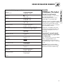
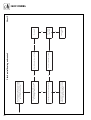
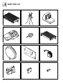
LIST OF CONTENTS
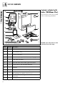
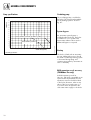
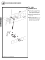
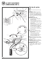
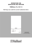
Contents included with
boiler (TURBOmax Plus)
TURBOmax Plus
12
1
Instructions for Installation
BEDIENUNGSANLEITUNG
11
Ensure that all contents are included
before commencing installation.
2
BEDIENUNGSANLEITUNG
BEDIENUNGSANLEITUNG
BEDIENUNGSANLEITUNG
11
BEDIENUNGSANLEITUNG
11
o
C
VRC-
o
C
VC
I
0
10
3
9
8
4
5
6
Fig. L.1: Items supplied with unit (TURBOmax Plus)
Item
Quantity
Description
1
1
Boiler
2
1
Flue restriction ring
3
1
Controls cover door
4
1
Lower cover plate (packed in bottom packaging)
5
1
Cold water inlet valve
6
3
Flow and return service value, gas service valve
7
5
Copper tails for gas and water pipework
8
1
Template
9
2
Guarantee Card and Benchmark log book
10
1
11
3
12
1
Installation and connection accessories and
PRV packages incl. DHW outlet union nut
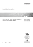
Installation and Servicing, Users and Flue Installation
Instructions
Hanging bracket
Table L.1: Items supplied with unit (TURBOmax Plus)
4
Euro B/S 086/0GB_Plus
7
DO NOT remove the boiler from the
polystrene base at this stage.
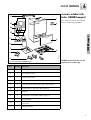
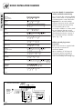
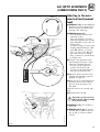
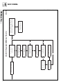
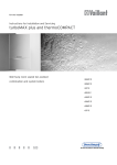
LIST OF CONTENTS
Contents included with
boiler (THERMOcompact)
11
1
Instructions for Installation
Ensure that all contents are included
before commencing installation.
BEDIENUNGSANLEITUNG
10
BEDIENUNGSANLEITUNG
2
BEDIENUNGSANLEITUNG
BEDIENUNGSANLEITUNG
10
BEDIENUNGSANLEITUNG
o
C
o
C
THERMOcompact
10
VC
VRC-
I
0
9
3
8
7
4
Euro B/S_VC_025/0
6
5
Fig. L.2: Items supplied with unit (THERMOcompact)
Item
Quantity
1
1
Boiler
2
1
Flue restriction ring
3
1
Controls cover door
4
1
Lower cover plate (packed in bottom packaging)
5
3
Flow and return service value, gas service valve
6
3
Copper tails for gas and water pipework
7
1
Template
8
2
Guarantee Card and Benchmark log book
9
1
10
3
11
1
DO NOT remove the boiler from the
polystrene base at this stage.
Description
Installation and connection accessories and
PRV packages
Installation and Servicing, Users and Flue Installation
Instructions
Hanging bracket
Table L.2: Items supplied with unit (THERMOcompact)
* for THERMOcompact 624/628 only
5
INTRODUCTION
General Information
Note: This boiler must be installed
and serviced by a competent person
in accordance with the Gas Safety
(Installation and Use) Regulations
1998. In the UK „CORGI“
registered installers undertake the
work to a safe and satisfactory
standard.
THERMOcompact boiler
The THERMOcompact is a fully
automatic, wall mounted, room sealed
system boiler for central heating and
domestic hot water (where a separate
indirect hot water storage cylinder is
also incorporated in the system).
The THERMOcompact range consists
of models with outputs of 15, 20,
24 kW and 28 kW.
All THERMOcompact boilers are
available in Natural Gas. The 20 and
28 kW versions are also available in
LPG.
TURBOmax Plus boiler
General Notes
The TURBOmax Plus is a fully
automatic, wall mounted, room sealed
combination boiler for central heating
and domestic hot water. Domestic hot
water is supplied directly from the
boiler, without requiring a copper
cylinder, cold water tank, feed and
expansion tank and associated
pipework. Domestic hot water has
priority over central heating.
The TURBOmax Plus range consists of
models with outputs for domestic hot
water of 24 kW and 28 kW. Both
versions are available in natural gas
and LPG.
The boilers have been designed for
use with a sealed central heating
system, and come fully tested and
assembled with a built in circulating
pump, expansion vessel and diverter
valve (TURBOmax Plus only). The boilers are not suitable for use on open
vented systems.
TURBOmax Plus combination boilers
incorporate a warmstart facility that
keeps the domestic hot water heat
exchanger hot, providing an
instantaneous delivery of domestic hot
water.
The temperature in the domestic hot
water heat exchanger is limited by
the boiler control system and it is not
necessary to install a scale reducer on
the cold mains to the boiler.
However, in exceptionally hard water
areas to prevent scale formation in
the property hot water system
pipework, a scale reducer may be
fitted.
The heating system can be filled using
the built-in filling loop contained
within the boiler.
6
The boilers are easily sited on any
internal wall and can be installed
with either a horizontal or vertical
RSF (room sealed fan assisted) flue.
Two types of flue systems are
available, the standard concentric flue
system (100 mm outside diameter)
and a larger diameter concentric flue
system (125 mm outside diameter)
which allows longer flue lengths to be
achieved. Flue extensions and
additional bends and elbows are
available for both flue systems to
increase the siting flexibility.
There is also a 100 mm diameter
concentric flue accessory which
connects to the alternative rear flue
outlet on the boiler for direct through
the wall installations. The boilers are
not suitable for external installation.
If desired, an inhibitor may be used
in the system. Guidance on the use of
inhibitors is contained in these
instructions.
All boilers have a built in diagnostic
system which indicates the
This feature provides key information
to aid commissioning and fault
finding.
The data badge is fitted on the rear
of the control panel.
See text of General Requirements for
installation requirements or notes.
Vaillant Ltd. support the Benchmark
initiative.
Within the information pack, you will
find a Benchmark Log Book. It is
very important that this is completed
correctly at the time of installation,
commissioning and handover to the
user.
EC designation
TURBOmax Plus (824/828) and
THERMOcompact boilers
(615/620/624/628) carry the "CE"
Mark. This demonstrates that the boilers fulfil the essential requirements of
the Gas Appliance Directive
(90/396/EEC) and the Gas
Appliance (Safety) Regulations 1992.
The "CE" Mark also demonstrates that
the boilers comply with the
requirements of the Electromagnetic
Compatibility Directive
(89/336/EEC), the Low Voltage
Directive (72/23/EEC), the Boiler
Efficiency Directive (92/42/EEC) and
the Boiler (Efficiency) Regulations
1993.
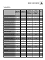
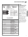
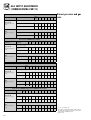
BOILER SPECIFICATION
Technical data
THERMOcompact
615/2 E
(VU GB 152/2-5)
THERMOcompact
620/2 E
(VU GB 202/2-5)
Maximum CH heat input (net
16.5 (56.100)
22.0 (74.800)
CH heat output range
(80/60 °C)
6.5 - 15
7.7 - 20
(22300 - 51200) (26300 - 68300)
THERMOcompact
THERMOcompact
624/2 E
628/2 E
(VU GB 242/2-5)
(VU GB 282/2-5)
TURBOmax Plus
TURBOmax Plus
824/2 E
828/2 E
(VUW GB 242/2-5) (VUW GB 282/2-5)
26.7 (91200)
31.1 (106200)
Units
kW (Btu/h)
8.9 - 24
10.4 - 28
kW (Btu/h)
(30400 - 81900) (35500 - 95500)
Maximum DHW heat input (net)
---
---
26.7 (91200)
31.1 (106200)
kW (Btu/h)
DHW heat output
---
---
24
28
kW
DHW flow rate ∆T = 35 °C rise
---
---
9.8
11.5
l/min
DHW flow rate at factory set
temperature rise (∆T 42 °C)
---
---
8.2
9.5
l/min
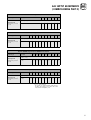
Mains water pressure required
for max. flow rate
---
---
0.5
0.5
bar
Minimum water flow rate
---
---
1.5
1.5
l/min
Mains water pressure required
for min. flow rate
---
---
0.15
0.15
bar
Maximum inlet water pressure
---
---
10
10
bar
20
20
20
20
mbar
Gas supply (G20) Gross CV (s.t.)
37.8
37.8
37.8
37.8
MJ/m3
Gas burner pressure max. rate
10.5
9.6
9.8
10.8
mbar
2.3
1.8
1.9
1.8
mbar
---
---
2.8
3.3
m3/h
35 - 82
35 - 82
35 - 82
35 - 82
°C
Minimum CH water flow
(for 20 °C rise)
650
860
1032
1203
l/h
Pump pressure available
0.25 (25)
0.25 (25)
0.25 (25)
0.25 (25)
bar (KPa)
0.75
0.75
0.75
0.75
bar
3
3
3
3
bar
Weight
38
39
41/43
43/45
kg
Primary water content
2.0
2.0
2.0
2.0
l
230/50
230/50
230/50
230/50
V~/Hz
External fuse
3
3
3
3
A
Power input
150
150
150
150
W
Case height
800
800
800
800
mm
Case width
440
440
440
440
mm
Case depth
338
338
338
338
mm
Inlet gas working pressure
required (natural gas)
Gas burner pressure ignition rate
Gas rate max. (DHW)
CH temperature flow range
Expansion vessel
pre-charge pressure
Maximum CH system pressure
Electrical supply
7
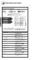
BOILER SPECIFICATION
6
8
Key:
145
148
310
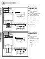
TURBOmax Plus
Boiler connections
(TURBOmax Plus)
1
Heating system return
(22 mm tail)
2
Cold water connection with shut
off valve (15 mm tail)
3
Gas connection (15 mm tail)
4
Hot water connection
(15 mm tail)
5
Heating system flow
(22 mm tail)
6
Flue outlet (100 mm flue with
turret)
7
Hanging bracket
8
Rear flue outlet
592
7
6
4 3
2
1
130
35
180
35
100
100
5
4
3
2
Euro B/S 090/2
5
1
Fig. B.1: Connection diameters TURBOmax Plus
4
6
310
THERMOcompact
Boiler connections
(THERMOcompact)
145
148
Key:
592
5
4
2
1
130
100
180
100
3
Fig. B.2: Connection diameters THERMOcompact
8
2
1
Euro B/S_VC_009/2
3
1
Heating system return
(22 mm tail)
2
Gas connection (15 mm tail)
3
Heating system flow
(22 mm tail)
4
Flue outlet (100 mm flue with
turret)
5
Hanging bracket
6
Rear flue outlet
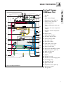
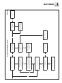
BOILER SPECIFICATION
1
31
TURBOmax Plus
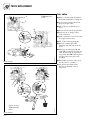
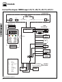
Functional Diagram
(TURBOmax Plus)
1 Air duct
2
2 Fan
30
3 Main heat exchanger
4 Temperature sensor (NTC I)
29
3
5 Flame sensing electrodes
6 Modulating burner
4
u
5
7 Fully modulating automatic gas
value
28
8 Maximum hot water temperature
control
6
9 Maximum radiator temperature
control
27
7
10 Diverter valve
26
11 DHW heat exchanger
25
8
12 Automatic bypass valve
24
23
C
13 CH flow service valve
i
9
14 Hot water outlet
C
22
21
15 Gas service valve
16 Cold water service valve
10
17 CH return service valve
11
20
18 Pressure relief valve
19
19 Aqua sensor (DHW flow switch)
20 Temperature sensor (NTC III)
12
21 Main on/off control
18
22 Pressure gauge
13
14
23 Display
17
16
24 Expansion vessel
15
25 Expansion vessel charging valve
26 Circulating pump
Fig. B.3: Functional Diagram TURBOmax Plus
Euro B/S 196/0
27 Automatic air vent
28 Ignition electrode
29 Temperature sensor (NTC II)
30 Air pressure switch
31 Flue gas duct
9
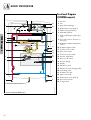
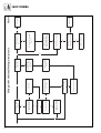
BOILER SPECIFICATION
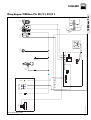
Functional Diagram
(THERMOcompact)
1
1 Air duct
25
2 Fan
2
3 Main heat exchanger
24
4 Temperature sensor (NTC I)
5 Flame sensing electrodes
3
23
6 Modulating burner
4
5
8 This control has no function on
this boiler
22
6
9 Maximum radiator temperature
control
21
7
10 Automatic bypass valve
11 CH flow service valve
20
12 Gas service valve
19
8
13 CH return service valve
18
17
14 Pressure relief valve
15 Main on/off control
9
16
15
16 Pressure gauge
17 Display
18 Expansion vessel
19 Expansion vessel charging valve
20 Circulating pump
21 Automatic air vent
10
22 Ignition electrode
14
23 Temperature sensor (NTC II)
11
24 Air pressure switch
13
25 Flue gas duct
12
Fig. B.4: Functional Diagram THERMOcompact
10
Euro B/S_VC_079/0
THERMOcompact
7 Fully modulating automatic gas
value
GENERAL REQUIREMENTS
Related Documents
The installation of the boiler must be
in accordance with the relevant
requirements of Gas Safety
(Installation and Use) Regulations
1998, Health and Safety Document
No. 635 (The Electricity at Work
Regulations 1989), BS7671
(IEE Wiring Regulations) and the
Water Supply (Water Fittings)
Regulations. It should also be in
accordance with the relevant
requirements of the Local Authority,
Building Regulations, Building
Standards (Scotland) Regulations and
the relevant recommendations of the
following British Standards:
Ensure that ALL regulations
are observed.
Euro B/S 006/0_GB
BS 5440: Flues and ventilation of
gas fired boilers not exceeding
70 kW net:
- Part 1: Flues
- Part 2: Ventilation
Fig. R.1
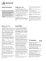
Preliminary remarks
This appliance should only be
installed in conjunction with a Vaillant
flue system.
Install the flue system as detailed in
the separate flue installation
instructions supplied with this boiler.
BS 5449: Specification for forced
circulation hot water for domestic
premises.
BS 5546: Specification for gas hot
water supplies for domestic premises.
BS 6700: Services supplying water
for domestic use within buildings and
their curtilages.
BS 6798: Specification for
installation of gas fired boilers not
exceeding 60 kW input.
BS 6891: Specification for
installation of low pressure gas
pipework up to 28 mm (R1) in
domestic premises (2nd family gas).
BS 7593: Treatment of water in
domestic hot water central heating
systems.
Institute of Gas Engineers Publication
IGE/UP/7/1998: Guide for
Installation in Timber Framed
Housing.
Important: The appliance must be
installed and serviced by a
competent person as stated in the
Gas Safety (Installation and Use)
Regulations 1998.
11
GENERAL REQUIREMENTS
Boiler location
Gas Supply
The location chosen for the boiler
must permit the provision of a
satisfactory flue termination. The
location must also provide adequate
space for servicing and air circulation
around the boiler. The boiler may be
installed in any room, although
particular attention is drawn to the
requirements of BS7671 (IEE
Regulations) and, in Scotland, the
electrical provisions of the Building
Standards (Scotland) Regulations, in
respect of the installation of a boiler
in a room containing a bath or
shower.
The gas supplier should ensure the
availability of an adequate supply of
gas.
Note: Where a room sealed boiler
is installed in a room containing a
bath or shower, any electrical switch
or boiler control utilising mains
electricity should be so situated that
it cannot be touched by a person
using the bath or shower.
Where the installation of the boiler
will be in an unusual location, special
procedures may be necessary and BS
5546 and BS 6798 give detailed
guidance on this aspect. The boiler
must be mounted on a flat, vertical
wall, which must be sufficiently robust
to take the weight of the boiler. The
boiler may be installed on a
combustible wall, subject to the
requirements of the Local Authorities
and Building Regulations.
A compartment used to enclose the
boiler must be designed and
constructed specifically for this
purpose. (An existing cupboard or
compartment may be used provided
that it is modified for the purpose).
Details of essential features of
cupboard/compartment design
including airing cupboard
installations are given in BS 6798.
If the boiler is to be fitted in a timber
framed building, it should be fitted in
accordance with Institute of Gas
Engineers Publication
IGE/UP/7/1998 „Guide for Gas
Installation in Timber Framed
Housing“.
12
A gas meter may only be connected
to the service pipe by the supplier of
gas or their contractor.
An existing meter should be checked
to ensure that it is capable of passing
the rate of gas supply required.
Installation pipes should be fitted in
accordance with BS 6891.
Pipework from the meter to the boiler
must be of an adequate size. Do not
use pipes of a smaller size than the
boiler gas connection (15 mm).
The complete installation must be
tested for soundness and purged as
described in BS 6891.
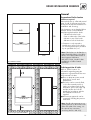
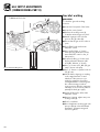
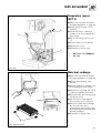
GENERAL REQUIREMENTS
Flue system
800
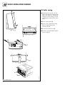
Note: The boilers are delivered
ready for installation utilising a top
outlet flue assembly. For installation
with a rear outlet flue assembly refer
to the boiler flue outlet adaptation
instructions supplied with the rear
flue accessory.
48
LAS Euro B/S 037/0
4
48
48
LAS Euro B/S 036/0
603
1285
Fig. R.2: Art.-No. 303 807
Fig. R.3: Art.-No. 303 800
Top outlet flue system
(100 mm outside diameter)
Extended top outlet flue system
(125 mm outside diameter)
The top outlet horizontal flue system
(Art. No. 303 807) is suitable for
installations up to 720 mm measured
from the centre of the boiler flue outlet
to the outside face of the wall.
Flue extensions are available to
extend this length up to 5.3 m for
15/20 kW; 4.5 m for 24 kW and
3.2 m for 28 kW.
Both 90° bends and 45° elbows are
also available to increase siting
flexibility.
A top outlet horizontal flue system of
125 mm outside diameter is also
available (Art. No. 303 609) and
can be used to achieve flue lengths of
up to 12.9 m for 15/20/24 kW;
10 m for 28 kW.
Both 45° and 90° bends and elbows
are also available to increase siting
flexibility.
A vertical flue system is also available
(Art. No. 303 800).
A vertical 125 mm concentric flue
system is also available
(Art. No. 303 600).
Refer to flue system installation
instructions for full details.
Refer to flue system installation
instructions for full details.
800
LAS Euro B/S 073/0
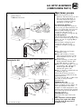
Rear outlet flue system
(100 mm outside diameter)
Fig. R.4: Art.-No. 303 817
The rear outlet horizontal flue system
(Art. No. 303 817) is suitable for
installations up to 600 mm wall
thickness.
1103
Fig. R.5: Art.-No. 303 609
GU LAZ 082/0
70
15
70
13
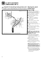
GENERAL REQUIREMENTS
Flue termination
The following details refer to both
flue systems.
a. The terminal must be positioned
such that the products of
combustion can disperse freely at
all times.
A
G
B F
G
BCD
F
J
A
A
E
F
F
M
L
K
L K
A
G
Fig. R.6: Flue termination
14
c. If the terminal is fitted less than
2 m above a balcony, above
ground or above a flat roof to
which people have access then a
suitable terminal guard;
280 mm x 280 mm x 270 mm
deep, must be provided and fitted
(made by Tower Flue Components,
Tonbridge, TN9 1TB).
GW 595/2
I
H,
b. In certain weather conditions a
plume of water vapour may be
visible from the flue terminal.
Positions where this could be a
nuisance should be avoided.
Terminal position for fan-assisted flue (minimum distance)
mm
A1)
Directly below an openable, above an opening or
horizontal to an opening i.e. air brick, opening
window or other , etc
300
B
Below gutters, soil pipes or drain pipes
25
C
Below eaves
25
D
Below balconies (below car port roof)
25
E
From vertical drain pipes and soil pipes
25
F
From internal or external corners
25
G
Above ground or balcony level
300
H
From a surface or boundary facing a terminal
600*
I
From a terminal facing a terminal
1200
J
From an opening in a car port (e.g. door, window)
into a dweling
1200
K
Vertically from a terminal on the same wall
1500
L
Horizontally from a terminal on the same wall
300
M
Distance from adjacent wall for vertical Flue
500
Note: Vertical flues must not
terminate within 600 mm of an
openable window, air vent or any
other ventilation opening.
Where a terminal is fitted less than
1 m below a plastic gutter or less
than 0.5 m below painted eaves or
any other painted surface then a suitable shield at least 1 m long should
be fitted to protect the surface.
1)
In addition, the terminal should not be nearer
than 150 mm to an opening in the building fabric
formed for the purpose of accommodating a built-in
element such as a window.
* BS 5440-1 It is recommended that a fanned flue
terminal should be positioned as follows: a) at least
2 m from an opening in a building directly opposite,
and b) so that the products of combustion are not
directly directed to discharge across a boundary.
GENERAL REQUIREMENTS
Air supply
Detailed recommendations for air
supply are given in BS 5440: Part 2.
It is not necessary to have an air vent
in the room or internal space in which
the boiler is installed.
Cupboard or compartment Electrical supply
ventilation
A 230 V, ~ 50 Hz single phase
The boilers are very high efficiency
appliances. As a consequence the
heat loss from the
appliance casing during operation is
very low. For cupboard or
compartment installations it is
therefore not necessary to provide
any high or low level permanent air
vents for cooling purposes.
electricity supply fused to 3 Amp.
must be provided in accordance with
the latest edition of BS7671 (IEE
Wiring Regulations) and any other
local regulations that may apply.
The method of connection to the
mains electricity supply must provide
a means of completely isolating the
boiler and its ancillary controls.
Isolation is preferably by the use of a
fused three pin plug and unswitched
shuttered socket outlet, both
complying with the requirements of
BS 1363. Alternatively, a 3 Amp.
fused doublepole switch with a 3 mm
contact separation on both poles may
be used.
This appliance must be earthed.
15
GENERAL REQUIREMENTS
Guide to system
requirements
Water circulation system
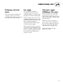
Filling and make up
Detailed recommendations for the
water circulation system are given in
BS 6798 and BS 5449: Part 1 (for
small bore and micro bore central
heating systems).
The system can be filled using the
built in filling loop (TURBOmax Plus
only) or via a separate filling point
fitted at a convinient position on the
heating circuit (THERMOcompact).
The connection must be removed
when filling is completed. Where
local Water Authority regulation does
not allow temporary connection, a
sealed system filler pump with break
tank must be used. The heating
system will not be filled automatically
from the domestic hot water side.
Pipework not forming part of the
useful heating surface should be
insulated to help prevent heat loss
and possible freezing, particularly
where pipes are run through roof
spaces and ventilated underfloor
spaces.
Draining taps must be located in
accessible positions which permit the
draining of the whole system
including the boiler and the hot water
system. Draining taps should be at
least 1/2 in. BSP nominal size and
be in accordance with BS 2879.
The boiler is suitable for use with
minibore or microbore systems.
Copper tubing to BS 2871: Part 1
should be used for water carrying
pipework. All capillary joints in all
DHW pipework must be made with
lead free solder.
Particularly where a new boiler is to
be fitted to an existing system, it is
good practice that the system is
thoroughly cleansed. This cleansing
should take place prior to the fitting
of the new boiler and be in
accordance with BS 7593.
For advice on the application of
system cleansers contact either
Sentinel, Betz Dearborn Ltd. Widnes,
Cheshire, WA8 8UD.
Tel: 0151 495 1861
or:
Fernox
Alpha-Fry Technologies
Tandem House
Marlow Way, Beddington Farm Road
Croydon CRO 4xS
Tel. 0870 601 5000
Fernox technical
help line 01799 550811
16
(Alternative methods of filling sealed
systems are given in BS 5449).
Pressure relief valve
A pressure relief valve is provided
with the boiler. This safety device is
required on all sealed C.H. systems
and is preset at 3 bar and provided
with a 15 mm compression connection for a discharge pipe, which must
be of no less than 15 mm in diameter. The Pressure Relief Valve must
not be used for draining purposes.
Pressure gauge
This is factory fitted to the boiler and
indicates the primary circuit pressure
to facilitate filling and testing.
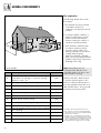
GENERAL REQUIREMENTS
Initial system pressure (bar)
Pressure relief valve setting (bar)
Vessel Volume [L]
1.0
1.5
3.0
Total water content of system
litres
25
50
100
125
150
175
200
225
250
275
300
325
350
375
400
425
450
475
500
For system volumes other than those given above,
multiply the system volume by the factor across
Table R.2: Sizing of additional expansion vessel
2.7
5.4
10.9
13.6
16.3
19.1
21.8
24.5
27.2
30.0
32.7
35.7
38.1
40.9
43.6
46.3
49.0
51.8
54.5
3.9
7.8
15.6
19.5
23.4
27.3
31.2
35.1
39.0
42.9
46.8
50.7
54.6
58.5
62.4
66.3
70.2
74.1
78.0
0.109
0.156
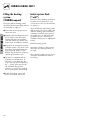
Expansion vessel
The 15 and 20 kW THERMOcompact
boilers as well as the 24 kW
TURBOmax Plus boiler incorporate a
6 litre expansion vessel which is suitable for a sealed heating system with
a maximum water content of 60 litres.
A 10 litre expansion vessel kit is
available as an optional accessory
for for the TURBOmax Plus 24 kW
boiler and the 15 and 20 kW
THERMOcompact boilers.
The 28 kW TURBOmax Plus and 24,
28 kW THERMOcompact boilers
incorporate a 10 litre expansion
vessel which is suitable for a sealed
heating system with a maximum water
content of 100 litres.
If the nominal capacity of the built in
expansion vessel is not sufficient for
the heating system (for instance in
case of modernization of old open
systems) an additional expansion
vessel can be installed external to the
boiler. It should be fitted in the return
pipe as close as possible to the boiler
in accordance with BS 5449: Part 1.
Guidance on the sizing of an
additional expansion vessel is given
in Table R.2.
17
GENERAL REQUIREMENTS
Pump specifications
Circulating pump
The circulating pump is included in
the boiler. The pump head available
for the heating system is shown in
fig. R.7.
Lift [mbar]
700
650
600
550
500
450
System by-pass
400
350
300
An automatic system by-pass is
included within the boiler. The boiler
is suitable for use in systems with
thermostatic radiator valves and no
additional by-pass is required.
Pump switch in position II (pre-delivery setting)
250
200
150
Pump switch in position I
100
0
100
200
300
400
500
600
700
800
900
1000
1100
1200
1300
Volume flow [l/min]
Fig. R.7: Pump specifications
1400
Euro B/S_VC_010/0GB
50
Venting
The boiler is fitted with an automatic
air vent. Additional provision should
be made to enable the heating system
to be vented during filling and
commissioning either by automatic air
vents or manually.
DHW expansion vessel accessory
(TURBOmax Plus only)
A DHW expansion vessel kit
(Art. No. 306 237) is available as an
optional extra from Vaillant Ltd. This
expansion vessel kit should be fitted
to the boiler whenever, either a stop
valve of the loose jumper type or a
non return valve are present in the
cold water mains supply to the boiler.
18
BOILER INSTALLATION SEQUENCE
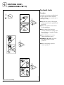
|y{
y,,
yyy
,,,
|
z
y
,
,,
z
y
,
|
{
y
,,,,,,,,,,
yyyyyyyyyy
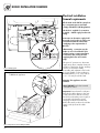
General
440
Clearances required
Mount the boiler on a flat and vertical
area of wall of sufficient area for the
boiler plus the required clearances for
installation and servicing.
yyyyyy
,,,,,,
,yy,
y,y,
y,
Preparation of boiler location
The clearances are as detailed below
and are shown on the installation
template supplied with the boiler:
-
800
* Clearance is only required to
enable easier access to the boiler
for servicing and may be provided
by an openable door, etc.
Euro B/S 089/0
338
Fig. I.1: Dimensions of boiler
Euro B/S 088/0GB
yyyyyyyyyy
,,,,,,,,,,
,
y
,,,,,,,,,,
yyyyyyyyyy
,
y
,,,,,,,,,,
yyyyyyyyyy
,,,,,,,,,,
yyyyyyyyyy
y
,
y
,
yy
,,
,,,,,,,,,,
yyyyyyyyyy
,,,,,,,,,,
yyyyyyyyyy
,,,,,,,,,,
yyyyyyyyyy
,,,,,,,,,,
yyyyyyyyyy
y
,
,,,,,,,,,,
yyyyyyyyyy
Fig. I.2: Free space required for installation
150 mm below the boiler
5 mm on either side of the boiler
210 mm on top of the boiler
500 mm in front of the boiler*
Note: If the boiler is to be fitted in a
timber framed building, it should be
fitted in accordance with Institute of
Gas Engineers Publication
IGE/UP/7/1998 „Guide for Gas
Installations in Timber Framed
Dwellings“.
Selecting position of boiler
Refer to „Boiler location“ for
information regarding siting the
appliance. In general the boiler must
be positioned such that:
● There is adequate space around
the boiler for service and
maintenance.
● The boiler can be correctly flued,
i.e. the flue terminal position is
sited in accordance with the flue
termination section (see page 14)
and the air/flue duct can be
installed in accordance with the
flue installation instructions
supplied.
● All necessary pipework can be
connected, including the pressure
relief valve.
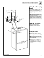
Note: Should it be necessary to run
system pipework to above the boiler
within the width of the casing, use
the optional top connection
accessory (Art.No. 306 251).
19
BOILER INSTALLATION SEQUENCE
Using boiler template
Fix the paper template to the wall
ensuring that the correct flue exit
point has been identified, ensure that
the template is vertical.
The template shows
- The position of the fixing holes for
the boiler mounting bracket (1).
- The position of the connections.
- The position of the flue exit hole.
- Upper hole (2) indicates top outlet
flue with flue turret facing
rearward.
- Lower hole (3) indicates rear outlet flue exiting directly through
wall.
Mark the position of the hanging
bracket fixing holes (1).
Drill 2 holes Ø 8 mm for the hanging
bracket.
60/100
210
2
5
5
3
1
Note: Use alternative fixing holes
where necessary.
Fig. I.3: Using Boiler template
20
TURBOmax only
124163 03
124163_03
240/242/280/282/615/620/624/628/824/828
Pro/Plus
240/242/280/282/824/828 Pro/Plus
07/2000
Identify correct flue exit.
Mark the centre of the selected air/
flue duct and its circumference, e.g.
by drilling through the template. For
installation of a rear exit outlet please
refer to the installation instructions of
the rear exit outlet kit
(Art. No. 303 817).
Other flue options
Flue instructions for other flue systems
such as vertical RSF flues, flues run to
the side of the boiler and the use of
additional bends etc. are detailed in
the flue installation instructions
provided with the boiler.
Remove the template from the wall
and plug the drilled holes using the
wallplugs supplied.
BOILER INSTALLATION SEQUENCE
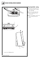
Fitting the boiler hanging
bracket
Fix the hanging bracket (2) to the wall
using the screws supplied. (it may be
necessary to use additional or
alternative fixings to ensure adequate
support).
320
131
105
131
Note: If the boiler is to be fitted in a
timber framed building ensure that
the bracket is secured to a
substantial part of the timber frame
capable of taking the weight of the
boiler.
2
105
22
27
26,5
1
Install the flue system
Install the flue system (refer to
separate air/flue duct installation
instructions).
3
Fitting the boiler
● Lift the boiler (3) up to the wall so
that it is slightly above the hanging
bracket (1).
Note: Lift the boiler from either side
at the bottom edge.
Fig. I.4: Fitting the boiler
Euro B/S 091/0
● Lower the boiler slowly onto the
hanging bracket so that the cross
member at the rear of the boiler
fully engages onto the hanging
bracket.
21
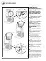
BOILER INSTALLATION SEQUENCE
Removing boiler casing
90°
90°
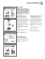
● Turn both securing fasteners (1)
anti-clockwise by 90° to release
control panel (2).
● Pull the case (3) forward at the
bottom to disengage from the
securing clips.
1
VRC-VC
I
0
● Lift the case slightly to clear the top
locations and pull forward to
remove.
2
I
0
3
picture shows TURBOmax Plus
Fig. I.5: Remove of boiler casing
22
Euro B/S 087/1
☞
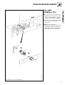
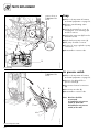
Gas supply
(TURBOmax Plus)
● Connect the 15 mm compression
gas service cock (1) and 15 mm
copper outlet tail (3) as supplied
with the appliance (2) and tighten.
● Connect a gas supply pipe of not
less than 15 mm diameter to the
copper tail.
● Tighten all connections.
(Ensure the gas supply pipework is
adequately sized such that a 20
mbar gas pressure is available at
the boiler inlet at full flow rate).
I
0
3
1
Fig. I.6: Fitting the gas connection TURBOmax Plus
Euro B/S 046/0GB
2
23
TURBOmax Plus
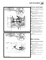
BOILER INSTALLATION SEQUENCE
BOILER INSTALLATION SEQUENCE
TURBOmax Plus
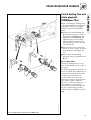
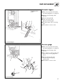
Cold water mains inlet
and hot water outlet
(TURBOmax Plus)
Flush all foreign matter from the mains
supply before connecting to the
boiler.
● Connect the cold water service
valve (1) to the cold inlet water
connection (3) of the appliance
with the washer (2) provided and
tighten.
I
0
● Connect the 15 mm cold water
inlet pipe copper tail (4) to the cold
water service valve (1) and tighten.
● Connect the 15 mm hot water
outlet copper tail (6) to the hot
water outlet connection of the
appliance (8) with the washer
provided (7) and tighten.
Note: The hot water outlet union
nut is packed in with the PRV fitting
pack.
4
● Connect the cold water service
pipe and hot water outlet pipework
to the copper tails.
6
1
2
7
3
Fig. I.7: Fitting the hot and cold water connections TURBOmax Plus
24
Euro B/S 045/0GB_Plus
8
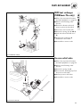
Central heating flow and
return pipework
(TURBOmax Plus)
Before connecting the heating circuit
to the boiler appliance, all pipework
and radiators must be thoroughly
flushed to remove any installation
debris.
● Connect the central heating flow
(6) and return (1) service valves to
the appliance (8 and 3) with the
washers provided (2 and 7) and
tighten the nuts. Ensure that the
valve spindles face downwards
and the drain points face to either
side of the boiler.
I
0
● Connect the 22 mm copper pipe
tails to the service valves as shown
in the illustration and tighten the
nuts.
4
● Connect the central heating
pipework to the flow (9) and return
(4) tails.
1
2
Pressure Relief Valve
Connect a discharge pipe not less
than 15 mm diameter to the outlet of
this valve.
9
The discharge pipework should be as
short as possible and installed with a
continuous fall away from the boiler.
3
6
The pipe should terminate in a
position which ensures that any
discharge of water or steam from the
valve cannot create a hazard to
persons in or about the premises, or
cause damage to any electrical
components or external wiring, and
the point of discharge should be
clearly visible (see diagram in plastic
bag).
7
Fig. I.8: Central heating flow and return pipework TURBOmax Plus
Euro B/S 044/0GB_Plus
8
25
TURBOmax Plus
BOILER INSTALLATION SEQUENCE
BOILER INSTALLATION SEQUENCE
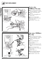
Gas supply
(THERMOcompact)
● Connect the 15 mm compression
gas service cock (1) and 15 mm
copper outlet tail (3) as supplied
with the appliance and tighten.
● Connect a gas supply pipe of not
less than 15 mm diameter to the
copper tail.
● Tighten all connections.
(Ensure the gas supply pipework is
adequately sized such that a 20
mbar gas pressure is available at
the boiler inlet at full flow rate).
I
THERMOcompact
0
3
1
Fig. I.9: Fitting the gas connection THERMOcompact
26
Euro B/S_VC_027/0
2
BOILER INSTALLATION SEQUENCE
Central heating flow and
return pipework
(THERMOcompact)
● Connect the central heating flow
(6) and return (1) service valves to
the appliance (8 and 3), with the
washers (2 and 7) provided and
tighten the nuts. Ensure that the
valve spindles face downwards
and the drain points face to either
side of the boiler.
I
0
● Connect the 22 mm copper pipe
tails to the service valves as shown
in the illustration and tighten the
nuts.
4
● Connect the central heating
pipework to the flow (9) and return
(4) tails.
1
2
Pressure Relief Valve
Connect a discharge pipe not less
than 15 mm diameter to the outlet of
this valve.
9
The discharge pipework should be as
short as possible and installed with a
continuous fall away from the boiler.
3
6
The pipe should terminate in a
position which ensures that any
discharge of water or steam from the
valve cannot create a hazard to
persons in or about the premises, or
cause damage to any electrical
components or external wiring, and
the point of discharge should be
clearly visible (see diagram in plastic
bag).
7
Fig. I.10: Central heating flow and return pipework THERMOcompact
Euro B/S_VC_017/0
8
27
THERMOcompact
Before connecting the heating circuit
to the boiler appliance, all pipework
and radiators must be thoroughly
flushed to remove any installation
debris.
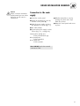
BOILER INSTALLATION SEQUENCE
Connection to a Vantage
unvented cylinder
(THERMOcompact)
● For connecting a Vaillant Vantage
unvented cylinder please refer to
the Vantage installation instructions
provided with the cylinder.
28
Connect the flue system
to the boiler
● Refer to separate air/flue duct
installation instructions included
with the boiler.
BOILER INSTALLATION SEQUENCE
29
BOILER INSTALLATION SEQUENCE
Electrical installation
General requirements
All electrical work shall be carried out
by a competent person and shall
comply with BS7671 (IEE Regulations).
3
The boiler is supplied for connection
to 230 V, ~ 50 Hz supply fused at 3 A
rating.
Connection to the mains supply shall
be made via a fused 3 pin plug to an
unswitched shuttered socket, both
complying to the requirements of
BS1363.
7 8 9
L N
3 4 5
RT 24V
230V
RT 230V
(Alternatively, connection may be
made via a 3 A fused double pole
isolator having a contact separation
of at least 3 mm in all poles and
supplying the boiler and controls
only).
Euro B/S 057/0
Do Not Use!
Fig. I.11: Wiring system
☞
picture shows
TURBOmax appliance
The point of connection to the mains
supply must allow complete electrical
isolation of the boiler and its ancillary
controls. It should be readily
accessible and adjacent to the boiler.
A 3 core flexible cord according to
BS6500 tables 6, 8 or 16 (3 x 0.75
to 3 x 1.5 mm2) should be used.
Warning: This appliance must be
earthed.
Note: DO NOT use boiler terminal
connections 7-8-9.
2
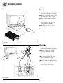
Important: Ensure that all cords pass
through the cable clamps in the rear
of the control box and are securely
fixed. Ensure that the power supply is
connected such that the current
carrying conductors become taut
before the earth conductor should the
supply cord slip from the cable
clamp.
Fig. I.12: Exposed rear view of switchgear cabinet
30
Euro B/S 047/0
1
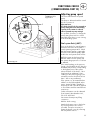
BOILER INSTALLATION SEQUENCE
Caution
Mains connection terminals L
and N remain live even when
the boiler on/off control is
switched off.
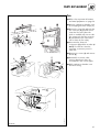
Connection to the main
supply
● Lower the control panel.
● Unclip the terminal box cover (1)
from the control panel (2).
● Refit the terminal box cover by
pushing into place until it clips
back into position.
● Feed the power supply cord in to
the appliance as shown (fig I.11).
● Raise the control panel and secure
in place.
● Use cable clamps.
● Connect the power supply cord as
follows (Fig. I.13, on page 32).
Green/yellow (earth) wire
boiler terminal Earth sign
Blue (neutral) wire
boiler terminal N
Brown (live) wire
boiler terminal L
Note: DO NOT use boiler terminal
connections 7-8-9.
31
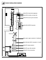
BOILER INSTALLATION SEQUENCE
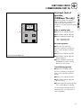
Electronic board layout
Socket X2 for internal unit components
Socket X4 for minority reversing valve
Socket X7 for accessory box connection
Socket X8 for VRC-VC connection
F3
7 8 9
24V
Do not use!
L N
Mains power supply: connections L, N and earth
3 4 5
230V
Room thermostat, 230 V: connections 3, 4 and 5
Socket X12: pump connection
Socket X14: gas valve connection
F1
Fig. I.13: Connection wiring
32
Euro B/S 125/1
Socket X13: fan unit connection
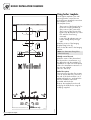
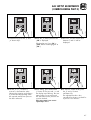
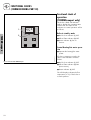
Controls
(TURBOmax Plus boiler)
Connection details for programmable thermostats
ACL Drayton
Lyfestyle PT271, PT371
L
L
N
3
ACL Drayton
Digistat 2, 3, 4
1
2
3
N
3
ACL Drayton
Digistat RF - SCR Receiver
Danfoss Randall
TP4, TP5, TP5E
1
2
3
4
External electrical controls
4
The boiler terminals 3, 4 and 5 are
for connecting external
electrical controls such as a time
switch and/or room thermostat.
4
L
N
1
L
N
3
3
2
1
N
1
4
2
3
4
Terminals 3 and 4 are linked together
when the boiler is supplied. If external
controls are used, this link must be
removed, and the controls connected
across terminals 3 and 4.
3
Danfoss Randall
TP5E RF with receiver RX1
L
L
N
Danfoss Randall
TP75
A
B
Grässlin Towerchron
RTC7
1
2
3
A
B
C
Connection of external controls
3
4
1
2
3
4
Connection details for programmable
room thermostats.
3
4
L
L1
3
4
Fig. I.14 shows the connection details
where a programmable room
thermostat (time switch with built in
room thermostat) is used to control the
boiler.
4
2
3
C
1
3
4
4
2
3
3
3
Honeywell
CM61, CM67, CM31, CM37
Horstmann
Centaurstat 1, 7
Landis & Staefa
REV 11, REV 15, REV 22
4
3
4
Smiths Timeguard
ProgramaSTAT PRT11, PRT17
L
N
L
N
3
Sunvic
TLX 6501
1
2
3
3
4
L
N
L
N
F
L
Sunvic
TLX RFP, TLX RFD
Vaillant
VRT 9083QT, VRT 9084QW
4
5
4
6
Terminal 5 is an additional neutral
connection for external neutrals such
as from the anticipator of a room
thermostat.
Important: The arrowed numbers
indicate connection into the relevant
terminal in the boiler terminal strip.
1
2
3
3
4
9
7
8
N
3
4
4
Fig. I.14
33
TURBOmax Plus
BOILER INSTALLATION SEQUENCE
BOILER INSTALLATION SEQUENCE
Connection details for external time
switches and boiler terminal strip.
Connection details for time switch
L
L
N
3
ACL Drayton
Switchmaster
SM300
L
N
1
L
N
4
ACL Drayton
Switchmaster 980
L
N
1
L
N
4
Danfoss Randall
103 Series
1
2
Danfoss Randall
Set 1E, TS975
L
N
E
L
N
E
L
N
1
L
N
3
L
N
1
2
3
4
L
N
3
4
L
N
1
2
3
4
3
1
N
3
4
Danfoss Randall
TS715
Grässlin Towerchron
QE1, QM1
Honeywell
ST610A, ST6100C
3
2
3
2
3
4
L
N
L
N
E
L
N
E
Horstmann
Centaur Plus
C11, C17
L
N
E
L
N
E
Landis & Staefa
RWB7, RWB30
L
N
L
N
Potterton Myson
EP 4002, EP 5002
N
A
1
4
2
A
B
5
E
Smiths Timeguard
SupplyMASTER
FST11, FST17
1
4
3
Sunvic
Select 107
L
N
1
L
N
3
3
2
C
3
4
3
6
L
2
N
E
2
3
3
4
5
4
3
If a room thermostat is to be
connected in addition to a time switch
the wire between the time switch
„ON“ terminal and boiler terminal 4
should be broken by the contacts of
the room thermostat (see schematic
layout, Fig. I.16).
6
4
4
Vaillant optional plug in timer
accessories
Refer to the instructions supplied with
the optional accessories for
connection details.
4
1
2
3
4
5
4
3
1
2
3
4
3
2
Upon completion of all electrical
connections refit the terminal box
cover by pushing into place. The
cover is secured by two locking clips.
4
D
L
N
L
N
4
C
6
4
L
2/L 1/N
2
6
4
3
3
B
Important: The arrowed numbers
indicate connection into the relevant
terminal in the boiler terminal strip.
3
1
Horstmann
Channel Plus
H11, H17, 425 Coronet
Fig. I.15 shows the connection details
where a time switch is used without a
room thermostat to control the boiler.
4
3
1
5
E
N
E
2
3
4
5
E
4
3
E
mains supply
4
4
Fig. I.15
DO NOT USE IN UK!
20 VDC
7 8 9 L N
MAINS
SUPPLY
230 V
50 Hz
N
L
3 A FUSE
34 5
SWITCH
CONTACTS
L
N CLOCK
Fig. I.16
34
ROOM
THERMOSTAT
N
GU_Ecomax_20/0GB
TURBOmax Plus
ACL Drayton
Tempus 1, Tempus 2
Lyfestyle LP111, LP711
BOILER INSTALLATION SEQUENCE
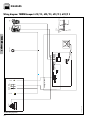
Controls
(THERMOcompact boiler)
Connection details for control systems utilising 3 port motorised valve
via external wiring centre/junction box
Diagram only applies to the specific controls mentioned
THERMOcompact
terminal strip
Programmer
for programmer connections see fig. 16.b
L
N
L
N
3
4
5
E
N
L
CENTRAL
HEATING
ON
L
N
L
N
3
4
5
E
5
3
6
HOT
WATER
ON
HOT
WATER
OFF
7
8
The boiler terminals 3, 4 and 5 are
for connecting external
electrical controls such as a
programmer, room thermostat, etc.
External wiring centre/junction box*
N
N
L
3
L
4
5
6
7
8
9
*Do not use pre-wired printed circuit board type
8
Cylinder thermostat
4
7
E
10
not used
Room thermostat
5
9
Vaillant VRT 9090
E
C
A
3
1
3
L
3
2
4
2
1
Danfoss Randall RET 230
N
3
L
Tower SS
4
2
2
3
1
1
E
4
2
1
E
2
1
E
1
3
E
ACL Drayton HTS3
2
1
C
Danfoss Randall ATC
3
2
1
Tower CS1
YL
BK RED
ACL Drayton RTS 1, 2
Honeywell L641
2
1
C
Danfoss Randall RX-1
Horstmann HTC1
3
2
1
Danfoss Randall RMT 230
Siemens-Landis & Staefa RAM 1
3
2
1
Sunvic SA 2452
2
1
3
ACL Drayton Digistat 2, 3, 4
E
E
N
Honeywell T6360
Horstmann HRT 1
Siemens-Landys & Staefa RAD 1
Sunvic TLX 2000 series
E
5
EARTH
BLUE
9
BROWN
OR
WHITE
8
4
6
L
N
C
B
ORANGE
3 Port mid position motorised valve
Fig. I.17
Lifestyle LP241, LP 522, LP 722
Tempus 6, Tempus 7
Danfoss Randall CP 715, FP715
Note:
*Earth not required
L
1
5
3
8 not used 7
6
E
N
L
1
2
3
4
5
3
8 not used 7
6
N
L
1
2
3
4
6
2
3
4
8
6
N
E
2
3
4
*
5
3
8 not used 7
Danfoss Randall Set 2E, Set 3E
Note:
*Earth not required,
Link L - 2 - 5
E
N
L
1
*
5
3
7
Grässlin Towerchron QE2
N
L
Honeywell ST699B, ST799A
Note:
Link L - 5 - 8
1
8
2
5
3
L
N
3
4
6
not used
3
5
Honeywell ST6200, ST6300, ST6400
N
L
5
3
Horstmann Channel Plus H21, H27
Note:
*Earth not required,
Link L - 2 - 5
E
N
L
1
*
5
3
7
Siemens-Landis & Staefa RWB2, RWB9
N
L
Potterton Myson EP 2002, EP 3002, EP 6002
Note:
2
5
3
7
7
8
6
3
4
8
6
8
2
3
6
not used
8
5
6
not used
6
3
N
L
1
3
4
5
3
8 not used 7
6
2
5
4
5
2
Connection details using an external
wiring centre
4
2
not used 7
Connection of external electrical
controls
6
6
8 not used 7
1
Terminal 5 is an additional neutral
connection for external controls.
4
E
Link L - 5
Sunvic Select 207
1
3
not used 7
E
Terminals 3 and 4 are linked together
when the boiler is supplied. If external
controls are used, this link must be
removed, and the controls connected
across terminals 3 and 4.
The boiler should be connected to the
system controls using an external
wiring centre. Fig. 17, 18 shows
connection details for a system
utilising a 3 port mid position
motorised valve, figure 19, 20 shows
the connection details for a system
utilising two 2 port motorised valves
connected via an external wiring centre (Important: the arrowed numbers
indicate connection into the relevant
terminal of thre external wiring
centre).
4
GREY
External electrical controls
N
L
1
3
4
5
3
8 not used 7
6
5
Fig. I.18
35
THERMOcompact
3 amp fused
main supply
BOILER INSTALLATION SEQUENCE
Connection details for control systems utilising 2 x 2 port motorised valves
via external wiring centre/junction box
Diagram only applies to the specific controls mentioned
3 amp fused
main supply
L
N
L
N
THERMOcompact
terminal strip
E
Programmer
for programmer connections see fig. 16.d
L
N
3
4
5
N
L
CENTRAL
HEATING
ON
L
N
3
4
5
5
3
6
HOT
WATER
ON
HOT
WATER
OFF
7
8
External wiring centre/junction box*
N
N
L
3
L
4
5
6
7
*Do not use pre-wired printed circuit board type
10 7
Cylinder thermostat
ACL Drayton HTS3
2
THERMOcompact
Danfoss Randall ATC
1
C
1
E
8
9
10
not used
Room thermostat
5
9
6
Vaillant VRT 9090
E
C
A
3
1
3
L
3
2
ACL Drayton Digistat 2, 3, 4
E
L
N
C
B
E
3
2
Tower CS1
YL
BK RED
ACL Drayton RTS 1, 2
Honeywell L641
2
1
C
Danfoss Randall RX-1
Horstmann HTC1
3
2
1
Danfoss Randall RMT 230
4
2
1
Siemens-Landis & Staefa RAM 1
3
2
1
Danfoss Randall RET 230
N
3
L
Sunvic SA 2452
2
1
3
Tower SS
4
2
2
3
1
1
E
4
2
1
E
2
1
E
1
3
E
E
N
Honeywell T6360
Horstmann HRT 1
Siemens-Landys & Staefa RAD 1
Sunvic TLX 2000 series
E
5
EARTH
BLUE
10
BROWN
3
GREY
4
ORANGE
4
E
5
9
3
EARTH
BLUE
BROWN
GREY
Hot water 2 port motorised valve
4
ORANGE
Central heating 2 port motorised valve
Fig. I.19
Lifestyle LP241, LP 522, LP 722
Tempus 6, Tempus 7
Danfoss Randall CP 715, FP715
Note:
*Earth not required
2
1
3
N
L
5
not used
7
3 not used
E
N
L
5
3 not used
N
L
E
4
6
2
3
4
not used
7
6
2
3
4
6
1
1
*
5
3 not usednot used 7
Danfoss Randall Set 2E, Set 3E
Note:
*Earth not required,
Link L - 2 - 5
E
N
L
1
*
5
3
7
Grässlin Towerchron QE2
N
L
5
3 not usednot used 7
L
N
3
3
5
6
N
L
6
2
3
Honeywell ST699B, ST799A
Note:
Link L - 5 - 8
Honeywell ST6200, ST6300, ST6400
2
4
3
5
2
3
5
3 not usednot used 7
Horstmann Channel Plus H21, H27
Note:
*Earth not required,
Link L - 2 - 5
E
N
L
1
*
5
3
7
Siemens-Landis & Staefa RWB2, RWB9
N
L
5
3 not used
E
N
L
5
Potterton Myson EP 2002, EP 3002, EP 6002
Note:
Link L - 5
Sunvic Select 207
Fig. I.20
36
1
3
not used
7
4
6
4
3 not usednot used 7
6
5
3 not used
5
2
not used
3
4
7
6
6
not used
4
3
1
8
4
7
L
not used
6
6
2
N
6
4
not used 6
2
1
5
7 not used
not used
1
4
not used 6
2
1
3
5
BOILER INSTALLATION SEQUENCE
Thermostatic radiator valves
Anti-cycling ‘economiser’ control
The boiler has a built in automatic
bypass valve making it ideal for use
in systems with thermostatic radiator
valves (no separate system bypass is
required).
The boiler incorporates a built in
anti-cycling control to ensure that
energy wasteful short cycling of the
boiler cannot occur. This control
prevents the boiler from re-igniting for
a preset period of 5 minutes after
central heating operation (the hot
water operation is unaffected by this
control and hot water can be drawn
at any time).
For optimum fuel economy it is
recommended that where TRV’s are
used they are used in conjunction
with a programmable room
thermostat or separate timer and
room thermostat to ensure complete
boiler shut down when the heating
demand is satisfied. (The radiator in
the room containing the room
thermostat should not be fitted with a
TRV).
Note: To temporarily override the
anti-cycling control turn the main
boiler on/off switch to the off
position „0“ and then back to the on
position „I“ after a few seconds.
Automatic pump spin control
(APS)
The boiler incorporates a built in
control which will spin the built in
circulating pump and operate the
diverter valve (TURBOmax only) once
in a 24 hour period. This control
helps to prevent seizure when the
boiler is not operated for a period of
time. This control is not active when
the power supply to the appliance is
turned off.
Frost protection
The boiler has an integral frost
thermostat which is designed for
protection of the boiler.
To protect remote or exposed parts of
the heating system or property
additional frost protection measures
must be taken such as the installation
of an external frost thermostat. This
frost thermostat should be connected
across the boiler terminals 3 and 4,
in parallel with any external heating
controls.
Circulating pump
The boiler incorporates a built in
circulating pump that is fully prewired
(no additional wiring is necessary).
The pump incorporates an automatic
overrun period after the boiler
switches off.
37
BOILER INSTALLATION SEQUENCE
Fit boiler casing
● Carefully push case (1) onto the
boiler such that the locating points
either side at the top of the boiler
engage. Push the casing onto the
securing clips at the bottom of the
boiler.
● Close control panel (2).
● Secure control panel by turning
both securing fasteners (3)
clockwise by 90°.
● Fit and close front door (4).
1
● Fit lower cover plate (5) using the
screws supplied.
I
0
2
90°
90°
3
I
0
4
Fig. I.21: Fit boiler casing
38
Euro B/S 098/1
5
COMMISSIONING PART I
Preliminary electrical
checks
Check the electrical installation by
carrying out short circuit, earth
continuity and resistance to earth tests
and a check for correct polarity.
Gas supply
The complete gas installation
including the gas meter must be
inspected, tested for soundness and
purged in accordance with BS 6891.
The gas supply to the boiler can be
purged by slackening the gas service
valve beneath the boiler. Ensure that
there is adequate ventilation,
extinguish all naked flames and do
not smoke whilst purging.
After purging, the gas service valve
connection must be retightened and
tested for soundness. (The boiler itself
does not require purging as this will
be done by the automatic burner
sequence control).
Cold water supply
(TURBOmax Plus only)
Open all domestic hot water taps
supplied by the boiler, turn on the
mains water supply to the boiler and
open the mains water isolating valve
below the boiler.
Water will now flow through the
boiler to the hot taps. Starting with
the lowest tap supplied, turn the hot
taps off one at a time until the hot
water pipework is purged of air.
Check all hot and cold water
pipework for leaks.
39
COMMISSIONING PART I
TURBOmax Plus
1
2
Fig. Com. 1: Filling TURBOmax Plus boiler
40
Eor B/S 054/0
90°
COMMISSIONING PART I
Proceed as follows to fill the system:
● Open all radiator valves on the
system.
● Check flexible filling loop is
connected.
● Locate the filling valve handle (1)
on the valve as shown.
● Open the valve slowly and fill the
unit with water until the required
amount has been added (2).
● Bleed the air from the radiators.
● The boiler is equipped with an
automatic air release valve. To
allow this to vent the boiler, the
cap top must be slackened by
1 - 2 turns. (This cap must be left
slackened during operation to
ensure any residual air or system
gases are released)
Initial system flush
(“cold“)
TURBOmax Plus
Filling the heating
system
(TURBOmax Plus)
The whole of the heating system must
be flushed out at least twice: once
cold, and once hot as instructed later
on page 53.
Open all radiator and heating valves
and the boiler CH service valves and
drain the heating system and boiler
completely from the lowest points of
the system via 1/2” BSP drain taps
(opened full bore to remove any
installation debris prior to lighting the
boiler).
Refill the heating system.
Check the operation of the pressure
relief valve by rotating the knob on
the valve.
Now check the water pressure in the
unit again (and add more water if
necessary).
Close the filling valve (1) and
disconnect the temporary connection.
41
COMMISSIONING PART I
Filling the heating
system
(THERMOcompact)
The boiler and the heating system
should be filled using a filling method
as described on page 16.
● Ensure that the boiler CH service
valves are open.
THERMOcompact
● Partially open the filling valve and
allow water to enter the system.
Starting with the lowest radiator,
open the radiator air release until
water (clear of bubbles) is emitted.
● Repeat this at all radiators until the
complete system is full, all air locks
have been cleared and the boiler
pressure gauge reads 1.5 bar.
Release any air from the pump by
slackening the centre screw.
● The boiler is equipped with an
automatic air release valve. To
allow this to vent the boiler, the
cap on the top must be slackened
by 1 - 2 turns. (This cap must be
left slackened during boiler
operation to ensure any residual
air or system gases are released).
● Check the heating system and
boiler connections are sound.
42
Initial system flush
(“cold“)
The whole of the heating system must
be flushed out at least twice: once
cold, and once hot as instructed later
on page 53.
Open all radiator and heating valves
and the boiler CH service valves and
drain the heating system and boiler
completely from the lowest points of
the system via 1/2” BSP drain taps
(opened full bore to remove any
installation debris prior to lighting the
boiler).
Refill the heating system.
Check the operation of the pressure
relief valve by rotating the knob on
the valve.
Now check the water pressure in the
unit again (and add more water if
necessary).
THERMOcompact
COMMISSIONING PART I
43
GAS SUPPLY ADJUSTMENTS
(COMMISSIONING PART II)
☞
picture shows a
TURBOmax Plus boiler
Gas inlet working
pressure
1
To check the gas inlet working
pressure:
● Lower the front panel of the boiler.
● Lower the control panel.
● Slacken the sealing screw (1)
located at measuring point „P.IN”.
● Attach U-gauge to the inlet test
point on the gas valve (2).
● Ensure that the gas service valve is
open.
● Turn off the boiler at the main
ON/OFF control.
2
Fig. G.1: Gas inlet working pressure
Anschlussdruck Turbo
● Press and hold the „+” button,
while pressing the button turn the
main ON/OFF control to the „1”
ON position.
● Continue holding „+” button until
display alternates between „P1”
and „P2”. Release „+” button.
● Press „+” button until „P1” (full gas
rate) is shown in display.
● Press „i” button to operate boiler at
full gas rate.
● Check that the U-gauge is reading
in the range between 18 and
20 mbar. If the pressure is not
within this range this should be
investigated before continuing with
the commissioning procedure.
Lower pressures than this range are
indicative of an incorrectly sized or
partially blocked gas supply.
● Switch off the boiler at the main
ON/OFF control.
● Remove U-gauge, tighten test point
sealing screw (1).
● Test for soundness.
● Record appliance working gas inlet
pressure (mbar) in the Benchmark
Installation, Commissioning and
Service Log Book.
44
GAS SUPPLY ADJUSTMENTS
(COMMISSIONING PART II)
U-Gauge connection points for Natural gas
Main burner pressure
☞
● The burner pressure on this
appliance has been factory set and
does not require adjustment. To
check the main burner pressure
connect the U-Gauge as follows
depending on the gas type.
picture shows a
TURBOmax Plus boiler
1
For natural gas appliances:
Slacken the sealing screw (1) at test
point on the gas valve and attach one
arm of a U-gauge (2) to the test point.
Remove plastic sealing plug and
connect the other arm to the
combustion chamber sensing tube (3).
For LPG appliances:
Slacken the sealing screw (1a) at test
point on the burner inlet gas pipe and
attach one arm of a U-gauge (2a) to
the test point.
Remove plastic sealing plug and
connect the other arm to the
combustion chamber sensing tube
(3a).
3
2
Connection for LPG
☞
picture shows a TURBOmax Plus boiler
1a
3a
Fig. G.2: Connection of U-gauge
Turbo H und PB
2a
● Turn off the boiler at the main
ON/OFF control.
● Press and hold the „+” button,
while pressing the button turn the
main ON/OFF control to the „1”
ON position.
● Continue holding „+” button until
display alternates between „P1”
and „P2”. Release „+” button.
● Press „+” button until „P1” is shown
in the display. „P1” indicates the
maximum gas rate and „P2”
indicates the ignition rate.
● Press „i” button to operate boiler at
maximum gas rate.
Check that the burner pressure is
correct as shown in table G3 for the
appropriate boiler.
To cancel selected „P1” or „P2” mode
press the „i” and „+” buttons
simultaneously.
TURBOmax Plus only
Measure the domestic hot water
burner operating pressure (mbar), the
heat input (kW), the inlet/outlet
domestic hot water temperatures (°C)
and flow rate (l/min) by fully opening
a hot water tap and record details in
the boiler logbook.
THERMOcompact only
Record the heat input in the boiler
logbook.
After completion of all tests tighten
sealing screw, replace the sealing
plug and check all test points for
soundness (1/1a).
45
GAS SUPPLY ADJUSTMENTS
(COMMISSIONING PART II)
This illustration shows the U-tube pressure gauge connected to a system
configured to run on natural gas. When connecting the U-tube pressure
gauge to a system running on LPG, please refer to Fig. G.2 on page 45.
☞
picture shows a
TURBOmax Plus boiler
Adjusting the central
heating output
(range rating)
The boilers are fully modulating for
central heating, and it is therefore not
necessary to range rate the boiler.
However, if desired, it is possible to
range rate the boiler, as follows:
● Connect the U-gauge to check
burner pressure.
1
● Use Table G.3 on page 48 to
determine the central heating
output required.
2
● Note the burner pressure setting.
● Turn on the central heating.
● Ensure that any thermostatic
radiator valves are open and set to
high.
● Similtaneously press and release
the „+” and „-” buttons to activate
burner pressure mode.
Fig. G.3: Using nozzle pressure to check and adjust the heating system partial load
Euro B/S 277/0
● The boiler will light at the factory
set nominal gas rate.
DO NOT open any hot water tap
while carrying out this procedure
(TURBOmax Plus only).
● Check that the U-gauge reading
corresponds to the maximum
burner pressure as detailed on the
table on page 48.
● Identify required range rating
setting and note main burner
pressure in mbar for that output.
● Adjust central heating output range
as shown on page 47.
Note: Following adjustment of the
central heating output, the new
output can be checked using the gas
rate table as detailed on page 49.
● Record central heating operating
pressure in the Benchmark Log Book
along with the heat input (kW) and
temperature difference between
flow and return.
46
Euro B/S 066/0
Euro B/S 065/0
1 Simultaneously press the „i” and
2 Keep the „+” button pressed until
„+” buttons keys.
Euro B/S 067/0
GAS SUPPLY ADJUSTMENTS
(COMMISSIONING PART II)
3 Press the „i” button and a value
„d.0” is displayed.
between 1 and 15 will be
displayed.
(The display runs from „d.0” to
„d.99” before restarting again at
„d.0”.)
4 Use the „+” or „-” buttons to
increase or decrease the value.
Observe the U-gauge as the button
is pushed and stop pushing when
the required main burner pressure
has been achieved.
5 After setting, press and hold the
„i” button for five seconds - or until
the display stops flashing. The new
setting value is now memorised.
The new main burner pressure can
now be checked.
If the new output is not correct
repeat steps 3 to 5.
Euro B/S 065/0
Euro B/S 068/0
Euro B/S 069/0
~5s
6 To return to normal mode, press
the „i” and „+” buttons
simultaneously.
The adjustment mode is also
cancelled if no button is pushed for
a period of four minutes.
47
GAS SUPPLY ADJUSTMENTS
(COMMISSIONING PART II)
Adjusting the ignition
rate
1
● Undo screw and remove the cap
(1).
● TURBOmax only: Disconnect the
modulating coil wires (2) from the
gas valve, set the DHW temperature control to maximum and fire the
boiler at full rate by fully opening a
hot water tap.
● THERMOcompact only:
- Turn off the boiler at the main
ON/OFF control.
- Press and hold the „+” button,
while pressing the button turn the
main ON/OFF control to the „1”
ON position.
- Continue holding „+” button until
display alternates between „P1”
and „P2”. Release „+” button.
- Press „+” button until „P2” (ignition rate) is shown in display.
- Press „i” button to operate boiler
at full gas rate.
2
● Using a 9 mm spanner turn the
outer hexagonal nut (3) to adjust
the ignition rate.
- Turn the nut (3) clockwise to
increase the ignation rate
- Turn the nut (3) anticlockwise to
decrease the ignation rate
● Adjust the burner pressure until it
matsches the ignition rate as detailed on page 22.
● TURBOmax only: Turn off the hot
water tap and reconnect the wires
to the modulating regulator.
3
9
● THERMOcompact only: To cancel
selected „P1“ or „P2“ mode press
the „i“ and „+“ buttons sumultaneously.
Fig. G.4
48
Euro B/S GU_GB_012/0
99
GAS SUPPLY ADJUSTMENTS
(COMMISSIONING PART II)
Adjusting to the maximum heat load (nominal
load)
● TURBOmax only: Set the DHW temperature control to maximum and
fire the boiler at full rate by fully
opening a hot water tap.
● THERMOcompact only:
- Turn off the boiler at the main
ON/OFF control.
- Press and hold the „+” button,
while pressing the button turn the
main ON/OFF control to the „1”
ON position.
- Continue holding „+” button until
display alternates between „P1”
and „P2”. Release „+” button.
- Press „+” button until „P1” (full
gas rate) is shown in display.
- Press „i” button to operate boiler
at full gas rate.
1
7
● Using a 7 mm spanner turn the
inner hexagonal nut (1) to adjust
the burner operating pressure.
- Turn the nut (1) clockwise to
increase the nominal load
- Turn the nut (1) anticlockwise to
decrease the nominal load
7
● Adjust the burner pressure until it
matsches the maximum output as
detailed on page 22.
● Now turn the 7 mm hexagonal nut
(1) anticlockwise until the burner
pressure drops by approx. 0.3 0.4 mbar.
Nominal load is now correctly adjusted.
● Refit the plastic cap (2).
2
The plastic cap (2) must be fitted for the gas valve assembly
to function correctly.
Fig. G.5
Euro B/S GU_GB_013/0
● TURBOmax only: Turn off the hot
water tap.
● THERMOcompact only: To cancel
selected „P1“ or „P2“ mode press
the „i“ and „+“ buttons sumultaneously.
49
GAS SUPPLY ADJUSTMENTS
(COMMISSIONING PART II)
Burner Pressure THERMOcompact 615/2 E
Delivered gas
Ignition
6.5
rate
Output [kW]
8.0
10.0
12.0
14.0
15.0
Burner pressure and gas
rate
Burner pressure1) [mbar]
Natural gas 2H
Main burner jet mark2)
7/120
for G20
2.3
2.3
3.3
5.0
7.0
9.3
10.5
for G30
5.8
5.8
8.1
11.9
16.3
21.5
24.3
for G31
7.5
7.5
10.5
15.4
21.2
27.9
31.6
Burner pressure1) [mbar]
LPG 3+
Main burner jet mark2)
7/072
Burner Pressure THERMOcompact 620/2 E
Delivered gas
Ignition
rate
7.7
8.0
10.0
12.0
14.0
16.0
18.0
20.0
1.8
1.8
1.9
2.8
3.8
5.1
6.4
7.9
9.6
for G30
4.1
4.1
4.3
6.2
8.5
11.3
14.3
17.7
21.4
for G31
5.4
5.4
5.6
8.1
11.1
14.7
18.6
22.9
27.6
Output [kW]
Burner pressure1) [mbar]
Natural gas 2H
Main burner jet mark2)
7/120
for G20
Burner pressure1) [mbar]
LPG 3+
Main burner jet mark2)
7/072
Burner Pressure THERMOcompact 624/2 E, TURBOmax Plus 824/2 E
Delivered gas
Ignition
rate
Output [kW]
8.9
10.0
12.0
14.0
16.0
18.0
20.0
22.0
24.0
1.9
2.1
2.9
3.7
4.7
5.8
6.7
8.4
9.8
Burner pressure1) [mbar]
Natural gas 2H
Main burner jet mark2)
7/120
for G20
1.9
Burner pressure1) [mbar]
LPG 3+
Main burner jet mark2)
7/072
for G30
4.1
4.1
4.7
6.4
8.4
10.8
13.4
16.5
20.3
24.0
for G31
5.4
5.4
6.1
8.3
10.9
14.0
17.4
21.4
26.4
31.7
Burner Pressure THERMOcompact 628/2 E, TURBOmax Plus 828/2 E
Delivered gas
Output [kW]
Ignition
10.4
rate
12.0
14.0
16.0
18.0
20.0
22.0
24.0
26.0
28.0
1.8
2.2
2.9
3.7
4.7
5.6
6.8
8.0
9.4
10.8
Burner pressure1) [mbar]
Natural gas 2H
Main burner jet mark2)
7/120
for G20
1.8
Burner pressure1) [mbar]
LPG 3+
Main burner jet mark2)
7/072
Table G.3: Burner pressure
50
for G30
4.2
4.2
5.1
6.6
8.2
10.4
12.8
17.4
18.2
21.3
24.6
for G31
5.5
5.5
6.7
8.7
11.1
13.7
16.8
22.8
23.8
27.8
32.0
1)
15 °C, 1013 mbar, dry
The nozzles are stamped with the mark shown in
this table. The marking corresponds to the nozzle
hole diameter multiplied by 100.
3)
Ignition rate
2)
GAS SUPPLY ADJUSTMENTS
(COMMISSIONING PART II)
Gas Rate THERMOcompact 615/2 E
Delivered gas
Output [kW]
6.5
8.0
10.0
12.0
14.0
15.0
0.8
1.0
1.3
1.4
1.7
1.7
Gas Rate1) [m3/h]
Natural gas 2H
Main burner jet mark2)
7/120
for G20
Gas Rate THERMOcompact 620/2 E
Delivered gas
Output [kW]
7.7
8.0
10.0
12.0
14.0
16.0
18.0
20.0
0.9
1.0
1.2
1.4
1.7
1.9
2.1
2.3
Gas Rate1) [m3/h]
Natural gas 2H
Main burner jet mark2)
7/120
per G20
Gas Rate THERMOcompact 624/2 E, TURBOmax Plus 824/2 E
Delivered gas
Output [kW]
8.9
10.0
12.0
14.0
16.0
18.0
20.0
22.0
24.0
1.1
1.2
1.4
1.7
1.9
2.1
2.4
2.6
2.8
Gas Rate1) [m3/h]
Natural gas 2H
Main burner jet mark2)
7/120
for G20
Gas Rate THERMOcompact 628/2 E, TURBOmax Plus 828/2 E
Delivered gas
Output [kW]
10.4
12.0
14.0
16.0
18.0
20.0
22.0
24.0
26.0
28.0
1.3
1.5
1.7
1.9
2.1
2.4
2.6
2.8
3.1
3.3
Gas Rate1) [m3/h]
Natural gas 2H
Main burner jet mark2)
7/120
Table G.4: Gas flow rate
per G20
1)
2)
15 °C, 1013 mbar, dry
The nozzles are stamped with the mark shown in
this table. The marking corresponds to the nozzle
hole diameter multiplied by 100.
51
FUNCTIONAL CHECKS
(COMMISSIONING PART III)
Functional checks
Procedure
I
Once the unit has been installed and
the gas supply has been checked,
operate the system to ensure that it is
working correctly.
0
● Operate the system, following the
operating instructions supplied with
the boiler.
● Check the system for water leaks
and escaping gas.
● Check that the flue has been
correctly installed, according to the
fitting instructions supplied with the
flue assembly.
● Check the burner for correct
ignition and flame picture.
● TURBOmax Plus only: Check the
hot water system for correct
operation.
● Check the heating system for
Fig. F.1: Test for correct functioning
52
Euro B/S 058/0
correct operation.
Functional check of
operation
(TURBOmax Plus only)
This boiler is fitted with indicator
lights to display the operating status
of the boiler. The status of the
indicators in normal operation will be
as follows.
1
Boiler in stand by mode
3
● Red lock out indicator (1) OFF.
2
● Yellow flame indicator (2) OFF.
● Green warmstart indicator (3).
- ON – Warmstart ON
- OFF – Warmstart OFF
Hot water operation
Fig. F.2: Functional check TURBOmax Plus
Euro B/S 071/0
● Fully open hot water tap.
If boiler is operating correctly, the
status of the indicators will be as
follows:
● Red lock out indicator (1) OFF.
● Yellow flame indicator (2) ON
(Flame indicator).
● Green warmstart indicator (3)
FLASHING (hot water is being
drawn from the system).
Central Heating operation
● Operate the heating system.
If boiler is operating correctly, the
status of the indicators will be as
follows:
● Red lock out indicator (1) OFF.
● Yellow flame indicator (2) ON
(burner active).
● Green warmstart indicator (3) ON,
OFF or FLASHING (see above).
The LCD display indicates the flow
temperature (in °C) of the boiler in
normal operation.
53
TURBOmax Plus
FUNCTIONAL CHECKS
(COMMISSIONING PART III)
FUNCTIONAL CHECKS
(COMMISSIONING PART III)
Functional check of
operation
(THERMOcompact only)
This boiler is fitted with indicator
lights to display the operating status
of the boiler. The status of the
indicators in normal operation will be
as follows.
1
Boiler in stand by mode
3
● Red lock out indicator (1) OFF.
THERMOcompact
2
● Yellow flame indicator (2) OFF.
● Green indicator (3) has no
function.
Central Heating/hot water operation
● Operate the heating/hot water
Fig. F.3: Functional check THERMOcompact
Euro B/S 071/0
system.
If boiler is operating correctly, the
status of the indicators will be as
follows:
● Red lock out indicator (1) OFF.
● Yellow flame indicator (2) ON
(burner active).
● Green indicator (3) OFF.
The LCD display indicates the flow
temperature (in °C) of the boiler in
normal operation.
54
FUNCTIONAL CHECKS
(COMMISSIONING PART III)
☞
Adjusting pump speed
picture shows a
TURBOmax Plus
application
The unit is fitted with a two-speed
pump.
The pump is delivered with the switch
(1) set to position II.
1
Important note:
The boiler should only be operated at
pump setting II because the heating
capacity for hot water is reduced
when operated at pump setting I!
It is possible, however, to change the
pump setting from Level II to Level I
manually when there is noise coming
from the heating system.
Final system flush („HOT“)
Fig. F.4: Pump speed
Euro B/S 049/0
Turn on the boiler for central heating
and allow the boiler and system to
reach operating temperature. Check
that the heating system is watertight.
Turn the boiler off and rapidly drain
both boiler and system while still hot:
Refill the system and release all air.
Release water from the system until
the system design pressure of 1.0 bar
is attained.
(The actual reading on the pressure
gauge should ideally be 0.5 bar plus
an additional pressure corresponding
to the highest point of the system
above the base of the boiler - 10 m
head equals an additional 1 bar
reading on the pressure gauge. The
minimum pressure should not be less
than 1 bar in any installation.)
If the system is to be treated with an
inhibitor it should be applied at this
stage. Sentinel X100 is suitable for
this purpose and it should be applied
in accordance with the manufacturers
instructions.
Further information can be obtained
from Sentinel, Betz Dearborn Ltd.,
Tel: 0151 4951861.
Disconnect the temporary filling
connection.
Refit the boiler casing.
Attach the bottom cover to the boiler
by securing with the four screws
provided. It may be necessary to
apapt the bottom cover by removing
the easy break sections.
55
FUNCTIONAL CHECKS
(COMMISSIONING PART III)
Handing over to the user
Set the maximum radiator temperature
control to the desired setting.
Set the maximum hot water
temperature control to the desired
setting.
Instruct the user in the safe and
efficient operation of the boiler, in
particular the function of
● The boiler on/off control
● The maximum radiator temperature
control
● The maximum hot water
temperature control (TURBOmax
Plus only)
● The pressure gauge
Show the user how to operate any
external controls.
Explain to the user the importance of
having the boiler regularly serviced
by a competent servicing company.
To ensure regular servicing, it is
strongly recommended that
arrangements are made for a
Maintenance Agreement. Please
contact Vaillant Service Solutions
(0870 6060 777) for further details.
Ensure the boiler log book is fully
completed and leave with the end
user. Failure to install and commission
this appliance to the manufacturers
instructions may invaludate the
warranty (Note: This does not affect
your statutory rights).
Leave the user instructions and the
boiler log book in the clips provided
in the front panel of the boiler.
Leave the installation and servicing
instructions with the user.
Note: Fit the Benchmark Log Book
under the users instructions.
56
SERVICING
Initial Inspection
To ensure the continued safe and
efficient operation of the boiler it is
recommended that it is checked and
serviced as necessary at regular
intervals. The frequency of servicing
will depend upon the particular
installation conditions and usage, but
in general once per year should be
adequate. It is the law that all servicing work is carried out by a competent person (Corgi registered).
Important: Before starting any
maintenance work:
● Isolate the mains electricity supply
by disconnecting the plug at the
socket outlet (if there is only an
isolating switch remove the fuse
from the switch).
Before commencing any servicing or
maintenance work, carry out an initial
inspection of the system as follows:
● Inspect the flue, pipework and
electrical connections for
indications of damage or
deterioration.
● Inspect the air supply and
ventilation arrangements of the
installation.
● Check the heating and water
system, in particular the condition
of radiator valves, evidence of
leakage from the heating system
and dripping hot water taps.
Functional check of boiler operation
● Carry out a functional check of the
service valve fitted to the boiler.
boiler operation as prevoiusly
detailed.
● Always test for gas soundness and
● Remove the appliance casing as
● Turn OFF the gas supply at the gas
always carry out functional checks
after any service work and after
exchanging any gas carrying
component.
● Always check earth continuity,
polarity and resistance to earth
with a multimeter after any service
work and after exchanging any
electrical component.
detailed on page 22 and operate
the boiler by fully opening a hot
water tap. Inspect the burner
operation through the viewing
window. Check that the flames are
evenly covering the surface of the
burner. Inspect for signs of
excessive flame lift or sooting.
Note: The boiler is fitted with a
combustion analysis test point. A
suitable combustion analyser can be
connected to this point to establish
the combustion performance of the
boiler.
57
SERVICING
Cleaning the burner and
primary heat exchanger
● Turn off the boiler.
● Isolate the electrical supply to the
2
boiler.
● Remove the boiler case as
described on page 22.
1
● Turn off the gas service valve.
● Turn off the boiler CH service
valves.
● Turn off the cold water inlet service
valve.
● Release the three clamps (1),
remove the combustion chamber
cover (2) and then remove the flue
gas connector (2a) on the fan.
● Remove the retaining spring (3).
● Pull the three cables (4) and two
tubes (5) from the fan assembly.
● Remove the fan assembly (6).
● Remove the four screws (7) and
detach the front cover panel from
the combustion chamber (8).
● Check the burner (9) and heat
exchanger fins (10) and remove
any loose deposits with a soft
brush.
● Reassemble in reverse order.
2a
3
Check central heating expansion
vessel.
Note: It is not necessary to carry out
this check every year – a check
every three years should be
sufficient.
4
4
5
5
4
● Release the system water pressure
6
from the boiler.
● Remove valve cap from expansion
vessel charge point.
● Check that the internal charge
8
10
9
Fig. W.1: Cleaning the burner and primary heat exchanger
58
Euro B/S 059/0
7
pressure of expansion vessel is
between 0.7 - 0.9 bar. If pressure
is lower than this the vessel should
be re-pressurised using an air
pump.
● Refit valve cap.
● Open central heating service
valves and re-pressurise the boiler
and heating system if necessary.
● Open the gas service valve.
● Turn on the mains power supply.
● Operate the boiler and carry out
soundness, safety and function
checks.
● Complete the service interval
record section in the log book and
leave with the user.
PARTS REPLACEMENT
Safety instructions
The following safety
instructions are to be followed
when installing replacement
parts!
Fig. E.1: General
Euro B/S 006/0GB
Ensure that ALL regulations
are observed.
After installing replacement
parts, recommission and check
boiler function as described in
commissioning section.
Important:
Before starting any maintenance
work:
● Isolate the mains electricity supply
by disconnecting the plug at the
socket outlet (if there is only an
isolating switch remove the fuse
from the switch).
● Turn off the gas supply at the gas
service valve fitted to the boiler.
● When removing any water
carrying components ensure that
water is kept away from all
electrical components.
● Always use new seals and O-rings
when replacing parts.
● Always test for gas soundness and
always carry out functional checks
after any service work and after
exchanging any gas carrying
component.
● Always check earth continuity,
polarity and resistance to earth
with a multimeter after any service
work and after exchanging any
electrical component.
Initial preparation
● Turn off the boiler.
● Isolate the electrical supply to the
boiler.
● Remove boiler bottom cover by
undoing the four retaining screws.
● Turn off the gas service valve.
● Turn off the boiler CH service
valves.
● Turn off the cold water inlet service
valve (TURBOmax Plus only).
● Open control panel cover.
● Lower electronic control box by
turning securing screws 90° and
lowering facia panel.
● Remove front case by easing
forward at bottom front edge and
gently lifting off.
● Release central heating water
pressure by draining the boiler
from the drain points provided.
(This needs only to be carried out
when detailed in these instructions).
59
PARTS REPLACEMENT
Burner
● Refer to the important information
and initial preparation on page 59.
● Remove combustion chamber cover
by unclipping the three clamps.
1
2
● Disconnect the ignition and flame
sensing leads.
2
● Remove electrode bracket
supporting screw (1) and then
remove the electrodes (2).
● Remove two screws (3) and pull
burner (4) forwards to remove.
● Reassemble in reverse order.
3
Euro B/S 157/0
4
Fig. E.2: Burner
Electrodes
● Refer to the important information
and initial preparation on page 59.
1
● Remove combustion chamber
cover by unclipping the three
clamps.
2
● Unclip the terminal box cover.
● Disconnect both HT leads (3, 4)
from the electronic board.
5
● Pull off flame sensor HT lead (5).
● Remove electrodes (2) by removing
support screw (1).
Fig. E.3: Electrodes
60
3
4
Euro B/S 158/1
● Reassemble by following these
instructions in reverse order.
PARTS REPLACEMENT
Fan
● Refer to the important information
and initial preparation on page 59.
● Remove combustion chamber cover
by unclipping the three clamps (1).
2
● Remove the screw (3) and push the
flue connector (4) upwards until it
clears the fan outlet (when the
boiler is installed with a rear outlet
flue system push the flue connector
(4) towards the rear of the boiler
until it clears the fan outlet).
1
● Disconnect the electrical
connections (5) and the air tubes (6
and 7) from the fan. Note the
respective connection points for
each tube.
● Remove two screws (8) and remove
the fan (9).
4
5
3
● Reassemble in reverse order,
ensuring that the air tubes are
reconnected to the correct nipple.
● Re-fit combustion chamber cover
and front casing.
6
7
8
Fig. E.4: Fan
Euro B/S 162/0
9
61
PARTS REPLACEMENT
☞
2
Gas valve
picture shows a
TURBOmax Plus
boiler
● Refer to the important information
and initial preparation on page 59.
1
● Loosen screw and pull electrical
plug off the gas valve.
● Pull off the two modulating coil
wires.
4
● Disconnect air tube from gas valve.
● Undo nut (1) on the gas valve
outlet connection.
3
● Undo compression nut on the outlet
of the gas service valve.
● Pull off the locating spring (8)
● Remove complete gas valve
assembly and inlet pipe from the
boiler.
6
5
Euro B/S 297/0
7
Fig. E.5: Gas valve
● Remove both inlet pipe (12) and
outlet (14) connection from the gas
valve by removing the eight securing screws (11 and 13) and refit to
new gas valve using new seals
provided.
● Reassemble in reverse order and
test all joints for soundness.
● Set ignition and main burner
pressure as detailed in these
instructions.
9
10
8
13
11
14
☞
picture shows a
TURBOmax Plus
boiler
Fig. E.6: Gas valve
62
Euro B/S 298/0
12
PARTS REPLACEMENT
☞
Temperature sensors
(NTC’S)
picture shows a TURBOmax Plus boiler
● Refer to the important information
and initial preparation on page 59.
● Identify which sensor(s) is to be
replaced.
2
● If required remove combustion
chamber cover by unclipping the
three clamps.
1
● Pull off connecting wire from sensor.
● Unscrew NTC sensor (1,2 or 3).
● Replace NTC sensor.
● Reassemble in reverse order.
3
NTC sensor 3 for TURBOmax
Plus only.
Euro B/S 163/0
☞
Fig. E.7: NTCs
Main heat exchanger
● Refer to the important information
and initial preparation on page 59.
● Release central heating water
pressure.
● Remove combustion chamber cover
by unclipping the three clamps.
● Remove four screws (4) and pull off
combustion chamber front panel.
● Remove the fan, the locating spring
and the fan hood.
4
● Pull off the flow clamp (5) and
disconnect the return connection.
6
● Remove the main heat exchanger
(6), disconnect the return
connection by removing the clamp
(5) and pulling the pipe away from
the heat exchanger.
● Reassemble in reverse order.
5
Fig. E.8: Main heat exchanger
Euro B/S 161/0
6
63
PARTS REPLACEMENT
☞
Expansion vessel
picture shows a TURBOmax Plus boiler
1
2
3
Fig. E.9: Expansion vessel
64
Euro B/S 164/0
4
Please note: In the unlikely event of a
failure of the CH expansion vessel
follow procedure depending upon the
installation circumstances.
Boiler installed with top connection
air/flue duct to left/right hand side,
or vertical flue installation (where
500 mm clearance exists about the
boiler).
● Refer to the important information
and initial preparation on page 59.
● Release central heating water
pressure.
● Disconnect union (1) from
expansion vessel.
● Slide the expansion vessel (2)
upwards to remove from the boiler.
● Replace in reverse order.
Boiler installed with top connection
air/flue duct to the rear, rear flue
system or vertical flue installation
(where less than 200 mm clearance
exists about the boiler).
EITHER
Remove the boiler from the wall as
follows:
● Refer to important information and
initial preparation on page 57.
● Release central heating water
pressure.
● Disconnect external wiring from
boiler wiring terminal box.
● Disconnect flow and return
connections at union nuts between
service valves and boiler.
● Disconnect gas connection at
compression joint on gas valve
outlet.
● Disconnect domestic hot and cold
water connections at union nuts.
● Disconnect the flue from the top of
the boiler.
● Remove the boiler from the wall.
● Disconnect union (1) from expansion vessel.
● Slide the expansion vessel (2)
upwards to remove from the boiler.
● Replace in reverse order.
● Re-mount the boiler.
OR
A suitable replacement expansion vessel can be fitted externally to the boiler as previously described (if possible
on the central heating return in an
accessible position). In these circumstances, the replacement vessel must
be correctly sized ignoring the original expansion vessel, which can be
left in position on the boiler.
PARTS REPLACEMENT
2
2 1
Electronic control board
1
● Refer to the important information
and initial preparation on page 59.
● Lower control box.
● Unclip the terminal box cover by
releasing the cover retaining clips
and lift to remove.
● Unclip the electronic board cover
by releasing the clips (2) and lift to
remove.
4
4
● Disconnect both HT leads from
electronic board.
● Unplug all leads from the board.
● Disconnect main power supply and
any external controls.
● Push four retaining spring clips (4)
out, carefully lift out electronic
board.
4
3
Euro B/S 165/0
● Remove the electronic display by
releasing the retaining clips.
4
Fig. E.10: Electronic control board
6
6 5
5
● Carefully insert the new electronic
board into the control box.
● Insert the electronic display by
carefully lining up the pins and
push until the display locks in to
position.
● Re-assemble in reverse order.
Main transformer
● Refer to the important information
and initial preparation on page 59.
● Lower control box.
● Unclip the terminal box cover by
releasing the cover retaining clips
and lift to remove.
● Unclip the electronic board cover
by releasing the clips and lift to
remove.
8
7
● Unplug the transformer connecting
lead.
Fig. E.11: Main transformer
Euro B/S 166/0
● Move clips outwards and remove
transformer.
● Re-assemble in reverse order.
65
PARTS REPLACEMENT
☞
Pump
picture shows a
TURBOmax Plus
boiler
● Refer to the important information
and initial preparation on page 59.
● Release central heating water
pressure.
3
● Unclip the terminal box cover by
releasing the cover retaining clips
and lift to remove.
● Unplug the pump wire (2) from the
electronic board.
● Undo the three pump screws (3).
● Pull pump forward to remove.
● Fit new ‘O’ rings supplied to pump
connections.
1
● Re-assemble in reverse order.
Euro B/S 167/1
2
Fig. E.12: Pump
☞
Air pressure switch
picture shows a
TURBOmax Plus
boiler
● Refer to the important information
and initial preparation on page 59.
● Remove clips (6) and lift out
pressure switch (7).
5
● Disconnect electrical connections
(4).
4
● Disconnect air tubes (5).
● Re-assemble in reverse order.
Note: Air tubes should be
reconnected:
P1 (marked on air pressure
switch) to white tube.
P2 (marked on air pressure
switch) to blue tube.
7
Fig. E.13: Air pressure switch
66
Euro B/S 168/0
6
PARTS REPLACEMENT
☞
Automatic bypass
picture shows a
TURBOmax Plus
boiler
● Refer to the important information
and initial preparation on page 59.
● Release central heating water
pressure.
● Remove spring clip (2)
2
3
● Undo union (1), remove
bypass/connecting pipe.
1
● Pull apart bypass and connecting
pipe.
Euro B/S 169/0
● Re-assemble in reverse order.
Fig. E.14: Automatic Bypass
☞
Pressure gauge
picture shows a TURBOmax Plus boiler
● Refer to the important information
and initial preparation on page 59.
● Release central heating water
pressure.
● Pull out the four retaining clips and
remove the pressure gauge from
fascia.
● Remove retaining clip and
disconnect pressure gauge
capillary tube.
2
1
● Re-assemble in reverse order.
Fig. E.15: Pressure gauge
Euro B/S171/0
2
67
PARTS REPLACEMENT
TURBOmax Plus
Diverter valve
(TURBOmax Plus only)
5
● Refer to the important information
and initial preparation on page 59.
4
● Release central heating water
pressure.
● Disconnect the plug (4) from the
diverter valve.
● Remove the spring clip (5).
● Undo the unions (6) and remove
the diverter valve.
● Re-assemble in reverse order.
6
Euro B/S 170/0
7
Fig. E.16: Diverter valve
Aqua sensor (TURBOmax
Plus only)
1
● Refer to the important information
and initial preparation on page 59.
● Release central heating water
pressure.
2
● Remove the spring clip (1).
● Ensure filling loop hose is
disconnected.
● Undo union nut between the cold
water inlet service valve and aqua
sensor.
● Remove the spring clip (3).
5
● Pull the aqua sensor forward and
release cable.
4
● Remove aqua sensor.
● Remove the spring clip (6) and
disconnect filling loop valve.
3
Fig. E.17: Aqua sensor
68
6
Euro B/S 172/0
● Re-assemble in reverse order.
DHW heat exchanger
(TURBOmax Plus only)
1
● Refer to the important information
and initial preparation on page 59.
● Release central heating water
pressure.
3
● Remove the diverter valve and
pump as previously described.
4
● Disconnect wire from the NTC.
2
● Remove the spring clips (3 and 4).
● Undo the bottom left hand union
(2).
● Push the heat exchanger (5)
backwards to disconnect.
● Re-assemble in reverse order.
Euro B/S ???/0
5
Fig. E.18: DHW heat exchanger
☞
Pressure relief valve
picture shows a TURBOmax Plus boiler
● Refer to the important information
and initial preparation on page 59.
● Release central heating water
pressure.
● Remove the spring clip (5).
● Disconnect the discharge pipe from
the pressure relief valve.
● Remove pressure relief valve.
● Re-assemble in reverse order.
5
Fig. E.19: Pressure relief valve
Euro B/S 173/0
6
69
TURBOmax Plus
PARTS REPLACEMENT
PARTS REPLACEMENT
Checking functions
Procedure
I
On completion operate the system run
to ensure that the boiler is working
correctly.
0
● Operate the system, following the
operating instructions supplied with
the boiler.
● Check the system for water leaks
and escaping gas.
● Check that the flue has been
correctly installed, according to the
separate flue instructions.
● Check the burner for correct
ignition and flame picture.
● TURBOmax Plus only: Check the
hot water system for correct
operation.
Fig. E.20: Functional check
70
Euro B/S 058/0
● Check the heating system for
correct operation.
FAULT FINDING
INTRODUCTION
The TURBOmax Plus and
THERMOcompact boilers have an
inbuilt advanced multifunction
diagnostic display to assist with fault
finding in the unlikely event of a
boiler malfunction.
The display features the following four
modes:
Normal Mode
Under normal conditions the boiler
display will show the boiler flow
temperature, this indicates that the
boiler is operating correctly after an
internal self check.
Status Mode
The status display is helpful in
diagnosing faults where a fault code
is not displayed.
Diagnostic Mode
In order to assist with the pinpointing
of a particular fault it is possible to
use the boiler display in a diagnostic
mode to interrogate the boiler about
the status of certain components.
Fault Mode
Should a fault develop in the boiler
the display will show a fault code
indicating what the problem may be.
71
FAULT FINDING
TURBOmax Plus
Indicator lights
(TURBOmax Plus only)
The boiler control panel also contains
three indicator lights whose function is
as follows:
● Red lock out indicator (1), when
illuminated boiler is at lock out.
1
● Yellow flame indicator (2), when
illuminated main burner is ignited.
3
2
● Green warmstart indicator (3)
Illuminated = Warmstart switched
ON
Not illuminated = Warmstart is
switched OFF and there is no
demand for hot water
Fig. St. 1: LED indicators
Euro B/S 071/0
Flashing = There is either a
demand for hot water or warmstart
THERMOcompact
Indicator lights
(THERMOcompact only)
The boiler control panel also contains
three indicator lights whose function is
as follows:
● Red lock out indicator (1), when
illuminated boiler is at lock out.
● Yellow flame indicator (2), when
illuminated main burner is ignited.
● Green indicator (3) is illuminated
but has no function.
72
FAULT FINDING
Logical fault finding
procedure
These checks must be carried out
before attempting to use the fault finding guide.
1. Carry out electrical safety checks
(See Section ‘Preliminary Electrical
Checks’).
2. Check that the external electricity
supply to the boiler is on, and a
supply of 230 V~ is present
between boiler terminals ‘L’ and
‘N’.
3. Check that the gas supply to the
boiler is on, that it has been
correctly purged and that an inlet
pressure of 20 mbar is available at
the gas valve. (See Section ‘Gas
Supply’).
4. Ensure the heating system is full of
water and charged to between 1
and 1.5 bar. If not, refill and vent
the system. (See Section ‘Filling the
heating system’).
Ensure boiler flow and return
service valves are open.
5. Check that the main ON/OFF control is set to the ‘ON’ position.
6. Set the central heating temperature
to maximum.
7. Set the domestic hot water
temperature to maximum
(TURBOmax only).
8. Check that all external controls are
on and calling for heat (if, no
external controls are fitted, boiler
terminals 3 and 4 must be linked).
Check that the boiler anti-cycling
economiser is not engaged.
Procedure
Note: Always check the operation of
the boiler for central heating first
before checking hot water operation.
Do not open a hot water tap unless
instructed to do so by the fault finding
guide (TURBOmax only).
1. If a fault code is showing in the
boiler display follow the fault
finding charts referring also to the
fault code and diagnostic mode
tables.
2. If the boiler is not functioning
correctly and a fault code is not
showing in the boiler display follow the fault finding charts
referring also to the status mode
table.
3. Note: If the boiler display is
completely blank initially check the
two fuses (Isolate the electrical
supply before checking the fuses,
spare fuses are located on the
inside of the control box rear
cover).
To access the various modes press the
buttons on the control panel as
follows:
Mode
To display
the required mode
To return
to Normal mode
Status mode
Press „i“ button
Press „i“ button
Diagnostic mode
Press the „i“ and „+“
button simultaneously
Press the „i“ and „+“
button simultaneously
Please note: If no key is pressed for
approx. 4 minutes the display will
automatically change back to Normal
mode.
73
FAULT FINDING
Status Mode
To display status mode proceed as
follows:
To cancel the status code mode proceed as follows:
The status mode provides information
about the current operating status of
the boiler.
● Press the „i” button below the
display, and a status code will
appear in the display indicating
the current operational status of the
boiler (see table below).
● Press the„i” button below the
display
or
Display
Indication
● Do not press any key for
approximately four minutes.
The display will now revert back to
showing the current flow
temperature.
TURBOmax Plus
THERMOcompact
S.00
No heat demand (heating operation)
x
x
S.01
Fan running (heating operation)
x
x
S.02
Pump running – pre ignition (heating operation)
x
x
S.03
Ignition sequence (heating operation)
x
x
S.04
Burner ignited (heating operation)
x
x
S.07
Pump over run (heating operation)
x
x
S.08
Anti cycling mode (heating operation)
x
x
S.10
Hot water demand (hot water operation)
x
S.11
Fan running (hot water operation)
x
S.13
Ignition sequence (hot water operation)
x
S.14
Burner ignited (hot water operation)
x
S.16
Fan over run (hot water operation)
x
S.17
Pump over run (hot water operation)
x
S.20
Warmstart demand (warm start)
x
S.21
Fan running (warm start)
x
S.23
Ignition sequence (warm start)
x
S.24
Burner ignited (warm start)
x
S.27
Pump over run (warm start)
x
S.28
Anti cycling mode (warm start)
x
S.30
No heating demand from external controls
x
x
S.31
Summer mode (heating control knob in off position)
x
x
S.33
Check air/flue system
x
x
S.34
Frost protection mode
x
x
S.36
No heating demand from low voltage controls
x
x
S.39
Contact thermostat has been activated (under floor systems)
x
x
S.53
Delay mode due to lack of water in system (~20 mins.)
x
x
Table St.1: Status modes
74
FAULT FINDING
Diagnostic Modes
In order to assist with the pinpointing
of a particular fault it is possible to
use the boiler display in a diagnostic
mode to interrogate the boiler about
the status of certain components.
● Press the „i“ and „+“ buttons
below the display simultaneously.
The display will now show „d.00“.
Display
● Use „+“ or „-“ buttons to scroll up
or down to the desired diagnosic
number.
● Press „i“ button to display the
corresponding diagnosic
information.
● If necessary, you can now alter the
value by pressing „+“ or „-“
buttons. (When altering values
display will flash). Press and hold
the "i” button to save the value to
memory, when the value is saved
the display will stop flashing.
Indication
Diagnosic mode is cancelled as
follows:
● Press the „i“ and „+“ buttons
simultaneously
or
● Do not press any key for
approximately four minutes. The
display will now revert back to
showing the current flow
temperature.
Displayed values/adjustment values
d.00
Part load setting
0, 1, 2 …15 (factory-adjusted to 15 = max. rating)
d.01
Water pump over run
1, 2, 3, …60 min (factory adjusted setting: 5 min)
d.02
Maximum burner anti cycling period at 20 °C
8 - 60 min (predelivery setting: 15 min)
flow temperature
d.03
Not applicable
d.04
Not applicable
d.05
Flow temperature setting
d.06
Not applicable
d.07*
1. Vantage hot water temperature
(not applicable)
2. Warmstart temperature setting
(applies to TURBOmax Plus only)
d.08
External controls heat demand
d.09
Not applicable
d.10
Pump status
d.11
External pump status
d.21
Flame rectification
d.22*
Domestic hot water demand
d.23
Summer/winter function (control knob)
d.24
Air pressure switch
d.25*
Warmstart status (TURBOmax Plus)
d.30
Gas valve status
d.35*
Diverter valve position (THERMOcompact)
Table St.2: Diagnostic Modes 1 of 2
°C
1. 15 - 75 °C
2. 40 - 65 °C
0 = open, no demand
1 = closed, demand
1
0
1
0
1
0
1
0
1
0
1
0
1
0
1
0
1
0
=
=
=
=
=
=
=
=
=
=
=
=
=
=
=
=
=
=
ON
OFF
ON
OFF
ON
OFF
ON
OFF
winter
summer
Closed
Open
ON
OFF
ON
OFF
hot water
heating system
* TURBOmax Plus only
75
FAULT FINDING
Display
Indication
Displayed values/adjustment values
d.37
Modulator current
mA
d.40
Actual flow temperature
°C
d.45
Not applicable
d.46
Not applicable
d.47
Not applicable
d.50
Maximum flow temperature
d.53
Not applicable
d.54
Not applicable
d.60
Number over heat cut off operations
d.61
Number of lock outs
d.64
Average ignition time
s
d.65
Maximum ignition time
s
d.67
Remaining anti cycling period
min
d.68
Number of unsuccessful attempted
1st ignitions
d.69
Number of unsuccessful attempted 2nd
ignitions
d.71
Maximum target value for heating system
flow temperature
0 = 82 ° C
1 = 87 °C
d.72*
Pump over run (for loading warmstart or
Vantage cylinders)
0, 1, 2, … 250 s (factory-adjusted to: 80 s)
d.73*
Offset warmstart temperature value
-15, -14.......+5 K (factory-adjusted -15 K)
d.74
Not applicable
d.75
Maximum hot water priority operation time
(Vantage only)
20, 21, 22 … 90 min (factory-adjusted to: 30 min)
d.80**
Number of heating system operating hours
(Total)
h
d.81*
Number of hot water system operating
hours (Total)
h
d.82
Number of heating system cycles (Total)
d.83*
Number of hot water system cycles (Total)
d.90
Not applicable
d.91
Not applicable
Table St.3: Diagnostic Modes 2 of 2
76
* TURBOmax Plus
°C
(factory setting: 82 °C)
** THERMOcompact
FAULT FINDING
Fault codes
Fault memory
To cancel fault error memory display
mode, proceed as follows:
Fault codes take priority over all other
display functions in the event of a
system fault occurring.
If multiple faults occur, the
corresponding fault codes are
displayed alternately for about two
seconds each.
The fault memory stores details of the
ten most recent faults.
● Press the „i“ and „-“ buttons
simultaneously.
● Use the „+“ button to scroll back
through the list of memorised
errors.
● Press the „i“ button below the
display.
Display
or
● Do not touch any key for about
four minutes. The display will now
revert back to showing the current
flow temperature.
Indication
Cause
F.00
Flow-NTC:
- NTC broken
- NTC cable broken
- Defective connection at NTC
- Defective connection at electronics
Flow-NTC cable defective/broken NTC faulty
F.01
Return-NTC:
- NTC broken
- NTC cable broken
- Defective connection at NTC
- Defective connection at electronics
Return-NTC cable defective/broken NTC faulty
F.10
Short circuit - flow-NTC (< 130 °C)
NTC- plug shorted to casing
NTC defective
F.11
Short circuit - return-NTC (< 130 °C)
NTC- plug shorted to casing
NTC defective
F.20
Over heat cut off activated
Maximum temperature exceeded
F.22
Low water or no water in appliance
No water in system
Pump defective
Pump lead defective
F.27
no demand to gas valve
Electronic board defective
Gas valve defective
F.28
Boiler goes to lock out
No gas
Insufficient gas
Incorrect gas valve adjustment
Electrode defective
Ignition lead defect
Electronic igniter defective
F.29
Flame extinguished re-ignition unsuccessful
Gas supply absent or insufficient
F.42
Faulty cable loom
Faulty or incorrect loom fitted
F.43
Faulty cable loom
Faulty or incorrect loom fitted
F.60 to F.67
Irreversible electronic system malfunction
Electronic system defective
Table St.4: Fault codes
77
78
No
Go to sheet B
No
Is the continuity
across fuse F1?
No
Replace LCD display
Yes
Replace electronic
board
No
Is 5 VDC present between
5V and GND test points
on electronic board?
Is there continuity
across fuse F3?
No
No
Yes
Yes
Is voltage between
16-26 VDC present across
terminals 8 and 9?
Yes
Is 230VAC present across
terminals 3 and 5?
Yes
Is 230VAC present across
terminals L and N?
Does ON/OFF knob
operate switch on
electronic board
For test purposes, disconnect
external controls from terminal
3 - 4 and replace with a bridge
between these terminals.
It appliance then operates, the
fault is with the external controls.
Note 1:
Replace switch
mechanism
No
Yes
Repair external fault
No
Is there a display on
the LCD Panel?
Yes
Boiler ON/OFF control
defective,
change electronic
board
Ensure boiler main
ON/OFF control is set
to position "1"
Check electrical supply, appliance fuses and on/off control
Yes
Check transformer
Replace if
necessary
Go to sheet C
Sheet A
FAULT FINDING
If fan commences operation, exchange
gas valve
No
Yes
Check/replace fan
Replace electronic board
Is there a display on the LCD panel?
After approx. 20 secs.
Does fuse F1 blow?
Check/replace pump
Check transformer 230 VAC primary
(black/red) and approx. 17 VDC secondary
(blue/brown)
No
Yes
No
No
Produce central heating demand.
Does fuse blow immediately?
Yes
Is t here a display on the LCD panel?
Turn the main ON/OFF control to the "1"
position
Replace fuse F1
Disconnect the power supply to the boiler
Turn off the main ON/OFF control to the
"0" position
Check operation of pump and fan
Yes
Go to sheet A
Sheet B
FAULT FINDING
79
80
Yes
Replace defective
timer
No
External fault: Check all external controls are
calling for heat, replace or repair as necessary
(see also note 1 sheet A)
Disconnect built in timer (if fitted)
Go to sheet D
Does ignition
commence?
Yes
No
Is 230 VAC present across terminals 4 and 5
Does failure code show on LCD display?
No
Yes
No
Check diagnostic code D.08 (see page
53). Is heating demand present?
Ensure that radiator temperature control knob
is set to vertical position and that any internal
timer (if fitted) is calling for heat
Check central heating and controls
Sheet C
FAULT FINDING
Yes
No
Replace electronic board
No
Is 230 VAC present across fan
terminals?
No
Yes
Check/replace fan
Replace electronic board
Check air/flue gas system
is correctly fitted and not
obstructed
Check pitot tube (in fan outlet) and air
hoses are not obstructed and correctly
aligned.
Check or replace air pressure switch.
Does the fan run now?
Yes
Yes
No
Check electrodes and
electrode leads.
Replace as necessary.
Check status code
(see page 52) is S.33?
Are electrodes sparking at
the burner?
Check diagnostic code D.24
(see page 53) equal 1?
Yes
No
Does the boiler
commence ignition
No
Yes
No
Does fan run after approx. 30 secs.?
Check flue and ignition system
Yes
Go to sheet E
Sheet D
FAULT FINDING
81
82
Yes
Check burner pressure
settings are correct
Yes
Does burner light?
Check gas supply
Yes
Does burner light within 3
ignition attempts?
No
Does burner light 1st
attempt?
No
No
Replace electronic board
No
Does burner light?
Check/replace gas valve
as necessary
Reset boiler
Yes
No
Is burner indicator
illuminated
Replace electronic board
No
Is 230 VAC present at the
pump plug connection?
No
Check pump is running?
Check water pressure in
central heating system, refill
and vent. as necessary
show S. 53?
Does status code (see page 52)
Check flame
rectification lead and
electrode
Does burner shut down after
approx. 15 secs.
Yes
Yes
Yes
No
Is burner indicator
illuminated?
Check gas valve and central heating system pressure
Yes
No
Replace pump
Go to sheet F
Sheet E
FAULT FINDING
Go to sheet G
No
Check partial load
setting
Yes
Replace electronic board
Check operation of boiler in DHW
mode, does flame increase in size
to full rate? (TURBOmax Plus only)
Check connections and
modulator, replace gas valve if
burner still fails to increase to full
rate
Yes
(see page 53) equals 1
(TURBOmax Plus only)
Check diagnostic code D.22
No
No
Yes
Does burner flame modulate/ go
out when radiator temperature
control is turned left to the
horizontal position at flow
temperature of approx. 50 C?
No
Does flame indicator glow and
flames increase in size to full gas
rate after approx. 2 mins?
No
Yes
Replace diverter valve
Yes
Does spindle move?
Turn "ON" the main ON/OFF
control
Insert a small screwdriver
through the hole in the front of
the diverter valve and hold
blade lightly against spindle
Turn main ON/OFF control to
the "0" position (TURBOmax
Plus only)
Yes
Ensure flow and return service
valves are open
No
Does heating flow pipe
temperature rise?
Check operation of burner and modulation
No
Yes
Replace electronic board
Go to sheet G
Sheet F
FAULT FINDING
83
84
No
No
Check/replace hall sensor
Does hot water indicator
glow/flash now?
Draw hot water at high rate
Yes
No
Yes
Yes
Normal operation carry out
electrical safety checks
Check hot water flow rate and temperature.
Compare with technical data, if flow is not
sufficient check incoming main and cold water
filter.
☞
Replace electronic board
Does green warmstart
indicator flash now?
Check/Clear impeller in
Aquasensor, replace if necessary
No
indicator flash now?
Does green warmstart
Check cold water inlet is fully open
and adjustment is at maximum
flow rate
Check cold water inlet pressure is
sufficient and that cold water inlet
filter is clear
No
indicator flash?
Does green warmstart
Sheet G
TURBOmax Plus
Check D.H.W operation (TURBOmax Plus only)
FAULT FINDING
TURBOmax Plus only
DIAGRAMS
TURBOmax Plus
Functional Flow diagram: TURBOmax Plus 824/2 E, 828/2 E
CONTROL BOX
MAIN SWITCH
F2A
L
1
2
N
Burner lock out
indicator (red)
Ignition indicator
MAIN
TRANSFORMER
Hot water/warmstart
demand indicator
230V
20V
POWER SUPPLY
display
F1,25A
MAIN SWITCHBOARD
AIR
PRESSURE
SWITCH
gr
gr
plug in
connector
b
FAN
br
y/g
plus / minus buttons
b
br
reset button
PUMP
info button
DIVERTER
VALVE
p
y/g
p
p
t
bl
bl
bl
bl
w
NTC RETURN
TEMPERATURE
SENSOR
br
Legend
b
br
y/g
r
p
or
t
bl
gr
w
NTC FLOW
TEMPERATURE
SENSOR
NTC
WARMSTART
TEMPERATURE
SENSOR
or
blue
brown
yellow/green
red
pink
orange
transparent
black
grey
white
Fig. D.1: Functional Flow diagram VUW
r
r
br b
br
br
GAS
VALVE
t
IGNITION
ELECTRODES
FLAME
SENSOR
y/g
Euro B/S 175/0
DHW
Aqua
Sensor
85
DIAGRAMS
Functional Flow diagram: THERMOcompact 615/2 E, 620/2 E, 624/2 E, 628/2 E
CONTROL BOX
MAIN SWITCH
F2A
L
1
2
N
THERMOcompact
Burner lock out
indicator (red)
Ignition indicator
MAIN
TRANSFORMER
230V
20V
POWER SUPPLY
display
F1,25A
MAIN SWITCHBOARD
AIR
PRESSURE
SWITCH
gr
gr
plug in
connector
b
FAN
br
y/g
plus / minus buttons
b
br
reset button
PUMP
info button
y/g
NTC FLOW
TEMPERATURE
SENSOR
t
w
NTC RETURN
TEMPERATURE
SENSOR
br
Legend
blue
brown
yellow/green
red
pink
orange
transparent
black
grey
white
Fig. D.2: Functional Flow diagram VU
86
r
r
br b
br
br
GAS
VALVE
t
IGNITION
ELECTRODES
FLAME
SENSOR
y/g
Euro B/S_VC_019/0
b
br
y/g
r
p
or
t
bl
gr
w
Euro B/S 029/1_GB
X2
T 1,25
X1
3 4 5
X3
X14
X13
U100
T2
TURBOmax Plus
NTC return
X2
NTC return
Pump
Pressure warmstart
1
NTC flow Lifting magnet
Aqua
sensor
2
13
NTC
earth
Ionisation
electrode
Bridge
3
14
NTC flow
9
8
7
19
6
18
5
17
4
16
3
15
2
14
1
13
Water sensor
X12
4
15
20
X2
L N
5
16
7 8 9
6
X4 (VUV) X7 Accessories X8
7
17
21
Gas valve
8
18
Switchgear cabinet
Diverter valve
9
19
Aqua
sensor
Pressure sensor
4
20
Ignition
electrodes
22 10
Ionisation
electrode
EV1
21
22 10
3
23 11
2
24 12
1
23 11
Fig. D.3: Wiring diagram VUW
EV2
24 12
Fan unit
DIAGRAMS
Wiring diagram: TURBOmax Plus 824/2 E, 828/2 E
87
NTC return
Euro B/S_VC_018/1
T 1,25
X1
X3
X14
X13
U100
T2
NTC flow Lifting magnet
X2
NTC return
Pressure sensor
1
NTC
earth
Ionisation
electrode
Bridge
2
13
X12
3
14
22 10
X2
3 4 5
4
15
NTC flow
6
18
5
17
4
16
3
15
2
14
1
13
X2
L N
5
16
7 8 9
6
17
9
21
8
20
7
19
X4 (VUV) X7 Accessories X8
7
18
Pump
22 10
Gas valve
8
19
Switchgear cabinet
Pressure sensor
9
Ignition
electrodes
4
20
Ionisation
electrode
EV1
21
Fig. D.4: Wiring diagram VU
3
23 11
2
24 12
1
23 11
88
EV2
24 12
THERMOcompact
Fan unit
DIAGRAMS
Wiring diagram: THERMOcompact 615/2 E, 620/2 E, 624/2 E, 628/2 E
NTC return
SHORT PARTS LIST
Description
Part No.
Key No.
Burner, natural gas
Burner chamber group 615E: 031508
Burner chamber group 620E: 031509
Burner chamber group 624E/824E: 031500
Burner chamber group 628E/828E: 031501
Distributor tube 615E: 126762
Distributor tube 620E: 126751
Distributor tube 624E/824E: 126752
Distributor tube 628E/828E: 1267523
Er.1
Ignition electrode
Flame sensing electrode
090724
Er.2
Fan
190215
Er.3
Gas valve
LPG:
Natural gas:
Flow-NTC
Return-NTC
Warmstart-NTC*
252805
Main heat exchanger
615E:
620E:
624E/824E:
628E/828E:
181057
053499
053473
Er.4
Er.5
065098
065098
065086
065087
Er.6
Expansion vessel
10 l:
Switch and control board
130474
Er.8
Main transformer
287450
Er.9
Pump
160928
Er.10
Air pressure switch
050577
Er.11
Automatic bypass
150240
Er.12
Diverter valve*
252457
Er.13
Pressure gauge
101271
Er.14
Aqua sensor*
194819
Er.15
DHW heat exchanger*
065088
Er.16
Pressure relief valve
190732
Er.17
* TURBOmax Plus only
Er.7
89
Er.7
Er.10
90
* TURBOmax Plus only
Euro B/S 144/0
Er.12
Euro B/S 151/0
Euro B/S 152/0
Er.9
Euro B/S 154/0
Euro B/S 142/1
Er.11
Euro B/S 177/1
Er.8
Er.6
Euro B/S 146/0
Er.5*
Er.3
Euro B/S 156/0
Euro B/S 143/0
Er.2
Euro B/S VC 057/0
Er.4
Euro B/S 148/0
Er.1
Euro B/S 147/0
SHORT PARTS LIST
Er.14
Euro B/S 145/0
Er.17
Euro B/S 178/0
Er.16*
Euro B/S 149/0
Er.13*
Euro B/S 155/1
Er.15*
Euro B/S 150/0
SHORT PARTS LIST
* TURBOmax Plus only
91
Service Solutions
Technical Advice
0870
01634
6060 777
292392
83 37 86 GB10 · 05/2001 Mü · Printed on 100 % recycled paper · Subject to alteration
Head Office
Vaillant Ltd., Vaillant House,
Medway City Estate, Trident Close,
Rochester, Kent ME 2 4 EZ