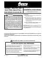
1
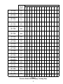
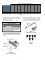
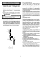
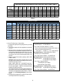
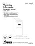
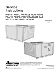
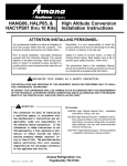
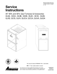
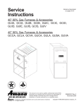
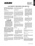
®
Heating ¡ Air Conditioning
A higher standard of comfort
HANG07, HALP09, and
HAC1PS01-HAC1PS14
High Altitude Conversion Kit
WARNING
This conversion kit shall be installed by a
qualified agency in accordance with the
manufacturer’s instructions and all applicable codes and requirements of the authority having jurisdiction. If the information in these instructions is not followed
exactly, a fire, explosion or production of
carbon monoxide may result causing property damage, personal injury or loss of life.
The qualified service agency performing
this work assumes responsibility for the
proper conversion of this appliance with
this kit.
Installation Instructions
Affix this manual, Specification Sheet and Users Information Manual adjacent to the furnace.
KIT INCLUDES:
HANG07 (High Altitude Natural Gas) - installation instructions, orifices, wire ties.
HALP09 (High Altitude Propane Gas) - installation instructions, propane orifices, valve conversion kits
with instructions, conversion rating plate, conversion date certificate, wire ties, and screen/turbulator
removal warning tag.
HAC1PS** (High Altitude Category I Pressure Switch) installation instructions, pressure switch.
IMPORTANT NOTE: These kits are approved for use on
Amana furnace models listed on the following page only. All
of the models listed have an Annual Fuel Utilization Efficiency (AFUE) of 80%.
THE INSTALLATION AND SERVICING OF THIS EQUIPMENT SHOULD BE PERFORMED ONLY BY QUALIFIED,
EXPERIENCED TECHNICIANS.
THIS KIT IS NOT INTENDED FOR USE IN CANADA. THE AMANA 80% FURNACES ARE CGA CERTIFIED TO 4500
FEET ONLY.
!
RECOGNIZE THIS SYMBOL AS A SAFETY PRECAUTION.
ATTENTION INSTALLING PERSONNEL
As a professional installer you have an obligation to
know the product better than the customer. This
includes all safety precautions and related items.
Prior to actual installation, thoroughly familiarize yourself
with this Instruction Manual. Pay special attention to all
safety warnings. Often during installation or repair it is
possible to place yourself in a position which is more
hazardous than when the unit is in operation.
safely and to know it well enough to be able to instruct
a customer in its safe use.
Safety is a matter of common sense...a matter of
thinking before acting. Most dealers have a list of
specific good safety practices...follow them.
The precautions listed in this Installation Manual should
not supersede existing practices but should be
considered as supplemental information.
Remember, it is your responsibility to install the product
July 1998 (2)
Amana
Fayetteville, TN 37334
10759906
I. Description
proper amount of air into the burner. This can cause
incomplete combustion of the gas, flashback, and/or possible yellow tipping.
HANG07, HALP09, and HAC1PS01-14 conversion kits are
required when installing the following units above their
maximum rated altitudes:
In addition to using smaller orifices to reduce the fuel input,
a different pressure switch must be used at altitudes above
the rated altitudes shown in table 1 because of the reduced
air density. This is required regardless of the heat content
of the fuel used.
Amana Air Command 80 SSE
Amana Air Command SSE II
Amana Air Command SSEIIQ
Amana SV furnaces
Amana Packaged Gas/Electric Units:
PGA/B/D**C
II. Pressure Switch Installation
Increases in altitude reduce atmospheric pressure and
oxygen content. These reductions effect operating pressures as well as the amount of oxygen which is available for
combustion. At higher altitudes, the induced draft blower
moves the appropriate CFM with less oxygen and produces
a lower pressure at the pressure tap. To maintain a proper
air to fuel ratio and to provide proper safeguards under
adverse conditions (i.e., blocked flue, blocked drains, etc.),
changes must be made to the unit orifice and pressure
switches. See Table 1 to see what units are affected at
what altitude.
CAUTION
To avoid the risk of fire, property damage,
or personal injury, shut off gas supply first,
then disconnect the electrical supply before
proceeding with conversion.
1. Shut off gas and disconnect electrical supply.
2. Remove pressure switch(es) by removing mounting
screws, disconnecting rubber hose and disconnecting
wiring (see Figure 1 for typical location).
NOTE: Failure to follow these procedures can lead to
inefficient and/or incomplete combustion, exposure to lifethreatening CO and CO2 levels, and possibly premature
heat exchanger failure.
Furnace
Model
GUIA
GUIB
GCIA
GCIB
GUIC
GCIC
GUID
PGA/B/D**C
GUIS
GUIV
GCIS
CAUTION
To avoid the risk of fire, property damage,
or personal injury, if disconnecting wires
on the pressure switch, make certain to
reconnect the wires in the same location.
Rated Altitude
Without Change
Pressure
Switch
Up to
7500 Feet
Up to
6000 Feet
Up to
3000 Feet
Table 1
Figure 1
Pressure Switch
(Typical Location)
The orifices in the high altitude kits have been selected as
a result of testing with the American Gas Association. They
will provide appropriate derating at altitudes above rated
altitudes shown in table 1. The selection is based on nonderated gas (about 1000 BTU/ft 3 for natural gas, and 2500
BTU/ft 3 for propane gas). If your gas supply has been
derated for the altitude, contact your gas supplier for orifice
sizing.
3. Install the required high altitude pressure switch(es).
For single-stage furnaces, see table 2.
For two-stage furnaces (GUIS, GCIS, GUIV), see
table 3.
Do not derate by adjusting the manifold pressure to a lower
pressure setting than what is specified on the furnace
nameplate. With a lower density of air and a lower manifold
pressure at the burner orifice, the orifice will not aspirate the
2
HAC1PS
GUI(A/B)045(A/B)
7501 - 9500 ft
9501 - 11000 ft
GUI(A/B)045(CA/CX)
7501 - 9500 ft
9501 - 11000 ft
Nat. Gas
Derates
(See Sec. V)
01
34±4%
42±4%
X
X
03
04
05
06
07
08
09
10
11
12
34±4%
42±4%
GUI(A/B)070(A/B/CA/CX)
7501 - 9500 ft
9501 - 11000 ft
33±4%
41±4%
GUI(A/B)090(A/B/CA/CX)
7501 - 9500 ft
9501 - 11000 ft
31±4%
38±4%
GUI(A/B)115(A/B/CA/CX)
7501 - 9500 ft
9501 - 11000 ft
27±4%
34±4%
GUI(A/B)140(A/B/CA/CX)
7501 - 9500 ft
9501 - 11000 ft
25±3%
30±3%
GCI(A/B)045(A)
7501 - 9500 ft
9501 - 11000 ft
GCI(A/B)070(A)
7501 - 9500 ft
9501 - 11000 ft
GCI(A/B)090(A)
7501 - 9500 ft
9501 - 11000 ft
GCI(A/B)115(A)
7501 - 9500 ft
9501 - 11000 ft
GCI(A/B)140(A)
7501 - 9500 ft
9501 - 11000 ft
GCI(A/B)045(CA/CX)
7501 - 9500 ft
9501 - 11000 ft
GCI(A/B)070(CA/CX)
7501 - 9500 ft
9501 - 11000 ft
GCI(A/B)090(CA/CX)
7501 - 9500 ft
9501 - 11000 ft
GCI(A/B)115(CA/CX)
7500 - 9500 ft
9500 - 11000 ft
GCI(A/B)140(CA/CX)
7501 - 9500 ft
9501 - 11000 ft
GUIC, GCIC, GUID
6001 - 8500 ft
8501 - 11000 ft
PRESSURE SWITCH
SETTING " WC
02
14
X
X
X
X
X
X
X
X
34±4%
42±4%
X
X
X
X
33±4%
41±4%
X
X
31±4%
38±4%
X
X
27±4%
34±4%
X
25±3%
30±3%
X
X
X
34±4%
42±4%
33±4%
41±4%
13
X
X
X
X
31±4%
38±4%
X
27±4%
34±4%
X
X
25±3%
30±3%
X
X
X
33±2.5%
38±3%
X
X
-1.42 -1.30 -1.20 -1.14 -1.10 -1.05 -1.00 -0.95 -0.89 -0.85 -0.50 -0.41 -1.66 -1.57
Table 2
Pressure Switch Kits (Category I Venting Only)
3
GUIS, GUIV, GCIS High Altitude Charts
GUI(S,V)070
GUI(S,V)090
GUI(S,V)115
GUI(S,V)140
GCIS070
GCIS090
Low Pressure Switch "WC
High Pressure Switch "WC
Natural Gas Orifices (DMS)
HATS01
X
For 3,001 feet to 7,000 feet
HATS02 HATS03 HATS04
HATS05
X
HATS06
X
X
X
For 7,001 to 8,500 feet
HATS07 HATS08 HATS09
X
X
-0.37
-0.66
#44
-0.37
-0.6
#44
-0.37
-0.55
#44
X
-0.32
-0.55
#44
X
X
-0.27
-0.46
#44
-0.32
-0.55
#45
-0.32
-0.46
#45
-0.27
-0.46
#45
X
X
-0.23
-0.37
#45
Table 3
4. Reconnect the hose and wires. Reconnect wiring according to the wiring diagram located inside the blower
compartment access panel.
5. Proceed with orifice installation.
2. Replace natural gas orifices (Figure 3 & 4) with the
correct orifice kit depending on propane or natural gas
usage and the altitude at the installation site. Refer to
Tables 3, 4, and 5 for the appropriate kit required.
Orifices
III. Orifice Installation
CAUTION
To avoid the risk of fire, property damage,
or personal injury, shut off gas supply first,
then disconnect the electrical supply before
proceeding with conversion.
Figure 3
Replacing Gas Orifices
1. Remove the gas manifold by removing the burner box
front cover (not required on all models), cutting the wire
ties, disconnecting the gas valve low voltage wires, and
removing the four manifold mounting screws (see
Figure 2).
Burner Box
Figure 4
Orifices
Front Cover
Manifold
Figure 2
Gas Manifold Removal
4
Furnace
Model
GUIA
GUIB
GCIA
GCIB
GUIC
GCIC
GUID
PGA/B/D**C
Kit
Number
Altitude
(Feet)
Orifice
HANG07
7501 - 11000
#45
Orifice
HANG07
6001 - 11000
Figure 5
Package Unit Orifice
#45
CAUTION
NOTE: Units Installed in Canada are certified to 4500 feet only,
therefore these kits are not applicable in Canada.
To prevent premature heat exchanger
failure, follow the instructions below to
remove all metal inserts from the heat
exchanger tubes during conversions to
propane gas.
Table 4
Natural Gas Orifice Kits*
* This table assumes non-derated natural gas (about 1000
BTU/ft3). If your gas supply has been derated for the
altitude, contact your gas supplier for orifice sizing.
Furnace
Model
Kit
Number
Altitude
(Feet)
Orifice
GUIA
GUIB
GCIA
GCIB
HALP09
7501 - 11000
#56
HALP09
6001 - 11000
#56
HALP09
7001 - 8500
#56
GUIC
GCIC
GUID
PGA/B/D**C
GUIS
GUIV
GCIS
4. If converting to propane gas, remove metal screen
inserts, where present, from the entrance of the heat
exchanger tubes. (See Figure 6 and follow the a,b,c
directions)
NOTE: Some models do not have metal screen inserts.
NOTE: Units Installed in Canada are certified to 4500 feet only,
therefore these kits are not applicable in Canada.
Table 5
Propane Gas Orifice Kits
Figure 6
Removal of Metal Screen Inserts
3. Tighten orifices with a box-end wrench. Do not use a
socket wrench as it could damage the orifices. Do not
overtighten. Do not cross thread.
PGA**C, PGB**C and PGD**C models only:
Remove pilot tube from gas valve.
Remove the screws holding the pilot assembly to the
burner tray.
Remove the assembly.
Remove the pilot orifice as shown in Figure 5.
Replace the pilot orifice with the orifice provided with
the kit, and reassemble in reverse order.
a. Remove entire burner box assembly, including burners, from the partition panel as one unit.
b. Hold assembly and remove the screen retention
plate and tube inserts from each section of the heat
exchanger.
c. Reinstall the retention plate and entire burner box
assembly.
NOTE: To prevent unsatisfactory unit operation, the proper
gas conversion kit must be used for each gas valve. Use the
White-Rodgers kit only with the White-Rodgers gas valve,
the Honeywell Spring kit only with the Honeywell gas valve
and the Robertshaw kit only with the Robershaw gas valve.
THE SPRING KITS ARE NOT INTERCHANGEABLE.
5
CAUTION
NOTE: Two stage furnaces do not require a spring kit.
Discard all spring kits.
To prevent unsatisfactory furnace
operation, the proper gas conversion kit
must be used for each valve. Use the WhiteRodgers spring kit only with the WhiteRodgers gas valve, Honeywell spring kit
only with the Honeywell gas valve and
Robertshaw spring kit only with the
Robershaw gas valve. THE SPRING KITS
ARE NOT INTERCHANGEABLE.
5. Reinstall the gas manifold and reconnect the gas valve
low voltage wiring. Install new wire ties making sure
that wires do not droop between orifices and burners.
6. If converting to propane gas, see PROPANE GAS
CONVERSION section for additional instructions. If
remaining on natural gas, skip to OPERATIONAL
CHECK.
IV. Propane Gas Conversion
IMPORTANT: Propane gas is heavier than air and does not
vent upward as with natural gas fuels.
WARNING
PERSONAL INJURY HAZARD
If your propane gas furnace is installed in
a basement, an excavated area or a
confined space, we strongly recommend
that you contact your propane supplier
about installing a warning device that would
alert you to a gas leak.
Propane gas is heavier than air and any
leaking gas can settle in any low areas or
confined spaces.
Propane gas odorant may fade, making the
gas undetectable except with a warning
device.
An undetected gas leak would create a
danger of explosion or fire. If you suspect
the presence of gas, follow the instructions
on the cover of the furnace installation
manual. Failure to do so could result in
SERIOUS PERSONAL INJURY OR DEATH.
CAUTION
To prevent premature heat exchanger
failure, follow the instructions below to
remove all metal inserts from the heat
exchanger tubes during propane gas
conversions.
1. IMPORTANT: Remove the metal inserts from the
entrance of all heat exchanger tubes, as shown in
Figure 6. This should be done as part of the “ORIFICE
INSTALLATION” procedure.
2. Replace the gas valve regulator spring with one of the
new springs included in this propane gas conversion
kit. If the unit is equipped with a White-Rodgers 36E
gas valve, (Figures 7 & 8), use Spring Kit #92-0659. If
the unit is equipped with a Honeywell VR8205, SV9500,
or SV9501 gas valve, (Figure 9, 12, &13), use Spring
Kit #393691. If the unit is equipped with a Robertshaw
7222 gas valve, (Figure 10), use Spring Kit #54300. In
each case, change the regulator spring per instructions
included with that particular regulator spring. Discard
unused spring kits.
WARNING
NOTE: White-Rodgers 36E96 (Figure 11), gas valves, do
not require a spring kit. Discard all spring kits.
PERSONAL INJURY HAZARD
Iron oxide (rust) can reduce the level of
odorant in propane gas. A gas detecting
device is the only reliable method to detect
a propane gas leak. Contact your propane
supplier about installing a gas detecting
warning device to alert you in the event
that a gas leak should develop.
Failure to detect a propane gas leak could
result in an EXPLOSION or FIRE which
could cause SERIOUS PERSONAL INJURY
OR DEATH.
3. Attach the label (found in the spring kit) to the gas valve,
indicating propane conversion.
4. Attach conversion data plate, with correct input rating,
adjacent to the unit rating plate.
5. Post “conversion date certificate” adjacent to the furnace.
6
Gas Valve
On/Off
Selector
Switch
INLET
High Manifold
Regulator Adjustment
Screw (Under Cap)
O
F
F
M
1
P
3
C
2
PM
C
HI
OUTLET
Inlet
ON
Outlet
OFF
ON
Inlet Pressure Tap
(Side of Valve)
Pressure Regulator
Adjustment
(Under Cap Screw)
Outlet (Manifold)
Pressure Tap
(Side of Valve)
Inlet Pressure Tap
Low Manifold
(Side)
Regulator Adjustment
Gas Valve
Screw (Under Cap)
Control Knob
Figure 7
White-Rodgers 36E22 Gas Valve
Figure 11
White-Rodgers 36E96 Gas Valve
Gas Valve
On/Off
Control Knob
Pressure Regulator
Adjustment (Under
Cap Screws)
INLET
Outlet (Manifold)
Pressure Tap
(Side)
Mates With
Honeywell
Q3450* Pilot
Harness
OUTLET
1/2PSI
Inlet Pressure
Tap
Outlet (Manifold)
Pressure Tap
INLET
OFF
Figure 8
White-Rodgers 36E36 Gas Valve
Pressure Regulator
Adjustment
(Under Cap Screw)
Gas Control/Valve
Knob
Outlet Pressure Tap
Figure 12
Honeywell SV9500 Gas Valve
Outlet (Manifold)
Pressure Tap
Mates With
HONEYWELL
Q3450* Pilot
Harness
Pressure Regulator
Adjustment (Under
Cap Screw)
Honeywell
INLET
OUTLET
ON
Pressure Regulator
Adjustment
(Under Cap Screw)
IN
Inlet Pressure Tap
(Side of Valve)
OUTLET
ON
2
Mates With
Socket Housing
Control Module
Gas Valve
On/Off
Control Lever
In ON Position
INLET
Outlet Pressure Tap
1/8 N.P.T., Plugged
(Steel)
Figure 13
Honeywell SV9501 Gas Valve
Outlet (Manifold)
Pressure Tap
(Side of Valve)
OUTLET
Inlet Pressure Tap
(Side of Valve)
OUTLET
CONTROL
Figure 9
Honeywell VR8205 Gas Valve
ON
OFF
IN
INLET
Gas Valve
On/Off
Control Knob
IGNITOR
PSI
OFF
Inlet Pressure Tap
Pressure Regulator
Adjustment
(Under Cap Screw)
Figure 10
Robertshaw Model 7222
7
5. Check The Manifold Pressure
On single stage units, set the manifold pressure to
10.0” W.C. (water column). For direct vent (GUD,
GCD) furnaces, see “Setting GUD and GCD Manifold
Pressure” before setting pressure (Figure 12).
On two stage units, adjust the high stage manifold
pressure to 10.0” W.C. and the low stage manifold
pressure to 6.0” W.C. (Figure 11). The White-Rodgers
36E96 gas valve requires a 3/32” allen wrench to adjust
the manifold pressures.
A tapped opening is provided in the gas valve (Figures
7 through 13) to facilitate measurement of the manifold
pressure. A "U Tube” manometer having a scale range
from 0 to 12 inches of water column should be used for
this measurement (Figure 14). The manifold pressure
must be measured with the burners operating, and with
the burner box cover (cover not used on all models) in
place.
Single Stage Furnaces
To adjust the pressure regulator, remove the adjustment screw cover on the gas valve. Turn out (counterclockwise) to decrease pressure, turn in (clockwise) to
increase pressure. (“Manifold Pressure Adjustment” in
Figure 7 through 13). Only small variations in gas flow
should be made by means of the pressure regulator
adjustment. For natural gas, the manifold pressure
must be between 3.2 and 3.8 inches water column (3.5”
nominal). For propane gas, the manifold pressure
must be between 9.7 and 10.3 inches water column
(10.0” nominal). Any major changes in flow must be
made by changing the size of the burner orifices.
Two Stage Furnaces
To adjust the pressure regulator, remove both high and
low adjustment screws on the gas valve (Figure 11).
Using a 3/32” allen wrench turn out (counterclockwise)
to decrease pressure, turn in (clockwise) to increase
pressure.
a. Adjust the low stage regulator to increase low stage
output so furnace will light and carryover.
b. Adjust the high stage regulator to required manifold
pressure setting.
c. Reinstall high stage cap screw.
d. Recheck manifold pressure setting with cap on.
e. Adjust low stage regulator to required manifold pressure setting.
f. Reinstall low stage cap screw.
g. Make sure furnace operates at the proper manifold
pressure at both high and low stage outputs.
For propane gas, the manifold pressure must be between 9.7 and 10.3 inches water column (10.0 nominal). The low stage manifold pressure must be between 5.7 and 6.3 inches water column (6.0 nominal).
V. Operational Check
1. Start the furnace using the procedures in the section,
“Operating Your Furnace” in the installation instructions. In addition, perform the following checks and
adjustments.
2. The position of the ignitor, relative to the burner, is not
affected by this conversion procedure but the ignitor
should be visually inspected for any damage at this
point.
3. Check For Leaks - Leak check the orifice threads by
using a soap solution. Reinstall the burner box cover.
WARNING
To avoid the risk of fire or explosion, do not
use a flame to check for leaks.
4. Check Gas Input And Pressures
Check inlet gas pressure. With the power and gas off,
connect a water manometer or adequate gauge to the
“inlet pressure tap” of the gas valve. With the power and
gas on, put the furnace into heating cycle and turn on
all other gas consuming appliances. For natural gas,
the inlet gas pressure should be between 5.0 and 10.0
inches of water. For propane gas the inlet gas pressure
should be between 11.0 and 13.0 inches of water.
Gas Line
Gas Shutoff Valve
Gas Line
To Furnace
Open To
Atmosphere
Drip Leg Cap
With Fitting
Manometer Hose
Manometer
Figure 14
Manometer
8
Natural Gas Input (BTU/hr) at Altitude for GUIC, GUID, GCIC, PGA**C, PGB**C, PGD**C
Heating
Input
(BTU/hr)
46,000
69,000
92,000
115,000
138,000
6,001
feet
6,500
feet
7,000
feet
7,500
feet
8,000
feet
8,500
feet
9,000
feet
9,500
feet
10,000 10,500 11,000
feet
feet
feet
31,970
47,955
63,940
79,925
95,910
31,510
47,265
63,020
78,775
94,530
31,050
46,575
62,100
77,625
93,150
30,590
45,885
61,180
76,475
91,770
31,130
45,195
60,260
75,325
90,390
29,670
44,505
59,340
74,175
89,010
29,348
44,022
58,686
73,370
88,044
28,796
43,194
57,592
71,990
86,388
28,244
42,366
56,488
70,610
84,732
27,692
41,538
55,384
69,230
83,076
27,140
40,710
54,280
67,850
81,420
Table 6
Natural Gas Firing Rates
Low Stage Inputs and High Stage Inputs (BTU/hr) at Altitude
Stage
Low
High
3,001
feet
47,040
64,170
3,500
feet
46,080
62,790
4,000
feet
45,120
61,410
4,500
feet
44,160
60,030
5,000
feet
43,920
59,616
5,500
feet
43,680
59,202
6,000
feet
43,440
58,788
6,500
feet
43,200
58,374
7,000
feet
42,990
57,940
7,001
feet
39,121
52,725
7,500
8,000 feet 8,500 feet
feet
38,621
37,401
36,542
51,567
50,408
49,249
GUI(S,V)090
Low
High
62,720
85,560
61,440
83,720
60,160
81,880
58,880
80,040
58,560
79,488
58,240
78,936
57,920
78,384
57,600
77,832
57,320
77,253
52,161
70,301
51,015
68,755
49,868
67,210
48,722
65,665
GUI(S,V)115
Low
High
78,400 76,800 75,200 73,600 72,200
106,950 104,650 102,350 100,050 99,360
72,800
98,670
72,400
97,980
72,000
97,290
71,650
96,567
65,202
87,876
63,769
85,944
62,336
84,013
60,903
82,082
GUI(S,V)140
Low
High
94,080 92,160 90,240 88,320 87,840 87,360 86,880 86,400 85,980 78,242 76,522
128,340 125,580 122,820 120,060 119,232 118,404 117,576 116,748 115,880 105,451 103,133
74,803
100,816
73,083
98,498
GCIS070
Low
High
47,040
64,170
46,080
62,790
45,120
61,410
44,160
60,030
43,920
59,616
43,680
59,202
43,440
58,788
43,200
58,374
42,990
57,940
39,121
52,725
38,261
51,567
37,401
50,408
36,542
49,249
GCIS090
Low
High
62,720
85,560
61,440
83,720
60,160
81,880
58,880
80,040
58,560
79,488
58,240
78,936
57,920
78,384
57,600
77,832
57,320
77,253
52,161
70,300
51,015
68,755
49,868
67,210
48,722
65,665
Model
GUI(S,V)070
Table 7
6. Check The Gas Input - Natural Gas
To measure the gas input using the gas meter, proceed
as follows:
a. Turn off gas supply to all other appliances except the
furnace.
b. With the furnace operating, time the smallest dial on
the meter for one complete revolution. If this is a 2
cubic foot dial, divide the seconds by 2; if it is a 1 cubic
foot dial, use the seconds as is. This gives the
seconds per cubic foot of gas being delivered to the
furnace.
c. INPUT = (GAS HTG VALUE) x (3600) ÷ (SEC. PER
CUBIC FOOT)
Example: Natural gas with a heating value of 1000
BTU per cubic foot and 34 seconds per cubic foot as
determined by Step 2, then:
Input = 1000 x 3600 ÷ 34 = 106,000 BTU per Hour
NOTE: BTU content of the gas should be obtained
from the gas supplier. (3600 is a conversion factor
between seconds and hours).
This measured input must agree with the derates for
the furnace model, input, and installation altitude as
indicated in the appropriate tabel (Table 2, Table 6,
or Table 7). See Derating Examples 1-4 for use of
tables.
d. Relight all other appliances turned off in Step 6a. Be
sure all pilot burners are operating.
Derating Example 1: GUIA115A40 at 8500 ft.
Sea level input = 115,000 BTU/Hr.
From Table 2: Derate at 8500 ft. = 27±4%
Since we are at the mid point of the elevation range, we
use the mid point of the derate; 27%.
New Input = 115000 x (1 - .27) = 83950 BTU/hr
Derating Example 2: GUIC045DA30 at 7500 ft.
Sea level input = 46,000 BTU/hr
From Table 6 rate at 7500 ft. = 30,590 BTU/hr
Derating Example 3: GUIS115CA50 at 4500 ft.
Sea level input =
80,000 BTU/hr (Low Stage)
115,000 BTU/hr (High Stage)
From Table 7 rates at 4500 ft.=
73,600 BTU/hr (Low Stage)
100,050 BTU/hr (High Stage)
Derating Example 4: PGB36C0902D at 6500 ft.
Sea level input = 92,000 BTU/hr (High Stage)
From Table 6 rate at 6500 ft.= 63,020 BTU/hr
9
7. Check The Gas Input - Propane Gas
Verify the gas input rate by checking that the appropriate orifices have been installed and the manifold pressure has been set as stated in these instructions.
8. Check Burner Flames
Check burner flames through the view port in the
burner box. Flames should be stable, soft and blue,
(dust may cause orange tips but they must not be
yellow). They should extend directly outward from the
burners without curling, floating, or lifting off.
9. Check the normal operating sequence of the ignition
system to insure burners light properly.
10. Check Temperature Rise
NOTE: The relationship between external static pressure and temperature rise will be different than is
shown in the Installation Instructions, while the relationship between CFM and temperature rise will be
about the same. Temperature rise must still be within
the limits on the nameplate.
Check the temperature rise through the unit by placing
thermometers in supply and return air registers as
close to the furnace as possible. Thermometers must
not be able to “see” the furnace’s heat exchangers, or
false readings could be obtained.
• All registers must be open, all duct dampers must
be in their final (fully or partially open) position, and
the unit operated for 15 minutes before taking readings.
• The temperature rise for each heating speed must
be within the range specified on the rating plate or
Specification Sheet.
NOTE: Air temperature rise is the temperature difference between supply and return air.
With a properly designed system, the proper amount of
temperature rise will normally be obtained when the
unit is operated at rated input with the “as shipped”
blower speed.
If the correct amount of temperature rise is not obtained, it may be necessary to change the blower
speed. A faster blower speed will reduce the temperature rise. A slower blower speed will increase the
temperature rise.
If it is necessary to adjust the blower speed, consult the
furnace installation manual for details.
11. For propane gas conversions, attach conversion data
plate, with correct input rating, adjacent to the unit
rating plate and post “conversion date certificate” adjacent to the furnace.
VI. Complete The Installation
See the furnace installation manual for all installation details
which were not covered in this booklet.
10