1
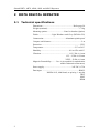
Instruction manual
Simrad DR76, AR78, AR80,
AR81 and AR83
Digital, Analog and Bearing Repeaters
English
www.simrad-yachting.com
A brand by Navico - Leader in Marine Electronics
INSTRUCTION MANUAL
Instruction manual
DR76 Digital repeater,
AR78/AR80 Analog repeaters
and
AR81/AR83 Bearing repeaters
This manual is used for installing and operating Simrad’s
Digital -, Analog- and Bearing Repeaters.
20221487 / B
i
Simrad DR76, AR78, AR80, AR81 and AR83 Repeaters
Document revisions
Rev
Date
A
11.11.03
B
02.09.04
Written by
Checked by
Approved by
Document history
Rev. A First issue
Rev. B Updated to include AR81 and AR83 Bearing repeaters.
About this manual
This manual provides installation instructions, operation and simple fault finding
procedures for Simrad’s repeaters.
The manual must be used in conjunction with the instructions and drawings designed
for the specific vessel, and should remain with the vessel on completion of the
installation to serve as an additional reference during maintenance of the system.
Important text that requires special attention from the reader is emphasized as follows:
Note
Used to draw the reader’s attention to a comment or some
important information.
Caution
Used for warning the reader that a risk of damage to the
equipment exists if care is not exercised.
WARNING
Used for warning the reader that a risk of
damage to the equipment exists if care is not
exercised.
To assist us in making improvements to this manual, we would welcome comments and
constructive criticism. Please send all such - in writing to:
Simrad Egersund AS
Nyåskaien
P.O. Box 55
N-4379 Egersund, Norway
or by e-mail to:
[email protected]
ii
20221487 / B
INSTRUCTION MANUAL
Table of contents
1
INTRODUCTION ................................................................1
2
DR76 DIGITAL REPEATER .................................................2
2.1
Technical specifications .................................................................................2
2.2
Installation ......................................................................................................3
Panel mounting ......................................................................................................... 3
Optional bracket mounting ....................................................................................... 4
3
2.3
Cable connection ............................................................................................5
2.4
Operation ........................................................................................................6
2.5
Commissioning ...............................................................................................8
2.6
Fault finding ...................................................................................................8
AR78/80 ANALOG REPEATERS ..........................................9
3.1
Technical specifications .................................................................................9
3.2
Installation ....................................................................................................10
Panel mounting ....................................................................................................... 10
Optional bracket mounting ..................................................................................... 10
3.3
Cable connection ..........................................................................................11
3.4
Operation ......................................................................................................12
Turning the repeater ON......................................................................................... 12
Adjusting display illumination ............................................................................... 12
4
3.5
Commissioning .............................................................................................13
3.6
Fault finding .................................................................................................13
AR81/83 BEARING REPEATERS.......................................14
4.1
Technical specifications ...............................................................................14
4.2
Installation ....................................................................................................15
4.3
Cable connection and DIP switch settings ...................................................15
Dip settings in AR81/83 repeater ........................................................................... 15
Connecting an AR81/83 repeater to a GC80/85 Compact gyro system ................. 17
Connecting an AR81/83 repeater to a GC80/85 Expanded/Dual gyro system ....... 19
4.4
Operation ......................................................................................................23
Turning the repeater ON......................................................................................... 23
Adjusting display illumination ............................................................................... 23
4.5
Commissioning .............................................................................................23
4.6
Fault finding .................................................................................................24
20221487 / B
ii
Simrad DR76, AR78, AR80, AR81 and AR83 Repeaters
5
SPARE PART LIST............................................................25
6
DRAWINGS .....................................................................27
iii
20221487 / B
INSTRUCTION MANUAL
1 INTRODUCTION
The DR76 Digital Repeater, the AR78/AR80 Analog repeaters,
and AR81/AR83 Bearing repeaters have been designed to accept
a variety of digital inputs that are sensed when first switching on
the repeater.
The repeaters accept serial data (RS422). The D-type connector
has pins allocated for power and serial data.
The serial input is configured to recognize NMEA 0183 HDT,
HDG and HDM sentence structures in priority order.
All repeaters may be delivered with an optional mounting
bracket.
The repeaters should be mounted where it is most convenient for
the user, with regard to the unit’s environmental protection,
temperature range and cable length. The unit should not be
installed in area exposed to heavy vibrations.
Avoid mounting the repeater where it is easily exposed to
sunlight, as this will shorten the lifetime of the display.
20221487 / B
1
Simrad DR76, AR78, AR80, AR81 and AR83 Repeaters
2 DR76 DIGITAL REPEATER
2.1
Technical specifications
Dimensions ............................................................. Refer page 28
Weight (nominal):................................................................1.2 kg
Mounting options:.................................Panel or bracket (Option)
Finish: .......................... Light Weather-work Grey (BS3816-676)
Construction:............................................Aluminum splash proof
Compass safe distance .............................................................2 m
Protection:.............................................................................. IP33
Temperature:.............................................................-5°C to 50°C
Humidity: ........................................................0% to 95% at 40°C
Vibration: ....................................................... 1-12.5 Hz ±1.6 mm
12.5 – 25 Hz ±0.38 mm
25HZ – 50 Hz ±0.1 mm
Magnetic Permeability:........ Cat. A (Acceptable for embarkation
within volumetric allowances)
Power supply: ...................................................... 24V DC, 0.75A
Data input: ..........................................................................RS422
NMEA 0183, 4800 baud, no priority, 1 stop bit
HDT
HDG
HDM
2
20221487 / B
INSTRUCTION MANUAL
2.2
Installation
Panel mounting
Note
1
Drill 4 mounting holes and make a panel cut-out according
to supplied drilling template
2
Use the supplied screws to fasten the control unit to the
panel
Do not over- tighten the mounting screws!
3
20221487 / B
Apply the front panel corners
3
Simrad DR76, AR78, AR80, AR81 and AR83 Repeaters
Optional bracket mounting
Numbers in brackets refer to the drawing below.
1
Locate the cradle (1) on the mounting site and mark 4
holes for the fixing screws on the mounting surface
2
Drill the 4 mounting holes and screw the cradle to the
mounting surface
3
Insert the 2 open ratchet disks (2) into the cradle
4
Use the 4 supplied screws (3) to fasten the DR76 to the
left and right brackets (4)
5
Apply the front panel corners (5)
6
Insert the 2 closed ratchet disks (6) into the left and right
brackets
7
Use the locking knobs (7) to assemble the cradle with the
left and right brackets
8
Adjust the repeater to best viewing angle
5
3
4
5
6
3
7
5
4
3
6
2
2
1
7
4
20221487 / B
INSTRUCTION MANUAL
2.3
Cable connection
Caution
Any voltage supplies other than those specified in the product
specification, page 2, may cause damage to the repeater.
The repeaters have no power switch, and the repeater will be
automatically started when the cable is connected to the unit. It
is therefore recommended to connect the cable via an external
power switch.
The repeaters are designed to run on 24VDC, and accept a
digital RS422 data signal.
The repeater is supplied with a 2.5 meters cable with a 15 pins
female D-type connector.
The following table indicates the function of cores and their
identification.
Function
D-type
connector pin
Wire color
(as supplied)
24V DC
1
Red
DC Return
9
Black
Data positive (TDA)
3
Green
Data negative (TDB)
11
Blue
Screen
8
Green/Yellow
20221487 / B
Ships cable
(to be filled out for
reference by installer)
5
Simrad DR76, AR78, AR80, AR81 and AR83 Repeaters
2.4
Operation
TURN INDICATOR
TRUE
DIM
BAR
DIM
SET
DIGIT
HEADING
SIMRAD DR76
The DR76 front panel includes the following elements:
• Horizontal Turn indicator
TURN INDICATOR
- used either as a rate of turn indicator, or as a
steering indicator to indicate the difference
between actual and set course
TRUE
• Heading display
- showing the input heading received from the
transmitting device, e.g. the Gyro compass
HEADING
• Dimmer buttons
DIM
BAR
DIM
DIGIT
SET
- used for adjusting the illumination on the turn
indicator or the back light intensity for the
heading display
• SET button
- used for setting a course to steer, and for setting
the display mode for the turn indicator
Turning the DR76 ON
DR76 has no separate power button, and the unit is
automatically turned on when the cable is connected to the unit.
The repeater has been designed to accept a variety of NMEA
input sentences. When the cable is connected to the repeater, it
will automatically sense which sentence that is present. The
following priority is used when defining the signal:
- True heading (HDT)
- Heading & Variation format (HDG)
- Old Heading format (HDM)
6
20221487 / B
INSTRUCTION MANUAL
If the signal is invalid or missing after 1 second, this will be
indicated with flashing heading display.
When the defined input signal is lost, power must be switched
off and on again. If the cable not is connected via an external
switch, the cable must be disconnecting and reconnected again
to define a new input signal.
Adjusting display illumination
The display illumination on both displays may be adjusted by
using the dimmer buttons.
DIM
BAR
DIM
DIGIT
DIM BAR button is used for adjusting the illumination on the
Turn indicator.
DIM DIGIT button is used for adjusting the back lighting on the
Heading display.
When a dimmer buttons is pressed, the illumination will be
increased/decreased until the button is released.
Display modes for Turn indicator
DR76’s Turn indicator may be set to 3 different display modes,
defined as Mode 0, 1 and 2.
Mode 0:
Rate of turn indicator with fine resolution. For each 1/10°
the vessel’s bow turns, three bargraphs will move to left or
right on the indicator.
TURN INDICATOR
Mode 1:
As for Mode 0, but with the bargraphs indicating each 1°
turn.
Mode 2:
In this mode the Turn indicator acts as a set steering
display. When the vessel’s heading is identical to set
course, all LEDs are unlit. For each degree steered offcourse, one LED will be lit.
TURN INDICATOR
20221487 / B
7
Simrad DR76, AR78, AR80, AR81 and AR83 Repeaters
Setting the Display mode
DIM
BAR
SET
Active mode is selected by pressing the SET button and the DIM
BAR button simultaneously.
The last digit in the heading display will now cycle between the
three display modes. Then selected mode is indicated, this mode
is activated by releasing both buttons.
2.5
Commissioning
Perform the following tests when commissioning the repeater:
1
Ensure that the mechanical installation and cable
connection has been completed according to the
description on previous pages
2
Connect the cable to the repeater. The repeater will
automatically sense which digital signal that is present
- The repeater will align itself to zero and then to the
transmitted gyro heading
3
2.6
Ensure that the lighting is set to a suitable level. Adjust if
necessary with the dimmer button
Fault finding
The DR76 is a sealed unit, and breakage of the security seal will
invalidate the warranty.
If trouble is encountered, make preliminary checks as described
below. If the problems remain unsolved, contact your nearest
Simrad dealer for assistance.
Symptom
Probable fault
Remedy
The repeater does not
operate.
No power or incorrect power
connection.
Check incoming power
supply.
The repeater aligns itself
to zero and does not
respond to heading
input.
The digital signal to the repeater is
either not present, or the sentence
being sent is incorrect or has wrong
polarity.
Switch the unit off and on
again.
Lighting not visible
Damage to internal LED, or
damage to internal PCB.
Return to Simrad dealer for
service.
8
20221487 / B
INSTRUCTION MANUAL
3 AR78/80 ANALOG REPEATERS
3.1
Technical specifications
Dimensions: ................................................ Refer page 29 and 30
Weight (nominal):
AR78:................................................................2.9 kg
AR80 .................................................................1.9 kg
Mounting: .............................................Panel or bracket (Option)
Finish: ..................................................... Satin black (RAL 9005)
Construction:................................................ Aluminum enclosure
Connections: .......1x6 way screened cable (15 way D-type fitted)
Compass safe distance: ............................................................2 m
Cable: ................................... 2.5 m tailed with D-Type connector
Protection:.............................................................................. IP54
Temperature:.......................................................... -5°C to +50°C
Performance:
AR78:.................................................................±0.5°
AR80:.................................................................±0.1°
Follow up rate: ...................................................................... 12°/s
Dial Resolution:
AR78:.................................................... Marked to 1°
AR80:
Outer dial:.................................... Marked to 1°
Inner dial: ................................. Marked to 0.1°
Power supply: ...................................................... 24V DC, 0.75A
Data input: ..........................................................................RS422
NMEA 0183, 4800 baud, no priority, 1 stop bit
HDT
HDG
HDM
20221487 / B
9
Simrad DR76, AR78, AR80, AR81 and AR83 Repeaters
3.2
Installation
Panel mounting
Note
1
Drill the mounting holes and make a panel cut-out
according to supplied drilling template
2
Use the supplied screws to fasten the control unit to the
panel
Do not over- tighten the mounting screws!
3
Apply the front panel corners
Refer the drawing on page 3 showing the panel mounting for
DR76.
Optional bracket mounting
Numbers in brackets refer to the drawing below.
1
Locate the bracket (1) on the mounting site and mark 5
holes for the fixing screws on the mounting surface
2
Drill the 5 mounting holes and screw the bracket to the
mounting surface
3
Insert the 2 open ratchet disks (2) into the bracket
4
Insert the 2 closed ratchet disks (3) into the repeater
5
Use the locking knobs (4) to assemble the brackets and the
repeater
6
Adjust the repeater to the best viewing angle
3
4
3
2
4
2
1
10
20221487 / B
INSTRUCTION MANUAL
3.3
Cable connection
Caution
Any voltage supplies other than those specified in the product
specification, page 9, may cause damage to the repeater.
The repeaters have no power switch, and the repeater will be
automatically started when the cable is connected to the unit. It
is therefore recommended to connect the cable via an external
power switch.
The repeaters are designed to run on 24VDC, and accept a
digital RS422 data signal.
The repeater is supplied with a 2.5 meters cable with a 15 pins
female D-type connector.
The following table indicates the function of cores and their
identification.
Function
D-type
connector pin
Wire color
(as supplied)
24V DC
1
Red
DC Return
9
Black
Data positive (TDA)
3
Green
Data negative (TDB)
11
Blue
Screen
8
Green/Yellow
20221487 / B
Ships cable
(to be filled out for
reference by installer)
11
Simrad DR76, AR78, AR80, AR81 and AR83 Repeaters
3.4
Operation
DIM
SIMRAD AR 80
The analog repeaters include a rotating dial and a dimmer
button.
Turning the repeater ON
The repeaters have no separate power button, and the unit is
automatically turned on when the cable is connected to the unit.
The repeaters have been designed to accept a variety of NMEA
input sentences. When the cable is connected to the repeater, it
will automatically sense which sentence that is present. The
following priority is used when defining the signal:
- True heading (HDT)
- Heading & Variation format (HDG)
- Old Heading format (HDM)
If the signal is invalid or missing after 1 second, the repeater
will indicate this by flashing illumination and by rotating the
dial back and forth +/-35° around the last known heading.
When the defined input signal is lost, the power must be
switched off and on again. If the cable not is connected via an
external switch, the cable must be disconnecting and
reconnected again to define a new input signal.
Adjusting display illumination
The rotary button is used for adjusting the background
illumination on AR78 and AR80. Rotating the button in a
clockwise direction will increase the light intensity, while the
light intensity will be decreased when the button is turned
counter-clockwise.
12
20221487 / B
INSTRUCTION MANUAL
3.5
Commissioning
Perform the following tests when commissioning the repeater:
7
Ensure that the mechanical installation and cable
connection has been completed according to the
description on previous pages
8
Connect the cable to the repeater. The repeater will
automatically sense which digital signal that is present
- The repeater will align itself to zero and then to the
transmitted gyro heading
9
3.6
Ensure that the lighting is set to a suitable level. Adjust if
necessary with the dimmer button
Fault finding
The AR68/AR77 are sealed units, and breakage of the security
seal will invalidate the warranty.
If trouble is encountered, make preliminary checks as described
below. If the problems remain unsolved, contact your nearest
Simrad dealer for assistance.
Symptom
Probable fault
Remedy
The repeater does not
operate.
No power or incorrect power
connection.
Check incoming power
supply.
The repeater aligns itself
to zero and does not
respond to heading
input.
The digital signal to the repeater is
either not present, or the sentence
being sent is incorrect or has wrong
polarity.
Switch the unit off and on
again.
Damage to internal LED, or
damage to internal PCB.
Return to Simrad dealer for
service.
The dial rotates +/- 35°.
Lighting not visible
20221487 / B
13
Simrad DR76, AR78, AR80, AR81 and AR83 Repeaters
4 AR81/83 BEARING REPEATERS
4.1
Technical specifications
Dimensions: ............................................................ Refer page 31
Weight (nominal):................................................................4.5 kg
Mounting: ...........................................Dedicated holders or stand
Connections: ...................................................Via holder or stand
Compass safe distance: .........................................................0.5 m
Cable: ....................................................................................1.8 m
Protection:.............................................................................. IP66
Temperature:........................................................ -20°C to +60°C
Performance:.........................................................................±0.3°
Follow up rate: ..................................................... 40°/s maximum
Dial Resolution:
AR81: ................................................... Marked to 1°
AR83:
Outer dial..................................... Marked to 1°
Inner dial................................... Marked to 0.5°
Power supply: .................................................................. 24V DC
Data input: .....................................................................$ - - HDT
14
20221487 / B
INSTRUCTION MANUAL
4.2
Installation
The AR81/AR83 bearing repeaters have to be mounted by using
one of the repeater holders or in the repeater stand. Refer
SPARE PART LIST, page 25.
Refer dimensional drawings for repeater holders and repeater
stand, page 32 onwards.
4.3
Cable connection and DIP switch settings
Caution
Any voltage supplies other than those specified in the product
specification, page 14, may cause damage to the repeater.
The AR81/AR83 repeaters are supplied with a 1.8 m cable.
The repeater is connected to the gyro compass via the connection
box on the repeater holder or on the repeater stand.
Refer the following paragraphs for how to connect the repeater
and how to set necessary jumpers in repeater and in the gyro’s
control unit.
Dip settings in AR81/83 repeater
DIP switch settings in the AR81/83 repeaters are factory set for
connection to a GC80/85 gyro compass.
If the repeaters are to be used by any other gyro system, it could
be necessary to set the DIP switches in S1 according to the
description following here.
8
ON
1
S1
20221487 / B
8
ON
S2
1
S3
15
Simrad DR76, AR78, AR80, AR81 and AR83 Repeaters
8
SWITCH
DEFAULT
S1-1
ON
FUNCTION
DESCRIPTION
1-1 OFF
1-2 OFF
ON
20 msec
(IEC-2)
1-3 OFF
1
1-1 ON
S1
1-2 OFF
S1-2
OFF
100 msec
(IEC-1)
1-3 OFF
Setup for
receive
format
1-1 OFF
1-2 ON
200 msec
(IEC-1)
1-3 OFF
1-1 ON
S1-3
OFF
1-2 ON
1 sec
(IEC-1)
1-3 OFF
1-1 OFF
1-2 OFF
TK format
1-3 ON
8
ON
1
S3
16
S1-4
OFF
Not used
S1-5
OFF
Not used
S1-6
OFF
Repeater
type
S1-7
-
Polarity for
offset
ON
Software
update
OFF = Software update
S1-8
SWITCH
DEFAULT
FUNCTION
DESCRIPTION
S2
-
Offset value
SWITCH
DEFAULT
FUNCTION
S3-1
OFF
S3-2
OFF
S3-3
OFF
S3-4
OFF
S3-5
OFF
S3-6
OFF
S3-7
OFF
S3-8
OFF
OFF = Standard
ON = Steering repeater
OFF = +
ON = -
Value input
with S2
ON = Normal operation
DESCRIPTION
Not used
20221487 / B
INSTRUCTION MANUAL
Connecting an AR81/83 repeater to a
GC80/85 Compact gyro system
The AR81/83 should be connected to one of the four TX ports in
the Compact control unit as shown on the figure below:
GC80/85
COMPACT
CONTROL UNIT
REPEATER HOLDER /
REPEATER STAND
CONNECTION BOX
TB1
1TX+
1TX1TSC
1R241R24+
2TX+
2TX2TSC
2R242R24+
3TX+
3TX3TSC
3R243R24+
4TX+
4TX4TSC
4R244R24+
29
30
31
32
33
34
35
36
37
38
39
40
41
42
43
44
45
46
47
48
*
AR81/AR83
BEARING
REPEATER
1.8m
BLACK
WHITE
RED
GREEN
YELLOW
BROWN
1
2
3
4
5
TX+
TX-
11
12
13
14
15
16
IEC-H
IEC-L
Vcc
DIM-AN
24V
24C
R24R24+
* Cable not supplied by Simrad
20221487 / B
17
Simrad DR76, AR78, AR80, AR81 and AR83 Repeaters
ICIF board
F3
F2
F4
F1
F5
F8
TB2
TB3
When an AR81/83 is connected to a GC80/85 Compact gyro
system, the serial output signal from the gyro has to be set to
IEC-61162-1 ed.2. This is done by setting a jumper on the ICIF
board in the GC80/85 Compact Control unit. Depending on
which TX port that is used for connecting the repeater, pin 1-2
has to be shortened on the following jumpers on the ICIF board:
F6
F9
F7
TX PORT
JUMPER
1TX
J7, 3-4 short
2TX
J8, 3-4 short
3TX
J9, 3-4 short
4TX
J10, 3-4 short
Refer to the manual for your gyro system for more detailed
information about the different jumper settings.
18
20221487 / B
INSTRUCTION MANUAL
Connecting an AR81/83 repeater to a
GC80/85 Expanded/Dual gyro system
10 TX channels are available when connecting the AR81/83
repeater to a GC80/85 Expanded or Dual gyro system. The
repeater should be connected to the control unit as shown on the
figure below:
GC80/85
EXPANDED / DUAL
CONTROL UNIT
REPEATER HOLDER /
REPEATER STAND
CONNECTION BOX
TB2
1TX+
1TX1TSC
1R241R24+
2TX+
2TX2TSC
2R242R24+
3TX+
3TX3TSC
3R243R24+
4TX+
4TX4TSC
4R244R24+
5TX+
5TX5TSC
5R245R24+
6TX+
6TX6TSC
6R246R24+
7TX+
7TX7TSC
7R247R24+
8TX+
8TX8TSC
8R248R24+
1
2
3
4
5
6
7
8
9
10
11
12
13
14
15
16
17
18
19
20
25
26
27
28
29
30
31
32
33
34
35
36
37
38
39
40
41
42
43
44
*
1
2
3
4
5
TX+
TX-
11
12
13
14
15
16
IEC-H
IEC-L
Vcc
DIM-AN
24V
24C
R24R24+
TB1
9TX+
9TX9TSC
9R249R24+
10TX+
10TX10TSC
10R2410R24+
27
28
29
30
31
32
33
34
35
36
AR81/AR83
BEARING
REPEATER
1.8m
* Cable not supplied by Simrad
20221487 / B
BLACK
WHITE
RED
GREEN
YELLOW
BROWN
19
Simrad DR76, AR78, AR80, AR81 and AR83 Repeaters
When an AR81/83 is connected to a GC80/85 Expanded or Dual
gyro system, the serial output signal from the gyro has to be set
to IEC-61162-1 ed.2. This is done by setting a jumper on the
SCC or SIFC board in the GC80/85 Expanded, or on the SCC
or SCOIF board in the Dual control unit.
Depending on which TX port that is used for connecting the
repeater, the jumpers have to be set as described in the following
pages.
GC80/85 Expanded gyro system
TX PORT
BOARD
1TX
SIFC
board
J7, 5-6 short
SCC
2TX
SCC
board
JUMPER
J8, 3-4 short
3TX
J6, 3-4 short
4TX
J7, 3-4 short
5TX
J8, 3-4 short
6TX
J9, 3-4 short
SIFC
7TX
J10, 3-4 short
8TX
J11, 3-4 short
9TX
J12, 3-4 short
10TX
J13, 3-4 short
SCC board
2
1
J7
J8
6
5
2
4
1
3
J8
20
2
1
6
5
2
4
1
3
J7
20221487 / B
INSTRUCTION MANUAL
SIFC board
J27
J26
J13
J12
J11
J10
J9
J8
J7
J6
J13
J12
J11
J10
J9
J8
J7
J6
Refer to the manual for your gyro system for more detailed
information about the different jumper settings.
GC80/85 Dual gyro system
TX PORT
1TX
SCC
board 2
SCC
board 1
SCOIF
board
20221487 / B
2TX
BOARD
SCC
JUMPER
J7, 5-6 short
J8, 3-4 short
3TX
J15, 3-4 short
4TX
J16, 3-4 short
5TX
J17, 3-4 short
6TX
7TX
J37, 3-4 short
SCOIF
J38, 3-4 short
8TX
J39, 3-4 short
9TX
J40, 3-4 short
10TX
J41, 3-4 short
21
Simrad DR76, AR78, AR80, AR81 and AR83 Repeaters
SCC board
2
J7
J8
6
5
2
4
1
3
2
1
6
5
2
4
1
3
J7
1
J8
SCOIF board
J38 31
3
J39 1
3
J40 1
3
J41 1
J38
J24 6
5
1
2
4
2
4
2
4
2
4
2
J22 31
J41 31
J43 31
J42 13
4
2
4
2
4
2
4
2
J35
J34
J29
J30
J26
J23
J25
J39
J40
J41
2
4
2
4
2
4
2
1
3
1
3
1
3
2
4
2
4
2
4
1
3
1
3
1
3
12
1
2
12
1
2
4
12
34
1
3
2
1
S1
J20 24 13 24
J18 2 1 2
J43 24 13 24
J42 24 13 24
J45 24 13 24
J44 24 13
J37 24 13
1
3
1
1
3
1
3
1
3
J36
J28
J33
J32
J31
J27
J21
J19
J16
J17
J15
SCOIF board
2
4
2
4
2
4
J37 24
22
1
3
1
3
1
3
J16
J17
J15
1
3
20221487 / B
INSTRUCTION MANUAL
4.4
Operation
Turning the repeater ON
The repeater holders and the repeater stand have a power button
on the connection box.
When the cables are connected and the jumper set in the control
unit according to the previous pages, the repeater is turned on by
switching the power button.
If the signal is invalid or missing after 1 second, the repeater will
indicate this by rotating the dial back and forth +/-35° around the
last known heading.
DIMMER
POWER
When the defined input signal is lost, the power must be
switched off and on again. If the cable not is connected via an
external switch, the cable must be disconnecting and
reconnected again to define a new input signal.
Adjusting display illumination
The rotary button is used for adjusting the illumination on
AR81/83 repeater. Rotating the button in clockwise direction
will increase the light intensity, while the light intensity will be
decreased when the button is turned counter-clockwise.
4.5
Commissioning
Perform the following tests when commissioning the repeater:
1
Ensure that the mechanical installation and cable
connection has been completed according to the
description on previous pages
2
Turn the repeater on.
- The repeater will align itself to zero and then to the
transmitted gyro heading
3
20221487 / B
Ensure that the lighting is set to a suitable level. Adjust if
necessary with the dimmer button
23
Simrad DR76, AR78, AR80, AR81 and AR83 Repeaters
4.6
Fault finding
The AR81/83 are sealed units, and breakage of the security seal
will invalidate the warranty.
If trouble is encountered, make preliminary checks as described
below. If the problems remain unsolved, contact your nearest
Simrad dealer for assistance.
Symptom
Probable fault
Remedy
The repeater does not
operate.
No power or incorrect power
connection.
Check incoming power
supply.
The repeater aligns itself
to zero and does not
respond to heading
input.
The digital signal to the repeater is
either not present, or the sentence
being sent is incorrect or has wrong
polarity.
Switch the unit off and on
again.
24
Check the sentence from the
heading sensor.
20221487 / B
INSTRUCTION MANUAL
5 SPARE PART LIST
The following tables list part numbers for all standard and
optional equipment that may be delivered for DR76, AR78,
AR80, AR81 and AR83 repeaters.
Part no
Description
27103365
DR76 Digital repeater
27103340
AR78 Analog repeater
27103324
AR80 Analog repeater
27101732
Single scale Bearing Repeater NMEA.
To be mounted in BB holder, MB Holder or BH stand. IMO
A424
27101740
Dual scale Bearing Repeater NMEA.
To be mounted in BB holder, MB Holder or BH stand. IMO
A424
27103407
Repeater mounting accessories for DR76 and AR78/AR80.
Including 4 front panel corners and 4 screws
44170702
2.5 m Repeater cable with plug
22084941
DR76 Mounting bracket
27103589
AR78 Mounting bracket
20221487 / B
25
Simrad DR76, AR78, AR80, AR81 and AR83 Repeaters
Part no
Description
27103571
AR80 Mounting bracket
27102870
AR81/AR83 Repeater Holder
Gimballed bracket for indoor mounting of bearing repeater
27103076
AR81/AR83 Repeater Holder.
Trunnion bracket for bearing repeater
27102862
AR81/AR83 Repeater Stand
Binnacle for outdoor mounting of bearing repeater.
27102888
AR81/AR83 Azimuth Circle
Used on bearing repeater to take bearings on celestial bodies
and surface targets etc.
27102912
Course Recorder
Records day, hour and course.
26
20221487 / B
INSTRUCTION MANUAL
6 DRAWINGS
The following drawings are enclosed:
Drawing name
Note
20221487 / B
Drawing no.
Rev.
DR76 Digital repeater. Dimensions
D2-710354
A
AR78 Analog repeater. Dimensions
D2-710355
A
AR80 Analog repeater. Dimensions
D2-710356
A
AR81/AR83 Bearing repeater. Dimensions
N4-710302
A
AR81/AR83 Repeater holder (BB). Dimensions
N4-710303
-
AR81/AR83 Repeater holder (BH) Dimensions
N4-710304
-
Repeater stand (BH). Dimensions
N4-710308
-
The original signed drawings are recorded at Simrad Egersund.
27
Simrad DR76, AR78, AR80, AR81 and AR83 Repeaters
28
20221487 / B
INSTRUCTION MANUAL
20221487 / B
29
Simrad DR76, AR78, AR80, AR81 and AR83 Repeaters
30
20221487 / B
INSTRUCTION MANUAL
20221487 / B
31
Simrad DR76, AR78, AR80, AR81 and AR83 Repeaters
32
20221487 / B
INSTRUCTION MANUAL
20221487 / B
33
Simrad DR76, AR78, AR80, AR81 and AR83 Repeaters
Simrad Robertson AS
EGERSUND
NORWAY
BH Repeater Stand
Dimensions
1
34
1
N4 - 710308 20221487 / B
DR76, AR78, AR80, AR81 and AR83 Repeaters Manual EN, Doc.no.20221487, Rev.B