1
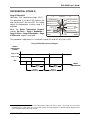
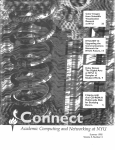
Combined Ventilation Controller
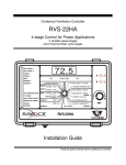
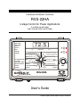
RVS-22HA
4-stage Control for Power Applications
2 variable speed stages
and 2 thermo/mister cycle stages
72.5
VAR STAGE 1
VAR STAGE 2
STAGE 3
A
STAGE 4
MIST
ROOM TEMP.
MIN
MAX
HEATER 1
HEATER 2
B
ALARM OFFSETS
HEAT 1
HEAT 2
RH COMPENSATION
T° CURVE
MIN. SPEED CURVE
DEFECTIVE PROBE
MIST
OFFSET / DIFF.
CURRENT RAMPING DAY
OFFSET / DIFF.
MIN. SPEED / CURVE
OFFSET / DIFF.
BANDWIDTH / TIMER
STAGE 1
HUMIDITY MIN / MAX
ON (SEC.)
TIMER OFF (MIN.)
STAGE 3
ALARM
LOCKED
SET POINT / T°CURVE
STAGE 4
DIFF.
RH COMPENSATION
DIFF.
OFFSET / BANDWIDTH
MIN. SPEED
SET
STAGE 2
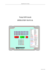
RVS-22HA
User’s Guide
Read this guide carefully before using the controller.
PRECAUTIONS
We strongly recommend connecting the controller to an alarm system, and installing
a supplementary natural ventilation system as well as a back-up thermostat on at
least one cooling stage. Refer to the wiring diagram enclosed with this user’s guide
to connect the thermostat.
Input and output circuitry is protected against overload or overvoltage. However, we
recommend installing an additional protection device on the supply circuit as well as
an external relay on all ON-OFF stages to prolong the life of the controller.
To avoid exposing the controller to harmful gases or excessive humidity, it is
preferable to install it in a corridor.
The room temperature where the controller is located MUST ALWAYS REMAIN
BETWEEN 32° AND 104°F (0° AND 40°C).
DO NOT SPRAY WATER ON THE CONTROLLER.
FOR CUSTOMER USE
Enter below the serial number located
on the side of the controller and retain
this information for future reference.
Model number: RVS-22HA
Serial number:
________________
TABLE OF CONTENTS
GLOSSARY ................................................................................................................................ 2
VENTILATION SYSTEM OVERVIEW......................................................................................... 5
PARAMETER DESCRIPTION .................................................................................................... 6
LOCKED PARAMETERS ...................................................................................................... 6
ROOM TEMPERATURE MINIMUM/MAXIMUM..................................................................... 6
SET POINT/TEMPERATURE CURVE................................................................................... 7
CURRENT RAMPING DAY ................................................................................................... 9
MINIMUM SPEED/CURVE (STAGE 1).................................................................................. 9
BANDWIDTH/TIMER (STAGE 1)......................................................................................... 10
HUMIDITY MINIMUM/MAXIMUM (STAGE 1) ...................................................................... 11
RELATIVE HUMIDITY COMPENSATION (STAGE 1) ......................................................... 12
OFFSET/BANDWIDTH (STAGE 2)...................................................................................... 13
MINIMUM SPEED (STAGE 2) ............................................................................................. 13
DIFFERENTIAL (STAGE 4)................................................................................................. 14
DIFFERENTIAL (STAGE 3)................................................................................................. 15
TIMER (MIST) ..................................................................................................................... 16
OFFSET/DIFFERENTIAL (MIST) ........................................................................................ 17
OFFSET/DIFFERENTIAL (HEAT 2)..................................................................................... 17
OFFSET/DIFFERENTIAL (HEAT 1)..................................................................................... 18
ALARM OFFSETS............................................................................................................... 19
DIP SWITCHES AND PROBES ................................................................................................ 25
MOTOR TYPES ........................................................................................................................ 26
TECHNICAL SPECIFICATIONS ............................................................................................... 27
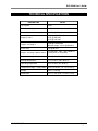
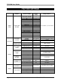
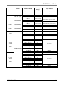
FACTORY SETTINGS .............................................................................................................. 28
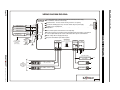
WIRING DIAGRAM ................................................................................................................... 30
NOTES...................................................................................................................................... 31
RAYDOT Ventilation Control
Page 1
GLOSSARY
or Located to the left of a parameter name, these arrows indicate that the user must either scroll up
or down to access the parameter, by pressing push-button A (scroll up) or B (scroll down) found
in the rightmost section of the faceplate.
A or B
Located to the left of a parameter name, the circled letters A or B indicate that the user accesses
the parameter directly, by pressing push-button A or B found in the rightmost section of the
faceplate.
Bandwidth
The bandwidth is the temperature interval within which the variable speed fans of a given stage
increase or decrease in speed proportionally to the temperature.
Cascading heaters
Heaters operate in a sequence. As the average room temperature drops, additional heaters are
turned on as needed.
Default value
A typical parameter setting defined at the factory.
Differential
The differential is the temperature difference between the moment the constant-speed fans or
heating units of a given stage start running and the moment they return to a stop.
Hysteresis
A hysteresis is used to smooth the transition from one state to another. For example, when the
temperature drops to the cut-off point for a stage of constant-speed fans, the fans will actually
cut off at slightly less than the cut-off point. This way, if the temperature fluctuates around the
cut-off point without dropping significantly below it, the controller will not oscillate between two
states. For example, if the hysteresis is 0.3°F and the stage 2 fans are programmed to cut off at
75.0°F, the cut-off will actually occur at 74.7°F.
Page 2
RAYDOT Ventilation Control
RVS-22HA User’s Guide
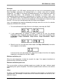
Messages
Messages appear in the LED display alternating with the value of the corresponding setting.
Some parameter adjustments are displayed both as a relative value and an absolute
temperature. This applies to all heating and cooling differentials, the mist differential and to the
heater and alarm offsets. The parameter is first displayed as a relative value. The
corresponding absolute temperature is displayed after 10 seconds if no action is taken by the
user. The absolute value is the temperature at which the stage turns on (except in the case of
the heater and mist offsets, where the value displayed is the temperature at which the stage
turns off). If the user turns the adjustment knob, the relative value reappears.
Here is an example of the sequence followed by the display when the user turns the selection
knob to the “STAGE 3 DIFF.” position.
1. The current differential for stage 3 flashes on the display, alternating with “St 3”.
2. If, after approximately 10 seconds, no action is taken by the user, the absolute
temperature value is displayed, alternating with “St 3”. In this case, the absolute value
is: Set Point + Stage 1 Bandwidth + Stage 2 Offset + Stage 2 Bandwidth + Stage 3
Differential.
3. When the user turns the adjustment knob to adjust the Stage 3 Differential, the relative
value reappears on the display.
In the case of the mist and heating units, when the user adjusts the offset, the stopping
temperature is displayed with the letters “StOP”.
Minimum ventilation cycle
When the room temperature is below the set point, the stage 1 fans operate intermittently to
provide minimum ventilation to the room.
Minimum ventilation speed curve
The user can define a minimum ventilation speed curve to adjust the stage 1 minimum speed
automatically over a given time period. The minimum speed increases over time as the animals
grow.
Offset
An offset is a temperature difference from the set point that normally defines a cut-off point for a
stage operation. For example, a heater offset of 2.0°F means the heaters will turn off at 2.0°F
above the set point.
RAYDOT Ventilation Control
Page 3
RVS-22HA User’s Guide
Set point
The set point is the target room temperature. When the temperature is above the set point, the
controller cools the room by turning on the cooling fans. When the temperature is below the set
point, the controller heats the room by turning on the heaters.
Temperature curve
The controller can be set to automatically change the temperature set point over a given period
of time in accordance with the user’s requirements. The set point decreases over time as the
animals grow.
Zoned heaters
When zoned heaters are used, heaters in each zone operate according to their corresponding
probes rather than from the average temperature of the entire room. This way, heaters operate
independently from one zone to the other. See page 25 “DIP SWITCHES AND PROBES” for
more information on zone temperatures.
Page 4
RAYDOT Ventilation Control
RVS-22HA User’s Guide
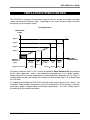
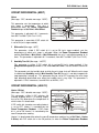
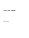
VENTILATION SYSTEM OVERVIEW
The RVS-22HA is a powerful environmental controller that can manage two variable ventilation
stages and two on/off ventilation stages. Depending on user setup, the on/off stages can either
be heating, mist or ventilation stages.
Cooling Operation
VENTILATION
LEVEL
Stage 4
Stage 3
Stage 2
Stage 1
Minimum
Ventilation
Cycle
Temperature Set Point
ROOM
TEMPERATURE
Stage 1
Bandwidth
Stage 1
Stage
2
Offset
Stage 2
Bandwidth
Stage 2
Stage 3
Diff.
Stage 4
Diff.
Stage 3
Stage 4
All outputs (except for alarms if “ind” is chosen at parameter Alarm Individual/All) are controlled
by the “room temperature”, which is the temperature averaged from # 1 to 4 probe readings.
Heaters follow either the room temperature or a zone temperature, depending on user setup. A
humidity probe may be used to lower the humidity level by activating stage 1 or by deactivating
the mist stage.
It is important to read both the RVS-22HA Installation Guide and the present User’s Guide. The
Installation Guide provides information on physical characteristics of the controller, mounting,
connections, probes, troubleshooting and technical specifications. The User’s Guide explains
the workings of the controller parameters.
RAYDOT Ventilation Control
Page 5
RVS-22HA User’s Guide
PARAMETER DESCRIPTION
LOCKED PARAMETERS
By setting DIP switch # 1 to the ON position, all parameters, except the Main Set Point and
Stage 1 Minimum Speed, are “locked” to prevent modifications. After the user has set
parameters to the desired values, he may want to lock these values for safety.
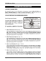
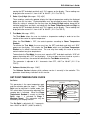
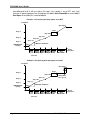
ROOM TEMPERATURE MINIMUM/MAXIMUM
The actual room temperature, averaged from
activated interior probe readings, controls all
outputs (except the heaters if zoned) and
alarms (except if “ind” is chosen at parameter
Alarm Individual/All).
ALARM OFFSETS
HEAT 1
HEAT 2
MIST
MAX
SET POINT / T°CURVE
OFFSET / DIFF.
CURRENT RAMPING DAY
OFFSET / DIFF.
MIN. SPEED / CURVE
OFFSET / DIFF.
BANDWIDTH / TIMER
STAGE 1
HUMIDITY MIN / MAX
(SEC.)
TIMER ON
OFF (MIN.)
STAGE 3
This parameter is displayed to the nearest
0.1°, from -6.0°F to 168.6°F (-21.1°C to 75.9°C).
ROOM TEMP.
MIN
Room Temperature Readout
DIFF.
DIFF.
STAGE 4
RH COMPENSATION
OFFSET / BANDWIDTH
MIN. SPEED
STAGE 2
Room Temperature Low (Message: “Lo”)
Continually updated, this reading shows the lowest room temperature reached since the last
clear. While this setting is selected, the user may clear the Room Temperature Low and
High values, along with all individual probe lows and highs, by moving the SET knob back
and forth until “CLr” appears on the display. This reading is displayed to the nearest 0.1°,
from -6.0°F to 168.6°F (-21.1°C to 75.9°C).
Room Temperature High (Message: “Hi”)
Continually updated, this reading shows the highest room temperature reached since the last
clear. While this setting is selected, the user may clear the Room Temperature High and
Low values, along with all individual probe lows and highs, by moving the SET knob back
and forth until “CLr” appears on the display. This reading is displayed to the nearest 0.1°,
from -6.0°F to 168.6°F (-21.1°C to 75.9°C).
Probe 1 (to 4) Readout (Messages: “Pr[1-4]”)
These settings display the actual temperature read by the displayed probe if that probe is
activated (see the DIP switch table). These temperatures are used to calculate the Room
Temperature Readout as well as the A and B temperature zones, used for the heaters.
These readings are displayed to the nearest 0.1°, from -6.0°F to 168.6°F (-21.1°C to 75.9°C).
Probe 1 (to 4) Low (Messages: “Pr[1-4]Lo”)
These readings, continually updated, display the lowest temperature read by the displayed
probe since the last clear. Displayed probes must be activated to access these readings.
While this setting is selected, the user may clear the Probe [#] Low reading, along with all
individual probe lows and highs, and along with the Room Temperature Low and High, by
Page 6
RAYDOT Ventilation Control
RVS-22HA User’s Guide
moving the SET knob back and forth until “CLr” appears on the display. These readings are
displayed to the nearest 0.1°, from -6.0°F to 168.6°F (-21.1°C to 75.9°C).
Probe 1 (to 4) High (Messages: “Pr[1-4]Hi”)
These readings, continually updated, display the highest temperature read by the displayed
probe since the last clear. Displayed probes must be activated to access these readings.
While this setting is selected, the user may clear the Probe [#] High reading, along with all
individual probe lows and highs, and along with the Room Temperature Low and High, by
moving the SET knob back and forth until “CLr” appears on the display. These readings are
displayed to the nearest 0.1°, from -6.0°F to 168.6°F (-21.1°C to 75.9°C).
Test Mode (Message: “tESt”)
The Test Mode allows the user to simulate a temperature reading in order to test the
reaction of the control at a given temperature.
When the Test Mode is OFF, the control operates according to Room Temperature
Readout.
To activate the Test Mode, the user must turn the SET knob back and forth until “tESt”
appears on the display. This unlocks the Test Mode, which uses the Room Temperature
Readout as its default simulated value. The user may then modify this value to test the
control reaction to a given temperature.
To deactivate the Test Mode, the user must move the SET knob back and forth; “tESt” will
appear alternating with “OFF” on the display. If the user does not turn a knob or a push a
button for five minutes, the control will deactivate the Test Mode automatically.
This parameter is adjusted in 0.1° increments from OFF, -6.0°F to 168.6°F (-21.1°C to
75.9°C).
Software Version (Message: “SoFt”)
The Software Version indicates which software version is currently in the controller. This
parameter should always indicate 2 for this version.
SET POINT/TEMPERATURE CURVE
Set Point
ROOM TEMP.
MIN
This parameter is the room temperature goal
and the activation point for stage 1. The Set
Point can be adjusted in locked mode (see
DIP switch table), but cannot be adjusted if the
ramping day is activated. When the Room
Temperature Readout is exactly at the Set
Point, stage 1 is activated at Stage 1
Minimum Speed. This parameter may be
affected by the ramping function.
ALARM OFFSETS
HEAT 1
HEAT 2
MIST
MAX
SET POINT / T°CURVE
OFFSET / DIFF.
CURRENT RAMPING DAY
OFFSET / DIFF.
MIN. SPEED / CURVE
OFFSET / DIFF.
BANDWIDTH / TIMER
STAGE 1
HUMIDITY MIN / MAX
(SEC.)
TIMER ON
OFF (MIN.)
STAGE 3
DIFF.
DIFF.
STAGE 4
RH COMPENSATION
OFFSET / BANDWIDTH
MIN. SPEED
STAGE 2
The Set Point is adjusted in 0.1° increments,
from -40.0°F to 100.0°F (-40.0°C to 40.0°C).
RAYDOT Ventilation Control
Page 7
RVS-22HA User’s Guide
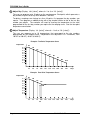
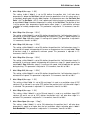
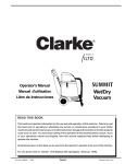
A Adjust Day (Display: “d#: [value]”, where # = 1 to 9, or “10: [value]”)
The user can program up to 10 points on the ramping curve. Each point, which represents a
day number, may be set to any value between 1 and 255.
To obtain a ramping curve having less than 10 points, first program the day numbers you
require. Then program an additional day with a day number inferior to that of the last day
number you require. The controller will react by leveling the temperature to the value
programmed for the last day number you require on the ramping curve. See the four-point
temperature curve below.
B Adjust Temperature (Display: “t#: [value]”, where # = 1 to 9, or “10: [value]”)
The user can program up to 10 temperatures that correspond to the day numbers
programmed on the ramping curve. Temperatures are adjusted in 0.1° increments, from
-40.0°F to 100.0°F (-40.0°C to 40.0°C).
Example: Ten-Point Temperature Curve
Temperature
°T 1
°T 2
°T 3
°T 4
°T 5
°T 6
°T 7
°T 8
°T 9
°T 10
D1
D2
D3
D4
D5
D6
D7
D8
D9
D10
25
50
75
100
125
150
175
200
225
255
Days
225
255
Days
Example: Four-Point Temperature Curve
Temperature
°T 1
°T 2
°T 3
°T 4
°T 5
°T 6
°T 7
°T 8
°T 9
°T 10
D1
D2
D3
D4
D5
25
Page 8
50
75
100
90
125
150
175
200
RAYDOT Ventilation Control
RVS-22HA User’s Guide
CURRENT RAMPING DAY
ROOM TEMP.
MIN
Current Day
All active ramping parameters will be based on
the day number displayed by this setting.
SET POINT / T°CURVE
ALARM OFFSETS
HEAT 1
HEAT 2
MIST
OFFSET / DIFF.
CURRENT RAMPING DAY
OFFSET / DIFF.
MIN. SPEED / CURVE
OFFSET / DIFF.
BANDWIDTH / TIMER
STAGE 1
HUMIDITY MIN / MAX
ON (SEC.)
The Current Day can be OFF or be set to any
value from 1 to 255.
MAX
TIMER OFF (MIN.)
STAGE 3
DIFF.
RH COMPENSATION
OFFSET / BANDWIDTH
DIFF.
MIN. SPEED
STAGE 4
STAGE 2
A Adjust Current Day
The Current Day can be turned OFF, deactivating all ramping curve functions, or adjusted to
any day number from 1 to 255.
MINIMUM SPEED/CURVE (STAGE 1)
Minimum Speed
Stage 1 can never be activated at a speed
lower than Stage 1 Minimum Speed. This
parameter, one of only two adjustable
parameters in locked mode, may be affected
by the ramping function.
HEAT 2
MIST
MAX
SET POINT / T°CURVE
ALARM OFFSETS
HEAT 1
OFFSET / DIFF.
CURRENT RAMPING DAY
OFFSET / DIFF.
MIN. SPEED / CURVE
OFFSET / DIFF.
BANDWIDTH / TIMER
STAGE 1
HUMIDITY MIN / MAX
(SEC.)
TIMER ON
OFF (MIN.)
STAGE 3
Stage 1 Minimum Speed is adjusted in 1%
increments from 12% to 100%.
ROOM TEMP.
MIN
DIFF.
RH COMPENSATION
DIFF.
STAGE 4
OFFSET / BANDWIDTH
MIN. SPEED
STAGE 2
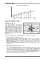
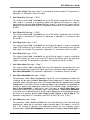
A Adjust Day (Display: “d#: [value]”, where # = 1 to 9, or “10: [value]”)
The user can program up to 10 points, each corresponding to a day, on the ramping curve.
To deactivate the ramping function for Stage 1 Minimum Speed, the user must set the first
point to OFF. Each day may be set at any value between 1 and 255.
B Adjust Minimum Speed (Display: “S#: [value]”, where # = 1 to 9, or “10: [value]”)
The user can program up to 10 minimum speeds that correspond to day numbers on the
ramping curve. These values are adjusted in 1% increments from 12% to 100%.
RAYDOT Ventilation Control
Page 9
RVS-22HA User’s Guide
Example: Minimum Speed Curve
Speed
D7
D1
25
D2
43
D3
63
D4
89
D9
D8
D10
D5 D6
113 130
162
184
221
Days
244
BANDWIDTH/TIMER (STAGE 1)
Bandwidth (Message: “bd”)
ROOM TEMP.
MIN
The stage 1 bandwidth is the temperature
range within which stage 1 accelerates from
Stage 1 Minimum Speed to its maximum
speed (100%). When the Room Temperature
Readout reaches the Set Point, stage 1
operates continuously at minimum speed. As
the Room Temperature Readout increases,
stage 1 speeds up until Set Point + Stage 1
Bandwidth is reached, at which point stage 1
operates at 100%.
ALARM OFFSETS
HEAT 1
HEAT 2
MIST
MAX
SET POINT / T°CURVE
OFFSET / DIFF.
CURRENT RAMPING DAY
OFFSET / DIFF.
MIN. SPEED / CURVE
OFFSET / DIFF.
BANDWIDTH / TIMER
STAGE 1
HUMIDITY MIN / MAX
(SEC.)
TIMER ON
OFF (MIN.)
STAGE 3
DIFF.
DIFF.
STAGE 4
RH COMPENSATION
OFFSET / BANDWIDTH
MIN. SPEED
STAGE 2
This parameter is adjusted in 0.1° increments, from 0.5°F to 20.0°F (0.3°C to 11.0°C).
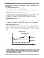
Minimum Ventilation On Time (Message: “On”)
This parameter adjusts the time during which the minimum ventilation timer is on. When the
Room Temperature Readout is below the Set Point, stage 1 is activated at Stage 1
Minimum Speed during the time specified for this parameter, and is deactivated for
Minimum Ventilation Off Time. To deactivate minimum ventilation, simply set this
parameter to 0. Minimum Ventilation On Time is adjusted in 15-second increments, from 0
to 900 seconds.
Minimum Ventilation Off Time (Message: “OFF”)
When the Room Temperature Readout is below the Set Point, the control is in minimum
ventilation. During minimum ventilation, stage 1 is activated at Stage 1 Minimum Speed
during Minimum Ventilation On Time and deactivated during the time specified for this
parameter. To have stage 1 operate continuously at Stage 1 Minimum Speed when in
minimum ventilation, simply adjust this parameter to 0. Minimum Ventilation Off Time is
adjusted in 15-second increments, from 0 to 900 seconds.
Page 10
RAYDOT Ventilation Control
RVS-22HA User’s Guide
Minimum Ventilation Cycle
Minimum Ventilation On Time
Stage 1 minimum speed
OFF
Minimum Ventilation Off Time
Motor Type (Message: “tyP”)
This parameter allows the user to choose the motor type for stage 1. The right motor type
ensures correct supply voltage at a given speed. Refer to the motor type table for the list of
available motor types.
HUMIDITY MINIMUM/MAXIMUM (STAGE 1)
Readout (Message: “rH”)
ROOM TEMP.
MIN
This parameter displays the actual relative
humidity. Humidity can affect stage 1 and
mist stage behaviors.
The humidity probe is optional. When there is
no humidity probe, dehumidification and mist
shut off logics are deactivated. To learn more
about deactivating the humidity logic, read the
Compensation Option parameter description
below.
SET POINT / T°CURVE
ALARM OFFSETS
HEAT 1
HEAT 2
MIST
MAX
OFFSET / DIFF.
CURRENT RAMPING DAY
OFFSET / DIFF.
MIN. SPEED / CURVE
OFFSET / DIFF.
BANDWIDTH / TIMER
STAGE 1
HUMIDITY MIN / MAX
(SEC.)
TIMER ON
OFF (MIN.)
STAGE 3
DIFF.
RH COMPENSATION
DIFF.
STAGE 4
OFFSET / BANDWIDTH
MIN. SPEED
STAGE 2
This parameter is displayed to the nearest 1 RH% from 10 RH% to 90 RH%.
Humidity Low (Message: “rH Lo”)
Continually updated, this reading shows the lowest humidity read by the probe since the last
clear. While this setting is selected, the user may clear the Humidity Low and High values
by moving the SET knob back and forth until “CLr” appears on the display. This reading is
displayed in 1 RH% increments, from 10 RH% to 90 RH%.
Humidity High (Message: “rH Hi”)
Continually updated, this reading shows the highest humidity read by the probe since the last
clear. While this setting is selected, the user may clear the Humidity Low and High values
by moving the SET knob back and forth until “CLr” appears on the display. This reading is
displayed in 1 RH% increments, from 10 RH% to 90 RH%.
RAYDOT Ventilation Control
Page 11
RVS-22HA User’s Guide
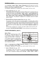
RELATIVE HUMIDITY COMPENSATION (STAGE 1)
Compensation Option (Message: “OPt”)
ROOM TEMP.
MIN
This parameter activates or deactivates all
humidity logic. Setting this parameter to OFF
eliminates the Relative Humidity Speed
Compensation logic as well as the Humidity
Turn Off mist logic. This parameter can be set
to OFF or ON.
SET POINT / T°CURVE
ALARM OFFSETS
HEAT 1
HEAT 2
MIST
MAX
OFFSET / DIFF.
CURRENT RAMPING DAY
OFFSET / DIFF.
MIN. SPEED / CURVE
OFFSET / DIFF.
BANDWIDTH / TIMER
STAGE 1
HUMIDITY MIN / MAX
ON (SEC.)
TIMER OFF (MIN.)
STAGE 3
DIFF.
For more details on humidity logic, read the
Relative Humidity Speed Compensation
parameter description below.
STAGE 4
Ex.: Compensation Option =
Stage 1 Minimum Speed =
Humidity Set Point =
Relative Humidity Speed Compensation =
ON
20%
70 RH%
50%
RH COMPENSATION
OFFSET / BANDWIDTH
DIFF.
MIN. SPEED
STAGE 2
Humidity Speed Compensation
Stage 1 Compensated
Minimum Speed (%)
100
Compensation begins
80
60
RH Speed
Compensation
40
20
10 RH%
Humid
0
Normal
Minimum
Speed
30
40
50
60
70
80
90
y (RH%)
Relative Humidity Set Point
Humidity Set Point (Message: “rH SP”)
This parameter, visible if the Compensation Option parameter is set to ON, represents the
humidity level to reach before dehumidification can start. If stage 1 is not activated and
Humidity reaches Humidity Set Point, stage 1 operates at Stage 1 Minimum Speed
regardless of the minimum ventilation timer. Stage 1 accelerates as Humidity increases, to
reach Stage 1 Minimum Speed + Relative Humidity Speed Compensation when
Humidity reaches Humidity Set Point + 10 RH%. If stage 1 is already activated, its
minimum speed will be adjusted in the same manner. Stage 1 modulates from the
compensated minimum speed to 100% according to the Room Temperature Readout. This
parameter is adjusted in 1 RH% increments, from 10 RH% to 90 RH%. The previous
parameter description provides an example.
Page 12
RAYDOT Ventilation Control
RVS-22HA User’s Guide
Relative Humidity Speed Compensation (Message: “SPd”)
This parameter, visible if the Compensation Option parameter is set to ON, is used to
adjust stage 1’s speed compensation for dehumidification. Stage 1’s speed will increase by
this amount when Humidity reaches Humidity Set Point + 10 RH%. Setting this parameter
to 0% does not affect stage 1’s speed when it is already activated by temperature demand,
but activates stage 1 continuously at Stage 1 Minimum Speed when the Room
Temperature Readout is below the Set Point and Humidity is at or above Humidity Set
Point. This parameter is adjusted in 1% increments, from 0% to 100%.
OFFSET/BANDWIDTH (STAGE 2)
Offset
(Message: “OFt”; absolute message: “St 2”)
ROOM TEMP.
MIN
MAX
SET POINT / T°CURVE
ALARM OFFSETS
This parameter sets the offset for stage 2. The
HEAT 1
OFFSET / DIFF.
CURRENT RAMPING DAY
offset for stage 2 is the difference between the
HEAT 2
OFFSET / DIFF.
MIN. SPEED / CURVE
end of stage 1’s modulation band and the
MIST OFFSET / DIFF.
BANDWIDTH / TIMER
activation point for stage 2. When the Room
STAGE 1
(SEC.)
TIMER ON
HUMIDITY MIN / MAX
OFF (MIN.)
Temperature Readout reaches Set Point +
STAGE 3
DIFF.
RH COMPENSATION
Stage 1 Bandwidth + Stage 2 Offset, stage 2
DIFF.
OFFSET / BANDWIDTH
is activated at Stage 2 Minimum Speed.
MIN. SPEED
STAGE 4
STAGE 2
Stage 2 will be deactivated when the Room
Temperature Readout drops to Set Point +
Stage 1 Bandwidth + Stage 2 Offset – 0.3°F (0.2°C). This parameter is adjusted in 0.1°
increments, from 0.5°F to 20.0°F (0.3°C to 11.0°C).
Bandwidth (Message: “bd”)
This bandwidth is the temperature range within which stage 2 accelerates from Stage 2
Minimum Speed to its maximum speed (100%). When the Room Temperature Readout
reaches the Set Point + Stage 1 Bandwidth + Stage 2 Offset, stage 2 operates
continuously at minimum speed. As the Room Temperature Readout increases, stage 2
speeds up until Set Point + Stage 1 Bandwidth + Stage 2 Offset + Stage 2 Bandwidth is
reached. At this point, stage 2 operates at 100%. This parameter is adjusted in 0.1°
increments, from 0.5°F to 20.0°F (0.3°C to 11.0°C).
MINIMUM SPEED (STAGE 2)
ROOM TEMP.
MIN
Minimum Speed
(Message: “SPd”)
ALARM OFFSETS
HEAT 1
HEAT 2
Stage 2 will never operate at a speed lower
than this speed, its minimum speed.
MIST
CURRENT RAMPING DAY
OFFSET / DIFF.
MIN. SPEED / CURVE
OFFSET / DIFF.
BANDWIDTH / TIMER
STAGE 1
HUMIDITY MIN / MAX
STAGE 3
DIFF.
DIFF.
STAGE 4
RAYDOT Ventilation Control
SET POINT / T°CURVE
OFFSET / DIFF.
(SEC.)
TIMER ON
OFF (MIN.)
Stage 2 Minimum Speed is adjusted in 1%
increments, from 12% to 100%.
MAX
RH COMPENSATION
OFFSET / BANDWIDTH
MIN. SPEED
STAGE 2
Page 13
RVS-22HA User’s Guide
De-Icing Cycle Time (Message: “Cyc”)
This parameter, visible if DIP switch # 11 (de-icing option) is set to ON, establishes the
length of time during which stage 2 de-icing is inactive. If stage 2 stays deactivated for a
longer period of time than De-Icing Cycle Time, stage 2 is activated at minimum speed for
De-Icing On Time. This parameter is adjusted in 1-minute increments, from 1 to 720
minutes.
De-Icing On Time (Message: “On”)
This parameter, visible if DIP switch # 11 (de-icing option) is set to ON, establishes the
length of time during which stage 2 de-icing is active. During de-icing, stage 1 becomes
deactivated during the time specified in the present parameter. If stage 2 stays deactivated
for more than De-Icing Cycle Time, stage 2 is activated at minimum speed for De-Icing On
Time. This parameter is adjusted in 1-second increments, from 0 to 900 seconds.
Motor Type (Message: “tyP”)
This parameter allows the user to choose the motor type for stage 2. The right motor type
ensures correct supply voltage at a given speed. Refer to the motor type table for the list of
available motor types.
DIFFERENTIAL (STAGE 4)
Stage 4 Differential
(Message: “St 4”; absolute message: “St 4”)
This parameter, invisible if DIP switches # 6 or
# 9 are set to ON, adjusts the temperature at
which stage 4 is activated.
ALARM OFFSETS
HEAT 1
HEAT 2
MIST
When the Room Temperature Readout
reaches Set Point + Stage 1 Bandwidth +
Stage 2 Offset + Stage 2 Bandwidth + Stage
3 Differential + Stage 4 Differential, stage 4
is activated.
ROOM TEMP.
MIN
MAX
SET POINT / T°CURVE
OFFSET / DIFF.
CURRENT RAMPING DAY
OFFSET / DIFF.
MIN. SPEED / CURVE
OFFSET / DIFF.
BANDWIDTH / TIMER
STAGE 1
HUMIDITY MIN / MAX
(SEC.)
TIMER ON
OFF (MIN.)
STAGE 3
DIFF.
DIFF.
STAGE 4
RH COMPENSATION
OFFSET / BANDWIDTH
MIN. SPEED
STAGE 2
This parameter is adjusted in 0.1° increments, from 0.5°F to 20.0°F (0.3°C to 11.0°C).
Page 14
RAYDOT Ventilation Control
RVS-22HA User’s Guide
DIFFERENTIAL (STAGE 3)
Stage 3 Differential
(Message: “St 3”; absolute message: “St 3”)
This parameter is invisible if DIP switches # 6
and 9, or # 6 and 7, are set to ON. This setting
adjusts the temperature at which stage 3 is
activated.
ROOM TEMP.
MIN
ALARM OFFSETS
HEAT 1
HEAT 2
MIST
SET POINT / T°CURVE
OFFSET / DIFF.
CURRENT RAMPING DAY
OFFSET / DIFF.
MIN. SPEED / CURVE
OFFSET / DIFF.
BANDWIDTH / TIMER
STAGE 1
HUMIDITY MIN / MAX
ON (SEC.)
When the Room Temperature Readout
reaches Set Point + Stage 1 Bandwidth +
Stage 2 Offset + Stage 2 Bandwidth + Stage
3 Differential, stage 3 is activated.
MAX
TIMER OFF (MIN.)
STAGE 3
DIFF.
DIFF.
RH COMPENSATION
OFFSET / BANDWIDTH
MIN. SPEED
STAGE 4
STAGE 2
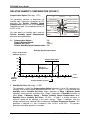
This parameter is adjusted in 0.1° increments, from 0.5°F to 20.0°F (0.3°C to 11.0°C).
Using a Fixed Offset on on/off Stages*
ON/OFF
VENTILATION
STAGES
Stage 4: ON
Stage 3: ON
OFF
Offset
2.0°F (1.1°C)
Stage 3
Differential
Offset
2.0°F (1.1°C)
ROOM
TEMPERATURE
Stage 4
Differential
* This example, with DIP switch # 10 in the ON position, applies not only to stages 3 and 4, but also to all on/off
ventilation stages. If DIP switch # 10 is in the OFF position, the logic that applies is illustrated by the diagram found
in the Ventilation System Overview section.
RAYDOT Ventilation Control
Page 15
RVS-22HA User’s Guide
TIMER (MIST)
Mist On Time (Message: “On”)
ROOM TEMP.
MIN
This parameter, accessible if DIP switch # 9 is
set to ON (mist stage enabled), adjusts the
mist timer ON time. Refer to the DIP switch
table in the last pages of this document.
This parameter adjusts the mist timer ON time.
When the temperature is above Set Point +
Mist Offset + Mist Differential, the mist is
activated on a timer. The mist is activated
during this period of time and then deactivated
for Mist Off Time.
ALARM OFFSETS
HEAT 1
HEAT 2
MIST
MAX
SET POINT / T°CURVE
OFFSET / DIFF.
CURRENT RAMPING DAY
OFFSET / DIFF.
MIN. SPEED / CURVE
OFFSET / DIFF.
BANDWIDTH / TIMER
STAGE 1
HUMIDITY MIN / MAX
ON (SEC.)
TIMER OFF (MIN.)
STAGE 3
DIFF.
DIFF.
RH COMPENSATION
OFFSET / BANDWIDTH
MIN. SPEED
STAGE 4
STAGE 2
To deactivate the mist stage, simply adjust the setting to 0. Mist On Time is adjusted in 15second increments, from 0 to 900 seconds.
Mist Off Time (Message: “OFF”)
This parameter, visible if DIP switch # 9 is set to ON (mist stage enabled), adjusts the mist
timer OFF time. When the temperature is above Set Point + Mist Offset + Mist Differential,
the mist is activated on a timer. If Mist Off Time is set to 0, the mist output is not affected by
Humidity and runs continuously like a fan. The mist is deactivated during this period of time
and then activated for Mist On Time. Mist Off Time is adjusted in 1-minute increments,
from 0 to 20 minutes.
Mist Cooling
Mist stage turns on
in timer mode
Mist stage turns off
Mist
OFF
Mist
Offset
Mist
Diff.
Room
Temperature
Set Point
Mist Timer Cycle
On Time
ON
OFF
Off Time
Page 16
RAYDOT Ventilation Control
RVS-22HA User’s Guide
OFFSET/DIFFERENTIAL (MIST)
Offset
(Message: “OFt”; absolute message: “StOP”)
ROOM TEMP.
MIN
SET POINT / T°CURVE
ALARM OFFSETS
This parameter sets the temperature at which
mist stage is deactivated.
The mist is
deactivated when the Room Temperature
Readout drops to Set Point + Mist Offset.
HEAT 1
HEAT 2
MIST
OFFSET / DIFF.
CURRENT RAMPING DAY
OFFSET / DIFF.
MIN. SPEED / CURVE
OFFSET / DIFF.
BANDWIDTH / TIMER
STAGE 1
HUMIDITY MIN / MAX
ON (SEC.)
TIMER OFF (MIN.)
This parameter is adjusted in 0.1° increments,
from 0.5°F to 20.0°F (0.3°C to 11.0°C).
MAX
STAGE 3
DIFF.
RH COMPENSATION
OFFSET / BANDWIDTH
DIFF.
MIN. SPEED
STAGE 4
STAGE 2
This parameter is accessible if DIP switch # 9
is set to ON (mist stage enabled).
Differential (Message: “diFF”)
This parameter, visible if DIP switch # 9 is set to ON (mist stage enabled), sets the
temperature at which mist stage is activated. When the Room Temperature Readout
reaches Set Point + Mist Offset + Mist Differential, the mist is activated according to its
timer. This parameter is adjusted in 0.1° increments, from 0.5°F to 20.0°F (0.3°C to 11.0°C).
Humidity Turn Off (Message: “rHOFF”)
This parameter is visible if DIP switch # 9 is set to ON (mist stage enabled), if the
Compensation Option parameter is ON, and if Mist Off Time is set to a different value than
0.
This parameter sets the humidity level at which the mist stage shuts off. When the mist stage
is enabled and Humidity reaches Mist Humidity Turn Off, the mist is not able to operate or
stops operating if already on. This parameter may be set to OFF to prevent the mist stage
from becoming deactivated even when the humidity level is very high. This parameter is
adjusted in 1 RH% increments, from 40 RH% to 90 RH%, OFF.
OFFSET/DIFFERENTIAL (HEAT 2)
Heater 2 Offset
(Message: “OFt”; absolute message: “StOP”)
This parameter, visible if DIP switches # 6
(heating enabled) and # 7 (2 heating stages)
are set to ON, determines the temperature at
which heater 2 is deactivated.
If DIP switch # 8 (zoned or cascading heaters)
is set to OFF, heater 2 is controlled by the
Room Temperature Readout. If DIP switch
# 8 is set to ON, heater 2 is controlled by the
zone B temperature reading.
ROOM TEMP.
MIN
ALARM OFFSETS
HEAT 1
HEAT 2
MIST
MAX
SET POINT / T°CURVE
OFFSET / DIFF.
CURRENT RAMPING DAY
OFFSET / DIFF.
MIN. SPEED / CURVE
OFFSET / DIFF.
BANDWIDTH / TIMER
STAGE 1
HUMIDITY MIN / MAX
(SEC.)
TIMER ON
OFF (MIN.)
STAGE 3
DIFF.
DIFF.
STAGE 4
RH COMPENSATION
OFFSET / BANDWIDTH
MIN. SPEED
STAGE 2
Heater 2 is deactivated either when the zone B temperature reading rises to Set Point – Heater
2 Offset, with DIP switch # 8 in the ON position, or when the Room Temperature Readout
RAYDOT Ventilation Control
Page 17
RVS-22HA User’s Guide
rises to Set Point – Heater 1 Offset – Heater 1 Differential, with DIP switch # 8 in the OFF
position. In the latter case, this parameter will display “-----“ indicating that this value is not used
to calculate the activation and deactivation points.
This parameter is adjusted in 0.1° increments, from -10.0°F to 20.0°F (-5.5°C to 11.0°C).
Heater 2 Differential (Message: “diFF”)
This parameter, visible if DIP switches # 6 (heating enabled) and # 7 (2 heating stages) are
set to ON, determines the activation point for heater 2. Heater 2 is activated when the zone
B temperature reading reaches Set Point – Heater 2 Offset – Heater 2 Differential with
DIP switch # 8 in the ON position, or when the Room Temperature Readout reaches Set
Point – Heater 1 Offset – Heater 1 Differential – Heater 2 Differential, with DIP switch # 8
in the OFF position. This parameter is adjusted in 0.1° increments, from 0.5°F to 20.0°F
(0.3°C to 11.0°C).
Maximum Difference Protection between Zones (Message: “dProt”)
This parameter, visible if DIP switches # 6 (heating enabled), # 7 (2 heating stages) and # 8
(zoned heating) are set to ON, defines the maximum difference allowed between zone A and
zone B for desired heater operation. When the difference between these two zones exceeds
this parameter, all cooling stages follow the highest zone temperature. Setting this
parameter to OFF means that cooling stages follow the Room Temperature Readout at all
times.
This parameter is adjusted in 0.1° increments, from 5.0°F to 40.0°F (3.0°C to 22.0°C), OFF.
See page 25 “DIP SWITCHES AND PROBES” for more information on zone temperatures.
OFFSET/DIFFERENTIAL (HEAT 1)
Heater 1 Offset
(Message: “OFt”; absolute message: “StOP”)
This parameter, visible if DIP switch # 6 is set
to ON (heating enabled), determines the
temperature at which heater 1 is deactivated.
ALARM OFFSETS
HEAT 1
HEAT 2
MIST
If DIP switch # 8 (zoned or cascading heaters)
is set to OFF, heater 1 is controlled by the
Room Temperature Readout. If DIP switch
# 8 is set to ON, heater 1 is controlled by the
zone A temperature reading.
ROOM TEMP.
MIN
MAX
SET POINT / T°CURVE
OFFSET / DIFF.
CURRENT RAMPING DAY
OFFSET / DIFF.
MIN. SPEED / CURVE
OFFSET / DIFF.
BANDWIDTH / TIMER
STAGE 1
HUMIDITY MIN / MAX
ON (SEC.)
TIMER OFF (MIN.)
STAGE 3
DIFF.
DIFF.
STAGE 4
RH COMPENSATION
OFFSET / BANDWIDTH
MIN. SPEED
STAGE 2
Heater 1 is deactivated when the Room Temperature Readout or the zone A temperature
reading rises to Set Point – Heater 1 Offset.
This parameter is adjusted in 0.1° increments, from -10.0°F to 20.0°F (-5.5°C to 11.0°C).
Heater 1 Differential (Message: “diFF”)
This parameter, visible if DIP switch # 6 is set to ON (heating enabled), determines the
activation point for heater 1. Heater 1 is activated when the Room Temperature Readout
or the zone A temperature reading reaches Set Point – Heater 1 Offset – Heater 1
Page 18
RAYDOT Ventilation Control
RVS-22HA User’s Guide
Differential. This parameter is adjusted in 0.1° increments, from 0.5°F to 20.0°F (0.3°C to
11.0°C).
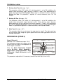
Zoned Heater Operation
`
HEATING
Heater
turns on
Heater
turns off
ON
OFF
Heater
Differential
ZONE
TEMPERATURE
Heater
Offset
Set Point
Cascading Heaters Operation
Heater 2 ON
Heater 2
Heater 2 OFF
Heater 1 ON
Heater 1 OFF
Heater 1
OFF
Heater 2
Differential
Heater 1
Differential
Heater 1
Offset
ROOM
TEMPERATURE
Set Point
ALARM OFFSETS
Low Alarm Offset
(Message: “Lo”; absolute message: “Lo”)
ROOM TEMP.
MIN
SET POINT / T°CURVE
ALARM OFFSETS
This parameter determines the temperature at
which occurs a low alarm condition.
HEAT 1
HEAT 2
MIST
When the temperature* is lower than Set Point
– Low Alarm Offset, the alarm sets off.
This parameter is adjusted in 0.1° increments,
from 0.5°F to 40.0°F (0.3°C to 20.0°C).
MAX
OFFSET / DIFF.
CURRENT RAMPING DAY
OFFSET / DIFF.
MIN. SPEED / CURVE
OFFSET / DIFF.
BANDWIDTH / TIMER
STAGE 1
HUMIDITY MIN / MAX
(SEC.)
TIMER ON
OFF (MIN.)
STAGE 3
DIFF.
RH COMPENSATION
DIFF.
STAGE 4
OFFSET / BANDWIDTH
MIN. SPEED
STAGE 2
* Refer to the Alarm Individual/All parameter for more details on the monitored temperature.
RAYDOT Ventilation Control
Page 19
RVS-22HA User’s Guide
The alarm is normally activated, but will be deactivated 13 seconds or more after one of the
following events:
1. The RVS-22HA loses its power;
2. The temperature* is lower than Low Alarm Offset;
3. The temperature* is higher than High Alarm Offset;
4. The temperature* is higher than the Critical High Alarm parameter;
5. An active temperature probe is defective (disconnected, open circuit, short-circuit).
High Alarm Offset (Message: “Hi”; absolute message: “Hi”)
This parameter determines the temperature at which occurs a high alarm condition. When
the temperature* is higher than Set Point + High Alarm Offset, the alarm sets off.
This parameter is adjusted in 0.1° increments, from 0.5°F to 40.0°F (0.3°C to 22.0°C).
Critical High Alarm (Message: “Cri”)
This parameter determines the temperature at which occurs a critical high alarm condition.
When the temperature* is higher than Critical High Alarm, the alarm sets off.
This parameter is adjusted in 0.1° increments, from -40.0°F to 120.0°F (-40.0°C to 50.0°C).
Alarm Individual/All (Message: “AL”)
This parameter allows the user to choose the temperature alarm condition. If set to “ALL”, a
temperature alarm will only set off when the average reading of all probes (the value
displayed in the Room Temperature Readout parameter) is out of the alarm offset range. If
set to “ind”, the alarm sets off as soon as any individual probe is out of the alarm offset
range.
Operation of Alarm
Room
Temperature
High Temperature Alarm
High Alarm Offset
Set Point Low Alarm Offset
Time
Inlet 1 (Message: “In 1”)
This setting allows the user to activate or deactivate Inlet 1. If this parameter is set to ON, all
inlet 1 settings and the Inlet 2 option will become visible and inlet 1 will position itself
according to stage activation or temperature. If set to OFF, those settings will not appear and
inlet 1 will receive a constant close signal.
Page 20
RAYDOT Ventilation Control
RVS-22HA User’s Guide
Inlet 1 Step 0 (Message: “1 S0”)
This setting, visible if Inlet 1 is set to ON, defines the position inlet 1 will take when
temperature is below the Set Point. Inlet will never be opened less than this value unless it
is completely deactivated using the Inlet 1 option. As temperature nears the Set Point (Set
Point – 0.4°F or Set Point – 0.2°C), inlet’s opening will start to increase as temperature rises
to reach Inlet 1 Step 1 Lo when temperature is exactly at the Set Point. The position of inlet
1 will be greater than temperature would require when stage 1 is activated for minimum
ventilation or humidity compensation. This parameter is adjusted in 1% increments, from 0%
to 100%.
Inlet 1 Step 1 Lo (Message: “1 S1L”)
This setting, visible if Inlet 1 is set to ON, defines the position inlet 1 will take when stage 1 is
activated at its minimum speed. Inlet opening will increase as stage 1’s speed increases to
reach Inlet 1 Step 1 Hi when stage 1 is running at full speed. This parameter is adjusted in
1% increments, from 0% to 100%.
Inlet 1 Step 1 Hi (Message: “1 S1H”)
This setting, visible if Inlet 1 is set to ON, defines the position inlet 1 will take when stage 1 is
activated at full speed. Inlet opening will increase as temperature rises to reach Inlet 1 Step
2 Lo when stage 2 is activated at minimum speed. This parameter is adjusted in 1%
increments, from 0% to 100%.
Inlet 1 Step 2 Lo (Message: “1 S2L”)
This setting, visible if Inlet 1 is set to ON, defines the position inlet 1 will take when stage 2 is
activated at its minimum speed. Inlet opening will increase as stage 2’s speed increases to
reach Inlet 1 Step 2 Hi when stage 2 is running at full speed. Inlet will not take this position
during de-icing. This parameter is adjusted in 1% increments, from 0% to 100%.
Inlet 1 Step 2 Hi (Message: “1 S2H”)
This setting, visible if Inlet 1 is set to ON, defines the position inlet 1 will take when stage 2 is
activated at full speed. This parameter is adjusted in 1% increments, from 0% to 100%.
Inlet 1 Step 3 (Message: “1 S3”)
This setting, visible if Inlet 1 is set to ON and stage 3 is used as a ventilation stage (if DIP
switches # 5, or # 6 and 9, are set to OFF), defines the position inlet 1 will take when stage 3
is activated. This parameter is adjusted in 1% increments, from 0% to 100%.
Inlet 1 Step 4 (Message: “1 S4”)
This setting, visible if Inlet 1 is set to ON and stage 4 is used as a ventilation stage (DIP
switches # 5 and 9, are set to OFF), defines the position inlet 1 will take when stage 4 is
activated. This parameter is adjusted in 1% increments, from 0% to 100%.
Inlet 1 Over Open (Message: “1 Oop”)
This setting, visible if Inlet 1 is set to ON, determines the position inlet 1 will take when
temperature is equal to or higher than the last ventilation stage’s activation point + Inlet 1
Over Bandwidth. This parameter is adjusted in 1% increments, from 0% to 100%.
RAYDOT Ventilation Control
Page 21
RVS-22HA User’s Guide
Inlet 1 Over Bandwidth (Message: “1 Obd”)
This parameter, visible if Inlet 1 is set to ON, sets the temperature at which inlet 1 opening
will be equal to Inlet 1 Over Open. When temperature is higher than the last ventilation
stage’s activation point, inlet 1 has two possible behaviors depending on the Inlet 1 Drop
option. It will either increase its opening progressively throughout this bandwidth or maintain
its position until temperature reaches the last ventilation stage’s activation point + Inlet 1
Over Bandwidth. In both cases, inlet 1 will open at Inlet 1 Over Open when temperature
reaches the last ventilation stage’s activation point + Inlet 1 Over Bandwidth. In the latter
case, a differential of 0.5°F (0.3°C) will be used to determine at which temperature inlet 1 will
return to its previous position (Inlet 1 Step 2, Inlet 1 Step 3 or Inlet 1 Step 4). This
parameter is adjusted in 0.1° increments, from 0.5°F to 20.0°F (0.3°C to 11.0°C).
Inlet 1 Drop (Message: “1 drp”)
This parameter, visible if Inlet 1 is set to ON, determines inlet 1 behavior when temperature
is above the last ventilation stage’s activation point. If this option is set to ON, inlet 1 will
maintain its position until temperature reaches the last ventilation stage’s activation point +
Inlet 1 Over Bandwidth, at which point it will open at Inlet 1 Over Open. A fixed differential
of 0.5° will be used on this logic. If this option is set to OFF, inlet 1 will increase its opening
progressively throughout this Inlet 1 Over Bandwidth to reach Inlet 1 Over Open at the end
of this same bandwidth.
Inlet 2 (Message: “In 2”)
This setting, visible if Inlet 1 is set to ON, allows the user to activate or deactivate Inlet 2. If
this parameter is set to ON, all inlet 2 settings will become visible and inlet 2 will position
itself according to stage activation or temperature. If set to OFF, those settings will not
appear and inlet 2 will receive a constant close signal.
Inlet 2 Step 0 (Message: “2 S0”)
This setting, visible if Inlet 1 and Inlet 2 are set to ON, defines the position inlet 2 will take
when temperature is below the Set Point. Inlet will never be opened less than this value
unless it is completely deactivated using the Inlet 2 option. As temperature nears the Set
Point (Set Point – 0.4°F or Set Point – 0.2°C), inlet’s opening will start to increase as
temperature rises to reach Inlet 2 Step 1 Lo when temperature is exactly at the Set Point.
The position of inlet 2 will be greater than temperature would require when stage 1 is
activated for minimum ventilation or humidity compensation. This parameter is adjusted in
1% increments, from 0% to 100%.
Inlet 2 Step 1 Lo (Message: “2 S1L”)
This setting, visible if Inlet 1 and Inlet 2 are set to ON, defines the position inlet 2 will take
when stage 1 is activated at its minimum speed. Inlet opening will increase as stage 1’s
speed increases to reach Inlet 2 Step 1 Hi when stage 1 is running at full speed. This
parameter is adjusted in 1% increments, from 0% to 100%.
Inlet 2 Step 1 Hi (Message: “2 S1H”)
This setting, visible if Inlet 1 and Inlet 2 are set to ON, defines the position inlet 2 will take
when stage 1 is activated at full speed. Inlet opening will increase as temperature rises to
Page 22
RAYDOT Ventilation Control
RVS-22HA User’s Guide
reach Inlet 2 Step 2 Lo when stage 2 is activated at minimum speed. This parameter is
adjusted in 1% increments, from 0% to 100%.
Inlet 2 Step 2 Lo (Message: “2 S2L”)
This setting, visible if Inlet 1 and Inlet 2 are set to ON, defines the position inlet 2 will take
when stage 2 is activated at its minimum speed. Inlet opening will increase as stage 2’s
speed increases to reach Inlet 2 Step 2 Hi when stage 2 is running at full speed. Inlet will
not take this position during de-icing. This parameter is adjusted in 1% increments, from 0%
to 100%.
Inlet 2 Step 2 Hi (Message: “2 S2H”)
This setting, visible if Inlet 1 and Inlet 2 are set to ON, defines the position inlet 2 will take
when stage 2 is activated at full speed. This parameter is adjusted in 1% increments, from
0% to 100%.
Inlet 2 Step 3 (Message: “2 S3”)
This setting, visible if Inlet 1 and Inlet 2 are set to ON and stage 3 is used as a ventilation
stage (if DIP switches # 5, or # 6 and 9, are set to OFF), defines the position inlet 2 will take
when stage 3 is activated. This parameter is adjusted in 1% increments, from 0% to 100%.
Inlet 2 Step 4 (Message: “2 S4”)
This setting, visible if Inlet 1 and Inlet 2 are set to ON and stage 4 is used as a ventilation
stage (DIP switches # 5 and 9, are set to OFF), defines the position inlet 2 will take when
stage 4 is activated. This parameter is adjusted in 1% increments, from 0% to 100%.
Inlet 2 Over Open (Message: “2 Oop”)
This setting, visible if Inlet 1 and Inlet 2 are set to ON, determines the position inlet 2 will
take when temperature is equal to or higher than the last ventilation stage’s activation point +
Inlet 2 Over Bandwidth. This parameter is adjusted in 1% increments, from 0% to 100%.
Inlet 2 Over Bandwidth (Message: “2 Obd”)
This parameter, visible if Inlet 1 and Inlet 2 are set to ON, sets the temperature at which inlet
2 opening will be equal to Inlet 2 Over Open. When temperature is higher than the last
ventilation stage’s activation point, inlet 2 has two possible behaviors depending on the Inlet
2 Drop option. It will either increase its opening progressively throughout this bandwidth or
maintain its position until temperature reaches the last ventilation stage’s activation point +
Inlet 2 Over Bandwidth. In both cases, inlet 2 will open at Inlet 2 Over Open when
temperature reaches the last ventilation stage’s activation point + Inlet 2 Over Bandwidth.
In the latter case, a differential of 0.5° will be used to determine at which temperature inlet 2
will return to its previous position (Inlet 2 Step 2, Inlet 2 Step 3 or Inlet 2 Step 4). This
parameter is adjusted in 0.1° increments, from 0.5°F to 20.0°F (0.3°C to 11.0°C).
Inlet 2 Drop (Message: “2 drp”)
This parameter, visible if Inlet 1 and Inlet 2 are set to ON, determines inlet 2 behavior when
temperature is above the last ventilation stage’s activation point. If this option is set to ON,
inlet 2 will maintain its position until temperature reaches the last ventilation stage’s
activation point + Inlet 2 Over Bandwidth, at which point it will open at Inlet 2 Over Open. A
RAYDOT Ventilation Control
Page 23
RVS-22HA User’s Guide
fixed differential of 0.5° will be used on this logic. If this option is set to OFF, inlet 2 will
increase its opening progressively throughout this Inlet 2 Over Bandwidth to reach Inlet 2
Over Open at the end of this same bandwidth.
Example: Inlet opening with drop option set to OFF
Ventilation
Over Open
Step 3
Stage 3
Step 2 Hi
Step 2 Lo
Stage 2
Step 1 Hi
Step 1 Lo
Stage 1
ABS Minimum
opening
}
Minimum Ventilation
Step 0
0.4°F
0.2°C
Stage 1 Stage 2 Stage 2 Stage 3
Bdwidth Offset Bdwidth
Diff
Over
Bandwidth
Room
Temperature
Set Point
Example: Inlet opening with drop option set to ON
Ventilation
Over Open
Step 3
Stage 3
Step 2 Hi
Stage 2
Stage 1
ABS Minimum
opening
Differential
0.5°F (0.3°C)
Step 2 Lo
Step 1 Hi
Step 1 Lo
}
Minimum Ventilation
Step 0
0.4°F
0.2°C
Stage 1 Stage 2 Stage 2 Stage 3
Bdwidth Offset Bdwidth
Diff
Over
Bandwidth
Room
Temperature
Set Point
Page 24
RAYDOT Ventilation Control
RVS-22HA User’s Guide
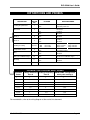
DIP SWITCHES AND PROBES
DIP
SWITCH
NO.
DESCRIPTION
Locking the parameters
1
Reserved
2
{
Probe 2
3
Probe 3
4
Probe 4
5
Cooling or heating
6 and 7
Temperature heater
8
Mist
9
Offset on ventilation stages
10
De-Icing
11
Reserved
12
POSITION
OPERATING MODE
ON
OFF
Locked parameters
Unlocked parameters
Reserved
ON
OFF
ON
OFF
Enabled
Disabled
Enabled
Disabled
ON
OFF
Enabled
Disabled
6: OFF
6: ON
6: ON
ON
OFF
ON
OFF
ON
OFF
ON
OFF
and 7: ON or OFF
and 7: ON
and 7: OFF
Stage 3 Fan
Stage 4 Fan
Stage 3 Heater
Stage 4 Heater
Stage 3 Fan
Stage 4 Heater
Zoned Heaters
Cascading Heaters
Enabled
Disabled
2°F (1.1°C) offset on ventilation stages
No offset on ventilation stages
Enabled
Disabled
Reserved
PROBES CONTROLLING HEAT ZONES
{
Activated
Probes
Probe(s) Controlling
Zone A
Probe(s) Controlling
Zone B
ROOM TEMP. averaged from
which probe reading(s)
1
1
1
1
1,2
1
2
1,2
1,3
1
3
1,3
1,4
1
4
1,4
1,2,3
1,2
3
1,2,3
1,2,4
1,2
4
1,2,4
1,3,4
1
3,4
1,3,4
1,2,3,4
1,2
3,4
1,2,3,4
For more details, refer to the wiring diagram at the end of this document.
RAYDOT Ventilation Control
Page 25
RVS-22HA User’s Guide
MOTOR TYPES
MOTOR TYPES
TYPE NUMBER
BRAND NAME
MODEL
DIAMETER
VOLTAGE
1 to 8
Other
—
—
—
9
Val-Co
Val-Co
Val-Co
Val-Co
FW08W120MSA
FW10W130MSA
PM12^140MPA
PM16^140MPA
8”
10”
12”
16”
230 V
10
Val-Co
Val-Co
Val-Co
Val-Co
PM21^140MPA
PM21^190LPA
PM24^210MPA
PM36^280M*A
21”, 3 pales
21”, 4 pales
24”
36”
230 V
Page 26
RAYDOT Ventilation Control
RVS-22HA User’s Guide
TECHNICAL SPECIFICATIONS
DESCRIPTION
VALUE
Input power
10 W
Power source (line)
115/230 VAC, -20%, +10%, 50/60 Hz
Power fuse
0.125 A @ 250 V, slow blow, 5 X 20 mm
Stages 3 and 4
10 A @ 125/250 VAC
1 HP @ 250 VAC
½ HP @ 125 VAC
Stage 1 and stage 2
10 A @ 115/230 VAC
Minimal charge: 25 mA @ 50/60 Hz
Alarm relay
1 A @ 30 VDC
Stage 1 and stage 2 power source
115/230 VAC, -20%, +10%, 50/60 Hz
(same power as line power)
Stage 1 and stage 2 fuse
15 A @ 250 VAC, slow blow
Storage temperature
-4°F to 130°F (-20°C to 55°C)
Operating temperature
32°F to 120°F (0°C to 50°C)
Temperature range – inside probes
-6.0°F to 168.6°F (-21.1°C to 75.9°C)
Weight
5.2 lbs. (2.36 kg)
Dimensions
11” X 7” X 6” (27.9 X 17.8 X 15.2 cm)
RAYDOT Ventilation Control
Page 27
RVS-22HA User’s Guide
FACTORY SETTINGS
Parameter A↑
↑ B↓
↓
Factory
Setting
Range of Values
Room Temp. Readout
Lo
Hi
Probe 1 Readout
Probe 1 Lo
Probe 1 Hi
Probe 2 Readout
Probe 2 Lo
Probe 2 Hi
Probe 3 Readout
Probe 3 Lo
Probe 3 Hi
Probe 4 Readout
Probe 4 Lo
Probe 4 Hi
Test Mode
—
—
—
—
—
—
—
—
—
—
—
—
—
—
—
OFF
-6.0 to 168.6°F (-21.1 to 75.9°C)
Software Version
2
2
SET POINT/
T°CURVE
Set Point
Adjust Day
Adjust Temperature
75.0°F (24.0°C)
—
—
-40.0 to 100.0°F (-40.0 to 40.0°C)
1 to 255
-40.0 to 100.0°F (-40.0 to 40.0°C)
CURRENT
RAMPING DAY
Current Day
Adjust Current Day
OFF
OFF
OFF, 1 to 255
MIN. SPEED/
CURVE
Minimum Speed
Adjust Day
Adjust Minimum Speed
40
—
—
12 to 100%
OFF, 1 to 255
12 to 100%
Bandwidth
Min. Ventilation On Time
Min. Ventilation Off Time
Motor Type
2.0°F (1.0°C)
15
0
10
0.5 to 20.0°F (0.3 to 11.0°C)
BANDWIDTH/
TIMER
HUMIDITY
MIN./MAX.
Readout
Lo
Hi
—
—
—
10 to 90 RH%
R.H.
COMPENSATION
Compensation Option
Humidity Set Point
R.H. Speed Compensation
OFF
65
50
ON/OFF
10 to 90 RH%
0 to 100%
OFFSET/
BANDWIDTH
Offset
Bandwidth
2.0°F (1.0°C)
0.5 to 20.0°F (0.3 to 11.0°C)
MIN. SPEED
Minimum Speed
De-icing Cycle Time
De-icing On Time
Motor Type
40
1
0
10
12 to 100%
1 to 720 minutes
0 to 900 seconds
1 to 10
Position
ROOM
TEMP.
ROOM TEMP.
MIN./MAX.
SET POINT
STAGE 1
STAGE 2
Page 28
0 to 900 seconds
1 to 10
RAYDOT Ventilation Control
RVS-22HA User’s Guide
Position
Parameter A↑
↑ B↓
↓
Factory
Setting
Range of Values
STAGE 4
DIFF.
Stage 4 Differential
2.0°F (1.0°C)
0.5 to 20.0°F (0.3 to 11.0°C)
STAGE 3
DIFF.
Stage 3 Differential
2.0°F (1.0°C)
0.5 to 20.0°F (0.3 to 11.0°C)
TIMER ON (SEC.)
TIMER OFF (MIN.)
On Time
Off Time
60
1
0 to 900 seconds
0 to 20 minutes
OFFSET/DIFF.
Offset
Differential
Humidity Turn Off
8.0°F (7.0°C)
2.0°F (1.0°C)
75
MIST
0.5 to 20.0°F (0.3 to 11.0°C)
40 to 90 RH%, OFF
HEAT 2
OFFSET/DIFF.
Offset
Differential
Max. Diff. Prot. Bet. Zones
3.0°F (3.0°C)
2.0°F (1.0°C)
7.5°F (4.2°C)
-10.0 to 20.0°F (-5.5 to 11.0°C)
0.5 to 20.0°F (0.3 to 11.0°C)
5.0 to 40.0°F (3.0 to 22.0°C), OFF
HEAT 1
OFFSET/DIFF.
Offset
Differential
3.0°F (3.0°C)
2.0°F (1.0°C)
-10.0 to 20.0°F (-5.5 to 11.0°C)
0.5 to 20.0°F (0.3 to 11.0°C)
Low Offset
10.0°F (6.0°C)
0.5 to 40.0°F (0.3 to 20.0°C)
ALARM
RV-F-1A
OPTION
INLET1
ALARM OFFSETS
RV-F-1A
OPTION
INLET2
High Offset
12.0°F (7.0°C)
0.5 to 40.0°F (0.3 to 22.0°C)
Critical High Alarm
Alarm Individual/All
95.0°F (30.0°C)
ind.
-40.0 to 120.0°F (-40.0 to 50.0°C)
ind./ALL
Inlet 1
Inlet 1 Step 0
Inlet 1 Step 1 Lo
Inlet 1 Step 1 Hi
Inlet 1 Step 2 Lo
Inlet 1 Step 2 Hi
Inlet 1 Step 3
Inlet 1 Step 4
Inlet 1 Over Open
Inlet 1 Over Bandwidth
Inlet 1 Drop
OFF
5
10
25
50
60
75
90
100
5.0°F (3.0°C)
OFF
ON/OFF
Inlet 2
Inlet 2 Step 0
Inlet 2 Step 1 Lo
Inlet 2 Step 1 Hi
Inlet 2 Step 2 Lo
Inlet 2 Step 2 Hi
Inlet 2 Step 3
Inlet 2 Step 4
Inlet 2 Over Open
Inlet 2 Over Bandwidth
Inlet 2 Drop
OFF
5
10
25
50
60
75
90
100
5.0°F (3.0°C)
OFF
RAYDOT Ventilation Control
0 to 100%
0.5 to 20.0°F (0.3 to 11.0°C)
ON/OFF
ON/OFF
0 to 100%
0.5 to 20.0°F (0.3 to 11.0°C)
ON/OFF
Page 29
RVS-22HA User’s Guide
Page 30
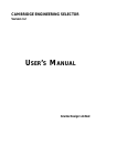
WIRING DIAGRAM RVS-22HA
117
721
For routing cable into the controller housing, drill holes at the bottom of the housing.
Do not drill holes on the sides of the housing.
W
Required clearance: 12” above controller housing, to allow for cover opening.
Provide surge protection (to include protection from lightning) from power supply to control and from
control to output extended probe. Consult a certified electrician for specific recommendations.
Line power and variable fan power must be in phase.
ON/OFF
FAN STAGE 4 FAN STAGE 3
HEATER 1
HEATER 2
MIST
MIST
ALARM
SUPPLY
SET THE VOLTAGE
SWITCH TO THE APPROPRIATE
VOLTAGE.
VARIABLE
STG 1& 2
230V
LINE VOLTAGE
SELECTOR
POWER
115/230
LINE
L2/N
L1
GND
WARNING!!!
connect probe
shield(s) to GND
terminal of
power supply
L2/N
ALARM
Set the voltage switch to the appropriate voltage.
L1
BLACK
BROWN
RED
RAYDOT Ventilation Control
WIRING DIAGRAM
RH VALCO
(Humidity Probe)
We recommend separate circuit breakers for each output stage.
IN
TEMPERATURE 4
S1
O
P
T
RMV-2
MODULE
Installation of a good quality alarm system is strongly advised to warn of power failures and high / low
temperatures.
S2
TEMPERATURE 3
Use shield for shielding purpose only. Connect the shield to the gnd of power supply.
X Y/A Z/B
TEMPERATURE 2
PROBES
G
1
2
G
3
4
G
5 / HUM
PWR
NO
C
NC
TEMPERATURE 1
GND
L2/N
(NOT INCLUDED)
BACKUP THERMOSTAT
FOR STAGE 1
L2/N
L1
FOR
SELECTION
OF OUTPUTS
SEE USER’S
GUIDE
L2/N
FAN STAGE 4 / HEATER 1 / MIST
MAX. OUTPUT 10 AMP.
FAN STAGE 1
MAX. OUTPUT 10 AMP.
L1
L1
L2/N
FAN STAGE 3 / HEATER 2 / MIST
MAX. OUTPUT 10 AMP.
FAN STAGE 2
MAX. OUTPUT 10 AMP.
L1
REV. A04
RVS-22HA User’s Guide
NOTES
RAYDOT Ventilation Control
Page 31
RVS-22HA User’s Guide
Page 32
RAYDOT Ventilation Control
MAY22 v1.3