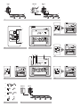
1
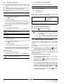
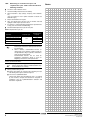
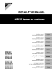
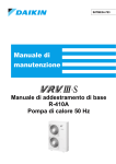
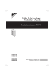
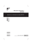
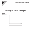
OPERATION MANUAL
and
System air conditioner
RXQ5P7W1B
RXQ8P7W1B
RXQ10P7W1B
RXQ12P7W1B
RXQ14P7W1BA
RXQ16P7W1BA
RXQ18P7W1BA
RXYQ5P7W1B
RXYQ8P7W1B
RXYQ10P7W1B
RXYQ12P7W1B
RXYQ14P7W1BA
RXYQ16P7W1BA
RXYQ18P7W1BA
RXYQ8P7W1B1
RXYQ10P7W1B1
RXYQ12P7W1B1
RXYQ14P7W1B1A
RXYQ16P7W1B1A
RXYQ18P7W1B1A
RXYSQ4P7V3B
RXYSQ5P7V3B
RXYSQ6P7V3B
RXYSQ4P7Y1B
RXYSQ5P7Y1B
RXYSQ6P7Y1B
1
RXQ
5
RXYSQ
1
1
RXYQ
5
4
5
1
4
6 4
6
5
2
5
2
5
3
4
3
4
1
4.1
3
2
1
1
2
2+3
1
4.1
1
2
4.2
2
1
3
2+3
1
6
1
4 2
3
4.2
UNIT NO.
4.3
5
3+5
1
1
2
1
4
5
7
6
A
8
RXYSQ
B
C
D
7
8
RXYQ
4.3
2+3
RX(Y)Q5~12P7W1B
RX(Y)Q14~18P7W1BA
RXYQ8~12P7W1B1
RXYQ14~18P7W1B1A
RXYQ8~12P7W1B1
RXYSQ4~6P7V3B
RXYSQ4~6P7Y1B
VRVIII and VRVIII-S system air conditioner
CONTENTS
1.
2.
3.
4.
5.
6.
7.
Page
Safety cautions .......................................................................... 1
Important information regarding the refrigerant used ................ 2
What to do before operation ...................................................... 2
Remote controller....................................................................... 2
Changeover switch: Name and function of each switch ............. 2
Operation range ......................................................................... 3
Operation procedure .................................................................. 3
7.1.
7.2.
7.3.
7.4.
7.5.
Cooling, heating, fan only, and automatic operation .................... 3
Program dry operation ................................................................. 4
Adjusting the air flow direction ..................................................... 4
Setting the master remote controller ............................................ 4
Precautions for group control system or two remote controller
control system .............................................................................. 5
8. Energy saving and optimum operation ...................................... 5
9. Maintenance .............................................................................. 5
■
Do not place objects in direct proximity of the outdoor unit and
do not let leaves and other debris accumulate around the unit.
Leaves are a hotbed for small animals which can enter the unit.
Once in the unit, such animals can cause malfunctions, smoke
or fire when making contact with electrical parts.
■
Ask your dealer for improvement, repair, and maintenance.
Incomplete improvement, repair, and maintenance may result in
a water leakage, electric shock, and fire.
■
Do not insert fingers, rods or other objects into the air inlet or
outlet. When the fan is rotating at high speed, it will cause injury.
■
Never let the indoor unit or the remote controller get wet.
It may cause an electric shock or a fire
■
Never use a flammable spray such as hair spray, lacquer or paint
near the unit.
It may cause a fire.
■
Never touch the air outlet or the horizontal blades while the
swing flap is in operation.
Fingers may become caught or the unit may break down.
■
Never replace a fuse with that of wrong ampere ratings or other
wires when a fuse blows out.
Use of wire or copper wire may cause the unit to break down or
cause a fire.
■
Never put any objects into the air inlet or outlet.
Objects touching the fan at high operating speed can be
dangerous.
■
Never press the button of the remote controller with a hard,
pointed object.
The remote controller may be damaged.
■
Never pull or twist the electric wire of the remote controller.
It may cause the unit to malfunction.
■
Never inspect or service the unit by yourself.
Ask a qualified service person to perform this work.
■
To prevent refrigerant leak, contact your dealer.
When the system is installed and runs in a small room, it is
required to keep the concentration of the refrigerant, if by any
chance coming out, below the limit. Otherwise, oxygen in the
room may be affected, resulting in a serious accident.
■
The refrigerant in the air conditioner is safe and normally does
not leak. If the refrigerant leaks in the room, contact with a fire of
a burner, a heater or a cooker may result in a harmful gas.
Turn off any combustible heating devices, ventilate the room,
and contact the dealer where you purchased the unit.
Do not use the air conditioner until a service person confirms
that the portion where the refrigerant leaks is repaired.
■
Improper installation or attachment of equipment or accessories
could result in electric shock, short-circuit, leaks, fire, or other
damage to the equipment. Be sure to use only accessories
made by Daikin which are specifically designed for use with the
equipment and have them installed by a professional.
■
Ask your dealer to move and reinstall the air conditioner.
Incomplete installation may result in a water leakage, electric
shock, and fire.
9.1. Maintenance after a long stop period........................................... 5
9.2. Maintenance before a long stop period........................................ 5
10. Following symptoms are not air conditioner troubles ................. 5
11. Troubleshooting.......................................................................... 6
12. After-sales service and warranty................................................ 7
12.1. After-sales service ....................................................................... 7
12.2. Shortening of "maintenance cycle" and "replacement cycle"
needs to be considered in following situations ............................. 8
Thank you for purchasing this Daikin air conditioner.
Carefully read this operation manual before using the air
conditioner. It will tell you how to use the unit properly and
help you if any trouble occurs. After reading the manual,
file it away for future reference.
1.
SAFETY
CAUTIONS
Read the following cautions carefully and use your equipment
properly.
WARNING
Improper handling can lead to such serious consequences
as death, severe injury or damage to the equipment.
NOTE
These instructions will ensure proper use of the
equipment.
Be sure to follow these important safety cautions.
Keep these warning sheets handy so that you can refer to them
if needed.
Also, if this equipment is transferred to a new user, make sure to
hand over this user's manual to the new user.
Warnings
■
It is not good for your health to expose your body to the air flow
for a long time.
■
In order to avoid electric shock, fire or injury, or if you detect any
abnormality such as smell of fire, turn off the power supply and
call your dealer for instructions.
■
Ask your dealer for installation of the air conditioner.
Incomplete installation performed by yourself may result in a
water leakage, electric shock, and fire.
RX(Y)Q5~18P7W1B(A) + RXYQ8~18P7W1B1(A) + RXYSQ4~6P7V3B +
RXYSQ4~6P7Y1B
VRVIII and VRVIII-S system air conditioner
4PW35770-1B
Operation manual
Operation manual
1
Cautions
■
Do not operate the air conditioner when using a room fumigation
- type insecticide.
Failure to observe could cause the chemicals to become
deposited in the unit, which could endanger the health of those
who are hypersensitive to chemicals.
■
Do not use the air conditioner for other purposes.
In order to avoid any quality deterioration, do not use the unit for
cooling precision instruments, food, plants, animals or works of
art.
■
■
In order to avoid injury, do not remove the fan guard of the
outdoor unit.
Do not touch the heat exchanger fins.
These fins are sharp and could result in cutting injuries.
■
■
To avoid oxygen deficiency, ventilate the room sufficiently if
equipment with burner is used together with the air conditioner.
The appliance is not intended for use by young children or infirm
persons without supervision.
■
■
After a long use, check the unit stand and fitting for damage.
If damaged, the unit may fall and result in injury.
Young children should be supervised to ensure that they do not
play with the appliance.
■
Do not place a flammable spray bottle near the air conditioner
and do not use sprays.
Doing so may result in a fire.
2.
■
Before cleaning, be sure to stop the operation, turn the breaker
off or pull out the supply cord.
Otherwise, an electric shock and injury may result.
This product contains fluorinated greenhouse gases covered by the
Kyoto Protocol.
■
Do not operate the air conditioner with a wet hand.
An electric shock may result.
Refrigerant type:
R410A
GWP(1) value:
1975
■
■
Do not place items which might be damaged by moisture under
the indoor unit.
Condensation may form if the humidity is above 80%, if the drain
outlet is blocked or the filter is polluted.
Do not place appliances which produce open fire in places
exposed to the air flow from the unit or under the indoor unit. It
may cause incomplete combustion or deformation of the unit
due to the heat.
(1)
IMPORTANT
INFORMATION REGARDING
THE REFRIGERANT USED
GWP = global warming potential
Periodical inspections for refrigerant leaks may be required
depending on European or local legislation. Please contact your local
dealer for more information.
3.
WHAT
TO DO BEFORE OPERATION
■
Do not allow anyone to mount on the outdoor unit or avoid
placing any object on it.
Falling or tumbling may result in injury.
This operation manual is for the following systems with standard
control. Before initiating operation, contact your dealer for the
operation that corresponds to your system type and mark.
■
Never expose little children, plants or animals directly to the air
flow.
Adverse influence to little children, animals and plants may
result.
If your installation has a customized control system, ask your dealer
for the operation that corresponds to your system.
■
Do not wash the air conditioner with water.
Electric shock or fire may result.
■
Do not install the air conditioner at any place where flammable
gas may leak out.
If the gas leaks out and stays around the air conditioner, a fire
may break out.
■
In order to avoid electric shock or fire, make sure that an earth
leak detector is installed.
■
Be sure the air conditioner is electrically earthed.
In order to avoid electric shock, make sure that the unit is
grounded and that the earth wire is not connected to gas or
water pipe, lightning conductor or telephone earth wire.
Outdoor units (See figure 1)
Cool/heat
changeover remote
control switch
Cooling only RXQ series
Heat pumps RXYQ series
❏ yes
❏ no
Heat pumps RXYSQ series
❏ yes
❏ no
Names and functions of parts (See figure 1)
1
Outdoor unit
2
Indoor unit
■
Arrange the drain hose to ensure smooth drainage. Incomplete
drainage may cause wetting of the building, furniture etc.
3
Remote controller
4
Inlet air
■
Do not let children play on and around the outdoor unit.
If they touch the unit carelessly, it may result in injury.
5
Outlet air
6
Cool/heat changeover remote control switch
■
Do not place a flower vase or anything containing water on the
unit.
Water may enter the unit, causing an electric shock or fire.
■
Do not place the controller exposed to direct sunlight.
The LCD display may get discolored, failing to display the data.
■
Do not wipe the controller operation panel with benzine, thinner,
chemical dustcloth, etc.
The panel may get discolored or the coating peeled off. If it is
heavily dirty, soak a cloth in water-diluted neutral detergent,
squeeze it well and wipe the panel clean. And wipe it with
another dry cloth.
■
Never touch the internal parts of the controller.
Do not remove the front panel. Some parts inside are dangerous
to touch, and a machine trouble may happen. For checking and
adjusting the internal parts, contact your dealer.
■
Avoid placing the controller in a spot splashed with water.
Water coming inside the machine may cause an electric leak or
may damage the internal electronic parts.
Operation manual
2
Operation modes
(figure 1 shows systems with changeover remote control switches.)
4.
REMOTE
CONTROLLER
Refer to the operation manual of the remote controller.
5.
CHANGEOVER SWITCH: NAME AND
FUNCTION OF EACH SWITCH (See figure 2)
1
FAN ONLY/AIR CONDITIONING SELECTOR SWITCH
Set the switch to
for fan only operation or to
for heating or
cooling operation.
2
COOL/HEAT CHANGEOVER SWITCH
Set the switch to
for cooling or to
for heating operation.
RX(Y)Q5~18P7W1B(A) + RXYQ8~18P7W1B1(A) + RXYSQ4~6P7V3B +
RXYSQ4~6P7Y1B
VRVIII and VRVIII-S system air conditioner
4PW35770-1B
6.
OPERATION
RANGE
For systems with cool/heat changeover remote control switch
1
Operation range
Select operation mode with the cool/heat changeover remote
control switch as follows:
Use the system in the following temperature and humidity ranges for
safe and effective operation.
RXQ5~18
RXYQ5~18
RXYQ5~18
RXYSQ4~6
–5~43°C DB
–20~21°C DB
–5~46°C DB –20~24°C DB(*)
Cooling operation (figure 4.1)
Heating operation (figure 4.2)
Fan only operation (figure 4.3)
Outdoor
temperature
Indoor
temperature
Indoor
humidity
–20~15.5°C WB
21~32°C DB
15~27°C DB
14~25°C WB
–20~15.5°C WB
21~32°C DB
≤80%(†)
(*) Range for operation: –20~–15°C WB. Range for continuous operation:
–15~15.5°C WB.
(†) to avoid condensation and water dripping out the unit.
If the temperature or the humidity is beyond these conditions, safety devices may
work and the air conditioner may not operate.
Press the on/off button.
The operation lamp lights up and the system starts operation.
15~27°C DB
14~25°C WB
≤80%(†)
2
Adjustment
For programming temperature, fan speed and air flow direction, refer
to the operation manual of the remote controller.
Stopping the system
3
Press the on/off button once again.
The operation lamp goes off and the system stops operation.
7.
■
OPERATION
PROCEDURE
NOTE
Do not turn off power immediately after the unit stops,
but wait for at least 5 minutes.
Operation procedure varies according to the combination of
outdoor unit and remote controller. Read "3. What to do before
operation" on page 2.
Explanation of heating operation
■
To protect the unit, turn on the main power switch 6 hours before
operation.
It may take longer to reach the set temperature for general heating
operation than for cooling operation.
■
If the main power supply is turned off during operation, operation
will restart automatically after the power turns back on again.
7.1.
Cooling, heating, fan only, and automatic
operation (See figure 3 and figure 4.1)
The following operation is performed in order to prevent the heating
capacity from dropping or cold air from blowing.
Defrost operation (heat pump and heat recovery types only)
■
In heating operation, freezing of the outdoor unit coil increases.
Heating capability decreases and the system goes into defrost
operation.
■
Changeover cannot be made with a remote controller whose
display shows
(change-over under centralized control).
■
■
When the display
(change-over under centralized control)
flashes, refer to "7.4. Setting the master remote controller" on
page 4.
The indoor unit fan stops and the remote controller displays
.
■
After maximum 10 minutes of defrost operation, the system
returns to heating operation again.
■
RXQ series let you select fan only and cooling operation.
Hot start (heat pump and heat recovery types only)
■
The fan may keep on running for about 1 minute after the
heating operation stops.
■
■
The air flow rate may adjust itself depending on the room
temperature or the fan may stop immediately. This is not a
malfunction.
For systems without cool/heat changeover remote control
switch (See figure 3)
1
In order to prevent cold air from blowing out of an indoor unit at
the start of heating operation, the indoor fan is automatically
stopped. The display of the remote controller shows
.
It may take some time before the fan starts. This is not a
malfunction.
NOTE
■
The heating capacity drops when the outside
temperature falls. If this happens, use another
heating device together with the unit. (When using
together with appliances that produce open fire,
ventilate the room constantly.)
Do not place appliances that produce open fire in
places exposed to the air flow from the unit or
under the unit.
■
It takes some time to heat up the room from the
time the unit is started since the unit uses a hot-air
circulating system to heat the entire room.
■
If the hot air rises to the ceiling, leaving the area
above the floor cold, we recommend that you use
the circulator (the indoor fan for circulating air).
Contact your dealer for details.
Press the operation mode selector button several times and
select the operation mode of your choice.
Cooling operation
Heating operation
Fan only operation
2
Press the on/off button.
The operation lamp lights up and the system starts operation.
RX(Y)Q5~18P7W1B(A) + RXYQ8~18P7W1B1(A) + RXYSQ4~6P7V3B +
RXYSQ4~6P7Y1B
VRVIII and VRVIII-S system air conditioner
4PW35770-1B
Operation manual
3
7.2.
■
Program dry operation
The function of this program is to decrease the humidity in your
room with minimal temperature decrease (minimal room
cooling).
■
The micro computer automatically determines temperature and
fan speed (cannot be set by the remote controller).
■
The system does not go into operation if the room temperature
is low (<20°C).
For systems without cool/heat changeover remote control
switch
1
2
7.3.
Refer to the operation manual of the remote controller.
Movement of the air flow flap (See figure 7)
Double-flow + Multi-flow units
B
Corner units
C
Ceiling-suspended units
D
Wall-mounted units
Press the operation mode selector button several times and
select
(program dry operation).
Press the on/off button.
Press the air flow direction adjust button. (Only for Double-flow,
Multi-flow, Corner, Ceiling-suspended and Wall-mounted.) Refer
to "7.3. Adjusting the air flow direction" on page 4 for details.
Stopping the system
4
A
For the following conditions, a micro computer controls the air flow
direction which may be different from the display.
The operation lamp lights up and the system starts operation.
3
Press the on/off button once again.
The operation lamp goes off and the system stops operation.
NOTE
COOLING
HEATING
• When the room temperature is lower than
the set temperature.
• When starting operation.
• When the room temperature is higher than
the set temperature.
• At defrost operation.
• When operating continuously at horizontal air flow direction.
• When continuous operation with downward air flow is performed at the time of cooling with a
ceiling-suspended or a wall-mounted unit, the microcomputer may control the flow direction,
and then the remote control indication also will change.
The air flow direction can be adjusted in one of the following ways.
■
The air flow flap itself adjusts its position.
■
The air flow direction can be fixed by the user.
■
Automatic "
Do not turn off power immediately after the unit stops,
but wait for at least 5 minutes.
NOTE
For systems with cool/heat changeover remote control switch
(See figure 5)
1
Select cooling operation mode with the cool/heat changeover
remote control switch.
2
Press the operation mode selector button several times and
select
(program dry operation).
7.4.
3
4
" and desired position "
".
■
The movable limit of the flap is changeable.
Contact your dealer for details. (Only for Doubleflow, Multi-flow, Corner, Ceiling-suspended and
Wall-mounted.)
■
Avoid operating in the horizontal direction
"
". It may cause dew or dust to settle on the
ceiling.
Setting the master remote controller
Press the on/off button.
When the system is installed as shown in figure 8, it is necessary to
designate one of the remote controllers as the master remote
controller.
The operation lamp lights up and the system starts operation.
■
Only the master remote controller can select heating or cooling
operation.
■
The displays of slave remote controllers show
(changeover under centralized control) and they automatically follow the
operation mode directed by the master remote controller.
Press the air flow direction adjust button. (Only for Double-flow,
Multi-flow, Corner, Ceiling-suspended and Wall-mounted.) Refer
to "7.3. Adjusting the air flow direction" on page 4 for details.
Stopping the system
5
Adjusting the air flow direction
Press the on/off button once again.
The operation lamp goes off and the system stops operation.
However, it is possible to changeover to program dry with slave
remote controllers if the system is in cooling operation set by the
master remote controller.
How to designate the master remote controller
NOTE
Do not turn off power immediately after the unit stops,
but wait for at least 5 minutes.
1
Press the operation mode selector button of the current master
remote controller for 4 seconds.
The display showing
(change-over under centralized
control) of all slave remote controllers connected to the same
outdoor unit or BS unit flash.
2
Press the operation mode selector button of the controller that
you wish to designate as the master remote controller. Then
designation is completed. This remote controller is designated
as the master remote controller and the display showing
(change-over under centralized control) vanishes.
The displays of other remote controllers show
over under centralized control).
Operation manual
4
(change-
RX(Y)Q5~18P7W1B(A) + RXYQ8~18P7W1B1(A) + RXYSQ4~6P7V3B +
RXYSQ4~6P7Y1B
VRVIII and VRVIII-S system air conditioner
4PW35770-1B
7.5.
Precautions for group control system or two
remote controller control system
9.
MAINTENANCE
This system provides two other control systems beside individual
control (one remote controller controls one indoor unit) system.
Confirm the following if your unit is of the following control system
type.
■
Group control system
One remote controller controls up to 16 indoor units. All indoor
units are equally set.
■
Two remote controller control system
Two remote controllers control one indoor unit (in case of group
control system, one group of indoor units). The unit is
individually operated.
NOTE
8.
Contact your dealer in case of changing the
combination or setting of group control and two remote
controller control systems.
ENERGY SAVING AND OPTIMUM
OPERATION
Observe the following precautions to ensure the system operates
properly.
■
Adjust the air outlet properly and avoid direct air flow to room
inhabitants.
■
Adjust the room temperature properly for a comfortable
environment. Avoid excessive heating or cooling.
■
Prevent direct sunlight from entering a room during cooling
operation by using curtains or blinds.
■
Ventilate often.
Extended use requires special attention to ventilation.
■
Keep doors and windows closed. If the doors and windows
remain open, air will flow out of your room causing a decrease in
the cooling or heating effect.
■
Be careful not to cool or heat too much. To save energy, keep
the temperature setting at a moderate level.
Recommended temperature setting
For cooling
26~28°C
For heating
20~24°C
■
Never place objects near the air inlet or the air outlet of the unit.
It may cause deterioration in the effect or stop the operation.
■
Turn off the main power supply switch to the unit when the unit is
not used for longer periods of time. If the switch is on, it uses
electricity. Before restarting the unit, turn on the main power
supply switch 6 hours before operation to ensure smooth
running. (Refer to "Maintenance" in the indoor unit manual.)
■
When the display shows
(time to clean the air filter), ask a
qualified service person to clean the filters. (Refer to
"Maintenance" in the indoor unit manual.)
■
Keep the indoor unit and remote control at least 1 m away from
televisions, radios, stereos, and other similar equipment.
Failing to do so may cause static or distorted pictures.
■
Do not place items under the indoor unit which may be damaged
by water.
Condensation may form if the humidity is above 80% or if the
drain outlet gets blocked.
RX(Y)Q5~18P7W1B(A) + RXYQ8~18P7W1B1(A) + RXYSQ4~6P7V3B +
RXYSQ4~6P7Y1B
VRVIII and VRVIII-S system air conditioner
4PW35770-1B
Pay attention to the fan.
It is dangerous to inspect the unit while the fan is running.
Be sure to turn off the main switch and to remove the fuses
from the control circuit located in the outdoor unit.
9.1.
Maintenance after a long stop period (e.g. at the
beginning of the season)
■
Check and remove everything that might be blocking inlet and
outlet vents of indoor units and outdoor units.
■
Clean air filters and casings of indoor units. Refer to the
operation manual supplied with the indoor units for details on
how to proceed and make sure to install cleaned air filters back
in the same position.
■
Turn on the power at least 6 hours before operating the unit in
order to ensure smoother operation. As soon as the power is
turned on, the remote controller displays appear.
9.2.
Maintenance before a long stop period (e.g. at
the end of the season)
■
Let the indoor units run in fan only operation for about half a day
in order to dry the interior of the units. Refer to "7.1. Cooling,
heating, fan only, and automatic operation" on page 3 for details
on fan only operation.
■
Turn off the power. The remote controller displays disappear.
■
Clean air filters and casings of indoor units. Refer to the
operation manual supplied with the indoor units for details on
how to proceed and make sure to install cleaned air filters back
in the same position.
10. FOLLOWING
SYMPTOMS ARE NOT AIR
CONDITIONER TROUBLES
Symptom 1: The system does not operate
■
The air conditioner does not start immediately after the ON/OFF
button on the remote controller is pushed.
If the operation lamp lights, the system is in normal condition.
To prevent overloading of the compressor motor, the air
conditioner starts 5 minutes after it is turned ON again in case it
was turned OFF just before. The same starting delay occurs
after the operation mode selector button was used.
■
If "Centralized Control" is displayed on the remote control and
pressing the operation button causes the display to blink for a
few seconds.
This indicates that the central device is controlling the unit.
The blinking display indicates that the remote control cannot be
used.
■
The system does not start immediately after the power supply is
turned on.
Wait one minute until the micro computer is prepared for
operation.
Symptom 2: Cool/Heat cannot be changed over
■
When the display shows "
" (change-over under
centralized control), it shows that this is a slave remote
controller.
■
When the cool/heat changeover remote control switch is
installed and the display shows "
" (change-over under
centralized control).
This is because cool/heat changeover is controlled by the cool/
heat changeover remote control switch. Ask your dealer where
the remote control switch is installed.
Operation manual
5
Symptom 3: Fan operation is possible, but cooling and heating do not
work.
■
Symptom 8.2: Indoor unit, outdoor unit
■
A continuous low hissing sound is heard when the system is in
cooling or defrost operation.
This is the sound of refrigerant gas flowing through both indoor
and outdoor units.
■
A hissing sound which is heard at the start or immediately after
stopping operation or defrost operation.
This is the noise of refrigerant caused by flow stop or flow
change.
Immediately after the power is turned on.
The micro computer is getting ready to operate. Wait 10
minutes.
Symptom 4: The fan strength does not correspond to the setting.
■
The fan strength does no change even if the fan strength
adjustment button in pressed.
During heating operation, when the room temperature reaches
the set temperature, the outdoor unit goes off and the indoor unit
changes to whisper fan strength.
This is to prevent cold air blowing directly on occupants of the
room.
The fan strength will not change even if the button is changed,
when another indoor unit is in heating operation.
Symptom 8.3: Outdoor unit
■
When the tone of operating noise changes.
This noise is caused by the change of frequency.
Symptom 9: Dust comes out of the unit
■
When the unit is used for the first time in a long time.
This is because dust has gotten into the unit.
Symptom 5: The fan direction does not correspond to the setting
■
The fan direction does not correspond to the remote control
display. The fan direction does not swing.
This is because the unit is being controlled by the micro
computer.
Symptom 10: The units can give off odours
■
The unit can absorb the smell of rooms, furniture, cigarettes,
etc., and then emit it again.
Symptom 11: The outdoor unit fan does not spin.
Symptom 6: White mist comes out of a unit
■
Symptom 6.1: Indoor unit
■
■
When humidity is high during cooling operation
If the interior of an indoor unit is extremely contaminated, the
temperature distribution inside a room becomes uneven. It is
necessary to clean the interior of the indoor unit. Ask your dealer
for details on cleaning the unit. This operation requires a
qualified service person.
Immediately after the cooling operation stops and if the room
temperature and humidity are low.
This is because warm refrigerant gas flows back into the indoor
unit and generates steam.
During operation.
The speed of the fan is controlled in order to optimize product
operation.
".
This is the case immediately after the main power supply switch
is turned on and means that the remote controller is in normal
condition. This continues for one minute.
Symptom 12: The display shows "
■
Symptom 13: The compressor in the outdoor unit does not stop after a
short heating operation
■
This is to prevent oil and refrigerant from remaining in the
compressor. The unit will stop after 5 to 10 minutes.
Symptom 6.2: Indoor unit, outdoor unit
■
When the system is changed over to heating operation after
defrost operation
Moisture generated by defrost becomes steam and is
exhausted.
Symptom 7: The remote controller display reads "U4" or "U5" and stops,
but then restarts after a few minutes
■
This is because the remote control is intercepting noise from
electric appliances other than the air conditioner. This prevents
communication between the units, causing them to stop.
Operation automatically restarts when the noise ceases.
Symptom 8: Noise of air conditioners
Symptom 8.1: Indoor unit
■
■
■
■
A "zeen" sound is heard immediately after the power supply is
turned on.
The electronic expansion valve inside an indoor unit starts
working and makes the noise. Its volume will reduce in about
one minute.
■
A "pishi-pishi" squeaking sound is heard when the system stops
after heating operation.
Expansion and contraction of plastic parts caused by
temperature change make this noise.
A low "sah", "choro-choro" sound is heard while the indoor unit
is stopped.
When the other indoor unit is in operation, this noise is heard. In
order to prevent oil and refrigerant from remaining in the system,
a small amount of refrigerant is kept flowing.
This is because the crankcase heater is warming the
compressor so that the compressor can start smoothly.
Symptom 15: Hot air can be felt when the indoor unit is stopped
■
Several different indoor units are being run on the same system.
When another unit is running, some refrigerant will still flow
through the unit.
11. TROUBLESHOOTING
If one of the following malfunctions occur, take the measures shown
below and contact your dealer.
WARNING
Stop operation and shut off the power if anything
unusual occurs (burning smells, etc.)
A continuous low "shah" sound is heard when the system is in
cooling operation or at a stop
When the drain pump (optional accessories) is in operation, this
noise is heard.
Operation manual
6
Symptom 14: The inside of an outdoor unit is warm even when the unit
has stopped
Leaving the unit running under such circumstances may
cause breakage, electric shock, or fire.
Contact your dealer.
The system must be repaired by a qualified service person.
■
If a safety device such as a fuse, a breaker or an earth leakage
breaker frequently actuates, or the ON/OFF switch does not
properly work.
Measure: Turn off the main power switch.
■
If water leaks from unit
Measure: Stop the operation.
■
The operation switch does not work well.
Measure: Turn off the power.
RX(Y)Q5~18P7W1B(A) + RXYQ8~18P7W1B1(A) + RXYSQ4~6P7V3B +
RXYSQ4~6P7Y1B
VRVIII and VRVIII-S system air conditioner
4PW35770-1B
■
Our network of dealers has access to a permanent stock of
essential components in order to keep your air conditioner in
operation as long as possible.
Contact your dealer for more information.
TEST , the unit number and the operation lamp
If the display
flash and the malfunction code appears. (See figure 6)
1
Inspection display
2
Indoor unit number in which a malfunction occurs
3
Operation lamp
4
Malfunction code
■
Measure: Notify your dealer and report the malfunction code.
If the system does not properly operate except for the above
mentioned cases and none of the above mentioned malfunctions is
evident, investigate the system according to the following
procedures.
1
If the system does not operate at all
■
Check if there is no power failure.
Wait until power is restored. If power failure occurs during
operation, the system automatically restarts immediately after
the power supply is recovered.
■
Check if no fuse has blown or breaker has worked. Change the
fuse or reset the breaker if necessary.
2
If the system goes into fan only operation, but as soon as it
goes into heating or cooling operation, the system stops
■
Check if air inlet or outlet of outdoor or indoor unit is not blocked
by obstacles. Remove any obstacle and make it well-ventilated.
■
Check if the remote controller display shows "
" (time to
clean the air filter). (Refer to "Maintenance" in the indoor unit
manual.)
3
The system operates but cooling or heating is insufficient
■
Check if air inlet or outlet of outdoor or indoor unit is not blocked
by obstacles.
■
Remove any obstacle and make it well-ventilated.
■
Check if the air filter is not clogged. (Refer to "Maintenance" in
the indoor unit manual.)
■
■
■
■
Check the temperature setting.
Check the fan speed setting on your remote controller.
Check for open doors or windows. Shut doors and windows to
prevent wind from coming in.
Check if there are too many occupants in the room during
cooling operation
When asking your dealer for an intervention, always state:
• the complete model name of the air conditioner
• the manufacturing number (stated on the nameplate of the
unit)
• the installation date
• the symptoms or malfunction, and details of the defect.
WARNING
■
■
Do not modify, disassemble, remove, reinstall or
repair the unit yourself as incorrect dismantling or
installation may cause an electric shock or fire.
Contact your dealer.
■
In case of accidental refrigerant leaks, make sure
there are no naked flames. The refrigerant itself is
entirely safe, non-toxic and non-combustible, but it will
generate toxic gas when it accidentally leaks into a
room where combustible air from fan heaters, gas
cookers, etc. ... is present.
Always have qualified service personnel confirm that
the point of leakage has been repaired or corrected
before resuming operation.
Recommended inspection and maintenance cycles
Be aware that the mentioned maintenance and replacement cycles
do not relate to the warranty period of the components.
Table 1: "Inspection Cycle" and "Maintenance Cycle" list
Component
Inspection cycle
Maintenance cycle
(replacements and/
or repairs)
Electric motor
20,000 hours
PCB
25,000 hours
Heat exchanger
5 years
Sensor (thermistor, etc.)
Remote controller and switches
1 year
Drain pan
5 years
25,000 hours
8 years
Expansion valve
20,000 hours
Electromagnetic valve
20,000 hours
■
Check if the heat source of the room is excessive.
Table 1 assumes the following conditions of use:
■
Check if direct sunlight enters the room. Use curtains or blinds.
1.
■
Check if the air flow angle is proper.
Normal use without frequent starting and stopping of the unit.
Depending on the model, we recommend not starting and
stopping the machine more than 6 times/hour.
2.
Operation of the unit is assumed to be 10 hours/day and 2,500
hours/year.
If after checking all above items, it is impossible to fix the problem
yourself, contact your dealer and state the symptoms, the complete
model name of the air conditioner (with manufacturing number if
possible) and the installation date (possibly listed on the warranty card).
NOTE
12. AFTER-SALES
SERVICE AND WARRANTY
Warranty period
■
This product includes a warranty card that was filled out by the
dealer at the time of installation. The completed card was
checked by the customer and stored carefully.
■
If repairs to the air conditioner are necessary within the warranty
period, contact your dealer and keep the warranty card at hand.
1.
Table 1 indicates main components.
Refer to your maintenance and inspection contract
for more details.
2.
Table 1 indicates recommended intervals of
maintenance cycles. However, in order to keep the
unit operational as long as possible, maintenance
work may be required sooner.
Recommended intervals can be used for
appropriate maintenance design in terms of
budgetting maintenance and inspection fees.
Depending on the content of the maintenance and
inspection contract, inspection and maintenance
cycles may in reality be shorter than listed.
12.1. After-sales service
■
Recommendations for maintenance and inspection
Since dust collects when using the unit for several years,
performance of the unit will deteriorate to some extent.
As taking apart and cleaning interiors of units requires technical
expertise and in order to ensure the best possible maintenance
of your units, we recommend to enter into a maintenance and
inspection contract on top of normal maintenance activities.
RX(Y)Q5~18P7W1B(A) + RXYQ8~18P7W1B1(A) + RXYSQ4~6P7V3B +
RXYSQ4~6P7Y1B
VRVIII and VRVIII-S system air conditioner
4PW35770-1B
Operation manual
7
12.2. Shortening of "maintenance cycle" and
"replacement cycle" needs to be considered in
following situations
■
The unit is used in locations where:
1.
heat and humidity fluctuate out of the ordinary
2.
power fluctuation is high (voltage, frequency, wave distortion,
etc.)
(The unit cannot be used if power fluctuation is outside the
allowable range.)
3.
bumps and vibrations are frequent
4.
dust, salt, harmful gas or oil mist such as sulfurous acid and
hydrogen sulfide may be present in the air
5.
the machine is started and stopped frequently or operation time
is long (sites with 24 hour air-conditioning).
■
Recommended replacement cycle of wear parts
NOTES
Table 2: Replacement Cycle" list
Component
Inspection cycle
Air filter
5 years
High efficiency filter (Optional)
Fuse
Crankcase heater
NOTE
Maintenance cycle
(replacements and/
or repairs)
1 year
1 year
10 years
8 years
1.
Table 2 indicates main components.
Refer to your maintenance and inspection contract
for more details.
2.
Table 2 indicates recommended intervals of
replacement cycles. However, in order to keep the
unit operational as long as possible, maintenance
work may be required sooner.
Recommended intervals can be used for
appropriate maintenance design in terms of
budgetting maintenance and inspection fees.
Contact your dealer for details.
NOTE
■
Damage due to taking apart or cleaning interiors of
units by anyone other than our authorised dealers may
not be included in the warranty.
Moving and discarding the unit
■ Contact your dealer for removing and reinstalling the total
unit. Moving units requires technical expertise.
■ This unit uses hydrofluorocarbon.
Contact your dealer when discarding this unit. It is required
by law to collect, transport and discard the refrigerant in
accordance with the "hydrofluorocarbon collection and
destruction" regulations.
Operation manual
8
RX(Y)Q5~18P7W1B(A) + RXYQ8~18P7W1B1(A) + RXYSQ4~6P7V3B +
RXYSQ4~6P7Y1B
VRVIII and VRVIII-S system air conditioner
4PW35770-1B
NOTES
Zandvoordestraat 300, B-8400 Oostende, Belgium
4PW35770-1B