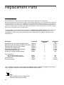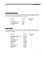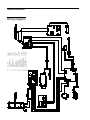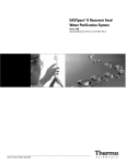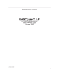
1
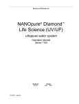
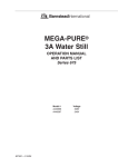
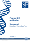
EASYpure® II UV/UF
OPERATION MANUAL
AND PARTS LIST
Series 1304
Model D8611
100-240 Volts
LT1304X1 • 4/10/03
Table of Contents
Safety Information ..............................................................................................................................................4
Alert Signals..................................................................................................................................................4
Warnings ......................................................................................................................................................4
Introduction ........................................................................................................................................................6
Product Overview ........................................................................................................................................6
General Specifications ........................................................................................................................................7
Dimensions and Clearance Requirements ..................................................................................................7
Electrical Requirements................................................................................................................................7
Feedwater and Drain Requirements ............................................................................................................7
Product Water Quality ..................................................................................................................................7
Environmental Conditions ............................................................................................................................8
Declaration of Conformity ............................................................................................................................8
Unpacking ........................................................................................................................................................9
Unpacking ....................................................................................................................................................9
Installation ......................................................................................................................................................10
Water Connection Details ..........................................................................................................................10
Push-to-Connect Fitting Tubing Installation ........................................................................................10
Tubing Adapter Fittings ..............................................................................................................................11
Quick Disconnect Fittings ..........................................................................................................................12
Component Installation ..............................................................................................................................13
UV Lamp Installation ............................................................................................................................13
Ultrafilter Installation ............................................................................................................................15
Initial Cartridge Installation ..................................................................................................................16
Locating and Mounting Unit........................................................................................................................17
Bench Mounting ..................................................................................................................................17
Wall Mounting ......................................................................................................................................17
Remote Dispenser................................................................................................................................18
Tube Connections ................................................................................................................................18
Remote Dispenser Wall Bracket Mounting ..........................................................................................19
Water Service Connections ........................................................................................................................19
Atmospheric Drain................................................................................................................................19
Feedwater ............................................................................................................................................20
Power Connections ....................................................................................................................................20
Air Purge ....................................................................................................................................................21
Controls and Normal Operation ........................................................................................................................22
Power Switch ..............................................................................................................................................22
Control Panel ..............................................................................................................................................22
Switches ..............................................................................................................................................22
Display..................................................................................................................................................22
Operational Modes ....................................................................................................................................23
Run Mode ............................................................................................................................................23
Standby ................................................................................................................................................23
Flush ....................................................................................................................................................23
Manual Flush ................................................................................................................................24
Automatic Flush ............................................................................................................................24
Idle Mode..............................................................................................................................................24
Dispensing Water From Unit ......................................................................................................................25
2
TABLE
OF
CONTENTS
Dispensing Water from Remote..................................................................................................................25
Maintenance and Servicing ..............................................................................................................................26
Sanitization ................................................................................................................................................26
Cleaning the Resistivity Cell ................................................................................................................28
General Cleaning Instructions ..............................................................................................................30
Component Replacement ..........................................................................................................................30
Cartridge Replacement and Rinse Up ................................................................................................30
UV Lamp Replacement ........................................................................................................................31
Ultrafilter Replacement ........................................................................................................................33
0.2 Micron Final Filter Replacement ....................................................................................................33
Fuse Replacement ..............................................................................................................................34
Unit Shutdown ............................................................................................................................................34
Troubleshooting ................................................................................................................................................35
Error Conditions..........................................................................................................................................37
Replacement Parts............................................................................................................................................38
Consumables ..............................................................................................................................................38
General Maintenance ................................................................................................................................39
Safety Stock................................................................................................................................................39
Ordering Procedures ..................................................................................................................................40
Technical Information ........................................................................................................................................41
Water Process Flow Diagram ....................................................................................................................41
Wiring Diagram ..........................................................................................................................................42
One Year Limited Warranty ..............................................................................................................................44
Figures
Figure
Figure
Figure
Figure
Figure
Figure
Figure
Figure
Figure
Figure
Figure
Figure
Figure
Figure
Figure
1: Tubing Installation ..............................................................................................................................10
2: Tubing Removal ................................................................................................................................10
3: Typical Polypropylene Tubing Adapter Installation ............................................................................11
4: Quick Disconnect ..............................................................................................................................12
5: UV Lamp Installation..........................................................................................................................13
6: Ultrafilter Connections........................................................................................................................15
7: Ultrafilter Installation ..........................................................................................................................15
8: Cartridge Installation ..........................................................................................................................16
9: Tube Connections ..............................................................................................................................18
10: Remote Wall Bracket Mounting ......................................................................................................19
11: External Unit Connections ..............................................................................................................19
12: Control Panel ..................................................................................................................................22
13: Sanitization ......................................................................................................................................26
14: Disconnecting Resistivity Cell..........................................................................................................28
15: Removing Resistivity Cell ................................................................................................................29
3
Safety Information
Alert Signals
Warning
Warnings alert you to a possibility of
personal injury.
Caution
Cautions alert you to a possibility of
damage to the equipment.
Note
Notes alert you to pertinent facts and
conditions.
Your Barnstead EASYpure® II UV/UF has been designed
with function, reliability, and safety in mind. It is your responsibility to install it in conformance with local electrical
codes. For safe operation, please pay attention to the
alert signals throughout the manual.
This manual contains important operating and safety information. You must carefully read and understand the contents of this manual prior to the use of this equipment.
Water purification technology employs one or more of the
following: chemicals, electrical devices, mercury vapor
lamps, steam and heated vessels. Care should be taken
when installing, operating or servicing Barnstead products. The specific safety notes pertinent to this Barnstead
product are listed below.
Warnings
To avoid electrical shock, always:
1. Use a properly grounded electrical outlet of
correct voltage and current handling capacity.
4
2.
Do not locate the EASYpure II UV/UF directly
over equipment that requires electrical service.
Routine maintenance of this unit may involve
water spillage and subsequent electrical shock
hazard if improperly located.
3.
Replace fuses with those of the same type and
rating.
4.
Do not disassemble water lines or remove cartridges where spilled water could contact equipment that requires electrical service. Electrical
shock hazard could result.
5.
Disconnect from the power supply prior to
maintenance and servicing.
SAFETY INFORMATION
To avoid personal injury:
1. Do not use in the presence of flammable or
combustible materials; fire or explosion may
result. This device contains components which
may ignite such materials.
2.
Do not use in the presence of highly corrosive
substances such as bleach or acid baths; fire
may result.
3.
This device is to be used with water feeds only.
Sanitizing/cleaning agents must be used in
compliance with instructions in this manual.
Failure to comply with the above could result in
explosion and personal injury.
4.
Avoid splashing disinfecting solutions on clothing or skin.
5.
Ensure all piping connections are tight to avoid
chemical leakage.
6.
Ensure adequate ventilation.
7.
Carefully follow manufacturer’s safety instructions on labels of chemical containers and
material safety data sheets.
8.
Depressurize system prior to opening cartridge
access door or removing top cover.
9.
This unit is equipped with an ultraviolet lamp.
Ultraviolet radiation is harmful to the eyes and
skin. Do not observe the lamp directly.
10. Refer servicing to qualified personnel.
5
Introduction
Product Overview
The Barnstead EASYpure II UV/UF is a line-fed water
purification system designed to be simple to use and to
provide reagent grade water that exceeds ASTM, Type I,
CAP and NCCLS Type I standards. It uses a three-stage
deionization process combined with UV oxidation, an
ultrafilter and a 0.2 micron final filter to polish pretreated
water (distilled, deionized, or reverse osmosis). Water
resistivity is continuously sensed by a resistivity cell and
displayed on a digital display.
EASYpure II UV/UF
6
General Specifications
Dimensions and Clearance Requirements
EASYpure II UV/UF dimensions: 12 " W X 17 1/8" H X 19" D (30.5 cm x 43.5 cm x 48.3 cm).
Clearances:
Right side - 11" (27.9 cm) minimum for cartridge removal.
Left side - 12" (30.5 cm) minimum.
Above - 12" (30.5 cm) minimum for removal of the top cover and UV lamp replacement.
Electrical Requirements
The EASYpure II UV/UF is equipped with two power cords and corresponding fuses taped to each power cord
to be plugged into a grounded electrical outlet of the appropriate voltage.
Model D8611 - 100-240 VAC +5%, -10% at 47-63 Hz.
Feedwater and Drain Requirements
The EASYpure II UV/UF requires water pretreated by either distillation, deionization or reverse osmosis
meeting the following criteria:
TOC: Less than 1.0 ppm.
Turbidity: 1.0 N.T.U. maximum
Temperature: 40°F - 104°F (4.4°C - 40°C)
TDS:
RO - Less than 50 ppm as CaCO3
DI - Less than 10 ppm as CaCO3
Distilled - Less than 2 ppm as CaCO3
Pressure Range: Gravity feed to 100 psig (7 kg/cm2) maximum.
Flow Rate: Greater than 0.26 gpm (1.0 lpm) at positive pressure.
Feedwater Source: to connect 1/4” NPT fitting with 10’ of 3/8” O.D. tubing provided
Atmospherically Vented Drain: 1/4” O.D. x 6’ long tubing provided
Product Water
Quality
Resistivity (Conductivity less than .055 µs/cm): Greater than 18.0 µ/cm
TOC: 1-5 ppb
Endotoxin: Less than 0.001 EU/mL
Flow rate
0.29 gpm (1.1 lpm) maximum at minimum inlet feedwater pressure of 30 psig (2.1 kg/cm2) and with a new
D3750 final filter.
Bacteria: Less than 1 CFU/mL
7
GENERAL SPECIFICATIONS
Environmental Conditions
Operating:
4°C - 40°C; 20% - 80% relative humidity, non-condensing.
Installation Category II (overvoltage) in accordance with IEC
664. Pollution Degree 2 in accordance with IEC 664.
Altitude limit:
Storage:
3,500 meters.
-25°C - 65°C; 10% to 85% relative humidity.
Declaration of Conformity
Barnstead International hereby declares under its sole responsibility that this
product conforms with the technical requirements of the following standards:
EMC:
EN61000-3-2
EN61000-3-3
EN 61326-1
Safety: EN 61010-1
Limits for Harmonic Current Emissions
Limits for Voltage Fluctuations and Flicker
Electrical Equipment for Measurement,
Control, and Laboratory Use; Part I:
General Requirements
Safety Requirements for Electrical
Equipment for Measurement, Control
and Laboratory Use; Part I:
General Requirements
per the provisions of the Low Voltage Directive 73/23/EEC, as amended by
93/68/EEC.
The authorized representative located within the European Community is:
Electrothermal Engineering, Ltd.
419 Sutton Road
Southend On Sea
Essex SS2 5PH
United Kingdom
Copies of the Declaration of Conformity are available upon request.
8
Unpacking
Unpacking
Note
Cartridges and the 0.2 micron final filter
are not provided with the EASYpure II
UV/UF and must be ordered separately:
Remove the unit from its shipping container and
ensure that the following items are removed from the
packaging materials before discarding:
a) EASYpure II UV/UF unit
EASYpure Kit Ultra low Organics
Deionized Feed (No Final Filter)
Part No. D502124
b)
Wall bracket (BC1190X2)
c)
Ultrafilter (FL1192X1)
EASYpure Kit Ultra low Organics
Distilled or RO Feed (No Final Filter)
Part No. D502125
d)
Ultraviolet lamp (LMX13)
e)
Approximately 6’ (2 m) of 1/4” O.D. drain
tubing (TU1190X12)
f)
Approximately 10’ (3 m) of 3/8” O.D. of feedwater tubing provided with a quick disconnect
insert on one end and a 1/4” NPT fitting on
other end (TU1119X7)
g)
Sanitization syringe (CMX25)
h)
North American power cord with attached (1.6
amp) fuse bag (CRX72)
i)
European power cord with attached (0.63 amp)
fuse bag (CRX70)
j)
Operation Manual (LT1304X1)
0.2 Micron Final Filter
Part No. D3750
9
Installation
Water Connection Details
Figure 1
Tubing Installation
Push-to-Connect Fitting Tubing
Installation
COLLET
TYPICAL
FITTING
TUBING
11/16"
Insertion
Length
Note
For easier insertion, wet the end of
the tubing with water.
Note
Figure 1 & 2 will be used at the ultrafilter, as well as the connection at the
atmospheric drain, and the optional
remote dispenser.
Figure 2
Tubing Removal
10
The following instructions will apply when you need to
install the ultrafilter and to attach a piece of tubing to your
EASYpure II UV/UF during installation, unless otherwise
noted in the installation instructions. To make tubing connections:
1.
Make sure the tubing is cut off reasonably
square and that no plastic burrs or ridges
are present.
2.
Mark from end of tube an insertion length of
11/16”.
3.
Wet the tube end with water and insert the tube
straight into the fitting until it bottoms out on the
interior shoulder and the insertion mark is no
longer visible.
Push-to-Connect Fitting Tubing Removal
(Refer to Fig. 1 & 2)
1.
Using the tool provided (AYX23), push the collet
toward the body while pulling on the tubing to
release the tube.
INSTALLATION
Tubing Adapter Fittings
1.
Completely disassemble the fitting. Refer to
Figure 3 to familiarize yourself with the names
of the component parts.
2.
Make sure the tubing is cut off reasonably
square and that no plastic burrs or ridges are
present.
3.
Place the grab ring and backup ring in the hex
nut in the order and orientation shown in Figure
3. Thread the nut onto the adapter. DO NOT
use the o-ring at this time.
4.
Push the tubing through the nut until it bottoms
out in the adapter.
5.
Remove the adapter nut and tubing. Place the
o-ring over the tubing. Be careful not to push
the backup ring or grab ring further back on the
tubing when installing the o-ring.
6.
Install the hex nut on the adapter and hand
tighten.
Caution
Do not tighten tube fitting hex nut with
a wrench. Tight connections can be
easily made by hand.
Figure 3: Typical Polypropylene Tubing Adapter Installation
11
INSTALLATION
Quick Disconnect Fittings
Note
The quick disconnect fittings contain
valves and if not properly inserted
water will not flow.
Push down on thumbpad
to release coupling insert
These fittings are found on the water inlet. (See Figure 4)
To insert the inlet tubing:
1. Press on the metal thumbpad on the unit to
ensure the fitting is open.
2.
Install the coupling insert into the coupling body
until you hear a click. Gently pull on the tubing to
ensure it is secure.
3.
To remove, press the metal thumbpad to release
and pull coupling insert out.
Coupling Insert
Coupling Body
Figure 4 Quick Disconnect
12
INSTALLATION
Caution
Do not rotate the metal cover as this
will loosen the water tight seal and
thus damage the UV lamp.
Note
If UV lamp is not installed properly
an “Er3” message will appear for 15
seconds of every minute.
Caution
Do not touch the glass portion of the
UV lamp. We recommend that you
wear lint-free gloves when handling the
lamp. The glass portion must be free of
fingerprints, perspiration, etc. Even a
single fingerprint will reduce the effectiveness of the lamp. If you accidentally
touch the glass portion of the lamp,
clean the lamp with a lint-free cloth;
use isopropyl alcohol if required.
Note
The UV lamp contains mercury. If
broken or no longer needed, do not
dispose of the UV lamp in the trash.
Recycle or dispose of the UV lamp as
hazardous waste.
Component Installation
UV Lamp Installation (See Fig. 5)
Before you mount the EASYpure II UV/UF, install the UV
lamp as follows:
1. Remove the screws securing the EASYpure II
UV/UF top cover.
2.
Remove the top cover by lifting straight up.
3.
Locate the UV oxidation chamber and pull the
top black plastic cover off. Do not pull on the
cable.
4.
Remove the lamp from its container. DO NOT
TOUCH THE GLASS PORTION OF THE
LAMP. It is recommended that lint free gloves
be worn when handling the lamp. The glass
portion must be free of fingerprints, perspiration, etc. Even a light coating of perspiration
will reduce the effectiveness of the lamp.
5.
Clean the lamp with isopropyl alcohol and a lint
free cloth.
6.
Carefully insert and hold the UV lamp partially
into the UV chamber.
Warning
This unit is equipped with an
ultraviolet lamp. Ultraviolet radiation
is harmful to the eyes and skin. Do
not observe the lamp directly.
Black plastic cover
Receptacle
UV lamp
UV chamber
Figure 5 UV Lamp Installation
13
INSTALLATION
14
7.
Connect the UV lamp to the receptacle in the
black plastic cover. Slide the lamp completely
into chamber and replace the black plastic
cover on the UV chamber.
8.
If the ultrafilter needs to be installed, go to
Ultrafilter Installation, step 2.
9.
Reinstall the EASYpure II UV/UF top cover.
INSTALLATION
Ultrafilter Installation (See Fig. 7)
Note
The ultrafilter comes complete with
fittings installed.
Figure 6: Ultrafilter Connections
See Water Connection Details section for information on
push-to-connect fittings. Remove the ultrafilter from its
protective bag. Install the ultrafilter as follows:
1. Remove the screws securing the EASYpure II
UV/UF top cover. Remove the cover.
2.
Remove restraints (twist tie) from the three
tubes.
3.
Referring to Fig. 6, remove the cap on the top
side port of the ultrafilter (make sure the bottom
cap on the bottom side port is secure).
4.
Align the ultrafilter (side ports should face the
back of the unit) and push the bottom fitting
tightly into the bottom connector.
5.
Push the top fitting of the ultrafilter into the top
connector, making sure the connection is tight.
6.
Secure the ultrafilter with the strap. Side ports
will be facing the back of the unit.
7.
Connect tubing with luer fitting to the top side
port.
8.
Replace the EASYpure II UV/UF top cover and
secure it with screws removed in step 1.
Top cap removed
Bottom cap in place
Figure 7: Ultrafilter Installation
Front chassis wall
Luer fitting
Tube from sanitization block
15
INSTALLATION
Note
The EASYpure II UV/UF’s cartridges
must be installed in the proper position.
The upper end cap is the one with the
right angle turn and two flanges. The
lower end cap extends straight out
from the cartridge.
O-rings
Initial Cartridge Installation (See Fig. 8)
1.
Open cartridge access door on the right side of
the unit by pushing the door latch back.
2.
Remove a new Pretreatment cartridge (Catalog
No. D50230 or D50231) from its plastic bag.
3.
Wet the o-rings on both end caps with water.
4.
Press the upper end cap into the pretreatment
position until it bottoms out. The two flanges on
the upper end cap should be able to slide
down on each side of the keyway wall.
5.
Lower the cartridge and insert the lower end
cap into the lower socket until it is firmly seated.
6.
Repeat steps 2 - 5 with the EASYpure
ULTRApure (Catalog No. D50233) cartridge,
placing it in position 2. Next, install the High
Purity/Low TOC (Catalog No. D50229) cartridge, placing it in position 3.
7.
Close and latch cartridge access door. This
serves to verify the cartridges have been properly seated.
Flanges
O-rings
Figure 8: Cartridge Installation
Keyway wall
Draw-off
Valve Lever
Upper end cap
Pretreatment
Position 2
Position 3
Lower end cap
16
INSTALLATION
Note
Please refer to the General
Specifications section for clearance
requirements.
Caution
Wall composition, condition and construction, as well as fastener type,
must be considered when mounting
this unit. The mounting surface and
fasteners selected must be capable of
supporting a minimum of 150 lbs.
Inadequate support and/or fasteners
may result in damage to mounting surface and/or equipment. If you are unsure of mounting surface composition,
condition and construction or correct
fasteners, consult your building maintenance group or contractor.
Warning
Do not locate the EASYpure II UV/UF
directly over equipment that requires
electrical service. Routine maintenance
of this unit may involve water spillage
and subsequent electrical shock hazard if improperly located.
Note
It is important that the storage reservoir outlet to the EASYpure II UV/UF,
be at the same level or higher than
the inlet of the EASYpure II UV/UF
system.
Warning
Do not use in the presence of flammable or combustible materials; fire
or explosion may result. This device
contains components which may
ignite such materials.
Locating and Mounting Unit
Bench Mounting
Place the EASYpure II UV/UF on a flat, level bench top
that is accessible to water, electricity and an atmospherically vented drain, and that is convenient to your
work area, noting the Clearance Requirements.
Wall Mounting
Install the EASYpure II UV/UF on a wall in a convenient
location that is accessible to water, an atmospherically
vented drain and electricity.
1. Locate the wall bracket packed separately from
the unit.
2.
Using the wall bracket as a template, locate and
drill the mounting holes in the wall. A minimum
of four (customer supplied) fasteners will be
required — two on the top and two on the bottom.
3.
Attach the wall bracket to the wall using the customer supplied fasteners.
4.
Remove the locking screws on each side of the
wall bracket.
5.
Pull the two locking slides on each side of the
wall bracket out as far as they will go.
6.
Hang the unit on the wall bracket by sliding the
mounting pins into the wall bracket slots.
7.
Push the locking slides on each side of the wall
bracket in as far as they will go.
8.
Replace the locking screws.
The optional remote dispenser is now ready to be
attached to the EASYpure II UV/UF.
Warning
Do not use in the presence of highly
corrosive substances such as bleach
or acid baths; fire may result.
17
INSTALLATION
Warning
To avoid electrical shock, always disconnect from power supply before
maintenance and servicing. Refer
servicing to qualified personnel.
Remote Dispenser (Optional Accessory
Part No. D11981)
Note
Save U-shaped tube for future use.
Tube Connections
Tube removal tool
supplied with
dispenser
Bulkhead 1
The remote dispenser is best installed after the EASYpure
II UV/UF system has been either bench or wall mounted.
The remote dispenser can be located up to 6’ away from
the unit. Please refer to the remote dispenser operating
and installation instructions for additional information.
Prepare the EASYpure II UV/UF system for attaching
the remote dispenser as follows:
1. Make sure unit is depressurized, water supply is
disconnected and unit power is disconnected.
Bulkhead 2
2.
Using the tube removal tool supplied with dispenser, disconnect “U” shaped tube from left
rear of unit as shown. Press in on collet of bulkheads with tool while pulling on tube. Work back
and forth from each bulkhead until tube is free.
Refer to section Push-to-Connect Fitting
Tubing Removal for further details.
3.
Mark or note orientation of tubes as “Remote 1”
and “Remote 2”. The recirculating and feed
lines of the dispenser are NOT interchangeable,
so orientation of the two connections is important. Remove and discard fittings on the end of
the dispenser tubes.
4.
Press tube labeled “Remote 1” into bulkhead
labeled “1” as shown. Refer to section Push-toConnect Fitting Tubing Installation for further
details.
5.
Press tube labeled “Remote 2” into bulkhead
labeled “2” as shown.
6.
The remote dispenser is now properly attached
to the EASYpure II UV/UF.
7.
Do not install the 0.2 micron final filter until after
the air purge and sanitization procedures have
been completed.
Fittings to be
removed and
discarded
Figure 9: Tube Connections
Note
The recirculating and feed lines of the
dispenser are NOT interchangeable,
so orientation of the two connections
is important.
18
INSTALLATION
Customer supplied fasteners
Remote Dispenser Wall Bracket Mounting
Figure 10: Remote Wall Bracket Mounting
1.
Determine location of bracket in relation to
EASYpure II UV/UF. Using the wall bracket as a
template, locate and drill the mounting holes in the
wall. Install appropriate fasteners (customer supplied) into wall.
2.
Slide bracket onto fasteners and secure
3.
Mount dispenser onto bracket as shown.
Water Service Connections
Atmospheric Drain
When the EASYpure II UV/UF flushes its membrane, the
water used is sent to drain through this connection. To
install:
1.
Note
Ensure there are no kinks in the tubing that could restrict water flow.
Locate the drain water tubing. This is the 1/4” O.D.
tubing that is approximately 6 ft. long with a 1/4”
O.D. x 1/4” N.P.T. tubing adapter on one end. The
atmospheric drain fitting is located on the lower left
side of the EASYpure II UV/UF.
Fuse Holder
Power Entry Module
Cord Socket
Optional Remote
Dispenser Connections
Feedwater Inlet
Atmospheric Drain
Figure 11: External Unit Connections
19
INSTALLATION
2.
Install the tubing adapter into the atmospherically vented drain and route the tubing to the
EASYpure II UV/UF drain connector, ensuring
that there are no kinks
3.
Take the tubing end that has no fitting, wet the
tube end with water and insert the tube straight
into the unit drain connector until it bottoms out.
Refer to section Push-to-Connect Fitting
Tubing Installation for more explicit details.
Caution
Do not connect feed water until directed to do so during the Air Purge section.
Feed Water
Warning
To avoid electrical shock, always use a
properly grounded electrical outlet of
correct voltage and current handling
capacity.
20
1.
Locate the length of 3/8” O.D. tubing provided
with a quick disconnect insert on one end and
a 3/8” O.D. X 1/4 NPT tubing adapter on the
other.
2.
Install the tubing adapter into your incoming
water line. We recommend a customer supplied shut off valve be installed in your feed
water line. Do not connect the feedwater to
your EASYpure II UV/UF until you are told to
do so. (See Air Purge section.)
Power Connections
(See Fig. 11)
1.
The power connection is located on the left side
of the unit, in the upper back corner.
2.
Determine which power cord you need (this will
be based on your country and outlets available
in your lab). Both North American and
European power cords are provided with the
unit.
3.
Remove the fuse holder, install the fuses included with the power cord to be used, and reinstall
holder.
4.
Verify power switch is turned off and attach
receptacle end of power cord into the power
socket.
5.
Plug other end of power cord into facility power.
INSTALLATION
Caution
Do not allow EASYpure II UV/UF to
operate unless water is available to
unit.
Air Purge
1.
If the optional remote dispenser is connected to
the EASYpure II UV/UF, place the draw-off trigger into the locked position by depressing the
button on the right side of the dispenser at the
same time as the trigger is depressed.
OR
Note
See the Controls and Normal
Operation section to familiarize yourself with the controls of the unit.
If there is no remote dispenser being utilized,
ensure that the hose barb is attached to the
draw-off valve fitting and depress the draw-off
valve lever to open the draw-off valve.
2.
Place a suitable container under the opened
valve to collect water while purging air.
3.
Connect the water supply to the EASYpure II
UV/UF and open the customer supplied shut-off
valve.
4.
Turn the power switch on.
5.
Press the START/STOP switch on the control
panel.
6.
When air is purged and a steady stream of
water is flowing from the opened valve, close
the valve.
7.
Press the FLUSH switch on the control panel
twice to begin an extended flush to drain.
8.
When the extended flush is completed, the system will return to the Run Mode. Press the
START/STOP switch to place into the Idle Mode.
9.
Refer to the Sanitization section and sanitize
the EASYpure II UV/UF.
21
Controls and Normal Operation
Power Switch
Note
On initial power-up, the display will run
the following sequence:
- Model type is scrolled Ut-UF
(Note: UV is displayed as Ut),
- The display’s LEDs will light up,
- Followed by the unit software
revision,
- Finally, IdL will be displayed.
The power switch on the EASYpure II UV/UF is located
on the left side of the unit, directly above the power cord
receptacle.
Control Panel
The EASYpure II UV/UF control panel incorporates three
switches and a digital display.
Switches (See Figure 12)
Figure 12: Control Panel
FLUSH
STANDBY
START/STOP
Note
When the unit is first put in the Run
Mode, the display will show 10.0 for a
few seconds. This is an arbitrary
number that indicates the unit is running. Any number that appears after
10.0 indicates purity.
When the main power switch is on, the three switches on
the control panel function as follows:
1. START/STOP: When the unit is in the Idle Mode
(“IdL”), pressing the START/STOP switch will
put the unit in the Run Mode, turning the pump
and UV lamp on. When the EASYpure II UV/UF
is in the Standby (“SbY”) Mode, pressing the
START/STOP switch will return the unit to Run
Mode. When the unit is in the Run Mode,
pressing the START/STOP switch will put the
unit into the “IdL” Mode.
2.
STANDBY: Pressing the STANDBY switch will
place the unit in “SbY” Mode from either the
Run Mode or the “IdL” Mode. Pressing the
STANDBY switch while the unit is in “SbY”
mode has no further effect.
3.
FLUSH: Manual Flush: Pressing the Flush
switch once will initiate a one minute flush of the
ultrafilter and the display will show FL1.
Pressing the Flush switch twice will initiate a five
minute flush of the ultrafilter. During this five
minute flush, the display will count down FL5,
FL4, FL3, etc. After the timed flush has ended,
the EASYpure II UV/UF will return to the mode
(“IdL”, Run or Standby) it was in when you initiated the flush.
Automatic Flush: In both the Run and Standby
Modes, the EASYpure II UV/UF will initiate a
one minute automatic flush of the ultrafilter once
every twenty-four hours of operation.
22
CONTROLS AND NORMAL OPERATION
Display
Note
On initial start-up, the display may display “Er1”. This is caused by air
around the resistivity cell and should
soon be replaced by a resistivity reading. If “Er1” does not go out after the
pump has run for a minute or if it
appears any time while the EASYpure
II UV/UF is in operation, refer to the
“Troubleshooting” section of this manual.
In addition to displaying the temperature compensated
(25°C) resistivity in megohms-cm, the display also indicates operational modes and error indicators. The following is what can appear on the display:
SbY
Er1
rEC
Er2
IdL
Er3
AFL
Er4
FL5
Er5
FL4
FL3
FL2
FL1
Operational Modes
Run Mode
Note
Do not place in IdL mode or turn off
the EASYpure II UV/UF unit during
non-work hours. Doing so will allow
bacterial growth or contamination of
the water in the system. As a result,
the system will require a lengthy rinseup period at the beginning of the work
day to achieve high-quality product
water.
Since not all qualities of permissible feedwater will reach
maximum resistivity after one pass through the unit’s cartridges (especially as the cartridges near exhaustion), the
EASYpure II UV/UF has two operational modes; Run and
Standby.
In the Run Mode, the UV lamp shines continuously and
the pump continuously recirculates water through the cartridges, the UV chamber and the ultrafilter. It is recommended that the EASYpure II UV/UF be left in the Run
Mode during the day. In the Run Mode, the purity meter
display indicates the resistivity of the water available for
draw off. Allow the water’s resistivity to rise to the desired
purity before drawing off water.
1.
From “IdL” press the START/STOP button to
start. The EASYpure UV/UF’s pump will begin
to run and display the resistivity of the water in
megohm-cm.
2.
Allow the water’s resistivity to rise to the
desired purity before drawing off water.
23
CONTROLS AND NORMAL OPERATION
Standby
Note
If the unit is in Standby and power to
the unit is turned off or lost, the unit
will return to Standby once power is
restored.
In Standby (“SbY”) Mode, the pump will restart for ten minutes out of every hour (i.e 50 minutes off, 10 minutes on),
during which time the display reads “rEC” which indicates
recirculation. Every fourth time that the pump turns on, the
UV lamp will also turn on for 10 minutes. This will allow the
unit to produce high quality water quickly upon being placed
in the Run Mode and prolong the life of the UV lamp. It is
recommended that the EASYpure II UV/UF be placed in the
Standby Mode during non-work hours. At the end of the
work day, press the STANDBY switch to place the unit in
Standby mode. “SbY” will appear on the display.
FLUSH
Manual Flush
Pressing the Flush switch once will initiate a one minute
flush of the ultrafilter. During this one minute flush, water is
sent to drain through the drain tubing and the display will
show FL1. Pressing the Flush switch twice will initiate a five
minute flush of the ultrafilter. During this five minute flush
the display will count down FL5, FL4, FL3, etc. After the
timed flush has ended, the EASYpure II UV/UF will return to
the mode (“IdL”, Run or Standby) it was in when you initiated the flush. We recommend that you initiate a one minute
manual flush when starting up the EASYpure II UV/UF prior
to your day’s work.
Automatic Flush
In both the Run and Standby Modes, the EASYpure II
UV/UF will initiate a one minute automatic flush of the ultrafilter once every twenty-four hours of operation. This prevents bacterial buildup on the ultrafilter. A microcontroller
timer in the EASYpure II UV/UF counts the hours power is
applied to the unit. When the timer reaches twenty-four
hours, the EASYpure II UV/UF initiates a one minute flush if
in the Run Mode. If the unit was in Standby, the automatic
flush will occur immediately after the START/STOP switch is
pressed and Run Mode entered. The timer will reset to
zero when the one minute automatic flush is completed.
Idle Mode (“IdL”)
“IdL” indicates the unit is powered and waiting to be placed
in Run, Standby or Flush Mode.
24
CONTROLS AND NORMAL OPERATION
Note
Draw off 50 to 100 ml of water from
system and discard prior to drawing
water for each use.
Dispensing Water from Unit
1.
Remove the protective cap from the filter bell.
2.
Place a container under the draw-off valve.
3.
Depress the draw-off valve lever.
4.
When draw off is complete, lift the draw-off valve
lever and replace the protective cap on the filter
bell.
Dispensing Water from Remote
Dispenser
1.
Remove the protective cap from the filter bell.
2.
If desired, remove the remote dispenser from the
wall bracket.
3.
The dispenser will deliver a steady stream when
you depress the draw-off trigger. For unattended operation, depress the button on the right
side of the dispenser at the same time as the
trigger is depressed. To unlock the draw-off trigger and stop dispensing water, press the drawoff trigger.
4.
When draw off is complete, release the draw-off
trigger and replace the protective cap on the filter bell.
25
Maintenance and Servicing
Warning
Disconnect from the power supply prior
to maintenance and servicing.
Do not disassemble water lines or remove cartridges where spilled water
could contact equipment that requires
electrical service. Electrical shock hazard could result.
Refer servicing to qualified personnel.
Sanitization
Your EASYpure II UV/UF has been shipped with a sanitization syringe (Cat. No. CMX25). When the system is new or
whenever new cartridges or a new ultrafilter are installed, the
system should be sanitized. Sanitize your EASYpure II
UV/UF as follows:
1. If the 0.2 micron final filter is installed, remove it
and attach the hose barb that came installed on the
unit.
2.
Turn the system power off.
3.
Disconnect the feed water supply at the inlet quick
disconnect connection.
4.
Ensure that the remote dispenser (if applicable) is
open and pointed to drain. If no remote dispenser
is present, ensure that the unit draw-off valve is
open and a container is placed under the draw-off
valve.
5.
Remove the sanitization syringe from wrapper.
6.
Remove the luer cap on the sanitization block,
located on the inside left of the cartridge area. (See
Fig. 13)
7.
Remove the syringe cap and attach syringe to the
luer fitting on the sanitization block.
8.
Slowly inject the solution into the system. Some
water will be displaced from the remote dispenser
or unit draw-off valve. Avoid injecting air into the
system.
9.
Remove the syringe and replace the luer cap on
the sanitization block.
Figure 13: Sanitization
Feedwater Inlet
10. Close the remote dispenser or unit draw-off valve.
11. Reconnect the feed water supply removed in step
3.
12. Allow the system to stand for at least 1 hour.
26
13. If using an optional remote dispenser, turn system
power on and from “IdL”, start the system by pressing the START switch and allow to run for 3-5 seconds. Press the STOP switch and leave the system in “IdL” for 1 hour. If no remote dispenser is
used, proceed to step 14.
MAINTENANCE AND SERVICING
Warning
Avoid splashing disinfecting solutions
on clothing or skin.
Ensure all piping connections are tight
to avoid chemical leakage.
14. Open the remote dispenser and point to drain.
If no remote dispenser is present, ensure the
unit draw-off valve is open and a container is
placed under the hose barb that was attached to
the draw-off valve fitting in step 1.
15. From “IdL” press the Flush switch twice to rinse
the sanitant from the system during a 5-minute
flush.
Ensure adequate ventilation.
Carefully follow manufacturer’s safety
instructions on labels of chemical containers and material safety data
sheets.
Note
It is suggested that Teflon® tape be
applied to the threads of the 0.2 micron
final filter to ensure a tight seal.
16. After the 5-minute flush is completed, close
remote or unit draw-off valve.
17. Remove the hose barb attached in Step 1.
Keep this hose barb for future use.
18. Remove a new 0.2 micron final filter and bell
assembly from its bag and insert it into the fitting
in the draw-off valve and remote dispenser (if
available.) Gently turn it clockwise until it is fully
seated.
19. Remove the protective cap from the filter bell.
Open the draw-off valve or remote dispenser
and flush 10-15 liters of water through the 0.2
micron final filter.
20. The sanitization is now complete.
Teflon® is a registered trademark of DuPont
27
MAINTENANCE AND SERVICING
Cleaning the Resistivity Cell
(See Fig. 14)
Warning
Depressurize system prior to opening
cartridge access door.
Note
Ensure you have an o-ring (part #
GSX29) available prior to cleaning
resistivity cell.
1.
Turn off the EASYpure II UV/UF and disconnect it from the power supply. Remove the
power cord.
2.
Disconnect incoming water line at quick disconnect. Depressurize the system by opening
the optional remote dispenser or unit draw-off
valve, allowing water to drain until no more
flows from the valve(s).
3.
Remove the screws securing the EASYpure II
UV/UF top cover.
Display Board
Figure 14: Disconnecting Resistivity Cell
Remove Top
Cover and Screws
Disconnect Membrane
Switch Lead From Here
Meter Board
Disconnect Cell
Lead From Here
EMI Filter
Membrane Switch Lead
Check Valve
28
Daughter Board
Remove Front Cover
and Screws
MAINTENANCE AND SERVICING
Caution
The cell electrodes are etched to
improve wetting characteristics. Do not
mechanically abrade or damage this
surface (i.e. do not clean with a wire
brush, sandpaper, etc.).
Do not immerse the entire cell assembly in cleaning solution, only the electrode portion.
Warning
Carefully follow manufacturer’s safety
instructions on labels of chemical containers and material safety data
sheets.
Figure 15: Removing Resistivity Cell
4.
Remove the cover by lifting it straight up.
5.
Remove the 0.2 micron final filter from the
draw-off valve. Carefully remove the front
cover screws and pull the cover off. Disconnect
membrane switch lead from the display printed
circuit board (see Fig. 14).
6.
Disconnect the cell lead from the meter board
and gently pull the cable out of the EASYpure
II UV/UF frame. Note orientation.
7.
Unscrew bushing and remove the cell (see Fig.
15).
8.
Carefully remove and discard the o-ring before
cleaning the cell.
9.
Wash the cell in a mild detergent solution followed by a 10% Hydrochloric or 10% Sulfuric
acid solution (follow acid manufacturers warnings and recommended handling procedures
found on package labels and Material Safety
Data Sheets). This may be done in an ultrasonic cleaner or with a soft brush.
10. Thoroughly rinse the cell in deionized or distilled water following the detergent and acid
cleaning.
O-ring
Bushing
Cell
11. After cleaning, reinstall with the replacement
o-ring on cell (part # GSX29).
12. Reinstall the cell and hand tighten (see Fig.
15). Reroute the cable up through the housing
and reconnect.
13. Reinstall membrane switch lead. While lifting
draw-off valve handle, replace the front cover
and secure with screws. Reinstall the 0.2
micron final filter.
14. Reinstall the EASYpure II UV/UF top cover.
15. Reattach the power cord and reconnect the
unit to the power supply.
16. Reconnect the water supply.
29
MAINTENANCE AND SERVICING
General Cleaning Instructions
Warning
Disconnect from the power supply
prior to maintenance and servicing.
Warning
Refer servicing to qualified personnel.
Do not disassemble water lines or remove cartridges where spilled water
could contact equipment that requires
electrical service. Electrical shock
hazard could result.
Warning
Depressurize system prior to opening
cartridge access door.
Note
The cartridges will still contain water
when removed. Therefore, you will
want to have a sink, bucket or other
waterproof container available to place
them in after removal.
Note
The two flanges on the end cap
should be able to slide down on each
side of the keyway wall.
Note
For more demanding applications
where low TOC water is required,
allow the water to recirculate past the
UV lamp for at least an hour before
drawing off product water after changing the cartridge.
30
Wipe exterior surfaces with lightly dampened cloth containing mild soap solution.
Component Replacement
Cartridge Replacement and Rinse Up
The frequency with which you will need to replace cartridges is dependent on your feedwater characteristics,
your purity requirements, and your daily usage. Replace
the cartridges when the product water purity drops below
acceptable levels of resistivity or when organic levels
become too high.
Remember, used cartridges can be recycled; See
P.U.R.E. information packed with your new cartridges.
1. Turn off the EASYpure II UV/UF and depressurize system by disconnecting unit feedwater,
opening draw-off valve and allowing water to
drain from the unit until draining ceases.
2.
Open the cartridge access door by pushing back
the door latch.
3.
Remove the cartridge in the pretreatment position by pulling the cartridge straight up until the
upper socket is in the keyhole of the keyway.
Next pull the cartridge straight out.
4.
Remove a new Pretreatment cartridge (Catalog
No. D50230 or D50231) from its plastic bag.
5.
Wet the o-rings on both ends.
6.
Press the upper end cap into the pretreatment
position until it bottoms out. Refer to Fig. 8 if
needed.
7.
Lower the cartridge and insert the lower end cap
into the lower socket until it is firmly seated.
8.
Repeat steps 3-7 with the EASYpure
ULTRApure (Catalog No. D50233) cartridge,
placing it in position 2 and the EASYpure High
MAINTENANCE AND SERVICING
Purity/Low TOC (Catalog No. D50229) cartridge,
placing it in position 3. Be sure to remove and
replace one cartridge at a time.
9.
Close the cartridge access door and reattach
feedwater.
10. Remove the old 0.2 micron final filter(s) from the
draw-off valve and remote dispenser (if available.)
11. Install the hose barb into the fitting in the drawoff valve.
12. Turn unit on and from “IdL” press the Flush button twice to begin a 5-minute flush.
13. When flushing ends and the unit returns to “IdL”,
open the draw-off valve and press the
START/STOP button to begin unit operation.
Warning
Depressurize system prior to removing
cover.
14. Rinse approximately 5 liters of water through the
draw-off valve or remote dispenser (if available)
to drain.
15. Close the draw-off valve.
Warning
This unit is equipped with an ultraviolet
lamp. Ultraviolet radiation is harmful to
the eyes and skin. Do not attempt to
observe the lamp directly.
16. Sanitize the EASYpure II UV/UF. Refer to the
System Sanitization Procedure section of this
manual.
UV Lamp Replacement (See Fig. 5)
Caution
Do not unscrew the metal end cap
cover of the UV chamber, as this will
loosen the water tight seal and may
damage the replacement lamp. Pull the
black plastic cover straight up.
Lamp life will vary according to the number of times the
EASYpure II UV/UF unit is turned on and off. If the
EASYpure II UV/UF is cycled between Run, Standby and
Idle Modes frequently during the work day, this will result
in a shorter lamp life. Therefore, it is recommended that
the EASYpure II UV/UF be left in the Run Mode during
normal working hours and in Standby Mode at night and
on weekends.
To replace the ultraviolet lamp:
1.
Turn off the EASYpure II UV/UF and disconnect it from the power supply. Remove the
power cord.
31
MAINTENANCE AND SERVICING
Note
If UV lamp is not installed properly an
“Er.3” message will appear for 15 seconds of every minute.
Note
The UV lamp contains mercury. If
broken or no longer needed, do not
dispose of the UV lamp in the trash.
Recycle or dispose of the UV lamp as
hazardous waste.
2.
Depressurize the system by disconnecting unit
feedwater, opening draw-off valve and allowing
water to drain from the unit until draining ceases.
3.
Remove the screws securing the EASYpure II
UV/UF top cover.
4.
Remove the top cover by lifting straight up.
5.
Locate the UV oxidation chamber and pull the
top black plastic cover off. Do not pull on the
cable.
6.
While holding on to the lamp, remove the plug
from the lamp. Dispose of the UV lamp appropriately. The used lamp does contain mercury
vapor and should not be disposed of in the
trash. Recycle or dispose of the used lamp as
hazardous waste.
7.
Remove the replacement lamp from its container. DO NOT TOUCH THE GLASS PORTION OF THE LAMP. It is recommended that
lint free gloves be worn when handling the
lamp. The glass portion must be free of fingerprints, perspiration, etc. Even a light coating of
perspiration will reduce the effectiveness of the
lamp.
8.
Clean the lamp with isopropyl alcohol and a lint
free cloth.
9.
Carefully insert and hold the UV lamp partially
into the UV chamber.
10. Connect the UV lamp to the receptacle in the
black plastic cover of the UV chamber.
Replace the black plastic cover on the UV
chamber.
11. Reinstall the EASYpure II UV/UF top cover.
12. Reattach the power cord and reconnect the
unit to the power supply.
32
MAINTENANCE AND SERVICING
Note
Some water will drain from the ultrafilter when you disconnect it. Have a
container ready to hold the ultrafilter
and catch the water while it drains.
Water could also drain from the tubing
of the EASYpure II UV/UF onto your
bench or floor. To avoid slipping and
falling, clean up all spills.
Ultrafilter Replacement
1.
Turn off the EASYpure II UV/UF and disconnect it
from the power supply. Remove the power cord.
2.
Disconnect incoming water line at quick disconnect. Depressurize the system by opening the
optional remote dispenser or unit draw-off valve,
allowing water to drain until no more water flows
from the valve(s).
3.
Follow the instructions for ultrafilter installation
found under Ultrafilter Installation, removing the
old ultrafilter the same way that is described in
Push-to-Connect Fitting Tubing Removal.
4.
Sanitize the EASYpure II UV/UF. Refer to the
System Sanitization Procedure section of this
manual.
0.2 Micron Final Filter Replacement
Replace the 0.2 micron final filter whenever any of the following conditions occur: the product water flow rate is
reduced or you experience bacteria break through, when
cartridges are replaced, or when system is sanitized. The
0.2 micron final filter is shipped assembled with a bell. To
replace the 0.2 micron final filter assembly on draw-off
valve or remote dispenser:
Note
It is suggested that Teflon tape be
applied to the threads of the 0.2 micron
final filter to ensure a tight seal.
1.
Remove the old 0.2 micron final filter assembly
by turning it to the left to unscrew it from the
draw-off valve.
2.
Remove the new 0.2 micron final filter assembly from its bag and insert it into the draw-off
valve. Gently tighten, turning the filter to the
right.
3.
Rinse 5-10 liters of water through the filter to
drain prior to using the product water.
33
MAINTENANCE AND SERVICING
Warning
Replace fuses with those of the same
type and rating.
Fuse Replacement (See Fig. 11)
1.
Turn off the EASYpure II UV/UF and disconnect
it from the power supply. Remove the power
cord.
2.
Pull out the fuse drawer located in the power
entry module.
3.
Remove old fuses and replace with fuses of
the same type and rating. (See Consumables
section.)
4.
Replace fuse drawer on left side of unit.
5.
Reattach the power cord and reconnect the
unit to the power supply.
6.
Operate normally.
Unit Shutdown
If the EASYpure II UV/UF will be inactive for a period up
to a month, place the unit in Standby. For periods of time
greater than a month, disconnect water and power
sources, drain unit, close customer supplied water valve,
and remove and discard cartridges, ultrafilter and final filter. See See Sanitization, Cartridge Replacement and
0.2 Micron Final Filter Replacement sections for reactivation.
34
Troubleshooting
Problem
Possible Causes
Action
EASYpure II UV/UF completely inactive.
(Pump not operating, display not lit, etc.)
No electrical power to
EASYpure II UV/UF.
Ensure that the EASYpure II
UV/UF power cord is connected
to a live power source and
completely plugged into electrical
outlet.
Note: When unit is powered and not
operating, flushing, nor in standby, “IdL”
will normally be displayed.
Membrane switch leads not
connected.
Disconnect unit from power.
Check and reconnect.
(See Fig. 14)
Main power switch off.
Place to “On” position.
Fuses blown or not installed
properly.
Check to make sure proper fuses
were installed.
Replace the fuses as indicated in
the Fuse Replacement section.
Pump does not run. Display showing
purity information.
Recirculated water will not rinse
up to desired purity level.
Pyrogens in product water.
Loose wire connection to pump.
Ensure pump is properly connected to
display/control board (PC1286X1).
Display/control board is defective.
Replace Board. Call Barnstead
International Technical Service.
Pump worn out or defective.
Replace pump. Call Technical
Service.
Exhausted cartridge
Replace the cartridge as indicated
in the Cartridge Replacement
section.
Cartridges out of order.
Install the cartridges in the proper
order as indicated in the Cartridge
Installation section.
Dirty resistivity cell.
Clean resistivity cell as indicated in the
Maintenance and Servicing section.
Water path restriction.
Check tubing for constriction
(kinks) or blockages.
Resistivity meter board out of
tolerance.
Replace board (PCX70). Call
Technical Service.
System contaminated.
Sanitize system.
Filters need replacement.
Replace ultrafilter and final filter.
35
TROUBLESHOOTING
Problem (cont.)
Possible Causes (cont.)
Action (cont.)
Reduced or no product flow
from the 0.2 filter assembly.
0.2 micron final filter clogged.
Replace the 0.2 filter assembly
as indicated in the 0.2 Micron Final
Filter Replacement section.
Ultrafilter clogged.
Replace ultrafilter.
Water path restriction
Check tubing.
Feedwater quick disconnect not
fully seated.
Check quick disconnect, ensuring
it is fully connected.
Customer water supply not on.
Turn on water supply.
Leaking check valve.
Check for water flow out of end of check
valve. See Fig. 14.
Possible feedwater contamination.
Call Technical Service for possible
feedwater testing.
Cartridges not properly rinsed up
before use.
Rinse up cartridges as described in
Cartridge Rinse-Up Procedures.
Replace the 0.2 micron final filter
assembly as indicated in the 0.2 Micron
Final Filter Replacement section.
EASYpure II UF/UV contaminated
with bacteria.
Sanitize EASYpure II UV/UF according
to the instructions in System
Sanitization. Replace the 0.2 micron
final filter assembly as indicated in the
0.2 Micron Final Filter Replacement
section.
Cartridges being used are beyond
expiration date.
Check the expiration date.
Cartridges begin to lose capacity
after being stored two years from
the date of manufacture. Replace
the cartridges with unexpired ones.
Change in feedwater characteristics.
Call Technical Service for possible
feedwater testing.
Increased product water usage.
Verify usage.
Flush valve stuck open.
Verify water is not draining from
reject tubing when unit isn’t flushing.
Loose connections.
Tighten connections.
Tubing is not inserted completely.
Insert tubing completely. See
Push-to-Connect Tubing
Installation section of this manual.
Missing or defective cartridge
o-rings.
Install or replace cartridge o-rings.
Leak at cartridge.
Make sure cartridge access door is
closed and latched.
Not installed far enough.
Install or screw in further and/or
add Teflon tape.
0.2 micron final filter clogs
rapidly after replacement.
Short cartridge life.
Water leakage inside EASYpure II
UV/UF.
Water leakage at a final filter
TROUBLESHOOTING
Error Conditions
Problem
Possible Causes
Action
Display reads “Er1”
(Purity measurement error)
Resistivity cell not connected to
PCX70 meter board connection (P1).
Check resistivity cell lead
connections (P1) on circuit board.
(See exploded views on Fig. 14)
Air in system.
Purge air from system by
drawing off water according to
the instructions in the Operation
section.
Resistivity cell dirty.
Clean cell and reinstall.
Resistivity cell out of tolerance.
Replace resistivity cell.
Water supply not available.
Check water supply connection
and/or level in storage tank.
Momentary loss of internal feedwater
pressure.
Press START/STOP and operate
normally.
Pressure switch not connected
properly.
Check pressure switch connection
(J4) at daughter board PC1302X1.
(See Fig. 14)
Internal pressure switch out of
tolerance.
Replace pressure switch. Call
Technical Service.
UV lamp cable not plugged into J6 of
PC1302X1.
Plug UV lamp cable into J6 of
PC1302X1 daughter board.
(See Fig. 14)
UV lamp burnt out or nearing the end
of its useful life.
Replace UV lamp (LMX13).
Chamber seal is compromised and
UV lamp is getting wet.
Replace quartz sleeve and o-rings.
Call Technical Service.
UV lamp not properly connected to
UV cable connector.
Recheck/reconnect.
UV ballast out of tolerance.
Replace ballast. Call Technical
Service.
Resistivity cell not connected to
meter board (PCX70).
Check resistivity cell lead
connection (P1) on meter board.
(PCX70) See Fig. 14.
Resistivity cell temperature
sensor out of tolerance.
Replace resistivity cell (E703X1A).
Meter board out of tolerance.
Replace meter board (PCX70).
Call Technical Service.
PC board communication trouble.
Cycle power.
Meter board not connected
to display/control board.
Check connection from meter
board (PCX70 10 pin connector)
to display/control board (J2).
Meter board (PCX70) out of
tolerance.
Replace meter board (PCX70).
Call Technical Service.
Display reads “Er2”.
(Water supply error)
Display reads “Er3”.
(UV lamp error)
Display reads “Er4”
(Cell temperature sensor error)
Display reads “Er5”.
(Meter board data error)
37
Replacement Parts
Consumables
Consumable parts are those required to support the day-to-day operation of this equipment.
Barnstead International establishes two types of consumables; those items that must periodically be replaced
to maintain performance (filters, resin cartridges, etc.) and other items of limited life (fuses, etc.) that you can
expect to replace on a more or less random basis. Where practical, Barnstead International recommends the
frequency of replacement, or provides information on life expectancy from which you may calculate a replacement interval compatible with your usage pattern.
The replacement of consumable parts is discussed in the Maintenance and Servicing section to assist you
in accomplishing your own service. Consumables may be ordered separately and in some cases, as an
expendables kit. Check with your Barnstead International representative for additional information on the
expendables kit.
Description
Catalog No.
EASYpure Kit Ultra low Organics Deionized Feed
EASYpure Kit Ultra low Organics Distilled or RO Feed
EASYpure High Purity/Low TOC Cartridge
Pretreatment Cartridge DI Feed
Pretreatment Cartridge RO - Distilled Feed
Ultrapure Mixed Bed Cartridge
0.2 Micron Final Filter and Bell Assembly
D502124
D502125
D50229
D50230
D50231
D50233
D3750
Fuse, Power Entry
100-120 volt (slow blow 1.6 amp)
240 volt (IEC127 timelag 0.63 amp)
Ultraviolet Lamp
Sanitization Syringe
FZX47
FZX54
LMX13
CMX25
Recommended
Quantity
1
1
1
1
1
1
2
Max. Shelf
Life
2 years1
2 years1
2 years1
2 years1
2 years1
2 years1
N/A
2
2
1
2
N/A
N/A
5 years
6 months
This is reference information. Please check actual expiration dates on individual cartridges for shelf life end
dates. Cartridges used past the shelf lifetimes will exhibit decreased capacity.
1
Note
Shelf life will be inaccurate if products are
taken out of their original packaging.
38
REPLACEMENT PARTS
General Maintenance
General maintenance parts are defined as laboratory level repair parts which do not require great expertise or
special tools for installation. Barnstead International recommends that you stock the general maintenance
parts as an aid to ensuring the continued operation of this equipment.
Description
Catalog No.
Check Valve
Pressure Regulating Valve
Quick Disconnect, Body
Quick Disconnect, Insert
Hose Barb
02214
PMX252
CUX12
CUX9
05930
Recommended
Quantity
1
1
1
1
1
Safety Stock
For critical applications where performance with minimum downtime is required, Barnstead International
recommends that you maintain a local stock of those parts listed in the GENERAL MAINTENANCE PARTS
and SAFETY STOCK sections.
Description
Catalog No.
Replacement Control/Display Board
Resistivity Meter Board
Pump Ass’y
Resistivity Cell
Resistivity Cell O-ring
Draw-Off Valve Ass’y
Daughter Board
Solenoid Valve
Ballast
Quartz Sleeve
Quartz Sleeve O-rings
Pressure Switch
Power Supply
Ultrafilter
PC1286X2
PCX70
PU1286X1
E703X1A
GSX29
PM741X1A
PC1302X1
RY1190X3
SC1191X1
TU733X1
GSX62
SW1286X1
TNX116
FL1192X1
Recommended
Quantity
1
1
1
1
1
1
1
1
1
1
2
1
1
1
39
REPLACEMENT PARTS
Ordering Procedures
Please refer to the Specification Plate for the complete
model number, serial number and series number when
requesting service, replacement parts or in any correspondence concerning this unit.
All parts listed herein may be ordered from the Barnstead
International dealer from whom you purchased this unit or
can be obtained promptly from the factory. When service
or replacement parts are needed we ask that you check
first with your dealer. If the dealer cannot handle your
request, contact our Customer Service Department at
563-556-2241 or 800-553-0039.
Prior to returning any materials to Barnstead International
Corp., please contact our Customer Service Department
for a “Return Goods Authorization” number (RGA).
Material returned without an RGA number will be
returned.
40
Technical Information
Water Process Flow Diagram
41
42
C1
E1
L1
PC1
PC3
PU1
PS1
S1
S2
S01
WH1
WH3
WH5
WH6
WH7
WH8
WH10
DESCRIPTION
POWER ENTRY MODULE
RESISTIVITY CELL
UV LAMP
CONTROL/DISPLAY BOARD
METER BOARD
PUMP
POWER SUPPLY
MEMBRANE SWITCH
PRESSURE SWITCH
FLUSH SOLENOID
AC POWER HARNESS
PUMP AND FLOAT SWITCH
EXTENSION HARNESS
METER BOARD HARNESS
DAUGHTER BOARD HARNESS
UV LAMP HARNESS
DC POWER HARNESS FOR PC2
GROUND CABLE
REF.
WH1305X1
WH1286X2
WH1304X3
WH1304X1
WH1304X2
WH1190X2
D8611
(UV/UF)
CEX183
E703X1A
LMX13
PC1286X1
PCX70
PU1286X1
TNX116
SWX201
SWX202
RY1190X3
WH1190X3
TECHNICAL INFORMATION
Wiring Diagram
43
One Year Limited Warranty
Barnstead International (“BARNSTEAD”) warrants that if a product manufactured by Barnstead shall be free of
defects in materials and workmanship for one (1) year from the first to occur of (i) the date the product is sold by
BARNSTEAD or (ii) the date the product is purchased by the original retail customer (the “Commencement
Date”). Except as expressly stated above, BARNSTEAD MAKES NO OTHER WARRANTY, EXPRESSED OR
IMPLIED, WITH RESPECT TO THE PRODUCTS AND EXPRESSLY DISCLAIMS ANY AND ALL WARRANTIES,
INCLUDING BUT NOT LIMITED TO, WARRANTIES OF DESIGN, MERCHANT ABILITY AND FITNESS FOR A
PARTICULAR PURPOSE.
An authorized representative of BARNSTEAD must perform all warranty inspections. In the event of a defect
covered by BARNSTEAD’s warranty, BARNSTEAD shall, as its sole obligation and exclusive remedy, provide free
replacement parts to remedy the defective product. In addition, for products sold by BARNSTEAD within the continental United States or Canada, BARNSTEAD shall provide provide free labor to repair the products with the
replacement parts, but only for a period of ninety (90) days from the Commencement Date.
BARNSTEAD’s warranty provided hereunder shall be null and void and without further force or effect if there is
any (i) repair made to the product by a party other than BARNSTEAD or its duly authorized service representative, (ii) misuse (including use inconsistent with written operating instructions for the product), mishandling, contamination, overheating, modification or alteration of the product by any customer or third party or (iii) use of
replacement parts that are obtained from a party who is not an authorized dealer of BARNSTEAD.
Heating elements, because of their susceptibility to overheating and contamination, must be returned to the
BARNSTEAD factory and if, upon inspection, it is concluded that failure is due to factors other than excessive
high temperature or contamination, BARNSTEAD will provide warranty replacement. As a condition to the return
of any product, or any constituent part thereof, to BARNSTEAD’s factory, it shall be sent prepaid and a prior written authorization from BARNSTEAD assigning a Return Goods Number to the product or part shall be obtained.
IN NO EVENT SHALL BARNSTEAD BE LIABLE TO ANY PARTY FOR ANY DIRECT, INDIRECT, SPECIAL, INCIDENTAL, OR CONSEQUENTIAL DAMAGES, OR FOR ANY DAMAGES RESULTING FROM LOSS OF USE OR
PROFITS, ANTICIPATED OR OTHERWISE, ARISING OUT OF OR IN CONNECTION WITH THE SALE, USE
OR PERFORMANCE OF ANY PRODUCTS, WHETHER SUCH CLAIM IS BASED ON CONTRACT, TORT
(INCLUDING NEGLIGENCE), ANY THEORY OF STRICT LIABILITY OR REGULATORY ACTION.
The name of the authorized Barnstead International dealer nearest you may be obtained by calling 1-800-4466060 (563-556-2241) or writing to:
2555 Kerper Boulevard
P.O. Box 797
Dubuque, Iowa 52001-0797
Phone: 563-556-2241 or 800-553-0039
Fax: 563-589-0516
E-mail: [email protected]
www.barnstead.com