1
DC Electronic Load Applications and Examples
Application Note
V 3032009
22820 Savi Ranch Parkway Yorba Linda CA, 92887-4610
www.bkprecision.com
Table of Contents
INTRODUCTION.........................................................................................................................3
Overview of software examples........................................................................................................3
POWER SUPPLY TESTING.......................................................................................................4
Load Transient Response.................................................................................................................4
Load Regulation................................................................................................................................5
Current Limiting................................................................................................................................6
BATTERY TESTING...................................................................................................................7
Battery Discharge Curves.................................................................................................................7
Battery Internal Resistances.............................................................................................................8
PERFORMANCE TESTING OF DC LOADS...........................................................................10
Slew Rate.......................................................................................................................................10
OTHER DC LOAD APPLICATIONS........................................................................................12
Voltmeter........................................................................................................................................12
Fuse...............................................................................................................................................12
SOFTWARE EXAMPLES.........................................................................................................12
Battery Discharge Test....................................................................................................................13
Voltmeter Reading..........................................................................................................................15
Fuse Application.............................................................................................................................15
Reference.................................................................................................................................16
INTRODUCTION
As technology is constantly
advancing, demands for
quality test instruments
increase due to the need for
making better and accurate
measurements to
accommodate newer
technologies. For most
electronic applications today,
using energy efficient and
reliable power sources is
critical. For this reason, it is
important to have a test
instrument that can accurately
portray results that define the
performance of the power
sources used to provide
electricity for devices such as
electrical vehicles, computer
power supplies, 3G cellular
phones, and even consumer
standard household batteries.
Programmable DC Electronic
loads are one such instrument
that will aid in testing various
settings, configurations,
schemes, and methodologies.
The intention of this
application note is to provide a
general scope of a DC load's
usage. Some standard
performance tests for testing
power supplies will be
described in details.
Furthermore, several methods
for testing the DC load itself
will be included in the later
sections. Additional details on
practical DC load applications
and setup information are
provided as a source to assist
in performing various test
setups and measuring data.
As a note, all applications and
software examples contained
in the later sections utilize
B&K Precision's DC load model
8500 as part of the different
setups and test configurations.
Most applications can be
simulated in the same fashion
with other brands of DC loads,
with the exception of all the
software examples. They are
written specifically for full
compatibility with B&K
Precision's 8500 series DC
loads and are not intended to
support other brands of DC
loads. In general, any
measurements made with B&K
Precision's equipments are
typical, but not guaranteed.
Overview of software
examples
Throughout some of the
sections in this application
note, software examples are
provided to enhance and
simplify test methods as well
as to bolster features of B&K
Precision's 8500 series DC
loads that can be controlled
remotely with a PC computer
via RS-232 interface. Unless
otherwise noted, all examples
are written in python
programming language. They
also require two python
libraries and the 8500 DC load
COM library installed on the PC
used for communication in
order to operate correctly. To
obtain all these as well as
instructional documentation
for installation and setup,
please visit one of our DC load
product pages at:
http://www.bkprecision.com/p
roducts/categories/sub_catego
ries/models/?
model=8500#software.
3 of 17
Unfortunately, the software
files are supported only for
Windows platforms. However,
due to the excellent crossplatform capabilities of
python, some users may be
able to get the library (which
does not have to be utilized
via COM) working on other
platforms. Please see the
library's documentation for
more details.
Although the software and
examples are written in
python, users who have other
particular preferences in terms
of the programming language
to use can easily use the COM
library provided in the
software package to write
similar examples in the
language of their choice.
Some languages that have
been found to work well with
the COM library are Visual
Basic and Visual C#. Other
languages are also expected
to work with the library, given
the correct declarations and
modifications within the
program.
POWER SUPPLY
TESTING
For design testing and
verification, the need for
regulated power supplies are
increasing with ongoing
advancement in technology.
More so, it has become a
necessity in newer electronic
devices to be tested with
precise and sophisticated
power supplies. There are
some specifications that
determine some underlying
performance factors in typical
power supplies. Particularly,
the load transient response,
load regulation, and current
limit. In the following
sections, each of these factors
are addressed as an example
to describe and demonstrate
the setup, configuration, and
equipment required for testing
and verification. Each
example will utilize B&K
Precision's 8500 DC load as
part of the setup.
Disclaimer: The following
sections include general
setups with some settings
specified for the test
environment. Some details
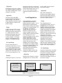
Power Supply
Settings: 5 V
Limit: 3.1 A
+
-
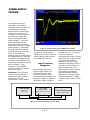
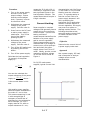
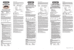
Figure 2. Transient Response for B&K Precision 9130
are ignored, and therefore
results may vary and may not
reflect exactly what is shown
in the following sections.
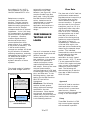
Load Transient
Response
An important element to
power supply testing is a
measurable unit of load
transient response, which
characterizes the capability of
the power supply to stabilize
itself upon a step change in
the load current. In order to
verify the response,
measurements of the rise and
fall times upon a step change
in the load is necessary.
Generally, this type of test
requires a load that is able to
produce a rise and fall time
approximately five times
faster than the power supply.
The following application
demonstrates an effective
approach to testing the load
transient response of a B&K
Precision power supply model
9130.
DC Load
Mode: Transient
Trigger: Pulse 0.1 A to 3.0 A
+
-
Digital Oscilloscope
Trigger: negative slope
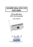
Figure 1. Load Transient Response Test Setup
4 of 17
Objective
Characterize the time it takes
for a power supply to stabilize
its output voltage after a step
change in the load.
transient response is observed
during the rise time in the load
with a step change from 1.5 A
to 3 A. The output voltage
dropped by approximately 1.6
mV.
Approach
Connect a DC load (B&K
Precision 8500 DC load) to a
power supply. Use the DC
load's transient mode to apply
a step change in load to the
power supply.
Setup
A B&K Precision 9130 power
supply was set to 5 V output
with the current limit set to 3
A. A B&K Precision 2542
digital oscilloscope was used
to view the power supply's
output voltage. The scope
was AC coupled and set to
trigger on a negative slope.
DC Load Setup
The DC load was set to
transient mode from 1.5 A to
3 A. Pulse triggering mode
was selected for the DC load,
which means a trigger signal
causes the load to go from 1.5
A to 3 A, then back to 1.5 A.
Load Regulation
Load regulation is another
important element when
testing a power supply. It is a
performance measurement
that requires setting the power
supply to its rated voltage. To
be specific, the test for
measuring this element is
based on measuring the
output voltage levels of the
supply when a load connected
to it changes from zero
current to rated current, which
differs depending on the
model used under testing.
The purpose for this test is to
ensure the accuracy and
capability for a power supply
to maintain its voltage output
level under rated load current
changes. Before testing,
verify that the load used for
the test supports the
maximum rated current and
voltage of the power supply.
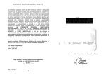
Objective
Results
Looking at Figure 2, the load
DC Load
Mode: CC mode
Current: Rated current of
pow er supply
+
-
Measure the change in output
voltage from no current load
to the rated current load of
the power supply.
Approach
Use a DC voltmeter to
measure the voltage change
when the DC load is used to
step the power supply from 0
current to rated current.
Setup
The measurement is
conceptually simple, but it is
critical that the voltmeter
used to measure the voltage
change is connected to the
output terminals of the power
supply independently of the
leads used to connect to the
DC load. Failure to do this will
measure the contact
resistance of the power leads,
overestimating the load
regulation and output
resistance of the power
supply. Connect the voltmeter
and DC load in parallel to the
power supply's terminals (See
Figure 3 for setup diagram).
DC Load Setup
Press the I-set button (for B&K
Precision 8500) to change the
DC load to constant current
mode (you may have to press
the button twice). Set the
current to the rated current of
the power supply.
Power Supply
Voltmeter
Settings: Rated output V
Current: Max. limit
+
-
Figure 3. Load Regulation Test Setup
5 of 17
+
-
Procedure
1. Turn on the power supply
and set it to its rated
output voltage. Ensure
that the current adjust
knob, if present, is set to
its maximum value.
2. Write down the measured
voltage of the power
supply. Call this value V0.
3. Press I-set on the DC load
to set to power supply's
rated value. Turn on the
input of the load by
pressing On/Off.
4. Write down the measured
voltage of the power
supply. Call this value V.
5. Turn off the DC load's input
by pressing the On-Off
button.
6. Turn off the power supply.
Calculate the load regulation
(in percent) of the power
supply by
100
V0 −V
V0
measuring 30 V with 100 V
resolution is required to have
two significant figures in the
load regulation number. This
measurement would require a
6 digit voltmeter.
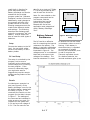
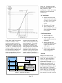
Current Limiting
Power supplies in constant
voltage mode generally have a
preset limit to the maximum
current output. Current limit
testing consists of
measurements that define the
behavior of a power supply
and its current regulation.
These measurements can be
characterized by a voltage vs.
current curve, which portrays
how and when the power
supply enters from CV to CC
mode. Ideally, precise current
regulation reflects a voltage
vs. current curve similar to
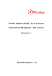
Figure 4.
characteristics look like Figure
4, with small or very minimal
bending near the crossover
point. It is good practice to
test the current limits of a
power supply because it will
aid in protecting the
equipment for its application.
Without a certain degree of
current regulation, the supply
may even over power or
damage certain devices. The
following describes a test
setup for testing current limit
of a B&K Precision 9120A
power supply.
Objective
Determine the current limit of
a power supply under test.
Approach
Use a power supply, DC load,
and a computer to analyze
voltage versus current
characteristics.
For CV/CC mode power
supplies, typical current limit
(1)
You can also calculate the
output resistance of the power
supply as
V 0 −V
where i
i
is the current drawn in this
test.
High quality power supplies
have low output resistances in
the order of 1 m or less.
This means measuring V0 and
V with enough digits is
necessary to avoid loss of
significance in the subtraction.
As an example, for a 30 V
supply rated at 3 A with an
output resistance of 1 m,
Figure 4. Voltage vs. Current Curve
6 of 17
Setup
Connect the power supply in
parallel to the DC load. Set
the power supply to its rated
voltage and set a preset value
for current. The DC load
should display the rated
voltage if power supply's
output is on. Incrementally
increase the current drawn
from the load and observe the
behavior of the voltage in the
power supply. When the
current on the load gets close
to the power supply preset
current limit, observe before,
during, and after the crossover
point, where the power supply
switches from CV to CC mode.
DC Load Setup
Set the DC load to CC mode
by pressing I-set (for B&K
Precision 8500). You have
have to press twice. Turn on
DC load's input.
Results
A B&K Precision 9120A DC
power supply rated at 32 V
and 3 A was tested with a DC
load. The voltage from before
to after the current crossover
point was observed. Table 1
shows the data of some
measurements to demonstrate
the power supply behavior
before and after the crossover
point.
Power supply
measurements
(readings from power supply)
Voltage
Current
Mode
32.0001 V
0.00024 A
CV
31.9999 V
2.65178 A
CV
31.9999 V
2.99467 A
CV
0.1569 V
2.99999 A
CC
Table 1: Measured Data from B&K
Precision 9120A.
It follows that the
measurements demonstrate a
voltage vs. current curve
similar to Figure 4. Drawing
from the data, the voltage
drops immediately upon
reaching the crossover point,
which is at 2.99467 A in this
case. The power supply
changes to CC mode after this
point, and voltage remains at
0.1569 V, with current limited
to 2.99999 A. This behavior is
normal and expected for a CV/
CC power supply. There are
other types of power supplies
with different current limit
designs such as foldback
current and CV power supplies
(without CC mode). The
voltage versus current curve
will greatly differ from that of
CV/CC power supplies, so it is
advised to test their current
limit characteristics before
utilizing them in devices or
applications.
BATTERY TESTING
The forms and standards for
storing, renewing, and using
energy are evolving. New
methods for providing power
7 of 17
for electronic products have
been discovered and are far
more complex than they were
several decades ago. With
increasing need in our society
for clean and efficient energy,
engineers have now turned
their focus to develop
applications that utilize, for
example, fuel cells,
supercapacitors, and
photovoltaic energy. Due to
the complexity in the design of
these sources, it is useful to
have a programmable test
instrument that can verify
precise details of the sources'
behavior. This is often where
a DC load comes in handy
because of its programmable
flexibility as well as its
capability to run discharge
tests on power sources like
batteries. This section will
provide a basic overview that
demonstrate an efficient way
to perform battery discharge
and internal resistance testing.
Battery Discharge
Curves
When designing and testing a
battery for powering a device,
a great deal of attention
reflects on energy efficiency
and lifetime. For this reason,
a standard performance test
consists of analyzing discharge
curves that characterize the
behavior of the battery. By
observing these curves, the
battery life can be measured,
and its efficiency can be
computed. Some DC loads
provide this feature to allow
battery discharge
measurement, in which the
total charge is provided in Ah
(ampere*hour) to a specified
voltage. B&K Precision's 8500
DC load series all provide this
useful built-in function for
quick setup and testing.
Battery discharge can also be
tested with the provided
program under the “Software
Examples” section of this note.
Additionally, small changes to
the program will offer even
greater control for the test,
allowing measurements to be
made under different modes
and settings. The following
describes the discharge test
setup for a consumer “AA” size
battery. Similar setups can
also be used for other types of
batteries.
Setup
Connect the battery to the DC
load. You can either solder
wires to the battery or use a
battery holder.
DC Load Setup
The setup is controlled by the
program, but be sure to
manually set the voltage and
current range prior to running
the test program. If the
current is reasonably large,
you might also want to
suggest they use the remote
voltage sensing feature of the
DC load.
data file is aa_test and “78deg
F” is a string included at the
end of each line of the file.
Note: For more details on the
program commands and to
run the test, find the
instructions and use the
python script provided
towards the end of this
application note categorized
under “Battery Discharge
Test”.
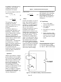
Battery Internal
Resistances
The DC load is an effective
tool for measuring the internal
resistance of a battery. The
battery is typically modeled as
the dashed area in the circuit
illustrated in Figure 8. The
voltage source Vo is considered
ideal and is the open circuit
voltage of the battery. The
internal resistance Ri is used
DC Load
+
+ AA size battery Figure 5. Battery Discharge Test
Setup
to idealize the internal losses
in the battery when current is
flowing. If the battery's
electrochemistry is regarded
as a network of voltage
sources and resistances, then
Vo and Ri comprise the
Thevenin equivalent circuit.
For alkaline batteries, the
internal resistance goes up as
Results
Provided as an example is a
plot (see Figure 6) of the
battery discharge curve for the
AA Alkaline battery tested with
the setup in Figure 5. The
command line used to run the
program for the data is shown
in Figure 7. The settings of
the command are indicated in
order as set to com port 5 in
constant current mode with
0.5 A and a cut off voltage of
0.5 V. The file name for the
Figure 6. AA Alkaline Battery Discharge Curve
8 of 17
-
the battery's chemical energy
is used up. The internal
resistance drops as the
temperature increases.
If VL is the voltage across the
load, we have
V L =Vo iR i
python battery.py 5 cc 0.5 0.5 aa_test 78deg F
Figure 7. Command Used to Run Program
measured as:
Ri =
(2)
V o−V
0.5
(4)
Thus,
R i=
∣V L−Vo∣
i
(3)
This gives us a way to
evaluate the internal
resistance using the DC load,
either manually or by a
program.
For smaller batteries, a
programming approach is an
advantage. Measurements
can be made quickly, causing
less drain on the battery.
Using an oscilloscope, a
millisecond-wide current pulse
can be used to make a useful
internal resistance
measurement. The approach
for measuring a “D” size
battery's internal resistance is
observed in the following.
Note that this is only one of
the practical ways for
measuring internal resistance.
There are other methods not
mentioned here.
Setup
Connect the battery to the DC
load. Use a battery holder or
solder wires to the battery if
necessary. If soldering wires,
do not overheat the battery
due to risk of rupture.
Connect two wires as close to
the battery terminals as
possible and run these to the
remote sense terminals on the
DC load (be sure to observe
the proper polarity). Turn on
load with the configurations
under “DC Load Setup” below.
Make sure the battery voltage
has stabilized and write this
down as the starting voltage
V0. Then trigger the transient
current levels and immediately
watch the displayed voltage.
Within two seconds, make
note of the lowest voltage
displayed and label this as V.
Use equation (4) to calculate
the internal resistance. A
setup diagram is provided in
Figure 9 for the purpose of
illustration.
DC Load Setup
1. Turn on DC Load's
remote sense feature.
2. Set trigger to
immediate.
3. Set load to CC mode at
0.005 A.
4. Setup transient mode
with current levels from
0 A for 0.5 ms to 0.505
A for 2000 ms in pulse
mode.
Results
Using the test setup in Figure
9, the stabilization voltage
(V0) for the measured battery
is 1.496 V. With 0.505 A load,
Approach
Measure the battery's voltage
at two different current loads.
The remote sense capability of
B&K Precision's 8500 DC load
will be used to avoid errors
due to wire resistances. The
test method follows the
recommendation of [1] by
applying a stabilization current
of 5 mA, measuring the
battery's voltage V0, applying
a current of 505 mA, and
measuring the voltage V. The
internal resistance is
Figure 8. Circuit Model of Battery and Internal Resistance
9 of 17
the voltage (V) is 1.415 V.
Using equation (4) gives an
internal resistance of 0.16 Ω.
Batteries are complex
nonlinear electrochemical
devices. The two common
electrical measurements of
batteries used to gauge their
state are the DC internal
resistance and the AC internal
impedance. In the "old" days,
AC characteristics of a battery
were not terribly important for
DC operation. However,
modern digital electronic
devices can draw sharp
current spikes from their
power source (e.g., switching
a cell phone to transmit). In a
1 kW car audio system,
currents can exceed 100 A and
the AC behavior of batteries,
stiffening capacitors, and stray
inductances can all play a role.
DC loads can be useful in
helping investigate the
dynamic behavior of these
systems.
The simple model of a battery
as an ideal voltage source in
Remote sense
+ DC Load
Setting: Immediate Trigger
Mode: CC at 0.005A
Transient: Pulse 0 to 0.505A
+
-
+ D size battery -
series with a resistance
captures the first order
behavior (see Figure 8). More
complex models have also
been used. Using DC loads
like B&K Precision's 8500
series, batteries can be
characterized in a manner
which will mirror their
application and construct a
model appropriate for the
design.
PERFORMANCE
TESTING OF DC
LOADS
Just as it is important to have
a good power supply that will
perform accurate
measurements under various
test conditions, it is essential
to have a DC load that is
robust and perform under
required specifications and
test setups. Some of the most
common tests used for
verifying features of a DC load
include trigger delay, switching
time, and slew rate. In the
following section, slew rate
testing for the B&K Precision
8510 DC load will be
highlighted.
Disclaimer: The following
sections include general
setups with some settings
specified for the test
environment. Some details
are ignored, and therefore
results may vary and may not
reflect exactly what is shown
in the following sections.
Slew Rate
The slew rate of a DC load is a
performance measurement
that determines how quickly a
DC load can draw current
within different ranges of
current transition. In general,
the slew rate for low current
transitions, say 0 to 0.5 A, is
significantly lower than slew
rate for current transitions
from 30 to 70 A. Generally,
the appropriate way to test
slew rate is to observe a
portion of the timing during
maximum current transition.
The graph in Figure 10
illustrates this. Between the
10% and 90% region, the
slew rate can be measured by
observing the steepest slope
portion. The indicated
measured time would be used
to calculate the slew rate.
Hence, the slew rate
calculation is simply (rated
max. current – 0 A) / T, where
T is the measured time from
10% to 90% region and rated
max. current is the specified
maximum current of each
load. The following will
demonstrate how to test the
slew rate of B&K Precision's
8510 DC Load.
Approach
Set the DC load to transient
mode and allow it to draw
current from 0 to maximum
rated current. Observe
current transition changes and
timing on an oscilloscope.
Setup
Three B&K Precision's 1796
high current power supplies
are connected in parallel.
Figure 9. Test Setup For Battery
Internal Resistance
10 of 17
Figure 11. Connect the BNC
to binding post adapter into a
B&K Precision's 2542
oscilloscope. Follow the setup
below for the DC load and
oscilloscope.
DC Load Setup
1. Setup transient mode
with current levels from
0 A for 0.5 ms to 120 A
for 1000 ms in pulse
mode.
2. Set load to CC mode
3. Turn on input for a
short moment. Turn off
once oscilloscope setup
is complete.
Oscilloscope Setup
1. Set to single run.
Figure 10. Slew Rate Measurement Graph
Since each supply can output
maximum of 50 A, it can
produce enough current for
B&K Precision's 8510 DC load
to draw at its maximum range
(0-120 A). A handful of shunt
resistors rated at 5 W 0.22 ΩJ
are connected in parallel and
are connected to a BNC-tobinding post adapter. A larger
shunt can also be used to
simplify the same setup and
reduce the temperature from
heat dissipation. Since high
current will be drawn, it is
important to note here that
heavy gauge wires should be
used to connect the power
supplies to each other and to
the load. Connect the power
supply to the DC load and
shunt resistors as illustrated in
Oscilloscope
Power supply
+
-
Mode: Single Trigger
Power supply
+
-
Power supply
+
-
DC Load
Shunt
Resistance
Mode: CC
Transient: 0 A to 120 A
+
-
Figure 11. Slew Rate Test Setup
11 of 17
2. Adjust trigger level
until waveform trace is
captured.
3. Adjust vertical and
horizontal scale and the
trigger level and run
once again.
4. Repeat steps 2 and 3
until a good sampled
trace is captured.
Results
Observe the trace on the
oscilloscope and compare it to
Figure 10. Use the scope's
cursors to approximate the
10% and 90 % mark.
Observe the steepest slope in
between the cursor lines. A
rough estimate can be made
by taking the difference of the
two cursor lines. Since this
setup tests a current transition
from 0 A to 120 A, slew rate
can be calculated by dividing
the change in current over the
change in time; that is the
difference of the cursors. For
B&K Precision's 8510 DC load,
slew rate is measured to be 1
A/μs.
OTHER DC LOAD
APPLICATIONS
rates of B&K Precision's 8500
DC load. This load can
measure with a millivolt
resolution before indicating an
overrange. Refer to the
section for detailed
information on setting up and
running the software
application.
Fuse
DC loads can be very
resourceful for various tests
and applications. Sometimes,
they may even act as a
different type of test
instrument for measurement.
A good example would be a
voltmeter. Other practical
applications that will be
mentioned in this section is a
fuse. DC loads can also act as
a fuse in a circuit for
monitoring current thresholds
to help prevent possible
damage from overcurrent or
overpower.
Voltmeter
In any design or test
environment, a voltmeter is
required in one way or another
for measurements. It is one
of the most useful test tool
today. For this reason, it is
often convenient to have a DC
load that can read voltages
when a voltmeter is not
around. For simplicity, a test
program script has been
provided under “Software
Examples” at the end of the
note under section labeled
“Voltmeter Reading” to
perform simple voltage
measurements and reading
The application described in
this section is to demonstrate
how to use a DC load as a fuse
in a circuit. Under program
control, the load can shut off
when either current, voltage,
or power measured exceeds a
set value in the load. This is a
basic application for a fuse,
and due to some delays from
the software control, it is not
recommended for use if fast
responses are required. The
program codes to run this
application can be found in the
“Software Examples” section
under “Fuse Application”.
Details of usage and operation
are provided in the same
section.
Setup
Connect load in series with a
circuit. Be sure that remote
sense is off. Run the program
to monitor current. Threshold
value is set in the program.
Note: The DC load does not
behave like a pure resistance.
For this fuse application, it
may be hard to test low
currents in the few mA range.
For B&K Precision's 8500 load,
there is a turn-on threshold
voltage of around 0.1 volts
before the load starts
12 of 17
conducting current and, thus,
it may jump past a low
current setting. Thus, please
test this fuse application
carefully before using it to
protect valuable circuitry.
SOFTWARE
EXAMPLES
The following sections include
the source codes for all
software based applications
and examples previously
mentioned. If not done
already, please read the
documentation provided from
B&K Precision's website at:
http://www.bkprecision.com/p
roducts/categories/sub_catego
ries/models/?
model=8500#software for
successful installation of the
python libraries. This must
be setup correctly prior to
using any of the source codes
provided in this note. Be sure
to also read the instructions
under each software examples
for correct usage.
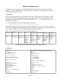
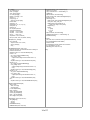
Battery Discharge Test
The objective of this program is to characterize the discharge curves of common household
batteries. It can be used to monitor and log data when a battery is discharged by one of B&K
Precision's 8500 series DC loads.
Instructions
There are two settings that can be modified in the code to cater particular test settings. These
two settings are the interval between each reading, defined as “interval_s” in beginning of the
program, and baudrate, defined as “baudrate” at the end of main(). By default, interval_s = 1
and baudrate = 38400.
To run the command, lets use the example given previously.
python battery.py 5 cc 0.5 0.5 aa_test 78deg F
The above command is in a specific order, which is read as port 5, CC mode, 0.5 A in CC mode,
0.5 V cut off voltage, filename to save data as “aa_test.dat”, and extra strings added at the end of
each record is “78deg F”. Refer to Table 2 below for detailed instructions.
Note: The program will NOT overwrite any existing data files.
Run command
Python file
name
Port #
Mode:
python
Name of the
COM port #
cc: constant
python program used to connect current
to PC
cv: constant
voltage
cp: constant
power
cr: constant
resistance
Decimal value
for constant
mode
Cut off voltage
Filename of
recorded data
Any string to
attach at end of
each line
Any value set
for the
respective
mode. (i.e. 0.5
in cc mode is
0.5 A, 2 in cv
mode is 2 V)
Decimal value
of cut off
voltage to end
program
Files are saved
in same folder
as the python
program file
with .dat
extension
Any strings of
text can be
added for
reference
Table 2. Instructions on Command for Battery Discharge Test Script
battery.py
Data file:
Header info:
# Command line
# Date and time for start of test
Entry info:
time voltage current power
import sys, dcload
from win32com.client import Dispatch
from string import join
from time import time, sleep
from msvcrt import kbhit, getch
out = sys.stdout.write
nl = "\n"
interval_s = 1 # Interval between readings
msg = '''Usage: %(name)s port mode value cov filename [docstring]
Test a battery with a DC load until the specified cut-off voltage is reached.
Arguments are:
port
COM port that the load is at.
mode
cc for constant current
cv for constant voltage
cp for constant power
cr for constant resistance
value
Decimal value of desired constant mode value.
cov
Cut-off voltage in volts.
filename
Data will be stored in filename.dat.
docstring
Any further text is just logged to the data file.
''' % locals()
print msg
exit(1)
def Usage():
name = sys.argv[0]
def ProcessCommandLine():
if len(sys.argv) < 6:
time is in seconds since start of test
Other measurements are in V, A, and W
We talk to a DC load using COM.
'''
13 of 17
Usage()
port = int(sys.argv[1])
mode = sys.argv[2]
value = float(sys.argv[3])
cov = float(sys.argv[4])
filename = sys.argv[5] + ".dat"
docstring = ""
if len(sys.argv) > 6:
docstring = join(sys.argv[6:])
# Check values
assert(port >= 0)
assert(mode in ("cc", "cv", "cp", "cr"))
assert(value > 0)
assert(cov > 0)
from os.path import exists
assert(not exists(filename))
out("Mode = %s\n" % mode)
out("Value = %s\n" % value)
out("cov = %s\n" % cov)
out("filename = %s\n" % filename)
return port, mode, value, cov, filename, docstring
def Set(task, error_message):
if error_message:
out("Error on task '%s':\n" % task)
out(error_message)
exit(1)
def SetModeAndValue(load, mode, value):
# Set mode and value. Also check that the maximum setting is at
# least the value we want.
Set("Set to mode %s" % mode, load.SetMode(mode))
if mode == "cc":
max_current = float(load.GetMaxCurrent())
if max_current < value:
out("Max current setting is less than desired value" + nl)
exit(1)
Set("Set to value %g" % value, load.SetCCCurrent(value))
elif mode == "cv":
max_voltage = float(load.GetMaxVoltage())
if max_voltage < value:
out("Max voltage setting is less than desired value" + nl)
exit(1)
Set("Set to value %g" % value, load.SetCVVoltage(value))
elif mode == "cp":
max_power = float(load.GetMaxPower())
if max_power < value:
out("Max power setting is less than desired value" + nl)
exit(1)
Set("Set to value %g" % value, load.SetCWPower(value))
else:
Set("Set to value %g" % value, load.SetCRResistance(value))
log("# Command line: %s\n" % join(sys.argv[1:]))
'log("# %s\n" % version)'
msg = "# Test start time = " + load.TimeNow() + nl
LogMsg(msg)
Set("Turn load on", load.TurnLoadOn())
voltage, current, power = GetCurrentVoltagePower(load)
start_time = time()
while voltage >= cov:
voltage, current, power = GetCurrentVoltagePower(load)
current_time = time() - start_time
LogMsg("%9.2f %9.4f %8.4f %9.4f\n" % \
(current_time, voltage, current, power))
sleep(interval_s)
if kbhit():
c = getch()
if c == "Q":
break
Set("Turn load off", load.TurnLoadOff())
LogMsg("# Test finish time = " + load.TimeNow() + nl)
load.SetLocalControl()
def main():
port, mode, value, cov, filename, docstring = ProcessCommandLine()
load = Dispatch('BKServers.DCLoad85xx')
baudrate = 38400
load.Initialize(port, baudrate) # Open a serial connection
log = open(filename, "w").write
RunTest(log, load, mode, value, cov)
main()
def GetCurrentVoltagePower(load):
def get_value(f):
value, unit = f.split()
return float(value)
s = load.GetInputValues()
fields = s.split("\t")
voltage = get_value(fields[0])
current = get_value(fields[1])
power = get_value(fields[2])
return voltage, current, power
def RunTest(log, load, mode, value, cov):
def LogMsg(msg):
out(msg)
log(msg)
load.SetRemoteControl()
SetModeAndValue(load, mode, value)
14 of 17
Voltmeter Reading
In this section, the codes provided below are used for the “voltmeter” application using the DC
load. It provides a convenient and remote way to collect voltage readings into a data file to serve
its purpose.
Instructions
Two settings must be configured correctly to run the script. They are port and baudrate. In the
code of voltmeter.py, they are declared at the beginning as “port = 5” and “baudrate = 38400” by
default. Please change the values to match the port and baudrate settings used to interface on
the PC. Note: The DC load must have the same baudrate configurations as in the code, and port
number has to match the COM port on the PC used to connect to DC load.
voltmeter.py
import sys, dcload
from time import time
from win32com.client import Dispatch
from msvcrt import kbhit
port = 5
baudrate = 38400
load = Dispatch('BKServers.DCLoad85xx')
load.Initialize(port, baudrate) # Open a serial connection
load.SetRemoteControl()
of = open("fast.dat", "w")
start = time()
count = 1
while True:
msg = "%6d %8.2f s %s\n" % (count, time() - start, load.GetInputValues())
of.write(msg)
if kbhit():
break
count += 1
finish = time() - start
load.SetLocalControl()
of.write("\nReading rate = %.1f readings/second\n" % (count/finish))
print "\nReading rate = %.1f readings/second\n" % (count/finish)
Fuse Application
A practical feature in most DC loads is the overpower, overcurrent, and overvoltage protection.
With this, a DC load can behave like a fuse in a circuit, monitoring current, voltage, or power from
exceeding design specifications of the circuit. An excellent way to demonstrate this application is
to use a program. Provided in the following is an example python script for monitoring current
using B&K Precision's 8500 DC load.
Instructions
Two settings must be configured correctly to run the script. They are port and baudrate. In the
code of voltmeter.py, they are declared at the beginning as “port = 5” and “baudrate = 38400” by
15 of 17
default. Please change the values to match the port and baudrate settings used to interface on
the PC.
Here's an example to run the command:
python fuse.py 5
The value “5” represents the fuse value to set. In this example, it is 5 A. With slight
modifications to the script, the program can also monitor voltage and power.
fuse.py
import sys, dcload
from time import time
from win32com.client import Dispatch
from msvcrt import kbhit
port = 5
baudrate = 38400
def ReadCurrent(load):
fields = load.GetInputValues().split("\t") # Split on tab characters
current = float(fields[0].split()[0]) # Remove the "A"
return current
def main():
# Check the command line
if len(sys.argv) != 2:
print "Usage: %s fuse_value_in_A" % sys.argv[0]
exit(1)
# Get the desired fuse value from the command line
fuse_value_A = float(sys.argv[1])
assert(fuse_value_A) > 0
# Establish a load connection
load = Dispatch('BKServers.DCLoad85xx')
load.Initialize(port, baudrate) # Open a serial connection
load.SetRemoteControl()
load.SetMode("cc") # Set to constant current mode
load.SetCCCurrent(fuse_value_A) # We won't exceed this value
load.TurnLoadOn()
current = ReadCurrent(load)
while current < fuse_value_A:
if kbhit(): break
current = ReadCurrent(load)
load.TurnLoadOff()
load.SetLocalControl()
main()
Reference
[1]
http://data.energizer.com/PDFs/BatteryIR.pdf A technical bulletin on internal resistance.
16 of 17
© 2009 B&K Precision Corp.
17 of 17