1
SPLIT-TYPE, HEAT PUMP AIR CONDITIONERS
SPLIT-TYPE, AIR CONDITIONERS
December 2010
No. OCH492
SERVICE MANUAL
Indoor unit
[Model names]
[Service Ref.]
PCA-RP71HAQ
PCA-RP125HAQ
PCA-RP71HAQ
PCA-RP125HAQ
Note:
• This manual describes only
service data of the indoor units.
• RoHS compliant products have
<G> mark on the spec name
plate.
• For servicing of RoHS compliant products, refer to the
RoHS Parts List.
CONTENTS
INDOOR UNIT
Model name
indication
1. REFERENCE MANUAL................................... 2
2. SAFETY PRECAUTION................................... 3
3. PART NAMES AND FUNCTIONS....................7
4. SPECIFICATIONS............................................ 9
5. NOISE CRITERION CURVES........................ 10
6. OUTLINES AND DIMENSIONS......................11
7. WIRING DIAGRAM............................................. 13
8. REFRIGERANT SYSTEM DIAGRAM............. 14
9. TROUBLESHOOTING....................................15
10. SPECIAL FUNCTION..................................... 26
11. DISASSEMBLY PROCEDURE.......................29
PARTS CATALOG (OCB492)
TEMP.
ON/OFF
REMOTE CONTROLLER
(Option)
1
REFERENCE MANUAL
1-1. OUTDOOR UNIT’S SERVICE MANUAL
Service Ref.
Service Manual No.
PUHZ-RP71VHA4
PUHZ-RP125/140VKA
PUHZ-RP125/140/250YKA
OCH451
OCB451
PU(H)-P71VHAR3.UK
PU(H)-P71/125/140YHAR3.UK
OC379
PUHZ-P125/140VHA3R2.UK
PUHZ-P125/140YHAR1.UK
OCH415 / OCB415
PUHZ-P250YHA3R2
OCH424 / OCB424
1-2. TECHNICAL DATA BOOK
Series (Outdoor unit)
Manual No.
PUHZ-RP • HA4
PUHZ-RP • KA
OCS16
PUHZ-P • VHA3
PUHZ-P • YHAR3
OCS17
Note:
The phrase “Wired remote controller” in this service manual refers only to the PAR-21MAA.
If you need any information for the PAR-30MAA, please refer to the instruction book included in PAR-30MAA box.
2
2
SAFETY PRECAUTION
2-1. ALWAYS OBSERVE FOR SAFETY
Before obtaining access to terminal, all supply
circuits must be disconnected.
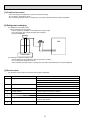
2-2. CAUTIONS RELATED TO NEW REFRIGERANT
Cautions for units utilising refrigerant R407C
Do not use the existing refrigerant piping.
Use liquid refrigerant to charge the system.
The old refrigerant and lubricant in the existing piping
contains a large amount of chlorine which may cause the
lubricant deterioration of the new unit.
If gas refrigerant is used to seal the system, the composition
of the refrigerant in the cylinder will change and performance
may drop.
Use “low residual oil piping”
Do not use a refrigerant other than R407C.
If there is a large amount of residual oil (hydraulic oil, etc.)
inside the piping and joints, deterioration of the lubricant
will result.
If another refrigerant (R22, etc.) is used, the chlorine in the
refrigerant may cause the lubricant deterioration.
Use a vacuum pump with a reverse flow check valve.
Store the piping to be used indoors during
installation, and keep both ends of the piping
sealed until just before brazing. (Leave elbow
joints, etc. in their packaging.)
The vacuum pump oil may flow back into the refrigerant
cycle and cause the lubricant deterioration.
Ventilate the room if refrigerant leaks during
operation. If refrigerant comes into contact with
a flame, poisonous gases will be released.
If dust, dirt, or water enters the refrigerant cycle,
deterioration of the oil and compressor trouble may result.
The refrigerant oil applied to flare and flange
connections must be ester oil, ether oil or
alkylbenzene oil in a small amount.
If large amount of mineral oil enter, that can cause
deterioration of refrigerant oil etc.
3
[1] Cautions for service
· After recovering the all refrigerant in the unit, proceed to working.
· Do not release refrigerant in the air.
· After completing the repair service, recharge the cycle with the specified amount of liquid refrigerant.
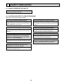
[2] Refrigerant recharging
(1) Refrigerant recharging process
1Direct charging from the cylinder.
· R407C cylinder are available on the market has a syphon pipe.
· Leave the syphon pipe cylinder standing and recharge it.
(By liquid refrigerant)
Unit
Gravimeter
(2) Recharge in refrigerant leakage case
· After recovering the all refrigerant in the unit, proceed to working.
· Do not release the refrigerant in the air.
· After completing the repair service, recharge the cycle with the specified amount of liquid refrigerant.
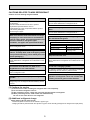
[3] Service tools
Use the below service tools as exclusive tools for R407C refrigerant.
No.
1
Tool name
Gauge manifold
Specifications
· Only for R407C
· Use the existing fitting SPECIFICATIONS. (UNF7/16)
· Use high-tension side pressure of 3.43MPa·G or over.
2
Charge hose
· Only for R407C
· Use pressure performance of 5.10MPa·G or over.
3
Electronic scale
4
Gas leak detector
· Use the detector for R134a or R407C.
5
Adaptor for reverse flow check
· Attach on vacuum pump.
6
Refrigerant charge base
7
Refrigerant cylinder
—
—
· For R407C
· Top of cylinder (Brown)
· Cylinder with syphon
8
Refrigerant recovery equipment
—
4
CAUTIONS RELATED TO NEW REFRIGERANT
Cautions for units utilising refrigerant R410A
Use new refrigerant pipes.
Do not use refrigerant other than R410A.
In case of using the existing pipes for R22, be careful with
the followings.
· For RP71VHA3 and RP125 be sure to perform
replacement operation before test run.
· Change flare nut to the one provided with this product.
Use a newly flared pipe.
· Avoid using thin pipes.
If other refrigerant (R22 etc.) is used, chlorine in refrigerant can cause deterioration of refrigerant oil etc.
Use a vacuum pump with a reverse flow check
valve.
Vacuum pump oil may flow back into refrigerant cycle and
that can cause deterioration of refrigerant oil etc.
Make sure that the inside and outside of refrigerant piping is clean and it has no contaminants
such as sulfur, oxides, dirt, shaving particles, etc,
which are hazards to refrigerant cycle.
In addition, use pipes with specified thickness.
Contamination inside refrigerant piping can cause deterioration of refrigerant oil etc.
Use the following tools specifically designed for
use with R410A refrigerant.
The following tools are necessary to use R410A refrigerant.
Gauge manifold
Charge hose
Gas leak detector
Torque wrench
Tools for R410A
Flare tool
Size adjustment gauge
Vacuum pump adaptor
Electronic refrigerant
charging scale
Store the piping to be used during installation
indoors, and keep both ends of the piping sealed
until just before brazing. (Leave elbow joints, etc.
in their packaging.)
Keep the tools with care.
If dirt, dust or moisture enter into refrigerant cycle, that can
cause deterioration of refrigerant oil or malfunction of compressor.
If dirt, dust or moisture enter into refrigerant cycle, that can
cause deterioration of refrigerant oil or malfunction of compressor.
The refrigerant oil applied to flare and flange
connections must be ester oil, ether oil or
alkylbenzene oil in a small amount.
Do not use a charging cylinder.
If large amount of mineral oil enter, that can cause deterioration of refrigerant oil etc.
If a charging cylinder is used, the composition of refrigerant will change and the efficiency will be lowered.
Ventilate the room if refrigerant leaks during
operation. If refrigerant comes into contact with
a flame, poisonous gases will be released.
Charge refrigerant from liquid phase of gas
cylinder.
If the refrigerant is charged from gas phase, composition
change may occur in refrigerant and the efficiency will be
lowered.
[1] Cautions for service
(1) Perform service after collecting the refrigerant left in unit completely.
(2) Do not release refrigerant in the air.
(3) After completing service, charge the cycle with specified amount of refrigerant.
(4) When performing service, install a filter drier simultaneously.
Be sure to use a filter drier for new refrigerant.
[2] Additional refrigerant charge
When charging directly from cylinder
· Check that cylinder for R410A on the market is syphon type.
· Charging should be performed with the cylinder of syphon stood vertically. (Refrigerant is charged from liquid phase.)
5
Unit
Gravimeter
[3] Service tools
Use the below service tools as exclusive tools for R410A refrigerant.
No.
1
Tool name
Gauge manifold
Specifications
· Only for R410A
· Use the existing fitting specifications. (UNF1/2)
· Use high-tension side pressure of 5.3MPa·G or over.
2
Charge hose
· Only for R410A
· Use pressure performance of 5.09MPa·G or over.
3
Electronic scale
4
Gas leak detector
· Use the detector for R134a, R407C or R410A.
5
Adaptor for reverse flow check
· Attach on vacuum pump.
6
Refrigerant charge base
7
Refrigerant cylinder
—
—
· Only for R410A
· Top of cylinder (Pink)
· Cylinder with syphon
8
Refrigerant recovery equipment
—
6
3
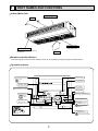
PART NAMES AND FUNCTIONS
Indoor (Main) Unit
Left/right guide vanes
Change the direction of airflow
from the horizontal blower.
Air outlet
Oil filter (Air intake)
+ It prevents oil from
getting into the unit.
Up/down guide vanes
Change the direction of airflow from the
vartical blower.
Air intake
Remote controller (Option)
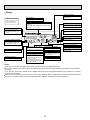
Once the controls are set, the same operation mode can be repeated by simply pressing the ON/OFF button.
Operation buttons
ON/OFF button
Set Temperature buttons
Down
Fan Speed button
Up
Timer Menu button
(Monitor/Set button)
Filter
button
(<Enter> button)
Mode button (Return button)
TEMP.
ON/OFF
Set Time buttons
Check button (Clear button)
Back
Ahead
Timer On/Off button
(Set Day button)
Test Run button
MENU
BACK
PAR-21MAA
MONITOR/SET
ON/OFF
FILTER
DAY
CLOCK
CHECK TEST
OPERATION
Airflow Up/Down button
CLEAR
Louver button
(
Operation button)
To preceding operation
number.
Opening the
cover.
Ventilation button
Operation button)
(
To next operation number.
7
Display
“Sensor” indication
For purposes of this explanation,
all parts of the display are shown.
During actual operation, only
the relevant items will be lit.
Displays when the remote controller
sensor is used.
Day-of-Week
Shows the current day of the week.
Time/Timer Display
“Locked” indicator
Shows the current time, unless the simple or Auto Off
timer is set.
If the simple or Auto Off timer is set, shows the time
remaining.
Indicates that remote controller buttons have been locked.
Identifies the current operation
“Clean The Filter” indicator
Shows the operating mode, etc.
* Multilanguage display is supported.
Comes on when it is time to clean the
filter.
TIME SUN MON TUE WED THU FRI SAT
TIMER
Hr
ON
AFTER
“Centrally Controlled” indicator
Indicates that operation of the remote controller has been prohibited by a master controller.
Timer indicators
AFTER OFF
ERROR CODE
FUNCTION
FILTER
°F°C
°F°C
The indicator comes on if the corresponding timer is set.
WEEKLY
SIMPLE
AUTO OFF
ONLY1Hr.
Fan Speed indicator
Shows the selected fan speed.
“Timer Is Off” indicator
Indicates that the timer is off.
Temperature Setting
Shows the target temperature.
Up/Down Air Direction indicator
Room Temperature display
Shows the room temperature.
The indicator
shows the direction of the outcoming airflow.
Louver display
“One Hour Only” indicator
Indicates the action of the swing
louver. Does not appear if the
louver is stationary.
Displays if the airflow is set to
low and downward during COOL
or DRY mode. (Operation varies
according to model.)
The indicator goes off after one
hour, at which time the airflow direction also changes.
Ventilation indicator
Appears when the unit is running in
Ventilation mode.
(Power On indicator)
Indicates that the power is on.
Caution
Only the Power on indicator lights when the unit is stopped and power supplied to the unit.
If you press a button for a feature that is not installed at the indoor unit, the remote controller will display the “Not Available”
message.
If you are using the remote controller to drive multiple indoor units, this message will appear only if the feature is not present
at every unit connected.
When power is turned ON for the first time, it is normal that “PLEASE WAIT” is displayed on the room temperature indication
(For max. 2 minutes). Please wait until this “PLEASE WAIT” indication disappear then start the operation.
8
INDOOR UNIT
INDOOR UNIT
4
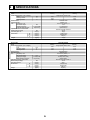
SPECIFICATIONS
Service Ref.
Mode
Power supply(phase, cycle, voltage)
Input
Running current
Starting current
External finish
Heat exchanger
Fan
Fan(drive) × No.
Fan motor output
Airflow(Low-High)
External static pressure
Operation control & Thermostat
Noise level(Low-High)
Unit drain pipe I.D.
Dimensions
W
D
H
Weight
PCA-RP71HAQ
Cooling
Heating
Single phase, 50Hz, 230V
kW
A
A
0.09
0.43
0.86
0.09
0.43
0.86
Stainless steel
Plate fin coil
Sirocco fan (direct) × 2
0.04
17-19(600-670)
0(direct blow)
Remote controller & built-in
34-38
26(1)
1,136(44-3/4)
650(25-5/8)
280(11)
41(90)
kW
*/min(CFM)
Pa(mmAq)
dB
mm(in.)
mm(in.)
mm(in.)
mm(in.)
kg(lbs)
PCA-RP125HAQ
Cooling
Heating
Single phase, 50Hz, 230V
0.26
1.19
2.38
kW
A
A
0.26
1.19
2.38
Stainless steel
Plate fin coil
Sirocco fan (direct) × 4
0.08 + 0.08
30-38(1,060-1,350)
0(direct blow)
Remote controller & built-in
44-50
26(1)
1,520(59-7/8)
650(25-5/8)
280(11)
56(124)
kW
*/min(CFM)
Pa(mmAq)
dB
mm(in.)
mm(in.)
mm(in.)
mm(in.)
kg(lbs)
9
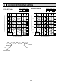
5
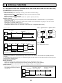
NOISE CRITERION CURVES
NOTCH SPL(dB)
High
38
Low
34
LINE
PCA-RP125HAQ
90
90
80
80
70
NC-70
60
NC-60
50
NC-50
40
NC-40
30
NC-30
20
10
OCTAVE BAND SOUND PRESSURE LEVEL, dB ( 0dB = 0.0002 μbar )
OCTAVE BAND SOUND PRESSURE LEVEL, dB ( 0dB = 0.0002 μbar )
PCA-RP71HAQ
125
250
500
1000
2000
4000
8000
50
NC-50
40
NC-40
30
NC-30
APPROXIMATE
THRESHOLD OF
HEARING FOR
CONTINUOUS
NOISE
63
125
NC-20
250
500
1000
2000
BAND CENTER FREQUENCIES, Hz
ceiling
1m
about 1.4m
NC-70
NC-60
10
63
unit
MICROPHONE
10
LINE
60
NC-20
BAND CENTER FREQUENCIES, Hz
1m
70
20
APPROXIMATE
THRESHOLD OF
HEARING FOR
CONTINUOUS
NOISE
NOTCH SPL(dB)
High
50
Low
44
4000
8000
1098
1136
986 <Air
outlet>
75
<liquid>
175
21
110
75
80
70
Filter element for the exchange
model:PAC-SG38KF-E (12pcs.)
360
handle
3
or more
100
<Flexible hose(accessory)>
650
289
<Suspension bolt pitch>
320
495
<Filter contour dimension>
Filter (3-pieces)
Inspection port
(pipe sensor)
<Air outlet>
Suspension bolt
243
<gas>
1
43
1
Rear wall
Adjustable part
85
45
1136
Ceiling
176
105
140
18
318
2
4
or more
100
366
6
7
Terminal block box
:2
22
0
:20
9
130
250
Less than
Allowing clearances
480
(122 )
8
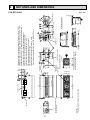
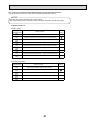
Refrigerant-pipe connection(gas pipe side/flared connection : 5/8F)
Refrigerant-pipe connection(liquid pipe side/flared connection : 3/8F)
Flexible hose(accessory) → Drainage pipe connection(26mm I.D.)
Knockout hole for behind refrigerant-piping arrangement
Knockout hole for upper refrigerant-pipe arrangement
Knockout hole for wiring arrangement : 2- : 27
Terminal block(indoor/outdoor connecting line)
Terminal block(remote controller)
Knockout hole (duct for fresh air intake): 2- : 200
Option parts:duct flange(: 200), model: PAC-SF28OF-E(1 pc.)
75
1224
<Suspension bolt pitch>
<Air intake>
1180
NOTES.
1.Use M10 or W3/8 screw for anchor bolt.
The bottom half of FAN CASING
can be separated.
Electrical box
15
102
110
258
254
295
197
<Air intake>
70~90
13
130
650
280
16
288
120
165
90
Less than
210
38
5
300
2
Less than
Terminal block box
500
90°
2~3
11
or more
PCA-RP71HAQ
(Gap to ceiling)
6
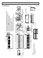
OUTLINES AND DIMENSIONS
Unit : mm
NOTES.
1. Use M10 or W3/8 screw for anchor bolt.
2. Use the current nuts meeting the pipe size
of the outdoor unit.
The bottom half of FAN CASING
can be separated.
<Air intake>
1482
1520
1370 <Air
outlet>
GAS SIDE
LIQUID SIDE
<gas>
<liquid>
80
70
360
: 19.05
: 15.88
: 9.52
RP125
or more
1
18
45
85
140
2
4
Rear wall
298
176
105
Adjustable part
3
: Initial flare nut size
Filter element for the exchange
model:PAC-SG38KF-E (12pcs.)
handle
100
<Flexible hose(accessory)>
650
289
<Suspension bolt pitch>
320
495
<Filter contour dimension>
Filter (4-pieces)
Inspection port
(pipe sensor)
243
21
Available pipe size
75
75
43
197
Suspension bolt
254
295
110
102
110
<Suspension bolt pitch>
75
1564
165
175
<Air outlet>
<Air intake>
70~90
13
120
90
1608
1520
Ceiling
650
280
16
288
210
38
1
Less than
246
6
440
(122)
7
440
or more
100
9
250
:2
22
0
:20
Less than
Allowing clearances
Terminal block box
8
130
Refrigerant-pipe connection(gas pipe side/flared connection : 5/8F, 3/4F)
Refrigerant-pipe connection(liquid pipe side/flared connection : 3/8F)
Flexible hose(accessory) Drainage pipe connection(26mm I.D.)
Knockout hole for behind refrigerant-piping arrangement
Knockout hole for upper refrigerant-pipe arrangement
Knockout hole for wiring arrangement : 2- : 27
Terminal block(indoor/outdoor connecting line)
Terminal block(remote controller)
Knockout hole (duct for fresh air intake) : 2- : 200
Option parts:duct flange(: 200), model: PAC-SF28OF-E(1 pc.)
300
Electrical box
15
Less than
130
(Gap to ceiling)
5
500
2
90°
2~3
Terminal block box
or more
12
258
PCA-RP125HAQ
Unit : mm
7
WIRING DIAGRAM
PCA-RP71HAQ
PCA-RP125HAQ
[LEGEND]
SYMBOL
P. B
I. B
FUSE
CN2L
CN32
CN41
CN51
LED1
LED2
LED3
X1
X4
X5
X6
SW1
SW2
NAME
INDOOR POWER BOARD
INDOOR CONTROLLER BOARD
FUSE (T6.3AL250V)
CONNECTOR (LOSSNAY)
CONNECTOR (REMOTE SWITCH)
CONNECTOR (HA TERMINAL-A)
CONNECTOR (CENTRALLY CONTROLL)
POWER SUPPLY (I. B)
POWER SUPPLY (R. B)
TRANSMISSION (INDOOR-OUTDOOR)
RELAY (DEW PREVENTION HEATER)
RELAY (FAN MOTOR)
RELAY (FAN MOTOR)
RELAY (FAN MOTOR)
SWITCH (MODEL SELECTION) +See Table 1.
SWITCH (CAPACITY CODE) +See Table 2.
SYMBOL
MF1, MF2
C1, C2
H2
TB2
NAME
FAN MOTOR
CAPACITOR (FAN MOTOR)
DEW PREVENTION HEATER
TERMINAL BLOCK (INDOOR UNIT
POWER (OPTION PARTS))
TB4
TERMINAL BLOCK (INDOOR/OUTDOOR
TB5,TB6
CONNECTING LINE)
TERMINAL BLOCK (REMOTE CONTROLLER
Check code
P1
P2
P6
P8
P9
E0 - E5
E6 - EF
TRANSMISSION LINE)
ROOM TEMP.THERMISTOR
(0°C/15kΩ, 25°C/5.4kΩ DETECT)
TH1
Fb
U* , F*
TH2
PIPE TEMP.THERMISTOR/LIQUID
(0°C/15kΩ, 25°C/5.4kΩ DETECT)
TH5
COND./ EVA.TEMP.THERMISTOR
(0°C/15kΩ, 25°C/5.4kΩ DETECT)
R. B
WIRED REMOTE CONTROLLER BOARD
---FFFF
Symptom
Abnormality of room temperature thermistor (TH1)
Abnormality of pipe temperature thermistor/Liquid (TH2)
Freezing/overheating protection is working.
Abnormality of pipe temperature
Abnormality of pipe temperature thermistor/Cond.Eva. (TH5)
Abnormality of the signal transmission between remote
controller and indoor unit
Abnormality of the signal transmission between indoor unit
and outdoor unit
Abnormality of indoor controller board
Abnormality in outdoor unit. Refer to outdoor unit wiring diagram.
No trouble generated in the past.
No corresponding unit
SWITCH (EMERGENCY OPERATION)
MF1
M
CNSK
(RED)
H2
SW2
SW1
LED3
LED2
BLK
WHT
YLW
ORN
LIQUID
LED1 INTAKE
CN21
CN20
(RED)
1 2
Refer to tables 1
and 2 for service PCB.
ON
OFF
(WHT)
PIPE REMOCON
CN29
CN22
(BLK)
(BLU)
1 2
1 2
1 2
1
2
2 1
2
3
t°
t°
t°
TH1
TH2
TH5
2
I.B
PCA-RP71HAQ
TB5
1
2
POWER
SUPPLY
~(1PHASE)
230V 50Hz
TB4
S1
S2
S3
TO
OUTDOOR
UNIT
R.B
OFF
The black square (■) indicates a switch position.
NOTES:
1. Since the outdoor side electric wiring may change be sure to check the outdoor unit electric wiring for servicing.
2. Indoor and outdoor connecting wires are made with polarities, make wiring matching terminal numbers (S1,S2,S3).
3. Symbols used in wiring diagram above are,
: Connector,
: Terminal (block).
+1 When work to supply power separately to Indoor and Outdoor unit was applied, refer to Fig1.
+2 For power supply system of this unit, refer to the caution label located near this diagram.
13
BRN
TRANSMISSION WIRES DC12V
SW2
MODELS
Service board
Service board
1 2 3 4 5
1 2 3 4 5
ON PCA-RP125HAQ
ON
OFF
TB2
RED
L
BLU
N
GRN/YLW
1 3
1 3
POWER INDOOR/OUTDOOR
CND COMMUNICATION
(ORN)
CN3C (OPTION PARTS)
(BLU)
Table 2
MODELS
+1 (Fig.1)
YLW
ORN
ORN
YLW
ORN
1 CN51 CN32
5
1 1 3
1 2
4
ON
OFF
Table 1
SW1
Service board
1 2 3 4 5
TO
OUTDOOR
UNIT
CN2L
BLU
SWE
X1
CN41
BLK
X6 X5 X4
S1
S2
S3
BLK
1 3 5 7
YLW
ORN
ORN
BRN
POWER
POWER
1 3
3 1 CNDK 1 3 CND 1 3 1 2
(RED)
(ORN)
POWER INDOOR/OUTDOOR
COMMUNICATION
CN2D(WHT) CN3C(BLU)
FUSE
D.HEATER
CNC
(RED)
Please set the voltage using the
remote controller.
For the setting method, please refer to
the indoor unit Installation Manual.
TB4
3
YLW
YLW
FAN
(WHT)
1
2
DC13.1V
BRN 6 5 4 3 2 1
C2
GRY
I.B
CN2S
(WHT)
1
BLK
BLU
YLW
WHT
BLK
BLU
YLW
WHT
P.B
ORN
RED
BLK
BLU
YLW
WHT
ORN
RED
BLK
BLU
YLW
WHT
1~
ORN 6 5 4 3 2 1
C1
RED
For PCA-RP125HAQ
MF2
M
1~
RED
WHT
SWE
1 TB6
2
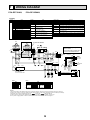
8
REFRIGERANT SYSTEM DIAGRAM
PCA-RP71HAQ
PCA-RP125HAQ
Strainer
#50
Heat exchanger
Refrigerant GAS pipe connection
(Flare)
Condenser/evaporator
temperature thermistor
(TH5)
Refrigerant flow in cooling
Refrigerant flow in heating
Refrigerant LIQUID pipe connection
(Flare)
Pipe temperature
thermistor/liquid
(TH2)
Room temperature
thermistor (TH1)
Distributor
with strainer
#50
Strainer
#50
14
9
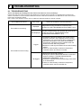
TROUBLESHOOTING
9-1. TROUBLESHOOTING
<Error code display by self-diagnosis and actions to be taken for service (summary)>
Present and past error codes are logged and displayed on the wired remote controller or controller board of outdoor unit.
Actions to be taken for service and the trouble reoccurrence at field are summarized in the table below. Check the contents
below before investigating details.
Note : Refer to the manual of outdoor unit for malfunction-diagnosis method by remote controller.
Unit conditions at service
Error code
Actions to be taken for service (summary)
Displayed
Judge what is wrong and take a corrective action
according to “SELF-DIAGNOSIS ACTION TABLE” (9-2).
Not displayed
Conduct troubleshooting and ascertain the cause of the
trouble according to “TROUBLESHOOTING
BY INFERIOR PHENOMENA ” (9-3).
The trouble is reoccurring.
Consider the temporary defects such as the work of
protection devices in the refrigerant circuit including
compressor, poor connection of wiring, noise and etc.
Re-check the symptom, and check the installation
environment, refrigerant amount, weather when the
trouble occurred, and wiring related.
Reset error code logs and restart the unit after finishing
service.
There is no abnormality in electrical components,
controller boards, and remote controller.
Logged
The trouble is not reoccurring.
Recheck the abnormal symptom.
Identify the cause of the trouble and take a corrective
action according to “TROUBLESHOOTING BY
INFERIOR PHENOMENA ” (9-3).
Continue to operate unit for the time being if the cause
is not ascertained.
There is no abnormality in electrical components,
controller boards, remote controller etc.
Not logged
15
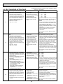
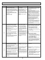
9-2. SELF-DIAGNOSIS ACTION TABLE
Error Code
P1
Note: Refer to the manual of outdoor unit for the details of display
such as F, U, and other E.
Abnormal point and detection method
Cause
Countermeasure
Room temperature thermistor (TH1)
1 The unit is in 3-minute resume
prevention mode if short/open of
thermistor is detected. Abnormal if the
unit does not reset normally after 3 minutes. (The unit returns to normal operation, if it has been reset normally.)
2 Constantly detected during cooling,
drying, and heating operation.
Short: -90: or more
Open: -40: or less
1 Defective thermistor
characteristics
2 Contact failure of connector
(CN20) on the indoor controller
board (Insert failure)
3 Breaking of wire or contact
failure of thermistor wiring
4 Defective indoor controller
board
1–3 Check resistance value of thermistor.
0: 15.0k"
10:
9.6k"
20:
6.3k"
30:
4.3k"
40:
3.0k"
If you put force on (draw or bend) the lead wire
with measuring resistance value of thermistor,
breaking of wire or contact failure can be
detected.
2 Check contact failure of connector (CN20)
on the indoor controller board. Refer to 9-6.
Turn the power on again and check restart
after inserting connector again.
4 Check room temperature display on remote
controller.
Replace indoor controller board if there is
abnormal difference with actual room
temperature.
Turn the power off, and on again to operate
after check.
P2
Pipe temperature thermistor/Liquid
(TH2)
1 The unit is in 3-minute resume
prevention mode if short/open of
thermistor is detected. Abnormal if the
unit does not reset normally after 3 minutes. (The unit returns to normal operation, if it has been reset normally.)
2 Constantly detected during cooling,
drying, and heating (except defrosting)
operation.
Short: 90: or more
Open: -40: or less
1 Defective thermistor
characteristics
2 Contact failure of connector
(CN44) on the indoor controller board (Insert failure)
3 Breaking of wire or contact
failure of thermistor wiring
4 Defective refrigerant circuit is
causing thermistor temperature of 90: or more or -40:
or less.
5 Defective indoor controller
board
1–3 Check resistance value of thermistor.
For characteristics, refer to (P1) above.
2 Check contact failure of connector (CN44) on
the indoor controller board. Refer to 9-6. Turn
the power on and check restart after inserting
connector again.
4 Check pipe <liquid> temperature with remote
controller in test run mode. If pipe <liquid>
temperature is extremely low (in cooling
mode) or high (in heating mode), refrigerant
circuit may have defective.
5 Check pipe <liquid> temperature with
remote controller in test run mode. If there is
extremely difference with actual pipe <liquid>
temperature, replace indoor controller board.
Turn the power off, and on again to operate
after check.
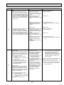
P4
P5
Drain sensor (DS)
1 Suspensive abnormality, if short/open
of thermistor is detected for 30 seconds
continuously. Compressor and indoor fan
will be turned off
2 Short/open is detected for 30 seconds
continuously during suspensive
abnormality.
(The unit returns to normal operation,
if it has normally reset.)
3 Detect the following condition.
• During cooling and drying operation.
• In case that pipe <liquid> temperature room temperature <-10deg
(Except defrosting)
• When pipe <liquid> temperature or
room temperature is short/open
temperature.
• During drain pump operation.
1 Defective thermistor
characteristics
2 Contact failure of connector
(CN31) on the indoor controller
board (Insert failure)
3 Breaking of wire or contact
failure of drain sensor wiring
4 Defective indoor controller board
Malfunction of drain pump (DP)
1 Suspensive abnormality, if thermistor
of drain sensor is let heat itself and
temperature rises slightly. Compressor
and indoor fan will be turned off.
2 Drain pump is abnormal if the condition
above is detected during suspensive
abnormality.
3 Constantly detected during drain pump
operation.
1 Malfunction of drain pump
2 Defective drain
Clogged drain pump
Clogged drain pipe
3 Attached drop of water at the
drain sensor
• Drops of drain trickles from
lead wire
• Clogged filter is causing
wave of drain.
4 Defective indoor controller board
1–3 Check resistance value of thermistor.
0:......6.0k"
10:....3.9k"
20:....2.6k"
30:....1.8k"
40:....1.3k"
2 Check contact failure of connector (CN31) on
the indoor controller board. Refer to 9-6. Turn
the power on again and check restart after
inserting connector again.
4 Replace indoor controller board if drain
pump operates with the line of drain sensor
connector CN31-1 and 2 is short-circuited,
and abnormality reappears.
Turn the power off, and on again to operate
after check.
16
1 Check if drain pump operates.
2 Check drain function.
3 Check the setting of lead wire of drain sensor
and check clogs of the filter.
4 Replace indoor controller board if drain
pump operates with the line of drain sensor
connector CN31-1 and 2 is short-circuited
and abnormality reappears.
Refer to 9-6.
Turn the power off, and on again to operate
after check.
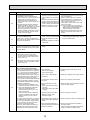
Error Code
P6
Abnormal point and detection method
Freezing/overheating protection is operating
1 Freezing protection (Cooling mode)
The unit is in 6-minute resume prevention mode if pipe <liquid or condenser/
evaporator> temperature stays under
-15: for 3 minutes, 3 minutes after the
compressor started. Abnormal if it stays
under -15: for 3 minutes again within
16 minutes after 6-minute resume prevention mode.
2 Overheating protection (Heating mode)
The units is in 6 minute resume
prevention mode if pipe <condenser /
evaporator> temperature is detected as
over 70: after the compressor started.
Abnormal if the temperature of over
70: is detected again within 30 minutes
after 6 minute resume prevention mode.
Pipe temperature
<Cooling mode>
Detected as abnormal when the pipe temperature is not in the cooling range 3 minutes after compressor start and 6 minutes
after the liquid or condenser/evaporator
pipe is out of cooling range.
Note 1) It takes at least 9 minutes to
detect.
Note 2) Abnormality P8 is not detected in
drying mode.
Cooling range : -3 °C ] (TH-TH1)
TH: Lower temperature between: liquid
pipe temperature (TH2) and condenser/evaporator temperature (TH5)
TH1: Intake temperature
P8
<Heating mode>
When 10 seconds have passed after the
compressor starts operation and the hot
adjustment mode has finished, the unit is
detected as abnormal when condenser/
evaporator pipe temperature is not in heating range within 20 minutes.
Cause
(Cooling or drying mode)
1 Clogged filter (reduced airflow)
2 Short cycle of air path
3 Low-load (low temperature)
operation out of the tolerance
range
4 Defective indoor fan motor
• Fan motor is defective.
• Indoor controller board is defective.
Countermeasure
(Cooling or drying mode)
1 Check clogs of the filter.
2 Remove blockage.
4 Refer to 9-6.
5 Defective outdoor fan control
6 Overcharge of refrigerant
7 Defective refrigerant circuit
(clogs)
5 Check outdoor fan motor.
67 Check operating condition of refrigerant
circuit.
(Heating mode)
1 Clogged filter (reduced airflow)
2 Short cycle of air path
3 Over-load (high temperature)
operation out of the tolerance
range
4 Defective indoor fan motor
• Fan motor is defective.
• Indoor controller board is defective.
5 Defective outdoor fan control
6 Overcharge of refrigerant
7 Defective refrigerant circuit
(clogs)
8 Bypass circuit of outdoor unit
is defective.
(Heating mode)
1 Check clogs of the filter.
2 Remove blockage.
1 Slight temperature difference
between indoor room
temperature and pipe <liquid
or condenser / evaporator>
temperature thermistor
• Shortage of refrigerant
• Disconnected holder of pipe
<liquid or condenser /
evaporator> thermistor
• Defective refrigerant circuit
2 Converse connection of
extension pipe (on plural units
connection)
3 Converse wiring of indoor/
outdoor unit connecting wire
(on plural units connection)
4 Defective detection of indoor
room temperature and pipe
<condenser / evaporator>
temperature thermistor
5 Stop valve is not opened
completely.
1~4 Check pipe <liquid or condenser / evaporator> temperature with room temperature display on remote controller and
outdoor controller circuit board.
Pipe <liquid or condenser / evaporator>
temperature display is indicated by setting SW2 of outdoor controller circuit
board as follows.
Note 3) It takes at least 27 minutes to
detect abnormality.
Note 4) It excludes the period of defrosting.
(Detection restarts when defrosting
mode is over.)
Heating range : 3 °C [ (TH5-TH1)
17
4 Refer to 9-6.
5 Check outdoor fan motor.
6~8Check operating condition of refrigerant
circuit.
(
Conduct temperature check with outdoor
controller circuit board after connecting
‘A-Control Service Tool(PAC-SK52ST)’.
)
23Check converse connection of extension
pipe or converse wiring of indoor/outdoor
unit connecting wire.
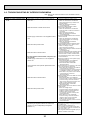
Error Code
P9
Abnormal point and detection method
Pipe temperature thermistor /
Condenser-Evaporator (TH5)
1 The unit is in 3-minute resume protection mode if short/open of thermistor is
detected. Abnormal if the unit does not
get back to normal within 3 minutes. (The
unit returns to normal operation, if it has
been reset normally.)
2 Constantly detected during cooling,
drying, and heating operation (except
defrosting)
Short: 90: or more
Open: -40: or less
Countermeasure
Cause
1 Defective thermistor
1–3 Check resistance value of thermistor.
For characteristics, refer to (P1) above.
characteristics
2 Check contact failure of connector (CN44)
2 Contact failure of connector
on the indoor controller board.
(CN44) on the indoor controller
Refer to 9-7.
board (Insert failure)
Turn the power on and check restart after
3 Breaking of wire or contact
inserting connector again.
failure of thermistor wiring
4 Operate in test run mode and check pipe
4 Temperature of thermistor is
<condenser / evaporator> temperature with
90: or more or -40: or less
outdoor controller circuit board. If pipe
caused by defective refrigerant
<condenser / evaporator> temperature is
circuit.
extremely low (in cooling mode) or high (in
heating mode), refrigerant circuit may have
5 Defective indoor controller
defect.
board
5 Operate in test run mode and check pipe
<condenser / evaporator> temperature with
outdoor control circuit board. If there is
extreme difference with actual pipe
<condenser / evaporator> temperature,
replace indoor controller board.
There is no abnormality if none of above
comes within the unit.
Turn the power off and on again to operate.
In case of checking pipe temperature
with outdoor controller circuit board,
be sure to connect A-control service
tool (PAC-SK52ST).
(
Remote controller transmission
error(E0)/signal receiving error(E4)
1 Abnormal if main or sub remote controller cannot receive any transmission
normally from indoor unit of refrigerant
address “0” for 3 minutes.
(Error code : E0)
2 Abnormal if sub remote controller could
not receive any signal for 2 minutes.
(Error code: E0)
E0
or
E4
E3
or
E5
1 Abnormal if indoor controller board can
not receive any data normally from
remote controller board or from other
indoor controller board for 3 minutes.
(Error code: E4)
2 Indoor controller board cannot receive
any signal from remote controller for 2
minutes. (Error code: E4)
Remote controller transmission
error(E3)/signal receiving error(E5)
1 Abnormal if remote controller could not
find blank of transmission path for 6 seconds and could not transmit.
(Error code: E3)
2 Remote controller receives transmitted
data at the same time and compares the
received and transmitted data. Abnormal
if these data are judged to be different
30 continuous times. (Error code: E3)
1 Contact failure at transmission
wire of remote controller
2 All remote controllers are set
as “sub” remote controller.
In this case, E0 is displayed
on remote controller, and E4
is displayed at LED (LED1,
LED2) on the outdoor controller
circuit board.
3 Miswiring of remote controller
4 Defective transmitting receiving
circuit of remote controller
5 Defective transmitting receiving
circuit of indoor controller board
of refrigerant addresses “0”.
6 Noise has entered into the
transmission wire of remote
controller.
)
1 Check disconnection or looseness of indoor
unit or transmission wire of remote controller.
2 Set one of the remote controllers “main”
if there is no problem with the action above.
3 Check wiring of remote controller.
• Total wiring length: max. 500 m
(Do not use cable × 3 or more.)
• The number of connecting indoor units:
max. 16 units
• The number of connecting remote controller: max. 2 units
When it is not the above-mentioned problem of
1~3
4 Diagnose remote controllers.
a) When “RC OK” is displayed,
Remote controllers have no problem.
Turn the power off, and on again to check.
If abnormality generates again, replace
indoor controller board.
b) When “RC NG” is displayed,
Replace remote controller.
c) When “RC E3” or “ERC 00-66” is displayed, noise may be causing abnormality.
* If the unit is not normal after replacing
indoor controller board in group control,
indoor controller board of address “0” may
be abnormal.
1 2 remote controllers are set as 1 Set a remote controller to main, and the
“main.”
other to sub.
(In case of 2 remote controllers)
2 Remote controller is connected 2 Remote controller is connected with only one
with 2 indoor units or more.
indoor unit.
3 Repetition of refrigerant
3 The address changes to a separate setting.
address
4 Defective transmitting receiving 4~6 Diagnose remote controller.
circuit of remote controller
a) When “RC OK” is displayed, remote controllers have no problem.
1 Abnormal if indoor controller board could 5 Defective transmitting receiving
Turn the power off, and on again to check.
not find blank of transmission path.
circuit of indoor controller board
When becoming abnormal again, replace
(Error code: E5)
6 Noise has entered into transindoor controller board.
2 Indoor controller board receives transmission wire of remote controlb) When “RC NG” is displayed, replace
mitted data at the same time and comler.
remote controller.
pares the received and transmitted data.
c) When “RC E3” or “ERC 00-66” is disAbnormal if these data are judged to
played, noise may be causing abnormality.
be different 30 continuous times. (Error
code: E5)
18
Countermeasure
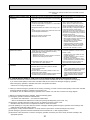
Error Code
Abnormal point and detection method
E6
Indoor/outdoor unit communication
error (Signal receiving error)
1 Abnormal if indoor controller board
cannot receive any signal normally for 6
minutes after turning the power on.
2 Abnormal if indoor controller board
cannot receive any signal normally for 3
minutes.
3 Consider the unit abnormal under the
following condition: When 2 or more
indoor units are connected to an outdoor
unit, indoor controller board cannot
receive a signal for 3 minutes from
outdoor controller circuit board, a signal
which allows outdoor controller circuit
board to transmit signals.
E7
Indoor/outdoor unit communication
1 Defective transmitting receiving 1-3 Turn the power off, and on again to check.
circuit of indoor controller board
error (Transmitting error)
If abnormality generates again, replace
Abnormal if “1” receiving is detected 30
2 Noise has entered into power
indoor controller board.
supply.
times continuously though indoor controller
board has transmitted “0”.
3 Noise has entered into outdoor
control wire.
1 Defective indoor controller
board
1 Replace indoor controller board.
Fb
Indoor controller board
Abnormal if data cannot be read normally
from the nonvolatile memory of the indoor
controller board.
Remote controller control board
1 Abnormal if data cannot be read
normally from the nonvolatile memory
of the remote controller control board.
(Error code: E1)
1 Defective remote controller
1 Replace remote controller.
E1
or
E2
PA
Cause
1 Contact failure, short circuit or,
miswiring (converse wiring) of
indoor/outdoor unit connecting
wire
2 Defective transmitting receiving
circuit of indoor controller board
3 Defective transmitting receiving
circuit of indoor controller board
4 Noise has entered into indoor/
outdoor unit connecting wire.
* Check LED display on the outdoor control
circuit board. (Connect A-control service
tool, PAC-SK52ST.)
Refer to outdoor unit service manual.
1 Check disconnection or looseness of
indoor/ outdoor unit connecting wire of
indoor unit or outdoor unit.
Check all the units in case of twin triple
indoor unit system.
2-4 Turn the power off, and on again to
check. If abnormality generates again,
replace indoor controller board or
outdoor controller circuit board.
* Other indoor controller board may have
defect in case of twin triple indoor unit
system.
2 Abnormal if the clock function of remote
controller cannot be operated normally.
(Error code: E2)
Forced compressor stop
(due to water leakage abnormality)
1 When the intake temperature subtracted
with liquid pipe temperature is less than
-10:, drain sensor is detected whether
it is soaked in the water or not at the
interval of 90 seconds. (Drain pump will
start operating when the drain sensor is
detected to be soaked in the water.)
2 The unit has a water leakage abnormality
when the following conditions, a and b,
are satisfied while the above-mentioned
detection is performed.
a) The drain sensor is detected to be
soaked in the water 10 times in a row.
b) The intake temperature subtracted
with liquid pipe temperature is
detected to be less than -10: for a
total of 30 minutes.
(When the drain sensor is detected
to be NOT soaked in the water, the
detection record of a and b will be
cleared.)
3 The drain sensor detection is performed
in operations other than cooling. (When
the unit stops operating, during heating
or fan operation, when the unit stops
because of some abnormality)
*Once the water leakage abnormality is
detected, abnormality state will not be
released until the main power is reset.
1 Drain pump trouble
1 Check the drain pump.
2 Drain defective
· Drain pump clogging
· Drain pipe clogging
2 Please confirm whether water can be
drained.
3 Open circuit of drain sensor
side heater
3 Confirm the resistance of the drain sensor.
4 Contact failure of drain sensor
connector
4 Check the connector contact failure.
5 Dew condensation on drain
sensor
· Drain water descends along
lead wire.
· Drain water waving due to filter
clogging.
5 Check the drain sensor leadwire mounted.
Check the filter clogging
6 Extension piping connection
difference at twin, triple,
quadruple system.
6 Check the piping connection.
7 Mis-wiring of indoor/ outdoor con- 7 Check the indoor/ outdoor connecting wires.
necting at twin, triple, quadruple
system.
8 Room temperature thermistor /
8 Check the room temperature display of
liquid pipe temperature thermistor
remote controller.
Check the indoor liquid pipe temperature
detection is defective.
display of outdoor controller board.
19
9-3. TROUBLESHOOTING BY INFERIOR PHENOMENA
Note: Refer to the manual of outdoor unit for the detail of remote
controller.
Phenomena
(1)LED2 on indoor controller board
is off.
Cause
• When LED1 on indoor controller board is also off.
1 Power supply of rated voltage is not supplied to outdoor unit.
2 Defective outdoor controller circuit board.
3 Power supply of 220~240V is not supplied to indoor
unit.
4 Defective indoor power board.
5 Defective indoor controller board.
(For the separate indoor/outdoor unit power supply system)
1 Power supply of 220~240V AC is not supplied to
indoor unit.
2 The connectors of the optional replacement kit are
not used.
3 Defective indoor controller board.
4 Defective indoor power board.
• When LED1 on indoor controller board is lit.
1 Mis-setting of refrigerant address for outdoor unit
(There is no unit corresponding to refrigerant
address “0”.)
20
Countermeasure
1 Check the voltage of outdoor power
supply terminal block (L, N) or (L3, N).
• When AC 220~240V is not detected.
Check the power wiring to outdoor unit
and the breaker.
• When AC 220~240V is detected.
—Check 2 (below).
2 Check the voltage between outdoor
terminal block S1 and S2.
• When AC 220~240V is not detected.
Check the fuse on outdoor controller circuit board.
Check the wiring connection.
• When AC 220~240V is detected.
—Check 3 (below).
3 Check the voltage between indoor terminal
block S1 and S2.
• When AC 220~240V is not detected.
Check indoor/outdoor unit connecting
wire for mis-wiring.
• When AC 220~240V is detected.
—Check 4 (below).
4 Check voltage output from CN2S on indoor
power board (DC13.1V). Refer to 9-6-1.
• When no voltage is output.
Check the wiring connection.
• When output voltage is between DC12.5V
and DC13.7V.
—Check 5 (below).
5 Check the wiring connection between indoor
controller board and indoor power board.
Check the fuse on indoor controller board.
If no problems are found, indoor controller
board is defective.
1 Check the voltage of indoor power supply
terminal block (L,N).
• When AC220~240V is not detected.
Check the power supply wiring.
• When AC220~240V is detected.
-Check 2 (below).
2 Check that there is no problem in the method of connecting the connectors.
• When there are problems in the method
of connecting the connectors.
Connect the connector correctly referring
to installation manual of an optional kit.
• When there is no problem in the method
of connecting the connectors.
-Check 3 (below).
3 Check voltage output from CNDK on indoor
controller board.
• When AC220~240V is not detected.
Check the fuse on indoor controller board.
Check the wiring connection between
indoor power supply terminal block and
CND on indoor controller board.
• When AC220~240V is detected.
-Check 4 (below).
4 Check voltage output from CN2S on indoor
power board.
• When no voltage output.
Check the wiring connection between
CNDK on indoor controller board and
CNSK on indoor power board.
If no problem are found, indoor power
board is defective.
• When DC12.5~13.7V is detected.
Check the wiring connection between
CN2S on indoor power board and
CN2D on indoor power board.
If no problem are found, indoor controller
board is defective.
1 Reconfirm the setting of refrigerant address
for outdoor unit
Set the refrigerant address to “0”.
(For grouping control system under which
2 or more outdoor units are connected, set
one of the units to “0”.)
Set refrigerant address using SW1 (3-6) on
outdoor controller circuit board.
Note: Refer to the manual of outdoor unit for the detail of remote
controller.
Phenomena
(2)LED2 on indoor controller board
is blinking.
Cause
Countermeasure
• When LED1 on indoor controller board is also blinking. Check indoor/outdoor unit connecting wire
Connection failure of indoor/outdoor unit connecting for connection failure.
wire
• When LED1 is lit.
1 Check the connection of remote controller
wires in case of twin triple indoor unit
1 Mis-wiring of remote controller wires
Under twin triple indoor unit system, 2 or more indoor
system. When 2 or more indoor units are
units are wired together.
wired in one refrigerant system, connect
remote controller wires to one of those units.
2 Refrigerant address for outdoor unit is wrong or not 2 Check the setting of refrigerant address
set.
in case of grouping control system.
Under grouping control system, there are some units
If there are some units whose refrigerant
whose refrigerant address is 0.
addresses are 0 in one group, set one of
the units to 0 using SW1 (3-6) on outdoor
controller circuit board.
3 Short-cut of remote controller wires
34 Remove remote controller wires and
check LED2 on indoor controller board.
4 Defective remote controller
• When LED2 is blinking, check the shortcut of remote controller wires.
• When LED2 is lit, connect remote
controller wires again and:
if LED2 is blinking, remote controller
is defective; if LED2 is lit, connection
failure of remote controller terminal
block etc. has returned to normal.
(3)Upward/downward vane
performance failure
1 The vane is not downward during defrosting and heat 1 Normal operation (The vane is set to
preparation and when the thermostat is OFF in HEAT
horizontal regardless of remote control.)
mode. (Working of COOL protection function)
2 Vane motor does not rotate.
2 Check 2 (left).
• Defective vane motor
• Check the vane motor. (Refer to “How
• Breaking of wire or connection failure of connector
to check the parts”.)
• Up/down vane setting is “No vanes”.
• Check for breaking of wire or connection failure of connector.
• Check “Up/down vane setting”. (Unit
function selection by remote controller).
3 Upward/downward vane does not work.
3 Normal operation (Each connector on
• The vane is set to fixed position.
vane motor side is disconnected.)
(4)Receiver for wireless remote
controller
1 Weak batteries of wireless remote controller.
1 Replace batteries of wireless remote controller.
2~4
2 Contact failure of connector (CNB) on wireless
remote controller board.
Check contact failure of each connector.
If no problems are found of connector,
(Insert failure)
replace indoor controller board.
3 Contact failure of connector (CN90) on indoor controller board. (Insert failure)
When the same trouble occurs even if
indoor controller board is replaced,
4 Contact failure of connector between wireless remote
replace wireless remote controller
controller board and indoor controller board.
board.
9-4. WHEN WIRED REMOTE CONTROLLER OR INDOOR UNIT MICROPROCESSOR FAILS
1. When the wired remote control or the indoor unit microprocessor has failed, but all other components work properly,
if you set the switch (SWE) on the indoor controller board ON, the indoor unit will begin emergency operation.
When emergency operation is activated, the indoor unit operates as follows:
• Indoor fan is running at high speed.
2. When you activate emergency operation of the cooling or heating, you have to set the switch (SWE) on the indoor controller
board and activate emergency operation of the outdoor unit.
For details on how to activate emergency operation of the outdoor unit, refer to the outdoor unit wiring diagram.
3. Before you activate emergency operation, check the following points:
(1) Emergency operation cannot be activated when:
• the outdoor unit malfunctions. • the indoor fan malfunctions.
• when it has detected the malfunction of drain pump during self-diagnosing. (Error code : P5)
(2) Emergency operation becomes continuous only by switching the power source on/off.
ON/OFF on the remote control or temperature control etc. does not function.
(3) Avoid operating for a long time when the outdoor unit begins defrosting while emergency operation of the heating is activated because it will start to blow cold air.
(4) Emergency cooling should be limited to 10 hours maximum (The indoor unit heat exchanger may freeze).
(5) After emergency operation has been deactivated set the switches etc. to their original positions.
(6) Movement of the vanes does not work in emergency operation, therefore you have to slowly set them manually to the
appropriate position.
21
9-5. HOW TO CHECK THE PARTS
PCA-RP71HAQ
PCA-RP125HAQ
Parts name
Check points
Disconnect the connector then measure the resistance with a tester.
(At the ambient temperature 10~30)
Room temperature
thermistor
(TH1)
Pipe temperature
thermistor
(TH2)
Condenser/Evaporator
temperature thermistor
(TH5)
Fan motor(MF)
Abnormal
4.3k~9.6k
Open or short
(Refer to <Thermistor Characteristic graph> for a detail.)
Measure the resistance between the terminals with a tester.
(Winding temperature 20)
Relay
connector
Protector
Normal
Connector
White
Normal
PCA-RP71
PCA-RP125
White–Black
140.5
75.6
Black–Blue
15.4
36.7
Yellow
Blue–Yellow
28.5
23.6
Blue
Yellow–Red
80.4
47.8
Orange
Red
Abnormal
Open or short
Protector
OPEN : 135±5
CLOSE : 95±15
Black
<Thermistor Characteristic graph>
< Thermistor for lower temperature >
Thermistor R0=15kΩ ± 3%
Fixed number of B=3480kΩ ± 2%
Rt=15exp { 3480(
0:
10:
20:
25:
30:
40:
1
273+t
50
40
Resistance (K)
Thermistor for
lower temperature
Room temperature thermistor(TH1)
Pipe temperature thermistor(TH2)
Condenser/evaporator temperature
thermistor(TH5)
1 )}
273
15kΩ
9.6kΩ
6.3kΩ
5.4kΩ
4.3kΩ
3.0kΩ
30
20
10
0
22
-20 -10 0 10 20 30 40 50
Temperature ()
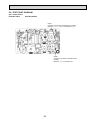
9-6. TEST POINT DIAGRAM
9-6-1. Power board
PCA-RP71HAQ
PCA-RP125HAQ
CN2S
Connect to the indoor controller board (CN2D)
Between 1 to 3 12.6-13.7V DC (Pin1 (+))
CNSK
Connect to the indoor controller board
(CNDK)
Between 1 to 3 220-240V AC
23
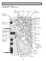
9-6-2. Indoor controller board
CN2D
Connector to the indoor
power board (CN2S)
(12.5~13.7V DC)
LED1
Power supply
(I.B)
LED3
Transmission
(Indoor/outdoor)
LED2
Power supply
(R.B)
}
–
+
CN3C
Transmission
(Indoor/outdoor)
(0~24V DC)
PCA-RP125HAQ
+
PCA-RP71HAQ
–
CND
Power
supply input
(220~240V AC)
CN22
Remote controller
connecting wire
(10.4~14.6V DC)
CN20
Room temperature
thermistor (TH1)
}
CN21
Pipe temperature
thermistor/Liquid
(TH2)
CN29
Condenser/evaporator
temperature thermistor
(TH5)
FUSE
(6.3A 250V)
CN31
Drain sensor (DS)
CNDK
Connect to the indoor
power board (CNSK)
(220~240V AC)
CN90
Connect to the wireless remote controller
board (CNB)
CNP
Drain-pump output
(DP)
(220~240V AC)
CN41
Connector
(HA terminal-A)
CNC
Dew prevention
heater (H2)
(220~240V AC)
CN6V
Vane motor output
(MV)
CN51
Centrally control
1-2 : Control signal
13V pulse input (1 : +)
3-4 : Operation indicator
13VDC (3 : +)
3-5 : Malfunction indicator
13VDC (3 : +)
CN2L
Connector
(LOSSNAY)
FAN
Fan motor output
SW1
Model setting
SWE
Emergency operation
24
SW2
Capacity setting
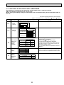
9-7. FUNCTIONS OF DIP SWITCH AND JUMPER WIRE
Each function is controlled by the dip switch and the jumper wire on control P.C. board.
SW1 and SW2 are equipped only for service parts.
Model setting and capacity setting are memorized in the nonvolatile memory of the control P.C. board of
the unit.
The black square (■) indicates a switch position.
(Marks in the table below)
Jumper wire
Functions
Setting by the dip switch and jumper wire
Jumper wire (
: Short
: Open)
Remarks
For service board
SW1
Model
settings
1
2
3
4
5
ON
OFF
Service board
MODELS
SW2
Capacity
settings
PCA-RP71HAQ
PCA-RP125HAQ
J41
J42
Pair number
setting with
wireless
remote
controller
JP1
Unit type
setting
JP3
Indoor
controller
board type
setting
1 2 3 4 5
1 2 3 4 5
ON
OFF
ON
OFF
Wireless remote Control PCB setting
controller setting
J41
J42
0
1
2
3~9
Model
Without TH5
With TH5
JP1
Indoor controller board type
For product
Service parts
<Initial setting>
Wireless remote controller: 0
Control PCB: (for both J41 and J42)
Four pair number settings are supported.
The pair number settings of the wireless remote
controller and indoor control PCB (J41/J42) are
given in the table on the left.
(' ' in the table indicates the jumper line is disconnected.)
There is no jumper (JP1) because these models
have the cond./eva. temperature thermistor (TH5).
JP3
25
10
SPECIAL FUNCTION
10-1. ROTATION FUNCTION (AND BACK-UP FUNCTION, 2ND STAGE CUT-IN FUNCTION)
10-1-1. Operation
(1) Rotation function (and Back-up function)
• Outline of functions
· Main and sub unit operate alternately according to the interval of rotation setting.
w Main and sub unit should be set by refrigerant address. (Outdoor Dip switch setting)
Refrigerant address "00"
Main unit
Refrigerant address "01"
Sub unit
· When error occurs to one unit, another unit will start operation. (Back-up function)
• System constraint
· This function is available only by the grouping control system (INDOOR UNIT : OUTDOOR UNIT=1:1) of 2 refrigerant
groups. (Refer to Fig. 1)
· Main indoor unit should be connected for wired remote controller and the transmission line (TB5) for main and sub unit
should also be connected. (Refer to Fig. 1)
(This function cannot be set by wireless remote controller.)
· Set refrigerant address of each unit. (Dip switch on the outdoor unit···Refrigerant address 00/01)
Fig. 1
Operation pattern
[Back-up function only]··· Request code number "312"
Error occurs on main unit.
Main
Sub
Start operation
Main
unit
IC-1
Sub
unit
IC-2
Refrigerant address
"00"
Run
Abnormal condition
Stop
Run
3(2)
2
Start operation
Sub
unit
IC-2
3(2)
Main
Sub
Sub
Main
Error occurs on main unit.
Main
Sub
Abnormal condition
Run
Stop
Run
Stop
Run
Stop
1~28 days
Sub
unit
IC-2
IC-1
[Rotation function] & [Back-up function]··· Request code number "313~318"
Main
unit
IC-1
OC-2
OC-1
Main
unit
Refrigerant address
"01"
2
RC
OC : Outdoor unit
IC : Indoor unit
RC : Wired remote controller
Run
1~28 days
(Ex:When the request code number is "313", each unit operates alternately in daily cycle.)
Note:
· When the unit is restarted to operate after turning off the power or OFF operation, the unit which was operating will start
operation.
· To operate the main unit, refer to the 10-1-2. and set the request code No. which is not the same as the current one, and set
again the former request code No.
(2) 2nd stage cut-in function
Outline of functions
· Number of operating units is determined according to the room temperature and set point.
· When room temperature becomes higher than set point, standby unit starts. (2 units operation)
· When room temperature falls below set point -4:, standby unit stops. (1 unit operation)
System constraint
[2nd stage cut-in function]··· Request code number "322~324"
· This function is available only in rotation operation and back-up function in
Room temp. Set point
Room temp. < Set point -4
cooling mode.
Start operation
Sub unit start operation
Sub unit stop
Main
unit
IC-1
Sub
unit
IC-2
Run
Stop
26
Run
Stop
10-1-2. How to set rotation function (Back-up function, 2nd stage cut-in function)
You can set these functions by wired remote controller. (Maintenance monitor)
NOTICE
Both main and sub unit should be set in same setting.
Every time replacing indoor controller board for servicing, the function should be set again.
(1) Request Code List
Rotation setting
Setting No.
(Request code)
No.1
(310)
No.2
(311)
No.3
(312)
No.4
(313)
No.5
(314)
No.6
(315)
No.7
(316)
No.8
(317)
No.9
(318)
Setting contents
Initial
setting
Monitoring the request code of current setting.
Rotation and Back-up OFF (Normal group control operation)
Back-up function only
Rotation ON (Alternating interval = 1day) and back up function
Rotation ON (Alternating interval = 3day) and back up function
Rotation ON (Alternating interval = 5day) and back up function
Rotation ON (Alternating interval = 7day) and back up function
Rotation ON (Alternating interval = 14day) and back up function
Rotation ON (Alternating interval = 28day) and back up function
2nd stage cut-in setting
Setting No.
(Request code)
No.1
(320)
No.2
(321)
No.3
(322)
No.4
(323)
No.5
(324)
Initial
setting
Setting contents
Monitoring the request code of current setting.
Cut-in function OFF
Cut-in Function ON(Set point = Set temp.+ 4°C(7.2°F))
Cut-in Function ON(Set point = Set temp.+ 6°C(10.8°F))
Cut-in Function ON(Set point = Set temp.+ 8°C(14.4°F))
27
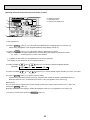
(2) Setting method of each function by wired remote controller
B: Refrigerant address
C: Data display area
D: Request code display area
1. Stop operation(
).
2. Press the TEST button () for 3 seconds so that [Maintenance mode] appears on the screen ().
After a while, [00] appears in the refrigerant address number display area.(at )
3. Press the CHECK button () for 3 seconds to switch to [Maintenance monitor].
Note) It is not possible to switch to [Maintenance monitor] during data request in maintenance mode
(i.e., while “----” is blinking) since no buttons are operative.
[----] appears on the screen () when [Maintenance monitor] is activated.
(The display () now allows you to set a request code No.)
4. Press the [TEMP (
[ScreenB]
5. Press the [CLOCK (
and
)] buttons () to select the desired refrigerant address.
and
)] buttons () to set the desired request code No.(“311~318”, “321~324”)
6. Press the FILTER button () to perform function setting.
If above setting operations are done correctly, "Request code number will appear in data display area.()
[Example: When the "311" of "Request code number" is set, [311] appears on the screen.()]
[Refererence]
You can check current "request code number" setting by setting the "request code number"(“310” or “320”) and
pressing the FILTER button.()
[Example: When the current setting is "Setting No.2(Request code 311)", [311] appears on the screen.()]
7. To return to normal mode, press the ON/OFF button (
).
28
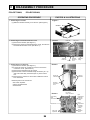
11
DISASSEMBLY PROCEDURE
PCA-RP71HAQ
PCA-RP125HAQ
OPERATING PROCEDURE
PHOTOS & ILLUSTRATIONS
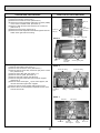
1. Removing the oil filter
(1) Slide the oil filter towards you to remove. (See Figure 1)
Figure 1
Oil filter
e
Slid
2. Removing the terminal block box cover
(1) Remove the oil filter. (See Figure 1)
(2) Remove a screw for terminal block box cover, and remove
the terminal block box cover. (See Photo 1)
Photo 1
Filter rails
Terminal
block box
Screw
3. Removing the control box
(1) Remove the oil filter. (See Figure 1)
(2) Loosen the screw for control box cover to remove the
control box cover. (See Photo 2)
(3) Remove the lead wire from the 2 clips.
(4) Remove the 2 white cord heater relay connectors (1P o 2)
and 2 fan motor relay connectors (6P o 2) in the control
box.
(5) Remove the 2 screws for control box to slide the control
box downward.
Electrical parts in the control box
• Fan motor capacitor
• Indoor controller board
• Power board
Fan guard
Terminal
block box
cover
Clamp for
wiring
Photo 2
Screws for
control box
Clips for
lead wire
Screw for
control box
cover
Photo 3
Cord heater
relay
connectors
Power board
Fan motor
capacitors
29
Fan motor
relay connectors
Pipe
temperature
thermistor
connector
(CN21)
Room
temperature
thermistor
connector
(CN20)
Indoor
controller
board
OPERATING PROCEDURE
PHOTOS & ILLUSTRATIONS
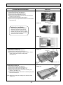
4. Removing the fan motor
(1) Remove the oil filter. (See Figure 1)
(2) Remove the control box cover. (See Photo 2)
(3) Remove the room temperature thermistor connector (CN20)
on the indoor controller board. (See Photo 3)
(4) Remove a filter rail that is the nearest to the control box.
(See Photo 4)
(5) Remove the fan guard. (See Photo 5)
(6) Remove the room temperature thermistor together with the
holder at the right side of the casing.
Photo 4
Filter rail
Room
temperature
thermistor
Screws for
filter rail
Screws for Fan guard
Photo 5
Room
temperature
thermistor
Control box
cover
5. Removing the fan motor and the sirocco fan
(1) Remove the oil filter. (See Figure 1)
(2) Remove the control box cover. (See Photo 2.)
(3) Remove the fan motor relay connectors (6P) in the control
box. (See Photo 3)
(4) Remove the 3 filter rails. (See Photo 1, 4)
(5) Remove the fan guard. (See Photo 5)
(6) Remove the lower casing. (See Photo 6)
(7) Remove the green earth wire from the motor support.
(See Photo 7)
(8) Remove the 2 screws (M5 × 12) for motor support, and
remove the left and right motor supports.
(9) Remove the fan motor together with the sirocco fan.
(10) Remove the 2 set screws (M6) to separate the fan motor
from the sirocco fan.
Fan guard
Screws for Fan guard
Photo 6
Screws for casing
Screws for casing
Control box
cover
Casing
Casing
Fan motor
Photo 7
Earth wire
Sirocco fan
30
Set screws
Screws for
motor support
Motor
support
Sirocco fan
OPERATING PROCEDURE
PHOTOS
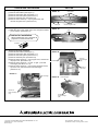
6. Removing the pipe temperature thermistor
(1) Remove the oil filter. (See Figure 1)
(2) Remove the fan guard. (See Photo 1)
(3) Remove the terminal block box cover.
(4) Remove the white relay connector (2P) in the terminal
block box. (See Photo 8)
(5) Remove the service panel. (See Photo 9)
(6) Remove the pipe temperature thermistor from the holder.
(See Photo 10)
Photo 8
Relay connector
Terminal block box
Photo 9
Service panel
Caution for installation
When installing the pipe temperature
thermistor, slack off its lead wire as
shown in the photo. Otherwise, water
trickled down the lead wire may splash
on the connector and this could cause a
short circuit of the connector.
Screws for
service panel
Photo 10
Inspection port
Pipe temperature
thermistor
7. Removing the under panel
(1) Remove the oil filter. (See Figure 1)
(2) Remove the 3 filter rails. (See Photo 1, 4)
(3) Remove the 12 screws (left: 1, right: 1, bottom: 10) for
under panel, and remove the under panel.
(See Photo 11)
Photo 11
Screw for
under panel
(left: 1)
8. Removing the drain pan
(1) Remove the oil filter. (See Figure 1)
(2) Remove the 3 filter rails. (See Photo 1, 4)
(3) Remove the under panel. (See Photo 11)
(4) Pull the blue lead wire for cord heater towards you to
slack off. (See Photo 12)
(5) Remove the 3 screws at the center of the drain pan, and
remove the drain pan.
Slack off
Under panel
Screws for under panel (bottom: 10)
Lead wire for
cord heater
Photo 12
(Note) Remove the drain pan carefully since the drain could
remain in it.
Screws for
drain pan
Drain pan
31
Screw for under panel
(right: 1)
OPERATING PROCEDURE
PHOTOS
9. Removing the guide vane
(1) Remove the oil filter. (See Figure 1)
(2) Remove the 3 filter rails. (See Photo 1, 4)
(3) Remove the under panel. (See Photo 11)
(4) Remove the drain pan. (See Photo 12)
(5) Remove the 3 screws (4 × 10) for guide vane, and
remove the guide vane. (See Photo 13)
Photo 13
Drain pan
10. Removing the vane
(1) Slide the vane to the center of the unit, and pull it towards
you to remove. (See Photo 14)
Guide vanes
Screws for guide vane
Photo 14
Vanes
Caution for installation
When installing the vane, check that its
projection is on the left-rear side.
Slide
Slide
Projection
11. Removing the heat exchanger
(1) Remove the oil filter. (See Figure 1)
(2) Remove the 3 filter rails. (See Photo 1, 4)
(3) Remove the under panel. (See Photo 11)
(4) Remove the drain pan. (See Photo 12)
(5) Remove the 2 screws (4 × 10) for pipe cover, and remove
the pipe cover. (See Photo 15)
(6) Remove the 3 screws (4 × 10, left: 2, right: 1) for heat
exchanger. (See Photo 15, 16)
(7) Remove the 2 screws (4 × 10) for heat exchanger at the
top of the unit, and remove the heat exchanger.
(See Photo 17)
Photo 15
Pipe cover
Screw for
heat exchanger
(right)
Heat exchanger
Screws for
pipe cover
Photo 17
Heat exchanger
Photo 16
Heat exchanger
Screws for
Heat exchanger
(top)
Screws for
Heat exchanger
(left)
HEAD OFFICE : TOKYO BLDG., 2-7-3, MARUNOUCHI, CHIYODA-KU, TOKYO 100-8310, JAPAN
CCopyright 2010 MITSUBISHI ELECTRIC ENGINEERING CO., LTD.
Distributed in Dec. 2010 No.OCH492
Made in Japan
New publication, effective Dec. 2010
Specifications subject to change without notice.