1
MPLS Module Installation
and User Guide
Extreme Networks, Inc.
3585 Monroe Street
Santa Clara, California 95051
(888) 257-3000
http://www.extremenetworks.com
Published: February 2002
Part number: 100084-00 Rev. 02
©2002 Extreme Networks, Inc. All rights reserved. Extreme Networks and BlackDiamond are
registered trademarks of Extreme Networks, Inc. in the United States and certain other jurisdictions.
ExtremeWare, Extreme Standby Router Protocol, ESRP, Summit, and the Extreme Networks logo are
trademarks of Extreme Networks, Inc., which may be registered or pending registration in certain
jurisdictions. Specifications are subject to change without notice.
All other registered trademarks, trademarks, and service marks are property of their respective owners.
ii
Contents
Preface
Introduction
Terminology
xi
xii
Conventions
xii
Related Publications
1
xiii
Overview
Summary of Features
MPLS
IP Unicast Forwarding
Destination-Sensitive Accounting
1-2
1-2
1-2
1-2
MPLS Module Physical Description
MPLS Module LED Indicators
Service Port
Console Port
1-2
1-4
1-5
1-5
BlackDiamond 6800 Series Switch Overview
About BlackDiamond Modules
1-5
1-5
About the MPLS Module
1-6
About MPLS
1-6
About MPLS Layer-2 VPNs
1-7
MPLS Module Installation and User Guide
iii
2
3
About IP Unicast Forwarding
1-8
About Destination-Sensitive Accounting
1-8
Installing or Replacing an MPLS Module
Preparing for Installation
Software and Hardware Version Requirements
Safety Information
Tools
MPLS Module Slot Locations
2-1
2-2
2-3
2-4
2-4
Inserting and Securing a Module
2-6
Verifying the Module Installation
LED Indicators
Displaying Slot Status Information
2-8
2-8
2-8
Troubleshooting
Identifying Problem Categories
Fixing Configuration Errors
Upgrading the Switch Software Image
Upgrading the MPLS Module Software Image
Fixing Power-Related Problems
Identifying Conditions for Replacing an MPLS Module
2-9
2-10
2-11
2-11
2-11
2-12
2-13
Removing and Replacing an MPLS Module
Tools and Equipment
Removing an MPLS Module
2-14
2-14
2-14
Configuring the MPLS Module
Overview of MPLS
MPLS Terms and Acronyms
Label Switched Paths
Label Advertisement Modes
Label Retention Modes
LSP Control Modes
Label Switch Routers
Supporting Quality of Service Features
iv
3-1
3-2
3-4
3-4
3-5
3-6
3-6
3-7
MPLS Module Installation and User Guide
MPLS Layer
MPLS Label Stack
Penultimate Hop Popping
Label Binding
Label Space Partitioning
3-8
3-8
3-10
3-10
3-10
Configuring MPLS
Commands for MPLS
Configuring Interfaces
3-12
3-12
3-15
Configuring the Maximum Transmission Unit Size
Configuring the Propagation of IP TTL
Configuring Penultimate Hop Popping
Configuring QoS Mappings
Dot1p-to-exp Mappings
Exp-to-dot1p Mappings
Resetting MPLS Configuration Parameter Values
Displaying MPLS Configuration Information
Displaying
Displaying
Displaying
Displaying
4
MPLS
MPLS
MPLS
MPLS
Configuration Information
Forwarding Entry Information
Label Mapping Information
QoS Mapping Information
3-16
3-16
3-17
3-17
3-18
3-18
3-19
3-20
3-20
3-20
3-21
3-22
Configuring the Label Distribution Protocol
Overview of LDP
LDP Neighbor Discovery
Advertising Labels
Propagating Labels
4-1
4-1
4-2
4-2
Configuring LDP
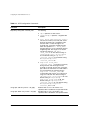
Commands for LDP
Configuring LDP on a VLAN
Configuring LDP Filters
4-3
4-3
4-6
4-6
Configuring an LDP Label Propagation Filter
Configuring an LDP Label Advertisement Filter
Configuring LDP Session Timers
Restoring LDP Session Timers
Displaying LDP Peer Information
Configuration Example
MPLS Module Installation and User Guide
4-6
4-7
4-8
4-9
4-9
4-10
v
5
Configuring RSVP-TE
RSVP Elements
Message Types
5-2
5-2
Path Message
Reservation Message
Path Error Message
Reservation Error Message
Path Tear Message
Reservation Tear Message
Reservation Confirm Message
5-3
5-4
5-4
5-4
5-4
5-5
5-5
Reservation Styles
5-5
Fixed Filter
Shared Explicit
Wildcard
5-6
5-6
5-6
Bandwidth Reservation
5-6
Bandwidth Accounting
RSVP State
5-7
5-7
Traffic Engineering
RSVP Tunneling
RSVP Objects
5-8
5-8
5-9
Label
Label Request
Explicit Route
Record Route
Session Attribute
5-9
5-9
5-9
5-10
5-10
RSVP Features
Route Recording
Explicit Route Path LSPs
Redundant LSPs
5-10
5-11
5-11
5-12
Ping Health Checking
5-13
Improving LSP Scaling
5-13
Configuring RSVP-TE
Commands for Configuring RSVP-TE
Configuring RSVP-TE on a VLAN
Configuring RSVP-TE Protocol Parameters
Configuring an RSVP-TE Path
Configuring an Explicit Route
Configuring an RSVP-TE Profile
Configuring an Existing RSVP-TE Profile
vi
5-14
5-14
5-16
5-17
5-18
5-19
5-20
5-22
MPLS Module Installation and User Guide
Configuring an RSVP-TE LSP
Adding a Path to an RSVP-TE LSP
Displaying RSVP-TE LSP Configuration Information
Displaying the RSVP-TE Routed Path
Displaying the RSVP-TE Path Profile
Displaying the RSVP-TE LSP
Configuration Example
6
7
5-23
5-23
5-24
5-25
5-25
5-25
5-26
MPLS and IP Routing
Routing Using LSPs
Routing Using Direct and Indirect LSPs
LSP Precedence and Interaction
Equal Cost LSPs
Overriding IBGP Metrics for RSVP-TE LSPs
6-2
6-2
6-4
6-4
6-5
LSPs and IBGP Next Hops
Multivendor Support for Indirect LSPs
6-5
6-6
Optimized Forwarding of Non-MPLS IP Traffic
6-6
Configuring MPLS Layer-2 VPNs
Overview of MPLS Layer-2 VPNs
Layer-2 VPN Services
MPLS VC Tunnels
Transporting 802.1Q Tagged Frames
Establishing LDP LSPs to TLS Tunnel Endpoints
LSP Selection
Layer-2 VPN Domains
MAC Learning
Spanning Tree Protocols
TLS VPN Characteristics
Configuring MPLS Layer-2 VPNs
Commands for MPLS Layer-2 VPNs
Adding a TLS Tunnel
Deleting a TLS Tunnel
Configuring the VPN Flood Mode
Displaying TLS Configuration Information
MPLS Module Installation and User Guide
7-1
7-2
7-2
7-3
7-3
7-4
7-4
7-4
7-5
7-5
7-6
7-6
7-8
7-9
7-9
7-10
vii
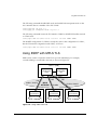
TLS VPN Configuration Examples
Basic MPLS TLS Configuration Example
Full Mesh TLS Configuration
7-10
7-11
7-12
mpls1
mpls2
mpls3
mpls4
7-13
7-13
7-13
7-13
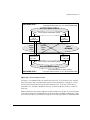
Hub and Spoke TLS Configuration
7-14
mpls1
mpls2
mpls3
mpls4
7-15
7-15
7-15
7-15
Configuration Example Using PPP Transparent Mode
Using ESRP with MPLS TLS
Tunnel Endpoint VLANs
LSP Tracking
Configuration Example
8
7-17
7-18
7-21
7-22
Configuring Destination-Sensitive Accounting
Overview of Destination-Sensitive Accounting
8-1
Basic Accounting Configuration Information
8-2
Configuring Access Profiles
Summary of Access Policy Commands
Creating an Access Profile
Configuring an Access Profile Mode
Adding an Access Profile Entry
8-3
8-3
8-5
8-6
8-6
Specifying Subnet Masks
Sequence Numbering
Permit and Deny Entries
Autonomous System Expressions
8-7
8-7
8-7
8-8
Deleting an Access Profile Entry
Removing a Routing Access Policy
8-8
8-8
Configuring Route Maps
Summary of Route Map Commands
Creating a Route Map
Adding Entries to the Route Map
Adding Statements to the Route Map Entries
viii
7-15
8-9
8-9
8-11
8-11
8-11
MPLS Module Installation and User Guide
Route Map Operation
Configuring the Accounting Bin Number for Route Map Entry
Route Map Configuration Examples
8-13
8-13
8-13
Configuring Destination-Sensitive Accounting Based on Destination IP Subnets
8-14
Configuring Destination-Sensitive Accounting Based on BGP Community
Strings
8-15
Applying the Route Map to the IP Routing Table
8-17
Displaying the Configured Route Maps for the IP Route Table
8-17
Retrieving Accounting Statistics
Using the CLI to Retrieve Accounting Statistics
Using SNMP to Retrieve Accounting Statistics
9
8-18
8-18
8-18
Additional MPLS Module Support Topics
General Switch Attributes
9-2
Image and Configuration Attributes
9-4
802.1p and 802.1Q Commands
9-4
VLAN Commands
9-5
FDB Commands
9-5
Basic IP Commands
show ipconfig Command
show iproute and rtlookup Commands
9-5
9-6
9-6
Optional show iproute Keywords
9-6
ICMP Commands
9-7
IP Multicast and Flow Redirection Commands
9-7
OSPF Commands
9-8
BGP Commands
9-8
Route Map Commands
9-8
PPP Commands
9-9
ESRP and VRRP Commands
9-9
Layer-2 and Layer-3 Switching Attributes
9-10
Debug Trace Commands
9-10
Attributes Not Directly Applicable to the MPLS Module
9-10
MPLS Module Installation and User Guide
ix
A
Supported MIBs and Standards
Standards Supported for MPLS
A-1
MIBs Supported for MPLS
A-2
Index
Index of Commands
x
MPLS Module Installation and User Guide
Preface
This preface provides an overview of this guide, describes guide conventions, and lists
other publications that may be useful.
Introduction
This guide provides the required information to install the MPLS module in a
BlackDiamond® 6800 series switch from Extreme Networks and perform the initial
module configuration tasks.
This guide is intended for use by network administrators who are responsible for
installing and setting up network equipment. It assumes a basic working knowledge of:
• Local area networks (LANs)
• Ethernet concepts
• Ethernet switching and bridging concepts
• Routing concepts
• Internet Protocol (IP) concepts
• Routing Information Protocol (RIP) and Open Shortest Path First (OSPF)
• Simple Network Management Protocol (SNMP)
If the information in the release notes shipped with your module differs from the
information in this guide, follow the release notes.
MPLS Module Installation and User Guide
xi
Terminology
Switches and switch modules that use naming conventions ending in “i” have
additional capabilities that are documented throughout this user guide. For the most
current list of products supporting the “i” chipset, consult your release notes.
Unless otherwise specified, a feature requiring the “i” chipset requires the use of both
an “i” chipset-based management module, such as the MSM64i, and an “i”
chipset-based I/O module, such as the G8Xi.
Conventions
Table 1 and Table 2 list conventions that are used throughout this guide.
Table 1: Notice Icons
Icon
Notice Type
Alerts you to...
Note
Important features or instructions.
Caution
Risk of personal injury, system damage, or loss of data.
Warning
Risk of severe personal injury.
Table 2: Text Conventions
Convention
Description
Screen displays
This typeface indicates command syntax, or represents information
as it appears on the screen.
Screen displays
bold
This typeface indicates how you would type a particular command.
The words “enter”
and “type”
When you see the word “enter” in this guide, you must type
something, and then press the Return or Enter key. Do not press the
Return or Enter key when an instruction simply says “type.”
xii
MPLS Module Installation and User Guide
Related Publications
Table 2: Text Conventions (continued)
Convention
Description
[Key] names
Key names are written with brackets, such as [Return] or [Esc].
If you must press two or more keys simultaneously, the key names
are linked with a plus sign (+). Example:
Press [Ctrl]+[Alt]+[Del].
Words in italicized type
Italics emphasize a point or denote new terms at the place where
they are defined in the text.
Related Publications
The publications related to this one are:
• ExtremeWare™ release notes
• ExtremeWare Software User Guide
• ExtremeWare Command Reference Guide
• BlackDiamond 6800 Series Switch Hardware Installation Guide
• BlackDiamond Module Installation Note
Documentation for Extreme Networks products is available on the World Wide Web at
the following location:
http://www.extremenetworks.com/
MPLS Module Installation and User Guide
xiii
xiv
MPLS Module Installation and User Guide
1
Overview
The MPLS module is a self-contained module for the BlackDiamond 6800 series
chassis-based system. Unlike other BlackDiamond modules, there are no external
network interfaces on the MPLS module. Instead, the MPLS module provides advanced
IP services for the other input/output (I/O) modules installed in the chassis. The MPLS
module contains a powerful set of packet processing resources that operate in a
one-armed fashion: receiving frames from the switch fabric, processing the frames, and
transmitting the frames back into the switch fabric.
This chapter covers the following topics:
• Summary of Features on page 1-2
• MPLS Module Physical Description on page 1-2
• BlackDiamond 6800 Series Switch Overview on page 1-5
• About the MPLS Module on page 1-6
• About MPLS on page 1-6
• About IP Unicast Forwarding on page 1-8
• About Destination-Sensitive Accounting on page 1-8
MPLS Module Installation and User Guide
1-1
Overview
Summary of Features
The MPLS module includes the following features:
• MPLS
• IP unicast forwarding (longest prefix match)
• Destination-sensitive accounting
MPLS
MultiProtocol Label Switching (MPLS) is a forwarding algorithm that uses short,
fixed-length labels to make next-hop forwarding decisions for each packet in a stream.
IP Unicast Forwarding
IP unicast packets are forwarded in the hardware using the longest prefix match
algorithm. IP unicast forwarding is required to switch packets at ingress or upon
egressing an MPLS network domain.
Destination-Sensitive Accounting
Counts of IP packets and bytes are maintained based on the IP routes used to forward
packets. Destination-sensitive accounting gives you the flexibility to bill your customers
at predetermined and different rates. The rates are based on the customers’ IP unicast
packet destinations.
The accounting feature categorizes IP unicast packets using two parameters, input
VLAN ID and accounting bin number. The VLAN ID is used to identify from which
customer the packet is received. The accounting bin number is associated with the route
used to forward the packet. External billing application servers can correlate the
accounting bin number to a specific billing rate.
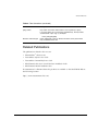
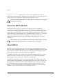
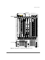
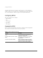
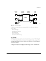
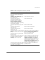
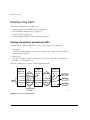
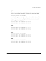
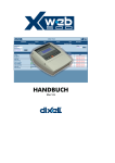
MPLS Module Physical Description
The MPLS module consists of a printed circuit board mounted on a metal carrier that
acts as the insertion vehicle in a BlackDiamond 6800 series switch. The module carrier
also includes ejector/injector handles and captive retaining screws at each end of the
module front panel. The module occupies one slot in a BlackDiamond 6800 series
1-2
MPLS Module Installation and User Guide
MPLS Module Physical Description
switch. A maximum of four MPLS modules can be placed in a BlackDiamond 6800
series switch.
Captive
retaining screw
Module status LED
Module diagnostics LED
Ejector/injector
handle
Network processors
and heat sinks
Service ports
General Purpose Processor (GPP)
PoS_002
MPLS_15
Figure 1-1: MPLS module
The MPLS module has the following key components:
• Two high-performance network processors
• A General Purpose Processor (GPP) subsystem
MPLS Module Installation and User Guide
1-3
Overview
The network processors are high-performance, programmable devices that enhance the
Extreme “i” chipset to support expanded functionality, features, and flexibility.
The GPP subsystem handles system control and MPLS module management functions.
The GPP subsystem resides outside the packet-forwarding data path to optimize
routing and billing performance.
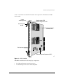
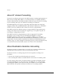
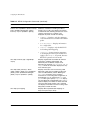
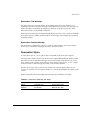
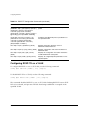
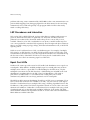
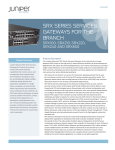
MPLS Module LED Indicators
The MPLS module is equipped with two module-level LED indicators (STATUS and
DIAG) (see Figure 1-2).
The STATUS LED indicator is located near the top end of the front panel, near the
ejector/injector handle. This LED indicator is a bi-color LED (displaying in either green
or amber) that signals the operating status of the module.
The DIAG LED indicator is located beside the STATUS LED. The LED is a bi-color LED
(displaying in either green or amber) that signals whether diagnostics are being run on
the module.
Module status LEDs
Service port
Reset
Console port
MPLS_13
Figure 1-2: Front panel view of the MPLS module
1-4
MPLS Module Installation and User Guide
BlackDiamond 6800 Series Switch Overview
Service Port
The MPLS module is equipped with one front-panel service port. The port is reserved
for use only by Extreme Networks technical support personnel for diagnostic purposes.
Console Port
The MPLS module is equipped with one front-panel serial port. The port is reserved for
use only by Extreme Networks technical support personnel for diagnostic purposes.
BlackDiamond 6800 Series Switch Overview
The BlackDiamond 6800 series switch is a chassis-based switch designed to be placed in
the core of your network. The BlackDiamond 6800 series switch is flexible and scalable,
making it easy for you to meet the changing requirements of your network. The
combination of BlackDiamond and Summit switches delivers a consistent end-to-end
network solution that provides a nonblocking architecture, wire-speed switching,
wire-speed IP routing, and policy-based Quality of Service (QoS).
About BlackDiamond Modules
In addition to the MPLS module described in this guide, the BlackDiamond 6800 series
switch supports a variety of I/O modules that offer a choice of port connections over
different media types and distances. Management Switch Fabric (MSM64i) modules
provide the internal switch fabric for data being sent between I/O modules. See the
BlackDiamond Hardware Installation Guide for more information.
BlackDiamond 6800 series MPLS modules can be inserted or removed at any time
without causing disruption of network services. No configuration information is stored
on the MPLS module; all configuration information is stored on the MSM64i module.
You can also use ExtremeWare ™ commands to configure the MPLS module after
installing it in an I/O slot in the BlackDiamond chassis, or you can preconfigure the
parameters of a module that has not yet been inserted into the chassis.
If you preconfigure a slot for a particular module, the preconfigured information is used
when the module is inserted. You must select a module type for the slot before you can
preconfigure the parameters. If you have preconfigured a slot for a specific module
type, and then insert a different type of module, you must explicitly override the
existing configuration with a new configuration, or use the ExtremeWare
MPLS Module Installation and User Guide
1-5
Overview
unconfig slot <slot> command. If you enter a new configuration for the new
module, the module uses that configuration. If you clear the slot configuration, the new
module type can use the default configuration ExtremeWare creates.
See the ExtremeWare Software User Guide for more information on configuring
BlackDiamond modules.
About the MPLS Module
The MPLS module contains a powerful set of network processors specifically
programmed to implement the MPLS function. The card has no external ports, but
contains four full-duplex gigabit Ethernet internal ports to the BlackDiamond backplane
switch fabric. Each internal processor provides media speed packet processing for two
internal full-duplex gigabit Ethernet ports. The MPLS module operates in a one-armed
fashion: receiving frames from the switch fabric, processing the frames, and
transmitting the frames back into the switch fabric to the appropriate I/O module
output port.
MPLS modules are only compatible with Inferno-series MSM modules. They are
compatible with both Inferno-series and Summit-series I/O modules.
About MPLS
MPLS is a technology that allows routers to make protocol-independent forwarding
decisions based on fixed-length labels. The use of MPLS labels enables routers to avoid
the processing overhead of delving deeply into each packet and performing complex
route lookup operations based upon destination IP addresses.
In an MPLS environment, incoming packets are initially assigned “labels” by a Label
Edge Router (LER). The labels allow the packets to be more efficiently handled by
MPLS-capable routers at each point along the forwarding path.
An MPLS label essentially consists of a short fixed-length value carried within each
packet header and that identifies a Forwarding Equivalence Class (FEC). The FEC tells
the router how to handle the packet. An FEC is defined to be a group of packets that
are forwarded in the same manner. Examples of FECs include an IP prefix, a host
address, or a VLAN ID. The label concept in MPLS is analogous to other connection
identifiers, such as an ATM VPI/VCI or a Frame Relay DLCI.
1-6
MPLS Module Installation and User Guide
About MPLS Layer-2 VPNs
By mapping to a specific FEC, the MPLS label efficiently provides the router with all of
the local link information needed for immediate forwarding to the next hop. MPLS
creates a Label Switched Path (LSP) along which each Label Switch Router (LSR) can
make forwarding decisions based solely upon the content of the labels. At each hop,
the LSR simply strips off the existing label and applies a new one that tells the next LSR
how to forward the packet.
About MPLS Layer-2 VPNs
As networks grow and become more pervasive, the need to separate the physical
network infrastructure from the logical network or VLAN organization has become
increasingly important. By logically separating the network topology from the service
provided by the physical network, services are more easily managed, reliability through
increased redundancy is improved, and you gain more efficient use of the physical
network infrastructure.
By mapping a VLAN to a specific set of MPLS tunnels, you can create virtual private
networks (VPNs). Within a VPN, all traffic is opaquely transported across the service
provider network. Each VPN can be managed and provisioned independently.
VPNs may have two or more customer points of presence (PoP). All PoPs are
interconnected using point-to-point tunnels. If there are two PoPs in the VPN, the VPN
is considered to be point-to-point. If there are more than two PoPs in the VPN, the VPN
is considered to be multipoint. Multipoint VPNs can be fully-meshed or hub-and-spoke.
Layer-2 VPNs are constructed from a set of interconnected point-to-point MPLS tunnels.
Tunnel endpoint nodes operate as virtual VPN switches, bridging traffic between
tunnels and the local egress VLAN. MAC caching is integrated into the MPLS module.
Source MAC addresses within each VPN are associated with the tunnel from which the
packet is received. Up to 256K MAC addresses can be cached. Within a VPN, once a
MAC address has been learned, unicast traffic destined to the cached MAC address is
transmitted over a single tunnel. Integrated VPN MAC caching enhancement increases
network performance and improves VPN scalability.
MPLS Module Installation and User Guide
1-7
Overview
About IP Unicast Forwarding
IP unicast forwarding is performed on the MPLS module to facilitate implementation of
MPLS and accounting. When MPLS or accounting functions are enabled, the MPLS
module, rather than the switch fabric hardware, performs layer-3 IP unicast forwarding.
Layer-2 switching and Layer-3 IP multicast forwarding are unaffected.
The MSM distributes its IP unicast routing table, ARP table, MPLS incoming label
mappings (ILMs), FEC-to-NHFLE database, and interface IP addresses to each MPLS
module so that every MPLS module contains the same IP routing database.
Each MPLS module has sufficient capacity to support 256K IP longest prefix match
lookup route entries. Each route entry also supports up to four equal-cost paths. IP
forwarding is configurable per VLAN.
Each MPLS module IP routing database provides an aggregate IP forwarding
throughput of up to 4 Gbps. The total forwarding throughput for a single
BlackDiamond chassis can be scaled up to 16 Gbps by adding up to four MPLS
modules. MPLS modules interface to the BlackDiamond switch fabric via four 1 Gbps
internal links. IP unicast traffic is internally forwarded from the BlackDiamond I/O
modules using one of three backplane load-sharing policies: port-based, address-based,
or round-robin. See the ExtremeWare Software User Guide for more information.
About Destination-Sensitive Accounting
Destination-sensitive accounting allows you to bill your customers at different rates
depending upon the destination of the IP unicast packets they send.
Destination-sensitive accounting categorizes IP unicast packets according to two
parameters:
• The ID of the VLAN from which the packet was received
• The accounting bin number associated with the route used to forward the packet
For each category, 64-bit counts of both the number of packets and number of bytes
forwarded, including those locally delivered to the MSM CPU, are collected. Eight
accounting bin numbers, with values from 0-7, are available for each of the possible
4096 VLAN IDs. This yields a maximum of 32768 sets of accounting statistics.
1-8
MPLS Module Installation and User Guide
About Destination-Sensitive Accounting
You use accounting statistics to bill your customers. For a given set of statistics, the
source VLAN ID identifies the customer and the accounting bin number corresponds to
a billing rate.
Use the ExtremeWare route-map function to configure policies that assign accounting
bin numbers to IP routes. Bin 0 is the default bin. Any route that does not have an
explicit bin assignment via the route-map function defaults to bin 0.
You retrieve accounting statistics via the command-line interface (CLI) and Simple
Network Management Protocol (SNMP).
MPLS Module Installation and User Guide
1-9
Overview
1-10
MPLS Module Installation and User Guide
2
Installing or Replacing an
MPLS Module
This chapter covers the following topics:
• Preparing for Installation on page 2-1
• Inserting and Securing a Module on page 2-6
• Verifying the Module Installation on page 2-8
• Troubleshooting on page 2-9
• Removing and Replacing an MPLS Module on page 2-14
Preparing for Installation
This section describes the preparation steps that you must perform before inserting and
securing an MPLS module. This section includes information on the following topics:
• Software and Hardware Version Requirements on page 2-2
• Safety Information on page 2-3
• Tools on page 2-4
• MPLS Module Slot Locations on page 2-4
MPLS Module Installation and User Guide
2-1
Installing or Replacing an MPLS Module
Software and Hardware Version Requirements
MPLS modules are compatible with “i” -series MSM modules, Summit and “i” -series
I/O modules, and Packet over SONET (PoS) modules. For the most current list of I/O
and PoS modules supported for use with the MPLS module, consult your release notes.
Software support for the MPLS module is provided in an ExtremeWare technology
release, which is a software release that provides specialized hardware support or
additional functionality not found in the current mainstream ExtremeWare release.
The ExtremeWare technology release that supports the MPLS module includes multiple
software packages. One software package runs on the MSM module while another
package runs on each MPLS module. You must download the software packages
independently using the ExtremeWare download image command. Each software
package has an associated version number that you can display using the show
version command. As a recommendation (not a requirement), the MSM software
package and the MPLS module software package should be the same version. To
ensure compatibility, the MSM performs an automatic compatibility check before an
MPLS module is activated. If the versions of the software packages are incompatible,
the MPLS ports on the module will not come up and the show slot command will
indicate that the software on the MPLS module is incompatible with the MSM software.
You can also verify compatibility by comparing the version of the MSM software
package with the version of the MPLS module software package. The format of the
software version field of the ExtremeWare software version identifier has been extended
to support technology releases. The following example of the ExtremeWare software
version identifier illustrates the extended version format:
ExtremeWare Version 6.1.5 (Build 20) Project IP_SERV_TECH_REL v1.2.64
In this example, the technology release-specific version information Project
IP_SERV_TECH_REL v1.2.64 is added to the base ExtremeWare version identifier
ExtremeWare Version 6.1.5 (Build 20) to form the extended version identifier format. The
first field of the version identifier, ExtremeWare Version 6.1.5 (Build 20), identifies the
ExtremeWare software version on which this technology release is based. The second
field in the extended version identifier, Project IP_SERV_TECH_REL, is the name of the
technology release. The final field 1.2.64, is a three-part number that identifies the
version of the technology release. In the example, the first part of the number, 1, is the
extended major version number; the second part of the number, 2, is the extended minor
version number; the third part of the number, 64, is the extended build version number.
2-2
MPLS Module Installation and User Guide
Preparing for Installation
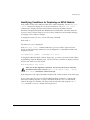
The MSM software package is compatible with the MPLS module software package
when the following conditions are true:
• Base ExtremeWare version numbers match.
• Technology release names match.
• Extended major version numbers match.
• Extended minor version number of the MSM software package is equal to or greater
than the extended minor version of the MPLS module software package.
The extended build number is ignored for compatibility comparisons.
For example, MSM software package ExtremeWare V6.1.5 (Build 20) Project
IP_SERV_TECH_REL V1.2.64 is compatible with ARM software package ExtremeWare
V6.1.5 (Build 20) Project IP_SERV_TECH_REL V1.1.98, but is not compatible with MPLS
module software package ExtremeWare V6.1.5 (Build 20) Project IP_SERV_TECH_REL
V2.1.1.
Safety Information
Before you begin the process of installing or replacing an MPLS module in a
BlackDiamond 6800 series switch, read the safety information in this section.
Failure to observe the necessary safety guidelines can lead to personal injury or
damage to the equipment.
All service components of a BlackDiamond 6800 series switch, including MPLS
modules, should be performed by trained service personnel only. Service personnel are
persons having appropriate technical training and experience necessary to be aware of
the hazards to which they are exposed in performing a task and of measures to
minimize the danger to themselves or other persons.
MPLS Module Installation and User Guide
2-3
Installing or Replacing an MPLS Module
The MPLS module uses electronic components that are sensitive to static
electricity. Electrostatic discharge (ESD) originating from you or from objects
around you can damage these components. Exercise every possible precaution
to prevent ESD when working around printed-circuit assemblies.
Keep all printed-circuit assemblies in protective ESD-preventive sacks or place
them on antistatic mats until you are ready to install them. Wear an
ESD-preventive wrist strap and ensure that the leash is securely grounded
before handling a bare circuit assembly.
Tools
You need the following tools to install an Extreme Networks MPLS module in a
BlackDiamond 6800 series chassis:
• ESD-preventive wrist strap and grounding leash that is provided with the
BlackDiamond 6800 series chassis.
• Number 1 Phillips-head screwdriver.
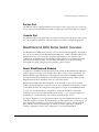
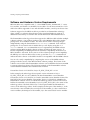
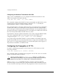
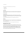
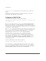
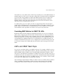
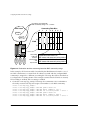
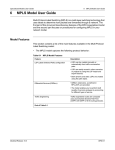
MPLS Module Slot Locations
Figure 2-1 shows the I/O module slot locations where you can insert an MPLS module
in the BlackDiamond 6808 series chassis. You can install the MPLS module in any of the
numbered slots labeled Slot 1 through Slot 8. MPLS modules do not fit in Slot A or
Slot B. When you are installing a new MPLS module, you must first remove the blank
filler from the available slot.
To ensure a sufficient flow of cooling air across the component side of the
module, install the MPLS module in the BlackDiamond 6808 series chassis so
that another module, a blank filler, or the far right chassis wall covers the
component side of the module.
2-4
MPLS Module Installation and User Guide
Preparing for Installation
MSM module
slots
I/O module slots
ESD wrist strap
connector
1
2
3
4
I/O module slots
A
B
5
50015
50015
51040
6
7
8
51032
52011
STATUS
STATUS
R
ER
G
DIA
S
TU
STA
V
EN
R
ST
M
S
SY
R
ER
V
EN
R
ST
M
S
SY
9
17
25
2
10 18
26
1
5
9
2
6
10
3
7
11
4
12
20
28
4
8
12
5
13
21
29
6
14
22
30
7
15
23
31
16
24
32
= ACTIVITY
AMBER
= LINK OK
GREEN
FLASHING GREEN = DISABLED
DIAG
DIAG
1
1
3
8
11 19
AMBER
=
ACTIVITY
27
GREEN
=
LINK OK
FLASHING
GREEN
=
DISABLED
2
1
17
1
CONSOLE
3
CONSOLE
2
3
4
20
5
21
4
4
MODEM
MODEM
5
6
MGMT
MGMT
5
8
24
9
25
6
7
LINK /
ACTIVITY
LINK /
ACTIVITY
8
7
9
12
28
13
29
10
8
11
PCMCIA
PCMCIA
12
POWER
16
32
POWER
DC OUT
DC OUT
AC IN
AC IN
50021
50021
Power supplies
V-50/60Hz
200-240V, 15A
V-50/60Hz
200-240V, 15A
BD_6808
MPLS_14
Figure 2-1: Slot locations in a BlackDiamond 6808 series chassis
MPLS Module Installation and User Guide
2-5
Installing or Replacing an MPLS Module
Inserting and Securing a Module
To insert and secure an MPLS module, follow these steps:
MPLS modules must be installed in any of the BlackDiamond 6808 chassis slots
labeled Slot 1 through Slot 8. MPLS modules do not fit in Slot A or Slot B.
Forceful insertion can damage the MPLS module.
1 Before installing modular cards into the BlackDiamond 6800 series chassis, put on
the ESD-preventive wrist strap that is provided with the chassis, and connect the
metal end of the grounding leash to the ground receptacle located on the top-left
corner of the BlackDiamond 6800 series switch front panel.
Leave the ESD-preventive wrist strap permanently connected to the BlackDiamond
6800 series chassis so that it is always available when you need to handle
ESD-sensitive switch components.
2 Identify the chassis slot for the module. If necessary, remove the blank filler from the
slot to make room for the MPLS module.
Any unoccupied module slot in the chassis should have a blank filler installed to
ensure satisfactory protection from electromagnetic interference (EMI) and to
guarantee adequate airflow through the chassis.
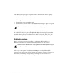
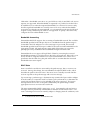
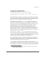
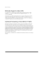
3 To insert an MPLS module, use Figure 2-2 as a reference and follow these steps:
To prevent ESD damage, handle the MPLS module by the metal card carrier
edges only. Never touch the components on the printed-circuit board or pins on
any of the connectors. Never attempt to lift or hold the module by grasping the
heat sinks on either of the network processors.
a Check to make sure that the module is right side up (printed-circuit board, or
PCB, facing to the right) and that the ejector/injector handles are extended.
b Grasp the module by its front panel with one hand and place your other hand
under the edge of the metal card carrier to support the weight of the module.
c
2-6
Slide the module into the appropriate slot of the chassis until it is fully seated in
the backplane.
MPLS Module Installation and User Guide
Inserting and Securing a Module
(a) Loosen
captive screws
1
2
3
4
A
B
50015
50015
5
6
7
8
(b) Pivot
ejector/injector
handles
POWER
POWER
DC OUT
AC IN
50020
DC OUT
AC IN
50020
PoS_0
MPLS_
Figure 2-2: Inserting and securing an MPLS module
When the module is pushed into the chassis slot, the ejector/injector
handles begin pivoting to their closed position.
d Close the ejector/injector handles by pushing them toward the center of the
module.
MPLS Module Installation and User Guide
2-7
Installing or Replacing an MPLS Module
e Use a #1 Phillips-head screwdriver to tighten the captive screw on each end of
the module front panel to prevent the module from being dislodged from the
backplane connectors and to ensure satisfactory protection from EMI.
Repeat this procedure for additional modules, if applicable.
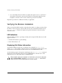
Verifying the Module Installation
After you install the MPLS module, verify that the module is working correctly. Check
the LEDs on the front panel of the module and use the command-line interface (CLI)
show slot <slot> command to display slot-specific information about the newly
installed module.
LED Indicators
When the MPLS module is operating normally, the front-panel LED indicators should
appear as follows:
• STATUS LED indicator: green blinking
• DIAG LED indicator: off
Displaying Slot Status Information
Assuming the MPLS module has no problems, the command show slot <slot>
(where <slot> is the number of the slot where you installed the module) displays that
ExtremeWare has detected the module and set it to the OPERATIONAL state.
As the module progresses through its initialization, the show slot <slot> command
displays the GPP subsystem change state to OPERATIONAL, and then each of the
network processors will change state to OPERATIONAL.
When the GPP subsystem completes its initialization cycle and the subsystem
state is OPERATIONAL, use the show diagnostics {<slot>} command to
check the results of the module power-on self test (POST).
2-8
MPLS Module Installation and User Guide
Troubleshooting
Troubleshooting
This section describes how to isolate module-specific problems and determine when it
is appropriate to remove and replace an MPLS module. This section includes
information on the following topics:
• Identifying Problem Categories on page 2-10
• Fixing Configuration Errors on page 2-11
• Upgrading the Switch Software Image on page 2-11
• Upgrading the MPLS Module Software Image on page 2-11
• Fixing Power-Related Problems on page 2-12
• Identifying Conditions for Replacing an MPLS Module on page 2-13
The information in this section should be used in conjunction with the
“Troubleshooting” appendix in the ExtremeWare Software User Guide and the
release notes that accompanied your Extreme Networks product. If you
encounter a problem that is not discussed in one of these documents, contact
Extreme Networks technical support.
MPLS Module Installation and User Guide
2-9
Installing or Replacing an MPLS Module
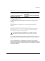
Identifying Problem Categories
Table 2-1 lists the color states of the MPLS module LEDs and describes their associated
meanings.
Table 2-1: MPLS Module LEDs
LED
Color
Indicates
Corrective action
Normal operation
No action required.
Configuration error (configured
slot type is different than inserted
module type)
See “Fixing Configuration
Errors” on page 2-11.
Version error (ExtremeWare
version does not recognize
inserted module)
See “Upgrading the Switch
Software Image” on
page 2-11.
Version error (the MPLS module
image version is not compatible
with the MSM image version)
See “Upgrading the MPLS
Module Software Image”
on page 2-11.
Hardware error (module failed
diagnostics)
See “Identifying Conditions for
Replacing an MPLS Module”
on page 2-13.
Network processor, GPP down, or
other severe card error (as
detected by network processor
heartbeat protocol)
Reboot slot. If condition
persists, run diagnostics.
Off
No power
See “Fixing Power-Related
Problems” on page 2-12.
Solid green
Normal operation
No action required.
Flashing amber
Diagnostics in progress
No action required. When
the LED goes off, use the
show diagnostics
{<slot>} command to display
test status.
Solid amber
Diagnostics failed
See “Identifying Conditions for
Replacing an MPLS Module”
on page 2-13.
STATUS Flashing green
Flashing amber
DIAG
2-10
MPLS Module Installation and User Guide
Troubleshooting
Fixing Configuration Errors
If the STATUS LED on the MPLS module turns amber and blinks, use the show slot
<slot> command to display the configured slot type. The output from this command
also displays information about the module state, including the card mismatch message.
This message indicates that the slot was previously configured for a module type
different than the one you just installed.
Use one of the following commands to reset the slot configuration:
•
clear slot <slot>
•
unconfig slot <slot>
•
config slot <slot> module mpls
The first two commands listed here, clear the slot of a previously assigned
module type. The third command replaces the existing module type configuration
with a new module type configuration.
Upgrading the Switch Software Image
If the STATUS LED on the MPLS module turns amber and blinks, use the
show slot <slot> command to display the configured slot type. The output from this
command also displays information about the module state, including the card
unknown message. This message indicates that the installed ExtremeWare software
image version does not recognize the module type.
To correct this problem, you need to upgrade the ExtremeWare software image. To
perform this task, see the “Software Upgrade and Boot Options” chapter in the
ExtremeWare Software User Guide.
To verify the ExtremeWare technology release that supports the MPLS module,
consult the release notes that shipped with your product.
Upgrading the MPLS Module Software Image
The MPLS module software image file contains the executable code that runs on the
MPLS module. The file is preinstalled on the MPLS module at the factory. As new
versions of the image are released, they can be downloaded to the MPLS module.
When you upgrade the MPLS module software image, you might also be
required to upgrade the image for associated MSM modules to maintain software
compatibility.
MPLS Module Installation and User Guide
2-11
Installing or Replacing an MPLS Module
To download an MPLS module software image, use the following command:
download image [<ipaddress> | <hostname> | <filename> {primary |
secondary} slot <slot>
The download command verifies that the new code image is compatible with the
card inserted into the specified slot. If the image is not compatible, the download
is aborted.
This command is the same command used to download ExtremeWare software images
to MSM modules, but you use the slot <slot> option to download the specified
image file to the MPLS module in the specified slot rather than to the primary or
secondary switch partitions.
Like the MSM module, the MPLS module can store up to two images: a primary and a
secondary image. When you download a new image, you must specify the
space—primary or secondary—where the new image is to be stored. If you do not
specify the image space, the new image is downloaded to the image space that is used
as the load source on the next reboot.
To select which image—primary or secondary—the MPLS module loads on the next
reboot, use the following command:
use image [primary | secondary] {slot <slot>}
Fixing Power-Related Problems
If the LEDs on all other modules are off, verify that the BlackDiamond 6800 series
switch is connected to an appropriate power source and is turned on.
If the LEDs on the new module are off, but the LEDs on other modules are on, try
ejecting and reseating the unpowered module. If the module still does not power up, it
is possible that the available system power is not sufficient to handle the burden of the
added module. To test this condition, temporarily eject an I/O module to see whether
that frees enough power to power up the new card. If it does, you may need to upgrade
the power supply configuration in this BlackDiamond 6800 series switch. See the
BlackDiamond 6800 Series Switch Hardware Installation Guide for more information.
2-12
MPLS Module Installation and User Guide
Troubleshooting
Identifying Conditions for Replacing an MPLS Module
If the STATUS LED on the MPLS module turns amber and blinks, use the show slot
<slot> command to display the slot status information. The show slot <slot>
command also displays operational information related to the MPLS module.
Information displayed includes the BlackDiamond switch fabric card state, Network
Processor status, General Purpose Processor status, hardware serial number and type,
and image version and boot settings.
To display the status for slot 1, use the following command:
show slot 1
The status for slot 1 is displayed.
If the show slot <slot> command indicates a processor failure (state will show
down), use the following command to run the diagnostics on the MPLS module and
display the results:
run diagnostics [normal | extended] slot <slot>
To display the MPLS module software diagnostics, you must wait for the DIAG LED to
stop blinking. After the blinking stops, use the following command to display each test
that was run with a Pass/Fail status:
show diagnostics slot <slot>
After you run the diagnostics command, the slot must be reset to reload the
operational code image. Use the reboot {time <date> <time> | cancel}
slot <slot> command to reload the image.
If the diagnostics fail, replace the MPLS module with another module of the same type.
If one of the network processors fails, the MPLS module continues to operate with
reduced forwarding capacity. As long as the MPLS module is not over subscribed,
network disruption is minimal. The entire card must be rebooted using the reboot
slot command to recover a halted network processor.
MPLS Module Installation and User Guide
2-13
Installing or Replacing an MPLS Module
Removing and Replacing an MPLS Module
MPLS modules can be installed in any of the BlackDiamond 6808 chassis slots labeled
Slot 1 through Slot 8. MPLS module do not fit in Slot A or Slot B. Forceful insertion can
damage the MPLS module.
The MPLS module can be extracted from or inserted into the BlackDiamond
6808 chassis at any time without disrupting network services.
Tools and Equipment
You need the following items to remove and replace an MPLS module:
• ESD-preventive wrist strap
• Number 1 Phillips-head screwdriver
• Replacement MPLS module
Removing an MPLS Module
To remove an MPLS module, follow these steps:
1 Put on the ESD-preventive wrist strap that is provided with the chassis, and verify
that the metal end of the leash is connected to the ground receptacle located on the
top-left corner of the BlackDiamond 6800 series switch front panel.
2 Identify the MPLS module to be replaced and write down the following information
for later use:
— The chassis slot number. When you install the replacement MPLS module, install
it in the same chassis slot.
3 Use the #1 Phillips-head screwdriver to loosen the captive screw at each end of the
MPLS module front panel.
4 Grasp both ejector/injector handles and pivot them simultaneously away from each
other to unseat the module from the chassis backplane.
5 Use the ejector/injector handles to pull the module part way out of the chassis slot.
Do not touch the printed-circuit board or any connector pins.
An EMI-preventive gasket is attached to one edge of the module front panel. To
prevent diminished EMI protection, handle the module carefully and avoid
damage to this gasket.
2-14
MPLS Module Installation and User Guide
Removing and Replacing an MPLS Module
6 Grasp the module front panel with one hand and place your other hand under the
metal card carrier to support the weight of the module. Slide the module completely
out of the chassis slot. Place the module immediately into an antistatic sack to
protect it from ESD damage and prevent dust from collecting on the module’s
optical fiber connectors.
7 Install and secure the replacement module. See “Inserting and Securing a Module”
on page 2-6 for more details.
MPLS Module Installation and User Guide
2-15
Installing or Replacing an MPLS Module
2-16
MPLS Module Installation and User Guide
3
Configuring the MPLS Module
This chapter describes general information about MPLS and the ExtremeWare
commands that support the MPLS module. Other commands and background
information used to configure I/O modules and switch behavior in a network are
documented in the ExtremeWare Software User Guide. For hardware installation
information for the BlackDiamond 6800 series switch, see the BlackDiamond Hardware
Installation Guide.
Documentation for Extreme Networks products is available at the Extreme
Networks home page at http://www.extremenetworks.com/.
This chapter covers the following topics:
• Overview of MPLS on page 3-1
• MPLS Layer on page 3-8
• Configuring MPLS on page 3-12
Overview of MPLS
MultiProtocol Label Switching (MPLS) encompasses a growing set of protocols defined
by the IETF. True to its name, MPLS is based on a label-switching forwarding algorithm.
ATM and Frame Relay are examples of other protocols that use label-switching
forwarding algorithms.
MPLS Module Installation and User Guide
3-1
Configuring the MPLS Module
Conceptually, label switching is straightforward. A label is a relatively short,
fixed-length identifier that is used to forward packets received from a given link. The
label value is locally significant to a particular link and is assigned by the receiving
entity.
Because labels are relatively short (for example, 20 bits in a MPLS shim header), the
label of a received packet can be used as an index into a linear array containing the
forwarding database. Forwarding database entries indicate the outgoing port and any
label(s) to be applied to forwarded frames. Thus, forwarding may consist of a simple
lookup and replacement of the incoming label with the appropriate outgoing label
(otherwise known as label swapping).
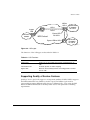
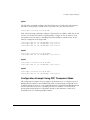
Figure 3-1 illustrates an MPLS network.
Egress
LER
Ingress
LER
Destination IP
network
LSR
Source IP
network
LSR
LSP
MPLS cloud
MPLS_05
Figure 3-1: MPLS network
MPLS Terms and Acronyms
Table 3-1 defines common MPLS terms and acronyms.
Table 3-1: MPLS Terms and Acronyms
Term or Acronym
Description
CSPF
Constrained Shortest Path First. Route selection determined by an
algorithm based on available link bandwidth and path cost.
DoD
Downstream-on-Demand. Distribution of labels as a result of explicit
upstream label requests.
3-2
MPLS Module Installation and User Guide
Overview of MPLS
Table 3-1: MPLS Terms and Acronyms (continued)
Term or Acronym
Description
DU
Downstream Unsolicited. Distribution of labels downstream without an
explicit label request.
FEC
Forward Equivalence Class. A group of packets that are forwarded in
the same manner (for example, over the same Label Switched Path).
Label
A short, fixed-length identifier used to forward packets from a given
link.
Label stack
A set of one or more MPLS labels used by MPLS to forward packets
to the appropriate destination.
Label swapping
Lookup and replacement of an incoming label with the appropriate
outgoing label.
LDP
Label Distribution Protocol. A protocol defined by the IETF used to
establish an MPLS Label Switched Path (LSP).
LER
Label Edge Router. A Label Switch Router that is at the beginning
(ingress) or end (egress) of a Label Switched Path.
LSP
Label Switched Path. The unidirectional MPLS connection between
two routers over which packets are sent.
LSR
Label Switch Router. A router that receives and transmits packets on
an MPLS network.
MPLS
MultiProtocol Label Switching. A set of protocols defined by the IETF
used to transmit information based on a label-switching forwarding
algorithm.
NHLFE
Next Hop Label Forwarding Entry. The NHLFE represents the MPLS
router next hop along the LSP.
PHP
Penultimate Hop Popping. A label stack optimization used for
conserving the number of allocated labels.
RSVP
Resource ReSerVation Protocol. A resource setup protocol designed
for an integrated services network.
RSVP-TE
The combination of RSVP and MPLS label signaling to provide traffic
engineered LSPs as specified in draft-ietf-mpls-rsvp-lsp-tunnel-09.txt.
Shim header
MPLS-specific header information that is inserted between layer-2
and layer-3 information in the data packet.
SP
Service Provider. An entity that provides network services for
individuals or organizations.
TE
Traffic Engineering. The provisioning of an autonomous flow along a
specified network path.
TLS
Transparent LAN Services. A method for providing layer-2 virtual
private networks (VPNs).
MPLS Module Installation and User Guide
3-3
Configuring the MPLS Module
Table 3-1: MPLS Terms and Acronyms (continued)
Term or Acronym
Description
TLS Tunnel
A specific type of VC tunnel that carries only VLAN tagged Ethernet
traffic.
Tunnel LSP
Any active RSVP-TE LSP used to forward IP traffic through an MPLS
network.
VC
Virtual Circuit. A logical point-to-point connection.
VC Tunnel
A two label stack LSP used to tunnel a specific type of traffic. The
type of traffic carried over the VC tunnel is negotiated when VC
tunnel is established.
VPLS
Virtual Private LAN Services. A multipoint Layer-2 VPN service
that has the property that all VC tunnels within a VPN are
signaled with the same vcid, where the vcid represents the
VPN identifier.
VPN
Virtual Private Network. A logical private network domain that spans
a public or service provider network infrastructure.
Label Switched Paths
Protocols that use label switching are connection-oriented. In MPLS, the connections are
called Label Switched Paths (LSPs) and are unidirectional in nature.
LSPs are established using the LDP or RSVP-TE. Once established, an LSP can be used
to carry IP traffic or to tunnel other types of traffic, such as bridged MAC frames. The
tunnel aspects of LSPs, which are important in supporting virtual private networks
(VPNs), result from the fact that forwarding is based solely on labels and not on any
other information carried within the packet.
Label Advertisement Modes
MPLS provides two modes for advertising labels:
• Downstream-on-demand (DoD)
• Downstream unsolicited (DU)
Using DoD mode, label bindings are only distributed in response to explicit requests. A
typical LSP establishment flow begins when the ingress LER originates a label request
message to request a label binding for a particular FEC (for a particular IP address
prefix or IP host address). The label request message follows the normal routed path to
the FEC. The egress LER responds with a label mapping message that includes a label
3-4
MPLS Module Installation and User Guide
Overview of MPLS
binding for the FEC. The label mapping message then follows the routed path back to
the ingress LSR, and a label binding is provided by each LSR along the path. LSP
establishment is complete when the ingress LER receives the label mapping message.
Conversely, using DU mode, an LSR may distribute label bindings to LSRs that have
not specifically requested them. These bindings are distributed using the label mapping
message, as in downstream-on-demand mode. From an LDP message perspective, the
primary difference using DU mode is the lack of a preceding label request message.
Architecturally, the difference is more significant, because the DU mode is often
associated with a topology-driven strategy, where labels are routinely assigned to
entries as they are inserted into the routing database. In either case, an LSR only uses a
label binding to switch traffic if the binding was received from the current next hop for
the associated FEC.
Both label advertisement modes can be concurrently deployed in the same network.
However, for a given adjacency, the two LSRs must agree on the discipline. Negotiation
procedures specify that DU mode be used when a conflict exists. Label request
messages can still be used when MPLS is operating in unsolicited mode.
The Extreme LDP implementation supports DU mode only. RSVP-TE, by definition, is
DoD.
Label Retention Modes
MPLS provides two modes for label retention:
• Conservative
• Liberal
Using conservative label retention mode, an LSR retains only the label-to-FEC mappings
that it currently needs (mappings received from the current next hop for the FEC).
Using liberal retention mode, LSRs keep all the mappings that have been advertised to
them. The trade-off is memory resources saved by conservative mode versus the
potential of quicker response to routing changes made possible by liberal retention (for
example, when the label binding for a new next hop is already resident in memory).
The Extreme MPLS implementation supports liberal label retention, only.
MPLS Module Installation and User Guide
3-5
Configuring the MPLS Module
LSP Control Modes
MPLS provides two LSP control modes:
• Independent
• Ordered
Using independent LSP control, each LSR makes independent decisions to bind labels
to FECs. By contrast, using ordered LSP control, the initial label for an LSP is always
assigned by the egress LSR for the associated FEC (either in response to a label request
message or by virtue of sending an unsolicited label mapping message).
More specifically, using ordered LSP control, an LSR only binds a label to a particular
FEC if it is the egress LSR for the FEC, or if it has already received a label binding for
the FEC from its next hop for the FEC. True to its name, the mode provides a more
controlled environment that yields benefits such as preventing loops and ensuring use
of consistent FECs throughout the network.
The Extreme MPLS implementation supports ordered LSP control, only.
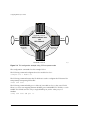
Label Switch Routers
MPLS protocols are designed primarily for routed IP networks and are implemented by
Label Switch Routers (LSRs). The router where an LSP originates is called the ingress LSR,
while the router where an LSP terminates is called the egress LSR.
Ingress and egress LSRs are also referred to as Label Edge Routers (LERs). For any
particular LSP, a router is either an ingress LER, an intermediate LSR, or an egress LER.
However, a router may function as an LER for one LSP, while simultaneously function
as an intermediate LSR for another LSP.
Figure 3-2 illustrates the three types of LSRs.
3-6
MPLS Module Installation and User Guide
Overview of MPLS
LSR for
LSP A
LSP A
Ingress
LER
Source IP
network
LSP B
LSR
MPLS cloud
Destination
IP network
for LSP B
Egress LER
for LSP B
Egress LER for LSP A
Destination
IP network
for LSP A
MPLS_12
Figure 3-2: LSR types
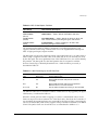
The functions of the LSR types are described in Table 3-2.
Table 3-2: LSR Functions
LSR
Function
Ingress LER
Inserts one or more labels into packets transmitted onto an
LSP.
Intermediate LSR
Forwards packets via label swapping.
Egress LER
Removes the last label(s) before forwarding packets received
from an LSP.
Supporting Quality of Service Features
Quality of Service (QoS) LSP support is an important attribute of MPLS. MPLS supports
the Differentiated Services (DiffServ) model of QoS. The DiffServ QoS model is
supported by mapping different traffic classes to different LSPs, or by using the EXP
bits in the MPLS shim header to identify traffic classes with particular forwarding
requirements.
MPLS Module Installation and User Guide
3-7
Configuring the MPLS Module
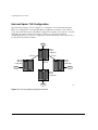
MPLS Layer
MPLS can be thought of as a shim-layer between layer 2 and layer 3 of the protocol
stack. MPLS provides connection services to layer-3 functions while making use of
link-layer services from layer-2. To achieve this, MPLS defines a shim header that is
inserted between the link layer header and the network layer header of transmitted
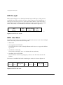
frames. The format of a 32-bit MPLS shim header is illustrated in Figure 3-3.
Label
(20 bits)
EXP
(3 bits)
bottom-of-stack
(1 bits)
TTL
(8 bits)
MPLS_01
Figure 3-3: MPLS shim header
MPLS Label Stack
The MPLS shim header is also referred to as a label stack, because it can contain multiple
entries. Each entry contains the following fields:
• 20-bit label
• 3-bit experimental (EXP) field
The EXP field can be used to identify different traffic classes to support the DiffServ
QoS model.
• 1-bit bottom-of-stack flag
The bottom-of-stack bit is set to 1 to indicate the last stack entry.
• 8-bit Time-To-Live (TTL) field.
The TTL field is used for loop mitigation, similar to the TTL field carried in IP
headers.
The format of an MPLS label stack containing two entries is shown in Figure 3-4.
Label 1
EXP
bottom-of-stack
=0
TTL
Label 2
EXP
bottom-of-stack
=1
TTL
MPLS_02
Figure 3-4: MPLS label stack
3-8
MPLS Module Installation and User Guide
MPLS Layer
Figure 3-5 illustrates the format of a unicast MPLS frame on an Ethernet link. The MAC
addresses are those of the adjacent MPLS router interfaces. The x8847 Ethertype value
indicates that the frame contains a MPLS unicast packet. A different Ethertype value
(x8848) is used to identify MPLS multicast packets.
MAC DA
MAC SA
Ethertype
x8847
MPLS
label stack
remainder
of frame
MPLS_03
Figure 3-5: MPLS unicast frame on Ethernet
Figure 3-6 shows the format of a unicast MPLS frame that contains an 802.1Q VLAN
tag. In both cases, the Ethertype values no longer identify the network layer protocol
type. This implies that, generally, the protocol type must be inferable from the MPLS
label value(s). For example, when only one type of protocol is carried on a given LSP.
MAC DA
MAC SA
Ethertype
x8100
VLAN tag
Ethertype
x8847
MPLS
label stack
remainder
of frame
MPLS_04
Figure 3-6: MPLS unicast frame on tagged Ethernet VLAN
The approach of the shim header encapsulation is similar for Packet over SONET (PoS)
interfaces running PPP. For PoS interfaces running PPP, the MPLS shim header follows
the PPP Protocol ID (PID) field. A PID of x0281 is used to indicate MPLS unicast, while
a PID of x0283 identifies MPLS multicast.
MPLS can also take advantage of technologies that can carry labels in the link layer
header. For example, MPLS labels can be carried in the VPI/VCI fields of ATM cell
headers. Frame Relay provides another example; an MPLS label can be carried in the
DLCI field.
For more detailed information on MPLS encapsulations, see RFC 3032, MPLS
Label Stack Encoding.
MPLS Module Installation and User Guide
3-9
Configuring the MPLS Module
Penultimate Hop Popping
Penultimate hop popping (PHP) is an LSR label stack processing optimization feature.
When enabled, the LSR can “pop” (or discard) the remaining label stack and forward
the packet to the last router along the LSP as a normal Ethernet packet.
By popping the label stack one hop prior to the LSP egress router, the egress router is
spared having to do two lookups. After the label stack has been popped by the
penultimate hop LSR, the LSP egress router must only perform an address lookup to
forward the packet to the destination.
PHP label advertisements using implicit NULL labels can be optionally enabled.
Support for receiving implicit NULL label advertisements by neighbor LSRs is always
enabled. For example, if an LSR advertises implicit NULL labels for IP prefixes, the
neighbor LSRs must support PHP.
Label Binding
Label binding is the process of, and the rules used to, associate labels with FECs. LSRs
construct label mappings and forwarding tables that comprise two types of labels: labels
that are locally assigned and labels that are remotely assigned.
Locally assigned labels are labels that are chosen and assigned locally by the LSR. For
example, when the LSR assigns a label for an advertised direct interface. This binding
information is communicated to neighboring LSRs. Neighbor LSRs view this binding
information as remotely assigned.
Remotely assigned labels are labels that are assigned based on binding information
received from another LSR.
Label Space Partitioning
The Extreme MPLS implementation supports approximately 64 K locally-assigned
labels. The label space is partitioned as described in Table 3-3.
3-10
MPLS Module Installation and User Guide
MPLS Layer
Table 3-3: MPLS Label Space Partitions
Label Range
Label Partition Description
x00000-x0000F
Defined/reserved by MPLS standards specified in RFC 3032.
x00010-x0BBFF
(48,112)
LSR Partition — Used to identify intermediate LSR LSPs.
x8C000-x8FFFF
(16,384)
TLS LER Partition — Used to identify the VLAN for which TLS
traffic is destined when performing the egress LER function.
xCBC00-xCBFFF
(1024)
IP LER Partition — Used for mappings to IP FECs when
performing the egress LER function.
The partitioning described in Table 3-3 maximizes forwarding performance, and
supports efficient load sharing of MPLS traffic across the Gigabit Ethernet backplane
links of high-speed input/output modules.
The data path uses the least significant 16 bits of the label (bits 0-15) as an index when a
label lookup is required. The next 2 bits of the label (bits 16-17) are currently not used
by the data path. The most significant 2 bits of the label (bits 18-19) are used to identify
the partition. The data path uses the label partition bits in conjunction with the
bottom-of-stack flag to efficiently determine how a label should be processed, as
described in Table 3-4.
Table 3-4: Label Processing by the NP Data Path
Partition
Bottom-of-stack
Label Processing
LSR
Don’t Care
Perform label lookup.
IP
Yes
Remove MPLS header and perform normal IP
forwarding.
TLS
Yes
Remove MPLS header and parse encapsulated
Ethernet frame as if it were received.
IP or TLS
No
Pop the label and repeat processing on the next label.
The MPLS module does not limit the number of labels that can be popped by the egress
LSR function, as indicated in Table 3-4.
When the switch performs label swapping as a transit or intermediate LSR, no hard
limits are imposed on the maximum size of the label stack, other than the constraint of
not exceeding the maximum frame size supported by the physical links comprising the
LSP. You should enable jumbo frame support on the ports that are members of an MPLS
VLAN. The jumbo frame size should be set to accommodate the addition of a
MPLS Module Installation and User Guide
3-11
Configuring the MPLS Module
maximally-sized label stack. For example, a jumbo frame size of at least 1530 bytes is
needed to support a two-level label stack on a tagged Ethernet port and a jumbo frame
size of at least 1548 bytes is needed to support a TLS encapsulated MPLS frame.
Configuring MPLS
This section describes how to configure:
• MPLS interfaces
• LDP
• OSPF support
• QoS support
• Filter support
Commands for MPLS
Table 3-5 describes the ExtremeWare commands for configuring and monitoring MPLS.
Each command is described in detail in the sections that follow.
Table 3-5: MPLS Configuration Commands
Command
Description
config mpls add vlan [<name> | all] {ldp |
rsvp-te}
Enables LDP or RSVP-TE for one or all VLANs.
If not specified, both LDP and RSVP-TE are
enabled on the specified VLAN.
config mpls delete vlan [<name> | all] {ldp |
rsvp-te}
Disables LDP or RSVP-TE on one or all VLANs.
If not specified, both are disabled for the
specified VLAN.
config mpls php [enabled | disabled]
Enables and disables penultimate hop popping
(PHP) at the egress LSR. When enabled, PHP is
requested on all LSPs for which the switch is the
egress LSR. The default setting is disabled.
3-12
MPLS Module Installation and User Guide
Configuring MPLS
Table 3-5: MPLS Configuration Commands (continued)
Command
Description
config mpls propagate-ip-ttl [enabled |
disabled]
Enables or disables the propagation of the IP
time-to-live (TTL) field for routed IP packets.
Specify one of the following:
config mpls qos-mapping [dot1p-to-exp |
exp-to-dot1p] [all |
<input_value>]/<output_value>
■
enabled — Each LSR is viewed as a router
hop from an IP TTL perspective.
■
disabled — The LSP is viewed as a
point-to-point link between the ingress LSR
and the egress LSR.
Configures MPLS-specific QoS mappings.
Specify one of the following QoS mappings:
■
dot1p-to-exp — Mappings are used in
performing the ingress LSR function. The
value in this priority field is set based on the
QoS classification performed by the ingress
I/O module.
■
exp-to-dot1p — Mappings are used when
performing label swapping as an intermediate
LSR and when performing the egress LSR
function.
config mpls vlan [<name> | all] ip-mtu
<number>
Configures the IP MTU for frames transmitted
onto MPLS LSPs via the specified egress VLAN.
The range is 42 to 9190 (using jumbo frame
sizes). The default setting is 4 less than the IP
MTU value. By default, the IP MTU value is 1500
bytes, so the default MPLS MTU is 1496 bytes.
disable mpls
Disables MPLS on the switch. Disabling MPLS
causes all LSPs to be released and all LDP
neighbor sessions to be terminated.
enable mpls
Enables MPLS on the switch. By default, MPLS
is disabled.
show mpls {vlan <name>} {detail}
Displays MPLS configuration information for one
or all VLANs. Omitting the vlan keyword,
displays information for all VLANs.
MPLS Module Installation and User Guide
3-13
Configuring the MPLS Module
Table 3-5: MPLS Configuration Commands (continued)
Command
Description
show mpls forwarding {summary | detail |
Displays information from the FEC-to-NHLFE
inactive | host <ipaddress> {detail | inactive} | database, used when forwarding non-MPLS
prefix <ipaddress/masklength> {detail |
packets onto an LSP. Also displays information
inactive} | rsvp-te <ipaddress> {detail}}
for RSVP-TE LSPs. Omitting all keywords causes
summary information for all FECs to be
displayed. Keywords include the following:
• summary — Displays only the summary
route information associated with labeled
paths.
• host or prefix — Display information
for a single FEC.
• rsvp-te — Displays only the RSVP-TE
forwarding label mapping.
• inactive — Causes inactive mappings
to be displayed. This keyword does not
apply to the rsvp-te keyword, because
RSVP-TE operates in DoD mode.
show mpls interface {ldp | targeted-ldp |
rsvp-te}
Displays targeted LDP and RSVP-TE interface
information, including targeted LDP and
RSVP-TE peer IP address and peer state.
Specifying the keyword ldp, targeted-ldp, or
rsvp-te limits the information displayed to only
those interface types.
show mpls label {summary | detail |
<label_number> {detail} | host <ipaddress>
{detail} | prefix <ipaddress/masklength>
{detail} | rsvp-te <ipaddress> {detail}}
Displays information from the Incoming Label
Map (ILM), used when forwarding packets that
arrive as labeled MPLS packets. Omitting the
hex_label parameter causes summary
information for all incoming label assignments to
be displayed. You can specify both host and
prefix FEC types. Specify rsvp-te to display
only the RSVP-TE assigned labels.The summary
keyword displays the number of labels allocated
from each label range partition. This command
also displays information from the Incoming Label
Map (ILM) for RSVP-TE LSPs.
show mpls qos-mapping
Displays MPLS-specified QoS mappings for
dot1p-to-exp and exp-to-dot1p.
3-14
MPLS Module Installation and User Guide
Configuring MPLS
Table 3-5: MPLS Configuration Commands (continued)
Command
Description
unconfig mpls
Resets MPLS configuration parameters to the
default settings.
unconfig mpls qos-mapping [dotp-to-exp |
exp-to-dot1p | lsp <lsp_name>]
Restores the default values for the specified QoS
mapping table.
Configuring Interfaces
To configure MPLS interfaces, first enable MPLS on the router using the following
command:
enable mpls
Next, enable MPLS on a specific VLAN or on all VLANs, using the following
command:
config mpls add vlan [<name> | all] {ldp | rsvp-te}
MPLS must be enabled on all VLANs that transmit or receive MPLS-encapsulated
frames. Using the config mpls add vlan command causes the LDP neighbor
discovery process to begin on the specified VLAN.
The specified VLAN must be configured with an IP address, and have IP
forwarding enabled. IGMP snooping must also be enabled on the switch.
If all VLANs are selected, MPLS is enabled on all VLANs that have an IP address and
IP forwarding enabled. This command optionally enables LDP or RSVP-TE for the
specified VLAN. If not specified, both LDP and RSVP-TE are enabled on the specified
VLAN.
If you have enabled MPLS on an OSPF interface that is used to reach a particular
destination, make sure that you enable MPLS on all additional OSPF interfaces that can
reach that same destination (for example, enable MPLS on all VLANs that are connected
to the backbone network).
MPLS Module Installation and User Guide
3-15
Configuring the MPLS Module
Configuring the Maximum Transmission Unit Size
After you have enabled MPLS, you can configure the maximum transmission unit
(MTU) size using the following command:
config mpls vlan [<name> | all] ip-mtu <number>
This command configures the IP MTU for frames transmitted onto MPLS LSPs via the
specified egress VLAN. The default settings is 1496 bytes. If all is selected, the
configuring MTU applies to all MPLS-enabled VLANs.
This command applies to the ingress LSR only when a received IP packet is destined for
an MPLS LSP. In this case, if the length of the IP packet exceeds the configured MTU
size for the egress VLAN and the Don’t Fragment (DF) bit is not set in the IP header of
the packet, the packet is fragmented before it is forwarded onto an MPLS LSP. If the DF
bit is set in the packet header, Path MTU Discovery starts.
Fragmentation is based on either the minimum value of the configured MPLS IP MTU
size or the configured IP MTU size for the egress VLAN. (The IP MTU size is
configured using the config ip-mtu <number> vlan <name> command.)
You should configure the MPLS IP MTU so that the addition of the MPLS label stack
the link layer header does not cause the packet to be too large to be transmitted on the
egress ports. To avoid potential problems, you should enable jumbo frame support on
all ports that are members of an MPLS VLAN.
Configuring the Propagation of IP TTL
To enable or disable the propagation of the IP time-to-live (TTL) function, use the
following command:
config mpls propagate-ip-ttl [enabled | disabled]
This command enables and disables the propagation of the IP TTL value for routed IP
packets. The default setting is enabled.
You must maintain identical propagate-ip-ttl settings on all LERs in the
MPLS domain. Not doing so may cause packets to loop endlessly and not be
purged from the network if a routing loop is inadvertently introduced.
When propagate-ip-ttl is disabled, the LSP is viewed as a point-to-point link
between the ingress LSR and the egress LSR. Intermediate LSRs in the MPLS network
are not viewed as router hops (from an IP TTL perspective). In this case, the IP TTL is
3-16
MPLS Module Installation and User Guide
Configuring MPLS
decremented once by the ingress LSR and once by the egress LSR. When disabled, the
MPLS TTL is set to 255 by the ingress LSR and is independent of the IP TTL.
When propagate-ip-ttl is enabled, each LSR is viewed as a router hop (from an IP
TTL perspective). When a packet traverses an LSP, it emerges with the same TTL value
that it would have had if it had traversed the same sequence of routers without being
label-switched. When enabled, the MPLS TTL field is initially set by the IP TTL field at
the ingress LSR, and the IP TTL field is set to the MPLS TTL by the egress LSR.
Configuring Penultimate Hop Popping
To enable or disable PHP, use the following command:
config mpls php [enabled | disabled]
This command enables or disables whether PHP is requested by the egress LER.
When PHP is enabled, PHP is requested on all LSPs for which the switch is the egress
LER.
PHP is requested by assigning the Implicit Null Label in an advertised mapping. PHP is
always performed when requested by an egress LSR (for example, when the switch is
acting as an intermediate LSR). The Implicit Null Label is always used in conjunction
with routes exported by OSPF, regardless of the PHP configuration.
This command can only be executed when MPLS is disabled. The default setting is
disabled.
Configuring QoS Mappings
To configure QoS mappings, use the following command:
config mpls qos-mapping [dot1p-to-exp | exp-to-dot1p] [all |
<input_value>]/<output_value>
This command configures MPLS QoS mappings. If all is specified, all input values are
mapped to the specified <output_value>. The valid range of integers for the
<input_value> and the <output_value> is 0 to 7. By default, the mapping tables are
initialized such than an <input_value> of n is mapped to an <output_value> of n.
MPLS Module Installation and User Guide
3-17
Configuring the MPLS Module
Two mappings are supported:
• dot1p-to-exp
• exp-to-dot1p
Dot1p-to-exp Mappings
The dot1p-to-exp mappings are used by the ingress LSR. When a non-MPLS ingress
frame arrives at the MPLS module, the frame always contains an IEEE 802.1p priority
field.
The value of the priority field is set based on the QoS classification performed by the
ingress I/O module. The ingress I/O modules assign each packet to a hardware queue,
based on the configured ExtremeWare QoS policies. There is a one-to-one mapping
between the hardware queue and the 802.1p priority values that are inserted into
frames forwarded to the MPLS module. For example, the 802.1p priority value is set to
0 for frames forwarded from hardware queue 0, set to 1 for frames forwarded from
hardware queue 1, and so on.
The dot1p-to-exp table maps 802.1 priority values to MPLS EXP values. The table is
completely flexible, such that any 802.1p priority <input_value> can be mapped to any
EXP <output_value>. The EXP output_value is set in the MPLS header of the packet as
it is forwarded to the MPLS network.
Exp-to-dot1p Mappings
The exp-to-dot1p mappings are used when the switch performs label swapping as an
intermediate LSR and when the switch is the egress LSR. In both of these cases, the
MPLS module receives an MPLS-encapsulated frame.
The EXP field in the frame is used as an <input_value> to the exp-to-dot1p table. The
corresponding <output_value> is an 802.1p priority value. The 802.1p priority value is
inserted into the frame before the frame is forwarded by the MPLS module.
The exp-to-dot1p table is completely flexible, such that any EXP <input_value> can be
mapped to any 802.1p priority <output_value>.
The exp-to-dot1p table is also used by Packet over SONET (PoS) ports when classifying
MPLS-encapsulated packets received from the SONET link. When a PoS port receives
an MPLS-encapsulated packet from the SONET link, the packet is classified based on
the EXP value in the MPLS shim header. The EXP value from the received frame is used
as an index into the exp-to-dot1p mapping table to retrieve and 802.1p priority value.
3-18
MPLS Module Installation and User Guide
Configuring MPLS
The frame is then assigned to a QoS profile, based on the retrieved 802.1p priority
value. The mappings between 802.1p priority values and QoS profiles are configured
using the following command:
config dot1p type
For more information on QoS, see the ExtremeWare Software User Guide. For
more information on the PoS module, see the PoS Module Installation and User
Guide.
Resetting MPLS Configuration Parameter Values
To reset MPLS configuration parameters to their default values, use the following
command:
unconfig mpls
This command resets the following configuration parameters:
• IP-MTU
• LDP propagation filter settings on all VLANs
• LDP advertisement filter settings
• LDP session timers
• RSVP-TE interface parameters
• RSVP-TE profile parameters
• Settings for propagate-ip-ttl
• QoS mapping tables
To restore the default values for the QoS mapping tables, use the following command:
unconfig mpls qos-mapping [dot1p-to-exp | exp-to-dot1p]
The default contents of either QoS mapping table maps an input value of n to an output
value of n.
MPLS Module Installation and User Guide
3-19
Configuring the MPLS Module
Displaying MPLS Configuration Information
You can display MPLS information about the following topics:
• MPLS configuration information for the entire switch or for a specific VLAN
• MPLS forwarding entry information
• MPLS LDP peer information
• MPLS RSVP-TE peer information
• MPLS label mapping information
• MPLS QoS mapping information
Displaying MPLS Configuration Information
To display MPLS configuration information, use the following command:
show mpls {vlan <name>} {detail}
When the vlan parameter is omitted, this command displays the values of all MPLS
configuration parameters that apply to the entire switch, the current status of peer LSRs,
and a list of the VLANs for which MPLS is enabled.
When the vlan parameter is specified, this command displays the current values of the
MPLS configuration parameters that are specific to the VLAN.
If the optional detail keyword is specified, additional detailed VLAN information is
displayed.
Displaying MPLS Forwarding Entry Information
To display MPLS forwarding entry information, use the following command:
show mpls forwarding {summary | host <ipaddress> | prefix
<ipaddress/masklength>} {detail | inactive}
This command displays information from the Forwarding Equivalence Class
(FEC)-to-Next Hop Label Forwarding Entry (NHLFE) database. This command also
displays information for RSVP-TE LSPs.
If the host or prefix keywords are specified, summary information is displayed for a
single FEC. Use the summary keyword to display summary route information associated
with labeled paths.
3-20
MPLS Module Installation and User Guide
Configuring MPLS
By default, the information displayed includes:
• Next hop IP address
• Outgoing label
• Interface number of the outgoing VLAN
If the detail keyword is specified, the following additional information is displayed:
• Outgoing port number
• Counts of packets and bytes that have been transmitted using the database entry
By default, information is displayed for active mappings. To display information for
liberally-retained inactive mappings, use the inactive keyword. An inactive mapping is
a mapping that was received from an LDP peer, but is not being used to reach the
associated FEC. Using the inactive keyword causes inactive mappings to be displayed.
The inactive keyword does not apply to RSVP-TE LSPs, because RSVP-TE operates in
downstream-on-demand mode.
Displaying MPLS Label Mapping Information
To display MPLS label mapping information, use the following command:
show mpls label {summary | {<label_number>} | fec [host <ipaddress> |
prefix <ipaddress/masklength>]} {detail}}
This command displays information from the Incoming Label Map (ILM), which is used
when forwarding packets that arrive labeled as MPLS packets.
When the label_number parameter is omitted, summary information is displayed for
all incoming label assignments that have been made by the switch. When the
label_number is specified, summary information is displayed for the label.
Use the fec keyword to display the label associated with an FEC. You can specify both
host and prefix FEC types. The summary keyword displays the number of labels
allocated from each label range partition.
By default, the information displayed includes:
• Next hop IP address
• Outgoing and incoming labels
MPLS Module Installation and User Guide
3-21
Configuring the MPLS Module
• Interface number of the outgoing VLAN
• FEC associated with the incoming label
If the detail keyword is specified, the following additional information is displayed:
• Outgoing port number
• Counts of packets and bytes that have been received with the incoming label
• Counts of packets and bytes that have been transmitted with the outgoing label
• LSP type
This command also displays information from the Incoming Label Map (ILM) for
RSVP-TE LSPs.
Displaying MPLS QoS Mapping Information
To display MPLS QoS mapping information, use the following command:
show mpls qos-mapping
Configured mappings for both dot1p-to-exp and exp-to-dot1p are displayed.
3-22
MPLS Module Installation and User Guide
4
Configuring the Label Distribution
Protocol
This chapter describes the Label Distribution Protocol (LDP) and covers the following
topics:
• Overview of LDP on page 4-1
• Configuring LDP on page 4-3
• Configuration Example on page 4-10
Overview of LDP
The Label Distribution Protocol (LDP) is a protocol defined by the IETF for the purpose
of establishing an MPLS LSP. Using LDP, peer LSRs exchange label binding information
to create the LSP.
LDP Neighbor Discovery
LDP includes a neighbor discovery protocol that runs over UDP. Using the basic
discovery mechanism, each LSR periodically multicasts a hello message to a
well-known UDP port to which all LSRs listen. These hello messages are transmitted to
the all routers on this subnet multicast group. When a neighbor is discovered, a
hello-adjacency is formed and the LSR with the numerically greater IP address is
denoted as the active LSR.
MPLS Module Installation and User Guide
4-1
Configuring the Label Distribution Protocol
Hello messages must continue to be received periodically for the hello-adjacency to be
maintained. The hold time that specifies the duration for which a hello message remains
valid defaults to 15 seconds in the basic discovery mechanism and can be negotiated by
the peer LSRs as part of the HELLO exchange. During the HELLO exchange, each LSR
proposes a value and the lower of the two is used as the hold time.
Targeted LDP Sessions between nondirectly connected LSRs are supported using an
extended discovery mechanism. In this case, targeted hello messages are periodically
sent to a specific IP address. The default HELLO time for targeted LDP sessions is 45
seconds.
After the hello-adjacency is formed, the active LSR initiates establishment of a TCP
connection to the peer LSR. At this point, an LDP session is initiated over the TCP
connection. The LDP session consists of an exchange of LDP messages that are used to
setup, maintain, and release the session.
Advertising Labels
You can control whether labels are advertised for:
• Direct routes
• RIP routes exported by OSPF
• Static routes exported by OSPF
To conserve label space, the Implicit NULL Label is advertised for RIP and static routes
exported by OSPF. The Implicit NULL Label is advertised for direct routes when PHP is
enabled.
Propagating Labels
LDP propagates labels for FECs that exactly match a routing table entry, with the
exception of mappings for 32-bit prefixes corresponding to OSPF router IDs (where the
router ID IP addresses are dynamically learned from the advertising router field of
received OSPF router and AS external LSAs).
4-2
MPLS Module Installation and User Guide
Configuring LDP
Configuring LDP
This section describes the following tasks:
• Configuring LDP on a VLAN on page 4-6
• Configuring LDP Filters on page 4-6
• Configuring LDP Session Timers on page 4-8
• Restoring LDP Session Timers on page 4-9
• Displaying LDP Peer Information on page 4-9
Commands for LDP
Table 4-1 describes the ExtremeWare commands for configuring and monitoring LDP.
Each command is described in detail in the sections that follow.
MPLS Module Installation and User Guide
4-3
Configuring the Label Distribution Protocol
Table 4-1: LDP Configuration Commands
Command
Description
config mpls [ldp | targeted-ldp] [hello |
keep-alive] <hold_time> <interval_time>
Configures LDP session timers. Specify one of
the following:
■
ldp — Specifies an LDP session.
■
targeted-ldp — Specifies a targeted LDP
session.
■
hello <hold_time> <interval_time> —
The amount of time (in seconds) that a hello
message received from a neighboring LSR
remains valid. If a hello message is not
received from a particular neighboring LSR
within the specified hello <hold_time>,
the hello-adjacency is not maintained with that
neighboring LSR. The range is 6 to 65,534.
The default setting for ldp hello
<hold_time> is 15. The default setting for
targeted-ldp hello <hold_time> is
45. The default setting for ldp hello
<interval_time> is 5. The default setting
for targeted-ldp hello
<interval_time> is 15.
■
keep-alive <hold_time>
<interval_time> — The time (in seconds)
during which an LDP message must be
received for the LDP session with a particular
peer LSR to be maintained. If an LDP PDU is
not received within the specified session
keep-alive <interval_time>, the
corresponding LDP session is torn down.The
range is 6 to 65,534. The default setting for
ldp keep-alive <hold_time> is 40. The
default setting for targeted-ldp
keep-alive <hold_time> is 60. The
default setting for ldp keep-alive
<interval_time> is 13. The default setting
for targeted-ldp keep-alive
<interval_time> is 20.
config mpls add vlan [<name> | all] {ldp}
Enables LDP for one or all VLANs. If not
specified, LDP is enabled on the specified VLAN.
config mpls delete vlan [<name> | all] {ldp}
Disables LDP on one or all VLANs. If not
specified, LDP is disabled on the specified VLAN.
4-4
MPLS Module Installation and User Guide
Configuring LDP
Table 4-1: LDP Configuration Commands (continued)
Command
Description
config mpls ldp advertise [add | delete] vlan
<name>
Configures LDP to originate an unsolicited label
for the FECs associated with the directly attached
routing interface of the specified VLAN. The
delete keyword removes label origination of the
direct route for the specified VLAN. The LDP
label origination configuration for directly attached
routing interfaces can also be set using the
config mpls ldp advertise direct
command.
config mpls ldp advertise [direct | rip | static]
[all | none | route-map <route_map>]
Configures a filter to be used by LDP when
originating unsolicited label mapping
advertisements to LDP neighbors. Specify one of
the following routing methods:
■
direct — The advertisement filter is applied
to the associated FECs with direct routes
exported by OSPF.
■
rip — The advertisement filter is applied to
FECs associated with RIP routes exported by
OSPF.
■
static — The advertisement filter is applied
to FECs associated with static routes exported
by OSPF.
Additionally, specify one of the following filters:
config mpls vlan [<name> | all] ldp propagate
[all | none | route-map <route_map>]
MPLS Module Installation and User Guide
■
all — Unsolicited label mapping
advertisements are originated for all routes of
the specified type. This is the default setting
for the direct routing method.
■
none — No unsolicited label mapping
advertisements are originated for the specified
route type. This is the default setting for the
RIP and static routing methods.
■
route-map — The specified route map is
used to filter the origination of unsolicited label
mapping advertisements for the specified
route type. Only the nlri-list route-map
match operation keyword is supported for
filtering origination of MPLS label
advertisements.
Configures a filter to be used by LDP when
propagating unsolicited label mappings to all LDP
neighbors on one or all VLANs.
4-5
Configuring the Label Distribution Protocol
Table 4-1: LDP Configuration Commands (continued)
Command
Description
show mpls ldp {<ipaddress>} {detail}
Displays MPLS LDP session information for one
or all LSP sessions. Omitting the ipaddress
parameter displays LDP session information for
all LDP sessions.
Configuring LDP on a VLAN
To configure LDP on a VLAN, use the following command:
config mpls add vlan [<name> | all] {ldp}
This command enables LDP on one of all VLAN. If not specified, both LDP and
RSVP-TE are enabled on the specified VLAN.
To disable LDP on a VLAN, use the following command:
config mpls delete vlan [<name> | all] {ldp}
This command disables LDP on one or all VLANs. This command terminates all LDP
sessions and all established LDP LSPs.
Configuring LDP Filters
You can configure two types of LDP filters:
• Label propagation filters
• Label advertisement filters
Configuring an LDP Label Propagation Filter
To configure an LDP label propagation filter, use the following command:
config mpls vlan [<name> | all] ldp propagate [all | none | route-map
<route_map>]
This command configures a filter to be used by LDP when propagating unsolicited label
mappings to all LDP neighbors on the specified VLAN. If all VLANs are selected, the
settings of this command apply to all MPLS-enabled VLANs.
4-6
MPLS Module Installation and User Guide
Configuring LDP
You can configure the propagation filter, as follows:
• all — All unsolicited label mappings are propagated to the VLAN. This is the
default setting.
• none — No unsolicited label mappings are propagated to the VLAN.
• route-map <route_map> — The specified route map is used to permit or deny the
propagation of unsolicited label mappings to the VLAN.
The only supported route map match operation keyword is nlri-list. If selected,
the access_profile parameter of the nlri-list keyword is compared to the FEC that
is associated with each label mapping.
For more information on route maps, see the ExtremeWare Software Users
Guide.
Configuring an LDP Label Advertisement Filter
To configure an LDP label advertisement filter, use the following command:
config mpls ldp advertise [direct | rip | static] [all | none | route-map
<route_map>]
This command configures a filter to be used by LDP when originating unsolicited label
mapping advertisements to LDP neighbors.
You can configure how the advertisement filter is applied, as follows:
• direct — The advertisement filter is applied to the FECs associated with direct
routes exported by OSPF.
• rip — The advertisement filter is applied to the FECs associated with RIP routes
exported by OSPF.
• static — The advertisement filter is applied to the FECs associated with static
routes exported by OSPF.
You can configure the advertisement filter, as follows:
• all — All unsolicited label mappings are originated for all routes of the specified
type (direct, RIP, or static). This is the default setting for direct routes.
• none — No unsolicited label mappings are originated for all routes of the specified
type. This is the default setting for RIP and static routes.
MPLS Module Installation and User Guide
4-7
Configuring the Label Distribution Protocol
• route-map <route_map> — The specified route map is used to permit or deny the
origination of unsolicited label mappings for all routes of the specified type.
The only supported route map match operation keyword is nlri-list. If selected,
the access_profile parameter of the nlri-list keyword is compared to the FEC that
is associated with each route.
For more information on route maps, see the ExtremeWare Software Users
Guide.
RIP and static routes are advertised with the Implicit NULL label and direct routes are
advertised with an MPLS label, unless PHP is enabled.
You can control the number of labels advertised using the config mpls ldp
advertise command. Advertising labels for a large number of routes may increase the
required number of labels that must be allocated by LSRs. Take care to insure that the
number of labels advertised by LERs does not overwhelm the label capacity of the
LSRs.
Configuring LDP Session Timers
To configure LDP session timers, use the following command:
config mpls [ldp | targeted-ldp] [hello | keep-alive] <hold_time>
<interval_time>
LDP session timers are separately configurable for LDP and targeted LDP sessions. The
hello <hold_time> <interval_time> parameter specifies the amount of time (in
seconds) that a hello message received from a neighboring LSR remains valid. If a hello
message is not received from a particular neighboring LSR within the specified hello
<hold_time>, the hello-adjacency is not maintained with that neighboring LSR.
The session keep-alive <hold_time> <interval_time> parameter specifies the time
(in seconds) during which an LDP message must be received for the LDP session with a
particular peer LSR to be maintained. If an LDP PDU is not received within the
specified session keep-alive <interval_time>, the corresponding LDP session is torn
down.
The minimum and maximum values for both the hello <hold_time>
<interval_time> and keep-alive <hold_time> <interval_time> are 6 and 65,534,
respectively.
4-8
MPLS Module Installation and User Guide
Configuring LDP
The default values are as follows:
• ldp hello <hold_time> – 15
• targeted-ldp hello <hold_time> – 45
• ldp hello <interval_time> – 5
• targeted-ldp hello <interval_time> – 15
• ldp keep-alive <hold_time> – 40
• targeted-ldp keep-alive <hold_time> – 60
• ldp keep-alive <interval_time> – 13
• targeted-ldp keep-alive <interval_time> – 20
This command can only be executed when MPLS is disabled.
Restoring LDP Session Timers
To restore the default values for LDP session timers, use the following command:
unconfig mpls
This command can only be executed when MPLS is disabled.
Displaying LDP Peer Information
To display MPLS LDP peer information, use the following command:
show mpls ldp {<ipaddress>} {detail}
This command displays information about the status of LDP peers. Summary
information is displayed for all known LDP peers and LDP peer sessions. If you specify
the <ipaddress> of the LDP peer, information for a single LDP peer is displayed. To
display additional information in the comprehensive detailed format, use the detail
keyword.
By default the information displayed includes:
• Peer type (targeted or not targeted)
• Peer sessions
• Peer state
• Uptime
MPLS Module Installation and User Guide
4-9
Configuring the Label Distribution Protocol
If you specify the detail keyword, the following additional information is displayed:
• Discontinuity time
• Negotiated label distribution
• Next hop address
Configuration Example
The network configuration, shown in Figure 4-1, illustrates how to configure a
BlackDiamond switch to support a routed MPLS network.
4
/2
.
.0 n1
11 vla
11
.0
0
1.
.3
an .0/2
4
3
vl
LSR 3
Router ID =11.0.3.11
12.12.12.0/24
9.9.9.0/24
unc
LSR 1
Router ID =11.0.1.11
OSPF backbone area
and
11
MPLS domain
.0
24
.2
0/
.0
n2 /24
vla
4.
0.
.
11
4
n
vla
duke
LSR 4
Router ID =11.0.4.11
LSR 2
Router ID =11.0.2.11
MPLS_18
Figure 4-1: MPLS configuration example
The four switches, labeled LSR 1, LSR 2, LSR 3, and LSR 4, have the same physical
hardware configuration. Each switch contains an F48ti module, a G8xi module, an
MPLS module, and an MSMi module. The switches are all interconnected via Gigabit
4-10
MPLS Module Installation and User Guide
Configuration Example
Ethernet to form the OSPF backbone area and the MPLS domain. In this example, two
directly connected OSPF-disabled VLANs are shown: unc and duke. Traffic between unc
and duke follows routed paths over indirect LSPs established between LSR 1 and LSR 4.
The commands used to configure LSR 1 are described below. The remaining LSRs are
configured similarly.
The following commands configure the module types for the specific BlackDiamond
slots:
config slot 2 module f48t
config slot 3 module g8x
config slot 7 module mpls
The following command sets the maximum jumbo frame size for the switch chassis to
1600:
config jumbo-frame size 1600
The following commands create the VLANs:
create vlan vlan1
create vlan vlan2
create vlan unc
The following commands configure the VLAN IP address and assign ports participating
in each VLAN:
config
config
config
config
config
config
vlan
vlan
vlan
vlan
vlan
vlan
vlan1 ipaddress 11.0.1.1/24
vlan1 add port 3:2 untagged
vlan2 ipaddress 11.0.2.1/24
vlan2 add port 3:3 untagged
unc ipaddress 9.9.9.0/24
unc add port 2:24 untagged
The following commands enable IP packet forwarding for the specified VLANs:
enable ipforwarding vlan1
enable ipforwarding vlan2
enable ipforwarding unc
MPLS Module Installation and User Guide
4-11
Configuring the Label Distribution Protocol
The following commands enable IP forwarding on the configured VLANs. The MTU
size is increased on the MPLS VLANs to accommodate the MPLS shim header:
enable
config
enable
config
enable
ipforwarding vlan vlan1
ip-mtu 1550 vlan vlan1
ipforwarding vlan vlan2
ip-mtu 1550 vlan vlan2
ipforwarding vlan unc
The following command enables MPLS on VLANs vlan1 and vlan2:
config mpls add vlan vlan1
config mpls add vlan vlan2
The following command globally enables MPLS on the switch:
enable mpls
The following commands add vlan1 and vlan2 to the backbone area, each with a cost of
10. The 0.0.0.0 (backbone) area does not need to be created because it exists by default:
config
config
config
config
ospf
ospf
ospf
ospf
add vlan vlan2 area 0.0.0.0
vlan vlan2 cost 10
add vlan vlan1 area 0.0.0.0
vlan vlan1 cost 10
The following command enables distribution of local (direct) interfaces into the OSPF
area:
enable ospf export direct cost 10 ase-type-1
The following commands configure the OSPF router ID on the switch and enable the
distribution of a route for the OSPF router ID in the router LSA. Originating the router
ID as a host route allows other routers in the same OSPF area to establish indirect LSPs
for external routes to this router:
config ospf routerid 11.0.1.11
enable ospf originate-router-id
The following command enables OSPF:
enable ospf
4-12
MPLS Module Installation and User Guide
5
Configuring RSVP-TE
This chapter describes the Resource Reservation Protocol (RSVP), traffic engineering
(TE) extensions to RSVP, and how you configure RSVP-TE using ExtremeWare.
This chapter covers the following topics:
• RSVP Elements on page 5-2
• Traffic Engineering on page 5-8
• RSVP Features on page 5-10
• Configuring RSVP-TE on page 5-14
• Configuration Example on page 5-26
RSVP is a protocol that defines procedures for signaling QoS requirements and
reserving the necessary resources for a router to provide a requested service to all nodes
along a data path.
RSVP is not a routing protocol. It works in conjunction with unicast and multicast
routing protocols. An RSVP process consults a local routing database to obtain routing
information. Routing protocols determine where packets get forwarded; RSVP is
concerned with the QoS of those packets that are forwarded in accordance with the
routing protocol.
Reservation requests for a flow follow the same path through the network as the data
comprising the flow. RSVP reservations are unidirectional in nature, and the source
initiates the reservation procedure by transmitting a path message containing a traffic
specification (Tspec) object. The Tspec describes the source traffic characteristics in
MPLS Module Installation and User Guide
5-1
Configuring RSVP-TE
terms of peak data rate, average data rate, burst size, and minimum/maximum packet
sizes.
RSVP-TE is a set of traffic engineering extensions to RSVP. RSVP-TE extensions enable
RSVP to be used for traffic engineering in MPLS environments. The primary extensions
add support for assigning MPLS labels and specifying explicit paths as a sequence of
loose and strict routes. These extensions are supported by including label request and
explicit route objects in the path message. A destination responds to a label request by
including a label object in its reserve message. Labels are then subsequently assigned at
each node the reserve message traverses. Thus, RSVP-TE operates in
downstream-on-demand label advertisement mode with ordered LSP control.
ExtremeWare does not support native RSVP. RSVP is supported only on TE
LSPs.
RSVP Elements
This section describes the following elements of the RSVP protocol:
• Message Types on page 5-2
• Reservation Styles on page 5-4
• Bandwidth Reservation on page 5-6
Message Types
RSVP has two basic message types, path message and reserve message, as shown in
Figure 5-1.
5-2
MPLS Module Installation and User Guide
RSVP Elements
Previous
hops
A
Incoming
interfaces
Data
Outgoing
interfaces
a
Path
c
Next
hops
Data
C
Path
Resv
Resv
Router
B
Data
b
Path
Resv
B'
d
D
Data
Path
Resv
D'
MPLS_27
Figure 5-1: RSVP Messages
In addition to the path and reserve messages, RSVP has the following additional
message types:
• Path error message
• Reservation error message
• Path tear message
• Reserve tear message
• Reservation confirm message
Path Message
The RSVP path message is used to store state information about each node in the path.
Each RSVP sender periodically transmits a path message downstream along the route
for each data path. The path state includes, at minimum, the IP address of the previous
hop node. This IP address is used to route the reserve message on a hop-by-hop basis,
in the reverse direction.
In addition to the previous hop address, the path message contains the sender Tspec
and Adspec. The reservation message carries the flowspec.
MPLS Module Installation and User Guide
5-3
Configuring RSVP-TE
Reservation Message
Each receiver host transmits an RSVP reservation request to its upstream neighbor.
Reservation messages follow the reverse path that the data packets use. The reservation
message creates and maintains a reservation state in each node on the path.
Reservation messages are eventually delivered to the sender, so that the sender can
configure appropriate traffic control parameters for the first hop node.
Path Error Message
The path error message is used to report errors that are encountered when processing
path or reservation messages. Path error messages travel upstream towards the sender.
Path error messages do not modify the state of any node; they are only reported to the
sender.
Reservation Error Message
The reservation error message is used to report errors that are encountered when
processing reserve messages. In addition, reservation error messages are used to report
the spontaneous disruption of a reservation. Reservation error messages travel
downstream to the receiver.
Path Tear Message
The path tear message is used to delete a matching path state. When used for a
multicast session, path tear messages can only match the path state for the incoming
interface on which the path tear message arrived. If there is no matching path state, the
path tear message is discarded.
Path tear messages are initiated by senders or by the expiration of the path state
timeout. Path tear messages travel downstream towards all receivers. The routing of a
path tear message is identical to the corresponding path message.
When a path state is deleted as the result of the path tear message, the related
reservation state must also be adjusted to maintain consistency in the node. The
adjustment depends on the reservation style.
5-4
MPLS Module Installation and User Guide
RSVP Elements
Reservation Tear Message
The reservation tear message deletes the matching reservation state. If there is no
matching reservation state, the message is discarded. The reservation tear message can
delete any subset of the filter specification in FF-style or SE-style reservation state.
Reservation styles are described in Table 5-2.
Reservation tear messages are initiated explicitly by receivers or by a node in which the
reservation state has timed out. Reservation tear messages travel upstream towards all
matching senders.
Reservation Confirm Message
The reservation confirmation message is used to acknowledge a reservation request.
Reservation confirmation messages are sent to the receiver host.
Reservation Styles
A reservation style is a set of options that is included in the reservation request.
One reservation style concerns how reservations requested by different senders within
the same session are handled. This type of reservation style is handled in one of two
ways: either create a distinct reservation for each sender in the session, or use a single
reservation that is shared among all packets of the selected senders.
Another reservation style concerns how senders are selected. Again, there are two
choices: an explicit list of all selected senders or a wildcard that implies all senders in the
session.
Table 5-1 describes the relationship between reservation attributes and styles
.
Table 5-1: Reservation Attributes and Styles
Sender Selection
Distinct Reservation Style Shared Reservation Style
Explicit
Fixed filter (FF)
Shared explicit (SE)
Wildcard
Not defined
Wildcard filter (WF)
MPLS Module Installation and User Guide
5-5
Configuring RSVP-TE
The following sections describe the three reservation styles:
• Fixed filter
• Shared explicit
• Wildcard
Fixed Filter
The fixed filter (FF) reservation style uses a distinct reservation and an explicit sender
selection. A fixed filter reservation creates a distinct reservation for data packets for a
particular sender.
Shared Explicit
The shared explicit (SE) reservation style uses a shared reservation and an explicit
sender selection. A shared explicit reservation creates a single reservation that is shared
by selected upstream senders. This style permits a receiver to specify the set of senders
to be included.
The Extreme MPLS implementation does not support SE reservation style.
Wildcard
The wildcard (WF) reservation style uses the shared reservation and wildcard sender
options. A wildcard reservation creates a single reservation that is shared by data flows
from all upstream senders.
The Extreme MPLS implementation does not support WF reservation style.
Bandwidth Reservation
As mentioned previously, RSVP reservations are unidirectional in nature. The source
initiates the reservation procedure by transmitting a path message containing a Sender
Tspec object. The Tspec describes the source traffic characteristics in terms of peak data
rate, average data rate, burst size, and minimum/maximum packet sizes. The path
message can also contain an optional AdSpec object that is updated by network
elements along the path to indicate information such as the availability of particular
QoS services, the maximum bandwidth available along the path, the minimum path
latency, and the path maximum transmission unit (MTU).
5-6
MPLS Module Installation and User Guide
RSVP Elements
LSRs make a bandwidth reservation on a per-LSP basis. Only Controlled-Load1 service
requests are supported. When bandwidth is requested, it is possible for the the LSP to
be established, even when the requested bandwidth is not reserved. You must verify
that the requested bandwidth was actually reserved. In cases when the bandwidth
reserved is less than the amount requested, you can manually tear down the LSP and
resignal it using a different path. CSPF is not supported. To specify a best effort LSP,
configure the reserved bandwidth as zero.
Bandwidth Accounting
ExtremeWare RSVP-TE supports the accounting of bandwidth reserved. The available
bandwidth specified in the Adspec object is not modified when the path message is
forwarded to the LSP endpoint. As reserve messages are processed, the reserved
bandwidth specified in the Flowspec is added to the total reserved bandwidth for the
appropriate VLANs. LSP path message setup and hold priorities are not used to
preempt previously established LSPs established through an Extreme LSR.
ExtremeWare does not support SE style labels. Therefore, increasing the reserved
bandwidth parameter for an LSP will force the LSP to be torn down. If the LSP is torn
down, the LSP is resignaled with the new reserved bandwidth value. There are no
guarantees that the LSRs along the path will be able to accommodate the increased
bandwidth reservation request.
RSVP State
State is installed at each device traversed by the path message, but no resources are
reserved. Among other things, the state identifies the adjacent RSVP nodes, which
describes the path for the reservation. Resources are not actually reserved until the
receiver responds to the path message with a reserve message.
Upon receiving a path message, a destination may examine the Tspec and the AdSpec
from the sender, in conjunction with local status/policy information, to determine the
actual QoS specification that is to be included in the reserve message. The reserve
message follows the reverse of the path established by the path message and the
appropriate resources are reserved at each node.
The state maintained by RSVP is temporary, or soft. Consequently, path and reserve
messages must be periodically retransmitted to maintain an active reservation. Soft
state is advantageous because it naturally adapts to changing network conditions, such
1.
Controlled Load service is defined in RFC 2211.
MPLS Module Installation and User Guide
5-7
Configuring RSVP-TE
as topology changes that alter the routed path for a flow. However, the increased
control traffic load can be a scalability concern. For this reason, considerable work has
been done towards reducing RSVP refresh overhead through the implementation of
RFC 2961, RSVP Overhead Refresh Reduction Extensions. One aspect of RSVP refresh
reduction enables a very long refresh timer by adding support for reliable delivery of
RSVP control messages. Prior to refresh reduction, the refresh timer had to be relatively
short to ensure timely reservation establishment in the event of a dropped packet.
Further reductions are achieved through a mechanism called summary refresh, which
involves transmitting only the message identifiers associated with the RSVP messages
to be refreshed, instead of transmitting the entire unchanged contents of the RSVP
messages, and bundling the message identifiers for multiple refresh operations into a
single packet.
Traffic Engineering
This section describes RSVP traffic engineering and the following topics:
• RSVP Tunneling on page 5-8
• RSVP Objects on page 5-9
RSVP Tunneling
An RSVP tunnel sends traffic from an ingress node through an LSP. The traffic that
flows through the LSP is opaque (or tunneled) to the intermediate nodes along the path.
Traffic flowing through the tunnel to an intermediate node along the path is identified
by the previous hop and is forwarded, based on the label value(s), to the downstream
node.
RSVP tunnels can:
• Establish tunnels with or without QoS requirements.
• Dynamically reroute an established tunnel.
• Observe the actual route traversed by a tunnel.
• Identify and diagnose tunnels.
• Use administrative policy control to preempt an established tunnel.
• Perform downstream-on-demand label allocation, distribution, and binding.
5-8
MPLS Module Installation and User Guide
Traffic Engineering
RSVP Objects
This section describes the RSVP objects that are used to establish RSVP-TE LSPs:
• Label
• Label request
• Explicit route
• Record route
• Session attribute
Label
The label object is carried in the reservation message and is used to communicate a next
hop label for the requested tunnel endpoint IP address upstream to towards the sender.
Label Request
A label request object specifies that a label binding for the tunneled path is requested. It
also provides information about the network layer protocol that is carried by the tunnel.
The network layer protocol sent through a tunnel is not assumed to be IP and cannot be
deduced from the layer-2 protocol header, which simply identifies the higher layer
protocol as MPLS. Therefore, the layer-3 Protocol ID (PID) value must be set in the
Label Request Object, so that the egress node can properly handle the tunneled data.
Extreme switches only support the IP PID value (0x0800).
To create an RSVP-TE LSP, the sender on the MPLS path creates an RSVP path message
and inserts the label request object into the path message.
Explicit Route
The explicit route object specifies the route of the traffic as a sequence of nodes. Nodes
may be loosely or strictly specified.
The explicit route object is used by the MPLS sender if the sender knows about a route
that:
• Has a high likelihood of meeting the QoS requirements of the tunnel
• Uses the network resources efficiently
• Satisfies policy criteria
MPLS Module Installation and User Guide
5-9
Configuring RSVP-TE
If any of the above criteria are met, the sender can decide to use the explicit route for
some or all of its sessions. To do this, the sender node adds an explicit route object to
the path message.
After the session has been established, the sender node can dynamically reroute the
session (if, for example, if discovers a better route) by changing the explicit route object.
Record Route
The record route object is used by the sender to receive information about the actual
route traversed by the RSVP-TE LSP. It is also used by the sender to request notification
if there are changes to the routing path. Intermediate or transit nodes can optionally use
the RRO to provide loop detection.
To use the object, the sender adds the record route object to the path message.
Session Attribute
The session attribute object can also be added to the path message. It is used for
identifying and diagnosing the session. The session attribute includes the following
information:
• Setup and hold priorities
• Resource affinities
• Local protection
RSVP Features
This section covers the following features of RSVP:
• Route recording
• Explicit route path LSPs
• Redundant LSPs
• Improving LSP scaling
5-10
MPLS Module Installation and User Guide
RSVP Features
Route Recording
The route a path takes can be recorded. Recording the path allows the ingress LER to
know, on a hop-by-hop basis, which LSRs the path traverses. Knowing the actual path
of an LSP can be especially useful for diagnosing various network issues.
Network path recording is configurable per path. If enabled, the record route object
(RRO) is inserted into the path message using a single RRO subobject, representing the
ingress LER. When a path message is received by an Extreme LSR that contains an
RRO, an RRO IPv4 subobject representing the /32 address of the outgoing interface of
the path message is pushed onto the top1 of the first RRO. If the setup of an LSP
originates from an Extreme LER for which route recording is enabled, the path message
is originated with an RRO containing a single RRO subobject specifying the outgoing
interface address of the path message. The updated RRO is returned in the reservation
message.
The label recording flag is not supported by Extreme LSRs. This flag instructs all LSRs
along the LSP to include the advertised downstream label in a label object as part of the
RRO. If an Extreme LSR receives a path message with the label recording flag set in the
RRO, the LSR does not push a label subobject onto the RRO.
If a path message is received that contains an RRO, the Extreme LSR uses the RRO to
perform loop detection. The RRO is scanned to verify that the path message has not
already traversed this LSR. If the RRO contains an IPv4 subobject that represents a local
LSR interface, the path message is dropped and a “Routing Problem” error message is
sent to the originating LER with an error value of “Loop detected.”
Explicit Route Path LSPs
An explicit route is a specified path through a routed network topology. The path may
be strictly or loosely specified. If strictly specified, each node or group of nodes along
the path must be configured. Thus, no deviation from the specified path is allowed.
Loosely specified paths allow for local flexibility in fulfilling the requested path to the
destination. This feature allows for significant leeway by the LSR in choosing the next
hop when incomplete information about the details of the path is generated by the LER.
Each node along the path may use other metrics to pick the next hop along the path,
such as bandwidth available, class of service, or link cost.
1.
RRO is organized as a LIFO stack.
MPLS Module Installation and User Guide
5-11
Configuring RSVP-TE
An explicit routed path is encoded using the explicit route object (ERO) and is
transmitted in the path message. The ERO consists of a list of subobjects, each of which
describes an abstract node. By definition, an abstract node can be an IPv4 Prefix, IPv6
Prefix, or an autonomous system (AS) number. ExtremeWare RSVP-TE supports IPv4
abstract nodes, only. They can be an IP prefix interface address or an OSPF router-id.
The /32 IP address may represent the OSPF router ID, direct interface, or loopback
address.
Received path messages with EROs that contain any other subobject type result in the
transmittal of an “Unknown object class” error message. All LSRs along the specified
path must support the inclusion of the ERO in the path message for an explicitly routed
path to be successfully set up.
All ERO subobjects describing the path must be defined by the ingress LER.
Redundant LSPs
Two methods are available for provisioning redundant RSVP-TE LSPs at the ingress
LER. The first uses the concept of secondary or backup LSPs and the second relies on
equal-cost LSP route metrics.
Redundant RSVP-TE LSPs can be configured to provide alternate paths in the event that
the primary path fails. Secondary paths are fully provisioned preestablished RSVP-TE
LSPs that are maintained as inactive TE /32 routes to the path endpoint. If the primary
path is torn down, the primary path TE /32 route is removed from the routing table,
and a TE /32 route representing one of the active secondary paths is installed as the
preferred path for the LSP. If multiple secondary are paths available, the secondary
path is randomly selected. If the primary path is reestablished, the primary path TE /32
route is reinstalled as the preferred path.
Stateful failovers can be managed by configuring only secondary paths for an LSP.
When no primary paths are configured for an LSP, a TE /32 route representing one of
the secondary paths is installed in the route table. If the secondary path fails, for which
a TE /32 route has been installed in the route table, another secondary TE /32 route
representing separate path is installed in the route table (provided one is configured
and active). Secondary path TE /32 routes remain the preferred route unless a primary
path is configured for the LSP, the active secondary path fails, or the active secondary
path is deleted. Thus, no switch-back to the original secondary path is performed if the
original secondary path fails and is later reestablished.
Parallel RSVP-TE LSPs can exist to the same endpoint. Parallel LSPs exist when
multiple paths are configured to the same egress LSR, with each LSP having a
5-12
MPLS Module Installation and User Guide
RSVP Features
configured metric that is less than, or equal to, the interior gateway protocol (IGP)
metric. In both cases, a TE /32 route to the egress LER is installed in the route table of
the ingress LER for all of the best equal-cost RSVP-TE paths. Traffic is distributed across
up to four TE /32 routes based on a MAC and IP address hash algorithms. If one of the
LSPs fail, the traffic is redistributed across the remaining active LSPs. In this example,
no LSP secondary paths are required.
Ping Health Checking
After an LSP has been established, the egress LSR may be optionally pinged to
determine end-to-end path connectivity. If a ping response is not received within [2 *
ping-interval – 1] seconds, the LSP is considered unavailable. You can specify how
frequently an ICMP echo request is transmitted to the egress LSR IP address on the
established LSP.
Improving LSP Scaling
You can improve LSP scaling by configuring the following RSVP-TE parameters:
• refresh-time
The refresh-time specifies the interval for sending refresh path messages. RSVP
refresh messages provide soft state link-level keep-alive information for previously
established paths and enable the switch to detect when an LSP is no longer active.
RSVP sessions are torn down if an RSVP refresh message is not received from a
neighbor within [(keep-multiplier + 0.5) * 1.5 * refresh-time] seconds. The
valid-refresh-time may be set to any value between zero to 60 seconds. The default
setting is 30 seconds. Configuring a longer refresh time reduces both switch and
network overhead.
• summary-refresh-time
The summary-refresh-time, specified in tenths of a second, indicates the time interval
for sending summary refresh RSVP messages. The summary-refresh-time must be
less than the configured refresh-time. The default summary-refresh-time is zero,
indicating that no summary refresh RSVP messages are sent. The
summary-refresh-time value may be set to any value between zero to 100 (or 10
seconds). If configured, the bundled and summary refresh RSVP messages are only
sent to RSVP-TE peers supporting RSVP refresh reduction.
• bundle-time
The bundle-time, specified in tenths of a second, indicates the maximum amount of
time a transmit buffer is held so that multiple RSVP messages can be bundled into a
single PDU. The default bundle-time is zero, indicating that RSVP message bundling
MPLS Module Installation and User Guide
5-13
Configuring RSVP-TE
is not enabled. The bundle-time value can be set to any value between zero and 30
(or 3 seconds).
Configuring RSVP-TE
This section describes the following tasks:
• Configuring RSVP-TE on a VLAN on page 5-16
• Configuring RSVP-TE Protocol Parameters on page 5-17
• Configuring an RSVP-TE Path on page 5-18
• Configuring an Explicit Route on page 5-19
• Configuring an RSVP-TE Profile on page 5-20
• Configuring an Existing RSVP-TE Profile on page 5-22
• Configuring an RSVP-TE LSP on page 5-23
• Adding a Path to an RSVP-TE LSP on page 5-23
• Displaying RSVP-TE LSP Configuration Information on page 5-24
• Displaying the RSVP-TE Routed Path on page 5-25
• Displaying the RSVP-TE Path Profile on page 5-25
• Displaying the RSVP-TE LSP on page 5-25
Commands for Configuring RSVP-TE
Table 5-2 describes the ExtremeWare commands for configuring and monitoring
RSVP-TE. Each command is described in detail in the sections that follow.
Table 5-2: RSVP-TE Configuration Commands
Command
Description
config mpls add vlan [<name> | all] {rsvp-te}
Enables RSVP-TE for one or all VLANs. If not
specified, RSVP-TE is enabled on the specified
VLAN.
config mpls delete vlan [<name> | all]
{rsvp-te}
Disables RSVP-TE on one or all VLANs. If not
specified, RSVP-TE is disabled for the specified
VLAN.
5-14
MPLS Module Installation and User Guide
Configuring RSVP-TE
Table 5-2: RSVP-TE Configuration Commands (continued)
Command
Description
config mpls rsvp-te add lsp <lsp_name> path
<path_name> {<profile_name>} {primary |
secondary}
Adds an RSVP-TE LSP.
config mpls rsvp-te add path <path_name>
[<ipaddress> | <host_name>] {from
<local_endpoint_vlan>}
Adds an RSVP-TE routed path.
config mpls rsvp-te add profile
<profile_name> {bandwidth <bps>}
{setup-priority <priority>} {hold-priority
<priority>} {retry-timeout <seconds>}
{hop-count <number>} {ping-interval
<seconds>} {metric [<metric> | igp-tracking}
{record [enabled | disabled]}
Adds an RSVP-TE profile.
config mpls rsvp-te delete lsp [<lsp_name> |
all]
Deletes an RSVP-TE LSP.
config mpls rsvp-te delete path
[<path_name> | all]
Deletes an RSVP-TE routed path.
config mpls rsvp-te delete profile
[<profile_name> | all]
Deletes an RSVP-TE profile.
config mpls rsvp-te lsp <lsp_name> add path
<path_name> {<profile_name>} {secondary |
primary}
Adds a path to an LSP. If the path is added as
the primary path, the tunnel LSP uses this
path. If the primary path is unavailable, one of
the secondary paths is chosen.
config mpls rsvp-te lsp <lsp_name> delete
path <path_name>
Deletes a path from an LSP.
config mpls rsvp-te path <path_name> add
ero [ipaddress <ipaddress/masklength> |
<host_name>] {strict | loose} {order
<number>}
Adds an IP address to the explicit route object
(ERO) for the specified path name. Up to 64
subobjects can be added to each path. If the
ipaddress is specified as strict, the strict
subobject must be topologically adjacent to the
previous subobject. If specified as loose, the
loose subobject is not required to be topologically
adjacent to the previous subobject. If not
specified, the default subobject type is strict.
config mpls rsvp-te path <path_name> delete Deletes an IP address from the ERO for the
ero [all | ipaddress <ipaddress/masklength> | specified path name.
<host_name> | order <number>]
MPLS Module Installation and User Guide
5-15
Configuring RSVP-TE
Table 5-2: RSVP-TE Configuration Commands (continued)
Command
Description
config mpls rsvp-te profile <profile_name>
{bandwidth <bps>} {setup-priority <priority>}
{hold-priority <priority>} {retry-timeout
<seconds>} {hop-count <number>}
{ping-interval <seconds>} {metric [<metric> |
igp-tracking} {record [enabled | disabled]}
Configures RSVP-TE attributes for the specified
profile.
config mpls rsvp-te vlan [<name> | all]
{hello-interval <seconds>} {refresh-time
<seconds>} {summary-refresh-time
<seconds>} {bundle-time <seconds>}
{keep-multiplier <number>}
Configures the RSVP-TE protocol parameters for
the specified VLAN.
show mpls rsvp-te {<ipaddress>} {detail}
Displays information about the status of
RSVP-TE enabled interfaces.
show mpls rsvp-te lsp {<lsp_name>} {detail}
Displays configuration and status information for
RSVP-TE LSPs.
show mpls rsvp-te path {<path_name>}
{detail}
Displays the configuration and status information
for MPLS RSVP-TE routed paths.
show mpls rsvp-te profile {<profile_name>}
Displays all configured profile parameters for the
specified profile.
Configuring RSVP-TE on a VLAN
To configure RSVP-TE on one or all VLANs, use the following command:
config mpls add vlan [<name> | all] {rsvp-te}
To disable RSVP-TE on a VLAN, use the following command:
config mpls delete vlan [<name> | all] {rsvp-te}
This command disables RSVP-TE on one or all VLANs. Deleting RSVP-TE causes all TE
LSPs to be released, and prevents TE LSPs from being established or accepted on the
specified VLAN.
5-16
MPLS Module Installation and User Guide
Configuring RSVP-TE
Configuring RSVP-TE Protocol Parameters
To configure RSVP-TE protocol parameters, use the following command:
config mpls rsvp-te vlan [<name> | all] {hello-interval <seconds>}
{refresh-time <seconds>} {summary-refresh-time <seconds>} {bundle-time
<seconds>} {keep-multiplier <number>}
This command configures the RSVP-TE protocol parameters for the specified VLAN.
The RSVP-TE keyword all indicates that the configuration changes apply to all
RSVP-TE enabled VLANs.
The hello-interval time specifies the RSVP hello packet transmission interval. The
RSVP hello packet is used by the switch to detect when a RSVP-TE peer is no longer
reachable. If an RSVP hello packet is not received from a peer with [hello-interval *
keep-multiplier] seconds, the peer is declared down and all RSVP sessions to and
from that peer are torn down.
The default hello-interval time is 0 seconds, indicating that no RSVP hello packets
are sent. The minimum and maximum hello-interval values are 0 and 60 seconds
respectively. Received RSVP hello packets are always acknowledged regardless of the
hello-interval time setting.
The refresh-time specifies the interval for sending refresh path messages. RSVP
refresh messages provide “soft state” link-level keep-alive information for previously
established paths and enables the switch to detect when an LSP is no longer active.
RSVP sessions are torn down if an RSVP refresh message is not received from a
neighbor within [(keep-multiplier + 0.5) * 1.5 * refresh-time] seconds. The default
refresh-time is 30 seconds and the default keep-multiplier value is three. The
minimum and maximum refresh-time values are one and 36,000 seconds (or one
hour) respectively. The minimum and maximum keep-multiplier values are one and
255 respectively.
The bundle-time, specified in tenths of a second, indicates the maximum amount of
time a transmit buffer is held so that multiple RSVP messages can be bundled into a
single PDU. The default bundle-time is zero, indicating that RSVP message bundling is
not enabled. The bundle-time value may be set to any value between zero and 30 (or 3
seconds).
The summary-refresh-time, specified in tenths of a second, indicates the time interval
for sending summary refresh RSVP messages. The summary-refresh-time must be less
than the configured refresh-time. The default summary-refresh-time is zero,
indicating that no summary refresh RSVP messages are sent. The
MPLS Module Installation and User Guide
5-17
Configuring RSVP-TE
summary-refresh-time value may be set to any value between zero to 100 (or 10
seconds).
If configured, the bundled and summary refresh RSVP messages are only sent to
RSVP-TE peers supporting RSVP refresh reduction.
Configuring an RSVP-TE Path
To add an RSVP-TE routed path, use the following command:
config mpls rsvp-te add path <path_name> [<ipaddress> | <host_name>] {from
<local_endpoint_vlan>}
The <path_name> and <ipaddress> or <host_name> must be specified for the path.
The <path_name> parameter is a character string that is to used to identify the path
within the switch. The <path_name> string must begin with an alphabetic character, and
may contain up to 31 additional alphanumeric characters. Each <path_name> represents
a routed path to a single IP destination.
If the <host_name> is specified, the DNS client on the switch must be configured so that
the <host_name> can first be resolved to an IP address. Alternate routed paths to the
same IP destination may be configured by adding additional <path_names> and
specifying the same <ipaddress> or <host_name> as the path endpoint.
The RSVP-TE path is not signaled until an LSP is added with the specified
<path_name>. If no explicit route objects are configured, the path will follow the
best-routed path to the configured <ipaddress> (or IP address obtained from DNS
name resolution). Optionally, the from keyword can be used to specify the
<local_endpoint_vlan> from which the path is signaled. The maximum number of
configurable paths is 255.
To delete an RSVP-TE path, use the following command:
config mpls rsvp-te delete path [<path_name> | all]
This command deletes a configured MPLS RSVP-TE routed path with the specified
<path_name>. All associated configuration information for <path_name> is deleted. A
path cannot be deleted as long as the <path_name> is associated with an LSP. If the all
keyword is specified, all paths not associated with an LSP are deleted.
5-18
MPLS Module Installation and User Guide
Configuring RSVP-TE
Configuring an Explicit Route
To add an RSVP-TE explicit route, use the following command:
config mpls rsvp-te path <path_name> add ero [ipaddress
<ipaddress/masklength> | <host_name>] {strict | loose} {order <number>}
This command adds an IP address to the explicit route object (ERO) for the specified
path name. The RSVP-TE routed path may be described by a configured sequence of the
LSRs and/or subnets traversed by the path. Each defined LSR or subnet represents an
ERO subobject. Up to 64 subobjects can be added to each path name.
When specifying an LSR using the <host_name> parameter, the DNS client on the
switch must be configured so that the <host_name> can first be resolved to an IP
address. The ipaddress keyword identifies an LSR using either a /32 address, which
may represent an LSR router ID, loopback address, or direct router interface, or an IP
prefix, which represents a directly connected subnet. Each IP address or prefix is
included in the ERO as an IPv4 subobject. Each specified subobject must be
topologically adjacent to the next subobject, as listed in the ERO. If the subobject
matches a direct router interface or a directly attached subnet, the switch verifies that
the path message is received on the matching router interface. If the LSR specified
matches the OSPF router ID or a configured loopback IP address, the router interface on
which the packet is received is ignored.
If the IP address is specified as strict, the strict subobject must be topologically1
adjacent to the previous subobject as listed in the ERO. If the IP address is specified as
loose, the loose subobject is not required to be topologically adjacent to the previous
subobject as listed in the ERO. If omitted, the default subobject attribute is strict. Each
IP address or prefix is included in the ERO as an IPv4 subobject.
If the subobject matches a direct router interface or a directly attached subnet, the
switch verifies that the path message is received on the matching router interface. If the
LSR specified matches the OSPF router ID or a configured loopback IP address, the
router interface which the packet is received is ignored.
The LSR path order is optionally specified using the order keyword. The order
number parameter is an integer value from 1 to 65535. IP prefixes with a lower number
are sequenced before IP prefixes with a higher number. You can specify multiple paths
and assign them an order number. The order number determines the path that the LSP
1.
The LSP next hop matches either the interface IP address or the OSPF router-id
of the immediate neighbor LSR.
MPLS Module Installation and User Guide
5-19
Configuring RSVP-TE
follows. Thus, the LSP path follows the configured path of the IP prefix with the order
value from low to high. If the order keyword is not specified, the number value for the
LSR defaults to a value 100 higher than the current highest number value.
If the list of IP prefixes, added to the path, does not reflect an actual path through the
network topology, the path message is returned with an error from a downstream LSR
and the LSP is not established.
The order of a configured subobject can not be changed. The ERO subobject must be
deleted and re-added using a different order. If a subobject is added to or deleted from
the ERO while the associated LSP is established, the path is torn down and is resignaled
using the new ERO.
Duplicate ERO subobjects are not allowed. Defining an ERO for the path is optional. If
you do not configure an ERO, the path is signaled along the best-routed path and the
ERO is not included in the path message. When the last subobject in the ERO of the
path message is reached and the egress IP node of the path has not been reached, the
remaining path to the egress node is signaled along the best-routed path. Specification
of an ERO could lead to undesirable routed paths, so you should be careful when
terminating the ERO routed-path definition prior to the configured path egress node.
To delete an RSVP-TE explicit route, use the following command:
config mpls rsvp-te path <path_name> delete ero [all | ipaddress
<ipaddress/masklength> | <host_name> | order <number>]
This command deletes an LSR or subnet from the ERO for the specified path name. The
LSR is specified using the ipaddress, <host_name>, or order parameter. If an LSR is
deleted from an ERO while the associated LSP is established, the path is torn down and
is resignaled using a new ERO. Use the all keyword to delete the entire ERO from the
path name. When there is no configured ERO, the path is no longer required to take an
explicit routed path. The path is then signaled along the best-routed path and no ERO is
included in the path message.
Configuring an RSVP-TE Profile
To add an RSVP-TE profile, use the following command:
config mpls rsvp-te add profile <profile_name> {bandwidth <bps>}
{hop-count <number>} {setup-priority <priority>} {hold-priority <priority>}
{retry-timeout <seconds>} {ping-interval <seconds>} {metric [<metric> |
igp-tracking]} {record [enabled | disabled]}
5-20
MPLS Module Installation and User Guide
Configuring RSVP-TE
A profile is a set of attributes that are applied to the LSP when the LSP is configured
using the config mpls rsvp-te add lsp command. A default profile is provided
which cannot be deleted, but can be applied to any configured LSP. The profile name
for the default profile is default. The default profile parameter values are initially set to
their respective default values. The maximum number of configurable profiles is 255
(one of which is reserved for the default profile).
The bandwidth parameter specifies the desired reserved bandwidth for the LSP. Any
positive integer bps value is valid. Optionally, you can append the characters, k for
kilobits, m for megabits, or g for gigabits, to the bps value to specify the unit of
measure. If the k, m, or g, character is omitted, the unit of measure is assumed to be
kilobits. The default bandwidth bps value is zero, which indicates that the QoS for the
LSP is best effort. ExtremeWare does not support bandwidth reservation.
The setup-priority and hold-priority are optional parameters indicating the LSP
priority. During path set up, if the requested bandwidth cannot be reserved through the
LSR, the setup-priority parameter is compared to the hold-priority of existing
LSPs to determine if any of the existing LSPs need to be preempted to allow a higher
priority LSP to be established. Lower numerical values represent higher priorities. The
setup-priority range is 0 to 7 and the default value is 7. The hold-priority range is
also 0 to 7 and is set equal to the setup-priority by default. ExtremeWare does not
support LSP preemption.
The retry-timeout keyword specifies the maximum number of seconds the switch
allows for LSP setup. If the LSP cannot be established within retry-timeout seconds,
the LSP is resignaled. The default value for retry-timeout is 30 seconds with a
configurable range of 5 to 600 seconds. The hop-count parameter limits the number of
LSRs the path can traverse, including the ingress and egress router. The default
hop-count value is 255 with a configurable range of two to 255.
After an LSP has established, the egress LSR may be optionally pinged to determine
end-to-end path connectivity. If a ping response is not received within [2 *
ping-interface – 1] seconds, the LSP is considered unavailable. The ping-interval
keyword specifies how frequently an ICMP echo request is transmitted to the egress
LSR IP address on the established LSP. The default ping-interval is zero, which
indicates no end-to-end LSP health checking is performed. You can set the
ping-interval value to any interval between 0 and 60 seconds.
The route metric is used to determine if an established RSVP-TE LSP will actually be
used to send data. Whenever the configured metric is less than, or equal, to the
calculated IGP metric, the LSP is used for sending routed IP traffic. In this case, the LSP
is also used to send TLS data when the TLS tunnel is configured by specifying the
tunnel LSP endpoint IP address. Traffic is distributed across up to four equal-cost LSPs.
MPLS Module Installation and User Guide
5-21
Configuring RSVP-TE
The valid metric values range from 1 to 65535. Specifying the igp-tracking keyword
forces the route metric to track the underlying IGP metrics. If no IGP metric exists for
the LSP (for example, the LSP traverses a RIP network), the metric is ignored. Tracking
IGP metrics is the default behavior.
The record keyword is used to enable hop-by-hop path recording. The enabled
keyword causes the record route object (RRO) to be inserted into the path message. The
RRO is returned in the reserve message and contains a list of IPv4 subobjects that
describe the RSVP-TE path. Path recording by default is disabled. When disabled, no
RRO is inserted into the path message.
To delete an RSVP-TE path profile, use the following command:
config mpls rsvp-te delete profile [<profile_name> | all]
This command deletes a configured RSVP-TE profile with the specified profile name.
The default profile cannot be deleted. If a profile is associated with a configured LSP,
the profile cannot be deleted. If you specify the all keyword, all profiles not associated
with an LSP are deleted (except for the default profile).
Configuring an Existing RSVP-TE Profile
To configure an existing RSVP-TE profile, use the following command:
config mpls rsvp-te profile <profile_name> {bandwidth <bps>} {hop-count
<number>} {setup-priority <priority>} {hold-priority <priority>}
{retry-timeout <seconds>} {ping-interval <seconds>} {metric [<metric> |
igp-tracking]} {record [enabled | disabled]}
This command configures RSVP-TE attributes for the specified profile. The
<profile_name> must have been previously added. All of the LSP profile values are
updated dynamically. For LSPs configured with this profile, the LSP parameters are
updated automatically with the sending of the next refresh path message. If the metric
is changed, all LSPs using this profile are rechecked against the calculated IGP metric.
In some cases, the LSP may be torn down because of a profile configuration change. For
example, if the bandwidth value is increased, the LSRs along the existing path may not
be able to accommodate the additional reserved bandwidth. In this scenario, the LSP is
torn down and resignaled.
5-22
MPLS Module Installation and User Guide
Configuring RSVP-TE
Configuring an RSVP-TE LSP
To add an RSVP-TE LSP, use the following command:
config mpls rsvp-te add lsp <lsp_name> path <path_name> {<profile_name>}
{primary | secondary}
Both the <lsp_name> and <path_name> must be specified. The <lsp_name> parameter is
a character string that is to be used to identify the LSP within the switch. The
<lsp_name> string must begin with an alphabetic character and can contain up to 31
additional alphanumeric characters. The <profile_name> is optional. If omitted, the
default profile is applied to the LSP. If no explicitly specified, the <path_name> defaults
to the primary path. The LSP is immediately signaled as soon as it is configured. The
maximum number of configurable LSPs is 1024.
To delete an RSVP-TE LSP, use the following command:
config mpls rsvp-te delete lsp [<lsp_name> | all]
Deleting an LSP name disassociates all configured paths with this LSP and all
configuration information for the LSP name is deleted. LSPs cannot be deleted if the
specified <lsp_name> has been configured as the LSP for a TLS tunnel. If you specify
the all keyword, all LSPs not associated with a TLS tunnel are deleted.
Adding a Path to an RSVP-TE LSP
To add a path to an RSVP-TE LSP, use the following command:
config mpls rsvp-te lsp <lsp_name> add path <path_name> {<profile_name>}
{secondary | primary}
The <lsp_name> must represent a configured LSP. Only one primary path and up to
two secondary paths can be added per <lsp_name>. The <path_name> specified defaults
to primary when no primary path has been configured for <lsp_name> and defaults to
secondary if the primary path has been previously configured for <lsp_name>.
You do not need to configure the primary path for an LSP. Each <path_name> added to
an <lsp_name> must be unique, but a <path_name> can be associated with multiple LSP
names.
MPLS Module Installation and User Guide
5-23
Configuring RSVP-TE
All configured primary and secondary paths for the <lsp_name> must have the same
endpoint IP address. For example, three paths can be configured for the <lsp_name>,
but all paths should represent different topological paths through the network to the
same LSP endpoint.
Adding a secondary <path_name> designates a path as a hot-standby redundant path,
used in the event that the primary or secondary path cannot be established or fails.
Provided the <path_name> has not already been established, all path names are
signaled as soon as they are associated with an <lsp_name>. If the primary
<path_name> fails, is not configured, or cannot be established after the specified LSP
retry-timeout, one of the configured secondary paths may become the active path for
<lsp_name>. All of the secondary paths have equal preference; the first one available is
chosen. If at any time the primary path is established, <lsp_name> immediately
switches to using the primary path. If a secondary path fails while in use, the remaining
configured secondary paths can become the active path for <lsp_name>.
To delete a path from an RSVP-TE LSP, use the following command:
config mpls rsvp-te lsp <lsp_name> delete path <path_name>
When you issue this command, the LSP associated with the path is immediately torn
down. If the deleted path represents the in-use LSP for <lsp_name> and another
secondary path is configured, the LSP immediately fails over to an alternate LSP.
Because at least one path must be defined for each LSP, the last configured path cannot
be deleted from the LSP.
Displaying RSVP-TE LSP Configuration Information
To display RSVP-TE LSP configuration information, use the following command:
show mpls rsvp-te {<ipaddress>} {detail}
This command displays information about the status of RSVP-TE enabled interfaces.
Summary information is displayed for all known RSVP-TE peers including the peer IP
address and peer status. If you specify the ipaddress of the RSVP-TE interface, the
information for a single RSVP-TE interface is displayed. Additional information is
displayed in the detailed format if you specify the optional detail keyword. The more
detailed RSVP-TE information includes the number and type of RSVP messages
transmitted through the local RSVP-TE interface.
5-24
MPLS Module Installation and User Guide
Configuring RSVP-TE
Displaying the RSVP-TE Routed Path
To display the RSVP-TE routed path, use the following command:
show mpls rsvp-te path {<path_name>} {detail}
This command displays the configuration and status information for MPLS RSVP-TE
routed paths. Information is listed in tabular format and includes the path name, path
endpoint LSR IP address, and local VLAN (if configured). If the path endpoint is
specified as a host name, the host name and the DNS resolved IP address are both
displayed. If a specific path name is specified, only information for the specified path is
displayed. If you specify the optional detail keyword, the list of subobjects specified
for the explicit route object and any LSPs that are configured to use the path are
displayed.
Displaying the RSVP-TE Path Profile
To display the RSVP-TE path profile, use the following command:
show mpls rsvp-te profile {<profile_name>}
By default, this command displays all configured profile parameters for the specified
profile. If the profile name is omitted, the profile parameter values for all configured
LSP profiles are displayed.
Displaying the RSVP-TE LSP
To displays the RSVP-TE LSP, use the following command:
show mpls rsvp-te lsp {<lsp_name>} {detail}
This command displays the configuration and status information for RSVP-TE LSPs.
Information is listed in tabular format and includes the LSP name, LSP state, active path
name, bandwidth requested, bandwidth actually reserved, ERO flag, egress LSR, LSP
up-time, and RSVP error codes (if LSP setup failed). If you specify a specific LSP name,
only information for the specified LSP is displayed. If you specify the optional detail
keyword, additional information is displayed for each LSP. The detailed information
includes a list of all configured paths, including the path state, error codes for the LSP
associated with each path, up-time for each LSP, the bound profile name, and a list of
TLS tunnels configured to use the LSP.
MPLS Module Installation and User Guide
5-25
Configuring RSVP-TE
Configuration Example
RSVP-TE LSPs comprise profiles, paths, and the actual LSP. This section describes how
to configure an RSVP-TE LSP.
Configuring RSVP LSPs is a multi-step process with some optional steps, depending on
the specific requirements of the LSP. Conceptually, a number of mandatory elements
must be configured to create an RSVP-TE LSP. In addition, you can also configure
optional elements. In certain configurations, there are also order dependencies.
The profile contains constraints that you wish to apply to the LSP. These constraints
may affect the path selected across the MPLS domain in order to meet. Examples of
profile parameters include bandwidth, setup, and hold priority relative to other
configured LSPs. See Table 5-2 for details of all available parameters.
The path can be used to specify the local and remote endpoints for the LSP and,
optionally, the explicit path across the MPLS domain that the LSP should follow.
The ERO is an object, sent as part of the LSP setup request (path message), explicitly
specifies the path across the MPLS domain the setup request should follow. You can
configure a loose or strict path.
Certain elements of configuration are order dependent. For example if you specify a
profile or path when creating an LSP, those path or profile definitions must already
exist. Similarly a path must exist before an ERO is created, as the ERO is added
explicitly to the path.
5-26
MPLS Module Installation and User Guide
Configuration Example
The typical steps used to configure and verify an RSVP-TE LSP are as follows:
1 Configure a path (mandatory).
2 Configure a profile (optional).
3 Configure an ERO for a path (optional).
4 Configure a primary/secondary LSP (mandatory).
5 Add a secondary LSP (optional).
6 Verify LSP status (recommended).
London
Router ID 1.0.0.0
0/3
0
yL
SP
3.2
ar
yL
0
17
6/3
2.2
3.3
5.2
5.2
im
ar
2.2
Pr
im
SP
Pr
17
172.25.23.8/30
Birmingham
Router ID
4.0.0.0
2.
2
17
0
/3
32
5.
3.
23
.2
Glasgow
Router ID
2.0.0.0
.2
25
8/
2.
30
17
Oxford
University
Se
y
co
nd
ar
ar
y
nd
co
LS
P
Oxford
University
Se
P
LS
Liverpool
Router ID 5.0.0.0
MPLS_24
Figure 5-2: RSVP-TE Configuration Example
MPLS Module Installation and User Guide
5-27
Configuring RSVP-TE
The configuration example, shown in Figure 5-2, creates primary and secondary LSP
between the node Glasgow and and the node Birmingham. The steps specifically create
an LSP between Glasgow and Birmingham based on an explicitly routed path via
London with bandwidth, and setup and hold priority profile requirements. A secondary
path is also created which, in the event of failure of a link or node on the primary path,
activates the secondary path for the LSP. This path is Glasgow, Birmingham via
Liverpool.
An initial step of adding RSVP-TE to a VLAN must be carried out for all VLANs
over which the user wishes RSVP-TE LSPs to be signaled. This is a one-time
operation.
The following commands add RSVP signaling capabilities to the specified VLANs:
config mpls add vlan gla-lon rsvp-te
config mpls add vlan gla-liv rsvp-te
The following commands create an LSP profile named Glasgow-Birmingham-pro. LSPs
that use the Glasgow-Birmingham-pro profile are signaled with a reserved bandwidth
of 10 Mbps and an LSP setup and hold priority of 5.
config mpls rsvp-te add profile Glasgow-Birmingham-pro bandwidth 10m
setup-priority 5 hold-priority 5
The following commands define the primary and secondary paths between Glasgow
and Birmingham. The paths are defined such that they originate from a loopback VLAN
called loop and terminate at the endpoint 4.0.0.0.
config mpls rsvp-te add path Glasgow-Birmingham-pri-path 4.0.0.0 from loop
config mpls rsvp-te add path Glasgow-Birmingham-sec-path 4.0.0.0 from loop
The following commands loosely pin each path to an LSR, such that each path takes a
different route to the endpoint 4.0.0.0. Path Glasgow-Birmingham-pri-path is routed
through LSR 1.0.0.0 and path Glasgow-Birmingham-sec-path is routed through LSR
5.0.0.0.
config mpls rsvp-te path Glasgow-Birmingham-pri-path add ero ipaddress
1.0.0.0 strict
config mpls rsvp-te path Glasgow-Birmingham-sec-path add ero ipaddress
5.0.0.0 strict
5-28
MPLS Module Installation and User Guide
Configuration Example
The following commands configure two RSVP-TE LSPs; one is the primary and the
other is a secondary or backup LSP. Each LSP uses the same profile but different paths.
config mpls rsvp add lsp Glasgow-Birmingham-lsp path
Glasgow-Birmingham-pri-path Glasgow-Birmingham-pro primary
config mpls rsvp lsp Glasgow-Birmingham-lsp add path
Glasgow-Birmingham-sec-path Glasgow-Birmingham-pro secondary
The secondary LSP is signaled, however it remains in a standby state unless the
primary path becomes unavailable.
By default, a TLS tunnel flows over any available LSP. However, a TLS tunnel can be
specifically directed to use a configured RSVP-TE based LSP. Configuration is no
different from configuring an LDP-based TLS tunnel, except that the RSVP-TE LSP is
explicitly specified. The following command specifically directs the TLS tunnel to use a
previously configured RSVP-TE:
config mpls add tls-tunnel Glasgow-Birmingham-cust1 lsp
Glasgow-Birmingham-lsp oxford-university vcid 50 from 2.0.0.0
MPLS Module Installation and User Guide
5-29
Configuring RSVP-TE
5-30
MPLS Module Installation and User Guide
6
MPLS and IP Routing
This chapter describes how MPLS and IP routing work together to forward information
on your network.
This chapter covers the following topics:
• Routing Using LSPs on page 6-2
• LSPs and IBGP Next Hops on page 6-5
• Optimized Forwarding of Non-MPLS IP Traffic on page 6-6
MPLS provides a great deal of flexibility for routing packets. Received IP unicast frames
can be transmitted over LSPs or routed normally. If a matching FEC exists for the
received packet, the packet is transmitted over an LSP that is associated with the FEC.
The packet is encapsulated using an MPLS shim header before being transmitted.
Received MPLS packets can be label switched or routed normally toward the
destination. Packets that are in the middle of an LSP are label switched. The incoming
label is swapped for a new outgoing label and the packet is transmitted to the next LSR.
For packets that have arrived at the end of an LSP (the egress end of the LSP), the shim
header is stripped or the label stack is popped, and the packets are routed to the
destination as normal IP packets.
Multicast routing is not supported.
An MPLS domain is generally defined to be an OSPF autonomous system (AS). You can
use MPLS to reach destinations outside of an OSPF AS.
MPLS Module Installation and User Guide
6-1
MPLS and IP Routing
Routing Using LSPs
This section describes the following topics:
• Routing Using Direct and Indirect LSPs on page 6-2
• LSP Precedence and Interaction on page 6-4
• Equal Cost LSPs on page 6-4
• Overriding IBGP Metrics for RSVP-TE LSPs on page 6-5
Routing Using Direct and Indirect LSPs
Using MPLS, two types of LSPs can be used to route a packet to its destination:
• Direct LSP
An LSP is considered direct with respect to an FEC if it has been associated with the
FEC via LDP or RSVP-TE.
• Indirect LSP
An LSP is considered indirect with respect to an FEC if it has been associated with
the FEC via a routing protocol.
Figure 6-1 illustrates the concept of direct and indirect LSPs.
LSR A
Router ID
10.3.1.1
Direct
LSPs
Subnet
30
31
32
33
34
Bound labels
for LSR A
LSR B
Router ID
10.2.1.1
Subnet
LSR C
Router ID
10.1.1.1
10.0.1.0/24
10.0.2.0/24
10.0.3.0/24
MPLS_17
Figure 6-1: Direct and indirect LSPs
6-2
MPLS Module Installation and User Guide
Routing Using LSPs
Table 6-1 describes the label bindings in the MPLS forwarding table for LSR A that are
maintained for FECs reachable via LSR A to LSR C, shown in Figure 6-1.
Table 6-1: Label Bindings for LSR A
Destination
Next Hop
Direct LSP Label Indirect LSP Label
10.1.1.1/32
10.2.1.1
31
30
10.0.1.0/24
10.2.1.1
32
31
10.0.2.0/24
10.2.1.1
33
31
10.0.3.0/24
10.2.1.1
34
31
A direct LSP is always preferred over an indirect LSP. When a route table entry is added
or updated, MPLS first checks for the existence of a direct LSP. If a direct LSP exists, the
information is simply added to the route table entry at that time.
Managing indirect LSP entries is more involved. The OSPF Shortest Path First (SPF)
algorithm determines the availability of indirect LSPs through an egress router. The
intra-area SPF algorithm begins with the calculating router as the root of a graph. The
graph is expanded by examining the networks connected to the root and then the
routers connected to those networks. Continuing in this manner, the graph is built as a
series of parent and child nodes. A check is made for a direct LSP as each entry is
added. A check is also made for an indirect LSP that can be inherited from the parent
node. Thus, for each route table entry, the modified SPF algorithm determines whether
a direct LSP is available and whether an indirect LSP is available for use whenever a
direct LSP is not present.
This design allows label mapping changes for direct LSPs to be managed without
requiring an SPF recalculation. An SPF recalculation is performed when advertisements
and withdrawals of label mappings for /32 FECs are received, which is analogous to
the situation where an OSPF link changes state.
The modification to the SPF algorithm described above is important, because it enables
the capabilities provided by LDP or RVSP-TE LSPs to be fully utilized, while
minimizing the resources devoted to label management.
For example, in a network where all the LSRs implement this feature (such as an
all-Extreme MPLS network), labels only need to be advertised for the direct interfaces of
the LSRs. Yet, LSPs can still be used to route traffic destined for non-MPLS domains.
More specifically, LSPs can be used for all routes advertised by OSPF, with the possible
exception of LDP LSPs to routes summarized by OSPF area border routers (ABRs). The
MPLS Module Installation and User Guide
6-3
MPLS and IP Routing
problem with using routes summarized by OSPF ABRs is that route summarization can
prevent label mappings from being propagated for the links internal to the area being
summarized, since a LSR will typically only propagate labels for FECs that exactly
match a routing table entry.
LSP Precedence and Interaction
LSPs can be LDP or RSVP-TE based, and are either direct or indirect with respect to a
given set. RSVP-TE based LSPs are preferred over LDP LSPs and direct LSPs are
preferred over indirect LSPs. Routed IP traffic always flows over an LSP, if one is
available. Therefore, if an LSP is established or torn down, routed IP traffic may flow
over a more preferred or next best LSP, respectively. These changes take place whenever
there is an OSPF routing topology change, LDP label advertisement event, or RSVP-TE
signaling action.
Traffic is never load-shared across LSPs over different types. For example, if multiple
LSPs exist for an FEC that has one RSVP-TE LSP and four equal-cost LDP LSPs, all IP
routed traffic for the FEC flows across the single RSVP-TE LSP (not load-shared among
the five active LSPs). If the RSVP-TE LSP is torn down, the IP routed traffic is then
load-shared across the four remaining equal-cost LDP LSPs.
Equal Cost LSPs
Traditional IP routers provide session-level IP traffic load distribution across equal cost
routed paths. When MPLS is enabled, multiple equal cost routed paths may result in
multiple active LSPs for a given FEC. If a label binding for the FEC exists, only the
multipath route entries for the FEC that have a label binding are included in the load
distribution forwarding table for the FEC. Thus, load distribution of IP traffic is
performed over MPLS LSPs or over traditional IP routed paths, but not both
simultaneously. MPLS LSPs are always preferred over IP routed paths.
The MPLS module supports distributing IP traffic to an FEC across a maximum of four
LSPs. If more than four LSPs are available for an FEC, only four LSP are used. Ingress
IP traffic is load-balanced across multiple LSPs using a hashing algorithm based on the
IP addresses of the packet. The IP hash algorithm is based on a hash of the source and
destination IP addresses. LSR traffic is load balanced across multiple LSPs using a hash
algorithm based only on the label stack and MAC addresses of the packet. The label
stack and MAC address hash algorithm is based on a hash of the source and destination
MAC addresses and the label stack.
6-4
MPLS Module Installation and User Guide
LSPs and IBGP Next Hops
TLS tunnels use a two-label stack to tunnel Layer 2 traffic across an IP MPLS domain. If
multiple equal-cost LSPs exist to the egress tunnel LSR, TLS tunnel traffic is distributed
across the LSPs using multiple two-label stack MPLS headers. Each two-label stack
MPLS header has a different outer label, each outer label representing a different
NHLFE, with the same inner label representing the TLS VLAN. TLS tunnels can be
logically bound to multiple equal-cost LSPs.
As stated earlier, up to four equal-cost LSPs are supported per FEC. Non-IP ingress
tunnel traffic is distributed across TLS tunnel LSPs based on the MAC addresses of the
packet. Ingress IP tunnel traffic is distributed based on the IP addresses of the packet.
The distribution hash algorithms are similar to those previously discussed.
Overriding IBGP Metrics for RSVP-TE LSPs
By default, RSVP-TE LSPs inherit the underlying IGP path cost. You can override the
path cost by configuring the LSP IGP metric. The IGP metric can only be specified for
RSVP-TE LSPs. RSVP-TE LSPs can be assigned a fixed cost metric, independent of the
actual topological IGP cost metric. By controlling the path cost for RSVP-TE LSPs, you
can manipulate how different traffic flows are tunneled across an MPLS domain. For
example, if the RSVP-TE IGP path cost is set higher than its actual IGP metric, the LSP
is not used to transport IP routed traffic, but can still be used to transport TLS VLAN
traffic.
LSPs and IBGP Next Hops
You can also use indirect LSPs to reach BGP next hops. For example, an IBGP session is
established across the OSPF/MPLS backbone, and the communicating routers run both
OSPF and IBGP. When an IBGP route is installed, MPLS determines whether a direct
LSP exists to the destination and whether an indirect LSP exists to the BGP next hop. If
an indirect LSP exists to the BGP next hop, the LSP is included in the indirect LSP field
of the route table entry. If an LSP to an EBGP next hop is not available, a check is made
for an LSP to the ASBR used to reach the BGP next hop.
The recalculation requirements for BGP are similar to those for OSPF; when an indirect
LSP to an ASBR (corresponding to a BGP next hop router) changes state; the BGP
routing table entries must be checked to ensure their LSP information is still valid.
MPLS Module Installation and User Guide
6-5
MPLS and IP Routing
Multivendor Support for Indirect LSPs
To support the use of indirect LSPs, Extreme LSRs automatically advertise a label
mapping for a /32 LSP to its OSPF router ID (configured using the config ospf
routerid command).
Unfortunately, some MPLS implementations do not support indirect LSPs, and they
require that a label mapping be advertised for each FEC. If your MPLS network
includes equipment that does not support indirect LSPs, you must use configuration
commands to explicitly control the advertising of labels.
Optimized Forwarding of Non-MPLS IP Traffic
By default, IP packets received by the switch are passed to the MPLS module for IP
forwarding. This allows IP packets to be forwarded into LSPs. However, not all IP
routes necessarily have LSPs as their next hops. When the MPLS module finds that the
route for an IP packet has a normal IP next hop (no LSP to the destination IP address),
it sends the destination IP address of the packet to the MSM. The MSM then installs an
IP FDB entry for that IP address. From that point, until a routing change causes the IP
FDB entry to be deleted or the destination IP address becomes reachable via a newly
established LSP, IP packets for that IP address are forwarded by the switch without
going through the MPLS module.
This installation of IP FDB entries is disabled when Destination Sensitive Accounting is
enabled.
6-6
MPLS Module Installation and User Guide
7
Configuring MPLS Layer-2 VPNs
The chapter describes Layer-2 VPN services and the following topics:
• Overview of MPLS Layer-2 VPNs on page 7-1
• TLS VPN Characteristics on page 7-5
• Configuring MPLS Layer-2 VPNs on page 7-6
• TLS VPN Configuration Examples on page 7-10
• Using ESRP with MPLS TLS on page 7-17
Overview of MPLS Layer-2 VPNs
The basic idea behind transparent LAN services (TLS) over MPLS is to enable Layer-2
virtual private networking (VPN) service offerings in a simple manner that is easy to
deploy and operate. Layer-2 VPN services, based on a combination of Ethernet and
MPLS/IP technologies, are designed to enable service providers to offer Ethernet
business private line services. These services are also referred to as Transparent LAN
Services (TLS) or Virtual Private LAN Services (VPLS). Layer-2 VPN services use a
simple Layer-2 interface at the customer edge combined with the resilience and
scalability of an MPLS/IP core to provide VPN connectivity.
MPLS Module Installation and User Guide
7-1
Configuring MPLS Layer-2 VPNs
Layer-2 VPN Services
There are two basic types of Layer-2 VPN services. The first is a VLAN service. This
service transparently interconnects two or more VLAN segments together over an
MPLS network. The configured VLAN IDs for the customer switch interfaces are not
required to match, as long as the TLS egress LSR overwrites the VLAN tag with the
locally defined VLAN ID, or if the local VLAN is untagged, strips the 802.1Q tag
completely. The second service is a port service. This service transparently interconnects
two or more ports together over an MPLS network. Traffic is transported unmodified
between ports.
Extremeware supports both services, but only the VLAN service is interoperable with
other vendor implementations. Port-based TLS service requires that the dot1q tag
ethertype be configured to 9100. By changing the configured dot1q ethertype value, the
Ethernet switch ports treat 8100 tagged traffic as untagged and insert a new dot1q tag
with the configured ethertype value. By inserting a new dot1q tag, all traffic received on
a single port can be aggregated into a single VLAN and transported across an MPLS
domain as a VLAN service. All TLS edge switches must be configured to use the same
dot1q ethertype value.
MPLS VC Tunnels
MPLS virtual circuit (VC) tunnels are logical connections between two LERs over an
LSP. Like ATM VCs, these connections can be signaled ( dynamic) or statically
configured. Dynamic TLS tunnel connections are commonly referred to as VC tunnels,
because the TLS tunnel label is signaled based on the configured VC identifier (vcid).
The signaled VC label is used to create a two-label stack LSP. The outer label is the LSP
label obtained from LDP or RSVP-TE and the inner label is the signaled VC label. LERs
also signal the VC type when attempting to establish a VC tunnel. Extremeware only
supports the VLAN VC type and reject all other VC types, including the Ethernet VC
type used to signal Ethernet port service.
VLAN type VC tunnels are also referred to as TLS tunnels. Static TLS tunnels are not
signaled. The ingress and egress VC label for each TLS tunnel must be configured at
each end of the tunnel. Both static and dynamic TLS tunnels can be configured
simultaneously, but both share the same 16K TLS LER label space partition.
7-2
MPLS Module Installation and User Guide
Overview of MPLS Layer-2 VPNs
Transporting 802.1Q Tagged Frames
When an 802.1Q Ethernet frame is encapsulated for transport over VC tunnel, the entire
frame is included, except for the preamble and FCS. The 4-byte VLAN tag field is
transmitted as is, but may be overwritten by the egress LER. The option to overwrite
the VLAN tag allows two (possibly independently administered) VLAN segments with
different VLAN IDs to be treated as a single VLAN.
Establishing LDP LSPs to TLS Tunnel Endpoints
The TLS tunnel endpoint is identified using an IP address configuration parameter, and
LDP must set up a tunnel LSP to the configured IP address before Layer-2 traffic can be
transported. To ensure that the tunnel LSP is established, both an OSPF route and a
MPLS label mapping must be advertised for the configured IP address.
When the peer LSR is also an Extreme switch, the following options are available for
ensuring that an OSPF route is advertised for the tunnel endpoint IP address:
• A route is advertised when OSPF is enabled on the VLAN to which the IP address is
assigned (using the config ospf add vlan command on the peer switch).
• A route is advertised when the peer switch is configured to distribute direct routes
into the OSPF domain (via the enable ospf export direct command). The
export option should be used when the tunnel LSP needs to cross OSPF area
boundaries or when the Extreme Standby Routing Protocol (ESRP) is enabled on the
VLAN to which the IP address is assigned.
In either case, LDP must be configured to advertise label mappings for direct routing
interfaces.
In some configurations, you may want to enable loopback mode on the VLAN to which
the tunnel endpoint IP address is assigned. One situation where loopback mode may be
useful is when multiple physical interfaces, associated with different VLANs, are
connected to the MPLS backbone. In this case, use of loopback-mode can provide
redundancy by enabling TLS traffic to continue even when the physical interfaces
associated with the tunnel endpoint IP address VLAN fail.
MPLS Module Installation and User Guide
7-3
Configuring MPLS Layer-2 VPNs
LSP Selection
By default, a TLS tunnel will use any available LSP to the TLS tunnel endpoint IP
address. If there are multiple equal cost LSPs, the TLS tunnel is load shared across up to
four LSPs. Optionally, a TLS tunnel can be configured to use a specific RSVP-TE LSP. If
the RSVP-TE LSP metric is set higher than its underlying IGP metric, the LSP is not
used to forward normal routed IP and is only used to forward TLS VLAN traffic.
Layer-2 VPN Domains
Layer-2 VPN domains can be created by configuring multiple TLS tunnels for a single
VLAN. Each TLS tunnel connects the local TLS VLAN instance to an egress LER, to
form a Layer-2 VPN domain. Integrated MAC caching is supported on the MPLS
module. This allows the switch to learn MAC addresses of devices that are located on
the TLS tunnel egress LER. If the destination MAC address is known, the packet is
forwarded into the learned TLS tunnel or onto the local VLAN. If the destination MAC
is unknown, or the packet is a broadcast or multicast packet, the packet can be flooded
in one of two configurable modes.
• Full Mesh
Packets received from the local VLAN are flooded into all TLS tunnels. Packets
received from a TLS tunnel are flooded onto the local VLAN only.
• Hub-and-spoke
Packets received from the local VLAN are flooded into all TLS tunnels. Packets
received from a TLS tunnel are flooded onto the local VLAN and into all other TLS
tunnels.
MAC Learning
Learned MAC addresses are associated with the TLS tunnel from which the packet was
received. The learned MAC address is always inserted into the FDB as though it was
learned on the local VLAN (and not the VLAN identified in the dot1q tag in the
received TLS tunnel packet). MAC addresses learned from TLS tunnels use the same
FDB aging timers as those MAC addresses learned on Ethernet interfaces. Any MAC
address associated with a TLS tunnel is automatically cleared from the FDB when the
VC label for the TLS tunnel is withdrawn.
MAC addresses may appear to move between TLS tunnels. This can occur for various
legitimate reasons. The FDB aging timers will clear stale MAC entries, but in certain
7-4
MPLS Module Installation and User Guide
TLS VPN Characteristics
redundant configurations, it is possible for MAC addresses to become associated with
an incorrect TLS tunnel. To prevent these scenarios from causing lengthy connectivity
interruptions, the Extreme switch relearns source MAC addresses on all received
packets and withdraws VC labels for the associated TLS tunnels when a local TLS
VLAN port goes down. By always relearning MAC addresses, MAC addresses are more
likely to be associated with the correct TLS tunnel. Withdrawing a VC label when a
local TLS VLAN port goes down forces the remote LSR to remove stale MAC addresses
from its FDB associated with the TLS tunnel of the withdrawn VC label. Thus, all egress
LERs are assured of relearning the new location of any MAC address that may have
been previously associated with the down port. If the VC label was withdrawn due to a
down local TLS VLAN port, the VC label is immediately readvertised if at least one
other local TLS VLAN port is still active.
Spanning Tree Protocols
There is some debate as to the benefit of supporting Spanning Tree Protocols (STP)
within a Layer-2 VPN. The idea is that STPs could be used to provide redundant VPN
data paths that could be unblocked if the STP detects a spanning tree topology failure.
In general, it is believed that introducing TLS VPN STPs increases network complexity
with very little real benefit. Because each TLS tunnel is carried over an LSP, MPLS
already provides a sufficient level redundancy. For example, if a TLS tunnel is using an
LDP established LSP, provided there are parallel routed paths to the TLS tunnel
endpoint, the TLS tunnel will automatically shift from a withdrawn or failed LSP to the
next best available LSP. For tunnel LSPs established using RSVP-TE, secondary LSPs can
be configured that can be hot-swapped in the event of a primary LSP failure. Thus, even
though the underlying tunnel LSP may have changed, the Layer-2 VPN data plane
remains unaffected.
TLS VPN Characteristics
Characteristics of TLS include:
• Use of LDP or RSVP-TE and Targeted LDP to establish tunnel LSPs.
• Tunnel support for dynamic TLS tunnels using Targeted LDP sessions or static TLS
tunnels using configured VC labels.
• Tunnel endpoints are identified via configured IP addresses.
• VLAN label mappings are configured at both ends of a TLS tunnel. Support for
signalling VLAN label to VLAN ID mappings using configured VC ID and Group
MPLS Module Installation and User Guide
7-5
Configuring MPLS Layer-2 VPNs
ID (as specified in the martini IETF drafts) or using the manually configured ingress
and egress VLAN labels.
• All tunneled frames are in tagged Ethernet format.
• Support is provided for tunneling frames received from Ethernet ports or PoS ports
running the Bridge Control Protocol (BCP).
• VLAN IDs can be different at each end of a TLS tunnel, the VLAN ID is set by the
egress switch to match that of the locally configured VLAN.
• Support for full-mesh and hub-and-spoke VPN architectures with an integrated 256k
tunnel MAC cache.
• Support for up to 8 tunnel endpoints per VPN and up to 16k total tunnels per LER.
• Tunnel traffic can be load-shared across up to four equal cost LSPs.
Configuring MPLS Layer-2 VPNs
This section describes how to configure MPLS Layer-2 VPNs.
Commands for MPLS Layer-2 VPNs
Table 7-1 describes the ExtremeWare commands for configuring and monitoring MPLS
Layer-2 VPNs. Each command is described in detail in the sections that follow.
7-6
MPLS Module Installation and User Guide
Configuring MPLS Layer-2 VPNs
Table 7-1: Layer-2 VPN Configuration Commands
Command
Description
config mpls add tls-tunnel <tunnel_name>
[lsp <lsp_name> | <ipaddress> |
<host_name>] <local_vlan_name> [tls-labels
<ingress_label> <egress_label> | vcid <vcid>
{<groupid>} {from
[<local_endpoint_ipaddress> |
<local_endpoint_vlan>]}]
Adds a TLS tunnel. Specify the following:
■
<tunnel_name> — Used to identify the TLS
tunnel within the switch.
■
[lsp <lsp_name> | <ipaddress> |
<host_name>] — Identifies the peer LSR
that is the tunnel endpoint. The DNS client
must be configured to use the <host_name>.
■
<local_vlan_name> — Identifies the
Layer-2 traffic that is to be transported.
■
tls-labels <ingress_label>
<egress_label> — Identifies the innermost
labels of the tunnel stack.
■
<vcid> — Identifies the virtual circuit
identifier. The vcid value is a non-zero, 32-bit
number.
■
<groupid> — Identifies the logical VCID
group number. The groupid is a 32-bit
number. All TLS tunnels that are members of
the same TLS group ID can be withdrawn
simultaneously by specifying the groupid.
■
from <local_endpoint_ipaddress> |
<local_endpoint_vlan> — Identifies the
local endpoint of the TLS tunnel.
config mpls delete tls-tunnel [<tunnel_name>
| group <groupid> | all]
Deletes one or all TLS tunnels.
config mpls tls-tunnel vlan [<name>] mode
[hub | mesh]
Configures the broadcast and unknown
packet-forwarding behavior for the specified TLS
VLAN.
show mpls tls-tunnel {summary | detail |
<tunnel_name> {detail} | vlan <vlan_name>
{detail}}
Displays configuration and status information for
TLS tunnels.
MPLS Module Installation and User Guide
7-7
Configuring MPLS Layer-2 VPNs
Adding a TLS Tunnel
To add a static labeled TLS tunnel, use the following command:
config mpls add tls-tunnel <tunnel_name> [lsp <lsp_name> | <ipaddress> |
<host_name>] <local_vlan_name> tls-labels <ingress_label> <egress_label>
To add a dynamic labeled TLS tunnel (martini-draft compliant), use the following
command:
config mpls add tls-tunnel <tunnel_name> [lsp <lsp_name> | <ipaddress> |
<host_name>] <local_vlan_name> vcid <vcid> <groupid>
The <tunnel_name> parameter is a character string that is to be used to identify the TLS
tunnel within the switch. It must begin with an alphabetic character and can contain up
to 31 additional alphanumeric characters.
The <ipaddress> parameter identifies the peer LSR that is the endpoint of the tunnel.
This IP address should be configured with a 32-bit prefix on the peer LSR. When the
peer LSR is also an Extreme switch, either OSPF must also be enabled on the VLAN to
which the IP address is assigned (using the config ospf add vlan command on the
peer switch), or the peer switch must be configured to distribute direct routes into the
OSPF domain (using the enable ospf export direct command). The ospf export
command should be used when the tunnel LSP needs to cross OSPF area boundaries or
when ESRP is enabled on the VLAN to which the IP address is assigned.
The <vcid> parameters are used to configure dynamic TLS tunnels when full
martini-draft TLS tunnel compliance is desired. The vcid and groupid values are
advertised on a targeted LDP session to the specified tunnel endpoint ipaddress in a
martini-draft defined FEC-TLV. Each LER advertises the vcid, groupid, and VLAN label
in the Label Mapping message across an LDP session. This three-tuple TLS tunnel
information allows each egress LER to dynamically bind the TLS tunnel to a local
VLAN. The vcid is a non-zero 32-bit ID that defines the tunnel connection and the
optionally specified groupid is a 32-bit value that defines logical virtual tunnel
connection group. The groupid value defaults to zero if not explicitly configured.
The <local_vlan_name> parameter identifies the Layer-2 traffic that is to be
transported. All of the local traffic received by the switch for this VLAN is transported
across the tunnel.
The tls-labels parameters specify the innermost labels of the tunnel label stack and
are used to configure static TLS label tunnels. The <egress_label> is inserted into the
7-8
MPLS Module Installation and User Guide
Configuring MPLS Layer-2 VPNs
MPLS header of Layer-2 frames forwarded onto the tunnel LSP by this switch, and
must be meaningful to the peer TLS node.
All traffic received from the tunnel LSP that contains the <ingress_label> is
forwarded to the local VLAN identified by the <local_vlan_name> parameter.
When ingress traffic is forwarded to the local VLAN, the VLAN ID is set to the VLAN
ID of the local VLAN, without regard to the VLAN ID in the MAC header of the frame
received from the tunnel LSP. Thus, there is no requirement that all sites of an extended
VLAN be configured to use the same VLAN ID. This can simplify network
management in some situations.
The tls-labels parameters are specified using hexadecimal notation. The value of the
<ingress_label> parameter must be unique within the switch (the same
<ingress_label> value cannot be used for two different tunnels). The valid range of
the ingress label parameter is [8C000..8FFFF].
The valid range of the <egress_label> parameter is [00010..FFFFF]. If the peer LSR is
also an Extreme switch, then the <egress_label> must be in the range [8C000..8FFFF].
Because LSPs are unidirectional in nature, coordinated configuration is required at both
tunnel endpoint switches. The <egress_label> at one tunnel endpoint switch must
match the <ingress_label> at the other tunnel endpoint switch, and vice versa.
Deleting a TLS Tunnel
To delete one or all TLS tunnels, use the following command:
config mpls delete tls-tunnel [<tunnel_name> | group {<groupid>} | all]
This command deletes the TLS tunnel with the specified tunnel name. Specify the
<groupid> if you want to delete all TLS tunnels belonging to a specific group. Use the
all keyword to delete all TLS tunnels.
Configuring the VPN Flood Mode
To configure the VPN flood mode, use the following command:
config mpls tls-tunnel vlan [<name>] mode [hub | mesh]
This command configures the broadcast and unknown packet-forwarding behavior for
the specified TLS VLAN. The TLS VPN flood mode options are hub and mesh. When
two or more TLS tunnels are configured for the same TLS VLAN, each configured TLS
MPLS Module Installation and User Guide
7-9
Configuring MPLS Layer-2 VPNs
tunnel and the local TLS VLAN are treated as separate bridge ports within a single
layer 2 broadcast domain.
When the mode is configured as hub, the TLS LSR behavior is similar to a repeater. All
received broadcast and unknown unicast packets are flooded out every port, except for
the port on which the packet was received. When the mode is configured as mesh, the
TLS LSR only floods packets received from the local TLS VLAN for transmission onto
every TLS tunnel. Traffic received from a TLS tunnel is forwarded only to the local TLS
VLAN. The default mode is mesh.
Displaying TLS Configuration Information
To display TLS configuration information, use the following command:
show mpls tls-tunnel {{<tunnel_name>} {detail}} {summary}
This command displays configuration and status information for one or all TLS tunnels.
The information displayed for each tunnel includes:
• The values of all configuration parameters for the tunnel.
• The current status of the tunnel LSP.
• Transmit and receive counts in terms of packets and bytes.
If the optional detail keyword is specified, TLS tunnel information is displayed using
the comprehensive detail format.
If the optional summary keyword is specified, summary TLS tunnel counts are
displayed. The summary counters displayed include the total number of active static
and dynamic TLS tunnels.
TLS VPN Configuration Examples
This section provides the following TLS configuration examples:
• Basic MPLS TLS Configuration Example
• Configuration Example Using PPP Transparent Mode
7-10
MPLS Module Installation and User Guide
TLS VPN Configuration Examples
Basic MPLS TLS Configuration Example
This MPLS TLS network configuration shown in Figure 7-1, is based on the routed
MPLS network configuration example, shown in Figure 4-1.
24
0/
1. 1
.
.0 n
11 vla
11
.0
.3
an .0/2
4
3
vl
LSR 3
Router ID =11.0.3.11
OSPF backbone area
and
MPLS domain
9.9.9.0/24
unc
9.9.9.0/24
uncwilmington
TL
.0
.4
vla .0/
n4 24
ne
l
LSR 4
Router ID =11.0.4.11
11
4
/2
.0
.2
.0 an2
vl
Router ID =11.0.1.11
ST
un
11
LSR 1
LSR 2
Router ID =11.0.2.11
MPLS_19
Figure 7-1: MPLS TLS configuration example
In this configuration example, a new VLAN, unc-wilmington, is configured on LSR 4,
with a router interface of 9.9.9.1/24. Because TLS provides Layer-2 transport capabilities
over MPLS, both TLS VLANs are part of the same IP subnet. Exporting of direct
interfaces is disabled so that external OSPF routers are not exported into the backbone
area.
The commands used to create a TLS Tunnel between LSR 1 and LSR 4 follow.
The following command creates a TLS tunnel to the 11.0.4.11 for traffic originating from
VLAN unc:
config mpls add tls-tunnel rt40 11.0.4.11 unc tls-labels 8f001 8f004
MPLS Module Installation and User Guide
7-11
Configuring MPLS Layer-2 VPNs
The following command creates a TLS tunnel to the 11.0.1.11 network for traffic
originating from VLAN unc-wilmington:
config mpls add tls-tunnel rt40 11.0.1.11 unc-wilmington tls-labels 8f004
8f001
Full Mesh TLS Configuration
The example, shown in Figure 7-2, configures a four-node full-mesh MPLS TLS
configuration. Each LER MPLS configuration includes a TLS tunnel to every other LER.
The egress VLAN for the VPN is called ncsu. The target IP address (10.100.100.2) shown
in each TLS configuration command must be either a Router ID or Loopback VLAN
interface address.
ncsu
MPLS 1
RTR ID=
11.100.100.1
VC 13
MPLS 3
RTR ID=
11.100.100.3
VC 12
MPLS 2
RTR ID=
11.100.100.2
VC 23
ncsu
ncsu
VC 14
VC 24
VC 34
MPLS 4
RTR ID=
11.100.100.4
ncsu
MPLS_25
Figure 7-2: Full mesh configuration example
7-12
MPLS Module Installation and User Guide
TLS VPN Configuration Examples
mpls1
The following command configures the VPN VLAN ncsu for mesh mode. This instructs
the LER to not flood packets received from a TLS tunnel onto any other TLS tunnel.
config mpls tls-tunnel ncsu mode mesh
Each of the following commands configure a TLS tunnel to an LER for which the VLAN
ncsu has a PoP. Each TLS tunnel is represented by a unique VC ID. In order for each
TLS tunnel to become active, a matching TLS tunnel definition with the same VC ID
must be configured on the target LER.
config mpls add tls t12 10.100.100.2 ncsu vcid 12
config mpls add tls t13 10.100.100.3 ncsu vcid 13
config mpls add tls t14 10.100.100.4 ncsu vcid 14
mpls2
config
config
config
config
mpls
mpls
mpls
mpls
tls-tunnel ncsu mode mesh
add tls t12 10.100.100.1 ncsu vcid 12
add tls t23 10.100.100.3 ncsu vcid 23
add tls t24 10.100.100.4 ncsu vcid 24
mpls
mpls
mpls
mpls
tls-tunnel ncsu mode mesh
add tls t13 10.100.100.1 ncsu vcid 13
add tls t23 10.100.100.2 ncsu vcid 23
add tls t34 10.100.100.4 ncsu vcid 34
mpls
mpls
mpls
mpls
tls-tunnel ncsu mode mesh
add tls t14 10.100.100.1 ncsu vcid 14
add tls t24 10.100.100.2 ncsu vcid 24
add tls t34 10.100.100.3 ncsu vcid 34
mpls3
config
config
config
config
mpls4
config
config
config
config
MPLS Module Installation and User Guide
7-13
Configuring MPLS Layer-2 VPNs
Hub and Spoke TLS Configuration
The following example, shown in Figure 7-3 , configures a four-node hub-and-spoke
MPLS TLS configuration. The hub LER MPLS configuration includes a TLS tunnel to
every other LER. Each spoke LER MPLS configuration includes a TLS tunnel to only the
hub LER. The egress VLAN for the VPN is called ncsu. The target IP address
(10.100.100.2) shown in each TLS configuration command must be either a Router ID or
Loopback VLAN interface address.
ncsu
MPLS 1
RTR ID=
11.100.100.1
VC 13
MPLS 3
RTR ID=
11.100.100.3
VC 12
MPLS 2
RTR ID=
11.100.100.2
VC 14
ncsu
ncsu
MPLS 4
RTR ID=
11.100.100.4
ncsu
MPLS_26
Figure 7-3: Hub and spoke configuration example
7-14
MPLS Module Installation and User Guide
TLS VPN Configuration Examples
mpls1
The following command configures the VPN VLAN ncsu for hub mode. This instructs
the LER to flood packets received from a TLS tunnel onto any other TLS tunnel.
config mpls tls-tunnel ncsu mode hub
Each of the following commands configure a TLS tunnel to an LER for which the VLAN
ncsu has a PoP. Each TLS tunnel is represented by a unique VC ID. In order for each
TLS tunnel to become active, a matching TLS tunnel definition with the same VC ID
must be configured on the target LER.
config mpls add tls t12 10.100.100.2 ncsu vcid 12
config mpls add tls t13 10.100.100.3 ncsu vcid 13
config mpls add tls t14 10.100.100.4 ncsu vcid 14
mpls2
config mpls tls-tunnel ncsu mode mesh
config mpls add tls t12 10.100.100.1 ncsu vcid 12
mpls3
config mpls tls-tunnel ncsu mode mesh
config mpls add tls t13 10.100.100.1 ncsu vcid 13
mpls4
config mpls tls-tunnel ncsu mode mesh
config mpls add tls t14 10.100.100.1 ncsu vcid 14
Configuration Example Using PPP Transparent Mode
The configuration example, shown in Figure 7-4, illustrates how to configure a pair of
BlackDiamond switches so that SONET PPP traffic is transparently transported across
an MPLS domain. If an OC-3 or OC-12 SONET module is installed in the BlackDiamond
chassis, PPP traffic received on a SONET port that is a member of a TLS VLAN is
transparently transported across the MPLS domain to the destination switch to be
transmitted out of a matching SONET interface.
MPLS Module Installation and User Guide
7-15
Configuring MPLS Layer-2 VPNs
11
24
.0
11
4
n2
/2
.0
vla
.2
.0
11
LSR 1
Router ID =
11.0.1.11
OSPF backbone area
and
MPLS domain
TL
ST
un
ne
l
.0.
4
vla .0/2
n4 4
SONET
1
LSR 3
Router ID =11.0.3.11
an
vl
11
OC-3
4
/2
.0
.3
.0 an3
vl
0/
.
.1
OC-3
SONET
LSR 4
Router ID =
11.0.4.11
LSR 2
Router ID =11.0.2.11
MPLS_21
Figure 7-4: TLS configuration example using PPP transparent mode
The configuration commands for this example follow.
The following command configures the OC-3 module for slot 1:
configure slot 1 module oc3
The following command creates the VLAN that is used to configure the TLS tunnel for
transparently transporting PPP traffic:
create vlan sonet
The following command adds port 1 of the OC-3 module in slot 1 to the sonet VLAN.
There is a one-to-one mapping between SONET ports and SONET TLS VLANs, so each
SONET TLS VLAN can have only a single SONET port, and no other port, as a
member:
config vlan sonet add port 1:1
7-16
MPLS Module Installation and User Guide
Using ESRP with MPLS TLS
The following commands disable BCP mode and enable POS transparent mode on the
OC-3 interface that is a member of the TLS VLAN:
config ppp bcp off port 1:1
config ppp pos transparent-mode on port 1:1
The following command creates the TLS tunnel to LSR 4 for SONET PPP traffic received
on VLAN sonet:
config mpls add tls-tunnel sonet 11.0.4.11 tls-vlan 8f002 8f005
The SONET configuration for LSR 4 is exactly the same as the configuration for LSR 1,
but the TLS tunnel is targeted towards LSR 1, as follows:
config mpls add tls-tunnel sonet 11.0.1.11 tls-vlan 8f005 8f002
Using ESRP with MPLS TLS
ESRP can be used in conjunction with TLS to provide redundancy. For example,
consider adding a second LSR to the hub, as shown in Figure 7-5.
SITE 1 (Hub)
LSR A
(VLAN router)
master
LSP
LSP
VLAN 1, VLAN 2
LSR A1
(VLAN router)
slave
MPLS
NETWORK
VLAN 3
LSP
VLAN 4, VLAN 5
LSR B
(L2 transport)
LSR C
(L2 transport)
LSR D
(L2 transport)
. . .
. . .
. . .
SITE 2 (Spoke)
SITE 3 (Spoke)
SITE 4 (Spoke)
MPLS_09
Figure 7-5: Using ESRP with TLS
MPLS Module Installation and User Guide
7-17
Configuring MPLS Layer-2 VPNs
ESRP is run over the Ethernet VLAN connecting the two hub-LSRs, and the redundant
IP address configured for ESRP is also being used as the tunnel endpoint address.
Using this configuration, the LSRs at the spoke sites automatically connect to the active
hub-LSR and rapidly adapt to failures. If the master hub-LSR fails, ESRP activates the
standby hub-LSR, which then responds by advertising a route and label mapping for
the tunnel endpoint IP address.
The LSRs at the spoke sites receive the label mapping and begin using the new tunnel
LSP. Loopback mode should not be enabled when ESRP is being used to provide
redundancy and ESRP should not be enabled on a VLAN that is expected to exchange
routes with other non-ESRP routers (for example, routers using RIP or OSPF).
Tunnel Endpoint VLANs
Another example of using ESRP is shown in Figure 7-6.
7-18
MPLS Module Installation and User Guide
Using ESRP with MPLS TLS
CUSTOMER SITE 1
TLS command issued on LSR A & LSR B:
config mpls add tls-tunnel tls1 IPT2 user tls-labels 8f002 81001
User VLAN (ESRP enabled)
Tunnel Endpoint VLAN (ESRP enabled)
IPU1 IPT1
IPT1 IPU1
LSR A
ESRP master
Active
Tunnel
LSPs
LSR B
ESRP slave
Inactive
Tunnel
LSPs
LSR C
ESRP master
IPU2 IPT2
MPLS
NETWORK
LSR D
ESRP slave
IPT2 IPU2
Tunnel Endpoint VLAN (ESRP enabled)
User VLAN (ESRP enabled)
CUSTOMER SITE 2
TLS command issued on LSR C & LSR D:
config mpls add tls-tunnel tls1 IPT1 user tls-labels 8f001 81002
MPLS_07
Figure 7-6: Tunnel endpoint VLANs
In Figure 7-6, redundant LSRs are installed at both ends of a TLS tunnel. This example
takes advantage of the IP multinetting feature in ExtremeWare by creating an overlay
tunnel endpoint VLAN that shares the same Ethernet ports as the user VLAN that is
extended across the MPLS backbone network. A tunnel endpoint VLAN is created at
both sites.
ESRP is enabled on the tunnel endpoint VLANs and the user VLANs. To ensure that the
same LSR is selected as the ESRP master for both VLANs, the ESRP configuration of the
user VLAN and the associated tunnel endpoint VLAN must be identical. Enabling ESRP
MPLS Module Installation and User Guide
7-19
Configuring MPLS Layer-2 VPNs
on the user VLAN ensures that only one LSR (the ESRP master) forwards traffic for the
VLAN at each site.
The redundant IP address configured on the tunnel endpoint VLAN (IPT1) is also used
as the tunnel endpoint address in the same manner as described for the preceding
example. Therefore, it is the ESRP master for the user VLAN that forwards traffic onto
the tunnel LSP, and it is the ESRP master for the tunnel endpoint VLAN that forwards
traffic received from the tunnel LSP (as a consequence of being the LSR with which the
tunnel LSP is established).
The tunnel endpoint VLANs are created specifically to provide fault-tolerant tunnel
endpoint IP addresses in a manner that is totally transparent to the user VLAN. ESRP is
used to provide the fault-tolerant IP addresses. The tunnel endpoint IP addresses could
be defined on the user VLAN instead. However, an OSPF route must be advertised for
a tunnel endpoint IP address to ensure that the underlying LSP is established by LDP.
By creating the tunnel endpoint VLAN the IP address defined on the user VLAN does
not need to be exported into the MPLS backbone (which would expose information
about the user VLAN to the MPLS backbone).
IP addresses are defined on the user VLAN (IPU1) for ESRP purposes, but these
addresses are only used locally at each site. In this example, IP addresses would have to
be defined on a different set of VLANs to provide the connectivity to the MPLS
backbone. These MPLS VLANs are not depicted in Figure 7-6. The MPLS VLANs
contain a different set of physical ports than the user VLAN, and MPLS must be
enabled on the MPLS VLANs.
ESRP standby LSRs preestablish tunnel LSPs to the ESRP master LSR at the other site.
The pre-established tunnel LSPs are inactive as long as the LSR is in standby mode, but
can expedite recovery from a failure. For example, if LSR A were to fail, LSR B would
become the ESRP master at Site 1, and LSR B would already have an LSP established to
LSR C. Upon becoming ESRP master, LSR B would advertise an OSPF route and a
MPLS label mapping for IPT1, and LSR C would then begin using the new tunnel LSP to
LSR B.
The ESRP route table tracking feature is also useful in conjunction with TLS. ESRP route
table tracking can be configured to initiate an ESRP failover when no route is available
to the tunnel endpoint IP address. For example, LSR A can be configured to initiate a
failover to LSR B when its route table does not have an entry for IPT2. Each of the LSRs
would be configured to use ESRP route table tracking in a similar manner.
7-20
MPLS Module Installation and User Guide
Using ESRP with MPLS TLS
LSP Tracking
LSP tracking provides MPLS with specific ESRP selection criteria for determining the
ESRP status of a VLAN. LSP tracking is similar to route tracking and ping tracking in
ESRP. As shown in Figure 7-6, ESRP can be configured to protect the user VLAN from
disruptions in the MPLS network core. For example, LSR A and LSR B can be
configured to track an established LSP to IPT2. If a network disruption causes the LSP
from LSR A to LSR C to fail, ESRP detects the condition and fails over to LSR B
(provided LSR B has an established LSP to LSR C). This type of LSP protection is
especially useful when providing ESRP redundant TLS L2 VPN services using Traffic
Engineered LSPs that take completely different paths (for example, LSP from LSR A to
LSR C and LSP from LSR B to LSR C).
Using ESRP domains, LSP tracking can be easily scaled to support several TLS VLANs
that are tunneled across an L2 VPN using a single LSP. Instead of each TLS VLAN
tracking the same LSP, all of the TLS VLANs are placed into an ESRP domain for which
there is one non-TLS VLAN, configured to track the state of the LSP. When ESRP
detects that the LSP has failed, all of the VLANs in the configured ESRP domain
transition to neutral state and the backup LSR becomes the master switch for all of the
TLS VLANs.
To configure LSP tracking, use the following commands:
config vlan <name> add track-lsp [<lsp_name> | ipaddress
<ipaddress/masklength>]
config vlan <name> delete track-lsp [<lsp_name> | ipaddress
<ipaddress/masklength> | all]
This command configures the LSPs tracked by ESRP in order to determine the ESRP
state of the specified VLAN. The add track-lsp command configures ESRP to track
up to eight LSPs. Fail over to the slave switch is based on the total number of
established tracked LSPs. The switch with the greatest number of established tracked
LSPs is elected the master switch for the specified VLAN. Specifying the parameter
<lsp_name> instructs ESRP to track the status of an RSVP-TE LSP. Specifying the
ipaddress keyword instructs ESRP to track the LSP status for the IP prefix as defined
by the <ipaddress/masklength> parameter. Both types of LSPs can be tracked
simultaneously. The delete track-lsp command removes an LSP from ESRP tracking
for the specified VLAN. If you specify the all keyword, all configured LSPs are
removed from ESRP tracking for the specified VLAN.
MPLS Module Installation and User Guide
7-21
Configuring MPLS Layer-2 VPNs
Configuration Example
The MPLS TLS ESRP configuration example, shown in Figure 7-7, illustrates how to
configure a pair of BlackDiamond switches to provide redundant Layer-2 VPN services
over an MPLS domain. Two additional switches have been added to the TLS MPLS
network configuration example shown in Figure 7-1, LSR 5 and LSR 6. LSR 5 and LSR 6
provide redundant connectivity for TLS VLANs into the MPLS domain.
11
10.10.10.2/32
OSPF backbone
area and
MPLS domain
Same
physical
port (2:24)
Same
physical
port (2:24)
un
ST
9.9.9.0/24
4
11
LSR 5
Router ID =
11.0.5.11
slave
/2
2.0
.0. 2
11 vlan
10.10.10.1/32
.0.
vla 4.0/2
n4 4
l
ne
9.9.9.0/24
unc-wilmington
unc
10.10.10.1/32
9.9.9.0/24
mplsesrp tagged=1234
LSR 3
Router ID =
11.0.3.11
TL
mplsesrp tagged=1234
9.9.9.0/24
.0
vla .1.0
n1 /24
LSR 4
Router ID =
11.0.4.11
master
/24
3.0
.0. n3
11 vla
LSR 1
Router ID =
11.0.1.11
master
10.10.10.2/32
LSR 6
Router ID =
11.0.6.11
slave
LSR 2
Router ID =11.0.2.11
MPLS_20
Figure 7-7: TLS configuration example using ERSP
The following sections describe how to configure LSR 1.
7-22
MPLS Module Installation and User Guide
Using ESRP with MPLS TLS
The following commands create a tagged ESRP VLAN over which ESRP control packets
flow. Tagging the VLAN separates the customer’s local traffic from the ESRP control
packets and prevents OSPF routes from the MPLS service provider domain from
leaking into the customer’s VLAN:
create
config
config
config
vlan
vlan
vlan
vlan
mplsesrp
mplsesrp tag 1234
mplsesrp ipaddress 10.10.10.1/32
mplsesrp add port 2:24 tagged
The ESRP VLAN must be OSPF-enabled so that the router interface is advertised into
the MPLS domain. The ESRP router interface is used as the LSP destination for the TLS
tunnel. By configuring a TLS tunnel using the ESRP VLAN router interface, the TLS
tunnel can migrate between switches as switches change ESRP state:
config ospf add vlan mplsesrp area 0.0.0.0
config ospf vlan mplsesrp cost 10
The following command enables ESRP on VLAN mplsesrp. The ESRP VLAN and the
TLS VLAN must have the same port membership. In this example, port 2:24 is a
member of both VLANs:
enable esrp vlan mplsesrp
The following command enables ESRP and VLAN mplsesrp and unc:
enable esrp vlan unc
The following command creates a TLS tunnel from VLAN unc to the master switch
providing connectivity for VLAN unc-wilmington:
config mpls add tls-tunnel rt40 10.10.10.2 unc tls-labels 8f001 8f004
From an ESRP perspective, LSR 5 is configured identically as LSR 1. The TLS tunnel
command is slightly different, as follows:
config mpls add tls-tunnel rt40 10.10.10.1 unc-wilmington tls-labels 8f004
8f001
MPLS Module Installation and User Guide
7-23
Configuring MPLS Layer-2 VPNs
7-24
MPLS Module Installation and User Guide
8
Configuring Destination-Sensitive
Accounting
This chapter covers the following topics:
• Overview of Destination-Sensitive Accounting on page 8-1
• Basic Accounting Configuration Information on page 8-2
• Configuring Access Profiles on page 8-3
• Configuring Route Maps on page 8-9
• Retrieving Accounting Statistics on page 8-18
Overview of Destination-Sensitive Accounting
Destination-sensitive accounting collects statistics that are maintained for forwarded IP
traffic to support billing on a destination basis. To configure destination-sensitive
accounting, a bin number can be assigned to one or more IP route entries using the
ExtremeWare route-map command.
Bin numbers are integers that range from 0-7 and their only intrinsic meaning is to
identify a particular set of accounting statistics. Each bin contains a 64-bit count of the
number of packets that have been forwarded and a 64-bit count of the number of bytes
that have been forwarded. When the MPLS module forwards an IP packet, the bin
number from the forwarding database entry for the IP destination is used to identify the
set of counters to be updated.
Eight unique bins are maintained for each of the possible 4096 VLAN IDs. Logically, the
bins are organized as a two-dimensional array, with the row index being a VLAN ID
MPLS Module Installation and User Guide
8-1
Configuring Destination-Sensitive Accounting
and the column index being a bin number. Thus, when an IP frame is forwarded, the
input VLAN ID selects the row and the bin number from the forwarding database entry
selects the column. The use of input VLAN ID enables billing statistics to be maintained
on a per customer basis where the VLAN ID identifies the customer.
Basic Accounting Configuration Information
This section uses several typical usage and configuration schemes to provide a brief
overview of the destination-sensitive accounting configuration process as a general
context for the detailed command description sections that follow.
In the most basic terms, to enable the accounting function, you must enable the
accounting feature, create a customer VLAN ID, enable IP forwarding, and configure
the accounting bin using the route map feature.
You use a special set of commands to configure the MPLS module to initiate the
accounting function. Table 8-1 describes the commands added to the ExtremeWare
software for configuring accounting.
Table 8-1: Accounting Commands
Command
Description of Change
clear accounting counters
Clears (zeroes out) all of the billing statistics.
config route-map <route-map>
<sequence_number> [add |
delete] set accounting-index 1
value <bin_number>
Configures the accounting bin number to be associated with
the specified route map entry. The accounting-index value is
always set to 1 for destination-sensitive accounting.
config iproute-map [ospf-intra |
ospf-inter | ospf-extern1 |
ospf-extern2 | ospf | rip | static |
e-bgp | i-bgp | direct]
<route-map> | none
Configures how the specified route map is to be applied to
IP routing tables. If none is selected, it disassociates the
route map from the routing protocol.
disable accounting
Disables the destination-sensitive accounting function.
enable accounting
Enables the destination-sensitive accounting function.
show accounting {<vlan>}
Displays accounting statistics for the specified VLAN. If no
VLAN is specified, statistics for all VLANs are displayed.
8-2
MPLS Module Installation and User Guide
Configuring Access Profiles
Configuring Access Profiles
Destination-sensitive significance is assigned to specific accounting bin numbers
through ExtremeWare route-map commands. To configure accounting route map access
policies, it may be necessary to define an access profile. This section describes
commands used to configure access profiles for MPLS modules.
This section provides information on the following topics:
• Summary of Access Policy Commands on page 8-3
• Creating an Access Profile on page 8-5
• Configuring an Access Profile Mode on page 8-6
• Adding an Access Profile Entry on page 8-6
• Deleting an Access Profile Entry on page 8-8
• Removing a Routing Access Policy on page 8-8
Summary of Access Policy Commands
Table 8-2 describes the commands used to configure routing access policies that support
the accounting function.
MPLS Module Installation and User Guide
8-3
Configuring Destination-Sensitive Accounting
Table 8-2: Routing Access Policy Configuration Commands
Command
Description
config access-profile <access_profile>
add {<seq-number>} {permit | deny}
[ipaddress <ipaddress> <mask> {exact}
| as-path <path_expression> |
bgp-community [internet | no-advertise |
no-export | no-export-subconfed |
<as_no:number> | number
<community]]
Adds an entry to the access profile. The explicit
sequence number and permit or deny attribute should
be specified if the access profile mode is none.
Specify one of the following:
■
<seq-number> — The order of the entry within the
access profile. If no sequence number is specified,
the new entry is added to the end of the
access-profile and is automatically assigned a value
of 5 more than the sequence number of the last
entry.
■
permit | deny — Per-entry permit or deny
specification. The per-entry attribute only takes
effect if the access-profile mode is none. Otherwise,
the overall access profile type takes precedence.
■
<ipaddress> <mask> — an IP address and
mask. If the attribute “exact” is specified for an
entry, then an exact match with address and mask
is performed. Subnets within the address range do
not match entry against entry.
■
as-path — A regular expression string to match
against the autonomous system path.
■
bgp-community — The BGP community number
in as_no:number format, or as an unsigned 32-bit
integer in decimal format. The BGP community
internet matches against all routes, because all
routes belong to the internet community.
config access-profile <access_profile>
delete <seq_number>
Deletes an access profile entry using the sequence
number.
config access-profile <access_profile>
mode [permit | deny | none]
Configures the access profile to be one of the
following:
permit — Allows the addresses that match the
access profile description.
deny — Denies the address that match the access
profile description.
none — Permits and denies access on a per-entry
basis. Each entry must be added to the profile as
either type permit or deny.
8-4
MPLS Module Installation and User Guide
Configuring Access Profiles
Table 8-2: Routing Access Policy Configuration Commands
Command
Description
create access-profile <access_profile>
type [ipaddress | as-path |
bgp-community]
Creates an access profile. After the access profile is
created, one or more addresses can be added to it,
and the profile can be used to control a specific
routing protocol.
Specify one of the following:
■
ipaddress — A list of IP addresses and mask
pairs.
■
as-path — A list of AS path expressions.
■
bgp-community — A list of BGP community
numbers.
delete access-profile <access_profile>
Deletes an access profile.
show access-profile <access_profile>
Displays access-profile related information for the
switch.
Creating an Access Profile
The first thing to do when using routing access policies is to create an access profile. An
access profile has a unique name and contains the following entry types:
• A list of IP addresses and associated subnet masks
• One or more autonomous system path expressions (BGP only)
• One or more BGP community numbers (BGP only)
You must give the access profile a unique name (in the same manner as naming a
VLAN, protocol filter, or Spanning Tree Domain). Up to 128 routing access policies can
be created. To create an access profile, use the following command:
create access-profile <access_profile> type [ipaddress | as-path |
bgp-community]
The following command example creates an access profile named cold and is defined
to be type ipaddress:
create access-profile cold type ipaddress
MPLS Module Installation and User Guide
8-5
Configuring Destination-Sensitive Accounting
Configuring an Access Profile Mode
After the access profile is created, you must configure the access profile mode. The
access profile mode determines whether the items in the list are to be permitted access
or denied access.
Three access profile modes are available:
• Permit — The permit mode permits the operation, as long as it matches any entry in
the access profile. If the operation does not match any entries in the list, the
operation is denied.
• Deny — The deny mode denies the operation, as long as it matches any entry in the
access profile. If it does not match all specified entries in the list, the operation is
permitted.
• None — Using the none mode, the access profile can contain a combination of
permit and deny entries. Each entry must have a permit or deny attribute. The
operation is compared with each entry in the list. When a match is found, the
operation is either permitted or denied, depending on the configuration of the
matched entry. If no match is found, the operation is implicitly denied.
To configure the access profile mode, use the following command:
config access-profile <access_profile> mode [permit | deny | none]
The following command example defines the cold access-profile to have a mode of
none:
config access-profile cold mode none
Adding an Access Profile Entry
Next, configure the access profile by adding or deleting IP addresses, autonomous
system path expressions, or BGP communities using the following command:
config access-profile <access_profile> add {<seq_number>} {permit | deny}
[ipaddress <ipaddress> <mask> {exact} | as-path <path-expression> |
bgp-community [internet | no-export | no-advertise | no-export-subconfed |
<as_no:number> | number <community>]]
The following sections describe the config access-profile add command.
8-6
MPLS Module Installation and User Guide
Configuring Access Profiles
Specifying Subnet Masks
The subnet mask specified in the access profile command is interpreted as a prefix mask.
A prefix mask indicates the bits that are significant in the IP address. In other words, a
prefix mask specifies the part of the address that must match the IP address to which
the profile is applied.
If you configure an IP address that is an exact match that is specifically denied or
permitted, use a mask of /32 (for example, 141.251.24.28/32). If the IP address
represents all addresses in a subnet address that you wish to deny or permit, then
configure the mask to cover only the subnet portion (for example, 141.251.10.0/24). The
keyword exact may be used when you wish to match only against the subnet address,
and ignore all addresses within the subnet.
If you are using off-byte boundary subnet masking, the same logic applies, but the
configuration is more complicated. For example, the address 141.251.24.128/27
represents any host from subnet 141.251.24.128.
The following command example adds an ipaddress to the access-profile cold:
config access-profile cold add 10 permit ipaddress 192.165.100.0/24
See “Route Map Configuration Examples” on page 8-13 for more details about
configuring access policies.
Sequence Numbering
You can specify the sequence numbering for each access profile entry. If you do not
specify a sequence number, entries are entered in the order they are added. Each entry
is assigned a value of 5 more than the sequence number of the last entry. The total
number of access profile entries supported by the MPLS module is 256.
Permit and Deny Entries
If you have configured the access profile mode to be none, you must specify each entry
type as either permit or deny. If you do not specify the entry type, it is added as a
permit entry. If you have configured the access profile mode to be permit or deny, it is
not necessary to specify a type for each entry.
MPLS Module Installation and User Guide
8-7
Configuring Destination-Sensitive Accounting
Autonomous System Expressions
The AS-path keyword uses a regular expression string to match against the AS path.
Regular expression notation can include any of the characteristics listed in Table 8-3.
Table 8-3: Regular Expression Notation
Character
Definition
[,]
Specifies a range of numbers to be matched.
.
Matches any number.
^
Matches the beginning of the AS path.
$
Matches the end of the AS path.
—
Matches the beginning or end, or a space.
-
Separates the beginning and end of a range of numbers.
*
Matches 0 or more instances.
+
Matches 1 or more instances.
?
Matches 0 or 1 instance.
Deleting an Access Profile Entry
To delete an access profile entry, use the following command:
config access-profile <access_profile> delete <seq_number>
Removing a Routing Access Policy
To remove a routing access policy, you must remove the access profile from the routing
protocol or VLAN. All the commands that apply an access policy to form an access
policy also have the option of choosing none as the access profile. Using the none
option removes any access profile of that particular type from the protocol or VLAN,
and, therefore, removes the access policy.
8-8
MPLS Module Installation and User Guide
Configuring Route Maps
Configuring Route Maps
Route maps are used to conditionally assign accounting bin numbers to route
destinations. Route maps are used in conjunction with the match and set operations. A
match operation specifies a criteria that must be matched. A set operation specifies a
change that is made to the route when the match operation is successful.
This section describes the commands you use to configure route map policies for MPLS
modules.
This section provides information on the following topics:
• Summary of Route Map Commands on page 8-9
• Creating a Route Map on page 8-11
• Adding Entries to the Route Map on page 8-11
• Adding Statements to the Route Map Entries on page 8-11
• Route Map Operation on page 8-13
Summary of Route Map Commands
Table 8-4 describes the commands used to configure route map policies that support the
accounting function.
Table 8-4: Route Map Commands
Command
Description
config iproute-map [ospf-intra | ospf-inter |
ospf-extern1 | ospf-extern2 | ospf | rip |
static | e-bgp | i-bgp | direct] <route-map>
| none
Configures how the specified route map is to be
applied to the IP routing tables. Use none to
disassociate the route map from the routing
protocol.
config route-map <route-map> <sequence Configures a route map goto statement.
number> add goto <route-map>
MPLS Module Installation and User Guide
8-9
Configuring Destination-Sensitive Accounting
Table 8-4: Route Map Commands (continued)
Command
Description
config route-map <route-map> <sequence
number> add match [nlri-list
<access_profile> | as-path
[<access_profile> | <as_no> | community
[access-profile <access_profile> |
<as_num:number : number <community>]
| next-hop <ipaddress> | med <number> |
origin [igp | egp | incomplete]]
Configures a route map match statement.
Specify the following:
route-map — The name of the route map.
sequence number — The statement in the route
map to which the statement is being added.
nlri-list, as-path, community, next-hop,
med, and origin — Specify the type of values that
must be applied using the specified operation
against the corresponding attributes as described in
Table 8-6.
config route-map <route-map> <sequence Configures the accounting bin number to be
number> [add | delete] set
associated with the specified route map entry. The
accounting-index 1 value <bin_number>
accounting index value is always set to 1 for
destination-sensitive accounting.
config route-map <route-map> <sequence Deletes a route-map match statement.
number> delete match [nlri-list
<access_profile> | as-path
[<access_profile> | <as_no>] | community
[access-profile <access_profile> |
<as_num:number | number <community>]
| next-hop <ipaddress> | med <number> |
origin [igp | egp | incomplete]
config route-map <route-map> add
<sequence number> [permit | deny]
{match-one | match-all}
Adds a statement to the route map with the
specified sequence number and action. The
sequence number determines the order of the
statement in the route map, and the action specifies
the action to be taken on a successful match
against the statements in the route map.
config route-map <route-map> delete
<sequence number>
Deletes a statement from the route map.
create route-map <route-map>
Creates a route map statement.
delete route-map <route-map>
Deletes a route map statement from the route map.
show iproute route-map
Displays a route map IP routing table.
8-10
MPLS Module Installation and User Guide
Configuring Route Maps
Creating a Route Map
To create a route map, use the following command:
create route-map <route-map>
Adding Entries to the Route Map
To add entries to the route map, use the following command:
config route-map <route-map> add <sequence number> [permit | deny]
{match-one | match-all}
Where the following is true:
• The sequence number uniquely identifies the entry and determines the position of
the entry in the route map. Route maps are evaluated sequentially.
• The permit keyword permits the route; the deny keyword denies the route and is
applied only if the entry is successful.
• The match-one keyword is a logical “or”. The route map is successful as long as at
least one of the matching statements is true.
• The match-all keyword is a logical “and”. The route map is successful when all
match statements are true. This is the default setting.
Adding Statements to the Route Map Entries
To add statements to the route map entries, use one of the following four commands:
config route-map <route-map> <sequence number> add match [nlri-list
<access_profile> | as-path <access_profile> | <as-no> | community
[access-profile <access_profile> | <as_num:number> | number <community>] |
next-hop <ipaddress> | med <number> | origin [igp | egp | incomplete]]
config route-map <route_map> <sequence number> add set [as-path <as_num> |
community [remove | {add | delete} [access-profile <access_profile> |
<as_num:number> | number <number> | next-hop <ipaddress> | med <number> |
local-preference <number> | origin [igp | egp | incomplete]]
config route-map <route-map> <sequence number> add goto <route-map>
config route-map <route-map> <sequence number> [add | delete] set
accounting-index 1 value <bin_number>
MPLS Module Installation and User Guide
8-11
Configuring Destination-Sensitive Accounting
Where the following is true:
• The route-map is the name of the route map.
• The sequence number identifies the entry in the route map to which this statement
is being added.
• The match, set, and goto keywords specify the operations to be performed. Within
an entry, the statements are sequenced in the order of their operation. The match
statements are first, followed by set, and then goto.
• The nlri-list, as-path, community, next-hop, med, origin, and weight keywords
specify the type of values that must be applied using the specified operation against
the corresponding attributes as discussed in Table 8-5.
• The accounting-index keyword specifies the bin number assigned to a specific
route map as discussed in Table 8-6.
Table 8-5: Match Operation Keywords
Command
Description of Change
nlri-list <access_profile>
Matches the NLRI against the specified access profile.
as-path [<access_profile> |
<as-no>]
Matches the AS path in the path attributes against the
specified access profile or AS number.
community [<access_profile> |
<community>]
Matches the communities in the path attribute against the
specified BGP community access profile or the community
number.
next-hop <ipaddress>
Matches the next hop in the path attribute against the
specified IP address.
med <number>
Matches the MED in the path attribute against the specified
MED number.
origin [igp | egp | incomplete]
Matches the origin in the path attribute against the specified
origin.
Table 8-6: Set Operation Keywords
Command
Description of Change
accounting-index <index> value
<value>
Sets the accounting bin number for the route-mapped
accounting index. The accounting index value is always set
to 1 for destination-sensitive accounting.
8-12
MPLS Module Installation and User Guide
Configuring Route Maps
Route Map Operation
The entries in the route map are processed in the ascending order of the sequence
number. Within the entry, the match statements are processed first. When the match
operation is successful, the set and goto statements within the entry are processed, and
the action associated with the entry is either applied, or else the next entry is processed.
If the end of the route map is reached, it is implicitly denied.
When there are multiple match statements, the primitive match-one or match-all in the
entry determines how many matches are required for success. When an entry has no
match statements, the entry is considered a successful match.
Configuring the Accounting Bin Number for Route Map Entry
To configure an accounting bin number associated with a specified route map entry, use
the following command:
config route-map <route-map> <sequence_number> [add | delete] set
accounting-index 1 value <bin_number>
Where the following is true:
• The route-map parameter identifies a particular route map.
• The sequence_number parameter identifies a specific entry in that route map. The
sequence number must be associated with a match statement.
• The set accounting-index 1 value keyword phrase indicates that the following
parameter is an accounting bin number.
• The bin_number parameter is an integer between 0–7, and allows you to define the
accounting bin number.
Route Map Configuration Examples
Destination-sensitive accounting uses the access-profile and route-map commands
to map traffic destinations to accounting bins. Access profiles are applied to route maps.
Route maps are applied to the routing table to count traffic. Traffic is counted in eight
different bins per VLAN. See the ExtremeWare Software User Guide for more information.
MPLS Module Installation and User Guide
8-13
Configuring Destination-Sensitive Accounting
Configuring Destination-Sensitive Accounting Based on Destination IP
Subnets
Figure 8-1 is an example of destination-sensitive accounting based on destination IP
subnets.
IP Subnet
cloud
2
3
2
3
4
5
6
7
DSA
VLAN 3
VLAN 2
VLAN 1
Data traffic
VLAN
default
1
192.168.102.0/24
1
192.168.102.0/24
0
192.168.101.0/24
192.168.100.0/24
192.168.101.0/24
192.168.100.0/24
Accounting Table Bins
Accounting
table cell
contains
64-bit packet
and
byte counts
Packet count from
VLAN 3 to 192.168.100.0/24
Byte count from
VLAN 3 to 192.168.100.0/24
MPLS_22
Figure 8-1: Destination-sensitive accounting based on destination IP subnets
In this example, all IP unicast traffic is forwarded by the BlackDiamond switch to one of
three IP subnets. Each IP subnet is mapped to a different accounting bin. The steps that
follow describe how to configure the accounting feature. This example assumes that the
VLANs are created, IP forwarding is enabled, and accounting is enabled.
1 Create access profiles for each destination subnet. The following commands create
three different profiles: arm1, arm2, and arm3. Each profile is defined to be type
ipaddress with a mode of none. Each subnet is then assigned to one of the profiles.
create access-profile arm1 type ipaddress
config access-profile arm1 mode none
config access-profile arm1 add 10 permit ipaddress 192.168.100.0/24
8-14
MPLS Module Installation and User Guide
Configuring Route Maps
create access-profile arm2 type ipaddress
config access-profile arm2 mode none
config access-profile arm2 add 10 permit ipaddress 192.168.101.0/24
create access-profile arm3 type ipaddress
config access-profile arm3 mode none
config access-profile arm3 add 10 permit ipaddress 192.168.102.0/24
2 Create a route map named ip_example.
create route-map ip_example
config route-map ip_example add 100 permit match-one
config route-map ip_example 100 add match nlri-list arm1
config route-map ip_example add 200 permit match-one
config route-map ip_example 200 add match nlri-list arm2
config route-map ip_example add 300 permit match-one
config route-map ip_example 300 add match nlri-list arm3
3 Assign bin numbers to each route map.
config route-map ip_example 100 add set accounting-index 1 value 3
config route-map ip_example 200 add set accounting-index 1 value 4
config route-map ip_example 300 add set accounting-index 1 value 5
4 Correlate the route map to direct routes.
config iproute route-map direct ip_example
The show accounting command lists the packet and octet counts for each bin number
per VLAN. Bin 0 is always the default bin and is used to maintain traffic statistics for
packets that do not match any of the route map profiles. Bins that have the same packet
and octet count are grouped together. All maintained statistics are 64-bit values.
The show ipr command displays the bin number, if any, that is associated with a
particular route.
Configuring Destination-Sensitive Accounting Based on BGP Community
Strings
Figure 8-2 is an example of destination-sensitive accounting based on BGP community
strings.
MPLS Module Installation and User Guide
8-15
Configuring Destination-Sensitive Accounting
IP prefixes associated with
BGP community string 1111:1, 2222:2
1111:1
1
default
2222:2
2
3
7
DSA
VLAN 3
VLAN 2
VLAN 1
Data traffic
VLAN
Accounting Table Bins
1
2
3 4 5 6
BGP routes with
community string 2222:2
0
BGP routes with
community string 1111:1
BGP cloud
Accounting
table cell
contains
64-bit packet
and
byte counts
Packet count from VLAN 2 to
BGP routes with community string 2222:2
Byte count from VLAN 2 to
BGP routes with community string 2222:2
MPLS_23
Figure 8-2: Destination-sensitive accounting based on BGP community strings
In this example, all IP unicast traffic forwarded by the BlackDiamond switch to one of
two BGP communities is counted. Each IP subnet associated with the configured BGP
community is mapped to a different accounting bin. The steps that follow describe how
to configure the accounting feature. This example assumes that the VLANs are created,
IP forwarding is enabled, and accounting is enabled.
1 Create the route map bgp_example. Then map the communities 1111:1 and 2222:2 to
the newly created route map and assign a bin number to each BGP community.
create
create
create
create
create
create
create
8-16
route-map
route-map
route-map
route-map
route-map
route-map
route-map
bgp_example
bgp_example
bgp_example
bgp_example
bgp_example
bgp_example
bgp_example
add
100
100
add
200
200
100
add
add
200
add
add
permit match-one
match community 1111:1
set accounting-index 1 value 1
permit match-one
match community 2222:2
set accounting-index 1 value 2
MPLS Module Installation and User Guide
Configuring Route Maps
2 Apply the route map to the e-bgp routes.
config iproute route-map e-bgp bgp_example
Applying the Route Map to the IP Routing Table
To configure how the specified route map is applied to IP routing table entries, use the
following command:
config iproute route-map [ospf-intra | ospf-inter | ospf-extern1 |
ospf-extern2 | ospf | rip | static | e-gbp | i-bgp | direct] <route-map>
Where the following is true:
• The ospf-intra (intra area), ospf-inter (inter-area), ospf-extern1 (external type
1), ospf-extern2 (external type 2), ospf, rip, static, e-bgp (exterior gateway
protocol), i-bgp (interior gateway protocol), and direct (directly connected subnets)
are keywords that identify route sources that are inserted into the IP routing table.
The configured route map is applied when routes of the specified source type are
entered into the routing table. If there is a match between a route map entry for which a
accounting bin number is configured, the configured bin number is associated with the
routing table entry. If there is no match, the bin number 0 is assigned to the routing
table entry.
Displaying the Configured Route Maps for the IP Route Table
To display the configured route maps for the IP route table, use the following
command:
show iproute route-map
If a route map is excluded from the IP routing table, the route origins for that specific
route map are not displayed. For example, if you exclude ospf from the iproute
configuration command config iproute route-map ospf none, OSPF information is
not displayed in the show iproute route-map command.
MPLS Module Installation and User Guide
8-17
Configuring Destination-Sensitive Accounting
Retrieving Accounting Statistics
Accounting statistics are used to bill your customers. Destination-sensitive accounting
gives you the flexibility to bill your customers at predetermined and different rates. For
a given set of counts, the source VLAN ID identifies the customer and the accounting
bin number corresponds to a billing rate. You need to retrieve the destination-sensitive
accounting 64-bit counts of the number of packets and the number of bytes forwarded
to the accounting bin. The following sections describe how to retrieve the accounting
statistics using the command line interface (CLI) or Simple Network Management
Protocol (SNMP).
Using the CLI to Retrieve Accounting Statistics
You can display the accounting statistics for a single VLAN or all VLANs by issuing the
show accounting <vlan> command. The show accounting <vlan> command lists
the packet and octet counts for each bin number per VLAN. Omitting the VLAN name
displays the accounting statistics for all the VLANs.
Using SNMP to Retrieve Accounting Statistics
Any network manager running SNMP can retrieve accounting statistics provided the
management information base (MIB) is installed correctly on the management station.
Each network manager provides its own user interface to the management facilities.
With support for the CISCO-BGP-POLICY-ACCOUNTING-MIB, you can retrieve
accounting statistics using SNMP.
For information about the CISCO-BGP-POLICY-ACCOUNTING-MIB, follow these
steps:
1 Go to http://www.cisco.com/public/mibs.
2 Select SNMP v2 MIBs.
3 Select CISCO-BGP-POLICY-ACCOUNTING-MIB.my for information about the MIB.
In this MIB, the accounting statistics are indexed using the following commands:
• interface index ( ifIndex)
• traffic index ( cbpAcctTrafficIndex)
To map a VLAN ID to an interface index, use the interface index of the router interface
on the VLAN. The accounting bin number corresponds directly to the traffic index.
8-18
MPLS Module Installation and User Guide
Retrieving Accounting Statistics
See the ExtremeWare Software User Guide for more information related to
configuring SNMP.
See your SNMP Manager documentation for information on how to load MIBs for use
within the network manager.
MPLS Module Installation and User Guide
8-19
Configuring Destination-Sensitive Accounting
8-20
MPLS Module Installation and User Guide
9
Additional MPLS Module Support
Topics
This chapter describes command and configuration information related to the use of the
MPLS module that is not covered in previous chapters of this document.
This chapter covers the following topics:
• General Switch Attributes on page 9-2
• Image and Configuration Attributes on page 9-4
• 802.1p and 802.1Q Commands on page 9-4
• VLAN Commands on page 9-5
• Basic IP Commands on page 9-5
• ICMP Commands on page 9-7
• IP Multicast and Flow Redirection Commands on page 9-7
• OSPF Commands on page 9-8
• BGP Commands on page 9-8
• Route Map Commands on page 9-8
• PPP Commands on page 9-9
• ESRP and VRRP Commands on page 9-9
• Layer-2 and Layer-3 Switching Attributes on page 9-10
• Debug Trace Commands on page 9-10
• Attributes Not Directly Applicable to the MPLS Module on page 9-10
MPLS Module Installation and User Guide
9-1
Additional MPLS Module Support Topics
Commands that are not discussed in this chapter are supported without requiring any
modification.
General Switch Attributes
Except as described below, the MPLS module supports all of the general ExtremeWare
switch commands. Table 9-1 describes the changes to existing ExtremeWare general
switch commands to support the MPLS module.
Table 9-1: Changes to General Switch Commands
Command
Description of Change
clear counters
For the MPLS module, this command clears (zeroes) all of
the MPLS-related statistics.
clear slot <slot number>
This command clears a slot of a previously assigned MPLS
module.
config slot <slot> module [f32t |
f32f | f48t | g4x | g6x | g8x | g12x
| p3c | p12c | mpls]
The mpls keyword represents the MPLS module.
reboot {time <date> <time> |
cancel} {slot <slot>}
The slot <slot> option is added to the command to make it
possible to reboot a module in a specific slot. When you
specify this option, the command applies to the MPLS
module in the specified slot, rather than to the switch.
run diagnostics [normal |
extended] <slot>
This command runs the MPLS module diagnostics.
show diag backplane mpls
mapping {active}
This command displays diagnostic information related to the
MPLS module internal backplane switch ports. This
command also displays the external I/O port to internal
MPLS module backplane switch port mappings. This
command is only supported when the backplane
load-sharing policy mode is port-based. If the active
parameter is specified, the port mapping display is limited to
active external I/O ports only. Used in conjunction with the
diagnostic backplane utilization command, these commands
are helpful for diagnosing over-subscription problems related
to backplane I/O port switch mappings.
9-2
MPLS Module Installation and User Guide
General Switch Attributes
Table 9-1: Changes to General Switch Commands (continued)
Command
Description of Change
show diag backplane utilization
This command displays backplane link utilization
information, including:
■
Real-time traffic utilization on configured backplane links
between active modules and MSM modules.
■
The number of packets transmitted and received,
■
The percentage of bandwidth used on the link.
Backplane utilization statistics can be reset by pressing 0
while the information is being displayed.
show diagnostics {<slot>}
This command displays the result of MPLS module
diagnostics.
show diag slot <slot_number> fdb This command displays the MAC cache for a specific MPLS
{<mac_address> | vlan <name> | module specified by the <slot-number> parameter. By
tls-tunnel <tunnel_name>}
default, the entire MAC cache is displayed. If you specify the
<mac_address> parameter, only the matching MAC cache
entry is displayed. Specifying the VLAN command displays
all MAC cache entries learned on the VLAN <name> and
specifying the TLS tunnel command displays all MAC cache
entries learned on the TLS tunnel <tunnel_name>. The
MAC address, VLAN name, and TLS tunnel name are
displayed for each MAC cache entry.
show diag slot <slot_number>
iproute
This command displays the IP route table for a specific
MPLS module specified by the <slot_number> parameter.
By default, the entire route table downloaded to the MPLS
module is displayed. This command is similar to the show
iproute command.
show diag slot <slot_number>
mpls
This command displays MPLS label information for a
specific MPLS module specified by the <slot_number>
parameter. By default, all MPLS label and TLS tunnel
information downloaded to the MPLS module is displayed.
This command is similar to the show mpls command.
show slot <slot>
For the MPLS module, the information displayed by this
command includes data about the software images loaded
on the module and information about the operational status
and backplane connections of the module.
show version
The information displayed by this command includes data
about the MPLS module.
unconfig slot <slot number>
This command clears a slot of a previously assigned MPLS
module and removes any port-related information associated
with the slot.
MPLS Module Installation and User Guide
9-3
Additional MPLS Module Support Topics
Table 9-1: Changes to General Switch Commands (continued)
Command
Description of Change
unconfig switch {all}
This command clears any previously configured MPLS
module information
Image and Configuration Attributes
Except as described below, the MPLS module supports all of the ExtremeWare
commands associated with managing image and configuration attributes. See the
“Software Upgrade and Boot Options” appendix in the ExtremeWare Software User Guide
for more information. Table 9-2 describes the command changes to support the MPLS
module.
Table 9-2: Changes to Image Commands
Command
Description of Change
download image [<ipaddress> |
The slot <slot> option is added to this command to
<hostname>] <filename> {primary support downloading of images to a specified MPLS module.
| secondary} {slot <slot>}
When you enter the command with this option, the image is
downloaded to the module in the specified slot rather than to
one of the image partitions on the switch.
use image [primary | secondary]
{slot <slot>}
The slot <slot> option is added to this command to
select which image will load on the module in the specified
slot on the next reboot.
802.1p and 802.1Q Commands
The MPLS module supports the config dot1q ethertype command. Other 802.1p
and 802.1Q commands are not directly applicable to the MPLS module.
9-4
MPLS Module Installation and User Guide
VLAN Commands
VLAN Commands
Most of the VLAN commands are not directly applicable to the MPLS module. The two
exceptions are:
• The show vlan command has been enhanced to indicate whether MPLS is enabled
or disabled on the VLAN.
• Implementations of the config vlan delete port and unconfig vlan <name>
ipaddress commands have been augmented to support the MPLS module.
All frames received and transmitted by the MPLS module include a VLAN tag.
FDB Commands
The following FDB commands have been augmented to support the MPLS module:
• The clear fdb command clears the VPN source MAC address cache for all MPLS
modules. If the optional <mac_address> or <vlan_name> parameters are specified,
any VPN cache entry that matches the specified parameters are cleared.
• The show fdb command has been augmented to display the TLS tunnel on which
the MAC address was learned.
• The config fdb agingtime <number> command can be used to age TLS Layer-2
VPN MAC addresses cached on the MPLS module.
All frames received and transmitted by the MPLS module include a VLAN tag.
Basic IP Commands
The implementation of the following commands has been augmented to support the
MPLS module:
• enable ipforwarding {vlan <name>}
• disable ipforwarding {vlan <name>}
• show ipconfig {vlan <name>}
• rtlookup [<ipaddress> | <hostname>]
MPLS Module Installation and User Guide
9-5
Additional MPLS Module Support Topics
• show iproute {priority | vlan <vlan> | permanent | <ipaddress>
<netmask> | route-map | origin [direct | static | blackhole | rip |
bootp | icmp | ospf-intra | ospf-inter | ospf-as-external |
ospf-extern1 | ospf-extern2]} {sorted}
show ipconfig Command
The output of the show ipconfig command has been enhanced to indicate the
enable/disable status of the specified VLAN(s).
show iproute and rtlookup Commands
The output of the show iproute and rtlookup commands has been enhanced to
include information about MPLS LSPs associated with the routes. The flags field
displayed by these commands has been enhanced to indicate the presence of MPLS next
hops. An uppercase L indicates the presence of a direct LSP next hop for the route. A
lowercase l indicates the presence of an indirect LSP next hope for the route.
Optional
show iproute Keywords
An optional mpls keyword has been added to the show iproute and rtlookup
commands. When the mpls keyword is specified, the information displayed is modified;
some of the information normally displayed is omitted, and the LSP endpoint and
outgoing MPLS label are displayed instead. The LSP endpoint is the IP address/prefix
of the FEC associated with the LSP. The LSP endpoint matches the destination for direct
LSPs and is a 32-bit prefix address of a proxy router for indirect LSPs.
The mpls keyword only applies to some of the options available on the show iproute
command. The mpls keyword is ignored when specified in conjunction with the
following options:
• priority
• route-map
• summary
The modified syntax of the rtlookup command is as follows:
rtlookup [<ipaddress> | <hostname>] {mpls}
9-6
MPLS Module Installation and User Guide
ICMP Commands
The show iproute command has also been enhanced to include the RSVP-TE route
table entry. The modified syntax of the show iproute command is as follows:
show iproute {priority | vlan <name> | permanent | <ipaddress> <mask> |
origin [direct | static | blackhole | rip | bootp | icmp | ospf-intra |
ospf-inter | ospf-as-external | ospf-extern1 | ospf-extern2 | te] |
route-map <route_map> | summary] {mpls} {sorted}
ICMP Commands
The implementation of the following commands has been augmented to support the
MPLS module:
• enable icmp unreachables {vlan <name>}
• disable icmp unreachables {vlan <name>}
• enable icmp redirects {vlan <name>}
• disable icmp redirects {vlan <name>}
• enable icmp time-exceeded {vlan <name>}
• disable icmp time-exceeded {vlan <name>}
• unconfig icmp
IP Multicast and Flow Redirection Commands
The IP multicast and flow redirection commands are supported in conjunction with
MPLS. IP multicast traffic is flooded on TLS VLANs via the IP multicast FDB. IP
multicast routing is not supported over MPLS LSPs or on TLS VLANs.
MPLS Module Installation and User Guide
9-7
Additional MPLS Module Support Topics
OSPF Commands
The commands described in Table 9-3 have been added to control whether a route for
the OSPF router ID is distributed by OSPF.
Table 9-3: New OSPF Commands
Command
Description of Change
enable ospf originate-router-id
Enables distribution of a route for the OSPF router ID in the
router LSA. When enabled, OSPF includes a link with the
router ID IP address and a mask of 255.255.255.255 in the
router LSA. The link type is stub and the metric is 0. By
default, distribution of a route for the OSPF router ID is
disabled.
disable ospf originate-router-id
Disables distribution of a route for the OSPF router ID.
When disabled, OSPF does not include a link with the router
ID IP address in the router LSA.
The implementation of the config ospf routerid command has been augmented to
support automatic advertisement of a label mapping for the OSPF router ID. A label is
advertised for the OSPF router ID regardless of whether OSPF distributes a route for the
router ID IP address in its router LSA.
BGP Commands
The output of the show bgp route detail command has been enhanced to include
information about MPLS LSPs associated with the routes.
Route Map Commands
MPLS uses route map-based filters for controlling label advertisement and label
propagation. The implementation of the delete route-map <route-map> command
has been augmented to support the MPLS module.
9-8
MPLS Module Installation and User Guide
PPP Commands
PPP Commands
The output of the show ppp command has been enhanced to display MPLSCP status
information.
ESRP and VRRP Commands
The MPLS module supports the ESRP and VRRP router redundancy protocols. These
protocols are supported for native Ethernet ports, but not for Packet over SONET (PoS)
ports or MPLS LSPs.
ESRP should not be enabled on a VLAN that is also expected to exchange
routes with other non-ESRP routers (for example, routers using OSPF or RIP).
ESRP supports tracking MPLS LSPs, using the following commands:
config vlan <name> add track-lsp [<lsp_name> | ipaddress
<ipaddress/masklength>]
config vlan <name> delete track-lsp [<lsp_name> | ipaddress
<ipaddress/masklength> | all]
This command configures which LSPs should be used by ESRP to track for determining
the ESRP state of the specified VLAN. The add track-lsp command configures ESRP to
track up to eight LSPs. Fail over to the slave switch is based on the total number of
established tracked LSPs. The switch with the greatest number of established tracked
LSPs is elected the master switch for the specified vlan name. Specifying the parameter
<lsp_name> instructs ESRP to track the status of an RSVP-TE LSP. Specifying the
ipaddress keyword instructs ESRP to track the LSP status for the IP prefix as defined
by the <ipaddress/masklength> parameter. Both types of LSPs can be tracked
simultaneously. The delete track-lsp command removes an LSP from ESRP tracking
for the specified vlan name. If the all keyword is specified, all configured LSPs are
removed from ESRP tracking for the specified VLAN.
MPLS Module Installation and User Guide
9-9
Additional MPLS Module Support Topics
Layer-2 and Layer-3 Switching Attributes
The MPLS module relies on the MSM switch fabric to support the layer-2
switching functions.
If MPLS is enabled, the switch fabric hardware does not perform layer-3 switching for
any protocols. The MPLS module performs layer-3 forwarding for IP.
All of the IP routing protocols are supported: RIP, OSPF, BGP, DVMRP, PIM.
IPX routing is not supported when MPLS is enabled.
Debug Trace Commands
System-level debug tracing is provided for the MPLS subsystem. To enable this support,
use the following commands:
config debug-trace mpls <level>
config debug-trace mpls-signalling <level>
The interface numbers displayed by the config debug-trace
mpls-signalling command start at 1. The interface numbers displayed by the
config debug-trace mpls command (and other ExtremeWare debug-trace
commands) start at 0.
Attributes Not Directly Applicable to the MPLS
Module
The following attributes (and related commands) are not directly applicable to the
MPLS module:
• Port attributes
The MPLS module does not have any external ports. Therefore, the port commands
are not directly applicable to the MPLS module. The slot in which the MPLS module
cannot be used as part of a port specification in any command.
The MPLS module supports the MTU size configured using the config
jumbo-frame size command.
9-10
MPLS Module Installation and User Guide
Attributes Not Directly Applicable to the MPLS Module
• Differentiated services (diffserv)
• Quality of Service (QoS)
• Spanning Tree Protocol (STP)
• RMON
• Access list
The MPLS module relies on the ingress switch fabric to support access list functions.
Thus, access list functions are not applicable to MPLS-encapsulated packets.
• IGMP snooping
OSPF and LDP session establishment require the MSM to receive and process IP
multicast frames. Therefore, IGMP snooping must be enabled to support MPLS.
• GVRP
GVRP is not supported over MPLS LSPs.
• Server Load Balancing (SLB)
SLB and MPLS are mutually exclusive functions. Both functions cannot be
simultaneously enabled.
• IP flow redirection
IP flow redirection commands and MPLS are mutually exclusive functions. Both
functions cannot be enabled simultaneously.
MPLS Module Installation and User Guide
9-11
Additional MPLS Module Support Topics
9-12
MPLS Module Installation and User Guide
A
Supported MIBs and Standards
This appendix lists the software standards and management information bases (MIBs)
supported in relation to the MPLS module.
For a broader list of the software standards supported by ExtremeWare as a
whole, see the “Supported Standards” appendix in the ExtremeWare Software
User Guide.
Standards Supported for MPLS
The Extreme Networks MPLS implementation complies with the following standards:
• RFC 2212 — Specification of Guaranteed Quality of Service
• RFC 2961 — RSVP Overhead Refresh Reduction Extensions
• RFC 3032 — MPLS Label Stack Encoding
• RFC 3031 — Multiprotocol Label Switching Architecture
• RFC 3036 — LDP Specification
• Martini drafts: draft-martini-circuit-encap-mpls-04.txt and
draft-martini-l2circuit-trans-mpls-08.txt
• RSVP-TE LSP tunnel draft: draft-ietf-mpls-rsvp-lsp-tunnel-09.txt
• Traffic Engineering Extensions to OSPF: draft-katz-yeung-ospf-traffic-06.txt
MPLS Module Installation and User Guide
A-1
MIBs Supported for MPLS
The initial Extreme MPLS implementation provides read-only (GET but not SET)
support for a subset of the MPLS LSR MIB, as defined in the Internet Draft
draft-ietf-mpls-lsr-mib-07.txt, and a subset of the MPLS LDP MIB, as defined in the
Internet Draft draft-ietf-mpls-ldp-mib-07.txt.
A-2
MPLS Module Installation and User Guide
Index
Numerics
802.1Q encapsulation, TLS
B
7-2, 7-3
A
access policy, removing
8-8
access profile
commands
8-3
configuration
8-3
configuration commands (table)
8-4
configuring modes
8-6
creating
8-5
overview
8-3
access profile entries
adding
8-6
AS path
8-8
deleting
8-8
permit and deny
8-7
sequence numbering
8-7
subnet masks
8-7
accounting bin configuration
8-1
accounting configuration commands (table)
8-2
accounting statistics
CLI, retrieving statistics
8-18
SNMP, retrieving statistics
8-18
Adspec
5-3
advertising labels
3-4, 4-2
AS path
8-8
AS path expression notations (table)
8-8
Autonomous System Expressions. See AS path
MPLS Module Installation and User Guide
BCP and TLS
BGP
BGP Next Hop
binding labels, description of
BlackDiamond switch
I/O modules
overview
slot preconfiguration
7-6
9-10
6-5
3-10
1-5
1-5
1-5
C
configuring
accounting bins
label advertisement filters
LDP
LDP label propagation filters
LDP session timers
MPLS interfaces
MTU
PHP
QoS mappings
resetting parameters
TLS tunnel
TTL propagation
connectors
diagnostic console port
diagnostic service port
conservative label retention mode
conventions
notice icons, Preface
text, Preface
8-1
4-7
4-6
4-6
4-8
3-15
3-16
3-17
3-17
3-19
7-8
3-16
1-5
1-5
3-5
xii
xii
Index - i
D
G
debug trace support
destination-sensitive accounting, definition of
diagnostics, module
direct LSP
displaying MPLS information
downstream unsolicited (DU), definition of
downstream unsolicited mode
downstream-on-demand mode
DVMRP
9-10
1-8
2-13
6-2
3-20
3-3
3-4
3-4
9-10
E
electrostatic discharge (ESD), preventing damage
2-4
equal cost LSPs
6-4
ESRP
activating standby hub
7-18
and TLS
7-17
configuration example (figure)
7-22
failover
7-20
redundancy
7-18
route table tracking
7-20
tunnel endpoint VLAN
7-19
EXP field
3-8
explicit route
5-11
Extreme Standby Routing Protocol. See ESRP
ExtremeWare
base version identifier
2-2
technology release versions
2-2
F
failover, ESRP
failover, RSVP
features
destination-sensitive accounting
IP unicast forwarding
MPLS
FEC
binding labels
definition of
propagating labels
filters
label advertisement
label propagation
fixed filter reservation style
Forwarding Equivalence Class. See FEC
fragmentation
ii - Index
7-20
5-12
GPP subsystem
H
hardware version requirements
identifying software versions
2-2
IGP path cost, overriding
6-5
image
commands changed (table)
9-4
downloading
9-4
primary or secondary, using
9-4
implicit NULL labels
3-10
independent LSP control
3-6
indirect LSP
6-2
installation
2-8
hardware requirements
2-2
inserting and securing a module
2-6
safety information
2-3
slot locations (figure)
2-5
software requirements
2-2
tools
2-4
version requirements, software and hardware
2-2
IP routing, supported protocols
9-10
IP unicast forwarding
described
1-8
longest prefix match
1-8
throughput
1-8
IP unicast packets, routing
6-1
IPX, support for
9-10
J
3-10
1-6, 3-3
4-2
L
3-16
2-2
I
1-2
1-2
1-2
4-7
4-6
5-6
1-4
jumbo frames, supporting
3-11, 3-16
Label Edge Router. See LER
label object
5-9
label processing by the NP data path (table)
3-11
label retention modes
3-5
label space partitioning (table)
3-11
label stack
definition of
3-3, 3-8
encapsulation
3-8
Label Switch Path. See LSP
Label Switch Router. See LSR
labels
advertising
4-2
advertising modes
3-4
and route maps
4-8
MPLS Module Installation and User Guide
binding
configuring label advertisement filters
configuring propagation filters
definition of
displaying mappings
length
locally assigned
NULL label, advertising
popping
propagating
remotely assigned
retention modes
space partitioning
swapping
3-2,
label-switch forwarding algorithms
layer-3 switching
LDP
advertising label mappings in TLS
configuration commands (table)
configuring filters
definition of
hello-adjacency
message exchange
neighbor discovery protocol
propagation filters
configuring
route maps
session timers, configuring
targeted sessions
LED indicators
1-4,
LER
definition of
described
liberal label retention mode
load-sharing
local routing database
locally assigned labels
longest prefix match
LPS
tunnel, definition of
LSP
and TLS
and TLS tunnels
control modes
definition of
direct
equal cost
indirect
load-sharing
multivendor support for indirect
overriding IGP path cost
precedence
routing
scaling
LSR
definition of
egress, definition of
MPLS Module Installation and User Guide
3-10
4-7
4-6
1-6, 3-3
3-21
3-2
3-10
4-2
3-11
4-2
3-10
3-5
3-10
3-3, 3-11
3-1
9-10
7-3
4-4
4-6
3-3, 4-1
4-2
4-2
4-1
4-7, 4-8
4-7, 4-8
4-8
4-2
2-8, 2-10
3-3
3-6
3-5
6-4
5-1
3-10
1-8
3-4
7-2
6-5
3-6
3-3
6-2
6-4
6-2
6-4
6-6
6-5
6-4
6-2
5-13
functions (table)
ingress, definition of
LER, description of
locally assigned labels
remotely assigned labels
3-7
3-6
3-6
3-10
3-10
M
maximum transmission unit (MTU)
5-6
Maximum Transmission Unit. See MTU
MIBs
A-1
MPLS
and OSPF AS
6-1
configuration commands (table)
3-12
configuration example (figure)
4-10
configuring interfaces
3-15
definition of
1-2, 1-6, 3-1, 3-3
displaying information
3-20
label stack
3-8
resetting configuration parameters
3-19
routing IP unicast packets
6-1
sample network (figure)
3-2
shim layer
3-8
terms and acronyms (table)
3-2
MPLS module
component
1-3
conditions for replacing
2-13
diagnostics
2-13
GPP subsystem
1-4
hardware requirements
2-2
hot-swapping
1-5
installing
2-1, 2-6
LED indicators
1-4, 2-8, 2-10
network processors
1-4
physical description
1-2
removing and replacing
2-14
software requirements
2-2
troubleshooting
2-9
upgrading the software image
2-11
verifying operation
2-8
MTU
configuring
3-16
fragmentation
3-16
jumbo frames, supporting
3-16
MultiProtocol Label Switching. See MPLS
N
neighbor discovery protocol, LDP
network processors
Next Hop Label Forward Entry (NHLFE),
definition of
4-1
1-4
3-3
3-3
3-6
Index - iii
O
ordered LSP control
OSPF
MPLS domain
new commands (table)
SFP algorithm
SPF recalculation
3-6
9-10
6-1
9-8
6-3
6-3
P
path error message
path message
path tear message
Penultimate Hop Popping. See PHP
PHP
configuring
definition of
implicit NULL labels
PIM
port commands
power-related problems
propagating labels
5-4
5-3
5-4
3-17
3-3, 3-10
3-10
9-10
9-10
2-12
4-2
Q
QoS
and RSVP
configuring mapping
DiffServ model
displaying mapping information
dot1p-to-exp
EXP bits
exp-to-dot1p
Quality of Service. See QoS
5-1
3-17
3-7
3-22
3-18
3-7
3-18
R
redundancy
7-18
redundant LSPs
5-12
remotely assigned label
3-10
removing and replacing an MPLS module
2-14
replacing an MPLS module, conditions for
2-13
reservation attributes and styles (table)
5-5
reservation confirmation message
5-5
reservation error message
5-4
reservation message
5-4
reservation requests
5-1
reservation styles
5-5
reservation tear message
5-5
Resource ReserVation Protocol. See RSVP
RIP
9-10
route map
and LDP propagation filters
4-7, 4-8
commands
8-9
configuration examples
8-13
iv - Index
creating
8-11
entries, adding
8-11
labels
4-8
operation
8-13
statements, adding
8-11
usage
8-9
route map configuration commands (table)
8-9
route recording, RSVP
5-11
route table tracking, ESRP
7-20
routing IP unicast packets
6-1
RSVP
alternate paths
5-12
and QoS
5-1
bandwidth accounting
5-7
configuration commands (table)
5-14
definition of
3-3, 5-1
explicit route
5-9, 5-11
fixed filter reservation style
5-6
label
5-9
label request
5-9
LSP scaling
5-13
message types
5-2
objects
5-9
path error message
5-4
path message
5-3
path tear message
5-4
ping health checking
5-13
record route
5-10
redundant LSPs
5-12
reservation confirmation message
5-5
reservation error message
5-4
reservation message
5-4
reservation requests
5-1
reservation styles
5-5
reservation tear message
5-5
route recording
5-11
RSVP-TE
5-2
RSVP-TE, definition of
3-3
session attribute
5-10
shared explicit reservation style
5-6
state
5-7
traffic engineering extensions
5-2
tunneling
5-8
wildcard reservation style
5-6
RSVP-TE, definition of
3-3
S
safety information
service provide
shared explicit reservation style
shim header
described
illustration
shim layer
showing MPLS information
SNMP accounting statistics, retrieving
2-3
3-3
5-6
3-3
3-8
3-8
3-8
3-20
8-18
MPLS Module Installation and User Guide
software
checking version compatibility
downloading packages
technology release version identifier
upgrading
version requirements
space partitioning, labels
switch commands, changes (table)
switching, layer-3
2-2
2-2
2-2
2-11
2-2
3-10
9-2
9-10
verifying the installation
virtual circuit, definition of
virtual private LAN (VPN), definition of
VLAN labels
VPLS, definition of
2-8
3-4
3-4
7-5
3-4
W
wildcard reservation style
wrist strap
5-6
2-4
T
technology release version identifier
2-2
TLS
802.1Q encapsulation
7-2, 7-3
advertising label mappings
7-3
and BCP
7-6
and ESRP
7-17
and LSPs
7-2
basic configuration example (figure)
7-11
characteristics
7-5
configuration commands (table)
7-7
configuration example using ESRP (figure) 7-22
configuration example using PPP transparent
mode (figure)
7-16
definition of
3-3, 7-1
deleting tunnels
7-9
displaying configuration information
7-10
loopback mode
7-3
OSPF routes
7-3
tunnel endpoint VLAN
7-19
tunnel endpoints, configuring
7-3
tunnel labels
7-2
tunnel, definition of
3-4
tunnels and LSP
6-5
tunnels, configuring
7-8
VLAN IDs
7-6
VLAN label mappings
7-5
VLAN labels
7-5
tools for installation
2-4
traffic engineering (TE), definition of
3-3
Transparent LAN Services. See TLS
troubleshooting
2-9
Tspec object
5-1, 5-3
tunnel endpoint VLAN
7-19
tunnel labels
7-2
tunneling
5-8
U
upgrading the software image
2-11
V
VC tunnel, definition of
verifying operation
MPLS Module Installation and User Guide
3-4
2-8
Index - v
vi - Index
MPLS Module Installation and User Guide
Index of Commands
C
clear accounting counters
8-2
clear counters
9-2
clear fdb
9-5
clear slot
2-11, 9-2
config access-profile add
8-4, 8-6
config access-profile delete
8-4, 8-8
config access-profile mode
8-4, 8-6
config debug-trace mpls
9-10
config debut-trace mpls-signalling
9-10
config dot1p type
3-19
config dot1q ethertype
9-4
config fdb agingtime
9-5
config ip-mtu vlan
3-16
config iproute route-map
8-17
config iproute-map
8-2, 8-9
config jumbo-frame size
9-10
config mpls
4-4
config mpls add tls-tunnel
7-7, 7-8
config mpls add tls-tunnel vcid
7-8
config mpls add vlan 3-12, 3-15, 4-4, 4-6, 5-14, 5-16
config mpls delete tls-tunnel
7-7, 7-9
config mpls delete vlan
3-12, 4-4, 4-6, 5-14, 5-16
config mpls hello-hold-time
4-8
config mpls ldp advertise
4-5, 4-7
config mpls ldp advertise vlan
4-5
config mpls php
3-12, 3-17
config mpls propagate-ip-ttl
3-13, 3-16
config mpls qos-mapping
3-13, 3-17
config mpls rsvp-te add lsp
5-15, 5-23
config mpls rsvp-te add path
5-15, 5-18
MPLS Module Installation and User Guide
config mpls rsvp-te add profile
config mpls rsvp-te delete lsp
config mpls rsvp-te delete path
config mpls rsvp-te delete profile
config mpls rsvp-te lsp add path
config mpls rsvp-te lsp delete path
config mpls rsvp-te path add ero
config mpls rsvp-te path delete ero
config mpls rsvp-te profile
config mpls rsvp-te vlan
config mpls tls-tunnel vlan mode
config mpls vlan ip-mtu
config mpls vlan ldp propagate
config ospf add vlan
config ospf routerid
config route-map add
config route-map add goto
config route-map add match
config route-map add set
config route-map delete
config route-map delete match
config route-map set accounting-index
8-11, 8-13
config slot
config vlan add track-lsp
config vlan delete port
config vlan delete track-lsp
create access-profile type
create route-map
5-15, 5-20
5-15, 5-23
5-15, 5-18
5-15, 5-22
5-15, 5-23
5-15, 5-24
5-15, 5-19
5-15, 5-20
5-16, 5-22
5-16, 5-17
7-7, 7-9
3-13, 3-16
4-5, 4-6
7-8
6-6, 9-8
8-10, 8-11
8-9, 8-11
8-10, 8-11
8-11
8-10
8-10
8-2, 8-10,
2-11, 9-2
7-21
9-5
7-21
8-5
8-10, 8-11
Index of Commands - i
D
delete access-profile
delete route-map
disable accounting
disable icmp redirects
disable icmp time-exceeded
disable icmp unreachables
disable ipforwarding
disable mpls
disable ospf originate-router-id
download image
8-5
8-10, 9-8
8-2
9-7
9-7
9-7
9-5
3-13
9-8
2-2, 2-12, 9-4
show mpls qos-mapping
show mpls rsvp-te
show mpls rsvp-te lsp
show mpls rsvp-te path
show mpls rsvp-te profile
show mpls tls-tunnel
show ppp
show slot
show version
show vlan
3-14, 3-22
5-16, 5-24
5-16, 5-25
5-16, 5-25
5-16, 5-25
7-7, 7-10
9-9
2-8, 2-11, 2-13, 9-3
9-3
9-5
U
E
enable accounting
enable icmp redirects
enable icmp time-exceeded
enable icmp unreachables
enable ipforwarding
enable mpls
enable ospf export direct
enable ospf originate-router-id
8-2
9-7
9-7
9-7
9-5
3-13, 3-15
7-8
9-8
unconfig icmp
unconfig mpls
unconfig mpls qos-mapping
unconfig slot
unconfig switch
unconfig vlan ipaddress
use image
9-7
3-15, 3-19, 4-9
3-15, 3-19
1-6, 2-11, 9-3
9-4
9-5
2-12, 9-4
R
reboot
rtlookup
run diagnostics
9-2
9-5, 9-6
2-13, 9-2
S
show access-profile
show accounting
show bgp route detail
show diag
show diag backplane mpls mapping
show diag backplane utilization
show diag slot fdb
show diag slot iproute
show diag slot mpls
show diagnostics
show fdb
show ipconfig
show ipr
show iproute
show iproute route-map
show mpls
show mpls forwarding
show mpls interface
show mpls label
show mpls ldp
ii - Index of Commands
8-5
8-2, 8-15, 8-18
9-8
9-3
9-2
9-3
9-3
9-3
9-3
2-13
9-5
9-5, 9-6
8-15
9-6, 9-7
8-10, 8-17
3-13, 3-20
3-14, 3-20
3-14
3-14, 3-21
4-6
MPLS Module Installation and User Guide