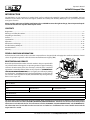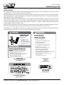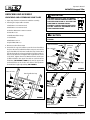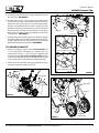
1
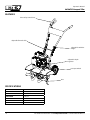
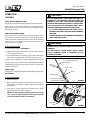
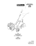
Operator's Manual
Original Operating Instructions
26750TSC
Compact Tiller
GAS/OIL
RATIO
50:1
Product #: 26750TSC
Email for more information
[email protected]
P/N: 13461
ECN: 9580
Rev. 10/11/12
© 2012 Ardisam, Inc.
All Rights Reserved
Operator's Manual
26750TSC Compact Tiller
INTRODUCTION
Congratulations on your investment in quality. Thank you for purchasing the 26750TSC Compact Tiller from HUSKEE®. We have
worked to ensure that this tiller meets the highest standards for usability and durability. With proper care, your tiller will provide
many years of service.
Please read this entire manual before installation and use. HUSKEE reserves the right to change, alter or improve the product and this document at any time without prior notice.
CONTENTS
Registration.........................................................................................................................................................................................................................................2
Warnings and Safety Precautions............................................................................................................................................................................................3-7
Unpacking and Assembly..........................................................................................................................................................................................................8-9
Features..............................................................................................................................................................................................................................................10
Specifications....................................................................................................................................................................................................................................10
Operation.................................................................................................................................................................................................................................... 11-13
Maintenance and Storage..................................................................................................................................................................................................... 13-15
Troubleshooting and Repair........................................................................................................................................................................................................16
Parts Breakdown....................................................................................................................................................................................................................... 17-22
Warranty.............................................................................................................................................................................................................................................23
Federal Emission Information
Ardisam warrants to the retail purchaser, that this compact tiller was designed, built and equipped to conform at the time of initial
sale to all applicable regulations of the U.S. Environmental Protection Agency (EPA).
REGISTRATION AND SERVICE
Record the product model number and serial number in the space provided for
easy reference when ordering parts or requesting technical support. Excluding
emissions-related warranty items, the warranty is valid only if the completed
registration is received by Ardisam within 30 days of purchase. (SEE WARRANTY
SECTION FOR MORE INFORMATION) You can register your warranty by mailing
it to: Ardisam Inc, 1160 Eighth Avenue, Cumberland, WI 54829. You may also call
our customer service department at (800) 345-6007 Mondays through Fridays
from 8 a.m. to 5 p.m. CST.
model and serial
number location
OWNERSHIP RECORDS
Owner’s Name:
Owner’s Address:
City:
State/Province:
Model Number:
Date of Purchase:
Notes:
Serial Number:
Zip Code/Postal Code:
This manual may contain information for several models. Read and keep this manual for future reference. This manual contains
important information on SAFETY, ASSEMBLY, OPERATION, AND MAINTENANCE. The owner must be certain that all the product
information is included with the unit. This information includes the MANUAL, the REPLACEMENT PARTS and the WARRANTIES.
This information must be included to make sure state laws and other laws are followed. This manual should remain with the
engine even if it is resold.
2
For additional information email [email protected] or call 800-345-6007 M-F 8-5
Operator's Manual
26750TSC Compact Tiller
Warnings and Safety Precautions
Operator's RESPONSIBILITY
Accurate assembly and safe and effective use of the machine is
the operator's responsibility.
Danger
Warning INDICATES A HAZARD WHICH, IF NOT
AVOIDED, will RESULT IN DEATH OR SERIOUS INJURY
AND/OR PROPERTY DAMAGE.
• Read and follow all safety instructions.
• Carefully follow all assembly instructions.
• Maintain the machine according to directions and schedule
included in this HUSKEE operator’s manual.
• Ensure that anyone who uses the machine is familiar with all
controls and safety precautions.
SPECIAL Safety MESSAGES
Your manual contains special messages to bring attention to
potential safety concerns, machine damage as well as helpful
operating and servicing information. Please read all the information carefully to avoid injury and machine damage.
NOTE: General information is given throughout the manual
that may help the operator in the operation or service of the
machine.
This symbol points out important safety instructions which if not followed could endanger your
personal safety. Read and follow all instructions
in this manual before attempting to operate this
equipment.
Before Operating Engine:
Please read this section carefully. Read entire operating and
maintenance instructions AND the instructions in the engine
manual that accompanies this product (if applicable). Failure
to follow instructions could result in serious injury or death.
Operate the machine according to the safety instructions
outlined here and inserted throughout the text. Anyone who
uses this machine must read the instructions and be familiar
with the controls.
Warning
Warning INDICATES A HAZARD WHICH, IF NOT
AVOIDED, COULD RESULT IN DEATH OR SERIOUS INJURY AND/OR PROPERTY DAMAGE.
Caution
CAUTION INDICATES YOU CAN BE HURT OR YOUR
EQUIPMENT DAMAGED IF THE SAFETY INSTRUCTIONS THAT FOLLOW THIS SIGNAL WORD ARE NOT
OBEYED.
Important
INDICATES HELPFUL INFORMATION FOR PROPER ASSEMBLY, OPERATION, OR MAINTENANCE OF YOUR
equipment.
Warning
CALIFORNIA PROPOSITION 65 WARNING
Engine exhaust from this product contains
chemicals known to the State of California
to cause cancer, birth defects, or other reproductive harm.
Danger
Warning
You must read, understand and comply with
all safety and operating instructions in
this manual before attempting to setup and
operate your machine.
Failure to comply with all safety and
operating instructions can result in loss of
machine control, serious personal injury to
you and/or bystanders, and risk of equipment
and property damage. The triangle in the text
signifies important cautions or warnings
which must be followed.
SRT
CRT
Intended Use / Foreseeable Misuse
IMPORTANT: This is a motorized rotary tiller that works the
soil by means of rotating tines. It is pedestrian-controlled, but
not self-propelled, with a gasoline-fueled internal combustion
engine to power the tines. It shall not be used for any other
purpose.
For additional information email [email protected] or call 800-345-6007 M-F 8-5
3
Operator's Manual
26750TSC Compact Tiller
General Safety Rules
•
Read, understand, and follow all instructions on the machine
and in the manual(s). Be thoroughly familiar with the controls
and the proper use of the machine before starting.
•
Use this equipment for its intended purpose only.
•
Familiarize yourself with all of the safety and operating
decals on this equipment and on any of its attachments or
accessories.
•
Do not put hands or feet near or under rotating parts.
•
Only allow responsible individuals who are familiar with the
instructions to operate the machine. Do not allow children
to operate this machine. Do not allow adults to operate the
machine without proper instruction.
•
Thoroughly inspect the area where the machine is to be
used and remove all foreign objects. Your equipment can
propel small objects at high speed causing personal injury
or property damage. Stay away from breakable objects, such
as house windows, automobile, greenhouses, etc.
•
Never wear sandals, sneakers, or open shoes, and never
operate the machine with bare feet.
•
Do not wear loose clothing or jewelry. They can get caught in
moving parts. Always keep hands, feet, hair and loose clothing
away from any moving parts on engine and machine.
•
Always wear safety goggles or safety glasses with side shields
when operating the machine to protect your eyes from
foreign objects which can be thrown from the unit. Always
wear a protective hearing device.
•
Always wear work gloves and sturdy footwear. Wear
footwear that will improve footing on slippery surfaces.
•
Do not operate the machine without proper guards, covers,
hoods or other safety protective devices in place.
•
See manufacturer’s instructions for proper operation and
installation of accessories. Only use accessories approved
by the manufacturer.
•
Operate only in daylight or good artificial light.
•
Do not operate product when fatigued or under the
influence of alcohol, drugs or other medication which
can cause drowsiness or affect your ability to operate this
machine safely.
•
Never operate machine in wet grass. Always be sure of your
footing; keep a firm hold on the handle and walk; never run.
•
Watch for traffic when operating near, or when
crossing roads.
•
If the equipment should start to vibrate abnormally, stop the
engine (motor), disconnect the spark plug wire and prevent
it from touching the spark plug. Check immediately for cause.
Vibration is generally a warning of trouble. If the noise or
4
important
The right and left sides of your rototiller are determined from the
operating position as you face the
direction of forward travel.
Engine is shipped from factory without oil. You must add engine oil before starting engine.
L
R
vibrations of the machine increase, stop immediately and
perform an inspection.
•
Never leave the machine unattended when the engine is
running. Remove the wire from the spark plug.
•
Regularly inspect the machine. Make sure parts are not bent,
damaged or loose.
•
Temperature of muffler and nearby areas may exceed 150°
F (65° C). Allow muffler and engine areas to cool before
touching. Never pick up or carry the machine while the
engine is running.
•
Prolonged exposure to noise and vibration from gasoline
engine-powered equipment should be avoided. Take
intermittent breaks and/or wear ear protection from engine
noise as well as heavy work gloves to reduce vibration in
the hands.
•
Keep all screws, nuts and bolts tight.
•
Do not transport the machine from one place to another
with the engine running.
•
When moving the packaged machine, always do so with a
partner.
•
Check local regulations for age restrictions on use of this
machine.
Product-Specific Safety Rules
•
Do not till above underground utilities, including water
lines, gas lines, electric cables, or pipes. Do not operate the
tiller in soil with large rocks and foreign objects which can
damage the equipment.
•
After striking a foreign object, stop the engine. Remove
the wire from the spark plug. Inspect the tiller for damage.
If damaged, repair before starting and operating the tiller.
•
The tines of the tiller should not rotate when the engine
is idling. If they do rotate when engine is idling, contact
customer service for instructions.
•
If an object becomes lodged in the tines, turn engine off,
remove the wire from the spark plug and secure, allow to
cool before attempting to remove the foreign object.
•
The tines can be very sharp. Use extreme caution when tilling
or replacing the tines.
For additional information email [email protected] or call 800-345-6007 M-F 8-5
Operator's Manual
26750TSC Compact Tiller
•
Tines rotate when the tiller is engaged; tines rotate when the
drive safety control lever is pulled down. Releasing the drive
safety control lever to the neutral position stops the tines.
•
Do not overload the machine capacity by attempting to till
too deep at too fast of a rate.
•
Be careful when tilling in hard ground. The tines may catch
in the ground and propel the tiller forward. If this occurs,
let go of the handlebars and do not restrain the machine.
•
Take all possible precautions when leaving the machine
unattended. Disengage all control levers, stop the engine,
wait for all moving parts to stop, and make certain guards
and shields are in place.
Warning
Engines give off carbon monoxide, an odorless, colorless, poison gas. Carbon monoxide
may be present even if you do not smell or see
any engine exhaust. Breathing carbon monoxide can cause nausea, fainting or death, in
addition to drowsiness, dizziness and confusion.
If you experience any of these symptoms, seek
fresh air and medical attention immediately.
Engine Safety Precautions
CAUTION
Warning Carbon Monoxide Poisoning
Hot gases are a normal by-product of a functioning catalytic converter. Follow all safety instructions to prevent burns and fires.
Engines give off carbon monoxide, an odorless, colorless,
poison gas. Carbon monoxide may be present even if you
do not smell or see any engine exhaust. Breathing carbon
monoxide can cause nausea, fainting or death, in addition
to drowsiness, dizziness and confusion. If you experience
any of these symptoms, seek fresh air and medical attention
immediately.
Do Not Alter/Modify engine:
Never alter or modify the engine from the
factory. Serious injury or death may occur if
engine is modified or altered.
When working on or replacing parts for the
engine or product, you must always disconnect spark plug wire from the spark plug and
keep it away from the spark plug.
If your product comes with a separate engine manual, be
sure to read and follow all safety and warning precautions
outlined there, in addition to any in this manual.
Preventing Carbon Monoxide Poisoning
• Always start and run engine outdoors. Do not start or run
engine in an enclosed area, even if doors or windows are
open.
• Never try to ventilate engine exhaust indoors. Carbon
monoxide can reach dangerous levels very quickly.
Gasoline Fires and Handling Fuel Safely
Use extra care in handling gasoline and other fuels. They are
flammable and vapors are explosive.
•
• Never run engine outdoors where exhaust fumes may be
pulled into a building.
When storing extra fuel be sure that it is in an appropriate
container and away from any fire hazards.
•
• Never run engine outdoors in a poorly ventilated area where
the exhaust fumes may be trapped and not easily taken
away. (Examples include: in a large hole or areas where hills
surround your working area.)
Prevent fire and explosion caused by static electric discharge.
Use only nonmetal, portable fuel containers approved by the
Underwriter’s Laboratory (U.L.) or the American Society for
Testing & Materials (ASTM).
•
• Never point the exhaust muffler towards anyone. People
should always be many feet away from the operation of the
engine and its attachments.
Always fill fuel tank outside in a well ventilated area. Never
fill your fuel tank with fuel indoors. (Examples include:
basement, garage, barn, shed, house, porch, etc.) Never
fill tank near appliances with pilot lights, heaters, or other
ignition sources. If the fuel has to be drained, this should be
done outdoors with the proper equipment. The drained fuel
should be stored in a container specifically designed for fuel
storage or it should be disposed of carefully.
•
Never remove the fuel cap or add fuel with the engine
running. Stop engine and allow to cool before filling.
•
•
Never drain fuel from engine in an enclosed area.
• Never run engine in an enclosed or partially enclosed area.
(Examples include: buildings that are enclosed on one or
more sides, under tents, car ports or basements.)
• Always run the engine with the exhaust and muffler pointed
in the direction away from the operator.
Do not change the engine governor settings or over-speed
the engine.
For additional information email [email protected] or call 800-345-6007 M-F 8-5
5
Operator's Manual
26750TSC Compact Tiller
•
Always wipe up excess (spilled) fuel from engine before
starting. Clean up spilled fuel immediately. If fuel is spilled,
do not start the engine but move product and fuel container
from area. Clean up spilled fuel and allow to evaporate and
dry after wiping and before starting.
•
Allow fuel fumes/vapors to escape from the area before
starting engine.
•
Test the fuel cap for proper installation before starting and
using engine.
•
Always run the engine with fuel cap properly installed on
the engine.
•
Never smoke while refilling engine fuel tank or while
operating machine.
•
Do not store engine with fuel in fuel tank indoors. Fuel and
fuel vapors are highly explosive.
•
Never pour fuel from engine fuel tank.
•
Never siphon fuel by mouth to drain fuel tank.
•
Always have an adult fill the fuel tank and never allow
children to fill the engine.
•
Never allow an adult or anyone under the influence of drugs
or alcohol to fill engine.
•
When storing gasoline or equipment with fuel in the tank,
store away from furnaces, stoves, water heaters or other
appliances that have a pilot light or other ignition source
because they can ignite gasoline vapors.
Burns and Fires
The muffler, muffler guard and other parts of the engine become extremely hot during the operation of the engine. These
parts remain extremely hot after the engine has stopped.
Prevention of Burns and Fires
• Never remove the muffler guard from the engine.
• Never touch the muffler guard because it is extremely hot
and will cause severe burns.
• Never touch parts of the engine that become hot after
operation.
• Always keep materials and debris away from muffler guard
and other hot parts of the engine to avoid fires.
• This engine is designed to operate using a catalytic converter
which contributes to the engine’s compliance with the EPA.
Children and bystanders
Tragic accidents can occur if the operator is not alert to the
presence of children and/or bystanders. Never assume that
others will remain where you last saw them.
• Keep the area of operation clear of all persons, especially
small children and pets. Keep children under the watchful
care of a responsible adult.
• Be alert and turn machine off if children enter the area.
• Before and while moving backwards, look behind and down
for small children.
•
Never allow children to operate the machine.
• Use extra care when approaching blind corners, shrubs, trees,
or other objects that may obscure vision.
SERVICE
• Always stop the engine whenever you leave the equipment,
before cleaning, repairing or inspecting the unit. Engine should
be turned off and cool, spark plug wire must be removed from
spark plug before any repairs or adjustments are attempted.
Never make adjustments or repairs with the engine (motor)
running. Disconnect the spark plug wire, and keep the wire
away from the plug to prevent accidental starting. Remove
the ignition key if equipped with an electric start.
• Always wear eye protection when you make adjustments or
repairs.
• Keep all nuts and bolts tight and keep equipment in good
condition.
• Never tamper with safety devices. Check their proper
operation regularly.
• When servicing or repairing the machine, do not tip the machine
over or up unless specifically instructed to do so in this manual.
Service and repair procedures can be done with the machine
in an upright position. Some procedures will be easier if the
machine is lifted on a raised platform or working surface.
• To reduce fire hazard, keep machine free of grass, leaves,
or other debris build-up. Clean up oil or fuel spillage. Allow
machine to cool before storing.
• Stop and inspect the equipment if you strike an object.
Repair, if necessary, before restarting.
•
Clean and replace safety and instruction decals as necessary.
• To guard against engine over-heating, always have engine
debris filter mounted and clean.
• Inspect machine before storage. When not in use, disconnect
spark plug lead and store indoors in a dry place locked or
otherwise inaccessible to children.
• Use only original equipment parts, including all nuts and
bolts.
6
For additional information email [email protected] or call 800-345-6007 M-F 8-5
Operator's Manual
26750TSC Compact Tiller
SAFETY DECALS
This rototiller unit has been designed and manufactured to provide you with the safety and reliability you would expect from
an industry leader in outdoor power equipment manufacturing.
Although reading this manual and the safety instructions it contains will provide you with the necessary basic knowledge to
operated this equipment safely and effectively, we have placed several safety labels on the tiller to remind you of this important
information while you are operating the unit.
These important safety labels are illustrated below, and are shown here to help familiarize you with the location and content
Company: tilling
Ardisamoperations.
Inc.
of the safety messages you will see as you perform normal
Please review these labels now. If you have any
Part No:
18092
questions regarding their meaning or how to comply with these instructions, reread the complete safety instruction text on the
Description: preceding pages, or contact customer service.
Type:
Decal
REV:
Should any of the safety labels become unreadable because
of1being worn, faded, or otherwise damaged during the use of your
Born:
100611
tiller, please use the part number information provided
to order
a replacement label from customer service.
ECN No:
9087
Artist:
Scott Andrew
Waldal
The safety labels are easily applied, and will act as a constant
visual
reminder
to you, and others who may use the equipment.
Follow the safety instructions necessary for safe, effective operation of your rototiller.
DANGER
WARNING
AVOID INJURY FROM
ROTATING TINES!
AVOID SERIOUS
INJURY OR DEATH
Keep hands, feet and
clothing away.
• Tines rotate when tiller
is engaged.
• Tines rotate when drive
control lever is pulled back.
• Releasing the drive control
lever to neutral stops
the tines.
• Read operator’s manual(s).
• Know the location and function of all controls.
• Keep all shields and guards in place
and working while running.
• Never operate tiller when children are around.
OPERATION
• Dress appropriately -- wear sturdy footwear.
• Carefully inspect area to be tilled -remove large rocks and other foreign objects.
REFER TO OPERATOR’S MANUAL FOR
DETAILED OPERATING INSTRUCTIONS
TO START:
1. Release drive control lever to neutral position.
2. Turn ON/OFF switch to ON position.
3. Move throttle control lever to fast position on engine.
4. Move choke lever to choke position on engine.
5. Pull starter rope until engine starts.
6. Move choke lever back to run position.
Part No. 18088
TINES DANGER/OPERATION
Tine Shield Decal
• Do NOT till above underground electric,
water, gas, or other utility lines and pipes.
• STOP THE ENGINE AND DISCONNECT THE SPARK PLUG WIRE
before removing debris or servicing unit.
• When leaving the operating position for any reason:
-- shut off the engine.
-- wait for all moving parts to stop.
18088
Part No. 18091
WARNING
Tine Shield Decal
Colors Used:
Pantone
Process Black
Pantone
179 Orange
IMPORTANT: Please slit backing material to ensure ease of removal.
Part No. LBL3100D
CLUTCH ENGAGE
Handlebar Decal
Part No. LBL516C
BELT AND PULLEY WARNING
Belt Guard Decal
For additional information email [email protected] or call 800-345-6007 M-F 8-5
7
Operator's Manual
26750TSC Compact Tiller
Unpacking and Assembly
Unpacking and Assembling Your Tiller
1. Open top of carton and remove handlebar assembly.
2. Parts bag for compact tiller contains:
2- Bolts M8 x 1.25 x 20 Hex Head
6- Bolts M8 x 1.25 x 25 Hex Head 6- Washers M8 8.4mm x 24mm x 2.2mm
6- Nuts M8 x 1.25
important
The right and left sides of your rototiller are determined from the
operating position as you face the
direction of forward travel.
Engine is shipped from factory without oil. You must add engine oil before starting engine.
L
R
Caution
2- Middle Handlebar Straps
DO NOT TRY TO LIFT THE ROTOTILLER FROM THE
CARTON.
2- Hand Knobs
6- Bolts M6 x 1.0 x 12
6- Nylock Nuts M6 x 1.0
3. Remove machine from carton
upper handlebar
4. Assemble the upper handlebar onto the lower handlebar
loop. Use the two (2) middle handlebar straps to connect the
upper handlebar to the lower handlebar loop. Put the M8 x
25 bolts through the six lower bolt holes from the outside in.
Put on six (6) washers and tighten with six (6) M8 nuts on the
six (6) bolts. Tighten the two (2) M8 hand knobs on the two
(2) M8 x 20 bolts in the upper most hole on each side of the
handlebar. (SEE FIGURES 1 AND 2) The two (2) upper bolts
and hand knobs can be used in one of three hole positions
for handlebar height adjustability. SEE FIGURE 3
M8 x 20 bolts
M8 hand
knobs
M8 x 25 bolts
lower
handlebar loop
handlebar strap
FIGURE 2
M8 x 25 bolts
lower handlebar loop
washers
Lowest Position
M8 nuts
Middle Position
FIGURE 1
Highest Position
8
FIGURE 3
For additional information email [email protected] or call 800-345-6007 M-F 8-5
Operator's Manual
26750TSC Compact Tiller
5. Assemble tine shield extensions using six (6) M6 bolts and six
(6) nylock nuts. SEE FIGURE 4
6. Assemble tines to unit. Sharp edges of tines will be away
from the operator at the top or facedown at front of machine.
Fasten outer tines to the inner tines using the 8mm x 40mm
lock pins already affixed to the inner tines. Lock pins must be
installed so that the pin enters the hole in the tine from the
front of the tiller, and so the wire bale hinges over the top of
the tine pipe and latches to the protruding pin on the back
side of the tine. SEE FIGURE 5
lock pin
7. Install the drag stake assembly from the top down through the
drag stake holder tube on the tiller frame between the wheels.
Lock the drag stake in place using the lock pin that is already
affixed to the drag stake holder tube. SEE FIGURE 6
Fill engine CRANKCASE
1. Add oil according to engine manual. Do not overfill. Use
a clean, high quality detergent oil. Container must be
marked A.P.I. Service SF - SJ. Use no special additives with
recommended oils. Do not mix oil with gasoline. Oil level
must be full. Check the oil level by removing oil fill plug. Oil
level should be up to the bottom of the fill plug opening.
lock pin attached correctly
2. Always check oil level before starting engine. Refer to engine
manual for capacity and type of oil to use.
lock pin attached incorrectly
M6 bolts
FIGURE 5
tine shield
drag stake
lock pin
FIGURE 4
FIGURE 6
For additional information email [email protected] or call 800-345-6007 M-F 8-5
drag stake
holder tube
9
Operator's Manual
26750TSC Compact Tiller
Features
drive safety control lever
adjustable forward cable
adjustable handlebar
height
adjustable depth
regulator
transport wheels
tines
Specifications
ENGINE DISPLACEMENT
99cc
tilling width
11 in., 16 in., 21 in.
tilling DEPTH
11 in.
tine speed
178 rpm
WHEEL SIZE
8” diameter
WEIGHT OF UNIT
90 lb
UNIT SIZE L x W x H (inches)
51” x 24” x 41”
10
For additional information email [email protected] or call 800-345-6007 M-F 8-5
Operator's Manual
26750TSC Compact Tiller
Operation
Controls
Drive SAFETY Control Lever
Engage tines into forward, releasing returns machine to neutral.
Pulling down on drive safety control lever engages the tines.
Releasing the drive safety control lever to a neutral position
disengages the tines.
BELT TENSION ADJUSTMENT
Caution
This information is provided here only to
introduce the controls. DO NOT START THE
ENGINE AT THIS TIME. Starting and operating
instructions are given on page 11. Please read
this section and all operating and safety
instructions before starting your tiller.
• As a safety precaution, the drive safety
control lever will not lock in the forward
position.
Proper belt tension is critical to good performance. After 1/2 hour
of operation, all cables may have to be adjusted due to initial
stretch. Thereafter, check tension after every 2 hours of operation.
Proper tension is achieved when the spring compresses 1/4”
when drive lever is engaged.
• To stop the tines at any time release the drive
safety control lever.
To increase belt tension:
ENGINE SHOULD BE OFF BEFORE ADJUSTING ANY
CONTROLS.
1. Loosen upper jam nut. SEE FIGURE 7
2. Tighten the lower jam nut in 1/8” increments, making sure not
to over adjust the tension.
3.Check adjustment by measuring spring compression when
drive lever is engaged. (Proper spring compression 1/4”)
Warning
Do not adjust tilling depth unless drive
safety control lever is released to the
neutral position.
4. When proper adjustment is achieved, tighten upper jam nut.
drive safety control lever
disengaged
This procedure can be repeated until conduit adjustment bolts
are fully adjusted. If no more adjustment can be made, belt may
need to be replaced.
tension nut
Drag Stake
Tilling depth is controlled by the height of the depth regulator lever.
See Figure 8
To adjust tilling depth.
1.Remove lock pin.
2.Raise the depth regulator lever to position tines at chosen
tilling depth. Lowering the depth regulator will allow for
deeper tilling.
spring
upper jam nut
lower jam nut
forward cable
FIGURE 7
3.Align hole in depth regulator lever with hole in depth
regulator bracket and replace lock pin.
NOTE: Raise depth regulator all the way when transporting
tiller. Lower the depth regulator all the way to maintain
control of the tiller in harder soil conditions.
drag stake
lever
For additional information email [email protected] or call 800-345-6007 M-F 8-5
FIGURE 8
11
Operator's Manual
26750TSC Compact Tiller
PRE-START Inspection
1. Make sure all safety guards are in place and all nuts and bolts
are secure.
2. Check oil level in engine crankcase. See your engine manual
for procedure and specifications.
3. Inspect air cleaner for cleanliness. See your engine manual
for procedure.
4. Check the fuel supply. Fill the fuel tank no closer than 1
inch from top of tank to provide space for expansion. See
your engine manual for fuel recommendations.
5. Be sure spark plug wire is attached and spark plug is tightened securely.
6. Check depth regulator lever position.
7. Examine underneath and around engine for signs of oil or
fuel leaks.
Important
Gasoline is highly flammable and must be
handled with care. Never fill the tank when
the engine is hot or running. Always move
outdoors to fill the tank.
Temperature of muffler and near by areas may
exceed 150° F. Avoid these areas.
Do not move choke control to CHOKE to stop
engine. Backfire or engine damage may occur.
TO STOP THE ENGINE AT ANY TIME, turn the ON/OFF
switch TO THE OFF POSITION. To stop tines at any
time, release drive safety control lever to the
neutral position.
Always release drive safety control lever to
the neutral position and turn engine off before
adjusting the depth of the regulator lever.
8. Inspect fuel hoses for tightness and fuel seepage.
9. Look for signs of engine damage.
10.Remove excessive debris from muffler area and recoil starter.
START-UP
The controls required to start and run the rototiller are located
on the engine.
The throttle speed control is located above the pull-start recoil
and is indicated by a rabbit for FAST and a turtle for SLOW. The
choke lever is located above the air cleaner cover. The On/Off
switch is located on the side of the blower housing closest to
the recoil pull handle.
A more detailed description of engine operation and all related
precautions and procedures can be found in the engine
manufacturer’s manual that accompanies each tiller.
Cold Starts
1. Turn the On/Off switch to the ON position
2. Move choke lever to full choke position.
3. Move throttle lever to half way between the SLOW position
and the FAST position.
Caution
Please do not start your tiller until you
have read the Manual that came with your
engine, and the sections in this manual titled
Controls and Safety. If you have read these,
follow the steps in the start-up section to
start your tiller. Always perform this prestart checklist before starting the engine.
Important
Engine is shipped from factory without oil. YOU
MUST ADD ENGINE OIL BEFORE STARTING ENGINE.
Practice operating the controls and tiller
with tines out of ground before beginning to
till. It is important that you know how to use
the tiller properly, keep control at all times,
stop the tines and wheels from turning, and
stop the engine if necessary. If you do not know
how to do these things, read the Controls and
Safety sections before proceeding.
4. Pull starting rope out slowly one time and allow to return
normally.
Restarting A Warm Engine
5. Pull starting rope out rapidly, and allow rope to return
normally. Repeat until engine starts.
Restarting an engine that is already warm from previous running
does not normally require use of the choke.
6. When engine starts, gradually move choke lever to run
position and increase throttle speed to the FAST position for
tilling.
1. Turn the On/Off switch to the ON position.
2. Move throttle lever to half way between SLOW and FAST.
3. Pull starting rope out rapidly until engine starts. Allow rope
to return normally. Repeat until engine starts.
4. Adjust throttle speed to the FAST position for tilling.
12
For additional information email [email protected] or call 800-345-6007 M-F 8-5
Operator's Manual
26750TSC Compact Tiller
Operating Speed
For normal tilling, set the throttle lever to FAST.
SHUTTING DOWN
To stop the engine at any time, turn the On/Off switch to the
OFF position. To stop tines at any time, release the drive safety
control lever to the neutral position.
Tilling
1. Adjust the depth regulator lever to desired tilling depth.
NOTE: Raise depth regulator lever up one hole at a time, testing
tiller operation after each raise. Raising depth regulator lever too
high can result in loss of control of tiller!
2.Move the throttle control to FAST.
3.Place the tiller in motion by pushing down on the drive safety control
lever--this will engage the tines.
MAINTENANCE AND STORAGE
Your rototiller has been designed and produced by the industry’s
leading manufacturer of outdoor power equipment to provide
you with years of reliable operation.
Please read the maintenance schedule in this manual for the tiller,
and the maintenance schedule and recommendations in the
accompanying engine manual. Observe these recommendations
to extend the life of your product.
Good maintenance is essential for safe, economical, and troublefree operation. Keeping your tiller in top running condition will
prolong its life, and help you obtain optimum performance. It will
also help reduce air pollution. To help you properly care for your
engine, the following pages include a maintenance schedule,
routine inspection procedures, and simple maintenance
procedures using basic hand tools. Other service tasks that
are more difficult, or require special tools, are best handled by
professionals and are normally performed by a technician or
other qualified mechanic.
Maintenance, replacement or repair of the emissions control
devices and systems may be performed by any non-road
engine repair establishment or individuals. However, items
must be serviced by an authorized dealer to obtain “no
charge” emissions control warranty service.
The maintenance schedule applies to normal operating
conditions. If you operate your tiller under unusual conditions,
such as sustained high-load or high-temperature operation, or
use in unusually wet or dusty conditions, consult your servicing
dealer for recommendations applicable to your individual needs
and use.
Danger
E ngine a nd surrounding pa rts beco m e
extremely hot during normal use and will
cause serious burn injuries if touched before
the engine has cooled.
Allow engine to cool completely before
touching these hot surfaces.
Always keep hands and feet clear of rotating
machine parts.
Warning
Extreme caution must be taken in selecting
tilling depth. If you attempt to till with the
drag stake in too high of a position for certain
soil conditions, loss of control could result.
If removing material from the tines by hand,
stop engine and remove spark plug wire first.
MAINTENANCE SCHEDULE
Maintenance
Operation
Page
Before
Each Use
50 hours or
Every Season
Check belt tension
11
X
Change drive belt
14
Engine maintenance
15
x
x
Check or fill engine
crankcase
15
x
1
Clean tine axle shaft
15
x
Lubrication
15
x
x
EM = See engine manual
1 Change oil after first 5-8 hours of use, then after every 50 hours or
every season. Change oil every 25 hours when operating under heavy
load or in high temperatures.
For additional information email [email protected] or call 800-345-6007 M-F 8-5
13
Operator's Manual
26750TSC Compact Tiller
SERVICING THE ROTOTILLER
The following information will help you make the necessary
checks and perform the procedures required to follow the normal
care recommendations made for your rototiller unit.
If you prefer, your local authorized dealer can make these checks
and perform the required procedures for you.
Warning
C heck forwa rd be lt tension regu l a r ly.
Too much or too little tension will cause
premature belt failure.
Warning
Check Belt Tension
Belt tension may decrease over time. It must be adjusted within
the first half hour of operation, and checked after every two hours
of operation. Proper adjustment will assure long belt life. Too
much or too little belt tension will cause premature belt failure.
To check and adjust the forward belt tension:
1. Turn off engine. Engine must be cool.
2. Remove spark plug wire from spark plug and secure.
3. With drive safety control lever in the neutral position, measure
length of spring when in its relaxed state.
To prevent accidental
starting:
Engine must be turned
off and cool, and spark
plug cap/wire must be
removed and secured
from spark plug before
checking and adjusting
engine or equipment.
4. Pull down on drive safety control lever and measure length of
spring when compressed. Ideal length would be 1/4” shorter.
SEE FIGURE 9
spark plug
spark plug cap/wire
drive safety control lever
disengaged
Change Drive Belt
1.Turn off engine. Engine must be cool.
1/4” stretch
2.Remove spark plug wire from spark plug and secure.
3.Remove top and lower belt guards (18129 and 18123).
see figure 10
upper jam nut
• remove the belt from the engine pulley:
- gently pull the engine recoil rope to rotate the pulley.
- with the pulley turning, force the belt out of the groove.
lower jam nut
forward cable
FIGURE 9
- slide the belt free of the engine pulley.
- pull the belt down and out of the way.
top belt guard
- push the belt down and away from the transmission pulley to remove.
• install new belt:
- place belt in transmission pulley groove.
- gently pull the engine recoil rope to rotate the pulley while forcing the belt into the groove.
4.Replace top and lower belt guards (18129 and 18123).
5.Recheck belt tension and adjust if necessary
belt
6.Attach spark plug wire.
FIGURE 10
14
lower belt guard
For additional information email [email protected] or call 800-345-6007 M-F 8-5
Operator's Manual
26750TSC Compact Tiller
Engine Maintenance
Refer to the engine manual included in your parts packet for
information on engine maintenance. Your engine manual
provides detailed information and a maintenance schedule for
performing the following tasks:
1. Check oil level before each use or after every 8 hours of
operation.
2. Change oil after first 5-8 hours of operation. Change oil while
engine is warm. Refill with new oil of recommended grade.
4. Check spark plug seasonally or every 100 hours of operation.
5. Service air cleaner.
6. Keep engine and parts clean.
7. Check engine and equipment often for loose nuts and bolts,
keep these items tightened.
Check or Fill Engine Crankcase
1. Add oil according to engine manual. Do not overfill. Use
a clean, high quality detergent oil. Container must be
marked A.P.I. Service SF - SJ. Use no special additives with
recommended oils. Do not mix oil with gasoline. Oil level
must be full. Check the oil level by removing oil fill plug. Oil
level should be up to the bottom of the fill plug opening on
most engines.
2. Always check oil level before starting engine. Refer to engine
manual for capacity and type of oil to use.
Clean tine axle shaft
1. Turn off engine. Engine must be cool.
2. Remove spark plug wire and secure from spark plug.
3. Remove all vegetation, string, wire, and other material that
may have accumulated on the axle between the inside set of
tines and the seal on the transmission housing.
Warning
Temperature of muffler and near by areas may
exceed 150° F. Avoid these areas.
Warning
Do not store tiller in an unventilated area
where fuel fumes may reach flame, sparks,
pilot lights or an ignited object. Drain fuel
outdoors away from any ignition sources. Use
only approved fuel containers.
Caution
Do not operate tiller before reading the
engine manual provided in the parts packet.
Important
Engine is shipped from factory without oil. You
must add engine oil before starting engine.
Engine can overheat and become damaged if
debris blocks the cooling system or rotating
screen.
Never run engine without complete air cleaner
installed on engine.
instructions or add fuel stabilizer to prevent fuel from
gumming up during extended storage period.
4. Replace spark plug wire.
3. While engine is still warm, drain the oil from the engine. Refill
with fresh oil of the recommended grade.
Lubrication
4. Clean external surfaces, engine and cooling fan.
Proper lubrication of moving mechanical parts is critical for
proper care and maintenance. Oil the moving parts using a 30
weight oil.
5. Remove spark plug, pour one ounce of SAE 30 oil into spark plug hole.
Storage
Prepare for Storage
Follow the steps below to prepare your tiller for storage. Read
your engine manual for detailed instructions on preparing the
engine for storage.
1. Protect tines and tine shafts from rust:
- Coat the tine shaft lightly with axle grease.
2. Drain fuel system completely following engine manufacturer’s
6. Plug hole and pull starter cord slowly to distribute oil evenly
in cylinder head area.
7. Reinstall spark plug.
8. Transport unit to a suitable storage location. If you have chosen
to use a fuel stabilizer and have not drained the fuel system,
follow all safety instructions storage precautions in this manual
to prevent the possibility of fire from the ignition of gasoline
fumes. Remember, gasoline fumes can travel to distant sources
of ignition and ignite, causing risk of explosion and fire.
9. If there is any possibility of unauthorized use or tampering,
remove the spark plug and store it in a safe place before
storing the rototiller unit. Be sure to plug the spark plug hole
to prevent foreign material from entering.
For additional information email [email protected] or call 800-345-6007 M-F 8-5
15
Operator's Manual
26750TSC Compact Tiller
Troubleshooting and Repair
Warning
Troubleshooting Guide
Practice safety at all times. Engine must be
turned off and allowed to cool, and spark
plug wire must be disconnected and secured
before attempting any maintenance or repair.
Failure to comply with this safety requirement
can result in serious personal injury to you
or bystanders.
While normal care and routine maintenance will extend the life
of your rototiller, prolonged or constant use may eventually
require that service be performed to allow it to continue operating properly. The troubleshooting guide below lists the most
common problems, causes and remedies.
Problem
Remedy/Action
Engine will not start
•
•
•
Add gas to gas tank.
Connect spark plug wire to spark plug
Throttle must be positioned at choke for a cold start
Engine runs rough, floods during operation
•
Clean or replace air cleaner
Engine is hard to start
•
Drain old fuel and replace with fresh. Use gas stabilizer at end of
season
Make sure spark plug wire is securely attached to spark plug
Drive safety control lever must be released to neutral to start the
engine
•
•
Engine misses or lacks power
•
•
•
•
•
Raise the tines for shallower tilling by raising the depth regulator lever
Clean or replace air cleaner
Improper carburetor adjustment, take to authorized
engine service center
Replace spark plug and adjust gap
Drain and refill gas tank and carburetor
Tiller moves forward during starting
•
Drive safety control lever must be released to neutral
to start the engine
Tiller is difficult to control when tilling
(machine jumps or lurches forward)
•
•
Lower engine speed in hard ground
Lower the depth regulator for greater control of the tiller
Belts squeal in forward operation
• Adjust belt tension
• Replace drive belt
Excessive heat build up in transmission/tine area during tilling
• Remove vegetation
• Check transmission lubrication and fill if needed
16
For additional information email [email protected] or call 800-345-6007 M-F 8-5
Operator's Manual
26750TSC Compact Tiller
Parts Breakdown
Handlebar assembly Parts explosion and Parts List
7
8
9
6
21
5
18
10
12
11
13
19
17
16
15
14
22
1
2
3
4
20
REF. NO. PART #
3
2
1
DESCRIPTION
QTY.
1
18135
BOLT M8 X 1.25 X 25 SFH GR8.8 ZN
6
2
3245
WASHER M8 8.4MM X 24MM X 2.2MM ZN
6
3
64132
NUT M8 X 1.25 HSF
6
4
18011
STRAP HANDLE BAR MIDDLE
2
5
3359
WELDMENT, HANDLEBAR FT PRO SERIES
1
6
13833
Handlebar Grip 1 in ID
2
7
53650
LEVER CONTROL
1
8
3248
Nut M5 x 0.8 HFNYLK
1
9
13159
Bolt 60D x 32 Shldr M5 x 7mm hh
1
10
53629
BRACKET CABLE MOUNT
1
11
504
LOCKWASHER-SPRING 5/16"
1
12
12770
Bolt M8 x 1.25 x 40mm hh
1
13
13508
Nut M8 1.0 HSF
1
14
13822
Cable ft pulley 787mm sheath
2
15
4620
Nut M8 x 1.25 HJAM
1
16
53620
SPRING COMPRESSION FORWARD ARM
1
17
IN58
NUT 5M x 0.8 NYLOC
1
18
53612
LINK 295MM LONG
1
19
13601
Knob M8 Three Star
2
20
18010
HANDLEBAR LOWER STRAP
1
21
3308
Washer Flat M5 5.3 x 10 x 1.0
1
22
13906
Bolt M8 x 1.25 x 20 SFH
2
For additional information email [email protected] or call 800-345-6007 M-F 8-5
17
Operator's Manual
26750TSC Compact Tiller
2 29 23
11
22 21 7
30
10
9
26
27
6 5
10
15
4
8
10
26
27
25
1
28
11
3
13 14 12
16
18
19
20
17
24
Engine assembly Parts explosion
18
For additional information email [email protected] or call 800-345-6007 M-F 8-5
Operator's Manual
26750TSC Compact Tiller
Engine assembly Parts List
REF.
NO.
PART #
DESCRIPTION
QTY.
1
53617
ARM FORWARD REAR TINE
1
2
13364
Forward Idler Pulley 10mm
1
3
332033
Bolt M10 x 1.5 x 50 hhcs
1
4
W1265V0915 Bolt M8 x 25 hhcs
2
5
W1265V0904 Bolt M8 x 1.25 x 20 HHCS
2
6
18008
BUSHING 16.4MM X 22MM X 21.5MM
1
7
38397
KEY 3/16IN X 1.75IN
1
8
3235
Nut M10 x 1.5 htplk
1
9
803
WASHER 5/16"ID X 1-1/2"OD FLAT
16 GA.
1
10
504
LOCKWASHER-SPRING 5/16"
4
11
WF516
WASHER PLAIN 5/16 ZN
2
12
53596B
YOKE ZINC PLATED CLEVIS
1
13
1416
PIN CLEVIS
1
14
1418
PIN-COTTER
1
15
18015
WELDMENT CABLE GUIDE PLATE
1
16
1407
SPRING FORWARD ARM
1
17
18043
SHIM .25 IN ENGINE MOUNT
2
18
3245
WASHER M8 8.4MM X 24MM X 2.2MM
4
19
W1200114
WASHER M8 X 1.9 SPRLK BLK OX
HIGH COLLAR
4
20
18134
BOLT M8 X 1.0 X 35 GR8.8 ZN
4
21
18036
BELT V POWER RATED 861 MM
1
22
18022
PULLEY SINGLE GROOVE 16MM ID
1
23
739
BELT GUIDE REVERSE
1
24
13276
Engine VIPER 99cc EPA III
1
25
18129
WELDMENT GUARD PULLEY TOP
1
26
4647
BOLT M6 X 1.0 X 18 FLANGE HH GR5
ZN F-T
3
27
W1200116
WASHER M6 X 1.5 SPRLK ZN HIGH
COLLAR
3
28
53637
BUSHING - FORWARD ARM REAR TINE
1
29
W1200126
Washer M10 x 28 x 2.8 Zn
1
30
18104
Bolt M6 x 1.0 x 35 HH
1
For additional information email [email protected] or call 800-345-6007 M-F 8-5
19
Operator's Manual
26750TSC Compact Tiller
23 17
3
15
12
19
11
20
8
20
21
16
11
8
8
13
11
1
4
6
7
10
7
13
2
9
14
5
22
8
18
21
Chassis assembly Parts explosion
For additional information email [email protected] or call 800-345-6007 M-F 8-5
Operator's Manual
26750TSC Compact Tiller
Chassis assembly Parts List
REF.
NO.
PART #
DESCRIPTION
QTY.
1
18004
WELDMENT FRAME
1
2
13366
Lock pin wire bale
1
3
92776
BOLT M6 X 1.0 X 20 HHCS GR8.8 ZN
2
4
18010
HANDLEBAR LOWER STRAP
1
5
W1265V0904
BOLT M8 X 1.25 X 20 HHCS ZN GR8.8
2
6
3245
WASHER M8 8.4MM X 24MM X
2.2MM ZN
2
7
3252
NUT M8 X 1.25 H GR8.8 ZN
4
8
W1265V0913
NUT M6 X 1.0 HNYLK GR8.8 ZN
10
9
3247
BOLT M8 X 1.25 X 45 HHFCS GR8.8 ZN
2
10
400024
WASHER FLAT M8 8.4 X 16 X 1.6
THK GR8.8 ZN
2
11
W1200117
WASHER M6 X 13 X 1.75 FLAT ZN
6
12
18123
WELDMENT GUARD PULLEY
LOWER
1
13
18103
BOLT M6 X 1.0 X 40 HH GR 8.8 ZN
4
14
331052
NUT M12 X 1.75 HH NYLCK GR8.8 ZN
2
15
W1200116
WASHER M6 X 1.5 SPRLCK ZN
2
16
18119
WELDMENT SHIELD TINE MIDDLE
1
17
10513
BOLT M12 X 1.5 X 96 HH SHLDR
M15.7 X 42
2
18
18118
WELDMENT SHIELD TINE RIGHT
1
19
18131
ASSEMBLY DRAG STAKE
1
20
18116
WELDMENT SHIELD TINE LEFT
1
21
18058
BOLT M6 x 1.0 x 12 SBHCS GR8.8 ZN
6
22
10517
WASHER 16MM ID X 25MM OD X
2.5 THK ZN
2
23
13163
WHEEL 8ID x 5/8id in Rubber
2
For additional information email [email protected] or call 800-345-6007 M-F 8-5
21
Operator's Manual
26750TSC Compact Tiller
Transmission assembly Parts Explosion and Parts LIst
20
22
24
28
13
11
10
18
3
19
2
15
17
1
5
26 9 8 27
27
7
12
26
24
6
14
16
21
4
15 14 6
25 23
22
23
25
REF.
NO.
PART #
DESCRIPTION
QTY.
1
13610
Worm Driveshaft 20mm od
REF.
NO.
PART #
DESCRIPTION
QTY.
1
16
13615
Gear Brass 25mm id 6mm Key ft
1
17
13590
Bushing 26mm x 20.22mm x
6.6mm
1
2
8924
RING RETAINING EXTERNAL 3/4 INCH
1
3
13837
Key 5mm x 5mm x 16mm
1
4
13612
Tine Shaft 25mm od 8mm key ft
1
18
13619
Pulley Trans Single Grove
1
5
13611
Key 6mm x 24mm Halfmoon
1
19
3309
Bearing 6004 2rs
1
6
1810
SNAP RING 1" PHOSPH EXTERNAL
2
20
13905
1
7
13613*
CASTING ALUMINUM FT RIGHT SIDE
1
Tine Set outside right FT 25mm
Shaft
8
13614*
CASTING ALUMINUM FT LEFT SIDE
1
21
13904
1
9
13599
Nut M6 x 1.0 HHFNYLK
9
Tine Set outside left ft 25mm
Shaft
10
803
WASHER 5/16"ID X 1-1/2"OD FLAT 16 GA.
1
22
13903
Tine Set inside left or right
25mm shaft
2
11
1916965
WASHER 1/4" SPRING LOCK ZINC
1
23
18098
BOLT M8 x 1.25 x 45 HH GR8.8 ZN
2
12
13600
Bolt M6 x 1.0 x 25 HHF
9
24
3252
NUT M8 X 1.25 H GR8.8 ZN
2
13
W1265V0904
Bolt M8 x 1.25 x 20 HHCS ZN
1
25
18039
13902
Bearing Ball 25mm Id
2
LOCK PIN 8MM X 40MM (38.1MM
USABLE) BLACK
2
14
15
3220
Bearing Tapered Rolling 30204
20 x 47 x 15.2
2
26
W1265V0913
NUT M6 X 1.0 HNYLK GR8.8 ZN
4
27
18137
BOLT M6 x 1.0 x 50 H SHCS GR 8.8 ZN
4
28
13586
Assembly Complete Trans
-
* Right and left castings sold as complete transmission 13586 Assembly only.
22
For additional information email [email protected] or call 800-345-6007 M-F 8-5
Operator's Manual
26750TSC Compact Tiller
Front Tine RotoTillers
Warranty Terms and Conditions
Product Warranty: 1-Year Limited Warranty
Ardisam, Inc., a manufacturing company, warrants this HUSKEE® 26750tsc Compact TILLER to be free from
defects in the material or workmanship for a period of one year from the date of purchase. During the one-year
warranty of this product, Ardisam will furnish, at their discretion, parts and labor to correct any defect caused by
faulty material or workmanship. Any unit used in a commercial application is covered for a period of 90 days after
purchase. This warranty applies to the original owner with a proof of purchase and is not transferable. For the
warranty to be valid, the product must be registered online, or the warranty card must be filled out and received
by Ardisam, Inc., within 30 days of purchase.
*These warranties apply only to products which have not been subjected to negligent use, misuse, alteration, accident, unauthorized parts, failure to use proper fuel and oil, or if repairs have been performed at non-authorized
service centers. These warranties supersede all other warranties either expressed or implied and all other obligations
or liabilities on our part. Ardisam, does not assume, and does not authorize any other person to assume for us, any
liability in connection with the sale of our products. To be at “No Charge,” warranty work must be sent directly
to Ardisam, Inc. or one of our authorized service centers and performed by them. To obtain warranty service
and/or replacement instructions, contact our customer service department. If you choose to ship your product
to Ardisam for warranty repair, you must first have prior approval from Ardisam by calling our customer service
department for a return material authorization number (RMA#). Under these circumstances, all items must be
shipped prepaid. Ardisam will at no charge, repair or replace, at their discretion, any defective part which falls under
the conditions stated above. Ardisam retains the right to change models, specifications and price without notice.
NOTE: For detailed information on this product’s Engine Warranty, refer to the warranty section in the Viper
Engine Manual that accompanies this Operator’s Manual.
1160 Eighth Avenue; P.O. Box 666
Cumberland, Wisconsin 54829
800-345-6007 · Fax (715) 822-4180
E-mail: [email protected]
For additional information email [email protected] or call 800-345-6007 M-F 8-5
23
1160 8th Avenue, PO Box 666
Cumberland, WI 54829
800-345-6007 | Fax 715-822-2223
E-mail: [email protected]
All weights, specifications and features are approximate and are subject to change without notice. Due to continuous product
improvements, product images may not be exact. Items used for props not included. Some assembly may be required.
For additional information email [email protected] or call 800-345-6007 M-F 8-5
Distributed by:
Tractor Supply Co.®
200 Powell Place
Brentwood, TN 37027
www.TractorSupply.com