1
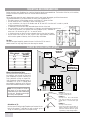
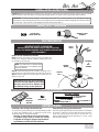
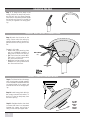
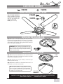
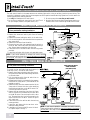
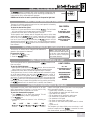
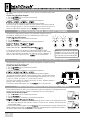
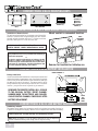
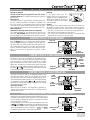
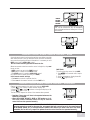
BEL AIR™
OWNER’S MANUAL
CONTENTS
INTRODUCTION . . . . . . . . . . . . . . . . . . . . . . . . . . . . . . . . . . . . . . . . . . . . . . . . . . . . . . . . . . . . . . . . . . . . . . 3
MOUNTING RECOMMENDATIONS . . . . . . . . . . . . . . . . . . . . . . . . . . . . . . . . . . . . . . . . . . . . . . . . . . . . . . . . . . 4
FAN INSTALLATION . . . . . . . . . . . . . . . . . . . . . . . . . . . . . . . . . . . . . . . . . . . . . . . . . . . . . . . . . . . . . . . . . . . 5
INTELI•TOUCH OPERATION . . . . . . . . . . . . . . . . . . . . . . . . . . . . . . . . . . . . . . . . . . . . . . . . . . . . . . . . . . . . . 10
TROUBLESHOOTING: INTELI•TOUCH . . . . . . . . . . . . . . . . . . . . . . . . . . . . . . . . . . . . . . . . . . . . . . . . . . . . . . . 13
COMFORT•TOUCH OPERATION . . . . . . . . . . . . . . . . . . . . . . . . . . . . . . . . . . . . . . . . . . . . . . . . . . . . . . . . . . . 14
TROUBLESHOOTING: COMFORT•TOUCH . . . . . . . . . . . . . . . . . . . . . . . . . . . . . . . . . . . . . . . . . . . . . . . . . . . . . 18
READ AND SAVE THESE INSTRUCTIONS
SAFETY FIRST
Safety and the proper operation of your Casablanca fan both require a thorough knowledge of the
product and proper installation; therefore, before attempting to install and operate your Casablanca
fan, read this owner’s manual completely and carefully. Retain this manual for future reference.
CAUTION: To avoid possible electrical shock, make certain that electricity is turned off
at the circuit breaker or fuse box before attempting any installation procedure.
BEFORE YOU START
• All wiring must be in accordance with the National Electric Code ANSI/NFPA 70-1993 and the appropriate local electrical
codes. The National Electric Code requires proper grounding as a precaution against electrical shock. A qualified electrician should be consulted if you are unsure.
• This fan is designed to be installed on an existing electrical outlet box. The outlet box must be UL Listed for ceiling fan
installations, if it is not, a new box must be installed. Casablanca extension poles are available for sloped or high ceiling
installations.
• This ceiling fan requires a grounded electrical supply of 120 VAC, 60 Hz and a minimum 15 amp circuit. The maximum
current requirement for the fan with light fixture is 3.8 amps. The fan uses about 1 amp or 100 watts. Maximum light
current is 2.8 amps or 340 watts of lighting.
• Where wire nuts are employed, be sure all bare wires are within the connectors. When installing the canopy hatch, make
sure all wires are within the canopy and that no wires are being pinched.
For best performance and for your warranty to be valid,
use only genuine Casablanca blades, light fixtures, and accessories.
SAFE USE
• The blades in each pack are matched for equal
weight to assure smooth fan operation. If
more than one fan is being installed, be
careful not to mix blades from different
cartons.
• Inspect the contents of your carton for
possible shipping or handling damage and
report any such damage directly to your
authorized Casablanca dealer.
• It is always a good idea to have an assistant
to help with the installation.
• When cleaning, painting, or working near
your fan, be very careful of the fan and blades.
Always turn the power OFF to the ceiling fan
before servicing it, working on it, or replacing
light bulbs.
• Never insert anything into the path of the
fan blades while the fan is in operation.
• Never install a fan over a pool or spa.
• Never operate a fan that has been damaged
in any way. Contact Casablanca Fan Company
by calling toll free 888-227-2178, or contact
your local authorized Casablanca dealer for
assistance in obtaining service.
FUSE BOX
(REMOVE FUSE FOR THE
CIRCUIT YOU WILL BE
WORKING ON)
18"
70"
84"
CIRCUIT BREAKER
(TRIP BREAKER FOR THE
CIRCUIT YOU WILL BE
WORKING ON)
P/N 1943660 REV. C
CAUTION: MOUNT WITH THE LOWEST MOVING
PARTS AT LEAST 2.5 METRES ABOVE FLOOR OR
GRADE LEVEL.
ATTENTION: INSTALLER DE SORTE QUELES
PIÈCES INFÉRIEURES SOIENT À AU MOINS 2.5
MÈTRES AU-DESSUS DU PLANCHER OU DU SOL.
P/D DEC96PDG
3
MOUNTING RECOMMENDATIONS
Before mounting your Casablanca fan, read the following helpful recommendations. The location of the fan, air circulation,
and fan size are all important factors to consider before installation.
Location
Ceiling fans have practical uses in almost every room in your home. We suggest you follow these mounting recommendations as you decide where to install your Casablanca fan.
• For safety reasons, the fan blades must be a minimum of 7' above the floor.
• Do not locate the fan in a doorway or above a swinging door.
• In any installation, the tips of the blades must be at least 18" from the wall in order to provide
sufficient clearance for the blades.
• In bedrooms, fans work best when mounted above the foot of the bed.
• Over pool tables, be sure to provide plenty of clearance to avoid damage from pool cues.
• In low ceiling locations, our optional low ceiling adaptor (LCA)—available at
extra cost—can be used to gain 31/2" on som fan series.
• In kitchens be sure to allow for open cupboard doors to clear the fan blades.
• Do not install a fan close to, or over, a pool or spa. High humidity combined
with corrosive gases will destroy the finish and warp the blades.
Fan Size
Variable fan speed capability permits the use of a full-size 52" fan even in
smaller rooms. For very large rooms, two fans may be needed.
SLOPED CEILING INSTALLATIONS
Suggested Extension Pole Lengths
Ceiling Height
Pole Length
8'
Standard
8' 6"
Standard
9'
6"
9' 6"
12"
10'
12"
11'
18"
12'
24"
13'
36"
14'
48"
EXTENSION
POLE
MAXIMUM
HANG-TRU®
ANGLE 32º
BLADES MUST BE A
MINIMUM OF 7'
ABOVE THE FLOOR
7' MINIMUM
When to Use Extension Poles
For best performance and best appearance,
an extension pole should be used with
your Casablanca fan when installing on
high (cathedral) ceilings or sloped ceilings. Casablanca offers standard poles in
increments of 6" up to 5'. Custom poles
are available in lengths up to 10'. See your
Authorized Casablanca Dealer for details.
Note: Fan may wobble or vibrate if
pole length is not long enough and
inside blade is too close to downslope
or side wall. Extending pole length
will usually solve problem.
EXAMPLE 1
This slope is less than 32 .
It is OK to install your fan.
EXAMPLE 2
This slope is 32 .
This is the maximum slope that
will allow the fan to hang straight
down. It is OK to install your fan.
Calculation of 32
Use the tear-off Ceiling Angle Template card inserted in the
back of this manual, it provides you with a simple ‘go’ or
‘no-go’ for installing your fan on a sloped ceiling.
4
32°
EXAMPLE 3
This slope is more than 32 .
Your fan will not hang straight down,
an adaptor is necessary.
Contact you local Authorized
Casablanca Dealer in regards to
purchasing a 'Slope Ceiling Adaptor'.
EXAMPLE 1
This slope is less than 32˚.
It is OK to install your fan.
EXAMPLE 2
This slope is 32˚. This is the maximum
slope that will allow the fan to hang
straight down. It is OK to install your
fan.
EXAMPLE 3
This slope is more than 32˚.
Your fan will not hang straight down, an
adaptor is necessary. Contact your local
Authorized Casablanca Dealer in regards
to purchasing a “Slope Ceiling Adaptor.”
BEL AIR™
INSTALLATION INSTRUCTIONS
Unpacking: Before assembling and installing your ceiling fan, remove all parts from the shipping cartons and check them
against the parts listed here. Before discarding packaging material, be certain that all parts have been removed.
IMPORTANT! To avoid possible damage to the Halogen bulb holder the fan must be placed on the styrofoam packaging
from the box. After removing the top cover from the upper half of the styrofoam, take the packaging from the box and put
it on the floor. Place the fan in the recessed circle that the top cover was in.
PERMA•LOCK™ HARDWARE
LOCKING BOLT
(MOTOR COUPLING)
DOWNROD & BALL
ASSEMBLY
FAN PREPARATION
IMPORTANT SAFETY INFORMATION!
MOTOR
WIRES
BEFORE STARTING THE INSTALLATION OF YOUR CEILING FAN,
INSTALL THE THREADED DOWNROD INTO THE MOTOR COUPLING AND
LOCK THE ASSEMBLY
GROUND
WIRE
Prepare for fan installation as follows:
Step A. Route the wires from the motor through the
Perma•Lock™ downrod and ball assembly, keeping the wires
to one side of the cross pin.
NOTE: The downrod has a tapered thread
that is designed to lock completely when
correctly installed.
TAPERED
THREAD
Step B. Thread the downrod into the motor coupling until it
stops turning, this will take at least four and a half full turns.
Step C. Securely tighten the locking bolt to ensure safe operation of your fan.
DOWNROD
&
BALL
ASSEMBLY
LOCKING
BOLT
MOTOR
COUPLING
CAUTION: Failure to fully lock in the downrod before securely tightening the locking
bolt may cause the fan to separate from
the downrod during normal operation!
CEILING HARDWARE
ADDITIONAL HARDWARE
CROSSBAR
MOUNTING
BRACKET
WIRE NUT (4)
21/4" x 8-32 ROUNDED
HEAD SCREW (2)
1" x 8-32 ROUNDED
FLAT WASHER (2)
HEAD SCREW (2)
GETTING STARTED
Installing a New Ceiling Fixture Outlet Box
If you do not have an existing fixture located where you wish
to place your Casablanca fan, an approved ceiling fixture
outlet box must be installed and wired.
Warning: To reduce the risk of fire, electrical shock,
or personal injury, mount to outlet box marked
acceptable for ceiling fan support using the mounting hardware provided with the outlet box.
Using Existing Ceiling Fixture Outlet Box
After turning the power OFF at its source (either circuit breaker
or fuse box), lower the old fixture and disconnect the wiring.
Check the ceiling fixture outlet box to be sure that it is
marked ‘Approved for ceiling fan mounting’. If it is not, a new
box must be installed.
5
BEL AIR™
CROSSBAR MOUNTING BRACKET INSTALLATION
Proceed with installation as follows:
Step 1. Route the wires from the ceiling outlet box through
the crossbar mounting bracket center hole. Attach the bracket,
with ground wire and ridges down, to the ceiling fixture outlet box with the mounting hardware included with the outlet
box.
Tighten the screws firmly by hand only, being careful not to
bend the bracket by over tightening.
CAUTION: To reduce the risk of
personal injury, use only the
mounting hardware provided with
the approved outlet box to install
the crossbar mounting bracket.
CEILING FAN
APPROVED
OUTLET BOX
RIDGE
SIDE
DOWN
CEILING
WIRING
CROSSBAR
MOUNTING
BRACKET
FLAT
WASHER
OUTLET BOX
MOUNTING
HARDWARE
GREEN
GROUND
WIRE
CANOPY/GLASS HARDWARE
CANOPY SCREW (4)
CANOPY LOCK WASHER (4)
CANOPY
HATCH
CANOPY
GLASS SHADE
HALOGEN BULB
100 WATT
BODY TOP COVER
CANOPY INSTALLATION
Step 2. Attach the canopy to the crossbar mounting bracket with three of the 8-32 x 2 1/4" long
canopy screws and canopy lock washers.
Tighten the screw firmly by hand only.
Note: On sloped ceilings, align the
canopy opening towards the top or
room peak.
CROSSBAR MOUNTING
BRACKET INSTALLED
CANOPY
CANOPY LOCK
WASHERS
CANOPY
SCREWS
6
BEL AIR™
INSTALLING THE FAN BODY TOP COVER
IMPORTANT! To avoid possible damage to the
Halogen bulb holder the fan must be placed on
the styrofoam packaging from the box. After
removing the top cover from the upper half of
the styrofoam, take the packaging from the box
and put it on the floor. Place the fan in the
recessed circle that the top cover was in.
TOP COVER
RETAINING
SCREWS
Step 3. Locate the three
tabs on the top of the fan
motor assembly.
Remove the three top
cover retaining screws and
set aside for Step 6.
NOTE: Make a note of the
Fan Serial Number and
Model Type before installing the top cover.
FAN
MOTOR
ASSEMBLY
Step 4. Locate the top
cover and note the three
mounting tabs on the top.
Step 5. Lower the top
cover over the fan downrod
with the top cover mounting tabs lined up with the
tabs on the fan motor assembly.
Step 6. Once the tabs are
aligned, attach the top
cover to the motor using
the three top cover retaining screws removed in
Step 3. Hand tighten ensuring that all screws are
engaged.
TOP COVER
MOUNTING
TABS
TOP
COVER
TOP COVER
RETAINING
SCREWS
Test that the cover is on
securely before continuing
with the installation.
7
HANGING THE FAN
Step 7. To hang the fan body in the
canopy, hold the fan body firmly and insert the ball into the canopy opening.
Check that no wires were pinched. Rotate
the fan body until the slot in the ball fits
into the pin opposite the canopy opening.
CANOPY ELECTRICAL CONNECTIONS
Step 8. Attach the fan wires to the
ceiling fixture outlet box wiring by
twisting the bare ends of the wires together and then securing with a wire
nut.
Connect in this order:
• GREEN leads from mounting plate
and fan to GROUND conductor of
power source. Secure with wire nut.
• WHITE wire from fan to white NEUTRAL wire in ceiling fixture outlet
box. Secure with wire nut.
• BLACK wire from fan to black (or red)
POWER wire in ceiling fixture outlet
box. Secure with wire nut.
WHITE WIRES
(2)
GREEN WIRES
(3)
WIRE NUT
CANOPY HATCH INSTALLATION
Step 9. Tuck the wires into the canopy
with the wire nuts pointed upwards,
so that the WHITE and BLACK wires are
on opposite sides of the canopy and
all wires are clear of the canopy opening.
Step 10. Install canopy hatch with the
last canopy screw and lock washer. To
do this, tilt the fan body away from
the hatch opening.
Step 11. Straighten the fan, then check
to ensure that there is no movement
between the canopy and ceiling or
Hang-Tru ball and top support shaft.
8
TILT THE
FAN TO
INSTALL
LAST
CANOPY
SCREW
BEL AIR™
BLADE HOLDER HARDWARE
BLADE SCREW
(4 PER BLADE)
FLAT WASHER
(4 PER BLADE)
CENTER STYLE BLADE HOLDER & BLADE
Step 12. Blade Installation
Attach the blades to the blade
holders with four blade screws
and four steel washers provided for each blade.
Hand tighten securely.
BLADE SCREW
(4 PER BLADE)
FLAT WASHER
(4 PER BLADE)
INSTALLING THE HALOGEN BULB
Step 13. Screw the 100 Watt Halogen bulb into the socket.
Do not touch the glass bulb with your fingers–it is extremely
important that the glass be clean. If it is touched, or dirty,
clean carefully with a tissue. A dirty glass bulb will cause the
bulb to fail almost immediately.
IMPORTANT! When installing the halogen bulb, carefully cut off the end of the plastic sleeve the bulb
comes in and hold the bulb by the plastic sleeve to
screw it into the socket.
HALOGEN BULB
100 WATT
INSTALLING THE GLASS SHADE
Step 14. Position the indentations in the outer rim of the
glass shade so that they line up with the tabs on the inside
surface of the fan light fixture rim.
TABS
LIGHT
FIXTURE
Step 15. Carefully lift the glass shade up inside the light
fixture as far as it will go.
Step 14. Rotate the shade in a clockwise direction until it is
held tightly in place by the three tabs.
TIP: At first the shade is a very loose fit in the
fixture and can be ‘wiggled’ a little from side to
side. It is a great help when rotating the glass shade
to ‘wiggle’ it at the same time.
GLASS SHADE
INDENTATION
GLASS
SHADE
PROCEED TO YOUR FAN’S CONTROL FEATURE SECTION FOR INSTALLATION/OPERATING INSTRUCTIONS:
INTELI•TOUCH = PAGE 10
COMFORT•TOUCH = PAGE 14
9
R
INTELI•TOUCH© INSTALLING THE W-32 WALL CONTROL
The wall control installs in the same manner as an ordinary light switch, using an existing junction box and wiring. This
controller is designed to signal the fan microcomputer as well as perform normal switching operations. For this reason the
following precautions must be observed:
1. Use only the Casablanca W-32 wall control.
3. Do not use more than one fan per wall control.
2. Do not use any additional control with your Inteli-Touch 4. No other light fixtures or electrical appliances may be confan (for example, dimmer, fan speed control, etc.).
nected on the circuit controlled by the W-32 wall control.
INTELI•TOUCH ♦ SINGLE W-32 INSTALLATION
CAUTION! Ensure power is turned OFF at the breaker
or fuse panel before starting installation.
W-32 is used to describe either white (-11) or ivory finish.
1. Remove the screws and switch plate from the existing
switch box.
2. Remove the screws holding the switch in the switch box.
3. Pull the existing switch from the switch box to expose the
wire connections.
4. Remove the two wires from the switch.
5. Connect the two wires just removed from the switch to
the W-32 wall control black wire and black/white stripe
wire. Secure these connections with wire nuts.
6. Install the W-32 in the wall box with the two long screws
provided.
7. Install the wall plate with the two color matched screws.
NOTE: If wall control operation is reversed (fan switch controls
lights and light switch controls fan) turn off the power at the breaker
or fuse panel, then swap the two W-32 black/white stripe wires.
INTELI•TOUCH ♦ DUAL W-32 INSTALLATION
CAUTION! Ensure power is turned OFF at the breaker
or fuse panel before starting installation.
To control the fan and lights from two locations (a
three-way circuit), use 2 W-32 wall controls.
1. Remove the screws and switch plate from the existing switch box and the screws holding the switch
in the switch box.
2. Pull the existing switch from the switch box to
expose the wire connections.
3. Determine which wire is connected to the common
terminal of the 3-way switch. (The terminal will be
marked on switch).
4. Remove the wire from the common terminal of the
3-way switch. Connect this wire to the remaining
black/white striped wire on the W-32 control. Secure this splice with a wire nut.
5. Remove the two remaining wires from the 3-way
switch. Connect one of these wires to a black wire
on the W-32 control. Secure the splice with a wire
nut. The remaining wire is to be connected to the
other black wire on the W-32. Secure the splice
with a wire nut.
6. Install the W-32 in the wall box with the two long
screws provided.
7. Install the wall plate with the two short colormatched screws provided.
8. Installation of the second W-32 control is identical. Repeat steps 1 through 7.
10
SWAP THESE TWO WIRES
WHEN NECESSARY
(SEE NOTE BELOW)
R
R
END
OF
LINE
IN
LINE
NOTE: If wall control operation is reversed (fan switch controls
lights and light switch controls fan) turn off the power at the breaker
or fuse panel, then swap the two W-32 black/white stripe wires.
R
INTELI•TOUCH OPERATION ♦ POWER
The
button is normally left in the on position. Always turn the
power off during cleaning or servicing the fan and during thunderstorms. It
is also used to exit or enter additional programs.
POWER must be left on to retain a previously set fan speed or light level.
INTELI•TOUCH OPERATION ♦ SPEED CONTROL
There are six individual speed settings for the fan; each speed is indicated by
an audible tone of increasing pitch.
To select the desired fan speed:
1. With fan off, press and hold the button labeled
. The fan blades
will start rotating at the slowest speed, and will increase in steps.
2. Release the button when the desired speed is reached.
The fan speed is now in memory and will automatically come on at the same
speed each time the
button is used. To maintain this level of speed,
turn the fan on by pressing
less than one second. To lower speed,
turn fan off, then on by pressing and holding the
button until the
desired speed is reached. When the fan is on, you may increase the speed by
button until the desired speed is reached,
pressing and holding the
then release it.
FAN CONTROL
ON - OFF:
R
A momentary press
of the FAN button
CHANGE SPEED:
Press and hold FAN
button longer than
one second
INTELI•TOUCH OPERATION ♦ REVERSING AIRFLOW
The direction of airflow can be changed from downward to
upward or from upward to downward.
To reverse the airflow:
1. Make sure the
is on.
2. Press the
button.
Note: A four-toned signal indicates the command was accepted
by the fan. A few seconds later
the fan will slow to a stop and
then reverse direction.
INTELI•TOUCH OPERATION ♦ LIGHT
button for less
To turn the lights off and on, press and release the
than one second.
To vary the light brightness:
1. With lights off, press and hold the
button. After one second the
lights come on at their lowest level and gradually become brighter.
2. Release the button when the desired brightness level is reached.
The brightness level is now in the fan memory and will automatically come
on at the same brightness the next time the
button is used. To
maintain this level of brightness, press the
button for less than
one second. To lower the brightness, turn the lights off, then press and hold
the
button until the desired brightness level is reached. When the
light is on, you may increase the brightness level by pressing and holding
the
button until the desired level is reached, then release it.
LIGHT CONTROL
ON - OFF:
R
A momentary press of
the LIGHT button
CHANGE BRIGHTNESS:
PRESS AND HOLD
LIGHT BUTTON
LONGER THAN ONE
SECOND
AUTOMATIC DEMONSTRATION PROGRAM
Programmed into every Inteli-Touch Series fan is an Automatic Demonstration Program. It can be used to fully
demonstrate and test the operation of the fan.
To enter the demonstration program:
1. Turn
off for at least three seconds. This will
clear the fan memory ready for programming.
2. Turn
on.
3. Immediately operate the buttons in the following sequence:
FAN
- LIGHT
+
-
+
FAN
- LIGHT -
+
+
FAN
A multi-tone signal will verify the start of the test program
which proceeds as follows:
• Lights slowly increase to full intensity.
• Fan accelerates to speed three with audio tones.
• Light dims to half intensity.
• Fan accelerates to full speed with audio tones.
• Fan reverses at full speed with audio tones.
• Fan operates at full speed.
• Fan power is reversed with audio tones.
• Fan turns off with audio tones (blades coast for a short
time).
• Lights turn off.
The complete cycle lasts slightly over one minute. It will
continue to repeat until the
is turned off for more
than three seconds, cancelling the program.
11
R
INTELI•TOUCH OPERATION ♦ LIGHT-MINDER® PROGRAM
The Light-Minder program automatically turns OFF the fan mounted lights after
two hours.
To enter the Light-Minder Program:
1. Turn the
OFF for at least three seconds.
2. Turn the
ON.
3. Immediately operate the buttons in the following sequence:
+
+
+
4. A series of tones indicates this command has been accepted.
The fan and light will operate normally using the buttons to turn them on and off.
But, if the lights are left on, they will automatically shut off after two hours. To
cancel the Light-Minder Program, turn the
off for three seconds.
INTELI•TOUCH OPERATION ♦ SAFE-EXIT® PROGRAM
The Safe-Exit Program gives you about thirty seconds of light when you turn
the lights off, enabling you to exit your home before the lights go out.
To enter the Safe-Exit Program:
1. Turn the
off for at least three seconds.
2. Turn the
on.
3. Immediately operate the buttons in the following sequence:
+
+
+
After you hear the confirming audio
tones from the fan - immediately press
4. The lights will blink to indicate this command has been accepted.
The lights will stay on for twenty seconds and then begin to dim. After a
total of thirty seconds has elapsed, the lights will be off completely. To
cancel the Safe-Exit Program, turn the
off for three seconds.
Note: Both Light-Minder and Safe-Exit
programs can run at the same time,
however the dimmer cannot be used,
the light may only be turned ON/OFF.
INTELI•TOUCH OPERATION ♦ HOME-SAFE® PROGRAM
The Home-Safe Program makes an unoccupied home appear occupied by turning
the lights on and off at random times.
To enter the Home-Safe Program:
1. Turn the
off for at least three seconds.
2. Turn the
on.
3. Immediately operate the buttons in the following sequence:
+
+
+
4. A tone and flashing light indicate this command has been accepted.
This program overrides all manual control of lights and fan. The lights will now be
automatically cycled on and off in a controlled sequence as follows: On 1 hour, off
1
/2 hour, on 2 hours, off 1 hour, on 1/2 hour then off 2 hours.
This seven hour pattern will repeat continuously so that a different pattern of
lighting is seen each day of the week.
To cancel the Home-Safe Program, turn the
off for three seconds.
INTELI•TOUCH OPERATION ♦ FAN-MINDER™ PROGRAM
The Fan-Minder feature will add to your comfort when used in the bedroom. The program reduces the
speed of the fan each two-hour interval to compensate for the cooling night air.
To enter the Fan-Minder Program:
1. Turn the
off for at least three seconds.
2. Turn the
on.
3. Immediately operate the buttons in the following sequence:
+
+
+
4. The fan controller will respond with three descending tones. A timer is now initiated and the fan
will reduce one speed for each two-hour interval. The fan will not, however, descend below the
second lowest speed.
To cancel the Fan-Minder Program, turn the
off for three seconds. You may increase the fan
speed by pressing and holding the
button until the desired speed is reached, then release it.
The fan will again reduce one speed for each 2 hour interval.
12
R
TROUBLESHOOTING
Before Requesting Service: Please follow this troubleshooting guide before contacting your dealer for assistance.
Caring for Finishes: For cleaning, a soft brush or lint-free cloth
should be used to prevent scratching the finish. A vacuum cleaner
brush nozzle can remove heavier dust. Surface smudges or an accumulation of dirt and dust can easily be removed by using a mild
detergent and slightly dampened soft cloth. An antistatic agent
may be used, but never use abrasive cleaning agents. These will
damage the finish. Painted and high-gloss blades may be cleaned
in the same manner.
Blades: Wood finish blades should be cleaned with a furniture polishing cloth. Occasionally, a light coat of furniture polish may be
applied for added protection and beauty.
PROBLEM
Never Lubricate this Fan!
The precision motor at the heart of your Casablanca fan features
sealed bearings that are lubricated for life. Do not attempt to oil
the motor.
Changing Light Bulbs
Be sure to turn power to the fan OFF at the wall switch or circuit
breaker before changing light bulbs. Replace bulbs with same type
as removed from the fixture. Each fan is rated for a maximum TOTAL
wattage of lighting.
Exceeding the rated maximum allowable wattage for the fan will
burn out the fan electronics module and void the warranty.
INTELI•TOUCH
POSSIBLE REMEDIES..
NO FAN OR LIGHT
Check main circuit fuses, curcuit breakers, or wall switch position. Check all wire connections, making
sure the power is turned off during this inspection.
FAN WOBBLES OR SHAKES
EXCESSIVELY
Be sure canopy pin is properly set into the slot on the ball
Check the screws holding the blade holders to the fan motor. Tighten as necessary.
Check the angle of the blades to make sure that a blade holder has not been bent during installation.
FAN NOISY DURING
OPERATION
Check and tighten light fixture retaining screws, glass shade screws and/or the light bulb(s).
Tighten canopy screws and mounting plate assembly.
Tighten the blade to bladeholder screws and blade holders to flywheel.
Make sure all screws in the motor housing are snug, but not overly tight.
Check that the wire nuts inside the canopy and switch housing are not touching the metal parts or
have fallen off the wire splices. Tighten or adjust as necessary.
BREAK-IN PERIOD
Let fan run at high speed for two (2) hours
DOES NOT RUN ON
LOW SPEED
If new, “break-in” may be required - run at higher speed for several days
LIGHTS FLASH OR BLINK DURING OPERATION OF W-32 WALL CONTROLS/FAN MAY ROTATE OR MAKE AUDIBLE TONES DURING
OPERATION OF THE W-11 AND W-12 WALL CONTROLS: Normal operation.
WHEN AC POWER IS TURNED ON FOR THE FIRST TIME, THE LIGHTS OPERATE NORMALLY, BUT W-32 WALL CONTROL OPERATION IS
REVERSED: FAN BUTTON OPERATES THE LIGHTS; LIGHT BUTTON OPERATES THE FAN: Reverse the 2 black and white striped wire
connections.
FAN OR LIGHTS APPEAR TO OPERATE BY THEMSELVES (CHANGING SPEED OR INTENSITY), WALL CONTROL OPERATION IS INTERMITTENT: Check AC supply for irregularities, (noise spikes, fluctuations, or failure); or circuit board assembly.
13
COMFORT•TOUCH ♦ W-21 MOUNTING PARTS
R
WALL BRACKET
ANCHOR (4)
REMOTE CONTROL
W-21
REMOTE CONTROL
WALL BRACKET
‘AAA’ ALKALINE
BATTERY (3)
WALL BRACKET
SCREW (4)
COMFORT•TOUCH ♦ W-21 WALL BRACKET INSTALLATION
Installation of Remote Control
The wall mounting bracket for the remote control should be
located in a position that is approximately eye level. Secure
the wall mounting bracket with the 11/4" screws or anchors
provided, making sure it is level with the floor.
Mount control in convenient location
WALL
MOUNTING
BRACKET
CAUTION! DO NOT MOUNT REMOTE CONTROL ON OR NEAR
A METAL SURFACE - ERRATIC OPERATION WILL OCCUR.
Changes or modifications not expressly approved in writing by Casablanca Fan Co. may void the user’s authority to
operate this equipment.
•••
This device complies with RSS-210 of Industry Canada.
Operation is subject ot the following two conditions: (1)
this device may not cause interference, and (2) this device
must accept any interference, including interference that
may cause undesired operation of the device.
Remove for handheld or tabletop use
COMFORT•TOUCH ♦ W-21 BATTERY INSTALLATION
PRESET CHANNEL #
Battery Installation
Install three ‘AAA’ alkaline batteries in the sequence shown and
replace the battery compartment cover, then press the remote
control firmly to the wall bracket so that the Velcro® pads grip
the pads on the rear of the control. The remote control can be
easily removed at any time should you wish to use it in another
location. Just give the control a gentle tug to remove it.
-
REMEMBER THE REMOTE CONTROL WILL GO BACK
TO THE ORIGINAL FACTORY ‘PRESET CHANNEL’
NUMBER WHEN THE BATTERIES ARE CHANGED.
CHANGE CONTROL CHANNEL IF NECESSARY AFTER
BATTERY REPLACEMENT.
+ -
+
+
-
COMFORT•TOUCH ♦ W-21 LOW BATTERY WARNING
Low Battery Indicator
The remote control warns of a low battery condition by displaying a rapidly flashing ‘Lo’
in place of the temperature display. When this occurs replace with fresh alkaline battery.
WARNING: Use of batteries other than non-leak sealed alkaline in the
remote control will void the warranty and can destroy the unit.
Note: When the remote is in the low battery mode the fan may not respond to
control commands correctly even though the fan may be running.
14
SPACE
FOR
ROOM
LABEL
COMFORT•TOUCH ♦ IMPORTANT OPERATING NOTES
Turning On Your Fan
The fan will not receive any signals for the first 20 seconds after power on. This allows the electronics to warm up
and stabilize.
Power Failure
The remote control is not affected by household power failure as it is battery operated. Once power is restored to the
fan it will receive an auto-update signal from the remote
control within 30 minutes after power is restored. All previously set modes and functions will be restored to the fan.
Button Operation
Rapid button pressing causes erratic fan operation.
For reliable operation of the remote control and fan you
must wait ONE SECOND between button presses to allow
the radio signal to be transmitted to the fan and received.
R
Labeling
If you have more than one
Comfort•Touch fan in your home, we
suggest you put an adhesive room
identification label on the back of
the control. Labels are in the remote
SPACE FOR LABEL
control package.
General
Your Comfort•Touch remote control uses one of 15 different radio signals to control the fan. This channel is set at the factory.
There may be times when the channel needs to be changed,i.e.:
• Two fans in the house set to the same causing interference.
• Two fans are to be operated from one control.
• Two controls are to operate the same fan - see special 'Dual
Remote Control' section on the next page.
COMFORT•TOUCH ♦ TEST PROGRAM
Press the
button to activate a two minute program
that puts the fan through a complete functional test. The
test starts with a full screen display, then the 'preset' channel number before going into a full light, fan and reverse
exercise. Follow the remote control LCD display and compare it to the actual fan operation to confirm correct
operation.
FULL LCD
SCREEN DISPLAY
W-21
TEMPERATURE
TEST
BUTTON
COMFORT•TOUCH ♦ FAN OPERATION
The Comfort•Touch fan is controlled by the remote control.
The fan is turned on and off by alternate pushes of the large
right hand button. As with all button operations, an audio
tone sounds with each push. With the fan on, the control
display will indicate an up or down moving arrow that shows
direction and places a box around the operating speed. The
two small
and
buttons below the fan button increase
or decrease speed once for each press.
FAN
ON/OFF
BUTTON
SPEED
UP/DOWN
BUTTONS
R
AIRFLOW
DIRECTION
FAN SPEED
COMFORT•TOUCH ♦ LIGHT OPERATION
The light is turned on and off by alternate pushes of the
large left hand button. When on, the display will indicate
the light bulb symbol and a vertical segment display representing brightness. When the light is on, the brightness may
be changed by using the small
and
buttons below the
light button. Pressing and holding either button will change
the brightness continuously.
Bulb-Saver Feature
When the light is turned on, the brightness is gradually increased until it reaches the preset level. This feature helps
extend light bulb life.
LIGHT
ON/OFF
BUTTON
LIGHT
UP/DOWN
BUTTONS
BRIGHTNESS
INDICATOR
COMFORT•TOUCH ♦ ADDITIONAL CONTROL FEATURES
Additional control program features are available from the control panel by opening the control panel door. To activate a control
function press the appropriate button; the display will indicate
that the program is running.
In some cases you can run more than one program at once, such
as
and SAVER and the display will indicate that they are
both activated. In other cases one program will override another
as the two programs can not run together i.e. AUTO and WINTER .
Full details are explained in the sections that follow.
CONTROL PANEL
DOOR
CONTROL
PANEL
15
Pressing the REVERSE button will change the direction of rotation. An audio tone signals
the beginning of the reverse sequence and you will see the airflow direction arrow
changing. The fan gradually slows to a stop, then reverses direction.
REVERSE
COMFORT•TOUCH ♦ AUTO-SPEED FEATURE
In the Auto Speed mode, fan speed changes in response to changes in room temperature. Push the AUTO button to start. The words 'AUTO SPEED' show on the display. Set
the fan speed to the speed at which you are most comfortable. Once set, the fan will
increase or decrease by one speed for each 1.5 F increase or decrease in temperature.
If temperature decreases enough to turn the fan OFF, the Auto Speed indicator will
flash slowly to remind you that the fan will turn on when the temperature increases.
Temperature Accuracy
COMFORT•TOUCH ♦ SAVER FEATURE
The Saver mode will automatically turn lights off 1 hour after the
lights are turned on. Press the SAVER button and 'SAVER' will appear in
the display. An audio tone will warn you 20 seconds before the program is going to turn the lights off. Press the SAVER button again to
cancel.
16
REMOTE
CONTROL
CHANNEL
NUMBER
Note: Always change the remote control channel
first. The fan channel can only be changed by
having the desired channel already set in the remote control.
COMFORT•TOUCH ♦ DUAL REMOTE CONTROL - BASE
A second remote control can be purchased from your dealer to provide
dual remote control of one fan. Because the fan could be confused by
two controllers signaling different information it is necessary to set a
BASE control and an AUXILIARY control.
The last control manually operated controls the fan.
Where two remote controls are used to control a single fan, they must
be set so that:
• BOTH controls are set to the SAME channel.
• ONE control is made into the BASE control.
• The OTHER control is made an AUXILIARY control.
(All remote controls leave the factory as a BASE).
Initial remote control settings
1. Set both the controls to operate the fan.
2. Select one of the remote controls to be the BASE unit.
BASE
DISPLAY
BASE Check
To confirm that the control is the BASE:
1. Press
for 3 seconds until a beep is
heard.
2. Confirm temperature display shows 'b'.
3. Press
again to set.
COMFORT•TOUCH ♦ DUAL REMOTE CONTROL - AUXILIARY
Change the other remote to be used in the room to AUXILIARY
1. Press
until a beep is heard. Remote displays 'b'.
2. Press fan up
or down
buttons to change the display to 'A'.
3. Press
again to set.
The fan will now respond to either of the remotes when pressed.
• Reminder! These steps will have to be repeated whenever the
batteries are changed.
• When AUTO-SPEED, SECURITY, SAVER or TEST modes are in effect at any control: Automatic control will only be from the
control that was last operated manually.
AUXILIARY
DISPLAY
TWO CONTROLS OPERATING ONE FAN
When two controls are used for the same fan, we suggest that both controls be set for the same features
(AUTO-SPEED, SAVER, etc.) so that performance remains the same as you move from one to the other.
Remember, the fan will only respond to updates from the control that was last operated manually.
17
R
TROUBLESHOOTING
Before Requesting Service: Please follow this troubleshooting guide before contacting your dealer for assistance.
Caring for Finishes: For cleaning, a soft brush or lint-free cloth
should be used to prevent scratching the finish. A vacuum cleaner
brush nozzle can remove heavier dust. Surface smudges or an accumulation of dirt and dust can easily be removed by using a mild
detergent and slightly dampened soft cloth. An antistatic agent
may be used, but never use abrasive cleaning agents. These will
damage the finish. Painted and high-gloss blades may be cleaned
in the same manner.
Blades: Wood finish blades should be cleaned with a furniture polishing cloth. Occasionally, a light coat of furniture polish may be
applied for added protection and beauty.
PROBLEM
Never Lubricate this Fan!
The precision motor at the heart of your Casablanca fan features
sealed bearings that are lubricated for life. Do not attempt to oil
the motor.
Changing Light Bulbs
Be sure to turn power to the fan OFF at the wall switch or circuit
breaker before changing light bulbs. Replace bulbs with same type
as removed from the fixture. Each fan is rated for a maximum TOTAL
wattage of lighting.
Exceeding the rated maximum allowable wattage for the fan will
burn out the fan electronics module and void the warranty.
COMFORT•TOUCH
POSSIBLE REMEDIES..
FAN O.K., NO LIGHT
Check for burned-out light bulb. Check fan light wires.
REMOTE CONTROL OF FAN IS ERRATIC
Check batteries installed correctly. Install fresh ALKALINE batteries.
SELECTING WINTER MODE CANCELS AUTO-SPEED
Normal.
CHANGING SPEED OR DIRECTION CANCELS WINTER
Normal.
FAN APPEARS TO RESPOND TO UNKNOWN SIGNAL
Change channel of control and fan to a number between 49 and 63.
CONTROL ALSO OPERATES A SECOND FAN IN HOME
Change channel on control and fan.
TEMPERATURE DISPLAY DOES NOT CHANGE QUICKLY
Normal. Updates only every 2 minutes.
FAN WOBBLES OR SHAKES EXCESSIVELY
Make sure hanging ball slot is properly aligned.
Tighten canopy and mounting crossbar screws.
Tighten all blade screws. Blades must be balanced (contact your dealer).
FAN NOISY DURING OPERATION
Tighten glassware and light bulbs.
Tighten motor housing screws.
Tighten canopy and mounting crossbar screws.
DOES NOT RUN ON LOW SPEED
If new, “break-in” may be required - run at higher speed for several days.
BATTERY LIFE SEEMS SHORT
Not using Alkaline batteries: Replace with Alkaline batteries.
TEMPERATURE READINGS
Temperature accuracy =
FAN DOES NOT RESPOND TO REMOTE CONTROL: Power to fan is off; wrong remote being used; remote channel changed; fan receive SET
channel changed; or fan antenna not receiving. See above; in locations with two or more fans in different rooms check that controllers are
in right rooms; change SET channel to match fan; change fan SET channel to match remote; check antenna connected to RCM; check
antenna positioned correctly; if batteries weak by moving remote close to fan; check that remote not laying on metal surface causing
weak signal; or connect Earth ground to fan.
FAN APPEARS TO RESPOND TO UNKNOWN SIGNAL OR IS ERRATIC: Invalid lower channel SET; 2nd remote in area SET to same channel;
or remote buttons pressed too quickly Be sure SET channel is between 49 and 63; check SET channels of any other remotes at site (check
if nearby homes have Comfort Touch fans installed- remote signal can travel 50 ft.); and for proper operation of the control you must wait
“one second” between presses.
AFTER POWER FAILURE, FAN AND LIGHTS ARE OFF: Normal: To immediately restore fan to its original settings press any button. Fan will
reset itself within about 30 minutes after power is restored when remote sends normal update message to fan.
WHEN AC POWER IS TURNED ON, LIGHT COMES ON OR FAN TURNS: Remote control defective; remote buttons pressed too soon; AC
electricity irregularities (noise spikes, fluctuations, or failure). Turn off with remote and restart; replace remote control unit; or wait
twenty seconds for electronics warm-up; check AC electricity for irregularities (defective light dimmers, noise spikes, voltage changes
caused by appliances, motors, supply brown outs or interruptions, or storms, etc).
18
761 CORPORATE CENTER DRIVE • POMONA, CA 91768
TOLL FREE: 888-227-2178
www.CasablancaFanCo.com
©COPYRIGHT 1999 CASABLANCA FAN COMPANY • U.S. PATENT PENDING