1
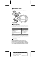
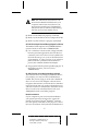
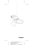
Installation Guide
APA-358 MiniSCSI EPP
Enhanced Parallel-to-SCSI Host Adapter
R
AA
AAAA
AAAA
AAAA
AA
AAAAAAAA
AAAAAAAA
AAAAAAAA
AAAAAAAA
AAAAAAAA
AAAAAAAA
AAAAAAAA
AAAAAAAA
AAAAAAAA
AAAAAAAA
AAAAAAAA
AAAAAA
AAAAA
AA
APA-358 Installation Guide
AA
AA
AA
AA
AA
Part Number: 510604-00, Rev. A
AA
AA
AA
AA
Print
Spec
Number:
492717-00
AA
AA
AA
AA
Current Date: 5/19/94
ECN Date: 5/31/94 AA
AA
AA
AAAAAAAAAAAAAAAAAAAAAAAAAAAAAAAAAAAAAAAAAAAAAAAAAAAAAA
1 Overview
This Installation Guide explains how to physically
install and configure Adaptec APA-358 MiniSCSI™
EPP Enhanced Parallel-to-SCSI host adapters. Your
adapter has been designed to provide simple, flexible control of most SCSI devices. The adapter’s ultra
high-speed operation enables it to be fully compatible with enhanced parallel ports (EPP), offering
excellent performance while remaining compatible
with bidirectional and unidirectional ports found on
many older computer systems. Both SCSI and parallel printer interfaces may be operated simultaneously, with no performance degradation.
Hardware Requirements
The MiniSCSI EPP is designed to be as universally
usable as possible, but there are five primary hardware compatibility requirements:
■
The parallel port must be standard—i.e., have a
fully IBM®-compatible hardware design, including all ground lines. For highest performance, the
computer’s parallel port must be EPP compliant.
■
The SCSI device chain must be properly terminated as per ANSI SCSI specifications.
■
The SCSI device(s) connected to the MiniSCSI
EPP must have the standard ANSI SCSIspecification TERMPOWER implemented, since
the adapter draws its power from this line. See
your dealer for details.
■
■
IBM or compatible AT®, PS/2®, or similar
computer.
A 100% IBM-compatible BIOS. Operation with an
incompatible BIOS may be possible but is not
guaranteed.
Checklist
You should have received the following items in
your MiniSCSI EPP package:
■
APA-358 MiniSCSI EPP host adapter
■
3.5-inch, 1.44-MBytes software diskettes
1
A
AAAA
AAAA
AAAA
A
AAAAAAAA
AAAAAAAA
AAAAAAAA
AAAAAAAA
AAAAAAAA
AAAAAAAA
AAAAAAAA
AAAAAAAA
AAAAAAAA
AAAAAAAA
AAAAAAAA
AAAAAA
AA
A
AA
APA-358 Installation Guide
A
AA
A
AA
A
AA
Part
Number:
510604-00,
Rev.
A
A
AA
A
AA
A
AA
Print
Spec
Number:
492717-00
A
AA
A
AA
A
AA
Current
Date:
5/19/94
ECN
Date:
5/31/94
A
AA
A
AAAAAAAAAAAAAAAAAAAAAAAAAAAAAAAAAAAAAAAAAAAAAAAAAAAAAA
AA
■
APA-358 MiniSCSI EPP Installation Guide
■
Software User Guide
■
Product Registration card
■
Microsoft® MSCDEX Registration card
If anything is missing, please contact your dealer.
2 What is EPP?
This section gives you a brief overview of the
Enhanced Parallel Port (EPP) design and how the
adapter functions to incorporate the increased performance of EPP.
EPP is a major breakthrough in enhancing parallel
port performance. Current parallel ports achieve
data transfer rates of between 50 and 260 KBytes/
sec, but the EPP reaches up to 1 MBytes/sec.
How is this achieved? Current device drivers for
parallel port peripherals require several instructions
to be executed for each byte of data transferred. With
EPP, each byte requires a single I/O instruction, substantially reducing overhead per byte. These features, plus improved hardware design, significantly
improve the performance of parallel-connected
peripherals.
There is no need to specify whether an EPP device is
being connected—faster EPP transmission rates are
automatic. When not running in EPP mode, the port
operates at standard parallel rates, providing compatibility between EPP and non-EPP parallel ports
and peripherals.
With the new MiniSCSI EPP, you can take advantage
of this new EPP technology and achieve the best performance for your peripherals. The adapter provides easy connection of peripherals and is roughly
as fast as a conventional 8-bit ISA-bus SCSI adapter.
The MiniSCSI EPP is also backward compatible
with non-EPP unidirectional and bidirectional parallel ports. Simply connect the adapter to your parallel
port, and it detects which port you have.
2
A
AAAA
AAAA
AAAA
A
AAAAAAAA
AAAAAAAA
AAAAAAAA
AAAAAAAA
AAAAAAAA
AAAAAAAA
AAAAAAAA
AAAAAAAA
AAAAAAAA
AAAAAAAA
AAAAAAAA
AAAAAA
AA
A
AA
APA-358 Installation Guide
A
AA
A
AA
A
AA
Part
Number:
510604-00,
Rev.
A
A
AA
A
AA
A
AA
Print
Spec
Number:
492717-00
A
AA
A
AA
A
AA
Current
Date:
5/19/94
ECN
Date:
5/31/94
A
AA
A
AAAAAAAAAAAAAAAAAAAAAAAAAAAAAAAAAAAAAAAAAAAAAAAAAAAAAA
AA
3 Host Adapter Layout
This diagram shows the APA-358 components.
4 Default Settings
The MiniSCSi EPP operates correctly with its factory
default settings in most PCs. The default settings are
Parameter
Host Adapter SCSI ID
Host Adapter Termination
Port Address
Speed Selection
Extended Translation for Drives Over
1 GByte
1
2
Default Setting
7
Enabled
378h (Options: 278h, 3BCh1)
Fastest possible for EPP2
Automatic (Enabled)
The 3BCh setting can only be used for bidirectional and unidirectional configurations; it is not applicable for EPP.
Use the /M switch to lower the transfer rate as required for certain parallel ports.
See The MiniSCSI EPP Does Not Function on page 7 and the Software User
Guide for more details on the /M options.
5 Installation
Hardware installation involves plugging the
MiniSCSI EPP into a parallel printer port and connecting it to the applicable SCSI device(s). Follow the
steps carefully in each subsection below to correctly
install the MiniSCSI EPP.
3
A
AAAA
AAAA
AAAA
A
AAAAAAAA
AAAAAAAA
AAAAAAAA
AAAAAAAA
AAAAAAAA
AAAAAAAA
AAAAAAAA
AAAAAAAA
AAAAAAAA
AAAAAAAA
AAAAAAAA
AAAAAA
AA
A
AA
APA-358 Installation Guide
A
AA
A
AA
A
AA
Part
Number:
510604-00,
Rev.
A
A
AA
A
AA
A
AA
Print
Spec
Number:
492717-00
A
AA
A
AA
A
AA
Current
Date:
5/19/94
ECN
Date:
5/31/94
A
AA
A
AAAAAAAAAAAAAAAAAAAAAAAAAAAAAAAAAAAAAAAAAAAAAAAAAAAAAA
AA
Connecting the MiniSCSI EPP
WARNING: Turn OFF the computer, printer,
and SCSI devices when connecting or disconnecting the MiniSCSI EPP. This protects
against damage to any components.
Connect the MiniSCSI EPP parallel port connector to
a parallel printer port on your computer. You may
use either LPT1, LPT2 or LPT3—the MiniSCSI EPP
drivers automatically detect which port is in use.
If your parallel printer port has a copy-protection
device (commonly known as a dongle) or other nonprinter product connected to it, you should remove
the device from your printer port and connect it to
the printer passthrough connector on the MiniSCSI
EPP. If this arrangement causes any problems,
either the dongle or the MiniSCSI EPP must be relocated to a different parallel port.
Connecting SCSI Peripherals
1 Connect the first SCSI device to the SCSI connector on the MiniSCSI EPP.
2 Connect other SCSI devices (up to seven total) by
daisy-chaining them to the first SCSI device.
SCSI devices are daisy-chained by connecting
cables in a single, continuous series called the
SCSI bus. SCSI bus cables must run directly from
one device to the next, with no branches. The
SCSI connector on the MiniSCSI EPP is a 50-pin
Centronics-type external connector.
Caution: The MiniSCSI EPP supports only
single-ended SCSI devices. Do not connect
differential SCSI devices to it. Read the
device’s documentation to determine
whether it is single-ended or differential.
4
A
AAAA
AAAA
AAAA
A
AAAAAAAA
AAAAAAAA
AAAAAAAA
AAAAAAAA
AAAAAAAA
AAAAAAAA
AAAAAAAA
AAAAAAAA
AAAAAAAA
AAAAAAAA
AAAAAAAA
AAAAAA
AA
A
AA
APA-358 Installation Guide
A
AA
A
AA
A
AA
Part
Number:
510604-00,
Rev.
A
A
AA
A
AA
A
AA
Print
Spec
Number:
492717-00
A
AA
A
AA
A
AA
Current
Date:
5/19/94
ECN
Date:
5/31/94
A
AA
A
AAAAAAAAAAAAAAAAAAAAAAAAAAAAAAAAAAAAAAAAAAAAAAAAAAAAAA
AA
Assigning SCSI IDs
If you connect more than one SCSI device to your
MiniSCSI EPP simultaneously, make sure that each
device’s SCSI ID (device number between 0 and 6) is
different; ID 7 is reserved for the adapter and cannot
be changed. IDs must be different to prevent conflicts
when the adapter communicates with the devices.
See your SCSI device documentation for details.
Terminating the SCSI Bus
The SCSI devices on both ends of the SCSI bus must
be terminated. See the following subsections for
details on termination.
Terminating the Host Adapter
MiniSCSI EPP termination is set to Enabled by
default. This setting cannot be changed.
Terminating SCSI Peripherals
1 Read the manufacturer’s documentation to determine how to enable or disable termination on
SCSI device(s).
2 Install or enable terminators on the last SCSI
devices at the end of the SCSI bus.
3 Remove terminators or disable termination on all
other peripheral devices in the middle of the SCSI
bus.
4 Be sure the SCSI cables are connected securely.
They may have been loosened if you changed
jumper or switch settings on the peripherals.
Termination Power
The SCSI device(s) connected to the MiniSCSI EPP
provides power to the adapter and, thus, must be
equipped with the standard TERMPOWER output
(which is part of the SCSI connector interface specification). See your SCSI device manual or dealer to
confirm this. Your MiniSCSI EPP requires TERMPOWER to operate.
5
A
AAAA
AAAA
AAAA
A
AAAAAAAA
AAAAAAAA
AAAAAAAA
AAAAAAAA
AAAAAAAA
AAAAAAAA
AAAAAAAA
AAAAAAAA
AAAAAAAA
AAAAAAAA
AAAAAAAA
AAAAAA
AA
A
AA
APA-358 Installation Guide
A
AA
A
AA
A
AA
Part
Number:
510604-00,
Rev.
A
A
AA
A
AA
A
AA
Print
Spec
Number:
492717-00
A
AA
A
AA
A
AA
Current
Date:
5/19/94
ECN
Date:
5/31/94
A
AA
A
AAAAAAAAAAAAAAAAAAAAAAAAAAAAAAAAAAAAAAAAAAAAAAAAAAAAAA
AA
Caution: If you disconnect your SCSI
device(s) from the MiniSCSI EPP while in
use, the adapter loses power and cannot recognize the device(s) when reconnected.
Reboot your computer in this case.
Connecting the Printer
Connect a standard parallel printer cable to the
MiniSCSI EPP printer passthrough connector if you
wish to simultaneously use a parallel printer with
your MiniSCSI EPP. No special configuration or
switching is needed to use your printer.
For U.S. Residents Only: Use the printer cable
included in your kit to connect the MiniSCSI
EPP to your printer. This cable is shielded to
comply with FCC-mandated requirements
for a Class B computing device. Use of any
other printer cable may result in noncompliance with FCC shielding requirements and
undesirable electronic interference with
other devices.
The printer port on the MiniSCSI EPP functions only
while it is powered up; if you disconnect or turn OFF
the connected SCSI device, the printer passthrough
port on the adapter cannot function.
Completing the Installation
1 Turn ON the power for the PC and device(s).
2 Load the software as explained in the Software
User Guide.
In most cases your PC, MiniSCSI EPP, and peripherals are now ready to use.
6 Troubleshooting
If you have a problem during installation, check the
items below. Be sure to read the Troubleshooting section in the Software User Guide for other remedies.
6
A
AAAA
AAAA
AAAA
A
AAAAAAAA
AAAAAAAA
AAAAAAAA
AAAAAAAA
AAAAAAAA
AAAAAAAA
AAAAAAAA
AAAAAAAA
AAAAAAAA
AAAAAAAA
AAAAAAAA
AAAAAA
AA
A
AA
APA-358 Installation Guide
A
AA
A
AA
A
AA
Part
Number:
510604-00,
Rev.
A
A
AA
A
AA
A
AA
Print
Spec
Number:
492717-00
A
AA
A
AA
A
AA
Current
Date:
5/19/94
ECN
Date:
5/31/94
A
AA
A
AAAAAAAAAAAAAAAAAAAAAAAAAAAAAAAAAAAAAAAAAAAAAAAAAAAAAA
AA
Note: You cannot boot from a device connected to the MiniSCSI EPP because your
computer cannot boot from a device connected to the parallel port. The MiniSCSI
EPP device drivers must be loaded during
the boot process from another device.
■
Make sure all cables are properly connected.
■
Make sure all SCSI devices have unique SCSI IDs.
■
Make sure the SCSI bus is properly terminated.
No SCSI Host Adapter Detected Message Appears at Bootup
The MiniSCSI EPP requires SCSI TERMPOWER to
operate. Check for SCSI device TERMPOWER:
■
Use a voltmeter to measure the voltage available
between pin 38 and ground on the SCSI device’s
connector (see SCSI Connector Pinouts). Make sure
the SCSI device(s) power is ON; it should measure
approximately +5 volts. Very low or no voltage at
pin 25 indicates a problem with termination
power; this condition disables the adapter.
■
Plug a printer into the printer passthrough port. If
the printer can print, you have correct
TERMPOWER.
No SCSI Functions in Use Message Appears at Bootup
The software driver is looking for a different device.
For example, you may have the CD-ROM driver
loaded, but you are trying to work with a hard disk
drive or vice versa. Each Adaptec software driver
recognizes the existence of all SCSI devices attached
to the SCSI chain but only works with the device for
which it is written to communicate. Install the correct
driver or remove an unwanted driver from your
config.sys file with a text editor program.
Network Installations
If your computer is part of a network installation,
your printer port may be redirected to a network
printer. For instance, Novell® NetWare® software
uses the capture command for this purpose. If this is
the case, the software will not detect the hardware at
7
A
AAAA
AAAA
AAAA
A
AAAAAAAA
AAAAAAAA
AAAAAAAA
AAAAAAAA
AAAAAAAA
AAAAAAAA
AAAAAAAA
AAAAAAAA
AAAAAAAA
AAAAAAAA
AAAAAAAA
AAAAAA
AA
A
AA
APA-358 Installation Guide
A
AA
A
AA
A
AA
Part
Number:
510604-00,
Rev.
A
A
AA
A
AA
A
AA
Print
Spec
Number:
492717-00
A
AA
A
AA
A
AA
Current
Date:
5/19/94
ECN
Date:
5/31/94
A
AA
A
AAAAAAAAAAAAAAAAAAAAAAAAAAAAAAAAAAAAAAAAAAAAAAAAAAAAAA
AA
bootup. The simplest solution is to change your computer’s parallel port hardware to LPT2 or LPT3, or
change your network redirection to a different port.
The MiniSCSI EPP Does Not Function
1 In the mode configuration switch /Mnm at the end
of the line device=[path]ma358.sys in your
config.sys, set the value of n to 1.
The /Mnm switch must have both n and m values
specified. For example, enter /M70 (n or m must
be set to 0 if not being used). (See Device Driver
Options in the Software User Guide.)
Note: For non-Intel 386SL or 486SL based
computers, modify the value of m first. Set
the switch to /M08 to force EPP mode. Then
follow the tests in a through c. If you discover problems, modify the n value as
explained in steps 1 through 3.
After setting the switch, perform the tests below
to ensure the adapter is functioning properly:
a Perform a dir command on a hard disk drive
and/or a CD-ROM drive. Check if a problem
is evident, such as absurdly wrong numbers or
corrupted file names being reported.
b Try copying a large (greater than 100 KBytes, if
possible) file from the SCSI device to a nonSCSI hard disk or floppy drive. Then use the
DOS comp command to compare the new
copy to the original file. Check if a problem is
evident, such as the file comparison failing.
c Copy a large file from your non-SCSI drive to
a SCSI rewritable device. Again, compare the
two files with the comp command. Check if a
problem is evident, such as the file comparison failing.
2 If your MiniSCSI EPP still does not function properly, repeat step 1 with other n values such as 2, 3,
4, 5, 6, and 7 until the adapter works. The idea is
to optimize performance by selecting the lowest n
8
A
AAAA
AAAA
AAAA
A
AAAAAAAA
AAAAAAAA
AAAAAAAA
AAAAAAAA
AAAAAAAA
AAAAAAAA
AAAAAAAA
AAAAAAAA
AAAAAAAA
AAAAAAAA
AAAAAAAA
AAAAAA
AA
A
AA
APA-358 Installation Guide
A
AA
A
AA
A
AA
Part
Number:
510604-00,
Rev.
A
A
AA
A
AA
A
AA
Print
Spec
Number:
492717-00
A
AA
A
AA
A
AA
Current
Date:
5/19/94
ECN
Date:
5/31/94
A
AA
A
AAAAAAAAAAAAAAAAAAAAAAAAAAAAAAAAAAAAAAAAAAAAAAAAAAAAAA
AA
value that works with your EPP; typically the
value of 2 works with most parallel ports with
this problem.
Caution: If your MiniSCSI EPP still does not
work after trying all these tests, it may not be
compatible with your parallel port. Contact
technical support.
3 If you share the MiniSCSI EPP with other systems, set up each system individually for proper
performance with the MiniSCSI EPP. Be sure to
follow the instructions in steps 1 and 2 to ensure
compatibility.
Older Sharp Laptops
Some older 8086-based Sharp® laptops do not work
properly with the MiniSCSI EPP or with other programs that use high-speed parallel port data transfer,
such as LapLink® or DeskLink® from Traveling
Software. Sharp offers a free hardware upgrade for
customers experiencing this problem; contact your
Sharp dealer for details.
7 SCSI Connector Pinouts
This section documents the SCSI interface connector
on the MiniSCSI EPP as well as typical connectors
found on SCSI devices. Internal SCSI devices commonly use a 50-pin header connector (SCSI specification, Alternative 1), consisting of two rows of 25
male contacts with adjacent contacts 2.54 mm
(0.1 inch) apart, as shown below.
..........................
..........................
Internal SCSI
Connector
A typical single-ended shielded SCSI device 50-pin
connector (SCSI specification, Alternative 2) is
shown below; this connector is most often used with
an external SCSI device.
9
A
AAAA
AAAA
AAAA
A
AAAAAAAA
AAAAAAAA
AAAAAAAA
AAAAAAAA
AAAAAAAA
AAAAAAAA
AAAAAAAA
AAAAAAAA
AAAAAAAA
AAAAAAAA
AAAAAAAA
AAAAAA
AA
A
AA
APA-358 Installation Guide
A
AA
A
AA
A
AA
Part
Number:
510604-00,
Rev.
A
A
AA
A
AA
A
AA
Print
Spec
Number:
492717-00
A
AA
A
AA
A
AA
Current
Date:
5/19/94
ECN
Date:
5/31/94
A
AA
A
AAAAAAAAAAAAAAAAAAAAAAAAAAAAAAAAAAAAAAAAAAAAAAAAAAAAAA
AA
External SCSI
Connector
Table 1 lists the pin assignments for each connector
type. Definitions of the various signals may be found
in any SCSI design reference book. The SCSI interface is fully defined in ANSI X3.131-1986; this document is available from Global Engineering
Documents, 2805 McGaw Ave, Irvine, CA
92713-9539 USA, telephone (714) 261-1455.
Pin
Alt. 1
Internal
1
3
5
7
9
11
13
15
17
19
21
23
25
27
29
31
33
35
37
39
41
43
45
47
49
Pin
Alt. 2
External
1
2
3
4
5
6
7
8
9
10
11
12
13
14
15
16
17
18
19
20
21
22
23
24
25
Function
Gnd
Gnd
Gnd
Gnd
Gnd
Gnd
Gnd
Gnd
Gnd
Gnd
Gnd
Gnd
Open
Gnd
Gnd
Gnd
Gnd
Gnd
Gnd
Gnd
Gnd
Gnd
Gnd
Gnd
Gnd
Function
-DB0
-DB1
-DB2
-DB3
-DB4
-DB5
-DB6
-DB7
-DBP
Gnd
Gnd
Gnd
Termpwr
Gnd
Gnd
-ATN
Gnd
-BSY
-ACK
-RST
-MSG
-SEL
-C/D
-REQ
-I/O
Alt. 1
Internal
2
4
6
8
10
12
14
16
18
20
22
24
26
28
30
32
34
36
38
40
42
44
46
48
50
Alt. 2
External
26
27
28
29
30
31
32
33
34
35
36
37
38
39
40
41
42
43
44
45
46
47
48
49
50
8 Adaptec Customer Support Services
■
For information on software upgrades, new releases, technical
advice, and other topics, call Adaptec’s Electronic Bulletin
Board Service (BBS) 24 hours a day at 408-945-7727;
1200/2400/9600/14400 baud, 8 data bits, 1 stop bit, no parity.
10
A
AAAA
AAAA
AAAA
A
AAAAAAAA
AAAAAAAA
AAAAAAAA
AAAAAAAA
AAAAAAAA
AAAAAAAA
AAAAAAAA
AAAAAAAA
AAAAAAAA
AAAAAAAA
AAAAAAAA
AAAAAA
AA
A
AA
APA-358 Installation Guide
A
AA
A
AA
A
AA
Part
Number:
510604-00,
Rev.
A
A
AA
A
AA
A
AA
Print
Spec
Number:
492717-00
A
AA
A
AA
A
AA
Current
Date:
5/19/94
ECN
Date:
5/31/94
A
AA
A
AAAAAAAAAAAAAAAAAAAAAAAAAAAAAAAAAAAAAAAAAAAAAAAAAAAAAA
AA
■
For the latest online information about Adaptec products and
services, call the Interactive Fax Service 23 hours a day, 7 days a
week, at 408-957-7150.
■
For technical assistance, call Adaptec’s Technical Support Hot
Line at 800-959-SCSI (7274), or 408-945-2550. M–Th: 6:00 a.m.–
5:00 p.m., F: 6:00 a.m.–3:00 p.m., Pacific Time.
■
To order Adaptec software and SCSI cables, call 800-442-SCSI
(7274), M–F: 6:00 a.m. to 5:00 p.m., Pacific Time. If you are calling from outside the U.S. and Canada, the number is
408-957-SCSI (7274).
■
To request literature on Adaptec products, call 800-934-2766.
M–F: 5:00 a.m.–6:00 p.m., Pacific Time.
FCC Compliance Statement
NOTE: This equipment has been tested and found to comply with the limits
for a Class B digital device, pursuant to Part 15 of the FCC rules. These limits are designed to provide reasonable protection against harmful interference in residential installations. This equipment generates, uses, and can
radiate radio frequency energy, and if not installed and used in accordance
with the instructions, may cause harmful interference to radio communications. However, there is no guarantee that interference will not occur in a
particular installation.
If this equipment does cause interference to radio or television equipment
reception, which can be determined by turning the equipment off and on,
the user is encouraged to try to correct the interference by one or more of the
following measures:
•
•
•
Reorient or relocate the receiving antenna
Move the equipment away from the receiver
Plug the equipment into an outlet on a circuit different from that to
which the receiver is powered
• If necessary, the user should consult the dealer or an experienced radio/
television technician for additional suggestions
CAUTION: Only equipment certified to comply with Class B (computer
input/output devices, terminals, printers, etc.) should be attached to this
equipment, and must have shielded interface cables.
Finally, any change or modifications to the equipment by the user not
expressly approved by the grantee or manufacturer could void the user's
authority to operate such equipment.
Each APA-358 is equipped with an FCC compliance label which shows only
the FCC Identification number. The full text of the associated label follows:
This device complies with part 15 of the FCC rules. Operation is
subject to the following two conditions: (1) this device may not
cause harmful interference and (2) this device must accept any interference received, including interference that may cause undesired
operation.
Adaptec, Inc.
691 South Milpitas Blvd.
Milpitas, CA 95035
Copyright © 1993, 1994 Adaptec, Inc. All rights reserved. Adaptec
and the Adaptec logo are registered trademarks of Adaptec, Inc.
MiniSCSI is a trademark of Trantor Systems Limited, an Adaptec
company. All other trademarks used are owned by their respective owners.
Printed in Singapore
Stock No.: 510604-00, Rev. A CV 5/94
Information subject to change without notice.
11
A
AAAA
AAAA
AAAA
A
AAAAAAAA
AAAAAAAA
AAAAAAAA
AAAAAAAA
AAAAAAAA
AAAAAAAA
AAAAAAAA
AAAAAAAA
AAAAAAAA
AAAAAAAA
AAAAAAAA
AAAAAA
AA
A
AA
APA-358 Installation Guide
A
AA
A
AA
A
AA
Part
Number:
510604-00,
Rev.
A
A
AA
A
AA
A
AA
Print
Spec
Number:
492717-00
A
AA
A
AA
A
AA
Current
Date:
5/19/94
ECN
Date:
5/31/94
A
AA
A
AAAAAAAAAAAAAAAAAAAAAAAAAAAAAAAAAAAAAAAAAAAAAAAAAAAAAA
AA