1
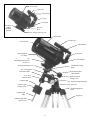
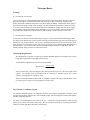
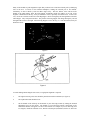
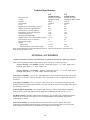
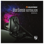
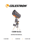
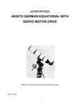
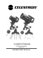
G-3 and G-5 Telescope
Models #11090 / #11091 / #11050/ #11051
CG-3 Equatorial Mount
Model #91503-A
INSTRUCTION MANUAL
Focuser Ring
Finderscope
Finder Bracket
Eyepiece
Star Diagonal
¼"x20 Photo
Adapter
Mounting
Platform
Mounting
Block
Photo Adapter Tightening Knob
Optical Tube
Fig 1 – G-3 Optical tube
Finderscope
Corrector Plate
Finder Bracket
Eyepiece
Mounting Block
(G-5 Only)
¼" x 20 Photo Adapter
Mounting Platform (Used
for the G-3)
Star Diagonal
Declination Setting Circle
Declination Locking
Knob
R.A. Locking Knob
Declination Slow
Motion Knob
Declination Shaft
R.A. Slow
Motion Knob
Right Ascension
Setting Circle
Counterweight
Counterweight
Locking Screw
Latitude Adjustment Knob
R.A. Spur Gear
Figure 2 – The G-5 Telescope
Azimuth Adjustment
Knob
Counterweight
Shaft
Tripod Leg
Counterweight Shaft
Safety Screw
2
INTRODUCTION
Congratulations on your purchase and welcome to the Celestron world of astronomy. If you’re a newcomer
to the hobby of astronomy, some of the terms and telescope components described in this instruction
manual may be new to you. This manual is designed to instruct you in the proper use of your Celestron G-3
and G-5 telescopes. To assist you in assembling and operating your telescope, take time to review this
manual and the parts diagram listed in Figures 1 & 2.
WARNING—NEVER LOOK AT THE SUN WITH YOUR TELESCOPE OR ITS FINDERSCOPE.
PERMANENT AND IRREVERSIBLE EYE DAMAGE MAY RESULT AS WELL AS DAMAGE
TO YOUR TELESCOPE.
HOWEVER, YOU MAY ENJOY LOOKING AT THE SUN IF YOU HAVE A SAFE METHOD OF
DOING SO—A SOLAR FILTER. IF USING A SOLAR FILTER, MAKE SURE THE
FINDERSCOPE IS COVERED.
TELESCOPE ASSEMBLY
The telescope and all items are packed in one box. Included are:
• Telescope Optical Tube
• German Equatorial Mount
• Adjustable Aluminum Tripod
• ¼" x 20 photo mounting platform (used for G-3 model)
• 6x30 Finderscope and Bracket (for G-5 models); 8x20 Erect Image Finderscope ( for G-3 models)
• Counterweight Shaft and Counterweights (2.2 Kg )
• Tripod Accessory Tray
• Declination Slow Motion Knob
• Right Ascension Slow Motion Knob
• 25mm SMA –1 ¼" Eyepiece
• 90º Star Diagonal – 1 ¼" (for G-5 Models); 90º Hybrid Diagonal – 1 ¼" ( for G-3 models)
• "The Sky" level I CD-ROM
• RA Motor Drive (for models #11091 & #11051)
Setting Up the Tripod:
The tripod legs come pre-assembled with the center leg support bracket attached to the inside of each tripod
leg. Each leg must then be attached to the tripod head of the equatorial mount.
1.
Remove the tripod legs from their shipping box and place them horizontally on a flat surface.
2.
Lie the metal tripod head on its side. Attach the three tripod legs one by one by sliding the bolt at the
top of each tripod leg into the slotted cut-outs located on the bottom of the tripod head. Tighten the
wing nuts on the end of the bolts to secure each tripod leg.
3.
Stand the tripod with the tripod head attached on its feet and separate the tripod legs until the center
support bracket is fully extended.
Attaching the Accessory Tray
Next, attach the accessory tray to the tripod. Locate the accessory tray and the three wingnut screws to
attach the tray.
3
1.
Place the accessory tray on the center support brace of
the tripod and align the holes on the tray with those on
the support brace.
2.
Insert the wingnut screws through the bottom of the
tripod support brace and thread them into the accessory
tray holes (See figure 3).
With the accessory tray in place, the tripod will be much
more stable, making it easier to attach the telescope.
Figure 3
Installing the Counterweight Bar
With the mount securely in place, you are ready to attach some of the accessories (the telescope tube will be
added last). Start with the Counterweight Bar and Counterweight. Used to balance the telescope, the
Counterweight Bar attaches to the opposite side of the mount as the telescope. To install the Counterweight
Bar:
1.
Locate the exposed threads on the end of the Counterweight Bar.
2.
Thread the Counterweight Bar into the declination shaft of the mount. It threads into the mount
opposite the telescope tube.
The Counterweight Bar is now installed.
Installing the Counterweight
With the counterweight bar in place, you are ready to attach the counterweight.
1.
Remove the safety thumbscrew on the end of the counterweight bar.
2.
Loosen the counterweight lock screw (on the counterweight itself) so that the central hole of the
counterweight is unobstructed.
3.
Slide the counterweight onto the counterweight bar. Move it forward to the center of the
counterweight shaft.
4.
Tighten the counterweight lock screw to hold it in position.
5. Replace the safety screw on the end of the counterweight bar. The thumbscrew will
prevent the counterweight(s) from sliding off the bar should they ever become loose.
Attaching the Slow Motion Knobs
1.
A slow motion knob is provided for both the Right Ascension and Declination axis.
2. Locate the Right Ascension slow motion shaft (opposite of the chrome spur gear next to the R.A.
setting circle).
4
3.
Place the end of one of the slow motion knobs over the shaft and tighten the thumb screw on the
side.
4. Do the same for the declination slow motion shaft located just above the dec setting circle.
Attaching the Optical Tube (G-3 optical tube)
Before you attach the optical tube, make sure that the declination and right ascension locking knobs are
tight. The optical tube attaches to the mount via the ¼" x 20 photo mounting platform, which must be
attached to the top of the mount. To attach the photo mounting platform:
1. Locate the ¼" x 20 photo mounting platform.
2. Remove the two bolts from the bottom of the mounting platform.
3. Place the mounting platform on top of the telescope mount, aligning the holes with those on the
mount.
4. Insert the bolts from underneath the telescope mount and thread them back into the mounting
platform.
To mount the G-3 telescope tube:
1.
Locate the square mounting block at the bottom of the G-3 optical tube. It will have a threaded
hole in the center of it for mounting to the tripod.
2.
Place the optical tube over the photo mounting platform with the corrector plate end opposite of
the declination slow motion knob.
3.
Align the threaded hole over the portion of the 1/4"x 20 bolt that is exposed above the mounting
platform.
4.
Turn the black knob (located below the photo mounting platform) counterclockwise to secure the
optical tube to the mount.
Note: You may attach your optical tube to any heavy duty photo tripod (via the optical tube's mounting
block) if desired.
Attaching the Optical Tube (G-5 optical tube)
Before you attach the optical tube, make sure that the declination and right ascension locking knobs are
tight. The optical tube attaches to the mount via the mounting platform located at the top of the mount and
the mounting block attached to the bottom of the G-5 optical tube.
1.
Locate the rectangular mounting block at the bottom of the G-5 optical tube. It will have two
threaded holes used for mounting to the tripod.
2.
Place the optical tube over the mounting platform with the corrector plate end opposite of the
declination slow motion knob.
3.
Align the two threaded holes with the two holes on the top of the mounting platform.
4. Insert one of the mounting screws from the bottom of the mounting platform into the hole on the
opposite side of the declination slow motion knob. Only thread the screw about two rotations into
the optical tube's mounting block.
5
5.
Thread the second mounting screw into the hole nearest the declination slow motion cable. You
may wish to remove the slow motion knob in order to access the hole more freely. It may be
necessary to lift the optical tube slightly to allow the mounting screw to pass by the metal
declination indicator attached to the mount. Tighten both mounting screws.
Note: You may attach your optical tube to any heavy duty photo tripod (via the optical tube's mounting
block) if desired.
Now that the optical tube is secured to the mount, the optical tube accessories (finderscope, star diagonal
and eyepiece) can be attached.
Attaching the Finder Bracket to the Telescope
1.
Locate the two holes in the rear cell of the telescope just left of the top of the tube (when looking
from the back of the tube).
2.
Remove the tape covering the two holes. The tape prevents dust and moisture from entering the
optical tube before the finder is installed.
3.
Place the finder bracket over the holes. The bracket should be oriented so that the ring with the
holes for the adjustment screws is closer to the rear cell (eyepiece end) of the telescope (see figures
1 & 2).
4.
Thread the screws in by hand and then tighten with a screwdriver.
Attaching the Finder to the Bracket
With the bracket firmly attached to the telescope, you are ready to attach the finder to the bracket.
1.
Thread the three screws into the finder bracket. Tighten the screws until the ends are flush with the
inner diameter of the bracket ring. Do not thread them in completely or they will interfere with the
placement of the finder.
2.
Slide the rubber O-ring onto the back (eyepiece end) of the finder — it may need to be stretched a
little.
3.
Position the O-ring on the main body of the finder so that it is toward the front (i.e., objective) end
of the finder.
4.
Slide the finder, eyepiece end first, into the front ring of the bracket. Push it back until the O-ring
is snug inside the front ring of the bracket. For the G-3 telescope, the 8x20 finder slides in
objective end first.
5.
Hand tighten the three set screws until snug.
To align the finder, please see the next section on “Aligning the Finderscope.”
Aligning the Finderscope
Accurate alignment of the finderscope makes it easy to find objects with the telescope, especially celestial
objects. To make aligning the finderscope as easy as possible, this procedure should be done in the daytime
when it is easy to find and identify objects. To align the finder:
1. Choose a target that is in excess of one mile away. This will eliminate any possible parallax effect
between the telescope and finderscope.
6
2.
Point the telescope at your target and center it in the main optics of the telescope. You may have to
move the telescope slightly to center your target.
3.
Adjust the screws on the finderscope bracket, tightening one while loosening another, until the cross
hairs are centered on the target seen through the telescope.
If the image orientation through the finder (on the G-5) is inverted (i.e., upside down and backwards left-toright), it may take a few minutes to familiarize yourself with the directional change each screw makes on the
finderscope.
The Visual Back (for the G-5 only)
The visual back allows you to attach most visual accessories to the telescope. If you use the 1-1/4" star
diagonal or if you want to insert the eyepiece into the telescope without a diagonal, then the visual back
must be attached to the rear cell of your G-5 telescope (see Figure 4). To attach the visual back:
1. Remove the protective cap from the back of your telescope. It is pressed onto the rear cell.
2. Place the slip ring on the visual back over the threads on the rear cell.
3. Tighten by rotating the slip ring clockwise until tight.
Once this is done, you are ready to attach other accessories such as eyepieces, and diagonal prisms. If you
want to remove the visual back, rotate the slip ring counterclockwise until it is free of the rear cell.
Fig 4 – Rear Cell Configuration for G-5
Fig 5 – Rear Cell Configuration for G-3
The Star Diagonal
The star diagonal is a prism (or mirror) that diverts the light at a right angle from the light path of the
telescope. For astronomical observing, this allows you to observe in positions that are more comfortable
than if you were to look straight through. To attach the star diagonal:
1.
Turn the thumbscrew on the visual back (or the rear cell for the G-3 telescope) until its tip no longer
extends into (i.e., obstructs) the inner diameter of the visual back.
2. Slide the chrome portion of the star diagonal into the visual back (or rear cell).
7
3.
Tighten the thumbscrew on the visual back (rear cell) to hold the star diagonal in place.
If you wish to change the orientation of the star diagonal, loosen the thumbscrew on the visual back until the
diagonal rotates freely. Rotate the diagonal to the desired position and tighten the thumbscrew.
The Eyepiece
The eyepiece, or ocular, is the optical element that magnifies the image focused by the telescope. The
eyepiece fits either into the visual back directly or into the star diagonal. To install an eyepiece:
1.
Loosen the thumbscrew on the star diagonal so that it does not obstruct the inner diameter of the
eyepiece end of the diagonal.
2.
Slide the chrome portion of the eyepiece into the star diagonal.
3.
Tighten the thumbscrew on the diagonal to hold the eyepiece in place.
To remove the eyepiece, loosen the thumbscrew on the star diagonal and slide the eyepiece out.
In addition to barrel diameter, eyepieces are also referred to in terms of their focal length. The focal length
of each eyepiece is printed on the eyepiece barrel. The longer the focal length (i.e., the larger the number),
the lower the eyepiece power and the shorter the focal length (i.e., the smaller the number), the higher the
magnification. Generally, you will use low-to-moderate power when viewing. For more information on
how to determine power, see the section on “Calculating Magnification.”
R.A. Locking Knob
Balancing the Telescope
To eliminate undue stress on the mount, the telescope should be
properly balanced around the polar axis. In addition, proper
balancing is crucial for accurate tracking if using a motor drive.
To balance the mount:
1.
2.
3.
4.
Counterweight
Release the R.A. Locking Knob and position the telescope
off to one side of the mount (see figure 6).
GRADUALLY release the telescope to see which way it
“rolls.”
Loosen the counterweight lock screw and slide the
counterweight to a point where it balances the scope (i.e.,
the telescope remains stationary when the R.A. locking
knob is released).
Tighten the counterweight lock screw.
The telescope is now properly balanced.
Figure 6
Using the R.A. Motor Drive
For models that come standard with an R.A. tracking motor (#11091 & #11051), the motor can be attached
to the side of the equatorial mount that has the large chrome spur gear. Once polar aligned (see section on
Polar Alignment that follows), the motor drive will allow the telescope to track the object being observed
with minimal adjustments to the slow motion controls. For complete installation and operation instructions
for the drive motor, refer to the instructions provided with the R.A. motor drive.
8
Telescope Basics
Focusing
•
Focusing the G-5 telescope:
The G-5 telescope has a focusing knob located on the rear cell of the optical tube to the right of the star
diagonal and eyepiece. Turn the focusing knob until the image is sharp. If the knob will not turn, the
primary mirror has reached the end of its travel on the focusing mechanism. Turn the knob in the opposite
direction until the image is sharp. Once an image is in focus, turn the knob clockwise to focus on a closer
object and counterclockwise for a more distant object. For astronomical viewing, out-of-focus star images
are very diffuse making them difficult, if not impossible, to see. For best results, your first astronomical
target should be a bright object (like the Moon) so that the image is visible even when out of focus.
•
Focusing the G-3 telescope:
To focus the G-3 telescope turn the focuser ring (see figure 1) on the optical tube until the image is sharp.
For objects closer than the one you are currently observing, turn the focusing ring clockwise and for objects
further away, turn counterclockwise. The G-3 has a tremendous amount of focus travel to allow for critical,
sharp focusing. For astronomical viewing, out-of-focus star images are very diffuse making them difficult, if
not impossible, to see. For best results, your first astronomical target should be a bright object (like the
Moon) so that the image is visible even when out of focus.
Calculating Magnification
The magnification (or power) of a telescope is variable depending upon the focal length of the eyepiece
being used along with the focal length of the telescope.
To calculate the magnification we use the following formula:
Magnification =
FL(telescope)
FL(eyepiece)
where FL(telescope) is the focal length of the telescope and FL(eyepiece) is the focal length of the
eyepiece. For example, if the focal length of the G-3 telescope is 1000mm and you use a 25mm
eyepiece your magnification is 1000/25 = 40x.
There are numerous optional eyepieces that are available to expand your range of magnification. There
are various types of eyepieces of varying quality to choose from.
The Celestial - Coordinate System
The celestial-coordinate system is an imaginary projection of the Earth's geographical coordinate system
onto the celestial sphere which seems to turn overhead at night. This celestial grid is complete with equator,
latitudes, longitudes and poles.
The Earth is in constant motion as it rotates on its axis. Actually the celestial-coordinate system is being
displaced very slowly with respect to the stars. This is called precession and is caused by gravitational
influences from the Sun, Moon and other celestial bodies.
9
The celestial equator is a full 360º circle bisecting the celestial sphere into the northern celestial hemisphere
and the southern celestial hemisphere. Like the Earth's equator, it is the prime parallel of latitude and is
designated 0º.
The celestial parallels of latitude are called "coordinates of declination (Dec.)", and like the Earth's latitudes
they are named for their angular distances from the equator. These distances are measured in degrees,
minutes and seconds of arc. There are 60 minutes of arc in each degree, and 60 seconds of arc in each arc
minute. Declinations north of the celestial equator are "+" and declinations south are "-". The north pole is
+90 and the south pole is -90 .
Figure 7
The celestial meridians of longitude are called
"coordinates of right ascension (R.A.)", and like the
Earth's longitude meridians they extend from pole to
pole. There are 24 major RA. coordinates, evenly
spaced around the 360º equator, one every 15º. Like
the Earth's longitudes, R.A. coordinates are a measure
of time as well as angular distance. We speak of the
Earth's major longitude meridians as being separated
by one hour of time because the Earth rotates once
every 24 hours (one hour = 15°). The same principle
applies to celestial longitudes since the celestial sphere
appears to rotate once every 24 hours.
Right
ascension hours are also divided into minutes of arc
and seconds of arc, with each hour having 60 minutes
of arc and each arc minute being divided into 60 arc
seconds.
Astronomers prefer the time designation for R.A. coordinates even though the coordinates denote locations
on the celestial sphere, because this makes it easier to tell how long it will be before a particular star will
cross a particular north-south line in the sky. So, R.A. coordinates are marked off in units of time eastward
from an arbitrary point on the celestial equator in the constellation Pisces. The prime R.A. coordinate
which passes through this point is designated "O hours O minutes O seconds". We call this reference point
the vernal equinox where it crosses the celestial equator. All other coordinates are names for the number of
hours, minutes and seconds that they lag behind this coordinate after it passes overhead moving westward.
Given the celestial coordinate system, it now becomes possible to find celestial objects by translating their
celestial coordinates using telescope pointing positions. For this you use setting circles for R.A. and Dec. to
find celestial coordinates for stellar objects which are given in star charts and reference books.
Polar Alignment
Polar alignment is the process by which the telescope’s axis of rotation is aligned (made parallel) with the
Earth’s axis of rotation (see figure 9). Once aligned, a telescope with a motor drive will track the stars as
they move across the sky. The result is that objects being observed through the telescope appear stationary
(i.e., they will not drift out of the field of view). If your telescope does not use a motor drive, all celestial
objects in the sky (day or night) will slowly drift out of the field. This motion is caused by the Earth’s
rotation. Even if you are not using a motor drive, polar alignment is still desirable since it will reduce the
number of corrections needed to follow an object and limit all corrections to one axis (R.A.). There are
several methods of polar alignment, all of which work on a similar principle, but are performed somewhat
differently.
For each hemisphere, there is a point in the sky around which all the other stars appear to rotate. These
points are called the celestial poles and are named for the hemisphere in which they reside. For example, in
the northern hemisphere all stars appear to move around the north celestial pole (see figure 8). When the
telescope’s polar axis is pointed at the celestial pole, it is parallel to the Earth’s rotational axis.
10
Many of the methods of polar alignment require that you know how to find the celestial pole by identifying
stars in the area. For those in the northern hemisphere, finding the celestial pole is not difficult.
Fortunately, we have a naked eye star less than a degree away. This star, Polaris, is the end star in the
handle of the Little Dipper. Since the Little Dipper (technically called Ursa Minor) is not one of the
brightest constellations in the sky, it may be difficult to locate, especially from urban areas. If this is the
case, use the two end stars in the bowl of the Big Dipper. Draw an imaginary line through them toward the
Little Dipper. They will point to Polaris. The position of the Big Dipper will change during the year and
throughout the course of the night. When the Big Dipper is low in the sky (i.e., near the horizon) it may be
difficult to locate.
Figure 8
Figure 9
To make finding and tracking the stars easier, a rough polar alignment is required.
1.
The right ascension (polar) axis should be pointed towards the North Pole (see figure 9).
2.
The equatorial mount should be level.
3.
Set the latitude of the telescope to the latitude of your observing location by turning the azimuth
adjustment screws on the mount. The latitude of your observing location corresponds to the
altitude that Polaris will appear to be above the horizon. For example, If you are observing from
Los Angeles, which has a latitude of 34°, then the celestial pole (and Polaris) will be 34° above the
11
northern horizon. All a latitude scale does then is to point the polar axis of the telescope at the
right elevation above the northern (or southern) horizon.
4.
Release the DEC lock knob and move the telescope so that the tube is parallel to the polar axis.
When this is done, the declination setting circle will read +90°. If the declination setting circle is
not aligned, move the telescope so that the tube is parallel to the polar axis. In the case of the G-3
telescope, loosen the knob under the mounting plate (see figure 1) and slowly move the tube sideto-side on the mounting plate until Polaris is seen in the finderscope. Then secure the tube to the
mounting plate by tightening the knob.
5.
Using the altitude and azimuth adjustment screws, move the mount until Polaris is in the field of
view of the finderscope. Rough adjustments in azimuth can be made by moving the tripod.
6.
Center Polaris using the altitude and azimuth controls. Remember, do not move the telescope in
R.A. and DEC. You want to adjust the direction the polar axis is pointing and you are using
the telescope to see where the polar axis is pointing.
You are now polar aligned well enough to use your setting circles to find faint deep-sky objects. If you are
using a motor drive, a star should remain in the field of view of your eyepiece while you are observing. If
you will be doing astrophotography, more precise polar alignment will be necessary. Details on more
accurate polar alignments can be found in many astrophotography books or contact Celestron's technical
support.
Aligning the R.A. Setting Circle
Before you can use the setting circles to find objects in the sky you need to align the R.A. setting circle.
The declination setting circle is aligned during the process of polar alignment.
In order to align the R.A. setting circle, you will need to know the names of a few of the brightest stars in
the sky. If you don’t, they can be learned by consulting the List of Bright Stars at the end of this manual or
using the Celestron Sky Maps (#93722).
To align the R.A. setting circle:
6.
1.
Locate a bright star near the celestial equator. The farther you are from the celestial pole the better
your reading on the R.A. setting circle will be. The star you choose to align the setting circle with
should be a bright one whose coordinates are known and easy to look up.
2.
Center the star in the finderscope.
3.
Look through the main telescope and see if the star is in the field. If not, find it and center it.
4.
If your telescope has a motor drive, start it now so that it will track the star.
5.
Look up the coordinates of the star.
Rotate the circle until the proper coordinates line up with the R.A. indicator (the zero mark on the vernier
scale). The R.A. setting circle should rotate freely. For finding objects in the northern hemisphere, use the
outer ring of numbers on the setting circle; for the southern hemisphere use the inner ring of numbers.
NOTE: Because the R.A. setting circle does NOT move as the telescope moves in R.A., the setting circle
must be aligned each time you want to use it to find an object. This holds true even if you are using the
optional motor drive. However, you do not need to use a star each time. Instead, you can use the
coordinates of the object you are currently observing.
12
Once the setting circles are aligned you can use them to find any objects with known coordinates. The
accuracy of your setting circles is directly related to the accuracy of your polar alignment.
1.
Select an object to observe. Use a seasonal star chart to make sure the object you chose is above the
horizon. As you become more familiar with the night sky, this will no longer be necessary.
2.
Look up the coordinates in an atlas or reference book.
3.
Hold the telescope and release the DEC locking knob.
4.
Move the telescope in declination until the indicator is pointing at the correct declination coordinate.
5.
Tighten the declination lock knob to prevent the telescope from moving.
6.
Hold the telescope and release the R.A. lock knob.
7.
Move the telescope in R.A. until the indicator points to the correct coordinate.
8.
Tighten the R.A. lock knob to prevent the telescope from slipping in R.A. The telescope will track in
R.A. as long as the clock drive is operating.
9.
Look through the finderscope to see if you have located the object.
10. Center the object in the finder.
11. Look in the main optics and the object should be there. For some of the fainter objects, you may not be
able to see them in the finder. When this happens, it is a good idea to have a star chart of the area so
that you can “star hop” through the field to your target.
This process can be repeated for each object throughout any given night.
Telescope Maintenance
With proper care your telescope should rarely need any maintenance work.
•
•
•
•
When not in use, always replace all lens covers to keep dust and contaminants off the optical surfaces.
A small amount of dust on any optical surface is OK. If the dust builds up then use a can of
compressed air and then a camel's hair brush to remove the dust.
If the mirrors or lenses need cleaning, they should be cleaned by a professional. Either have your
instrument serviced by a telescope repair facility or return it to the factory.
Collimation or alignment of the optical system is done at the factory before shipment.
Collimation (for the G-5 telescope only)
The optical performance of your Celestron telescope is directly related to its collimation, the alignment of
its optical system. Your Celestron G-5 was collimated at the factory after it was completely assembled.
However due to the optical design of the G-5 telescope, the tilt of the secondary mirror may need to be
adjusted by the user. The optical design of the G-3 telescope does not have a moveable secondary mirror,
therefore no adjustments in collimation needs to be made. If however the telescope is dropped or jarred
severely, it may have to be collimated. Should the G-3 optical tube become out of alignment, it should be
returned to the factory for professional collimation. However, if your G-5 should come out of collimation,
you can perform the following procedures to re-collimate the optical system.
13
Collimation is the alignment of the optical elements. In the Schmidt-Cassegrain optical system used in the
G-5, this is the alignment of the primary and secondary mirrors.
To check the collimation of your telescope you will need a light source. A bright star near the zenith is
ideal since there is a minimal amount of atmospheric distortion. If your telescope has a motor drive turn it
on so that you won't have to manually track the star. Or, if you are not using the motor drive, use Polaris.
It’s position relative to the celestial pole means that it moves very little
thus eliminating the need to manually track it.
Figure 10
A collimated pattern (left) of a
slightly out of focus star shows
concentric rings. An example of an
out of collimation system (right) is
shown by non-symmetric
rings that flare out to one side.
Before you begin the collimation process, be sure that your telescope is
in thermal equilibrium with the surroundings. Allow 45 minutes for the
telescope to reach equilibrium if you move it between large temperature
extremes.
To verify collimation, view a star near the zenith. Use a medium to high
power ocular—12mm to 6mm focal length. It is important to center a
star in the center of the field to judge collimation. Slowly cross in and
out of focus and judge the symmetry of the star. If you see a systematic
skewing of the star to one side, then re-collimation is needed.
To accomplish this, you need to locate the secondary alignment screws which are located on the secondary
mirror housing. The secondary mirror housing is mounted in the center of the corrector plate You need to
tighten the secondary collimation screw(s) that move the star across the field toward the direction of the
skewed light. These screws are located in the secondary mirror holder. Make only a small 1/6 to 1/8 field
correction and re-center the star by moving the scope before making any improvements or before making
further adjustments.
When using higher power, 6mm and above, collimation is best accomplished with the telescope in focus. In
this instance, you are observing the Airy disk (see figure 10), not the shadow of the secondary housing. This
(stellar) image will appear as a bright point of light with a diffraction ring around it. When the point of light
is perfectly centered within the diffraction ring, your telescope is in collimation. Keep in mind that to use
high power, the seeing conditions must be very good.
Perfect collimation will yield a star or planetary image very symmetrical just inside and outside of focus. In
addition, perfect collimation delivers the optimal optical performance specifications that your telescope is
built to achieve.
If seeing (i.e., air steadiness) is turbulent, collimation is difficult to judge. Wait until a better night if it is
turbulent or aim to a steadier part of the sky. A steadier part of the sky is judged by steady versus twinkling
stars.
THE ADJUSTMENT SCREWS ON THE SECONDARY MIRROR ARE VERY SENSITIVE. USUALLY A TENTH OF A
TURN WILL COMPLETELY CHANGE THE COLLIMATION OF THE TELESCOPE. DO NOT FORCE THESE
SCREWS IF THEY WILL NOT TURN. IF TIGHTENING ONE SCREW IN THE DIRECTION YOU NEED TO GO IS
DIFFICULT, SIMPLY LOOSEN THE OTHER TWO SCREWS BY EQUAL AMOUNTS TO BRING ABOUT THE SAME
CHANGE. DO NOT BE INTIMIDATED TO TOUCH UP COLLIMATION AS NEEDED TO ACHIEVE OPTIMAL HIGHRESOLUTION VIEWS. IT IS WORTH THE TROUBLE!!!!
14
Technical Specifications
G-3
G-5
(#11090 & 11091)
Maksutov-Cassegrain
HR Multi-Coating
90mm
1000mm
f/11
40x
210x
1.29
1.54
165x
12.3
1.35°
71'
7.75"
(#11050 &11051)
Optical System:
Schmidt-Cassegrain
Coating:
Starbright® Multi-Coated
Aperture:
125mm
Focal Length:
1250mm
F/ratio:
f/10
Magnification (with standard eyepiece)
50x
Highest Useful Power Magnification:
300x
Resolution in arc seconds (Dawes)
.91
Resolution in arc seconds (Rayleigh)
1.09
Light Gathering Power:
330x
Limiting Visual Magnitude:
13
Angular Field of View (with standard eyepiece)
1.04º
Linear Field of View (at 1000 yds.)
55'
Optical Tube Length:
11"
Weight
Optical Tube:
3.5 lbs.
6 lbs.
Equatorial Mount (with counterweight):
15.5 lbs.
15.5 lbs.
Note: All specifications are using the standard accessories. These specifications are approximate and
subject to change without notice.
OPTIONAL ACCESSORIES
Celestron International offers a wide assortment of optional accessories to expand your interests.
These accessory packages features popular items to accessorize the G-3 and G-5 telescopes.
Accessory Package – G-3 (#92508) - Includes: 10mm SMA eyepiece – 1¼" (100x, Night Vision
Flashlight, Moon Filter – 1¼" , and T-adapter C90.
Accessory Package – G-5 (#92509) - . Includes: 10mm SMA eyepiece – 1¼" (125x), Night Vision
Flashlight, Moon Filter – 1¼" , and T-adapter Schmidt-Cassegrains.
Carrying Case (#302042) – For G-3 only. This ABS plastic case gives maximum protection to the optical
tube of your G-3 telescope. It has die cut foam to fit the optical tube as well as a camera body and several
accessories.
Carrying Case (#302070) – For G-5 telescope. This oversized case is constructed from space-age resin,
making it waterproof, airtight and unbreakable. It is lined with die cut foam for custom fitting of the optical
tube and many accessories.
Counterweight, 0.9kg (#94185) – This counterweight will help to achieve proper balance to maintain
tracking accuracy while doing prime focus and piggyback astrophotography with your G-3 or G-5.
Sky Maps (#93722) - Invaluable when learning the night sky. They include all the constellations with the
brighter deep-sky objects. On the front cover is a rotating planisphere which indicates when specific
constellations are visible.
Motor Drive (#93515) – For the non-motorized versions of the G-3 and G-5, this DC motor drive
compensates for the Earth's rotation and keeps celestial objects centered in the field of view. This makes
observing much more enjoyable as it eliminates the constant usage of the cables.
15
Eyepieces - A whole assortment of various sizes of 1 - 1/4" eyepieces are available to give you a wide range
of magnifications.
Eyepiece filters - A line of filters are available for 1-1/4" eyepieces to enhance your visual observations of
the Moon and planets.
Numerous other accessories are available. See the Celestron Accessory Catalog (#93685) or ask your
Celestron dealer for details.
LIST OF BRIGHT STARS
The following is a list of bright stars that can be used to align the R.A. setting circle. All coordinates are in
epoch 2000.0.
Star Name
Epoch 2000.0
R.A.
DEC
°‘ “
HMS
HMS
Magnitude
Sirius
Canopus
Arcturus
Rigel Kent.
Vega
CMa
Car
Boo
Cen
Lyr
06 45 09
06 23 57
14 1540
14 39 37
18 3656
-16 42 58
-52 41 44
+19 1057
-60 50 02
+38 4701
-1.47
-0.72
-0.72
+0.01
+0.04
Capella
Rigel
Procyon
Betelgeuse
Achernar
Aur
Ori
CMi
Ori
Eri
05 16 41
05 14 32
07 38 18
05 55 10
01 3743
+45 59 53
-08 12 06
+05 1330
+07 24 26
-57 14 12
+0.05
+0.14
+037
+OA1
+0.60
Hadar
Altair
Aldebaran
Spica
Antares
Cen
Aqi
Tau
Vir
Sco
14 03 49
19 5047
04 35 55
13 25 12
16 29 24
-60 22 22
+08 52 06
+16 30 33
-11 0941
-26 25 55
+0.63
+0.77
+0.86
+091
+0.92
Fomalhaut
Pollux
Deneb
Beta Crucis
Regulus
PsA
Gem
Cyg
Cru
Leo
22 57 39
07 45 19
20 41 26
12 47 43
10 08 22
-29 37 20
+28 01 34
+45 16 49
-59 41 19
+11 58 02
+1.15
+1.16
+1.28
+1.28
+1.36
16
CELESTRON ONE YEAR WARRANTY
A.
Celestron International (CI) warrants this telescope to be free from defects in materials and workmanship for one year. CI will
repair or replace such product or part thereof which, upon inspection by CI, is found to be defective in materials or
workmanship. As a condition to the obligation of CI to repair or replace such product, the product must be returned to CI
together with proof-of-purchase satisfactory to CI.
B.
The Proper Return Authorization Number must be obtained from CI in advance of return. Call Celestron at (310) 328-9560 to
receive the number to be displayed on the outside of your shipping container.
All returns must be accompanied by a written statement setting forth the name, address, and daytime telephone number of the
owner, together with a brief description of any claimed defects. Parts or product for which replacement is made shall become
the property of CI.
The customer shall be responsible for all costs of transportation and insurance, both to and from the factory of CI, and
shall be required to prepay such costs.
CI shall use reasonable efforts to repair or replace any telescope covered by this warranty within thirty days of receipt. In the
event repair or replacement shall require more than thirty days, CI shall notify the customer accordingly. CI reserves the right to
replace any product which has been discontinued from its product line with a new product of comparable value and function.
This warranty shall be void and of no force of effect in the event a covered product has been modified in design or
function, or subjected to abuse, misuse, mishandling or unauthorized repair. Further, product malfunction or
deterioration due to normal wear is not covered by this warranty.
CI DISCLAIMS ANY WARRANTIES, EXPRESS OR IMPLIED, WHETHER OF MERCHANTABILITY OF FITNESS FOR
A PARTICULAR USE, EXCEPT AS EXPRESSLY SET FORTH HEREIN.
THE SOLE OBLIGATION OF CI UNDER THIS LIMITED WARRANTY SHALL BE TO REPAIR OR REPLACE THE
COVERED PRODUCT, IN ACCORDANCE WITH THE TERMS SET FORTH HEREIN. CI EXPRESSLY DISCLAIMS
ANY LOST PROFITS, GENERAL, SPECIAL, INDIRECT OR CONSEQUENTIAL DAMAGES WHICH MAY RESULT
FROM BREACH OF ANY WARRANTY, OR ARISING OUT OF THE USE OR INABILITY TO USE ANY CI PRODUCT.
ANY WARRANTIES WHICH ARE IMPLIED AND WHICH CANNOT BE DISCLAIMED SHALL BE LIMITED IN
DURATION TO A TERM OF ONE YEAR FROM THE DATE OF ORIGINAL RETAIL PURCHASE.
Some states do not allow the exclusion or limitation of incidental or consequential damages or limitation on how long an
implied warranty lasts, so the above limitations and exclusions may not apply to you.
This warranty gives you specific legal rights, and you may also have other rights which vary from state to state.
CI reserves the right to modify or discontinue, without prior notice to you, any model or style telescope.
If warranty problems arise, or if you need assistance in using your telescope contact:
Celestron International
Customer Service Department
2835 Columbia Street
Torrance, CA 90503
Tel. (310) 328-9560
Fax. (310) 212-5835
Web site; http;//www.celestron.com
Monday-Friday 8AM-4PM PST
This warranty supersedes all other product warranties.
NOTE:
This warranty is valid to U.S.A. and Canadian customers who have purchased this product from an Authorized CI
Dealer in the U.S.A. or Canada. Warranty outside the U.S.A. and Canada is valid only to customers who
purchased from a CI International Distributor or Authorized CI Dealer in the specific country and please contact
them for any warranty service.
Celestron International
2835 Columbia Street
Torrance, CA 90503
Tel. (310) 328-9560
Fax. (310) 212-5835
Web site: http://www.celestron.com
Copyright 1999 Celestron International
All rights reserved.
(Products or instructions may change
without notice or obligation).
Item #11050-ISNT
Printed in China 01/99