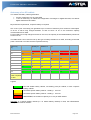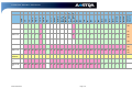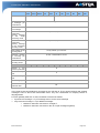
1
Product Guide - A5000 R5.4 – Aastra X series
- CONTENTS 5
THE AASTRA X SERIES ................................................................................................................ 3
5.1
GENERAL DESCRIPTION OF THE RANGE ......................................................................................... 5
5.1.1
Coverage ........................................................................................................................... 5
5.1.2
Benefits for the users ......................................................................................................... 6
5.1.2.1
5.1.2.2
5.1.2.3
5.1.2.4
5.1.2.5
Service integration ....................................................................................................................... 6
Homogeneous design .................................................................................................................. 6
Sizing and connection flexibility ................................................................................................... 6
Remote management .................................................................................................................. 6
High availability of Aastra XD....................................................................................................... 7
5.2
SOFTWARE ARCHITECTURE .......................................................................................................... 8
5.2.1
A common software ........................................................................................................... 8
5.3
HARDWARE ARCHITECTURE ....................................................................................................... 11
5.3.1
Cabinets, power supplies and motherboards .................................................................. 11
5.3.2
Common cards for Aastra XS, XL, XD ............................................................................ 11
5.3.3
Maximum distance for connecting analogue and digital phones ..................................... 13
5.3.4
Aastra XS ......................................................................................................................... 14
5.3.4.1
5.3.4.2
5.3.4.3
5.3.4.4
5.3.4.5
5.3.4.6
5.3.4.7
5.3.4.8
5.3.5
Mechanic design ........................................................................................................................ 14
Expansion slots.......................................................................................................................... 14
Inputs/outputs ............................................................................................................................ 14
UCV2S/EXT2S motherboard ..................................................................................................... 15
Expansion cabinet ..................................................................................................................... 16
Position of the cards .................................................................................................................. 17
Power supply ............................................................................................................................. 18
Autonomy................................................................................................................................... 19
Aastra XS12 ..................................................................................................................... 22
5.3.5.1
5.3.5.2
5.3.5.3
5.3.5.4
5.3.5.5
5.3.5.6
5.3.5.7
5.3.5.8
5.3.6
Mechanic design ........................................................................................................................ 22
Expansion slots.......................................................................................................................... 22
Inputs/outputs ............................................................................................................................ 22
UCV2S/EXT2S12 motherboard ................................................................................................. 23
Expansion cabinet ..................................................................................................................... 23
Position of the cards .................................................................................................................. 24
Power supply ............................................................................................................................. 25
Autonomy................................................................................................................................... 26
Aastra XS6 ....................................................................................................................... 27
5.3.6.1
5.3.6.2
5.3.6.3
5.3.6.4
5.3.6.5
5.3.6.6
5.3.6.7
5.3.6.8
5.3.7
Mechanic design ........................................................................................................................ 27
Expansion slots.......................................................................................................................... 27
Inputs/outputs ............................................................................................................................ 27
Expansion cabinet ..................................................................................................................... 28
UCV2S/EXT2S6 motherboard ................................................................................................... 28
Position of the cards .................................................................................................................. 29
Power supply ............................................................................................................................. 30
Autonomy................................................................................................................................... 30
Aastra XL ......................................................................................................................... 31
5.3.7.1
5.3.7.2
5.3.7.3
5.3.7.4
5.3.7.5
5.3.7.6
5.3.7.7
5.3.7.8
5.3.8
Mechanic design ........................................................................................................................ 31
Expansion slots.......................................................................................................................... 31
Inputs/outputs ............................................................................................................................ 32
UCV2L motherboard .................................................................................................................. 32
Expansion cabinet ..................................................................................................................... 33
Position of the cards .................................................................................................................. 34
Power supply ............................................................................................................................. 36
Autonomy................................................................................................................................... 37
Aastra XD......................................................................................................................... 41
5.3.8.1
5.3.8.2
5.3.8.3
5.3.8.4
5.3.8.5
5.3.8.6
5.3.8.7
5.3.8.8
5.3.8.9
BPS0121AENAA01
Mechanic design ........................................................................................................................ 41
Expansion slots.......................................................................................................................... 42
Inputs/outputs ............................................................................................................................ 42
UCV2D motherboard ................................................................................................................. 43
Expansion cabinet ..................................................................................................................... 44
IUCV2D card.............................................................................................................................. 44
Position of the cards .................................................................................................................. 46
Power supply ............................................................................................................................. 49
Autonomy................................................................................................................................... 50
Page 1/74
Product Guide - A5000 R5.4 – Aastra X series
5.3.9
Duplicated services of the AXD ....................................................................................... 51
5.3.9.1
5.3.9.2
5.3.9.3
5.3.9.4
5.3.9.5
5.3.9.6
Duplicating the power supply modules ...................................................................................... 51
Duplicating the motherboards .................................................................................................... 51
Duplicating the integrated Call Distribution Service ................................................................... 53
Duplicating the voice mail system .............................................................................................. 53
Duplicating the integrated billing services .................................................................................. 53
Duplicating connections to the IP, LAN or WAN network ........................................................... 54
5.4
INTEGRATED SERVICES ON THE MOTHERBOARD........................................................................... 55
5.4.1
Native IP port ................................................................................................................... 55
5.4.2
Using the ETH2 port ........................................................................................................ 55
5.4.3
Separating administration / user flows ............................................................................. 55
5.4.3.1
5.4.3.2
Securing the IP link - Double attachment ................................................................................... 56
Mirroring port – Mirror function................................................................................................... 57
5.4.4
Download via ISDN .......................................................................................................... 57
5.4.5
Integrated buffer .............................................................................................................. 58
5.4.6
i-Button dongle ................................................................................................................. 58
5.4.7
DECT synchronisation ..................................................................................................... 59
5.4.8
Fax and Modem transmission over IP ............................................................................. 60
5.4.9
Integrated clients/servers ................................................................................................. 61
5.5
INTEGRATED CALL DISTRIBUTION SERVICES................................................................................. 62
5.5.1
Call distribution ................................................................................................................ 62
5.5.2
Integrated services .......................................................................................................... 62
5.5.3
User-friendly start-up and administration ......................................................................... 63
5.5.4
Capacity of the functions integrated into the Aastra range .............................................. 63
5.5.4.1
5.5.4.2
5.5.4.3
New 4GB Compact Flash .......................................................................................................... 63
Sizing of the voice services........................................................................................................ 64
Optimising and checking memory space capacities .................................................................. 66
5.6
ADMINISTRATION TOOLS ............................................................................................................ 67
5.6.1
Aastra Management Portal .............................................................................................. 67
5.6.2
AM 7450........................................................................................................................... 68
5.7
DEPLOYMENT CONDITIONS OF THE AASTRA X SERIES ................................................................. 69
5.7.1
Environment and premises .............................................................................................. 69
5.7.1.1
5.7.1.2
5.7.1.3
5.7.1.4
Location ..................................................................................................................................... 69
Environment............................................................................................................................... 69
Space ........................................................................................................................................ 70
Electrical power supply .............................................................................................................. 70
5.7.2
Installation constraints ..................................................................................................... 71
5.8
DIMENSIONING AND PROCESSING CAPACITY ................................................................................ 71
5.9
AVAILABILITY RATE OF THE AASTRA HARDWARE COMPONENTS ..................................................... 72
5.9.1
Automatic restart .............................................................................................................. 73
5.9.2
Backup and restitution duration ....................................................................................... 73
5.10
POWER CONSUMPTION OF CARDS AND MOTHERBOARDS .......................................................... 73
5.11
HEAT EMISSION - ESTIMATION OF THE POWER EMITTED BY THE AX SERIES ............................... 74
5.12
NOISE COMING FROM AX SERIES............................................................................................ 74
BPS0121AENAA01
Page 2/74
Product Guide - A5000 R5.4 – Aastra X series
5 THE AASTRA X SERIES
Aastra offers a range of universal iPbx. The Aastra X Series is made of a homogeneous architecture
that can, be easily upgraded, by adding hardware and software components.
This range is homogeneous and flexible. It is designed for 4 to 704 traditional subscribers and 500 IP
subscribers. It meets requirements of traditional and ToIP markets, as based on a single software
application and a unified infrastructure.
All communication platforms described in this document shares:
•
•
•
•
the same software release
the same range of associated applications
the same range of traditional, IP, SIP and DECT terminals
the service transparency when connected together in an A5000 network
The main key points of the Aastra X Series are:
Universal use
•
•
•
•
•
•
•
•
A unique iPbx range able to manage from 4 up to 1000 subscribers
Capacity can be extended easily (no need to change the hardware).
The hardware is unified across the whole range. Cards could be hot-plugged.
All terminal types are managed: analogue, digital, IP, DECT, Softphone, etc.
It is compatible with all network types: ISDN, analogue and IP networks, tie-line, etc.
Universal installation: rack mounting, wall mounting, etc.
The engineering rules are simplified and the slots are general-purpose slots.
The proposed universal connectors are the RJ45 and USB port (connectors available on the
front panel).
Capacity:
•
•
•
•
•
A hardware platform for connecting 704 traditional subscribers and up to 500 IP subscribers in
only 24U, thanks to 16-extension cards.
Telephony software from the last generation providing 500 functions.
A high level of services is proposed, as voice mail (IVB), interactive voice servers (IVS),
broadcasting of synchronised announcement, Ethernet port, ISDN remote management’s
component and integrated buffer are embedded in the motherboard.
Networking features able to create a virtual telephony network (with Aastra 5000 Server) for
up to 150,000 subscribers.
Performance is at its maximum in full IP, hybrid IP and /traditional environments.
Openness:
•
•
•
•
Evolution to telephony over IP and convergent services.
Compatibility with the existing cards and terminal portfolio.
Compatibility with the most widely accepted standards: SIP, CSTA, TAPI, SNMP, XML, LDAP,
QSIG, etc.
Integration into any existing IS installation, without any impact on the hardware or ip-network
architecture.
BPS0121AENAA01
Page 3/74
Product Guide - A5000 R5.4 – Aastra X series
Scalability:
•
•
•
Smooth architecture’s migration, from traditional telephony to full IP, from single site to multisite.
Size’s expansion: the same software to manage from 4 and 1000 subscribers; hardware
easily expandable (cards, cabinets, VoIP)
Level of Service’s evolution: integrated services for basic needs, external application for
business oriented needs.
Security:
•
•
•
•
•
administration interface on https
OS hardening for both call server and gateway
Downloading secured through automatic fallback mechanisms in case of failure.
Networking secured through load-balancing mechanisms between systems, through security
server on the data network, etc.
Duplication of the motherboard and power supply on the AXD gateway.
Ergonomic design:
•
•
•
Simplified administration and deployment as administration is the same for the whole range
and thanks to availability of deployment tools.
The embedded IP access point makes management easier.
Remote management of the new platforms is entirely available through ISDN or IP.
The Aastra X Serie’s range is made of gateways with different capacities:
•
•
•
Aastra XS, XS12, and XS6 from 4 up to 112 traditional subscribers, up to 500 IP/SIP
subscribers (could be used for security: dual homing, etc.)
Aastra XL, from 50 up to 640 traditional subscribers, and up to 500 IP/SIP subscribers
Aastra XD, from 50 up to 704 traditional subscribers, and up to 500 IP/SIP subscribers;
available in two modes: simplex and duplex (motherboard’s duplication) and duplicated power
supply
BPS0121AENAA01
Page 4/74
Product Guide - A5000 R5.4 – Aastra X series
5.1
General description of the range
5.1.1
Coverage
Aastra XS is designed for the 4 to 112 users’ market. This Aastra XS is also available in two smaller
models: Aastra XS12 with expansion options (maximum of 12 traditional subscribers) and Aastra XS6
with no expansion options.
Aastra XL is designed to manage 200 traditional subscribers in one cabinet. It manages up to 640
traditional subscribers thanks to the addition of two expansion cabinets.
Aastra XD is designed to manage 200 traditional subscribers in one cabinet. It manages up to 704
traditional subscribers thanks to the addition of two expansion cabinets.
These iPbx can be fitted with a broad range of expansion cards, which can be optimally configured to
meet customer’s requirements.
It must be stated that the previous dimensioning of physical line capacities (traditional subscribers)
must be completed by IP/SIP or DECT subscribers’ capacities. Up to 500 IP subscribers can be
declared on AXS/L/D (for example: ip-subscriber’s security with dual homing, etc.).
These platforms are able to provide TDM/IP Media Gateways services as they can deal with 5 T2 and
160 VoIP simultaneously (they provide a transit capacity of about 1,000 terminals).
Note: The capacities given above correspond to market targets. For more information, refer to the
section "Design and Processing Capacity".
BPS0121AENAA01
Page 5/74
Product Guide - A5000 R5.4 – Aastra X series
5.1.2
Benefits for the users
This section describes the benefits for users/administrators.
5.1.2.1 Service integration
The Aastra X Series increases its service integration.
The following components are embedded in the Linux (UCV2) motherboard of the Aastra XS, XL, and
XD:
•
•
•
•
•
•
•
•
•
•
A component for remote management via ISDN
An Ethernet port for IP connection
One USB ports for data backup
A Voice mail system, with single answering machine, films and announcements
An IVS (license needed)
An integrated e-Voicemail service (licence needed)
An integrated buffer
A Web administration via secured HTTPS connection: Aastra Management Portal (AMP)
A SIP access point
5 languages
5.1.2.2 Homogeneous design
The iPbx of the range have the same width (19'' standard) and mechanics. Colours and materials are
the same too.
5.1.2.3 Sizing and connection flexibility
Aastra XS, XL and XD are highly flexible in terms of size, thanks to the current range of expansion
cards (8-extension or16extension modularity) have been added.
Moreover, the connectors for the expansion cards are in RJ45 format. RJ45-type connectors allow
integration into the common switch panels.
The design rules are reduced to the minimum to simplify the deployment and management of the
gateways:
•
•
•
Physical Subscriber cards can be fitted in any slot.
Network cards can be fitted in any slot in the main cabinet.
Co-processor cards have six possible slots.
Most of the cards are hot-plug cards.
5.1.2.4 Remote management
These platforms can be fully managed from a remote location; this means that a remote administrator
can:
•
•
•
•
Know the status of the platforms,
Download a new software application (firmware, announcements and on-hold messages
Configure all Aastra X Series’ services, etc.
Back-up and Restore configuration
BPS0121AENAA01
Page 6/74
Product Guide - A5000 R5.4 – Aastra X series
Remote management can be performed through:
•
•
ISDN, thanks to the integrated HSCX component
IP, in secured HTTPS administration through Aastra Management Portal. This interface,
therefore, replaces the VT100 and allows remote access to the configuration’s services,
through a simple web browser.
5.1.2.5 High availability of Aastra XD
Reliability and availability:
A distinction must be made between system reliability and availability:
•
•
Reliability is defined as the Mean Time Between Failures (MTBF).
Availability is defined as the Mean Time To Repair (MTTR).
High availability of the AXD:
Availability of telephony services may be affected by the following elements:
•
•
Hardware: lighting, CPU problems (capacitor failure, microprocessor failure, etc.), ageing of a
component
Software: bugs
• External links: operator/PSTN carrier link disruptions, IP network (LAN, WAN) failure
• Network reliability: problem of voice quality, viruses, hackers
• Environment: battery, humidity, heat
• Human errors
AXD offers a high level of availability rate of 99.999% in duplex mode.
The table below shows, for each element that affects availability, the solutions brought in by AXD in
duplex mode in order to provide high availability to both traditional subscribers and IP subscribers.
Type of element
Availability for traditional subscribers
Hardware
Duplication
of
the motherboard
Duplication of integrated services
Software
"Watchdog"
Logbook, traces
External links
Operator
access
load-balancing Duplicated IP access point
(ISDN, analogue and SIP)
Network reliability
In case of IP network failure, the Dedicated real-time call processing,
traditional and DECT terminals will QoS, Dual Homing, CAC,
continue working
VoIP
load
balancing,
Dual homing for digital phones
Firewall compatibility
Environment
Duplication
battery
Human errors
Certification and procedures, training
of
Additional
availability
subscribers
for
IP
software
power
supply
and
This duplex mode operation is optional; AXD can also work in simplex mode. In this case, none of its
elements is duplicated, except for the fans of the power supply.
BPS0121AENAA01
Page 7/74
Product Guide - A5000 R5.4 – Aastra X series
5.2
Software architecture
5.2.1
A common software
With its special software which is the same for the entire range, the Aastra X Series provides a
special benefit which distinguishes it from others.
Thanks to this software, associated servers developed by Aastra France or its partners are compatible
to the whole Aastra X Series.
The Aastra 5000 software has the following characteristics:
•
•
It is a modular software solution.
It provides over 500 telephony services for companies, including:
• Call processing:
- Outgoing call services, such as abbreviated numbers, call by name,
emergency numbers, and call restriction, least-cost routing
- Incoming call services, such as forwarding, call filtering, Intercom function
- Services during calls, such as recovery after interruption, transfer and
conference.
- ACD type call distribution services, with longest idle time distribution, multigroup distribution, assistance hunt groups, calendar management
•
•
•
Added-value functions, such as:
- Directory management (up to 3000 records)
- Computer Telephony Interfacing services. Aastra integrates, in the core of its
software, CSTA or VTI XML’s interfaces and an external application interface
(EAI) for vertical applications used in hospitals and hotels/motels, and a TAPI
interface too (option).
- Mobility (DECT, Wi-Fi, DISA, Virtual Desking, etc.)
- Network administration with the AM 7450 management centre.
• Authentication functions
A wide range of PSTN operator/ IP trunk carrier accesses
Multi-site management
BPS0121AENAA01
Page 8/74
Product Guide - A5000 R5.4 – Aastra X series
Applications that enhance the Aastra range include:
•
Aastra Communication Portal, comprising the following services, amongst others:
• The Contact Centre: ACP Contact Center
• The VoIP and Text To Speech server: ACP IVR
• The voice conference server: ACP IP Conference Bridge
• The ACP Web Attendant or CTI attendant console application
• The TWP CTI services for
o a universal dialling
o a universal directory multi-connector: LDAP, SQL, Notes, Exchange, Outlook
o an Intranet directory
o a customisable record-display application
o a telephone wizard in web format
o a remote-work management and customised forwarding application
o a subscriber supervision application: presence management
o …
o See ACP Product Guides
•
Mobility
• The M6241 DECT mobility offer and the transmission of alarms to the DECT terminal
with the M7900 solution
• SIP-DECTincluding base stations over IP and our handsets A6xxd or A142d for a full IP
configuration and full IP remote sites
• The AMC (Aastra Mobile Client) offer for Fix Mobile Convergence
• The voice mail and unified messaging systems with interactive voice server function:
• Integrated voice mail system with 8 simultaneous accesses and its 8-access
interactive voice server option
• Unified Communication Platform (UCP): voice mail system, 64-access interactive
voice server, integrated messaging system, unified messaging system, speech
recognition directory. This unified communication is highly scalable and integrates text
to speech, WAP, Imap4 and LDAP voice recognition technologies.
• Computer Telephony Integration (CTI):
• Web services, desktop messaging service and group work with the Telephony Web
Portal or ACP offer
• TAPI Open Suite
• CSTA interface
• Hotel / hospital solutions:
• Integrated software features for small configurations
• 5 simultaneous languages
• Aastra Hotel Suite used for integration with most front offices in the market, including
billing services, traffic analysis and alarm monitoring
Hotel configuration:
Aastra provides additional features designed for hotels. The following services can be monitored on an
operator console or a digital terminal
•
•
•
•
•
room status - occupied or free,
check-in and check-out
wake-up function
credit charging and bill’s printouts
lamp message control for message notification
…
Customers are notified by a message lamp on their terminal via the LH16 card.
BPS0121AENAA01
Page 9/74
Product Guide - A5000 R5.4 – Aastra X series
Hospital configuration:
This configuration, similar to the previous hotel configuration, can include specific functions for
hospitals, such as
•
•
•
•
voice guides (announcements)
management of DID (Direct Inward Directory) adapted to patients management
the do not disturb (DND) function for patients during the night
charging patients according to the deposit
The Aastra range provides telephony services to a large variety of user interfaces. The level and
number of features provided by the software depend on the kind of terminal.
The Aastra offer can manage the following terminals:
•
•
•
•
•
•
•
•
•
•
•
•
•
Aastra IP terminals Aastra 5360ip, 5370ip, 5380ip and i740, i760,
Aastra SIP terminals Aastra 6731i, 6751i, 6753i, 6755i, 6757i, 6735i/37i, 6739i. The Aastra
gateways are embedding basically a SIP access point.
SIP Terminals: 3rd party terminals which are compliant to the standard SIP protocol are able
to be managed by the embedded SIP module, module available by default on the Aastra
gateways.
SIP Video Terminals: 3rd party terminals which are compliant to the standard SIP protocol
for both the voice and the video are able to be managed by the embedded SIP module,
module available by default on the Aastra gateways
TM
Aastra BluStar 8000i HD multimedia terminal: the HD multimedia video terminal solution
of the Aastra 5000 solution.
TM
Aastra BluStar for PC SIP Softphone: a SIP softphone client which allows calls to be
made from a PC inside an office, or from outside. Moreover, this application can be integrated
into external environments such as Microsoft Lync.
DECT Terminals: wireless DECT terminals are GAP compliant. They give access to DECT
features through DTMF prefixes.
GSM Mobile Terminals: Aastra Mobile Client (AMC) solution allows to manage up to 500
mobile terminals per Aastra X Series gateway.
Wi-Fi terminals: A340w and A342w.
Analogue terminals: Telephone sets, modems or fax machines. Analogue terminals are used
when the required level of service is limited. Users access most of the Aastra 5000 software
features by dialling a DTMF prefix defined for each service or feature. It is also possible to
connect specific terminals such as hotel terminals with message lamp.
ISDN terminals: Thanks to its S0, S2 interfaces, Aastra can manage ISDN telephone sets
and can interconnect to fax servers and routers. For ISDN, Aastra has improved the voice
quality and developed many value-added services such as CLID and call forwarding.
Aastra digital terminals: Aastra 5370, 5380, Aastra 6753, 6755, 6757 and M7xx. Thanks to
full interactivity between these terminals and the Aastra 5000 software, users have access to
the entire variety of Aastra telephony services through user-friendly interfaces.
Attendant console: This is represented by the i2070 Software Attendant Console application
associated with a digital terminal, the A6757 + expansion keypad ATDC, specifically
configured as an attendant console.
BPS0121AENAA01
Page 10/74
Product Guide - A5000 R5.4 – Aastra X series
5.3
Hardware architecture
5.3.1
Cabinets, power supplies and motherboards
Aastra X Series gateways are made of:
•
A 19’’ cabinet, with a maximum width of 400 mm; it can be integrated in a rack.
•
A power supply (two, optional, in AXD) 110/230V. The power supply pattern and its power
depend on the type of gateway.
•
A UCV motherboard: Hardware Version UCV1 or UCV2:
•
UCV1 is compatible as from R5.1
•
UCV2 is compatible R5.2 SP3,R5.3 SP1 and R5.4
•
•
•
Note: new R5.4 systems include UCV2. On park, the R5.4 is compatible UCV1
(excluding EIP64).
Expansion slots: their number depends on the type of cabinet
Expansion cabinets to add expansion slots: size and number of cabinets depends on the
type of cabinet.
The expansion slots can be optionally equipped with the expansion cards shown below.
5.3.2
Common cards for Aastra XS, XL, XD
The Aastra XS, XS12, XS6, XL and XD gateways are designed as modular multi-service platforms.
Their configuration is personalised and based on the interfaces described below:
Extension cards (Traditional Subscribers):
LA16X-8
Extension card, used for connecting 8 analogue terminals.
LA16X
Extension card, specific to the Aastra range, used for connecting 16 analogue
terminals.
LN16X-8
Extension card, used for connecting 8 digital terminals.
LN16X
Extension card, specific to the Aastra range, used for connecting 16 digital
terminals.
DL8, DL16
Extension card, specific to the Aastra range, used for connecting 8/16 digital
terminals. Cards with power saving setting a timetable for standby (via AMP).
Cards also compatible with R5.1 and R5.2, but without the possibility to activate
the power saving function.
LH8/LH16-8
Extension card used for connecting 8 analogue hotel terminals (Depaepe or
Teledex). It provides the same functions as the LA8 card with the following
supplementary function: switching on / off a message lamp on the terminal (if a
message has been left) terminal
LH16X
Extension card, specific to the Aastra range, used for connecting 16 analogue
hotel terminals (Depaepe or Teledex). It provides the same functions as the LA16X
card with the following additional function: switching on / off a message lamp on
the terminal (if a message has been left)
LM8
Extension card used for connecting 8 traditional subscribers for analogue (4) and
digital terminals (4).
BPS0121AENAA01
Page 11/74
Product Guide - A5000 R5.4 – Aastra X series
Analogue network lines:
LR4
4 analogue network lines. It can also be fitted with tone detection (DTOC) or billing
(FTXA or FTXC) daughter boards.
LI1
This card is used to interconnect 2 private iPBXs through an analogue tie line.
Digital interfaces and ISDN
LD4N/LD4X
4 S0/T0 ISDN interface card used to connect either 2/4-channel DECT base
stations, or ISDN terminals (S0), or an ISDN BRI interface (T0).
LD4/LD4N/LD4X
+ 1 ADPCM16
Adding the ADPCM16 daughterboard allows you to manage four 4-channel DECT
base stations.
LT2
S2/T2 ISDN primary rate or PCM interface.
used to connect either to one primary access of a European ISDN network (32IT)
or an American ISDN network (T1, 24IT), or an S2 bus or a PCM digital link
(S2/T2) channel by channel (CAS Channel Associated Signalling).
Data interfaces
CA1
This card used to connect V24 computer terminals (DTE or DCE) in V10 or V28
mode (RS232C). Its front panel has 4 RJ45 ports used to connect 4 asynchronous
terminals for data transmission (max. speed: 19200 bits/s).
CS1
This card used to connect two X.25 synchronous interfaces in V28 or V10 mode,
thanks to 2 DB25 connectors
PT2
TCP/IP and voice over IP gateway card used for connection to a 10/100Mbits
Ethernet LAN compliant to the IEEE 802.3 specifications (RJ45 port).
This card provides
a "TCP/IP – internal buses" gateway function for signalling
a "voice over IP" gateway function. . It is capable of managing 8, 16 or 32 VoIP
gateway channels through the addition of an optional VoIP daughterboard which
carries out the tasks of speech signal processing.
Service cards
IPS
RJ format card which implements a SIP signalling proxy. The SIP access point can
be activated on either the motherboard or the IPS card. The IPS card must be
used if a Session Border Controller (SBC) is required.
Daughter Boards
ADPCM16
EIP 4/8/32/64
VOIP 8/16/32
BPS0121AENAA01
This daughterboard is used to increase from two to four simultaneous
communications on the DECT base stations connected to the UCV2S. Up to 4
DECT base stations can be connected to the motherboard. Fitting the optional
ADPCM16 card on the motherboard makes it possible to manage by default the
four-channel DECT base stations and the handover function between these base
stations,
so
you
do
not
need
to
buy
an
LD4
card.
For AXS
EIP boards allow managing the RTP flows. They have more functionalities than
the VOIP boards (below), such as the T38 fax.
The UCV motherboard can be fitted with two VoIP daughterboards available in
different formats: 4, 8, 32 or 64 voice channels: EIP4, EIP8, EIP32 and EIP64
(attention, EIP64 requires hardware version of UCV2 motherboard). Possible
configurations: 4, 8, 12, 16, 32, 36, 40, 64 and 68, 72, 96 and 128 simultaneous
calls
The PT2 card can be fitted with one VoIP daughterboard available in three formats
with 8, 16 or 32 voice channels
Page 12/74
Product Guide - A5000 R5.4 – Aastra X series
5.3.3
Maximum distance for connecting analogue and digital phones
The maximum distance for connecting Aastra digital phones with LN16X or LN16X-8 cards is:
•
•
1400 m with cable Cat 4 / 10 or 5 / 10 mm
1800 m with cable cat 6 / 10 mm
The maximum distance for connecting Aastra analogue phones (iPbx – set distance) is:
•
•
•
1500 m with cable cat 5 / 10 mm
1600 m with cable cat 6 / 10 mm
2000 m with cable 8 / 10 mm
BPS0121AENAA01
Page 13/74
Product Guide - A5000 R5.4 – Aastra X series
5.3.4
Aastra XS
The Aastra XS platform is a polyvalent and scalable solution. In its default configuration, it has 8
analogue subscribers, 8 digital subscribers, 2 T0, 4 T0/S0, 500 directory records, 500 voice mail
boxes and 8 IVS accesses.
•
•
•
As a polyvalent solution, it consists of telephony solutions with highly advanced, fully
integrated call distribution functions (voice mail interactive voice server) going to telephony
over IP.
Aastra XS is part of the Aastra solution range (Web services integration with TWP, DECT,…).
It manages by default all terminal types: analogue, digital, SIP, DECT and IP.
5.3.4.1 Mechanic design
This cabinet is adapted to 19" racks using brackets. It can also be simply placed on a desk or on the
ground. Finally, it can be mounted on a wall, vertically on a wall adapter.
Width: 440 mm or 19 ‘’
Height: 89 mm or 2U
Depth: 400 mm
Weight: 7.5 kg per rack
Plastic front panel
The cabinet may be opened while in operation, since the power supply is streamlined.
If placed on a desk, a CPU and a PC console may be superimposed in the XS cabinet.
5.3.4.2 Expansion slots
The cabinet has three expansion slots capable of receiving any type of card, equipment cards, or
processor cards.
Those expansion cards are connected using the backpanel which is part of the basic cabinet.
When an expansion slot is not in use, it can be closed using a specific cover.
5.3.4.3 Inputs/outputs
The cabinet provides the following inputs/outputs:
•
•
•
•
•
•
•
•
•
1 DB9 connector for the operating console and debug link
1 RJ45 socket for connecting external on-hold music
3 RJ45 sockets for connecting Ethernet 10/100 BASE-TX
2 RJ45 sockets for DECT synchronisation ports
1 DB25 connector for alarms and remote controls
6 RJ45 for network connections: 2 T0, 4T0/S0
16 RJ45 for traditional subscribers
On UCV1S: 3 USB ports, one master and two slaves. On UCV2S: 2 USB ports, slaves
On UCV1S: 1 RJ45 port for connecting the printer (printer port not active from R5.1). This port
doesn’t exist on UCV2S
At the back of the cabinet 3 connectors are available:
•
•
•
A expansion cabinet connector
A 110/220V 50Hz socket
A connector for battery’s link
BPS0121AENAA01
Page 14/74
Product Guide - A5000 R5.4 – Aastra X series
5.3.4.4 UCV2S/EXT2S motherboard
The basic cabinet contains the UCV2S main card and its expansion card EXT2S, with the
following characteristics:
•
•
•
•
•
•
•
•
•
•
•
•
1 control unit
3 Ethernet 10/100 BASE TX accesses
1 Compact Flash Card (software of the Gateway and terminals, configuration’s data…); the
capacity of the COMPACT flash allows a new software release, a new firmware release of the
IP/SIP terminals to be downloaded and the buffer function (for tickets and billing) to be
integrated and the pictures storage. From version R5.1C, the memory size is 2Go.A new 4Go
compact Flash card is available with R5.4.
1 voice mail system with 8 access points,
2 T0 accesses,
4 accesses configurable in T0 or S0
8 connections for digital terminals
8 connections for analogue terminals
4 3-way conference circuits
4 alarm loop inputs and 4 alarm loop outputs
1 HDLC controller for setting up data communication in a B channel: component for the
software downloading in ISDN mode
1 music-on-hold and announcements
The UCV2S and EXT2S cards provide the interfaces with the following components:
•
•
•
•
•
•
•
•
•
•
•
one debugging console for the UCV2S card (1 DB9 console connector)
an external music source (RJ45 socket)
a general bell
alarm inputs (4)
Ethernet network: the Ethernet 10/100 BASE TX accesses (1 LAN RJ45 connector), allowing
the connection of IP/SIP terminals, SIP Trunk network, i2070, TWP applications in CTI mode
(VTI-XML protocol), administration, etc.
the RUCV card of an expansion cabinet
8 analogue terminal interfaces (the same as the LA16X ones)
8 digital terminal interfaces (the same as the LN16X/DL16 ones)
4 ISDN interfaces configurable in T0 (for network connection) or S0 (connection of S0
terminals
or
of
2-channel
DECT
base
stations)
Note: The AXS cabinet cannot deliver a 40 V remote supply over an S0 link
2 ISDN T0 interfaces
(On UCV1S, there is also a serial printer port (RJ45), but it is not active from R5.1. This port
doesn’t exist on UCV2S)
The UCV2S card provides the following functions:
•
•
•
•
•
•
•
•
data and voice switching
signal processing
voice mail server
defence (management of interface card status)
synchronisation
management of interface cards
remote control of an external device (delivering a voltage of +12V) such as door opener
supervision of the expansion cabinets: The power-on state of an expansion cabinet is
detected by recognising a synchronisation signal. The UCV2S card can force the general
"Reset" of the expansion cabinets, provided they are synchronised.
BPS0121AENAA01
Page 15/74
Product Guide - A5000 R5.4 – Aastra X series
•
locking and unlocking optional software functions. thanks to a component of the "i-Button"
family, which is used to store and authenticate the Aastra gateway ID number (and the
optional software functions)
Power supply of the UCV2S card:
The power supplies are not provided by the backpanel connector, but through a dedicated connector.
The UCV2S card receives the following over this specific connector:
•
•
•
•
+5 V input for its internal circuits
+12V input generally used to supply power to external equipment
- 48 V input for analogue and digital terminals
70V AC input used for the ringing current of analogue terminals
5.3.4.5 Expansion cabinet
An expansion cabinet can be connected to the main cabinet. This expansion cabinet is connected
thanks to a flexible wire, thus allowing the two cabinets to be stacked or to be mounted side by side. In
the case of wall mounting, the expansion cabinet can only be installed beside the basic cabinet.
This expansion cabinet has its own power supply unit and three expansion slots, which only accept
the following cards: LN16, LA16, LA8, LN8, LH8, LM8, LH16, DL8 and DL16.
RUCVS card:
The RUCVS card is installed instead of the UCV2S card in the expansion cabinet. Its main function is
to distribute and monitor the status of the line equipment bus and PCM synchronous trunks at the
positions of the expansion cards. It has an EEPROM memory connected to the UCV2S card through
the connection bus.
It includes a control interface for 3 equipment cards and 7 PCM trunks assigned to the 3 equipment
cards.
BPS0121AENAA01
Page 16/74
Product Guide - A5000 R5.4 – Aastra X series
5.3.4.6 Position of the cards
Basic cabinet
AXS 1.00
P
P
P
AXS 1.01
P
P
P
AXS 1.02
P
P
P
Expansion
cabinet
AXS 2.00-02
NO NO NO NO NO NO NO NO NO NO
NO
NO
NO
Legend:
P
position for synchronisation
R
RECOMMENDED position
I
Any position
NO
Position NOT ALLOWED
BPS0121AENAA01
Page 17/74
8/16
Exclusions
not LX16
16
LH16X-8
16
LN6X-8
16
LA6X-8
16
LH16X
16
LN16
16
DL16
16
LA16
0
IPS
4
LR4
2
LI1
8
LH8
8
LM8
8
DL8
8
LN8X
8/16 8/16 8
4
channel
LD4X
4
channel
LD4(N)
LA8X
8/16
LD4(N)
or
LD4X S0
8/16
LD4(N)
or
LD4X T0
32
LT2 Mic
32
LT2 S2
32
LT2 T2
32
PT2-32
16
PT2-16
8
PT2-8
0
PT2-0
0
CS1
CA1
0
Clock
IT
Product Guide - A5000 R5.4 – Aastra X series
5.3.4.7 Power supply
The ADS 150X is the power supply module of the main cabinet and expansion cabinet of the Aastra
XS.
The mains power supply voltage has the following characteristics:
•
•
•
•
Rated voltage: 115V or 230V compatible with 110V/220V
Tolerances: +/- 10%
Frequency: 50 or 60Hz
Power: 100 W
An optional, external 48V backup battery can be installed (see Autonomy section).
The ADS 150X includes the following functional blocks:
•
A 48V converter providing the following voltages:
• +5V / 5A
• -5V / 0.1A
• +12V / 0.15A. This value does not include the fan power supply current.
• -12V / 0.55A,
• -48V / 0.45A
• 70V / 0.06A ringer
•
A 48V rectifier supplying a 3A current, used as follows:
• 1.35A for the converter,
• 0.9A for the DECT telephone sets and base stations
• 0.75A to charge a 7.5Ah battery for 10 hours (battery will provide 4 hours autonomy to
the AXS).
The rectifier can be connected to 115V or 230V, 50Hz or 60Hz main,
•
A fan supplied with 12 V DC by the converter draws the air into the cabinet through the lefthand side.
Furthermore, the ADS150X generates an alarm in case of failure of the rectifier or of the converter.
BPS0121AENAA01
Page 18/74
Product Guide - A5000 R5.4 – Aastra X series
5.3.4.8 Autonomy
An external backup battery can be installed optionally to protect the cabinet from a power supply
failure and prevent service disruption and the loss of critical data.
The capacity required depends on the configuration.
Note: The same battery can be connected in parallel on the two cabinets of an Aastra XS. In this
case, check that the battery can withstand the charging current (2.5 A per ADS150X (AXS) power
unit).
For a standard configuration the battery must conform to the following specifications:
Battery specifications
Capacity
Number of battery elements
4
Voltage
4 x 12V
(12V per battery element)
Capacity (amp/hours)
2.1 Ah
Battery autonomy
-
Note: batteries of battery cabinets in the Aastra price list have these characteristics.
BPS0121AENAA01
Page 19/74
Product Guide - A5000 R5.4 – Aastra X series
Autonomy of an XS cabinet:
The Aastra XS battery cabinet guarantees:
•
•
2 hours of autonomy for an empty AXS
1 hour of autonomy, no matter the configuration of analogue or digital terminals, but without
digital Aastra 5370 and 5380.
Beyond these requirements, a specific battery is required.
One 15 A.h (13.6 A.h exactly) can guarantee up to 12 hours of autonomy for a maximum consumption
of 50 W. It will be fully charged between 10 and 24 hours. 15 A.h is the maximum capacity
recommended for an AXS.
For the battery to be fully charged in less than 10 hours, the capacity of the installed battery should not
exceed 7.5 A.h.
The table below can be used to look up the type of battery installed on an AXS, according to the total
power consumed out of 48V and the required autonomy.
Autonomy
(h)
Capacity of
batteries in
A.h
24
12.9
15.5
18.0
20.6
23.2
25.8
16
8.8
10.5
12.3
14.0
15.8
17.5
12
6.8
8.2
9.5
10.9
12.2
13,6
8
4.9
5.9
6.9
7.8
8.8
9.8
6
3.9
4.7
5.5
6.3
7.0
7.8
4
2.9
3.5
4.1
4.6
5.2
5.8
2
1.8
2.2
2.5
2.9
3.2
3.6
1
1.2
1.4
1.6
1.9
2.1
2.3
0,5
0.7
0.8
1.0
1.1
1.2
1.4
AXS:
total 25
power required
on 48V
30
35
40
45
50
Legend:
OK with Aastra battery cabinet, one battery pack per cabinet, or with a specific
battery cabinet
OK with a specific battery cabinet – loading: < 10 hours
OK with a specific battery cabinet – loading: > 10 hours
IMPOSSIBLE, the maximum capacity is 15 A.h per AXS cabinet.
Important: If a specific battery cabinet (i.e. no Aastra battery cabinet) is used, the HG4452AA01
battery cable must be ordered.
BPS0121AENAA01
Page 20/74
Product Guide - A5000 R5.4 – Aastra X series
Autonomy of a 2XS cabinet:
The Aastra XS battery cabinet guarantees:
•
•
2 hours of autonomy for an empty AXS
1 hour of autonomy, no matter the configuration of analogue or digital terminals, but without
digital Aastra 5370 and 5380.
Beyond these requirements, a specific battery is required.
One 30 A.h (27.2 A.h exactly) can guarantee up to 12 hours of autonomy for a maximum consumption
of 100 W. It will be fully charged between 10 and 24 hours. 30 A.h is the maximum capacity
recommended for an A2XS.
For the battery to be fully charged in less than 10 hours, the capacity of the installed battery should not
exceed 15 A.h.
The table below can be used to look up the type of battery installed on an A2XS, according to the total
power consumed out of 48V and the required autonomy.
Autonomy
(h)
Capacity of
batteries in
A.h
24
25.8
30.9
36.1
41.2
46.4
51.5
16
17.5
21.1
24.6
28.1
31.6
35.1
12
13.6
16.3
19.0
21.7
24.5
27.2
8
9.8
11.8
13.7
15.7
17.6
19.6
6
7.8
9.4
10.9
12.5
14.1
15.6
4
5.8
6.9
8.1
9.3
10.4
11.6
2
3.6
4.3
5.0
5.7
6.5
7.2
1
2.3
2.8
3.2
3.7
4.2
4.6
0,5
1.4
1.6
1.9
2.2
2.5
2.7
A2XS:
total 50
power
consumed out
of 48V
60
70
80
90
100
Legend:
OK with Aastra battery cabinet, one battery pack per cabinet, or with a specific
battery cabinet
OK with a specific battery cabinet – loading: < 10 hours. Connect the rectifiers in
parallel.
OK with a specific battery cabinet – loading: > 10 hours. Connect the rectifiers in
parallel.
IMPOSSIBLE, the maximum capacity is 15 A.h per AXS cabinet, i.e. 30A.h for an
A2XS.
Important: If a specific battery is used, a special installation wiring is required to place the two power
supply units connected to the batteries in parallel.
BPS0121AENAA01
Page 21/74
Product Guide - A5000 R5.4 – Aastra X series
5.3.5
Aastra XS12
The Aastra XS12 platform is a polyvalent and scalable solution. In its default configuration, it has 8
analogue subscribers, 4 digital subscribers, 4 T0/S0, 500 directory records, 500 voice mail boxes and
8 IVS accesses.
•
•
•
As a polyvalent solution, it consists of telephonic solutions with highly advanced, fully
integrated call distribution functions (messaging system, interactive voice server) going to
telephony over IP.
Aastra XS12 is part of the Aastra solution range (Web services integration with TWP,
DECT…).
It manages by default all terminal types: analogue, digital, SIP, DECT and IP.
5.3.5.1 Mechanic design
This cabinet is adapted to 19" racks using brackets. It can also be laid on the ground or on a desk, by
adding slip-free feet. Finally, it can be mounted on a wall, vertically on a wall adapter.
Width: 440 mm or 19 ‘’
Height: 89 mm or 2U
Depth: 400 mm
Weight: 7.5 kg per rack
Plastic front panel
The cabinet may be opened while in operation, since the power supply is streamlined.
If placed on a desk, a CPU and a PC console may be superimposed in the XS12 cabinet.
5.3.5.2 Expansion slots
The cabinet has three expansion slots capable of receiving any type of equipment or processor cards..
The expansion cards are connected using the backpanel which is part of the basic cabinet.
When an expansion slot is not in use, it can be blocked by means of a specific cover.
5.3.5.3 Inputs/outputs
The following inputs/outputs exist:
•
•
•
•
•
•
•
•
•
1 DB9 connector for the operating console and debug link
1 RJ45 socket for connecting external on-hold music
3 RJ45 sockets for connecting Ethernet 10/100 BASE-TX
2 RJ45 sockets for DECT synchronisation ports
4 RJ45 for network connections: 2 T0, 2T0/S0
1 DB25 connector for alarms and remote controls
12 RJ45 for traditional subscribers
On UCV1S: 3 USB ports, one master and two slaves. On UCV2S: 2 USB ports, slaves
On UCV1S: 1 RJ45 port for connecting the printer (printer port not active from R5.1). This port
doesn’t exist on UCV2S
At the back of the cabinet 3 connectors are available:
•
•
•
A expansion cabinet connector
the 220V 50Hz connection socket
the connector for battery’ link
BPS0121AENAA01
Page 22/74
Product Guide - A5000 R5.4 – Aastra X series
5.3.5.4 UCV2S/EXT2S12 motherboard
The basic cabinet contains the UCV2S main card and its expansion card EXT2S12, with the
following characteristics:
•
•
•
•
•
•
•
•
•
•
1 control unit
3 Ethernet 10/100 BASE TX accesses
1 Compact Flash Card (software of the Gateway and terminals, configuration’s data…); the
capacity of the COMPACT flash allows a new software release, a new firmware release of the
IP/SIP terminals to be downloaded and the buffer function (for tickets and billing) to be
integrated and the pictures storage. From version R5.1C, the memory size is 2Go. A new 4Go
compact Flash card is available with R5.4.
1 voice mailbox with 8 IVB accesses
4 accesses configurable in T0 or S0 or 2-channel DECT base stations
4 connections for digital terminals
8 connections for analogue terminals
4 3-way conference circuits
1 HDLC controller for setting up data communication in a B channel: component for the
software downloading in ISDN mode
announcements, music-on-hold, pre-off-hook, dissuasion message
5.3.5.5 Expansion cabinet
An expansion cabinet can be connected to the main cabinet. This expansion cabinet is connected
thanks to a flexible wire, thus allowing the two cabinets to be stacked or to be mounted side by side. In
the case of wall mounting, the expansion cabinet can only be installed beside the basic cabinet.
This expansion cabinet has its own power supply unit and three expansion slots, which only accept
the following cards: LN16, LA16, LA8, LN8, LH8, LM8, LH16.
RUCVS12 card:
The RUCVS12 card is installed instead of the UCV2S12 card in the expansion cabinet. Its main
function is to distribute and monitor the status of the line equipment bus and PCM synchronous trunks
at the positions of the expansion cards. It has an EEPROM memory connected to the UCV2S12 card
through the connection bus.
It includes a control interface for 3 equipment cards and 7 PCM trunks assigned to the 3 equipment
cards.
BPS0121AENAA01
Page 23/74
Product Guide - A5000 R5.4 – Aastra X series
5.3.5.6 Position of the cards
Basic
cabinet
AXS12
1.00
P
P
P
AXS12
1.01
P
P
P
AXS12
1.02
P
P
P
Expansion
cabinet
AXS 2.0002
NO NO NO NO NO NO NO NO NO NO NO NO NO
Legend:
P
position for synchronisation
R
RECOMMENDED position
I
Any position
NO
Position NOT ALLOWED
BPS0121AENAA01
Page 24/74
8/16
Exclusions
not LX16
16
LH16X-8
16
LN6X-8
16
LA6X-8
16
LH16
16
LN16
16
DL16
LA16
16
IPS
4
LR4
2
LI1
8
LH8
8
LM8
8
DL8
8
LN8X
8/16 8/16 8/16 8/16 8
LD4(N)
or
LD4X T0
LD4(N)
or
LD4X S0
4
channel
LD4X
4
channel
LD4(N)
LA8X
32
LT2 Mic
32
LT2 S2
32
LT2 T2
32
PT2-32
16
PT2-16
8
PT2-8
0
PT2-0
0
CS1
CA1
0
Clock
IT
Product Guide - A5000 R5.4 – Aastra X series
5.3.5.7 Power supply
The ADS 150X is the power supply module of the main cabinet and expansion cabinet of the Aastra
XS12.
The mains power supply voltage has the following characteristics:
•
•
•
•
Rated voltage: a format in 115V compatible with 110V, and a format in 230V compatible with
220V
Tolerances: +/- 10%
Frequency: 50 or 60 Hz
Power: 100 W
An optional, external 48V backup battery can be installed (see Autonomy section).
The ADS 150X includes the following functional blocks:
•
A 48V converter providing the following voltages:
• +5V / 5A
• -5V / 0.1A
• +12V / 0.15A. This value does not include the fan power supply current.
• -12V / 0,55A,
• -48V / 0,45A
• 70V / 0.06A ringer
•
A 48V rectifier supplying a 3A current, used as follows:
• 1.35 A for the converter
• 0.90 A for the DECT telephone sets and base stations
• 0.75 A to charge a 7.5 Ah battery for 10 hours providing 4 hours autonomy to the
system
The rectifier can be connected to 115V or 230V, 50Hz or 60Hz main, according to the type of
ADS150X,
•
A fan supplied with 12V DC by the converter draws the air through into the cabinet the lefthand side.
Furthermore, the ADS150X generates an alarm in case of failure of the rectifier or of the converter.
BPS0121AENAA01
Page 25/74
Product Guide - A5000 R5.4 – Aastra X series
5.3.5.8 Autonomy
An external backup battery can be optionally installed to protect the cabinet from a power supply
failure and prevent service disruption and the loss of critical data.
The capacity required depends on the configuration.
Note: The same battery can be connected in parallel on the two cabinets of an Aastra XS12. In this
case, check that the battery can withstand the charging current (2.5 A per ADS150X (AXS) power
unit).
For a standard configuration the battery must conform to the following specifications:
Battery specifications
Capacity
Number of battery elements
4
Voltage
4 x 12V
(12V per battery element)
Capacity (amp/hours)
2.1 Ah
Battery autonomy
4 hours in the configuration without
backpanel
Note: batteries of battery cabinets in the Aastra price list have these characteristics.
BPS0121AENAA01
Page 26/74
Product Guide - A5000 R5.4 – Aastra X series
5.3.6
Aastra XS6
The Aastra XS6 platform is a polyvalent and scalable solution. In its default configuration, it has 4
analogue subscribers, 2 digital subscribers, 2 T0/S0, 500 directory records, 500 voice mail boxes and
8 IVS accesses.
•
•
•
As a polyvalent solution, it consists of telephonic solutions with highly advanced, fully
integrated call distribution functions (messaging system, interactive voice server) going to
telephony over IP.
Aastra XS6 is part of the Aastra solution range (Web services integration with TWP, DECT…).
It manages by default all terminal types: analogue, digital, DECT, SIP and IP.
5.3.6.1 Mechanic design
This cabinet is adapted to 19" racks using brackets. It can also be laid on the ground or on a desk, by
adding slip-free feet. Finally, it can be mounted on a wall, vertically on a wall adapter.
Width: 440 mm or 19 ‘’
Height: 89 mm or 2U
Depth: 400 mm
Weight: 7.5 kg per rack
Plastic front panel
The cabinet may be opened while in operation, since the power supply is streamlined.
If placed on a desk, a CPU and a PC console may be superimposed in the XS6 cabinet.
5.3.6.2 Expansion slots
The cabinet has three expansion slots capable of receiving any type of equipment or processor cards..
The expansion cards are connected using the backpanel which is part of the basic cabinet.
When an expansion slot is not in use, it can be blocked by means of a specific cover.
5.3.6.3 Inputs/outputs
The following inputs/outputs exist:
•
•
•
•
•
•
•
•
•
1 DB9 connector for the operating console and debug link
1 RJ45 socket for connecting external on-hold music
3 RJ45 sockets for connecting Ethernet 10/100 BASE-TX
2 RJ45 sockets for DECT synchronisation ports
2 RJ45 for network connections: 2 T0, 2T0/S0
1 DB25 connector for alarms and remote controls
6 RJ45 for traditional subscribers
On UCV1S: 3 USB ports, one master and two slaves. On UCV2S: 2 USB ports, slaves
On UCV1S: 1 RJ45 port for connecting the printer (printer port not active from R5.1). This port
doesn’t exist on UCV2S
At the back of the cabinet 3 connectors are available:
•
•
the 220V 50Hz connection socket
the connector for battery’ link
BPS0121AENAA01
Page 27/74
Product Guide - A5000 R5.4 – Aastra X series
5.3.6.4 Expansion cabinet
The AXS6 does not allow connecting an expansion cabinet.
5.3.6.5 UCV2S/EXT2S6 motherboard
The basic cabinet contains the UCV2S main card and its expansion card EXT2S6, with the
following characteristics:
•
•
•
•
•
•
•
•
•
•
1 control unit
3 Ethernet 10/100 BASE TX access
1 Compact Flash Card (software of the Gateway and terminals, configuration’s data…); the
capacity of the COMPACT flash allows a new software release, a new firmware release of the
IP/SIP terminals to be downloaded and the buffer function (for tickets and billing) to be
integrated and the pictures storage. From version R5.1C, the memory size is 2Go. A new 4Go
compact Flash card is available with R5.4.
1 voice mailbox with 8 IVB accesses
2 accesses configurable in T0 or S0 or 2-channel DECT base stations
2 connections for digital terminals
4 connections for analogue terminals
4 3-way conference circuits
1 HDLC controller for setting up data communication in a B channel: component for the
software downloading in ISDN mode
Downloading messages : music-on-hold, pre-off-hook, dissuasion message
Power supply of UCV2S cards:
The power supplies are not provided by the backpanel connector, but through a dedicated connector.
The UCV2S6 card receives the following over this specific connector:
•
•
•
•
+5V input for internal circuits
+12V input generally used to supply power to external equipment
- 48V input for analogue and digital terminals
70V AC input for the ringing current of analogue terminals
BPS0121AENAA01
Page 28/74
Product Guide - A5000 R5.4 – Aastra X series
5.3.6.6 Position of the cards
Basic
cabinet
AXS6
1.00
P
P
P
AXS6
1.01
P
P
P
AXS6
1.02
P
P
P
Legend:
P
PRIORITY position for synchronisation
R
RECOMMENDED position
I
Any position
NO
Position NOT ALLOWED
BPS0121AENAA01
Page 29/74
8/16
Exclusions
not LX16
16
LH16X-8
16
LN6X-8
16
LA6X-8
16
LH16
16
LN16
16
DL16
LA16
16
IPS
4
LR4
2
LI1
8
LH8
8
LM8
8
DL8
8
LN8X
8/16 8/16 8/16 8/16 8
LD4(N)
or
LD4X T0
LD4(N)
or
LD4X S0
4
channel
LD4X
4
channel
LD4(N)
LA8X
32
LT2 Mic
32
LT2 S2
32
LT2 T2
32
PT2-32
16
PT2-16
8
PT2-8
0
PT2-0
0
CS1
CA1
0
Clock
IT
Product Guide - A5000 R5.4 – Aastra X series
5.3.6.7 Power supply
The ADS 150X is the power supply module of the main cabinet of the Aastra XS6.
The mains power supply voltage has the following characteristics:
•
Rated voltage: a format in 115V compatible with 110V, and a format in 230V compatible with
220V
• Tolerances: +/- 10%
• Frequency: 50 or 60 Hz
• Power: 100 W
An optional, external 48V backup battery can be installed (optional) (see Autonomy section).
The ADS150X includes the following functional blocks:
•
•
•
A 48V converter providing the following voltages:
• +5V / 5A
• -5V / 0.1A
• +12V / 0.15A. This value does not include the fan power supply current.
• -12V / 0,55A,
• -48V / 0,45A
• 70V / 0.06A ringer
A 48V rectifier supplying a 3A current, used as follows:
• 1.35 A for the converter
• 0.90 A for the DECT telephone sets and base stations
• 0.75 A to charge a 7.5 Ah battery for 10 hours providing 4 hours autonomy to the
system
A fan supplied with 12V DC by the converter draws the air through into the cabinet the lefthand side.
Furthermore, the ADS150X generates an alarm in case of failure of the rectifier or of the converter.
5.3.6.8 Autonomy
An external backup battery can be optionally installed to protect the cabinet from a power supply
failure and prevent service disruption and the loss of critical data.
For a standard configuration the battery must conform to the following specifications:
Battery specifications
Capacity
Number of battery elements
4
Voltage
4 x 12V
(12V per battery element)
Capacity (amp/hours)
2.1 Ah
Battery autonomy
4 hours in the configuration without
backpanel
Note: batteries of battery cabinets in the Aastra price list have these characteristics.
BPS0121AENAA01
Page 30/74
Product Guide - A5000 R5.4 – Aastra X series
5.3.7
Aastra XL
The Aastra XL platform is a polyvalent and scalable solution. In its default configuration, it has 500
directory records, 1000 voice mail boxes and 8 accesses for the IVS:
•
•
•
It consists of telephony solutions with highly advanced, fully integrated call distribution
functions (voice mail, interactive voice server) going to telephony over IP.
Aastra XL is part of the Aastra solution range (Web services integration with TWP, DECT,…).
It manages by default all terminal types: analogue, digital, DECT, SIP and IP.
5.3.7.1 Mechanic design
An Aastra XL is made of one main cabinet and possibly one (version 2XL) or two (version 3XL)
expansion cabinets.
The main cabinet and the expansion cabinets are in 19"-7U metal cabinet in which the subassemblies
required for the functions are inserted.
The cabinets are adapted to 19" racks using brackets. It is also possible to place them on a desk or on
the ground. They can be stacked, but not installed next to each other to prevent blocking the air inlets
located on the left-hand side.
If placed on a desk, a computer and a PC console may be placed upon the AXL cabinet.
Width: 440 mm or 19 ‘’
Height: 310 mm or 7U
Depth: 310 mm
Weight: 15 kg per rack
The main cabinet and expansion cabinets have a common structure:
•
•
•
•
A slot on the right side for the ADS350XL power supply module
1 slot, in the upper part of the cabinet, reserved for the UCV2L main card
2 columns of 7 slots reserved for plug-in expansion cards along the guides on the sides of
the cabinet (RJ45 format)
Openings for air flow and, thus, ventilation of the cabinet elements
5.3.7.2 Expansion slots
The cabinet has 14 expansion slots capable of receiving any type of RJ45 card, equipment, or with
processor. The expansion cards are connected to a backpanel integrated into the basic cabinet.
The expansion cards, common to the entire range, are rackable on the Aastra XL, as well as the
power supply unit and motherboard. The cabinet does not need to be opened, except in case of
intervention on the backpanel or on the connected motherboard.
When an expansion slot is not in use, it can be closed by a specific cover.
BPS0121AENAA01
Page 31/74
Product Guide - A5000 R5.4 – Aastra X series
5.3.7.3 Inputs/outputs
The cabinet is available in the following format: RJ45 outputs
The following inputs/outputs exist on the front panel of each UCV2L motherboard:
•
•
•
•
•
•
•
•
•
1 DB9 connector for the debug link
1 DB25 connector for alarms and remote controls
1 RJ45 socket for connecting external on-hold music
2 RJ45 sockets for the primary and secondary DECT synchronisation ports
3 Ethernet ports (10/100 base T)
On UCV1L: 3 USB ports, one master and two slaves. On UCV2: 2 USB ports, slaves
control LEDs
the NMI/reset buttons
On UCV1L: 1 RJ45 port for connecting the printer (printer port not active from R5.1). This port
doesn’t exist on UCV2L
The following inputs/outputs exist on each power supply module, on the cabinet’s front
panel:
•
the 220V 50Hz mains connection socket
The following connectors are located at the back side of the cabinet:
•
•
A connector for expansion cabinet
A connector for battery’s link.
5.3.7.4 UCV2L motherboard
The basic cabinet contains the main UCV2L card, including:
•
•
•
•
•
•
•
•
•
1 control unit
3 Ethernet 10/100 BASE TX accesses
1 32-trunk matrix with dynamic addressing
1 voice mail system with 8 access points
1 Compact Flash Card (software of the Gateway and terminals, configuration’s data…); the
capacity of the COMPACT flash allows a new software release, a new firmware release of the
IP/SIP terminals to be downloaded and the buffer function (for tickets and billing) to be
integrated and the pictures storage. From version R5.1C, the memory size is 2Go. A new 4Go
compact Flash card is available with R5.4.
8 3-way conference circuits
4 alarm loop inputs and 4 alarm loop outputs
1 HDLC controller for setting up data communication in a B channel
1 voice prompt and synchronised announcements (on-hold, pre-off-hook)
The UCV2L card provides the interfaces with the following components:
•
•
•
•
•
•
•
one debugging console for the UCV2L card (1 DB9 console connector)
On UCV1L: 1 RJ45 port for connecting the printer (printer port not active from R5.1). This port
doesn’t exist on UCV2L
an external music source (RJ45 socket)
a general bell
alarm inputs (4)
Ethernet network: Ethernet 10/100 BASE TX accesses (1 LAN RJ45 connector), allowing the
connection of IP/SIP terminals, SIP Trunk network, i2070, TWP applications in CTI mode (VTIXML protocol), administration, etc.
the RUCV card of an expansion cabinet
BPS0121AENAA01
Page 32/74
Product Guide - A5000 R5.4 – Aastra X series
The UCV2L card provides the following functions:
•
•
•
•
•
•
•
•
•
data and voice switching
signal processing
voicemail server
defence (management of interface card status)
synchronisation
management of interface cards
remote control of an external device (delivering a voltage of +12V) such as a door opener
supervision of the expansion cabinets: The power-on state of an expansion cabinet is
detected by recognising a synchronisation signal. The UCV2L card can force the general
"Reset" of the expansion cabinets, provided they are synchronised.
Locking and unlocking optional software functions, thanks to a component of the "i-Button"
family, which is used to store and authenticate the Aastra ID number (and the optional
software functions)
Power supply of the UCV2L card:
The UCV2L card receives the following on the backpanel connector (J1):
•
•
•
•
+5V input for its internal circuits
+12V input generally used to supply power to external equipment
- 48V input for analogue and digital terminals
70V AC input for the ringing current of analogue terminals
The UCV2L card includes a 2.4V and 80mAh NiMH battery responsible for:
•
•
storing the contents of the internal memory for approximately 2 months
back-up power supply for the internal clock
5.3.7.5 Expansion cabinet
Two expansion cabinets can be connected to the main cabinet. These expansion cabinets are
connected thanks to a flexible wire, thus allowing the two cabinets to be stacked or to be mounted side
by side.
The expansion cabinets have their own power supply unit and 14 expansion slots each, which only
accept the following cards: LA8X, LN8X, LH8, LH16, LN16, LA16, DL8 and DL16.
RUCVL card:
The RUCVL card is installed instead of the UCV2L motherboard and in the same position as the
UCV2L card in the expansion cabinet. Its main function is to distribute and monitor the status of the
line equipment bus and PCM synchronous trunks in the positions of the expansion cards. It holds an
EEPROM memory connected to the UCV2L card through the connection bus.
It includes a control interface for 14 equipment cards and 7 PCM trunks.
BPS0121AENAA01
Page 33/74
Product Guide - A5000 R5.4 – Aastra X series
2
4
16
16
16
16
16
16
16
16
LI1
LR4
IPS
LA16
DL16
LN16
LH16
LA16X-8
LN16X-8
LH16X-8
Exclusions 8/16
not LX16
8
LH8
8
LM8
8
DL8
8
LN8X
32
32
LT2 S2
LT2 Mic
32
LT2 T2
32
8
PT2-8
PT2-32
0
PT2-0
16
0
CS1
PT2-16
0
CA1
Clock
IT
LD4(N)
or 8/16
LD4X T0
LD4(N)
or 8/16
LD4X S0
4
channel 8/16
LD4X
LA8X
8
5.3.7.6 Position of the cards
Basic
cabinet
AXL 1.00 H0
#8
P
P
P
R
R
R
R
R
R
R
1,00
1.08
AXL 1.01 H1
#9
P
P
P
R
R
R
R
R
R
R
1,01
1.09
AXL 1.02 H2
#10
P
P
P
R
R
R
R
R
R
R
1,02
1.10
AXL 1.03 H3
#11
P
P
P
R
R
R
R
R
R
R
1,03
1.11
AXL 1.04 H4
#12
P
P
P
R
R
R
R
R
R
R
1,04
1.12
AXL 1.05 H5
#13
P
P
P
R
R
R
R
R
R
R
1,05
1.13
AXL 1.06
R
R
R
R
R
R
R
R
AXL 1.07
R
R
R
R
R
R
R
R
AXL 1.08
R
R
R
R
NO R
R
R
R
R
R
R
R
R
1,00
1.08
AXL 1.09
R
R
R
R
NO R
R
R
R
R
R
R
R
R
1,01
1.09
BPS0121AENAA01
Page 34/74
16
16
16
16
16
16
16
LA16
DL16
LN16
LH16
LA16X-8
LN16X-8
LH16X-8
Exclusions 8/16
not LX16
16
IPS
4
LR4
2
LI1
8
LH8
8
LM8
32
LT2 Mic
8
32
LT2 S2
DL8
32
LT2 T2
8
32
PT2-32
LN8X
16
PT2-16
8
PT2-8
0
PT2-0
0
CS1
CA1
Clock
0
IT
LD4(N)
or 8/16
LD4X T0
LD4(N)
or 8/16
LD4X S0
4
channel 8/16
LD4X
LA8X
8
Product Guide - A5000 R5.4 – Aastra X series
AXL 1.10
R
R
R
R
NO R
R
R
R
R
R
R
R
R
1,02
1.10
AXL 1.11
R
R
R
R
NO R
R
R
R
R
R
R
R
R
1,03
1.11
AXL 1.12
R
R
R
R
NO R
R
R
R
R
R
R
R
R
1,04
1.12
AXL 1.13
R
R
R
R
NO R
NO R
R
R
R
R
R
R
R
1,05
1.13
Expansion
cabinet
AXL 2.0013
NO NO NO NO NO NO NO NO NO NO NO NO NO NO NO NO NO NO NO
AXL 3.0013
NO NO NO NO NO NO NO NO NO NO NO NO NO NO NO NO NO NO NO
Legend:
P
PRIORITY position for synchronisation
R
RECOMMENDED position
Any position
NO
Position NOT ALLOWED
E
EXCLUSION of 16 IT card. Position vs cards 2, 4, 8, 16 IT
#N
Indicates that the card can be connected in this slot if no LA8, LN8, LM8, LH8, LI1, LR4, PT2(8IT), PT2(16IT), LD4, LD4N card is installed in slot #N.
BPS0121AENAA01
Page 35/74
Product Guide - A5000 R5.4 – Aastra X series
5.3.7.7 Power supply
The ADS350XL is the power supply module of the main cabinet and expansion cabinet of an Aastra
XL.
The mains power supply voltage has the following characteristics:
•
•
•
•
Rated voltage: 120V or 230V compatible with 110V/220V
Tolerances: +/- 10%
Frequency: 50 or 60 Hz
Power: 300W
An optional, external 48V backup battery can be installed (see Autonomy section).
The power supply module includes the following functional blocks:
•
a 48V converter providing the following voltages:
• +5V / 13A and -5V / 0.5A
• +12V / 0.5A and -12 V / 0.25A
• -48 V / 1.9 A (DECT telephone sets and base stations)
• 70V / 0.2A ringer
• 25-50 Hz (symmetrical current)
•
The 48V converter of the ADS350XL provides a 7A voltage that is used as the following :
• On the main cabinet
o 2.1A to feed the converter,
o 2.95A to feed the sets and the DECT stations,
o 1.95A to charge a 16Ah battery for 10 hours (providing 4 hours autonomy)
o Rectifiers of several power supplies can be connected in parallel. The rectifier
can be connected to a 120V or 230V (+/- 10%), 50Hz or 60Hz mains without
configuration,
•
•
On expansion cabinet
o 1A to feed the converter,
o 4A to feed the sets and the DECT stations,
o 2A to charge a 16Ah battery for 10 hours (providing 4 hours autonomy).
o Rectifiers of several power supplies can be connected in parallel. The rectifier
can be connected to a 120V or 230V (+/- 10%), 50Hz or 60Hz mains without
configuration,
2 fans powered by 12V DC issued from the convertor are extraying airflow to the back of the
cabinet.
Furthermore, on AXL, the ADS350XL generates 4 types of alarms in case of failure:
• Rectifier alarm
• Converter alarm
• Fanning alarm
• Temperature alarm
BPS0121AENAA01
Page 36/74
Product Guide - A5000 R5.4 – Aastra X series
5.3.7.8 Autonomy
An external backup battery can be optionally installed, to protect the cabinet from a power supply
failure and prevent service disruption and the loss of critical data. This 19’’ battery cabinet looks like
the system cabinets and is 2U high.
The capacity required depends on the configuration.
Note: The same battery can be connected in parallel on the three cabinets of an Aastra XL. In this
case, check that the battery withstands the charging current (7A per ADS350XL power unit (AXL)).
For a standard configuration the battery must conform to the following specifications:
Battery specifications
Capacity
Number of battery elements
4
Voltage
4 x 12V
(12V per battery element)
Capacity (amp/hours)
17Ah
Battery autonomy
4h on average
Note: batteries of battery cabinets in the Aastra price list have these characteristics.
BPS0121AENAA01
Page 37/74
Product Guide - A5000 R5.4 – Aastra X series
Autonomy of an AXL cabinet:
The Aastra XL battery cabinet guarantees:
•
•
24 hours of autonomy for an empty AXL with a consumption of 16 W maximum.
2 hours of autonomy, no matter the configuration of analogue or digital terminals, but without
digital terminals Aastra 5370 and 5380.
Beyond these requirements, a specific battery is required.
One 40 A.h can guarantee up to 12 hours of autonomy for a maximum consumption of 150 W. It will
be fully charged between 10 and 24 hours. 40 A.h is the maximum capacity recommended for an AXL.
For the battery to be fully charged in less than 10 hours, the capacity of the installed battery should not
exceed 20 A.h.
Autonomy
(h)
Capacity of
batteries in
A.h
24
12.9
25.8
38.7
51.5
64.4
77.3
16
8.8
17.5
26.3
35.1
43.9
52.6
12
6.8
13.6
20.4
27.2
34.0
40.0
8
4.9
9.8
14.7
19.6
24.5
29.4
6
3.9
7.8
11.7
15.6
19.5
23.4
4
2.9
5.8
8.7
11.6
14.5
17.4
2
1.8
3.6
5.4
7.2
9.0
10.8
1
1.2
2.3
3.5
4.6
5.8
6.9
0,5
0.7
1.4
2.1
2.7
3.4
4.1
total 25
power required
on 48V
50
75
100
125
150
AXL:
Legend:
OK with Aastra battery cabinet, one battery pack per cabinet, or with a specific
battery cabinet
OK with a specific battery cabinet – loading: < 10 hours
OK with a specific battery cabinet – loading: > 10 hours
IMPOSSIBLE, the maximum capacity is 40 A.h per AXL cabinet
Important: If a specific battery cabinet (i.e. no Aastra battery cabinet) is used, the HG4452AA01
battery cable must be used.
BPS0121AENAA01
Page 38/74
Product Guide - A5000 R5.4 – Aastra X series
Autonomy of an A2XL cabinet:
The Aastra XL battery cabinet guarantees (per AXL cabinet) 2 hours of autonomy, no matter the
configuration of analogue or digital terminals, but without digital terminals Aastra 5370 and 5380.
Beyond these requirements, a specific battery is required
One 80 A.h can guarantee up to 12 hours of autonomy for a maximum consumption of 300 W. It will
be fully charged between 10 and 24 hours. 80 A.h is the maximum capacity recommended for an
A2XL.
For the battery to be fully charged in less than 10 hours, the capacity of the installed battery should not
exceed 40 A.h.
Autonomy
(h)
Capacity of
batteries in
A.h
24
25.8
51.5
77.3
103.1
128.9
154.6
16
17.5
35.1
52.6
70.2
87.7
105.3
12
13.6
27.2
40.8
54.3
67.9
80.0
8
9.8
19.6
29.4
39.2
49.0
58.8
6
7.8
15.6
23.4
31.3
39.1
46.9
4
5.8
11.6
17.4
23.1
28.9
34.7
2
3.6
7.2
10.8
14.4
18.0
21.6
1
2.3
4.6
6.9
9.3
11.6
13.9
0,5
1.4
2.7
4.1
5.5
6.9
8.2
A2XL:
total 50
power required
on 48V
100
150
200
250
300
Legend:
OK with Aastra battery cabinet, one battery pack per cabinet, or with a specific
battery cabinet
OK with a specific battery cabinet – loading: < 10 hours. Connect the rectifiers in
parallel.
OK with a specific battery cabinet – loading: > 10 hours. Connect the rectifiers in
parallel.
IMPOSSIBLE, the maximum capacity is 40 A.h per AXL cabinet, i.e. 80A.h for a
A2XL
Important: If a specific battery is used, a special installation wiring is required to place the two power
supply units connected to the batteries in parallel.
BPS0121AENAA01
Page 39/74
Product Guide - A5000 R5.4 – Aastra X series
Autonomy of an A3XL cabinet:
The Aastra XL battery cabinet guarantees (per AXL cabinet – 3 battery cabinets) 2 hours of autonomy,
no matter the configuration of analogue or digital terminals, but without digital terminals Aastra 5370
and 5380.
Beyond these requirements, a specific battery is required.
One 120 A.h can guarantee up to 12 hours of autonomy for a maximum consumption of 450 W. It will
be fully charged between 10 and 24 hours. 120 A.h is the maximum capacity recommended for an
A3XL.
For the battery to be fully charged in less than 10 hours, the capacity of the installed battery should not
exceed 60 A.h.
Autonomy
(h)
Capacity of
batteries in
A.h
24
38.7
77.3
116.0
154.6
193.3
232.0
16
26.3
52.6
78.9
105.3
131.6
157.9
12
20.4
40.8
61.1
81.5
101.9
120.0
8
14.7
29.4
44.1
58.8
73.5
88.2
6
11,7
23.4
35.2
46.9
58.6
70.3
4
8.7
17.4
26.0
34.7
43.4
52.1
2
5.4
10.8
16.2
21.6
26.9
32.3
1
3.5
6.9
10.4
13.9
17.4
20.8
0,5
2.1
4.1
6.2
8.2
10.3
12.3
A3XL :
total 75
power required
on 48V
150
225
300
375
450
Legend:
OK with Aastra battery cabinet, one battery pack per cabinet, or with a specific
battery cabinet
OK with a specific battery cabinet – loading: < 10 hours. Connect the rectifiers in
parallel.
OK with a specific battery cabinet – loading: > 10 hours. Connect the rectifiers in
parallel.
IMPOSSIBLE, the maximum capacity is 40 A.h per AXL cabinet, i.e. 120A.h for a
A3XL
Important: If a specific battery is used, a special installation wiring is required to place the two power
supply units connected to the batteries in parallel.
BPS0121AENAA01
Page 40/74
Product Guide - A5000 R5.4 – Aastra X series
5.3.8
Aastra XD
The Aastra XD platform is a polyvalent and scalable solution. In its default configuration, it has 500
directory records, 1000 voice mail boxes and 8 accesses for the IVS:
•
•
•
It consists of telephony solution with highly advanced, fully integrated call distribution functions
(voicemail, interactive voice server) going to telephony over IP.
Aastra XD is part of the Aastra solution (Web services integration with TWP, DECT,…).
It manages by default all terminal types: analogue, digital, DECT, SIP and IP.
5.3.8.1 Mechanic design
An Aastra XD is made of one main cabinet and possibly one (version 2XD) or two (version 3XD)
expansion cabinets.
The main cabinet and the expansion cabinets are in 19"-10U metal cabinet in which the
subassemblies required for the functions are inserted.
The cabinets are adapted to 19" racks using brackets.
In AXD configuration (one single cabinet without expansion), it can be placed on a desk or on the
ground.
If placed on a desk, a CPU and a PC console may be placed upon the AXD cabinet.
In a configuration with an expansion cabinet (AX2D or AX3D), it is advisable to install them in a rack
to avoid any instability. The cabinets should not be placed side by side, to avoid blocking of the air
inlets located on their left side.
Width: 440 mm or 19 ‘’
Height: 443 mm or 10U
Depth: 316 mm
Weight: 15 kg per simplex rack,
18kg per duplex rack
(outside the expansion cards)
The main cabinet and expansion cabinets have a common structure:
•
•
•
•
•
On the right two locations are reserved for two ADS350XD power supply modules.
Three slots located in the upper part of the cabinet:
• The first one is reserved for the IUCV2D interface motherboard used to connect the
motherboards of the main cabinet together (in the expansion cabinet, this slot is free
and equipped with a cover).
• The next two are reserved for the two (active and backup) UCV2D motherboards.
One back panel for connecting all the elements to the two main cards
Two columns of 8 slots are reserved for plug-in expansion cards along the guides on the sides
of the cabinet (RJ45 format).The last row (at the bottom’s bottom) can only receive IPS cards.
There are openings for air flow and, thus, ventilation of the cabinet elements.
BPS0121AENAA01
Page 41/74
Product Guide - A5000 R5.4 – Aastra X series
5.3.8.2 Expansion slots
The cabinet has:
•
•
14 expansion slots designed for any type of RJ45 card, equipment or processor cards.
2 expansion slots designed for IPS or BTX cards.
The expansion cards are connected to a backpanel integrated into the basic cabinet.
The expansion cards, common to the entire Aastra 5000 range, could be plugged on Aastra XD, as
well as the power supply unit and motherboard. The cabinet does not need to be opened, except in
case of intervention on the backpanel or on the connected motherboard.
When an expansion slot is not in use, it can be closed by means of its specific cover.
When an entire column of seven slots is not in use, a column cover is used to close the entire column.
5.3.8.3 Inputs/outputs
The following inputs/outputs are on the IUCV2D interface motherboard’s front panel:
•
•
•
•
•
1 DB9 connector for the operating console
1 RJ45 socket for connecting external on-hold music
2 RJ45 sockets for the primary and secondary DECT synchronisation ports
1 DB25 connector for alarms and remote controls
On UCV1D: 1 RJ45 port for connecting the printer (printer port not active from R5.1). This port
doesn’t exist on UCV2D
The following inputs/outputs exist on the front panel of each UCV2D motherboard:
•
•
•
•
•
1 DB9 connector for the debug link
2 Ethernet ports (10/100 base T)
control LEDs
1 DB25 connector for the parallel port
the NMI/reset buttons
The following inputs/outputs exist on each power supply module, on the cabinet’s front
panel:
•
socket for 220V 50Hz main
The following connector is located at the back side of the cabinet:
•
•
A connector for expansion cabinet
A connector for battery’s link.
BPS0121AENAA01
Page 42/74
Product Guide - A5000 R5.4 – Aastra X series
5.3.8.4 UCV2D motherboard
The basic cabinet contains 1 or 2 (duplex mode) main UCV2D cards, each with:
•
•
•
•
•
•
•
•
•
1 control unit
3 Ethernet 10/100 BASE TX accesses
1 32-trunk matrix with dynamic addressing
1 voice mail system with 8 access points
1 Compact Flash Card (software of the Gateway and terminals, configuration’s data…); the
capacity of the COMPACT flash allows a new software release, a new firmware release of the
IP/SIP terminals to be downloaded and the buffer function (for tickets and billing) to be
integrated and the pictures storage. From version R5.1C, the memory size is 2Go. A new 4Go
compact Flash card is available with R5.4.
8 3-way conference circuits
4 alarm loop inputs and 4 alarm loop outputs
1 HDLC controller for setting up data communication in a B channel
1 integrated answering service
This card exists in RJ45 connection format.
In simplex mode, the UCV2D card provides the same functions as the AXL UCV2L card (see also
4.3.4.4).
The UCV2D card has the following interfaces:
•
•
•
•
one console for testing and debugging the card when it is in a “passive” state (1 DB9 Debug
connector)
Ethernet network: 2 Ethernet 10/100 BASE TX access (LAN RJ45 connector)
interface with RUCV card of an expansion cabinet, located on the back of the cabinet
USB connector for configuration’s backup and restore
The IUCV2D card has the following interfaces:
•
•
•
•
•
one operating and debugging console for the active card (1 DB9 console connector)
a serial printer (RJ45 socket) (printer port not active from R5.1)
an external music source (RJ45 socket)
a general bell
alarm inputs (4)
The i-button for enabling the software functions is located on the IUCV2D motherboard.
Power supply of the UCV2D card:
The UCV2D card receives the following on the backpanel connector (J1):
•
•
•
•
+5V input for its internal circuits
+12V input generally to supply power to external equipment
- 48V input for analogue and digital terminals
70V AC input for the ringing current of analogue terminals
The UCV2D card includes a 2.4V and 80mAh NiMH battery responsible for:
•
•
•
storing the contents of the internal memory for about 2 months
backing up power supply for the internal clock
The battery is soldered onto the circuit and is not interchangeable; when installing the system,
charge the battery for 12 hours
BPS0121AENAA01
Page 43/74
Product Guide - A5000 R5.4 – Aastra X series
UCV2D card daughterboard:
•
Note. In duplex configuration, the number of EIP cards must be duplicated identically on the
two UCV2D motherboards.
5.3.8.5 Expansion cabinet
Two expansion cabinets can be connected to the main cabinet. Each expansion cabinet is connected
thanks to a flexible wire, thus allowing the cabinets to be stacked in a 19’’ rack.
The expansion cabinets have their own redundant ADS350XD power supply units (one or two) and 16
expansion slots each, which only accept the following cards: LA8X, LN8X, LH8, LN16, LA16, LH16X,
DL8 or DL16.
RUCVD card:
The RUCVD card is installed instead of the UCV2D card in the expansion cabinet. There are thus two
RUCVD cards, which provide the duplication of the expansion function. Its main function is to
distribute and monitor the status of the line equipment bus and PCM synchronous trunks at the
positions of the expansion cards.
It includes a control interface for 16 equipment cards and 8 PCM trunks.
5.3.8.6 IUCV2D card
In duplex configuration, the main cabinet of an XD is equipped with two UCV2D cards. The two
UCV2D (active and passive) cards communicate via the IUCV2D card. The IUCV2D card is not
duplicated.
The i-Button dongle
A removable i-button dongle from Dallas Semiconductors (DS-1971) is available on the IUCV2D
motherboard. It is not located on the motherboard as is with other Aastra gateways. It is, therefore,
common to both motherboards.
It is used to store and authenticate the identification number of the Aastra XD. Then it is used for
locking/unlocking optional software functions.
The IUCV2D card supports the external system’s connections:
•
•
•
•
•
•
1 removable i-button circuit for storing the PBX ID number used for disabling and enabling the
optional software functions
1 operating console connector
1 serial port for a printer (printer port not active from R5.1)
1 input for a source of external music
2 synchronisation ports (primary and secondary DECT)
4 alarm inputs and 4 relays (3 remote control relays + one "watchdog" alarm relay each)
Note: If an AXD has been ordered, it is delivered with the corresponding i-button on the IUCV2D card.
A maintenance IUCV2D card is delivered without i-Button.
BPS0121AENAA01
Page 44/74
Product Guide - A5000 R5.4 – Aastra X series
In case of failure of the IUCV2D card:
•
•
The probability of the switch developing a fault is very low, and the only consequence will be
to block communications between the active and passive UCV2D cards. Therefore, service is
not reduced. The duplication operation between the two motherboards will simply stop working
until the card is put back into service or replaced. Once the switch becomes faulty, the active
motherboard sends an alarm notifying the manager that the passive motherboard can longer
be reached.
The probability of the dongle being inaccessible is even lower (due to the connections). The
dongle is not read through the switch but by a simple communication bus: the dongle remains
accessible.
The IUCV2D card can be hot-plugged.
BPS0121AENAA01
Page 45/74
Product Guide - A5000 R5.4 – Aastra X series
5.3.8.7 Position of the cards
8/16
Exclusions
Not LX16
16
LH16X-8
16
LN16X-8
16
LA16X-8
16
LH16
16
LN16
16
DL16
16
LA16
4
LR4
2
LI1
8
LH8
8
LM8
8
DL8
8
LN8
8/16 8/16 8/16 8/16 8
LD4(N)
or
LD4X T0
LD4(N)
or
LD4X S0
4
channel
LD4X
4
channel
LD4(N)
LA8
32
LT2 Mic
32
LT2 S2
LT2 T2
32
IPS
32
PT2-32
16
PT2-16
8
PT2-8
0
PT2-0
0
CS1
CA1
0
Clock
IT
Basic
cabinet
AXD 1.00 H0
#8
P
P
P
R
R
#8
R
R
R
R
R
R
R
R
R
R
R
R
1,00
1.08
AXD 1.01 H1
#9
P
P
P
R
R
#9
R
R
R
R
R
R
R
R
R
R
R
R
1,01
1.09
AXD 1.02 H2
#10
P
P
P
R
R
#10 R
R
R
R
R
R
R
R
R
R
R
R
1,02
1.10
AXD 1.03 H3
#11
P
P
P
R
R
#11 R
R
R
R
R
R
R
R
R
R
R
R
1,03
1.11
AXD 1.04 H4
#12
P
P
P
R
R
#12 R
R
R
R
R
R
R
R
R
R
R
R
1,04
1.12
AXD 1.05 H5
#13
P
P
P
R
R
#13 R
R
R
R
R
R
R
R
R
R
R
R
1,05
1.13
AXD 1.06
R
R
R
R
R
R
R
R
R
R
R
R
R
R
R
R
AXD 1.07
R
R
R
R
R
R
R
R
R
R
R
R
R
R
R
R
AXD 1.08
R
R
R
R
NO R
NO R
R
R
R
R
R
R
R
R
R
R
R
R
R
1,00
1.08
AXD 1.09
R
R
R
R
NO R
NO R
R
R
R
R
R
R
R
R
R
R
R
R
R
1,01
1.09
BPS0121AENAA01
Page 46/74
Product Guide - A5000 R5.4 – Aastra X series
8/16
Exclusions
Not LX16
16
LH16X-8
16
LN16X-8
16
LA16X-8
16
LH16
16
LN16
16
DL16
16
LA16
4
LR4
2
LI1
8
LH8
8
LM8
8
DL8
8
LN8
8/16 8/16 8/16 8/16 8
LD4(N)
or
LD4X T0
LD4(N)
or
LD4X S0
4
channel
LD4X
4
channel
LD4(N)
LA8
32
LT2 Mic
32
LT2 S2
LT2 T2
32
IPS
32
PT2-32
16
PT2-16
8
PT2-8
0
PT2-0
0
CS1
CA1
0
Clock
IT
AXD 1.10
R
R
R
R
NO R
NO R
R
R
R
R
R
R
R
R
R
R
R
R
R
1,02
1.10
AXD 1.11
R
R
R
R
NO R
NO R
R
R
R
R
R
R
R
R
R
R
R
R
R
1,03
1.11
AXD 1.12
R
R
R
R
NO R
NO R
R
R
R
R
R
R
R
R
R
R
R
R
R
1,04
1.12
AXD 1.13
R
R
R
R
NO R
NO NO R
R
R
R
R
R
R
R
R
R
R
R
R
R
1,05
1.13
AXD 1.14
NO NO NO NO NO NO R
NO NO NO NO NO NO NO NO NO NO NO NO NO NO NO NO NO NO NO NO NO 1,05
1.13
AXD 1.15
NO NO NO NO NO NO R
NO NO NO NO NO NO NO NO NO NO NO NO NO NO NO NO NO NO NO NO NO 1,05
1.13
AXD 2.0015
NO NO NO NO NO NO
NO NO NO NO NO NO NO NO NO NO NO NO NO NO R
R
R
R
R
R
R
AXD 3.0015
NO NO NO NO NO NO
NO NO NO NO NO NO NO NO NO NO NO NO NO NO R
R
R
R
R
R
R
Expansion
cabinets
BPS0121AENAA01
Page 47/74
Product Guide - A5000 R5.4 – Aastra X series
Legend:
P
PRIORITY position for synchronisation
R
RECOMMENDED position
Any position
NO
Position NOT ALLOWED
E
EXCLUSION of 16 IT card. Position vs cards 2, 4, 8, 16 IT
#N
Indicates that the equipment’s connexion is possible if no LA8, LN8, LM8, LH8, LI1, LR4, PT2(8IT), PT2(16IT),
LD4, LD4N card is installed in slot N.
BPS0121AENAA01
Page 48/74
Product Guide - A5000 R5.4 – Aastra X series
5.3.8.8 Power supply
The ADS350XD is the power supply module of the main cabinet and expansion cabinet of an Aastra
XD.
Depending on the configuration of the AXD, power is supplied to the cabinets through 1 or 2
ADS350XD (or previously ADS 300XD) power supply modules:
•
For a simplex configuration, only one power supply module is used by the cabinet. A
ventilation system is then added instead of the second power supply module.
• For a simplex configuration with secure power supply, and for a duplex configuration,
two power supply modules – with the same references - are used per cabinet. The power
supply modules then work in load-balancing mode. If one power supply module becomes
faulty, the other one carries the entire load.
Note: On one very server ADS300XD and ADS350XD can’t be mixed.
Two slots on the right side of the cabinet are used to connect two ADS350XD power supply
modules:
•
•
•
Both slots are general-purpose slots, and a power supply module can be fitted or removed
while the cabinet is working, as soon as the other power supply module is working.
One power supply module is enough to carry the load of a cabinet, even within its currently
defined maximum capacities.
When a position is not occupied by a power supply module, a VADS ventilation rack should be
placed there to ensure proper ventilation of the cabinet.
The mains power supply voltage of the ADS350XD has the following characteristics:
•
•
•
•
Rated voltage: 120V or 230V compatible with 110V/220V
Tolerance: +/- 10%
Frequency: 50 or 60 Hz
Power: 300W
An optional, external 48V backup battery can be installed (see Autonomy section).
The two power supply modules include the following functional blocks:
•
a 48V converter providing the following voltages:
• +5V / 15A and -5V / 0.5A
• +12V / 0.5A and -12 V / 0.65A
• -48 V / 1.9 A (DECT telephone sets and base stations)
• 70V / 0.2A ringer
• 25-50 Hz (symmetrical current)
Reminder: The ADS300XD power supply is replaced by the ADS350XD power supply on the new
AXD gateways.
The ADS350XD has the same characteristics as the ADS300XD, except:
•
The 48V converter of the ADS350XD provides a 7A voltage that is used as the following :
• On the main cabinet
BPS0121AENAA01
•
2.1A to feed the converter,
•
2.95A to feed the sets and the DECT stations,
•
1.95A to charge a 16Ah battery for 10 hours (providing 4 hours autonomy)
Page 49/74
Product Guide - A5000 R5.4 – Aastra X series
•
•
Rectifiers of several power supplies can be connected in parallel. The rectifier can
be connected to a 120V or 230V (+/- 10%), 50Hz or 60Hz mains without
configuration,
On expansion cabinet
•
1A to feed the converter,
•
4A to feed the sets and the DECT stations,
•
2A to charge a 16Ah battery for 10 hours (providing 4 hours autonomy).
•
•
Rectifiers of several power supplies can be connected in parallel. The rectifier can
be connected to a 120V or 230V (+/- 10%), 50Hz or 60Hz mains without
configuration,
Rectifiers from several power supplies can be connected in a parallel mode. Without any
configuration the rectifier can be connected to a 120 V Main or a 230V Main (+/- 10%) 50Hz or
60Hz.
2 fans powered by 12V DC issued from the converter are extraying airflow to the back of the
cabinet.
ADS350XD generates 4 types of alarms in case of failure:
• Rectifier alarm
• Converter alarm
• Fanning alarm
• Temperature alarm
5.3.8.9 Autonomy
An external backup battery can be installed optionally to protect the cabinet from a power supply
failure and prevent service disruption and the loss of critical data. This 19’’ battery cabinet looks like
the system cabinets and is 2U high.
The capacity required depends on the configuration.
Note: The same battery can be connected in parallel on the three cabinets of an AXD. In this case,
check that the battery can withstand the charging current (2A per ADS350XD power unit).
For a standard configuration the battery must conform to the following specifications:
Battery specifications
Capacity
Number of battery elements
4
Voltage
4 x 12V
(12V per battery element)
Capacity (amp/hours)
17Ah (1 battery per cabinet)
24 AH (1 battery in parallel on a
A2XD)
38 AH (1 battery in parallel on a
A3XD)
Battery autonomy
4h (average)
Note: batteries of battery cabinets in the Aastra price list have these characteristics.
BPS0121AENAA01
Page 50/74
Product Guide - A5000 R5.4 – Aastra X series
5.3.9
Duplicated services of the AXD
5.3.9.1 Duplicating the power supply modules
Physical description
The main AXD cabinet can receive two ADS350XD power supply modules, although one is enough to
meet the power supply requirement of a cabinet, even if fully charged.
Furthermore, each expansion cabinet can receive two ADS350XD power supply modules.
The power supply modules connected in the main cabinet cannot be used for providing power to an
expansion cabinet and vice versa.
Switchover procedure
When there are two power supply modules in a cabinet, they work in load-balancing mode.
If one power supply module becomes faulty, the other one carries the entire load. This switchover is
transparent for the cabinet’s equipments. Thus, there is no service interruption.
The faulty power supply module must be replaced manually. The faulty power supply module can be
removed without switching-off the Aastra XD (hot-disconnection). Then a working power supply
module is fitted in the empty position, still without switching-off the system (hot-connection). This new
power supply module now shares the load with the first one.
This procedure applies both to the main cabinet and the expansion cabinet.
If the main cabinet is powered off (due to power failure or the disconnection of a source of power
supply), the expansion cabinet(s) stop(s) working.
On the other hand, if an expansion cabinet is powered off, the main cabinet remains operational, but
the absence of expansion cabinet services (subscriber) will highly disturb the system’s level of service.
5.3.9.2 Duplicating the motherboards
The time required to synchronise the two motherboards must be as short as possible. Therefore, the
link between the two motherboards, and also the protocol used, are optimised.
Physical description
The AXD main cabinet can receive two UCV2D motherboards although one is enough to operate the
entire system services.
The expansion cabinets have one or two RUCVD cards instead of a UCV2D card although one is
enough to operate the entire system services.
Switchover procedure
When there are two motherboards in the main cabinet, one is active and the other passive (that is not
used by any service in the system).
When the active motherboard becomes faulty, or is intentionally removed from the cabinet, or if a
switchover is caused by a MMI or the Management Centre, the passive motherboard becomes active.
This takes within 1 and 6 minutes, depending on the configuration; on average this switchover time
will be about three minutes. Therefore, on-going calls are cut, and all the system services lost for this
period of time.
A hardware failure is a degradation of the motherboard’s hardware or software components, resulting
in the complete stop of this motherboard.
A software failure is an anomaly resulting in the system software reboot. It does not lead to a
switchover to the passive motherboard, the active motherboard is simply restarted.
A faulty motherboard must be replaced manually. The faulty Motherboard can be removed without
switching off the system (hot-disconnection). Then a new motherboard is fitted in this position, still
without switching off the system (hot-connection). Finally, this new passive card must be declared
BPS0121AENAA01
Page 51/74
Product Guide - A5000 R5.4 – Aastra X series
through the MMI, so that it can be recognised by the system, and to ensure full synchronisation
between the active motherboard and the new, passive motherboard (software, data, announcements,
IVS, etc.) as soon as possible.
This new motherboard is from now on the system’s passive motherboard, and will become active
during a potential switchover in future, which can be forced through an MMI.
Duplicating the hardware functions
During a switchover, once the passive motherboard has become active and functional, all the
hardware functions become automatically available again, thanks to hardware function’s redundancy
on both motherboards, and thanks to the centralisation of the front panel’s connections on the i-uct
The following functions become available again after switchover:
•
•
•
•
•
•
•
10/100 BaseT IP ports
DECT synchronization port
signal processing auxiliaries (DSP)
4 alarm loop inputs and 4 alarm loop outputs
the HDLC controller for setting up data communication in a B channel
console port
external music port
Data synchronisation
Data synchronisation is performed in real time, to bring the data on the passive board to the same
level as the active board.
This synchronisation guarantees service continuity after switchover, for the following functions:
•
•
•
•
•
Subscriber configuration
Network configuration
Customisation of digital terminals
DECT service
Directory numbers, etc.
Software synchronisation
After each software upgrade on the active motherboard, system and application’s software are
synchronised with the passive motherboard including: version, patch, MMI’s languages, etc.
This synchronisation is done once the new software release has been validated by the Aastra XD or
by the management centre.
This synchronisation guarantees service continuity after switchover, for the following functions:
•
•
•
active software version, system and application
Digital terminal’s languages and MMI’s languages
patches
BPS0121AENAA01
Page 52/74
Product Guide - A5000 R5.4 – Aastra X series
5.3.9.3 Duplicating the integrated Call Distribution Service
The integrated Call Distribution function (integrated IVS, music on hold, spoken announcements) is
duplicated on AXD. In case of switchover, the function is only unavailable during the switchover, and
becomes available again thereafter without any manual intervention.
The Call Distribution service configuration and the associated voice recordings (music, spoken
announcements) are automatically updated on the passive motherboard each time the Call distribution
service is modified by the management centre, or after a new motherboard is added in the system( in
line with the answering service configuration).
Duplicating the IVR
The integrated interactive voice server function is duplicated on AXD.
In case of switchover, the function is only unavailable during the switchover, and becomes available
again thereafter without any manual intervention.
The IVR configuration and voice recordings are automatically updated on the passive motherboard
each time the call distribution service is modified by the management centre, or after a new
motherboard is added in the system (in line with the answering service configuration).
For an external IVS (an answering service application outside of the AXD) see the functional definition
of the application to find out the duplication level.
5.3.9.4 Duplicating the voice mail system
Integrated voicemail (IVB)
All messages left and also the voice signatures and customisable greeting messages are duplicated.
In case of a fault on the active motherboard, the service will restart on the passive board without loss
of messages.
External voicemail
If an external messaging system is used, see the product’s technical definition to find out the
application’s duplication level.
5.3.9.5 Duplicating the integrated billing services
Permanent connection: The function is secure.
If a billing tool is permanently connected to AXD, no ticket is lost if the motherboard of the gateway
fails, since the tickets are sent to the billing unit in real time. As soon as the motherboard takes over, it
sends the call tickets continuously.
If the billing unit or the link fails within a short period of time, the tickets are not saved in the buffer. In
such cases, the periodic connection should be preferably used.
Periodic connection: Duplication of tickets
The tickets are directly generated on both the motherboards. If a fault occurs on the active
motherboard, all tickets saved will be retrieved by the billing server (next connection) on the second
motherboard.
BPS0121AENAA01
Page 53/74
Product Guide - A5000 R5.4 – Aastra X series
5.3.9.6 Duplicating connections to the IP, LAN or WAN network
Thanks to its integration into the motherboard, the integrated 10/100 Base T Ethernet port is
duplicated. Therefore, all the applications which use this port to connect to the PBX benefit from this
IP link security. After motherboard switchover, the IP address of this integrated port remains the
same but the MAC address changes.
In case of Telephony over IP, EIP cards integrated in the motherboard or PT2+VoIP cards or a mix of
both cards can be used:
•
•
An UCV2D motherboard can be fitted with two EIP daughter boards. These boards have to be
duplicated on the second motherboard.
PT2+VoIP can be duplicated together in order to ensure 100% availability of VoIP processing
capacities. Therefore, the number of PT2+VoIP pairs required for a standard capacity must be
increased by one unit. Thus, if any of the PT2 cards fails, the remaining capacity will still be
equal to the capacity actually required.
The integrated servers are duplicated as well:
•
•
•
•
DHCP server
FTP/TFTP server
SNTP server
LDAP Directory
BPS0121AENAA01
Page 54/74
Product Guide - A5000 R5.4 – Aastra X series
5.4
Integrated services on the motherboard
5.4.1
Native IP port
The Aastra range has 2 connections to an Ethernet 10/100BASE-TX network, embedded on the
motherboard. These interfaces allow you to:
•
•
•
•
•
•
•
Connect audio and video IP/SIP terminals
connect an AM7450 administration tool or a billing application,
connect a Windows attendant consoles : i2070
set up a hyper terminal connection
provide for MOVACS / IP networking to transport signaling and semaphore channels in multisite configurations
use the CTI offer: TAPI / CSTA or hotel/hospital front office connection
connect applications using the VTI/XML protocol over IP: Dialer, TWP, i2070
Those interfaces are available on a RJ45 connector on the front panel, with its control LEDs.
In order to be able to route telephone calls over IP, an EIP daughterboard must be added on the
motherboard (up to two EIP boards).
It is also possible to add a PT2 expansion card equipped with a VoIP daughterboard.
5.4.2
Using the ETH2 port
The new functions of ETH2 port allow the second UCV2 Ethernet port to be used according to the
customer's need. Three operating modes are possible:
•
•
•
Separation of administration / user flows
Double attachment: to secure the LAN access
Port mirroring: for troubleshooting.
Only one of these operating modes may be activated at a time.
5.4.3
Separating administration / user flows
Sharing the administrative flows from the user’s ones over the company’s networks or the managing
networks are possible, this increase the global security from the network and is available on the native
AX Series’ data Ethernet accesses.
This feature needs an additional IP address configuration for the administrative network (managing
firewalls) and 2 physical data accesses over 2 data switches.
•
•
« LAN » port for the user’s flows
« ETH2 » port for the administrative flows
BPS0121AENAA01
Page 55/74
Product Guide - A5000 R5.4 – Aastra X series
5.4.3.1 Securing the IP link - Double attachment
All Aastra 5000 Server and Aastra X Series devices may be configured to secure the IP link through a
network double attachment.
In this case, the LAN port is the main IP network access port when this port is valid.
The "ETH2" IP port of the UCV on the front panel may then be used as backup port:
•
•
If the port is valid and the main port is busy
There is a switchover to the main port once it becomes operational again.
During the switchover from one port to the other, the gateway IP address and MAC address remain
unchanged.
During a switchover, all phone calls between IP terminals or TDM terminals are fully maintained. They
are also maintained between IP and TDM terminals, with a slight voice interruption during the
switchover.
Configuring double attachment requires making some configurations on AMP of the gateway. On the
infrastructure side, it also requires making distinct connections to the LAN.
BPS0121AENAA01
Page 56/74
Product Guide - A5000 R5.4 – Aastra X series
5.4.3.2 Mirroring port – Mirror function
The mirror function allows traces to be made without connecting to the client network and without
having to disconnect the Aastra X Series device from the LAN.
This function is an alternative to DUMPIP. With it there is no need to start the processor resources.
Mirroring may be carried out for:
•
•
•
The CPU. The IP flow to the gateway IP address (AMP, signals, etc.)
The EIP. The flow to the IP address of EIP (voice and commands)
The LAN. The network IP flow.
All the incoming and outgoing flows of the selection are resent to the mirror port.
Moreover, a twisted cable must be used to connect the capture PC to the ETH2 port.
5.4.4
Download via ISDN
The Aastra range has the HDLC function embedded on its motherboard. This function is used to carry
data on the B channel and, thus, to download the software and applications integrated into the system
via ISDN.
BPS0121AENAA01
Page 57/74
Product Guide - A5000 R5.4 – Aastra X series
5.4.5
Integrated buffer
The Aastra range provides an integrated buffer function embedded on the motherboard, this buffer is
able to store tickets, and gives the opportunity to an external billing application to import them.
Feature
Capacity
V1 format tickets (128 bytes)
125,000
V2 format tickets (210 bytes)
76,000
V3 format tickets (246 bytes)
65,000
V4 format tickets (256 bytes)
62,500
The memory assigned to the billing tickets can be configured. Furthermore, it is also possible to
compress the tickets, this compression enhance the ticket storage capacity.
The integrated server is able to stored 4 or 5 days of issued tickets.
5.4.6
i-Button dongle
A removable i-Button dongle from Dallas Semiconductors (DS-1971) is available on the UCV card. It is
used to store and authenticate the identification number of the Aastra used for unlocking optional
software functions.
This i-Button dongle is the main element of the new maintenance procedure. When replacing a UCV
card or an Aastra X series, restoring the software configuration of the new UCV card and moving the
"iButton" to the new card is enough to retrieve the same functional configuration, and this without any
other intervention. Every product bought is delivered with its i-Button. A maintenance motherboard is
delivered without an i-Button.
For the list of functions requiring different software key codes, please refer to the Aastra 5000 R5.4
Ordering Guide.
BPS0121AENAA01
Page 58/74
Product Guide - A5000 R5.4 – Aastra X series
5.4.7
DECT synchronisation
The two synchronisation ports of the CPU card are used to spread DECT synchronisation in a
contiguous multi-site configuration, as shown in the diagram below:
The synchronisation port is used to transport network synchronisation and DECT synchronisation in
case of a DECT multi-site with contiguous cells. Then it does not require any third-pair wiring between
the base stations.
Continuous service is ensured by duplicating the master switch. Moreover, the synchronisation chain
is not necessarily cut in case of slave switch stop.
This synchronisation port network wiring guarantees a secure DECT synchronisation.
BPS0121AENAA01
Page 59/74
Product Guide - A5000 R5.4 – Aastra X series
5.4.8
Fax and Modem transmission over IP
Concerning fax or modem transmission over IP, several configurations exist:
•
•
An iPbx has an external access on each site. Therefore, fax machines and modems can
transmit directly over the ISDN.
Interconnected IP sites exchange faxes or a satellite site does not have access to the carrier
network.
Aastra X Series have specific encoding entitled G.711 FAX on their IP access points to transmit faxes
over IP. The IP access point detects the 2100-Hz carrier wave transmitted by the fax machine and
then transforms the call's encoding type into G 711 FAX encoding to allow this transmission to take
place. Considering this type of encoding, fax transmission over the WAN is possible if the throughput
of this link is strictly greater than 128kbits/s. A 256-kbit/s bandwidth is required.
The modems that operate according to this mechanism described previously for faxes interoperate.
Group 4 type fax devices must send and receive their calls directly on the ISDN, just like the
videoconference ISDN flows or point-to-point data transmissions on the ISDN.
FoIP: Fax T38
T38 is a FoIP (Fax over IP) standard which defines fax emission and reception via a VoIP network.
T38 is described in RFC 3362 and defines the way a fax device has to transmit/receive fax data.
The gateways of the Aastra X Series implement this standard (protocol and encoding law policy) from R5.1B – in the EIP daughter boards.
T38 fax is working on following scenarios (mandatory architecture) shown below:
Analogue faxes are always linked to the Aastra X Series or positioned behind the SIP ATA gateways
(Analogue Telephony Adaptor). T38 faxes are linked directly to LAN/WAN in RJ45. The data
transmitted between these types of fax are routed via the EIP cards of the AX Series.
Aastra X Series are compatible with analogue faxes of G3 and super G3 types. For Super G3, even if
the T.38 mode is configured, sometimes the fax may be transmitted in G.711.
BPS0121AENAA01
Page 60/74
Product Guide - A5000 R5.4 – Aastra X series
5.4.9
Integrated clients/servers
Integrated FTP/TFTP server
The FTP server is used for downloading the software and the configuration of the IP Aastra 5300ip
terminals and Aastra 6700i SIP terminals.
The TFTP server may be used to download the SIP terminal’s configuration and software from the AX
Series.
Integrated NTP client
The NTP client is used to synchronise the AX Series to other devices/servers from the ip-network.
Furthermore, if no NTP synchronisation is available, the local time (including summer/winter saving
time) comes from the Linux OS according to UTC time and the declared time zone.
Integrated SNTP server:
Furthermore, the AX Series hosts an SNTP server (Simple Network Time Protocol), simplified version
of the NTP protocol. This server is able to provide network time to Aastra SIP terminals and SNTPcompatible, third-party SIP terminals.
This server cannot be configured and is always active.
Integrated DHCP server:
A DHCP server is integrated in order to manage the IP Aastra terminals (SIP and proprietary) and
DECT over IP terminals. This server manages up to 500 IP addresses. There is no technical
restriction with regard to the number of connected terminals.
If higher capacities are required, it is also possible to use to an external DHCP server.
Note: All integrated servers are only dedicated to Aastra X series applications and Aastra terminals.
They must not be used for other external applications (Aastra cannot guarantee their proper use).
Integrated SNMP agent:
Aastra X series can be supervised by any standard IT network management software solution, such
as HP-Openview. The SNMP agent can be used by the IT network hypervision applications, and in
particular by HP Openview, and can issue alarms if Aastra X Series are facing problems.
Video
Aastra 5000 platforms are able to manage video: It manages video signalling for SIP subscriber and
or SIP trunk. It enables to make complex calls (transfer, double calls, Alternat,…).
No video codecs are included in Aastra platforms but they are able to manage codecs negotiation
Video flow are not manage by the CAC function
BPS0121AENAA01
Page 61/74
Product Guide - A5000 R5.4 – Aastra X series
5.5
Integrated call distribution services
5.5.1
Call distribution
Regarding the call distribution functions from the Aastra 5000 offer, the key points are that all the
required hardware is embedded on the motherboard and could be fully managed remotely.
Moreover, the integration of the call distribution architecture into the motherboard of the Aastra 5000
range guarantees the optimisation of the full architecture of the switch: The resources are shared
(memory, DSP, access) between all the call distribution services.
This call distribution service is for a single site.
This offer is based on the Aastra 5000 call distribution software mechanisms. It uses features such as:
•
•
Calling party’s number processing and its associated routing to the called number
Scheduled call distribution and routing involving the following elements:
• operator console and operator services
• reduced service: lunch break, etc.
• dissuasion service
• distribution of calls to hunt groups and their associated queues
• general-call hunt group
• cyclic hunt groups
• fixed hunt groups
• longest idle time hunt groups
• assistance hunt group
• overflow hunt group
• intercom and assistant/manager filtering features
All these features are available in the Aastra 5000 software (without licence and additional hardware).
5.5.2
Integrated services
The call distribution services integrated in the Aastra 5000 range also include:
•
•
•
•
•
simple answering machine
answering and recording machine (or IVB: integrated voice mailbox)
synchronous and asynchronous announcements to play customised messages (greeting,
hold, dissuasion)
Interactive Voice Server: IVR (key code needed)
The e-VoiceMail service in synchronised mode: Listening to the voice message via the e-mail (
key code needed )
For a more detailed description of these services, refer to Chapter 51 of the product guide.
BPS0121AENAA01
Page 62/74
Product Guide - A5000 R5.4 – Aastra X series
5.5.3
User-friendly start-up and administration
As the Call distribution services are part of the Aastra 5000 software, they are very easy to install and
setup: No hardware intervention is required. Moreover, the voice mailboxes (IVB) are automatically
created. A Windows interface makes the creation and modification of the integrated voice server (IVS)
easy and fast. A catalogue of predefined announcements is already pre-configured.
All these services are managed remotely by means of a secured, web access (HTTPS). The functions
are started up and configured remotely via the Aastra Management Portal or AM7450.
Moreover, all announcements (synchronous, asynchronous, IVR) can be downloaded as *.wav files.
The announcements can be listened from an Aastra Management Portal via a PC or from a TDM or IP
terminal.
5.5.4
Capacity of the functions integrated into the Aastra range
It is possible to display and optimise the capacities of some memory spaces.
To meet the high capacity requirements on the IVB, the Compact Flash memory hosting the Aastra
software and on which all the IVB messages and IVR announcements will be stored must be a 2GB
(Swissbit) card, commercially available with R5.3, on AXS6/AXS12/AXS/AXL/AXD.
5.5.4.1 New 4GB Compact Flash
To meet important needs in terms of storage capacity for the Gateway and the IP/SIP terminals
software, announcements, IVR, voicemail, pictures and the LDAP directory, a new 4GB Compact
Flash Card is available with R5.4.
This new 4GB CF card is:
• Mandatory and present in new sales on AXL, AXD (and A500)
• Mandatory on AXS, AXS12 and AXS6 for configurations of more than 100 users (option
imposed via Aastra Plan for more than 100 users).
• Optional on AXS, AXS12 and AXS6 for configurations up to 100 users (option selectable via
Aastra Plan). If the option is not selected, it is the 2GB CF card that is provided.
• Included in all upgrade to R5.4 packages
BPS0121AENAA01
Page 63/74
Product Guide - A5000 R5.4 – Aastra X series
Comparative table of sizing with 2GB CF cards and 4GB CF in R5.3 and R5.4:
2GB CF
Aastra 5000 R5.3 SP1
2GB CF
AXS
<
100
Aastra 5000 R5.4
Vocal Guides
19,8 MB
19,8 MB
19,8 MB
Announcements
15 MB = 32 min
30 MB = 64 min
30 MB = 64 min
IVR
7,6 MB = 16 min
15 MB = 32 min
15 MB = 32 min
Voicemail
730 MB = 1600 min
273 MB = 600 min
1,37 GB = 3000 min
Pictures
No space by default. If
activated, impact on
the voicemail size.
25 MB reserved by default
(around 500 pictures)
50 MB reserved by
default (around 1000
pictures)
LDAP Directory
45 MB = 3000 entries
45 MB = 3 000 entries
45 MB = 3 000 entries
users
4GB CF
Aastra 5000 R5.4
Note: in R5.4 new sales, 2GB CF cards and 4GB CF cards contain (in addition to already present in
R5.3 firmware) the following firmwares:
•
•
•
•
Aastra 6735i, 6737i,
RFP DECT IP,
A600d,
RFP SIP DECT (available in R5.4 SP1).
Upgrade:
A special procedure is implemented when upgrading an iPbx from version <= R4.2 to R5.4 with two
steps: first an upgrade to R5.1C then an upgrade from R5.1C to R5.4.
Please consult the Aastra 5000 R5.4 Ordering Guide for more information.
5.5.4.2 Sizing of the voice services
The table below summarises all the characteristics of the voice services:
Feature
Aastra Aastra Aastra Aastra Aastra Aastra Aastra Aastra Aastra Aastra Aastra
XS6
XS12 X2S12
XS
X2S
XL
X2L
X3L
XD
X2D
X3D
Announcements
Audio
messages
channels
16
Synchronous audio
messages
250
Capacity storage of
synchronous
messages
32'
IVB
IVB channels
Storage
capacity
(audio assistant +
signature
+
messages)
BPS0121AENAA01
8
1600'
Page 64/74
Product Guide - A5000 R5.4 – Aastra X series
Feature
Aastra Aastra Aastra Aastra Aastra Aastra Aastra Aastra Aastra Aastra Aastra
XS6
XS12 X2S12
XS
X2S
XL
X2L
X3L
XD
X2D
X3D
Voicemail boxes
500
1000
Maximum number
of messages per
voicemail box
32, configurable to 59
Maximum duration
of a message
3 min, customizable to 60 min
Max duration of the
customised
greeting message
of
the
"single
answering" mode
33s by default, up to 360s max
Max duration of the
customised
greeting message
of the "answering
recording" mode
33s by default, up to 360s max
Max duration of the
vocal signature
15s by default, up to 35s max
Maximum duration
of recording per
voicemail box
20 min, customizable to 60 min
Maximum nber of
recording stored
9000
IVR
Number if IVR
acesses (channels)
8
Nber of level per
IVR
3
Nber of choice per
IVR
32
Nber of languages
5
Total duration
IVR audio files
of
16’
UCV cards provide 8 simultaneous accesses for the IVS and 16 TS for announcements and greeting
messages. There is about 169 customizable tones. They are customizable on company–service or
language basis.
For each gateway AXS AXL or AXD, broadcast is ensured as follows:
•
•
Synchronous message: 1 IT per message even if it is the same message
Asynchronous message: 1 IT per different message:
• Maximum 128 users connected on a single IT.
• Maximum 128 users connected on the 16 ITs (all messages together).
BPS0121AENAA01
Page 65/74
Product Guide - A5000 R5.4 – Aastra X series
5.5.4.3 Optimising and checking memory space capacities
From R5.3, it is possible to display information about Compact Flash capacities and occupation. It is
also possible to optimise the capacities of certain memory spaces according to customers' needs.
The overall total of the directories has a maximum capacity that may not be exceeded. It corresponds
to the size of the Compact Flash minus a hundred MB of emergency space, reserved for the operating
system. The values entered in each directory while adapting the memory spaces also have a
maximum.
For most of the adjustable values, it is not possible to define a value below the disk space currently
used by the function using this directory.
Four exceptions do exist though, for which a maximum size below the current size may be indicated.
These functions are: trace, export debug, export backup and export ticket. In these cases, the
directory will be cleaned by deleting the oldest crashes, traces, backups or tickets.
Behaviour beyond the defined limitations
The MMC used to define space allocation only centralises the information, since all the functions do
not handle limit approach in the same way.
The behaviours are as follows:
•
•
•
•
•
•
Export Debug / Traces / Dump IP /Export backup / Export ticket: the oldest files are deleted.
Directory: no locking. SNMP traps and Warning messages are sent to the logbook.
IVR / Announcements / TFTP / Pictures: Loading of new scripts (or announcements) not
allowed
IVB: the message currently being left is completed; the next ones are not authorised.
FTP: the message currently being left is completed; the next ones are not authorised.
TMA: TMA checks the size after the file is uploaded and deletes it if the limit is exceeded.
BPS0121AENAA01
Page 66/74
Product Guide - A5000 R5.4 – Aastra X series
5.6
Administration tools
The offer is made of 2 solutions.
•
•
Aastra Management Portal: Integrated iPbx administration web portal
AM7450: Advanced range of management products (Linux Red Hat) for a multi-site or several
standalone iPbx
The administration tools provided with the Aastra range enable you to remotely manage your Aastra X
series, including secure downloading’s operations, this in order to avoid on-site support and then to
simplify maintenance.
5.6.1
Aastra Management Portal
The Aastra Management Portal is a web portal which is integrated in the Aastra X Series. The portal
can be accessed via a browser calling the secured HTTPS URL of the web server, this server is
embedded in each motherboard of the Aastra X series.
The administrator can manage remotely each Aastra X Series either on a standalone mode or on a
multi-site network. This management is possible either via a LAN or a WAN, from a PC, without any
specific application or access’ equipment.
It is more user-friendly: multi-windows advanced browsing functions, possibility to repeat an action,
etc.
Compatibility:
•
Aastra XS12, XS6, XS, XL, XD platforms and Aastra 5000 Server
For more detailed information on the AMP functions, please refer to Chapter AMP of the Product
Guide.
BPS0121AENAA01
Page 67/74
Product Guide - A5000 R5.4 – Aastra X series
5.6.2
AM 7450
For advanced management, Aastra proposes the AM 7450 for a multi-site solution or several
standalone iPbx.
The AM 7450 software is installed on a network administration server (a rack server; Linux RedHat
Enterprise Server as for Operating System). The product is, then, an application that is fully
independent of the hardware platform.
The functions provided by the AM 7450 include:
•
•
•
•
•
•
•
•
•
•
Applications for Expert management (requiring special training)
Advanced management of up to 2000 Aastra 5000 platforms (Aastra X series or Aastra Call
Servers), either in one multi-site, one network or in standalone mode.
Network management applications, with real-time map animation
Subscriber management with advanced and easy to use management of the digital terminal’s
programmed keys
Technical management of Aastra equipment components (inventories, download, remote
backup)
LDAP directory and directory synchronisation
SNMP map
Bulk processing or one by one processing
Terminal management (Terminal Management Application – TMA)
Self-administration by the end user (Aastra Phone Suite)
For more detailed information on the AM 7450 functions, please refer to Chapter AM 7450 of the
Product Guide.
BPS0121AENAA01
Page 68/74
Product Guide - A5000 R5.4 – Aastra X series
5.7
Deployment conditions of the Aastra X Series
5.7.1
Environment and premises
The environmental conditions required by the Aastra platforms are the same as for computer
equipment installation.
In general, the following items must be checked:
•
•
•
•
the location
the environment
the required space
the electrical power supply
5.7.1.1 Location
Locations with sudden temperature variation and poorly ventilated rooms must be avoided. Locations
behind bay windows, places under atrium windows enlighten with the sun, as well as locations with a
source of water or humidity (piping, gutters with risk of flood, etc.) must be avoided too.
The location must be large enough to house the Aastra X series. There must be sufficient space for
the switching rack and battery no more than 4 meters from the cabinet. The RJ45 connection cables
are available in 5m and 10m versions.
A minimum clearance is required for air flow around the cabinet: 55 mm on each side of an Aastra XS
and 55 mm on the left-hand side and back of an XL cabinet.
There must be a minimum distance of 4m (13ft) between the Aastra and equipment such as
photocopiers, electric motors, and other components that can produce electromagnetic or radiofrequency interference.
A fire extinguishing system must be installed in the room.
5.7.1.2 Environment
The room should be clean, dry, and well-ventilated to allow free airflow.
Floor covering:
The floor covering may consist of painted cement, thermostatic slabs or any other antistatic floor
material. The use of carpets must to be avoided, regardless of the type (including antistatic carpet with
or without periodic treatment).
Walls and ceilings:
They can be painted with dust-resistant paint. They should neither be naked nor transparent (atrium
windows). The ceilings must be finished (lighting, ventilation, fire detection and extinguishing
equipment, etc.).
Lighting:
BPS0121AENAA01
Page 69/74
Product Guide - A5000 R5.4 – Aastra X series
It must be sufficient for any type of work: assembly, preventive and corrective maintenance. It must
allow a good view of the equipment when opened (access to wires and rear panels). The required
minimum level of lighting is 300 lux at 0.75m from the ground.
The lighting equipment will be incandescent lamp or possibly parasite-resistant fluorescent tube. In
any case, it should not generate electrostatic interferences.
Fire detector:
A smoke detector associated with an alarm system has to be setup and must allow manual
intervention. The recommended extinguisher is halogenated hydrocarbon. A fire foam and water
(spray) should not be used.
Climatic conditions:
The required climatic conditions are as follows:
In operation
In storage
Temperature
5°C to 40°C
-10°C to + 70°C
Humidity
10% to 80%, without 10% to 95%,
condensation
condensation
Pressure
Standby
Time
hour
gradient
per
10°C
without 10%
If these conditions are not compliant by default in some locations, an installation of air-conditioning
systems must be faced.
5.7.1.3 Space
There must be enough space to fix the cabinet on the wall (Aastra XS only) or install it in:
•
•
a rack (19inch cabinet, if not pre-installed)
a work table for peripheral equipment.
For installation in a rack, the rack must have enough space to install the external backup battery.
For future expansion of the Aastra, it is advisable to reserve available space in the rack for a
second/third cabinet.
5.7.1.4 Electrical power supply
At the installation premises, include one socket dedicated to each cabinet, and a socket for the
administration tool.
Each socket must support:
•
•
•
the rated voltage of 230V AC (or 115V, depending on the type of installation), 50Hz / 60Hz
a current of 10/16 A
a third, grounding conductor for protection against electrical discharges and shock, and to
prevent electromagnetic interference.
The power outlets installed must comply with standard NFC-15100.
BPS0121AENAA01
Page 70/74
Product Guide - A5000 R5.4 – Aastra X series
5.7.2
Installation constraints
The Aastra platforms have the following physical characteristics:
Switch
Height
Width
Depth
Weight
Aastra XS
89 mm (2U)
440 mm (19")
400 mm
7.5 kg
Aastra
XS12/XS6
89 mm (2U)
440 mm (19")
400 mm
7.5 kg
Aastra XL
310 mm (7U)
440 mm (19")
316 mm
15 kg
Aastra XD
443 (10U)
440 mm (19")
316 mm
15 kg per simplex rack
18 kg per duplex rack
The weights are indicated for empty racks without cards.
5.8
Dimensioning and processing capacity
Please refer to Chapter 10.
BPS0121AENAA01
Page 71/74
Product Guide - A5000 R5.4 – Aastra X series
5.9
Availability rate of the Aastra hardware components
Unavailability rate of the Aastra X Series:
MTBF of the Aastra X Series: 10 years
Power supply card unavailability rate:
Cards
Unavailability rate (10 -6)
MTBF (h)
ADS150X
4.67
214,094
ADS350X
12.04
83,045
Cards
Unavailability rate (10 -6)
MTBF (h)
UCV2S
7.07
141,474
RUCVS
2.01
497,512
UCV2L
4.25
235,293
RUCVL
2.99
334,456
UCV2D
4.25
235,293
RUCVD
2.99
334,456
Cards
Unavailability rate (10 -6)
MTBF (h)
CA1
3.92
255,091
CS1
4.36
229,337
LA8X
4.67
214,094
LH8X
4.67
214,094
LM8X
3.48
287,328
LA16X
4.67
214,094
LN16X
7.07
141,474
LH16X
4.67
214,094
LR4
5.41
184,836
IA1/LI1
2.99
334,456
LD4N
4.67
214,094
LT2
4.25
235,293
IPS
-
-
PT2X
9.53
104,945
UC card unavailability rate:
IUCV2D
Card’s unavailability rate
BPS0121AENAA01
Page 72/74
Product Guide - A5000 R5.4 – Aastra X series
5.9.1
Automatic restart
Automatic restart of the system
The Aastra X series restart time depends on the number of installed cards. Measurements have been
performed on the Aastra X series in order to determine the maximum reloading and restart time: 2
minutes 30 seconds.
For an AXD:
•
•
•
The duplex switchover is around 40 seconds (MMI recovery, tone on traditional sets included)
The time to detect a problem on a RUCV card (in one of the expansion cabinets) is around 2
minutes
The time taken to switch over to duplex mode after a problem occurred in an expansion
cabinet is around 2 minutes 40 seconds (MMI recovery, tone on traditional sets included)
5.9.2
Backup and restitution duration
The backup and restitution duration explained below are the results of in-lab- tests with an average
configuration on AX Series:
•
•
•
•
•
Configuration Backup: depending on the site’s size from 5mn to 15mn
Configuration Restitution: depending on the site’s size from 5mn to 15mn
Reset: simple reset lasts 60 seconds, OS reset lasts220 seconds
Restart of the « by default » configuration: Reinstallation of « Total » mode configuration. : 5
minutes
+ OS restart of 220 seconds (+ 5 minutes before accessing on AMP).Don’t forget the
additional 60 seconds needed for the additional reboot mandatory to validate the test
partition
Restart of a customer’s configuration: Same procedure as the « by default » but an additional
duration could depend on the customer’s data (i.e. depends on the site’s size).
5.10 Power consumption of Cards and motherboards
Please refer to Chapter 10.
BPS0121AENAA01
Page 73/74
Product Guide - A5000 R5.4 – Aastra X series
5.11 Heat emission - estimation of the power emitted by the AX Series
The estimation of the heat emission of the gateways Aastra X Series allows to evaluate the needs of
power of the air conditioning.
AXS
AXL/AXD
Fixed subscribers configuration
main rack + 2 LA16 + 1 LN16 :
main rack + 2 LT2 + 6 LA16 + 6 LN16 :
90W = 307.35 BTU/h
180W = 614.7 BTU /h
DECT configuration
main rack + 1 PT2 + 2 LD4 + 10 DECT :
main rack + 2 LT2 + 10 LD4 + 40 DECT :
110W = 375.25 BTU/h
220W = 751 BTU/h
Transit + DECT configuration
main rack + 1 PT2 + 1 LT2 + 4 DECT :
main rack + 6 LT2 + 4 PT2 + 1 LA16 + 1 LN16 :
105W = 358.575 BTU/h
200W = 683 BTU/h
For AXS full extension rack, add:
For each full extension rack, add:
60W = 204.9 BTU /h
150W = 512.25 BTU/h
5.12 Noise coming from AX Series
Noise coming from the Aastra X Series gateway is from the fan.
As those gateways could be used in an office environment (especially AXS), they have to be
compliant to 3.1 class from ETS 300 753 which means that max noise is 50 dB(A) (test performed 1
meter from the gateway).
In classical use conditions the maximum noise is as follow:
AXS
AX2S
AXL
AX3L
AXD
AX3D
12 dB(A) at 30°C 15 dB(A) at 30°C 29 dB(A) 35 dB(A) 32 dB(A) 38 dB(A)
26 dB(A) at 50°C 29 dB(A) at 50°C
Note: AXD with a single power supply or 2 power supplies needs the same number of fans so the
noise is the same on the both configurations.
BPS0121AENAA01
Page 74/74