1
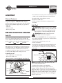
Owner’s Manual
Manuel de l'utilisateur
Manual del Propietario
1000
Starting
Watts
Questions? Help is just a moment away!
Vous avez des questions? Vous n'avez pas besoin d'aller loin pour trouver de l'aide!
Preguntas? La ayuda es justa un momento lejos!
Call: Generator Helpline - 1-800-743-4115 M-F 8-5 CT
Appelez: Ligne d'assistance de Générateur - 1-800-743-4115 M-F 8-5 CT
Llamada: Generador Helpline - 1-800-743-4115 M-F 8-5 CT
BRIGGS & STRATTON POWER PRODUCTS GROUP, LLC
JEFFERSON, WISCONSIN, U.S.A.
Model 01532-2
Manual No. 192115GS
Revision 0 (01/07/2003)
900W Generator
TABLE OF CONTENTS
SAFETY RULES
Safety Rules. . . . . . . . . . . . . . . . . . . . . . . . . . . . . . . . . . 2-4
Know Your Generator . . . . . . . . . . . . . . . . . . . . . . . . . . . 5
Assembly . . . . . . . . . . . . . . . . . . . . . . . . . . . . . . . . . . . . . 6
Operation . . . . . . . . . . . . . . . . . . . . . . . . . . . . . . . . . . 7-10
Maintenance . . . . . . . . . . . . . . . . . . . . . . . . . . . . . . . 11-13
Storage . . . . . . . . . . . . . . . . . . . . . . . . . . . . . . . . . . . 13-14
Notes . . . . . . . . . . . . . . . . . . . . . . . . . . . . . . . . . . . . . . . 15
Troubleshooting . . . . . . . . . . . . . . . . . . . . . . . . . . . . . . . 16
Schematic/Wiring Diagram . . . . . . . . . . . . . . . . . . . . . . . 17
Replacement Parts. . . . . . . . . . . . . . . . . . . . . . . . . . . 18-25
Emmision Control Warranty . . . . . . . . . . . . . . . . . . . . . 26
Warranty . . . . . . . . . . . . . . . . . . . . . . . . . . . . . . . . . . . . 27
This is the safety alert symbol. It is used to
alert you to potential personal injury
hazards. Obey all safety messages that follow
this symbol to avoid possible injury or death.
The safety alert symbol ( ) is used with a signal word
(DANGER, CAUTION, WARNING), a pictorial and/or a
safety message to alert you to hazards. DANGER
indicates a hazard which, if not avoided, will result in death
or serious injury. WARNING indicates a hazard which, if
not avoided, could result in death or serious injury.
CAUTION indicates a hazard which, if not avoided, might
result in minor or moderate injury. CAUTION, when
used without the alert symbol, indicates a situation that
could result in equipment damage. Follow safety messages
to avoid or reduce the risk of injury or death.
In the State of California a spark arrester is required by law
(Section 4442 of the California Public Resources Code).
Other states may have similar laws. Federal laws apply on
federal lands. If you equip the muffler with a spark arrester,
it must be maintained in effective working order.
EQUIPMENT
DESCRIPTION
Read this manual carefully and become familiar
with your generator. Know its applications, its
limitations and any hazards involved.
The generators are an engine–driven, revolving field,
alternating current (AC) generator. It was designed to supply
electrical power for operating compatible electrical lighting,
appliances, tools and motor loads. The generator’s revolving
field is driven at about 3,600 rpm by a single-cylinder engine.
WARNING
The engine exhaust from this product contains
chemicals known to the State of California to cause
cancer, birth defects, or other reproductive harm.
CAUTION! DO NOT exceed the generator’s
wattage/amperage capacity. See “Don’t Overload the
Generator” on page 10.
Every effort has been made to ensure that information in this
manual is accurate and current. However, we reserve the
right to change, alter or otherwise improve the product and
this document at any time without prior notice.
The Emission Control System for this generator is warranted
for standards set by the Environmental Protection Agency.
2
900W Generator
DANGER
DANGER
Storage batteries give off explosive hydrogen gas
during recharging.
Hydrogen gas stays around battery for a long
time after battery has been charged.
Slightest spark will ignite hydrogen and cause
explosion.
You can be blinded or severely injured.
Battery electrolyte fluid contains acid and is
extremely caustic.
Contact with battery fluid will cause severe
chemical burns.
Running generator gives off carbon monoxide,
an odorless, colorless, poison gas.
Breathing carbon monoxide will cause nausea,
fainting or death.
• Operate generator ONLY outdoors.
• Keep at least 2 feet of clearance on all sides of generator for
adequate ventilation.
• DO NOT operate generator inside any building or enclosure,
including the generator compartment of a recreational vehicle (RV).
DANGER
• DO NOT allow any open flame, spark, heat, or lit cigarette
during and for several minutes after charging a battery.
• Wear protective goggles, rubber apron, and rubber gloves.
Failure to properly ground generator can result
in electrocution, especially if the generator is
equipped with a wheel kit.
• National Electric Code requires generator to be properly
grounded to an approved earth ground. Call an electrician for
local grounding requirements.
WARNING
Fuel and its vapors are extremely flammable and
explosive.
Fire or explosion can cause severe burns or
death.
DANGER
Generator produces powerful voltage.
Failure to isolate generator from power utility
can result in death or injury to electric utility
workers due to backfeed of electrical energy.
WHEN ADDING FUEL
• Turn generator OFF and let it cool at least 2 minutes before
removing gas cap. Loosen cap slowly to relieve pressure in tank.
• Fill fuel tank outdoors.
• DO NOT overfill tank. Allow space for fuel expansion.
• Keep fuel away from sparks, open flames, pilot lights, heat, and
other ignition sources.
• DO NOT light a cigarette or smoke.
WHEN OPERATING EQUIPMENT
• When using generator for backup power, notify utility
company. Use approved transfer equipment to isolate
generator from electric utility.
• Use a ground circuit fault interrupter (GFCI) in any damp or
highly conductive area, such as metal decking or steel work.
• DO NOT touch bare wires or receptacles.
• DO NOT use generator with electrical cords which are worn,
frayed, bare or otherwise damaged.
• DO NOT operate generator in the rain.
• DO NOT handle generator or electrical cords while standing
in water, while barefoot, or while hands or feet are wet.
• DO NOT allow unqualified persons or children to operate or
service generator.
• DO NOT tip engine or equipment at angle which causes fuel
to spill.
• This generator is not for use in mobile equipment or marine
applications.
WHEN TRANSPORTING OR REPAIRING EQUIPMENT
• Transport/repair with fuel tank EMPTY or with fuel shutoff
valve OFF.
• Disconnect spark plug wire.
WHEN STORING FUEL OR EQUIPMENT WITH FUEL
IN TANK
WARNING
• This generator does not meet U. S. Coast Guard Regulation
33CFR-183 and should not be used on marine applications.
• Failure to use the appropriate U. S. Coast Guard approved
generator could result in bodily injury and/or property damage.
• Store away from furnaces, stoves, water heaters, clothes
dryers or other appliances that have pilot light or other
ignition source because they can ignite fuel vapors.
3
900W Generator
CAUTION
WARNING
Exceeding generators wattage/amperage capacity can
damage generator and/or electrical devices connected
to it.
Unintentional sparking can result in fire or
electric shock.
• See “Don’t Overload Your Generator” on page 10.
• Start generator and let engine stabilize before connecting
electrical loads.
• Connect electrical loads in OFF position, then turn ON for
operation.
• Turn electrical loads OFF and disconnect from generator
before stopping generator.
WHEN ADJUSTING OR MAKING REPAIRS TO YOUR
GENERATOR
• Disconnect the spark plug wire from the spark plug and place
the wire where it cannot contact spark plug.
WARNING
CAUTION
Running engines produce heat. Temperature of
muffler and nearby areas can reach or exceed
150°F (65°C).
Severe burns can occur on contact.
Improper treatment of generator can damage it and
shorten its life.
• Use generator only for intended uses.
• If you have questions about intended use, ask dealer or
contact your nearest authorized service center.
• Operate generator only on level surfaces.
• DO NOT expose generator to excessive moisture, dust, dirt,
or corrosive vapors.
• DO NOT insert any objects through cooling slots.
• If connected devices overheat, turn them off and disconnect
them from generator.
• Shut off generator if:
-electrical output is lost;
-equipment sparks, smokes, or emits flames;
-unit vibrates excessively.
• DO NOT touch hot surfaces.
• Allow equipment to cool before touching.
CAUTION
Excessively high operating speeds increase risk of injury
and damage to generator.
Excessively low speeds impose a heavy load.
• DO NOT tamper with governed speed. Generator supplies
correct rated frequency and voltage when running at governed
speed.
• DO NOT modify generator in any way.
4
900W Generator
KNOW YOUR GENERATOR
Read this owner’s manual and safety rules before operating your generator.
Compare the illustrations with your generator to familiarize yourself with the locations of various controls and
adjustments. Save this manual for future reference.
Spark Plug (inside
cover)
Fuel Tank
Engine ON/OFF Switch
12 Volt DC, 8.3 Amp
Accessory Jack
Choke Lever
Circuit Breaker (AC)
Air Cleaner
120 Volt AC, 7.5 Amp
Receptacle
Fuel Shut-Off Valve
Oil Fill/Drain
(inside cover)
Recoil Starter
Data Tag
Grounding Lug
Engine ON/OFF Switch — Used to stop a running
engine.
12 Volt DC, 8.3 Amp Accessory Jack — May be used
to power 12 Volt DC electrical devices or recharge 12 Volt
DC batteries.
Fuel Shut-Off Valve — Use this valve to turn the fuel
supply on and off.
120 Volt AC, 7.5 Amp Receptacles — May be used to
supply electrical power for the operation of 120 Volt AC,
single phase, 60 Hz electrical lighting, appliance, tool and
motor loads.
Fuel Tank — Capacity of 1.2 U.S. gallons (4.5 liters) of
fuel.
Air Cleaner — Uses a foam element to limit the amount
of dirt and dust that enters the engine.
Grounding Lug — Use this connection to properly
ground the generator. See ”Grounding the Generator” on
page 7.
Choke Lever — Used to manually provide proper starting
mixture when engine is cold.
Oil Fill/Drain — Access to oil fill dipstick and engine oil
drain plug.
Circuit Breaker (AC) — Receptacles are provided with a
push-to-reset circuit breaker to protect the generator
against electrical overload.
Recoil Starter — Used for starting the engine.
Spark Plug — Access to engine spark plug.
Data Tag — Provides model, revision and serial number
of generator. Please have these readily available if calling for
assistance.
5
900W Generator
ASSEMBLY
• If the oil level is not at the point of overflowing from the
oil filler neck, slowly fill engine with recommended oil.
Carton Contents
• Reinstall oil filler cap and tighten securely.
• Replace the oil fill cover.
Check all contents. If any parts are missing or damaged, call
the generator helpline at 1-800-743-4115. If calling for
assistance, please have the model, revision, and serial number
from the data tag available. Shipped with your generator is:
• Main unit
• Oil bottle
• Owner’s manual
• Battery charge cables
• Check the engine oil level before starting each time
thereafter.
Add Fuel
WARNING! NEVER fill fuel tank indoors. NEVER
fill fuel tank when engine is running or hot. Allow unit
to cool for two minutes before refueling. DO NOT
light a cigarette or smoke when filling the fuel tank.
BEFORE STARTING ENGINE
WARNING! DO NOT overfill the fuel tank.
Always allow room for fuel expansion.
Add Oil
• Use clean fresh UNLEADED fuel with a pump rating of
86 or higher. DO NOT use premium or leaded fuel. DO
NOT mix oil with fuel.
NOTE: When adding oil to the engine crankcase in the
future, use only high quality detergent oil rated with API
service classification SG, SF/CC, CD. Select the oil’s viscosity
grade according to your expected operating temperature:
colder
32°F
warmer
• Clean area around fuel fill cap, remove cap.
• Check the fuel level.
• If fuel level is low, slowly add recommended fuel to fuel
tank, up to the shoulder of the fuel strainer (Figure 2).
Be careful not to overfill (there should be no fuel in the
filler neck).
SAE 10W30
SAE 30
SAE 10W-30 is recommended for general all temperature
use. Multi-viscosity oils (10W30, etc.) improve starting in
cold weather, but these oils will result in increased oil
consumption. Check your engine oil level more frequently
to avoid possible damage from running low on oil.
Figure 2 — Fuel Level
To Add Engine Oil:
• Place the generator on a level surface.
Fill to This Level
• Remove the oil fill cover.
• Remove oil filler cap and wipe dipstick clean (Figure 1).
Figure 1 — Adding Engine Oil
NOTE: Occasionally clear the fuel strainer of any dirt,
rust, or other particulate matter.
• Install fuel cap and wipe up any spilled fuel.
Occasionally you may hear a light “spark knock” or
“pinging” (metallic rapping noise) while operating under
heavy loads. This is no cause for concern. If spark knock or
pinging occurs at a steady engine speed under normal load,
change brands of fuel or obtain a higher octane rated fuel.
If pinging or spark knock persists, see your local Briggs &
Stratton repair center.
Oil Filler Neck
6
900W Generator
GROUNDING THE
GENERATOR
• Be sure the spark plug wire is attached to the spark plug.
• Turn the fuel valve to the “Open” position (fully
clockwise) (Figure 4).
Figure 4 — Fuel Valve in Open Position
The National Electrical Code requires that the frame and
external electrically conductive parts of this generator be
properly connected to an approved earth ground. Local
electrical codes may also require proper grounding of the
unit. For that purpose, a GROUNDING WING NUT is
provided on the generator housing (Figure 3).
Figure 3 — Grounding Wing Nut
• Slide the choke lever to the “Choke” position (all the
way to the right) (Figure 5).
Figure 5 — Choke Lever
Grounding Wing Nut
Generally, connecting a No. 12 AWG (American Wire
Gauge) stranded copper wire to the grounding wing nut
and to an earth-driven copper or brass grounding rod
(electrode) provides adequate protection against electrical
shock. Be careful to keep the grounding wire attached after
connecting the stranded copper wire. However, local codes
may vary widely. Consult with a local electrician for
grounding requirements in your area.
Properly grounding the generator helps prevent electrical
shock if a ground fault condition exists in the generator or
in connected electrical devices. Proper grounding also helps
dissipate static electricity, which often builds up in
ungrounded devices.
• Place the engine switch in the “On” position (Figure 6).
Figure 6 — Engine Switch in On Position
OPERATING THE
GENERATOR
CAUTION! NEVER start or stop the engine with
electrical loads connected to the unit and with the
connected devices turned ON.
• Grasp starter grip and slowly pull the rope until you feel
some resistance, then pull the cord out with a rapid full
arm stroke. Let rope return slowly. DO NOT let rope
“snap back” against the unit.
Starting the Engine
Disconnect all electrical loads from the generator. Use the
following start instructions:
7
900W Generator
Oil Alert System
NOTE: If engine starts after 3 pulls, but fails to run for
more than 10 seconds, check for proper oil level in
crankcase. This unit is equipped with a Oil Alert System
(see page 8).
The Oil Alert System is designed to prevent engine damage
caused by an insufficient amount of oil in the crankcase.
Before the oil level in the crankcase can fall below a safe
limit, the Oil Alert System will automatically shut down the
engine (the engine switch will remain in the “On” position).
• Slide the choke lever left to the “Run” position as the
engine warms up.
NOTE: Under no load conditions, the engine speed may
vary slightly faster or slower until engine temperatures
stabilize.
If the Oil Alert System shuts down the engine, add engine
oil.
Charging a Battery
CAUTION! Breathing Hazard! NEVER run
engine in enclosed poorly ventilated areas. Engine
exhaust contains carbon monoxide, an odorless and
deadly gas.
WARNING! Storage batteries emit explosive gas
while charging that remains around a battery for a
long time after it has been charged. The slightest
spark can ignite the gas, causing an explosion that
can shatter the battery and cause blindness or
other injury.
Connecting Electrical Loads
• Let engine stabilize and warm up for a few minutes after
starting.
WARNING! DO NOT permit smoking, open
flame, sparks or any other source of heat around a
battery. DO NOT use a lighter or other flame for
checking battery fluid levels. Wear protective
goggles, rubber apron and rubber gloves when
working around a battery. Battery electrolyte fluid is
an extremely caustic sulfuric acid solution that can
cause severe burns. DO NOT permit fluid contact
with eyes, skin, clothing, etc. If spill occurs, flush
area with clear water immediately.
• DO NOT connect 240 Volt loads to 120 Volt receptacles.
• DO NOT connect 3–phase loads to the generator.
• DO NOT connect 50 Hz loads to the generator.
• Plug in and turn on the desired 120 Volt AC, single
phase, 60 Hertz electrical loads.
• DO NOT OVERLOAD THE GENERATOR. Add up
the rated watts (or amps) of all loads to be connected at
one time. This total should not be greater than the rated
wattage/amperage capacity of the generator. See “Don’t
Overload the Generator” on page 10.
Your generator has the capability of recharging a discharged
12 Volt automotive or utility style storage battery. DO
NOT use the unit to charge any 6 Volt batteries. DO NOT
use the unit to crank an engine having a discharged battery.
Stopping the Engine
• Unplug all electrical loads from the unit. NEVER start or
stop engine with electrical devices plugged in and turned
on.
To recharge 12 Volt batteries, proceed as follows:
• If necessary, clean battery posts or terminals.
• Let engine run at no–load for two minutes to stabilize
the internal temperatures.
• Move engine switch to the “Off” position.
• Check fluid level in all battery cells. If necessary, add
ONLY distilled water to cover separators in battery
cells. DO NOT use tap water.
• Turn the fuel valve to the “Close” position (fully
counterclockwise).
• If the battery is equipped with vent caps, make sure they
are installed and are tight.
NOTE: In an emergency, stop the engine by moving the
engine switch to the “Off” position.
• Connect battery charge cable connector plug to the
12 Volt DC panel receptacle.
• Connect battery charge cable clamp with red handle to
battery post or terminal indicated by Positive, POS or
(+) (Figure 7).
8
900W Generator
CAUTION! Although each receptacle is rated
Figure 7 — Battery Connections
for 120 Volts at 15 Amps (1,440 watts or 1.44 kW),
the generator is rated for a total of 1,000 watts.
Powering loads that exceed the wattage capacity of
the generator can damage it or cause serious
injuries. The total of loads powered through these
receptacles should not exceed 7.5 Amps.
To 12 Volt DC Panel
Receptacle
Red Lead
12 Volt DC Accessory Jack
Positive
This receptacle allows you to recharge a 12 Volt
automotive or utility style storage battery with the battery
charge cable provided. Camping-style air pumps, lanterns,
fans, or other 12 Volt devices having a cigarette lighter-type
plug may also be powered by this outlet (Figure 9).
Negative
Figure 9 — 12 Volt DC Accessory Jack
• Connect battery charge cable clamp with black handle
to battery post or terminal indicated by Negative,
NEG, or (–) (Figure 7).
• Start generator. Let the engine run while battery
recharges.
• When battery has charged, shut down engine (see
“Stopping The Engine”)
NOTE: Use an automotive hydrometer to test battery
state of charge and condition. Follow the hydrometer
manufacturer’s instructions carefully. Generally, a battery is
considered to be at 100% state of charge when specific
gravity of its fluid (as measured by hydrometer) is 1.260 or
higher.
CONNECTOR PLUGS
This receptacle can not recharge 6 Volt batteries and can
not be used to crank an engine having a discharged battery.
See “Charging a Battery” (page 8) before attempting to
recharge a battery.
120 Volt AC, 15 Amp Receptacle
EXTENSION CORDS
Each outlet socket is protected against overload by a
7.5 Amp push-to-reset circuit breaker. Use each receptacle
to operate 120 Volt AC, single phase, 60 Hz electrical loads
requiring up to 1,000 watts (1.0 kW) of power (Figure 8).
Use only high quality, well-insulated, extension cords with
the generator’s 120 Volt electrical receptacles.
Check the ratings of all extension cords before you use
them. Such cords should be rated for 125 Volt AC loads at
15 Amps (or greater) for most electrical devices. Some
devices, however, may not require this type of extension
cord. Check the owner’s manuals of those devices for their
recommendations.
Figure 8 — 120 Volt AC, 15 Amp Duplex Receptacle
Keep extension cords as short as possible, preferably less
than 15 feet long, to prevent voltage drop and possible
overheating of wires.
9
900W Generator
DON'T OVERLOAD YOUR
GENERATOR
4. Plug in and turn on the next load.
5. Again, permit the generator to stabilize.
6. Repeat steps 4 and 5 for each additional load.
NEVER add more loads than the generator capacity. Take
special care to consider surge loads in generator capacity,
as described above.
Capacity
You must make sure your generator can supply enough
rated (running) and surge (starting) watts for the items you
will power at the same time. Follow these simple steps:
1. Select the items you will power at the same time.
2. Total the rated (running) watts of these items. This is
the amount of power your generator must produce to
keep your items running. See Figure 10.
3. Estimate how many surge (starting) watts you will
need. Surge wattage is the short burst of power
needed to start electric motor-driven tools or
appliances such as a circular saw or refrigerator.
Because not all motors start at the same time, total
surge watts can be estimated by adding only the
item(s) with the highest additional surge watts to the
total rated watts from step 2.
Figure 10 - Wattage Reference Chart
Tool or Appliance
Essentials
Light Bulb - 75 watt
Deep Freezer
Sump Pump
Refrigerator/Freezer - 18 Cu. Ft.
Water Well Pump - 1/3 HP
Heating/Cooling
Window AC - 10,000 BTU
Window Fan
Furnace Fan Blower - 1/2 HP
Kitchen
Microwave Oven - 1000 Watt
Coffee Maker
Electric Stove - Single Element
Hot Plate
Family Room
DVD/CD Player
VCR
Stereo Receiver
Color Television - 27”
Personal Computer w/17” monitor
Other
Security System
AM/FM Clock Radio
Garage Door Opener - 1/2 HP
Electric Water Heater - 40 Gallon
DIY/Job Site
Quartz Halogen Work Light
Airless Sprayer - 1/3 HP
Reciprocating Saw
Electric Drill - 1/2 HP
Circular Saw - 7 1/4”
Miter Saw - 10”
Table Planer - 6”
Table Saw/Radial Arm Saw - 10”
Air Compressor - 1-1/2 HP
Example:
Tool or Appliance
Window Air
Conditioner
Refrigerator
Deep Freezer
Television
Light (75 Watts)
Rated (Running)
Watts
1200
Additional Surge
(Starting) Watts
1800
800
500
500
75
3075 Total
Running Watts
1600
500
1800 Highest
Surge Watts
Total Rated (Running) Watts
= 3075
Highest Additional Surge Watts
= 1800
Total Generator Output Required = 4875
Power Management
To prolong the life of your generator and attached devices,
it is important to take care when adding electrical loads to
your generator. There should be nothing connected to the
generator outlets before starting it's engine. The correct
and safe way to manage generator power is to sequentially
add loads as follows:
1. With nothing connected to the generator, start the
engine as described in this manual.
2. Plug in and turn on the first load, preferably the largest
load you have.
3. Permit the generator output to stabilize (engine runs
smoothly and attached device operates properly.
Rated*
(Running)
Watts
Additional
Surge
(Starting)
Watts
75
500
800
800
1000
500
1200
1600
2000
1200
300
800
1800
600
1300
1000
1500
1500
2500
-
100
100
450
500
800
-
180
300
480
4000
520
-
1000
600
960
1000
1500
1800
1800
2000
2500
1200
960
1000
1500
1800
1800
2000
2500
*Wattages listed are approximate only. Check tool or
appliance for actual wattage.
10
900W Generator
PRODUCT
SPECIFICATIONS
GENERAL MAINTENANCE
RECOMMENDATIONS
The generator warranty does not cover items that have
been subjected to operator abuse or negligence. To receive
full value from the warranty, operator must maintain
generator as instructed in this manual.
Generator Specifications
Rated Surge Watts . . . . . . . . . . . . . . . 1,000 Watts
Rated Running Watts . . . . . . . . . . . . . 900 Watts
Rated Maximum Current
At 120 Volts AC . . . . . . . . . . . . . .7.5 Amps
At 12 Volts DC . . . . . . . . . . . . . . .8.3 Amps
Phase . . . . . . . . . . . . . . . . . . . . . . . .Single Phase
Rated Frequency . . . . . . . . . . . . . . . .60 Hertz
Packaged Weight . . . . . . . . . . . . . . . .61 lbs.
Some adjustments will need to be made periodically to
properly maintain your generator.
All adjustments in this section should be made at least
once each season. Follow the requirements in the
“Maintenance Schedule” chart shown below in Figure 11.
NOTE: Once a year you should clean or replace the spark
plug and replace the air filter. A new spark plug and clean
air filter assure proper fuel-air mixture and help your
engine run better and last longer.
Engine Specifications
Model . . . . . . . . . . . . . . . . . . . . . . . . Mitsubishi GM82
Rated Horsepower . . . . . . . . . . . . . . 2.4 at 4000 rpm
Displacement . . . . . . . . . . . . . . . . . . . 80cc
Spark Plug Type: . . . . . . . . . . . . . . . . . NGK BP6HS or
equivalent
Set Gap To: . . . . . . . . . . . . . . . . . . . . . 0.030inch (0.75mm)
Fuel Capacity . . . . . . . . . . . . . . . . . . . 1.2 U.S. gallons (4.5 l)
GENERATOR
MAINTENANCE
Generator maintenance consists of keeping the unit clean
and dry. Operate and store the unit in a clean dry
environment where it will not be exposed to excessive
dust, dirt, moisture or any corrosive vapors. Cooling air
slots in the generator must not become clogged with snow,
leaves or any other foreign material.
Figure 11 – Maintenance Schedule
Item
Operation
Each use
First Month or
25 hours
Engine oil
Every 3 months
or 50 hours
Every 6 months
or 100 hours
Check level
X
Change
X
X
Air cleaner
Check
X
Clean
X (1)
Spark arrester
Check – Clean
X (2,3)
Spark plug
Check – Clean
X
Valve clearance
Check – Adjust
X (3)
Fuel tank strainer Clean
X (3)
Fuel line
Check (Replace if
Every 3 years (3)
necessary)
1 Clean more often under dirty or dusty conditions. Replace cleaner parts if very dirty.
2 Check every 10 hours or 3 months.
3 These items should be serviced by an authorized dealer, unless the owner has the proper tools and is mechanically
proficient.
11
900W Generator
Check the cleanliness of the generator frequently and clean
when dust, dirt, oil, moisture or other foreign substances
are visible on its exterior surface.
• Remove the oil fill cover and clean area around oil drain
plug (Figure 12).
Figure 12 — Oil Drain Plug
NOTE: DO NOT use a garden hose to clean generator.
Water can enter engine fuel system and cause problems. In
addition, if water enters generator through cooling air
slots, some of the water will be retained in voids and
cracks of the rotor and stator winding insulation. Water
and dirt buildup on the generator internal windings will
eventually decrease the insulation resistance of these
windings.
To Clean the Generator
Oil Drain Plug
• Use a damp cloth to wipe exterior surfaces clean.
• Remove oil drain plug, sealing washer, and oil filler cap.
Drain oil completely into a suitable container.
• Soft, bristle brush may be used to loosen caked on dirt
or oil.
• Install oil drain plug and sealing washer. Tighten securely.
CAUTION! NEVER insert any object or tool
• Refill with recommended oil and check the level. See
page 6 for oil recommendations.
through the air cooling slots, even if the engine is
not running.
• Wipe up any spilled oil.
• A vacuum cleaner may be used to pick up loose dirt and
debris.
CAUTION! Avoid prolonged or repeated skin
contact with used motor oil. Used motor oil has
been shown to cause skin cancer in certain
laboratory animals. Thoroughly wash exposed areas
with soap and water. KEEP OUT OF REACH OF
CHILDREN.
DON'T POLLUTE. CONSERVE RESOURCES.
RETURN USED OIL TO COLLECTION CENTERS.
• Low pressure air (not to exceed 25 psi) may be used to
blow away dirt. Inspect cooling air slots and opening on
generator. These openings must be kept clean and
unobstructed.
WARNING! When working on the generator
always disconnect spark plug wire from spark plug
and keep it away from spark plug.
• Replace oil fill cover.
Clean/Replace Spark Plug
ENGINE MAINTENANCE
Check and clean the spark plug every 50 hours of
operation or every three months, whichever comes first.
This will help your engine to start easier and run better.
Checking Oil Level
Oil level should be checked prior to each use or at least
every 5 hours of operation. Keep oil level maintained.
• Remove spark plug access cover. Remove spark plug cap.
Changing Engine Oil
• Remove and inspect the spark plug.
Change the oil after the first month of operation, then
every 25 hours. If you are using your generator under
extremely dirty or dusty conditions, or in extremely hot
weather, change the oil more often.
• Replace the spark plug if electrodes are pitted or burned
or the porcelain is cracked. Use recommended plug for
replacement.
• Clean the area around the spark plug.
• Check electrode gap with wire feeler gauge and set spark
plug gap between 0.028 and 0.031 inch (0.7 to 0.8 mm) if
necessary (Figure 13).
Change the oil while the engine is still warm from running,
as follows:
12
900W Generator
Figure 13 — Service Spark Plug
Figure 14 – Service Spark Arrester Screen
Muffler Tail Pipe
Spark Arrester
Screen
• Reinstall spark plug.
Spark Arrester
Attachment Screw
Service Air Cleaner
Your engine will not run properly and may be damaged if
you run it using a dirty air filter element.
Check the air filter every use and clean or replace the
paper air filter element every 50 hours of operation or
every three months, whichever comes first. Clean or
replace more often if operating under dusty or dirty
conditions.
• Use a brass or stiff-bristle brush to remove carbon
deposits from the spark arrester surface.
• Inspect the spark arrester for breaks or tears and
replace it if necessary.
To clean or replace air filter element:
• Loosen the air cleaner cover screws, remove the air
cleaner cover, and remove the element (see item
number 4, exploded view on page 22.
NOTE: If you need to order a new spark arrester, please
call 1-800-743-4115.
• Install the clean screen in the reverse order of removal.
NOTE: If you use your generator on any forest-covered,
brush-covered or grass-covered unimproved land, it must
have a spark arrester installed. The spark arrester must be
maintained in good condition by the owner/operator.
• Wipe clean the inside of the filter housing and cover
thoroughly.
• Wash the element in a solution of household detergent
and warm water, then rinse thoroughly. Or wash in
nonflammable or high flash point solvent. Allow the
element to dry thoroughly.
STORAGE INSTRUCTIONS
• Soak the element in clean engine oil and squeeze out the
excess oil. DO NOT twist. The engine will smoke during
initial start-up if too much oil is left in the element.
Transporting and Storage
When transporting the generator, turn the engine switch
to “Off” and the fuel valve to “Close”. Keep the generator
level to prevent fuel spillage.
NOTE: If you need to order a new air filter element,
please call 1-800-743-4115.
WARNING! Contact with a hot engine or
exhaust system can cause serious burns or fires. Let
the engine cool before transporting or storing the
generator.
Take care to not drop or strike the generator when
transporting. DO NOT place heavy objects on the
generator.
• Reinstall the air cleaner element and the cover. Hand
tighten the air cleaner cover screws.
Clean Spark Arrester Screen
The engine muffler is equipped with a removable spark
arrester screen. Inspect and clean the screen every
10 hours of operation or every three months, as shown in
Figure 14:
The generator should be started at least once every seven
days and allowed to run at least 30 minutes. If this cannot
be done and you must store the unit for more than 30 days,
use the following guidelines to prepare it for storage.
• Loosen the screw on the muffler tail pipe and remove
the spark arrester screen.
13
900W Generator
Long Term Storage Instructions
• Retighten drain screw before refueling.
Change Oil
While engine is still warm, change oil as described on
page 12. Refill with recommended grade.
WARNING! NEVER store engine with fuel in
tank indoors or in enclosed, poorly ventilated areas
where fumes may reach an open flame, spark or
pilot light as on a furnace, water heater, clothes
dryer or other gas appliance.
Be sure the storage area is free from excessive
humidity and dust.
Oil Cylinder Bore
• Remove spark plug and pour about one tablespoon of
clean engine oil into the cylinder.
CAUTION! Avoid spray from spark plug hole
One Month to One Year
Drain the carburetor float bowl (see following section) and
fuel tank into a suitable container. After removal from
storage, fill with fresh fuel before starting.
when cranking engine slowly.
• Cover spark plug hole with rag. Crank slowly several
times to distribute oil.
• Install spark plug. DO NOT connect spark plug wire.
More than One Year
It is important to prevent gum deposits from forming in
essential fuel system parts such as the carburetor, fuel filter,
fuel hose or tank during storage. Also, experience indicates
that alcohol-blended fuels (called gasohol, ethanol or
methanol) can attract moisture, which leads to separation
and formation of acids during storage. Acidic gas can
damage the fuel system of an engine while in storage.
• Slowly pull the starter grip until resistance is felt. At this
point, the piston is coming up on its compression stroke
and both the intake and exhaust valves are closed.
Storing the engine in this position will help to protect it
from internal corrosion.
Generator
• Clean the generator as outlined on page 12 (“To Clean
the Generator”).
To avoid engine problems, the fuel system should be
emptied before storage of 30 days or longer. Follow these
instructions:
• Check that cooling air slots and openings on generator
are open and unobstructed.
Protect Fuel System
Other Storage Tips
WARNING! Drain fuel into approved container
• DO NOT store fuel from one season to another.
outdoors, away from open flame. Be sure engine is
cool. DO NOT smoke.
• Replace the fuel can if it starts to rust. Rust and/or dirt
in fuel will cause problems.
• Drain carburetor float bowl and fuel tank into a suitable
container by loosening the drain screw (Figure 15).
• If possible, store your unit indoors. BE SURE TO
EMPTY THE FUEL TANK.
Figure 15 – Drain Fuel From Carburetor
• Cover your unit with a suitable protective cover that
does not retain moisture.
Carburetor Fuel
Drain Screw
IMPORTANT: NEVER cover your generator while engine
and exhaust area are warm.
• Store generator in clean, dry area.
Drain Screw
Access Hole
14
900W Generator
NOTES
15
900W Generator
TROUBLESHOOTING
Problem
No AC or DC output
is available but
engine is running.
Generator runs good
at no-load but
“bogs down" when
loads are
connected.
Engine will not start;
or starts and runs
rough.
Cause
Correction
1.
2.
One of the circuit breakers is open.
Fault in generator.
1.
2.
3.
4.
Poor connection or defective cord set.
Connected device is bad.
3.
4.
1.
2.
Short circuit in a connected load.
Engine speed is too slow.
1.
2.
3.
Generator is overloaded.
3.
4.
Shorted generator circuit.
4.
1.
2.
Engine switch set to “Off”.
Fuel valve in the “Closed” position.
1.
2.
3.
4.
5.
Dirty air cleaner.
Out of gasoline.
Stale gasoline.
3.
4.
5.
6.
Spark plug wire not connected to spark
plug.
Bad spark plug.
Water in gasoline.
6.
7.
8.
9.
10.
11.
12.
Engine shuts down
when running.
1.
2.
1.
Engine lacks power.
2.
1.
Engine “hunts” or
falters.
2.
Replace spark plug.
Drain gas tank and carburetor; fill
with fresh fuel.
Overchoked or flooded.
9. Wait 5 minutes and re-crank engine.
Excessively rich fuel mixture.
10. Contact Briggs & Stratton service
facility.
Intake valve stuck open or closed.
11. Contact Briggs & Stratton service
facility.
Engine has lost compression.
12. Contact Briggs & Stratton service
facility.
Out of gasoline.
1. Fill fuel tank.
Low oil level.
2. Fill cranckcase to proper level.
Load is too high.
1. See “Don't Overload the Generator”
on page 10.
Dirty air filter.
2. Replace air filter.
Choke is opened to soon.
1. Move choke to halfway position until
engine runs smoothly.
Carburetor is running too rich or too lean. 2. Contact Briggs & Stratton service
facility.
16
7.
8.
Reset circuit breaker.
Contact Briggs & Stratton Power
Products service facility.
Check and repair.
Connect another device that is in
good condition.
Disconnect shorted electrical load.
Contact Briggs & Stratton service
facility.
See “Don't Overload the Generator”
on page 10.
Contact Briggs & Stratton Power
Products service facility.
Set switch to “On”.
Turn fuel valve to the “Open”
position.
Clean or replace air cleaner.
Fill fuel tank.
Drain gas tank and carburetor; fill
with fresh fuel.
Connect wire to spark plug.
900W Generator
WIRING DIAGRAM
17
900W Generator
EXPLODED VIEW AND PARTS LIST – MAIN UNIT
Item
1
2
3
4
5
6
7
8
9
10
11
12
13
14
15
Part #
NSP
187378GS
187411GS
187379GS
187430GS
187409GS
187381GS
187399GS
187382SGS
187388GS
187389GS
187405GS
187384GS
187407GS
187403GS
Qty Description
1 ENG, MITSUB, 2.4HP
1 ROTOR
1 BRG
1 STATOR
1 LEAD, GREEN
1 BUSHING, LEAD WIRE, G790B
1 RBC, 1K
3 SCREW, SELF TAP, M6-12
1 FAN, COOLING
1 BOLT, RTR
3 BOLT, STATOR
1 INSLTN, HEAT SEALED, #1
1 MFFLR, SEALED
1 INSLTN, HEAT SEALED, #2
1 DUCT, AIR
Item
16
17
18
19
20
21
22
23
24
25
26
27
28
29
18
Part #
187392GS
187383GS
187390GS
187385GS
187427GS
187424GS
187423GS
187419GS
187420GS
187401GS
187415GS
187413GS
187434GS
187431GS
Qty Description
2 PHMS, M6-1.0, W/L/FW
1 BASE, GEN
4 BOLT, FLNG, M6-1.0 X 10
4 MNT, VIBR
4 HHCS, FLNG, M8-1.25 X 12
1 NUT, WING, M5 X 0.8
1 NUT, M5 X 0.8
2 WSHR, LOCK
2 WSHR, FLAT
2 NUT, M8-1.25, FLANGE
1 PHMS, M5-0.8 X 20
2 CNNCTR
4 HHCS, FLNG
1 STND, ENG
900W Generator
EXPLODED VIEW AND PARTS LIST – MAIN UNIT
Item
1
2
3
4
5
6
7
8
10
11
12
13
14
15
16
17
18
19
20
21
22
23
24
Part #
187436GS
187439GS
187438GS
187769GS
187437GS
187766GS
187756GS
187875GS
187772GS
187757GS
187760GS
187435GS
187775GS
191436GS
187774GS
187761GS
187463GS
187874GS
NSP
187457GS
191528GS
187759GS
187462GS
Qty Description
1 CAP, FUEL
1 PACKING, TANK
1 FLTR, FUEL
3 U-PACKING
1 TANK, FUEL, 4.5L
1 DECAL, CHOKE
4 BOLT, COVER (M5-16)
1 HSG, GEN, MFFLR
1 COVER, SPARK PLUG
5 BOLT, COVER (M6-16)
11 PHMS, M4-12 W/FW
1 CVR, MFFLR, GEN
3 BOLT, MFFLR CVR (M6-16)
1 DECAL CAUTION HOT
4 BOLT, COVER (M6-20)
8 NUT, M4X0.6 W/FW
1 INSLTN, MFFLR
1 HSG, GEN
1 DECAL, EMISSIONS
1 CONDENSER, 300V
1 DECAL, WARNING
2 BOLT, COVER (M5-10)
1 DIODE, BRIDGE
Item
25
26
27
28
29
30
31
32
33
34
35
36
37
38
39
40
41
42
43
44
45
46
19
Part #
187371AGS
192284GS
187773GS
187460GS
187454GS
187873GS
187450GS
187812GS
187456GS
187763GS
187876GS
192283GS
191545GS
187447GS
187448GS
187442GS
187758GS
187443GS
187770GS
187579GS
187440GS
187578GS
Qty Description
1 BOTTLE, OIL
1 DECAL, LWR PANEL
1 COVER, OIL FILL
1 CB, DC
1 CB, 8A, 125V
1 OUTLET, ACCESSORY DC
1 SWITCH, ENG, ON/OFF
1 CPNL
1 RECPTCL, 15A, 125V
1 DECAL, CAUTION OIL
1 CABLE, BATTERY CHARGE
1 DECAL, UNIT
1 DECAL, FUEL SHUTOFF
1 INSLTN, HTSHLD, TANK #1
1 INSLTN, HTSHLD, TANK #2
2 BRKT, TANK, FUEL
1 BRKT, FUEL COCK
1 COCK, FUEL
1 PHMS, M5-10 W/FW
1 CLIP, FUEL HOSE
1 FLTR, FUEL
1 HOSE, FUEL
900W Generator
EXPLODED VIEW AND PARTS LIST – ENGINE
Cylinder Block, Cylinder Head
Item
1
2
3
4
5
6
7
8
9
Item
1
2
3
4
5
6
7
8
9
10
Part #
187404GS
187406GS
187408GS
187410GS
187412GS
187414GS
187416GS
187417GS
187418GS
187421GS
Qty Description
1 ASSY, CYL HEAD
2 TPPT, CYL HEAD
2 VLV, EXH
2 SPRNG, VLV
2 RTNR, VLV SPG
2 ROD, PUSH
1 ASSY, RCKR, ARM
2 NUT, CYL HEAD
2 SCRW, ADJST
1 PLT, CYL HEAD
Item
11
12
13
14
15
16
17
18
19
20
Part #
187380GS
187386GS
187387GS
187391GS
187393GS
187394GS
187395GS
187400GS
187402GS
Part #
187422GS
187423GS
187426GS
187428GS
187429GS
187468GS
187470GS
187472GS
187569GS
Qty Description
1 BLOCK, CYL
1 ASSY, GOV, GEAR
1 SLIDER, GOV
1 SHFT, GOV
2 PLUG, DRAIN
2 SEAL, OIL
1 BRG, BALL
1 WSHR, CYLBLOCK
2 GSKT, CYLBLOCK
Qty Description
1 SEAL, VLV STEM
4 NUT, M5 X 0.8
4 BOLT, FLNG
2 PIN, DWL
1 GSKT, HEAD
1 CVR, VALVE
4 BOLT, VALVE CVR
1 GSKT, VALVE CVR
2 BOLT, STUD
900W Generator
EXPLODED VIEW AND PARTS LIST – ENGINE
Crankcase Cover, Crankshaft/Camshaft
Item
1
2
3
4
5
6
7
8
Part #
187394GS
187473GS
187474GS
187475GS
187477GS
187478GS
187428GS
187479GS
Item
1
2
3
4
6
7
8
21
Part #
187481GS
187484GS
187486GS
187487GS
187488GS
187489GS
187490GS
Qty Description
2 SEAL, OIL
1 CVR, CRANKCASE
1 DIPSTICK, OIL
1 O-RING, DIPSTICK
1 BRG, PTO
6 BOLT, CRANKCASE CVR
2 PIN, DWL
1 GSKT, CRANKCASE CVR
Qty Description
1 ASSY, CRNKSHFT
1 GEAR, CRNKSHFT
2 KEY, WOODRFF
1 GEAR, CRNKSHFT
1 ASSY, CAMSHAFT
1 PIN, CMPR REL
1 RNG, SNP, CMPRSSN
REL
900W Generator
EXPLODED VIEW AND PARTS LIST – ENGINE
Piston/Rod, Magneto/Flywheel, Air Cleaner
Item
1
1
1
2
3
3
3
4
5
5
5
6
22
Part #
187526GS
187527GS
187528GS
187529GS
187530GS
187531GS
187532GS
187533GS
187534GS
187535GS
187537GS
187539GS
Qty Description
1 ROD, CNNCTNG, STD
1 ROD, CNNCTNG, US.25
1 ROD, CNNCTNG, US.50
2 BOLT, CNNCTNG ROD
1 ASSY, PSTN, STD
1 ASSY, PSTN, OS.25
1 ASSY, PSTN, OS.50
1 PIN, PISTON
1 SET, RING, PSTN, STD
1 SET, RING, PSTN, OS.25
1 SET, RING, PSTN, OS.50
2 CLIP, SPRING, PSTN PIN
Item
1
2
3
4
5
6
Part #
187540GS
187541GS
187543GS
187544GS
187545GS
187546GS
Qty Description
1 FLYWHL
1 COIL, IGNITION
1 FAN
1 CLIP, MAGNETO
2 BOLT, MAGNETO
1 NUT
Item
1
2
3
4
5
6
7
8
9
10
Part #
187492GS
187494GS
187496GS
187497GS
187498GS
187500GS
187501GS
187503GS
187504GS
187576GS
Qty Description
1 HSNG, AIR CLNR
1 CVR, AIR CLNR
1 SPRT, AIR CLNR
1 ELEMENT, AIR CLNR
1 BRTHR, AIR CLNR
2 STUD, AIR CLNR
2 SCREW, AIR CLNR CVR
2 NUT, AIR CLNR CVR
1 GSKT, CARB
1 DECAL, CHOKE
900W Generator
EXPLODED VIEW AND PARTS LIST – ENGINE
Carburetor, Control/Linkages
Item
1
2
3
4
5
6
7
8
9
10
11
12
13
14
15
16
17
18
19
20
21
22
23
24
25
26
27
28
29
Item
1
2
3
4
5
6
7
8
9
10
11
12
13
14
15
23
Part #
187469GS
187471GS
187476GS
187480GS
187482GS
187483GS
187485GS
187491GS
187493GS
187495GS
187499GS
187502GS
187509GS
187511GS
187525GS
187536GS
187538GS
187542GS
187502GS
187547GS
187548GS
187549GS
187550GS
187551GS
187552GS
187553GS
187554GS
187556GS
187504GS
Part #
187505GS
187506GS
187507GS
187508GS
187510GS
187512GS
187513GS
187514GS
187515GS
187516GS
187517GS
187518GS
187519GS
187520GS
187570GS
Qty Description
1 CARB, COMPLETE
1 JET, MAIN
1 SHFT, THROTTL
1 VLV, NEEDLE
1 CLIP, CARB
1 PIN, CARB
1 VLV, THRTTL
3 HHCS, CARB
1 VLV, CHOKE
1 GSKT, CARB
1 CHMBR, FLOAT
1 SPRING, CARB
1 HHCS, CARB
1 GSKT, CARB
1 BOLT, CARB
1 FLOAT, CARB
1 NZZL, MAIN, CARB
1 HHCS, CARB
1 SPRING, CARB
1 ADJSTR, CARB
1 LEVER, CHOKE
1 JET, PILOT
1 SPRING, CARB
1 CAP, CARB
2 PACKING, CARB
1 SEAL, CARB
1 SEAL, CARB
1 INSLTR, CARB
2 GSKT, CARB
Qty Description
1 BRKT, SPEED CNTRL
1 SPRING, SPEED CNTRL
1 SCREW, SPEED CNTRL
1 SHFT, GOV
1 RING, SNAP, GOV ROD
1 LEVER, GOV
1 ROD, GOV
1 SPRING, GOV LEVER
1 WSHR, GOV LEVER
1 CVR, TOP
1 CLIP, GOV ROD
1 BOLT, SPEED CNTRL BKT
1 BOLT, TOP CVR
2 NUT, GOV LEVER
1 SPRING, GOV
900W Generator
EXPLODED VIEW AND PARTS LIST – ENGINE
Fan Cover, Recoil Starter, Oil Sensor
Item
1
2
3
4
Part #
187521GS
187522GS
187523GS
187524GS
Qty Description
1 CVR, FAN
1 CVR, FAN
1 CVR, FAN
4 BOLT, FAN CVR
Item
1
2
3
4
5
6
Part #
187557GS
187558GS
187559GS
187560GS
187561GS
187562GS
Qty Description
1 ASSY, RECOIL, STRTR
1 STRTR, RECOIL
1 ROPE, RECOIL
1 HNDL, RECOIL
1 PULLEY, STRTR
3 BOLT, FLNG
Item
1
2
3
4
5
6
7
8
24
Part #
187563GS
187564GS
187565GS
187566GS
187567GS
187470GS
187524GS
187568GS
Qty Description
1 CLAMP, OILSNSR
1 SNSR, OIL
1 UNIT, OILSNSR
1 WIRE, LEAD
1 BAND, OILSNSR
2 BOLT, VALVE CVR
1 BOLT, FAN CVR
1 BOLT, FLNG
900W Generator
EXPLODED VIEW AND PARTS LIST – ENGINE
Lead Wires, Muffler, Gasket Set
Item
1
2
3
4
5
Part #
187571GS
187572GS
187573GS
187574GS
187575GS
Qty Description
1 WIRE, LEAD
1 PLUG, SPARK
1 CAP, PLUG
1 TIEWRAP, LEAD WIRE
1 WIRE, LEAD
Item
1
2
3
4
5
6
7
8
Part #
187449GS
188261GS
187446GS
187455GS
187451GS
187444GS
188263GS
188262GS
Qty Description
3 NUT, FLNG
1 PIPE, TAIL
1 GSKT, MFFLR
2 NUT, CONICAL
1 GSKT, MFFLR
1 MFFLR
1 SCREEN, SPARK
1 SCREW
Item
1
2
3
4
5
6
25
Part #
187461GS
187429GS
187472GS
187479GS
187504GS
187451GS
Qty Description
1 SET, GSKT (Includes items 2-6)
1 GSKT, HEAD
1 GSKT, VALVE CVR
1 GSKT, CRANKCASE CVR
3 GSKT, CARB
1 GSKT, MFFLR
EMISSION CONTROL SYSTEM WARRANTY
Briggs & Stratton Power Products (BSPP), the California Air Resources Board (CARB) and
the United States Environmental Protection Agency (U.S.EPA)
Emission Control System Warranty Statement
(Owner's Defect Warranty Rights and Obligations)
EMISSION CONTROL WARRANTY COVERAGE IS
APPLICABLE TO CERTIFIED ENGINES PURCHASED IN
CALIFORNIA IN 1995 AND THEREAFTER WHICH ARE
USED IN CALIFORNIA, AND TO CERTIFIED MODEL YEAR
1997 AND LATER ENGINES WHICH ARE PURCHASED
AND USED ELSEWHERE IN THE UNITED STATES (AND
AFTER JANUARY 1, 2001 IN CANADA).
California and U.S. EPA Emission Control Warranty
Statement Your Warranty Rights and Obligations
The California Air Resources Board (CARB), U.S.EPA and
Briggs & Stratton Power Products (BSPP) are pleased to
explain the Emission Control System Warranty on your model
year 2000 and later small off-road engine (SORE). In California,
new small off-road engines must be designed, built and
equipped to meet the State's stringent anti-smog standards.
Elsewhere in the United States, new non-road, spark-ignition
engines certified for model year 1997 and later, must meet
similar standards set forth by the U.S.EPA. BSPP must warrant
the emission control system on your engine for the periods of
time listed below, provided there has been no abuse, neglect,
or improper maintenance of your small off-road engine.
Your emission control system may include parts such as the
carburetor or fuel-injection system, the ignition system, and
catalytic converter. Also included may be hoses, belts,
connectors and other emission related assemblies.
Where a warrantable condition exists, BSPP will repair your
small off-road engine at no cost to you including diagnosis,
parts and labor.
BSPP Emission Control Defects Warranty Coverage
The 1995 and later small off-road engines are warranted for
two years. If any emission-related part on your engine is
defective, the part will be repaired or replaced by BSPP.
Owner's Warranty Responsibilities
As the small off-road engine owner, you are responsible for
the performance of the required maintenance listed in this
owner's manual. BSPP recommends that you retain all your
receipts covering maintenance on your small off-road engine,
but BSPP cannot deny warranty solely for the lack of receipts
or for your failure to ensure the performance of all scheduled
maintenance.
As the small off-road engine owner, you should however be
aware that BSPP may deny you warranty coverage if your small
off-road engine or a part has failed due to abuse, neglect,
improper maintenance or unapproved modifications.
You are responsible for presenting your small off-road engine
to an approved BSPP Service Center as soon as a problem
exists. The warranty repairs should be completed in a
reasonable amount of time, not to exceed 30 days.
If you have any questions regarding your warranty rights and
responsibilities, you should contact a BSPP Service
Representative at 1-800-743-4115.
BSPP Emission Control Defects Warranty Provisions
The following are specific provisions relative to your Emission
Control Defects Warranty Coverage.
1. Warranted Parts
Coverage under this warranty extends only to the parts
listed below (the emission control systems parts) to the
extent these parts were present on the engine purchased.
2.
3.
4.
5.
6.
a. Fuel Metering System
Cold start enrichment system
Carburetor and internal parts
Fuel Pump
b. Air Induction System
Air cleaner
Intake manifold
c. Ignition System
Spark plug(s)
Magneto ignition system
d. Catalyst System
Catalytic converter
Exhaust manifold
Air injection system or pulse valve
e. Miscellaneous Items Used in Above Systems
Vacuum, temperature, position, time sensitive valves
and switches
Connectors and assemblies
Length of Coverage
BSPP warrants to the initial owner and each subsequent
owner that the Warranted Parts shall be free from defects in
materials and workmanship which caused the failure of the
Warranted Parts for a period of two years from the date the
engine is delivered to a retail purchaser.
No Charge
Repair or replacement of any Warranted Part will be
performed at no charge to the owner, including diagnostic
labor which leads to the determination that a Warranted
Part is defective, if the diagnostic work is performed at an
approved BSPP Service Center.
Claims and Coverage Exclusions
Warranty claims shall be filed in accordance with the
provisions of the BSPP Warranty Policy. Warranty
coverage shall be excluded for failures of Warranted Parts
which are not original BSPP parts or because of abuse,
neglect or improper maintenance as set forth in the BSPP
Engine Warranty Policy. BSPP is not liable to cover failures
of Warranted Parts caused by the use of add-on, nonoriginal, or modified parts.
Maintenance
Any Warranted Part which is not scheduled for
replacement as required maintenance or which is
scheduled only for regular inspection to the effect of
"repair or replace as necessary" shall be warranted as to
defects for the warranty period. Any Warranted Part
which is scheduled for replacement as required
maintenance shall be warranted as to defects only for the
period of time up to the first scheduled replacement for
that part. Any replacement part that is equivalent in
performance and durability may be used in the
performance of any maintenance or repairs. The owner is
responsible for the performance of all required
maintenance, as defined in this owner's manual.
Consequential Coverage
Coverage hereunder shall extend to the failure of any
engine components caused by the failure of any Warranty
Part still under warranty.
In the USA and Canada, a 24-hour hotline, 1-800-233-3723, has a menu of pre-recorded messages offering you product
maintenance information.
BRIGGS & STRATTON POWER PRODUCTS OWNER WARRANTY POLICY Effective January 1, 2003
LIMITED WARRANTY
“Briggs & Stratton Power Products will repair or replace, free of charge, any part, or parts of the equipment**that are defective
in material or workmanship or both. Transportation charges on parts submitted for repair or replacement under this warranty
must be borne by purchaser. This warranty is effective for the time periods and subject to the conditions provided for in this
policy. For warranty service, find the nearest Authorized service dealer by calling 1-800-743-4115. Warranty service may only be
performed by a Briggs & Stratton Power Products Authorized service dealer.
THERE IS NO OTHER EXPRESS WARRANTY. IMPLIED WARRANTIES, INCLUDING THOSE OF MERCHANTABILITY AND
FITNESS FOR A PARTICULAR PURPOSE, ARE LIMITED TO THE TIME PERIOD SPECIFIED, OR TO THE EXTENT PERMITTED
BY LAW. ANY AND ALL IMPLIED WARRANTIES ARE EXCLUDED. LIABILITY FOR CONSEQUENTIAL DAMAGES UNDER
ANY AND ALL WARRANTIES ARE EXCLUDED TO THE EXTENT EXCLUSION IS PERMITTED BY LAW. Some countries or
states do not allow limitations on how long an implied warranty lasts, and some countries or states do not allow the exclusion or
limitation of incidental or consequential damages, so the above limitation and exclusion may not apply to you. This warranty gives
you specific legal rights and you may also have other rights that vary from country to country or state to state.”
WARRANTY PERIOD*
Equipment **
Pressure Washer
Water Pump
Portable Generator
Home Generator System - Less than 10 KW
(Includes Transfer Switch, if supplied)
Home Generator System - 10 KW or greater
(Includes Transfer Switch, if supplied)
Consumer Use
1 Year
Commercial Use
90 Days
2 Years
(2nd year parts only)
1 Year
3 years or 1500 hours
3 years or 1500 hours
* The warranty period begins on the date of purchase by the first retail consumer or commercial end user, and continues for the
period of time stated in the table above. "Consumer use" means personal residential household use by a retail consumer.
"Commercial use" means all other uses, including use for commercial, income producing or rental purposes. Once equipment has
been used commercially, it shall thereafter be considered to be in commercial use for purposes of this warranty.
** The engine and starting batteries are warranted solely by the manufacturers of those products.
WARRANTY REGISTRATION IS NOT NECESSARY TO OBTAIN WARRANTY ON BRIGGS & STRATTON
POWER PRODUCTS EQUIPMENT. SAVE YOUR PROOF OF PURCHASE RECEIPT. IF YOU DO NOT PROVIDE
PROOF OF THE INITIAL PURCHASE DATE AT THE TIME WARRANTY SERVICE IS REQUESTED, THE
MANUFACTURING DATE OF THE EQUIPMENT WILL BE USED TO DETERMINE THE WARRANTY PERIOD.
About your equipment warranty:
We welcome warranty repair and apologize to you for being inconvenienced. Any Authorized service dealer may perform warranty
repairs. Most warranty repairs are handled routinely, but sometimes requests for warranty service may not be appropriate. For
example, warranty service would not apply if equipment damage occurred because of misuse, lack of routine maintenance, shipping,
handling, warehousing or improper installation. Similarly, the warranty is void if the manufacturing date or the serial number on the
equipment has been removed or the equipment has been altered or modified. During the warranty period, the Authorized service
dealer, at its option, will repair or replace any part that, upon examination, is found to be defective under normal use and service.
This warranty will not cover following repairs and equipment:
• Normal Wear: Outdoor power equipment, like all mechanical devices, needs periodic parts, service and replacement to
perform well. This warranty does not cover repair when normal use has exhausted the life of a part or the equipment.
• Installation and Maintenance: This warranty does not apply to equipment or parts that have been subjected to improper or
unauthorized installation or alteration and modification, misuse, negligence, accident, overloading, overspeeding, improper
maintenance, repair or storage so as, in our judgment, to adversely affect its performance and reliability. This warranty also
does not cover normal maintenance such as adjustments, fuel system cleaning and obstruction (due to chemical, dirt, carbon,
lime, etc.).
• Other Exclusions: Also excluded from this warranty are wear items such as quick couplers, oil gauges, belts, o-rings, filters,
pump packing, etc., pumps which have been run without water supplied or damage or malfunctions resulting from accidents,
abuse, modifications, alterations, or improper servicing or freezing or chemical deterioration. Accessory parts such as guns,
hoses, wands and nozzles are excluded from the product warranty. Also excluded is used, reconditioned, and demonstration
equipment; equipment used for prime power in place of utility power and equipment used in life support applications.
BRIGGS & STRATTON POWER PRODUCTS GROUP, LLC
JEFFERSON, WISCONSIN, U.S.A.