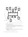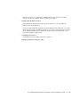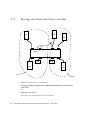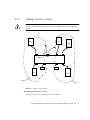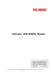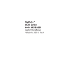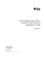
1
Sun StorEdge Network FC
Switch-8 and Switch-16
Operations Guide
Switch 3.0
Sun Microsystems, Inc.
901 San Antonio Road
Palo Alto, CA 94303
U.S.A. 650-960-1300
Part No. 816-1986-10
August 2001, Revision A
Send comments about this document to: [email protected]
Copyright 2001 Sun Microsystems, Inc., 901 San Antonio Road • Palo Alto, CA 94303-4900 USA. All rights reserved.
This product or document is protected by copyright and distributed under licenses restricting its use, copying, distribution, and decompilation.
No part of this product or document may be reproduced in any form by any means without prior written authorization of Sun and its licensors,
if any. Third-party software, including font technology, is copyrighted and licensed from Sun suppliers.
Parts of the product may be derived from Berkeley BSD systems, licensed from the University of California. UNIX is a registered trademark in
the U.S. and other countries, exclusively licensed through X/Open Company, Ltd. For Netscape Communicator™, the following notice applies:
Copyright 1995 Netscape Communications Corporation. All rights reserved.
Sun, Sun Microsystems, the Sun logo, AnswerBook2, docs.sun.com, Sun StorEdge network FC switch-8, and Solaris are trademarks, registered
trademarks, or service marks of Sun Microsystems, Inc. in the U.S. and other countries. All SPARC trademarks are used under license and are
trademarks or registered trademarks of SPARC International, Inc. in the U.S. and other countries. Products bearing SPARC trademarks are
based upon an architecture developed by Sun Microsystems, Inc.
The OPEN LOOK and Sun™ Graphical User Interface was developed by Sun Microsystems, Inc. for its users and licensees. Sun acknowledges
the pioneering efforts of Xerox in researching and developing the concept of visual or graphical user interfaces for the computer industry. Sun
holds a non-exclusive license from Xerox to the Xerox Graphical User Interface, which license also covers Sun’s licensees who implement OPEN
LOOK GUIs and otherwise comply with Sun’s written license agreements.
RESTRICTED RIGHTS: Use, duplication, or disclosure by the U.S. Government is subject to restrictions of FAR 52.227-14(g)(2)(6/87) and
FAR 52.227-19(6/87), or DFAR 252.227-7015(b)(6/95) and DFAR 227.7202-3(a).
DOCUMENTATION IS PROVIDED “AS IS” AND ALL EXPRESS OR IMPLIED CONDITIONS, REPRESENTATIONS AND WARRANTIES,
INCLUDING ANY IMPLIED WARRANTY OF MERCHANTABILITY, FITNESS FOR A PARTICULAR PURPOSE OR NONINFRINGEMENT, ARE DISCLAIMED, EXCEPT TO THE EXTENT THAT SUCH DISCLAIMERS ARE HELD TO BE LEGALLY INVALID.
Copyright 20001 Sun Microsystems, Inc., 901 San Antonio Road • Palo Alto, CA 94303-4900 Etats-Unis. Tous droits réservés.
Ce produit ou document est protégé par un copyright et distribué avec des licences qui en restreignent l’utilisation, la copie, la distribution, et la
décompilation. Aucune partie de ce produit ou document ne peut être reproduite sous aucune forme, par quelque moyen que ce soit, sans
l’autorisation préalable et écrite de Sun et de ses bailleurs de licence, s’il y en a. Le logiciel détenu par des tiers, et qui comprend la technologie
relative aux polices de caractères, est protégé par un copyright et licencié par des fournisseurs de Sun.
Des parties de ce produit pourront être dérivées des systèmes Berkeley BSD licenciés par l’Université de Californie. UNIX est une marque
déposée aux Etats-Unis et dans d’autres pays et licenciée exclusivement par X/Open Company, Ltd. La notice suivante est applicable à
Netscape Communicator™: Copyright 1995 Netscape Communications Corporation. Tous droits réservés.
Sun, Sun Microsystems, the Sun logo, AnswerBook2, docs.sun.com, Sun StorEdge network FC switch-8, et Solaris sont des marques de fabrique
ou des marques déposées, ou marques de service, de Sun Microsystems, Inc. aux Etats-Unis et dans d’autres pays. Toutes les marques SPARC
sont utilisées sous licence et sont des marques de fabrique ou des marques déposées de SPARC International, Inc. aux Etats-Unis et dans
d’autres pays. Les produits portant les marques SPARC sont basés sur une architecture développée par Sun Microsystems, Inc.
L’interface d’utilisation graphique OPEN LOOK et Sun™ a été développée par Sun Microsystems, Inc. pour ses utilisateurs et licenciés. Sun
reconnaît les efforts de pionniers de Xerox pour la recherche et le développement du concept des interfaces d’utilisation visuelle ou graphique
pour l’industrie de l’informatique. Sun détient une licence non exclusive de Xerox sur l’interface d’utilisation graphique Xerox, cette licence
couvrant également les licenciés de Sun qui mettent en place l’interface d’utilisation graphique OPEN LOOK et qui en outre se conforment aux
licences écrites de Sun.
CETTE PUBLICATION EST FOURNIE "EN L’ETAT" ET AUCUNE GARANTIE, EXPRESSE OU IMPLICITE, N’EST ACCORDEE, Y COMPRIS
DES GARANTIES CONCERNANT LA VALEUR MARCHANDE, L’APTITUDE DE LA PUBLICATION A REPONDRE A UNE UTILISATION
PARTICULIERE, OU LE FAIT QU’ELLE NE SOIT PAS CONTREFAISANTE DE PRODUIT DE TIERS. CE DENI DE GARANTIE NE
S’APPLIQUERAIT PAS, DANS LA MESURE OU IL SERAIT TENU JURIDIQUEMENT NUL ET NON AVENU.
Please
Recycle
Preface
The Sun StorEdge Network FC Switch-8 and Switch-16 Operations Guide describes how
to upgrade the Sun StorEdge the Sun StorEdge Network FC Switch-8 and Switch-16
software. It provides information on how to replace switches within a working
systemI t provides information and pointers to additional documentation you may
need for installing, configuring, and using the configuration. The book is primarily
intended for use by experienced system support engineers who already have a good
understanding of the product.
Using UNIX Commands
This document may not contain information on basic UNIX® commands and
procedures such as shutting down the system, booting the system, and configuring
devices.
See one or more of the following for this information:
■
Solaris Handbook for Sun Peripherals
■
AnswerBook2™ online documentation for the Solaris™ operating environment
■
Other software documentation that you received with your system
iii
Typographic Conventions
Typeface
Meaning
Examples
AaBbCc123
The names of commands, files,
and directories; on-screen
computer output
Edit your .login file.
Use ls -a to list all files.
% You have mail.
AaBbCc123
What you type, when
contrasted with on-screen
computer output
% su
Password:
AaBbCc123
Book titles, new words or terms,
words to be emphasized
Read Chapter 6 in the User’s Guide.
These are called class options.
You must be superuser to do this.
Command-line variable; replace
with a real name or value
To delete a file, type rm filename.
Shell Prompts
iv
Shell
Prompt
C shell
machine_name%
C shell superuser
machine_name#
Bourne shell and Korn shell
$
Bourne shell and Korn shell superuser
#
Sun StorEdge Network FC Switch-8 and Switch-16 Operations Guide • August 2001
Related Documentation
Product
Application
Title
Part Number
SANbox
Installer/User’s
information
SANbox-16STD Fibre Channel Switch
Installer’s/User’s Manual
875-3141-10
Installer/User’s
information
SANbox-8 Fibre Channel Switch
Installer’s/User’s Manual
875-3142-10
Installer/User’s
Information
SANbox 8/16 Switch Management
User’s Manual
875-3143-10
Install/configuration
Sun StorEdge Network FC Switch-8
and Switch-16 Installation and
Configuration Guide
816-0830-10
Latest Information
Sun StorEdge network FC switch-8 and
switch-16 Release Notes
816-0842-10
Software
CDInsert
Latest Information
Sun StorEdge A5000 Product Notes1
805-1018-13
Administration
Sun StorEdge T3 Disk Tray
Administrator’s Guide
806-1063-11
nstallation, Operations,
and Service
Sun StorEdge T3 Disk Tray Installations,
Operations and Service Manual
806-1062-11
Latest Information
Sun StorEdge T3 Disk Tray Release
Notes
806-1497-12
Late news - Best
Practices
Sun StorEdge A3x00/A3500 FC Best
Practices Guide
806-6419-10
Latest Information
Sun StorEdge A3500FC Release Notes1
805-7758-11
Sun StorEdge T3 Array/
Switch
Sun StorEdge T3Array to Sun StorEdge
Network FC Switch Configuration Guide
816-2096-10
Arrays
Other
Components
Preface
v
Product
Application
Title
Part Number
Traffic Management
Sun StorEdge Traffic Manager
Installation and Configuration Guide
816-1420-10
Hub information
Sun StorEdge FC-100 Hub Installation
and Service Manual
805-0315-12
Storage
Cabinet
Rackmount information
Online
Rackmount Placement Matrix
805-4748-xx
Software
RAID software
RAID Manager 6.22 User's Guide
806-0478-10
Switch
Troubleshooting
customer
Sun StorEdge network FC switch-8
and switch-16 Troubleshooting Guide
806-6923-10
Troubleshooting
internal
Sun StorEdge Network FC Switch-8 and
Switch-16 Troubleshooting Guide
816- 1701-xx
cfgadm utility
cfgadm_fp
manpage
manpage
1. Check for the latest updates at http://sunsolve.sun.com.
Accessing Sun Documentation Online
A broad selection of Sun system documentation is located at:
http://www.sun.com/products-n-solutions/hardware/docs
A complete set of Solaris documentation and many other titles are located at:
http://docs.sun.com
Sun Welcomes Your Comments
Sun is interested in improving its documentation and welcomes your comments and
suggestions. You can email your comments to Sun at:
[email protected]
vi
Sun StorEdge Network FC Switch-8 and Switch-16 Operations Guide • August 2001
Please include the part number (816-1986-10) of your document in the subject line of
your email.
Preface
vii
viii
Sun StorEdge Network FC Switch-8 and Switch-16 Operations Guide • August 2001
Contents
1.
Sun StorEdge Network FC Switch-8 and Switch -16 Switch Operations—Switch
3.0 1
0.1
Introduction
1
0.2
Product Software Installation
2
0.2.1
Minimum System Requirements
0.2.2
Firmware Download
0.2.3
Upgrading the GUI
3
▼
To Remove the 2.0 GUI
4
▼
To Install the 3.0 GUI Software
▼
To Install the 3.0 GUI Patch
▼
To Start the GUI Software 5
▼ To Use the Command Line
▼
▼
3
3
4
5
5
To Use Component Manager 2.2.
5
To Verify the Flash 6
▼ To Verify the Firmware Revision Level of the switch(es):
▼
To Load the Flash
7
0.3
Removal and Replacement of FRUs By Service Providers
0.4
Power-On-Self-Test (POST)
0.4.1
0.5
POST Diagnostics
Troubleshooting
6
8
8
8
9
ix
0.5.1
9
0.5.1.1
Synopsis
0.5.1.2
Description
0.6
Sun StorEdge A5200 Array
0.7
Switch Replacement
▼
▼
▼
9
9
13
14
To Replace a Switch in a Two-Switch Fabric
▼ To Change the Chassis ID 15
▼
To Save the Settings
▼
To Replace the Switch
▼
To Restore the Saved Settings
14
16
16
17
To Replace a Switch in a Single-Switch Fabric
▼ To Save the Settings 18
18
▼
To Replace the Switch
19
▼
To Configure the Network for a Replacement Switch
▼
To Use the Force PROM Button for the 16-port switch.
▼
To Use the Test Mode Switch for the 8-port Switch
▼
To Install the New Switch
▼
To Restore the Saved Settings
19
20
20
21
22
To Replace Both Switches in a Two-Switch Fabric 22
▼ To Replace the Switches When Both Are Responding to the
SANsurfer GUI 23
0.7.1
x
Capture
▼
To Replace the Switches When One of the Switches Within the
Fabric is Responding to the SANsurfer GUI 24
▼
To Replace the Switches When One of the Switches Is
Responding to the SANsurfer GUI 24
▼
To Replace the Switches When Both Switches Have Had
Catastrophic Failures—Saved Settings 25
▼
To Replace the Switches When Both Switches Have Had
Catastrophic Failures—No Saved Settings 26
Moving a Port with a Disk Array From One Zone to Another
Sun StorEdge network FC switch-8 and switch-16 Operations Guide • August 2001
27
▼
To Prepare the System
▼
To Remove the Port
28
28
0.7.2
Moving a Port from One Zone to Another
0.7.3
Adding a Port to a Zone
▼
0.7.4
Glossary
30
31
To Add a Host to an Existing Zone or Switch
(Non disruptive) 32
Verifying the Results
32
0.7.4.1
Verifying the Software Package Installation
0.7.4.2
Firmware
32
32
33
Contents
xi
xii
Sun StorEdge network FC switch-8 and switch-16 Operations Guide • August 2001
CHAPTER
Sun StorEdge Network FC Switch-8
and Switch -16 Switch
Operations—Switch 3.0
0.1
Introduction
This manual is intended for administrators who encounter trouble in setting up their
configurations. It provides information on how to replace a switch in the fabric.
The SAN environment consists of hosts, Fibre Channel switches, and storage
subsystems.
The SAN environment can be configured into various different forms, depending on
the type of elements used in the SAN environment.
The Sun StorEdge network Fibre Channel Switch-8 and the Sun StorEdge Network
Fibre Channel Switch-16 are the two switches used to configure the Sun SAN
environment. The Sun StorEdge Network Fibre Channel Switch-8 consists of eight
FC ports; the Sun StorEdge network Fibre Channel Switch-16 consists of 16 FC ports.
Refer to the Sun StorEdge Network FC Switch-8 and Switch-16 Installation and
Configuration Guide for information on new features and upgrades.
You can configure a maximum of four hosts or domains per switch.
Supported hosts:
■
Sun Enterprise 220R, 250, 420R, and 450
■
Sun Enterprise 3000 - Enterprise 6000
■
Sun Enterprise 3500 - 6500
-1
■
Sun Enterprise F3800 server host (only with the Sun StorEdge CPCI Dual Fibre
Channel Adapter)
■
Sun Enterprise 4800 server host with PCI Single Fibre Channel Adapter and PCI
Dual Fibre Channel Adapter
■
Sun Enterprise F4810 server host with PCI Single Fibre Channel Adapter and PCI
Dual Fibre Channel Adapter
■
Sun Enterprise F6800 server host with PCI Single Fibre Channel Adapter and PCI
Dual Fibre Channel Adapter
You can attach different types of storage subsystems to the switches.
Supported storage subsystems:
■
Sun StorEdge A5200 Array
■
Sun StorEdge T3 Array
■
Sun StorEdge A3500FC Array
You can configure different zones with the switch, with a maximum of eight zones
on the 8-port switch and eight zones on the 16-port switch.
Zoning is done by assigning ports to separate zones.
0.2
Product Software Installation
Current GUI, firmware, and documents, FC Switch 2.0 / 2.1, are available at
www.sun.com/storage/san/
at the link entitled Downloads: Software/Firmware Upgrades and Documentation.
Current GUI, firmware, and documents, FC Switch 3.0, are available at
This site provides the following versions of the Sun StorEdge network FC switch-8
and switch-16 GUI and firmware for download:
Firmware: 3.04.60
GUI:
2.08.xx
GUI revision 2.08.xx is the GUI supplied with the Sun StorEdge Network FC Switch
3.0 CD.
-2
Sun StorEdge network FC switch-8 and switch-16 Operations Guide • August 2001
0.2.1
Minimum System Requirements
See the updated Sun StorEdge Network FC Switch-8 and Switch-16 Release Notes posted
on this site for information on minimum system requirements and required Solaris 8
patches.
Your system must meet minimum requirements before proceeding with switch GUI
or firmware upgrade. Note that the StorTools diagnostics package listed in the
minimum system requirements is optional, and is not required for switch operation.
0.2.2
Firmware Download
Information on how to download the firmware can be found in the Switch
Management Users Manual, pages 2-42 and 3-7.
If an earlier version of the Sun StorEdge FC Switch SANSurfer GUI has been
installed in the system, you must perform a package remove before you install the
Sun StorEdge FC Switch 3.0 GUI.
Current switch GUI, FW and docs are posted at the Sun Download Center, accessible
by going to
http://www.sun.com/storage/san/
and clicking the Software/Firmware Upgrades and Documentation link.
0.2.3
Upgrading the GUI
If the Sun StorEdge FC Switch 2.0 (Version 2.07.50) or 2.1 (Version 2.07.54) GUI has
been installed in the system, you must perform a package removal before you install
the Sun StorEdge FC Switch 3.0 GUI.
Note – If you have the patch for the Sun StorEdge FC Switch 3.0, you can update
your version using patchadd.
Sun StorEdge Network FC Switch-8 and Switch -16 Switch Operations—Switch 3.0
-3
▼
To Remove the 2.0 GUI
1. In the root directory, type:
# pkgrm SUNWsmgr
The following message displays:
The following package is currently installed.
SUNWsmgr SANSurfer, Qlogic Fibre Channel Administration
(i86pc, sparc) 2.07
Do you want to remove this package?
2. Type:
# y [Yes]
The following message is displayed.
## Removing installed package instance <SUNWsmgr>
## Verifying package dependencies.
## Processing package information.
## Removing pathnames in class <none>
/usr/opt/SUNWsmgr/bin/esm_smgr
/usr/opt/SUNWsmgr/bin/Sun.jar
/usr/opt/SUNWsmgr/bin
/usr/opt/SUNWsmgr/app.dat
/usr/opt/SUNWsmgr <non-emty directory not removed>
## Updating system information.
Removal os <SUNWsmgr> was successful.
▼
To Install the 3.0 GUI Software
● Add the GUI package by typing:
pkgadd -d SUNWsmgr
-4
Sun StorEdge network FC switch-8 and switch-16 Operations Guide • August 2001
▼
To Install the 3.0 GUI Patch
If you have the 2.0 or 2.1 GUI already installed and you have the patch for the 3.0
GUI, you can upgrade the GUI with the 3.0 patch.
1. If you want to preserve your current user administration and fabric
configurations, copy the current user administration file (app.dat) and fabric
information file (default.fab) to another file.
2. Type:
# patchadd 110696-xx
▼
To Start the GUI Software
You can start the GUI with either the command line or Component Manager 2.2.
▼ To Use the Command Line
Type:
java -jar /usr/opt/SUNWsmgr/bin/esm_smgr
▼ To Use Component Manager 2.2.
1. Click the Launch button.
See the Component Manager documentation that came with your software for more
details on how to install and use Component Manager.
The login window appears.
If this is the first time this switch has been logged into, or if no username and
password file have been created by a superuser, use the default username and
password, which is su for each one. Otherwise, use the username and password
assigned during a previous session.
Sun StorEdge Network FC Switch-8 and Switch -16 Switch Operations—Switch 3.0
-5
2. Enter the switch IP address in the Fabric window of the GUI.
It may take a few seconds for the switch icon to become gray. You can click the
Refresh button.
3. After the switch icon becomes gray, click the icon.
Note – If the icon remains red, it is likely that the IP address is wrong, or that the
switch cannot be accessed from that subnet, or the switch lacks power or an ethernet
connection.
▼
To Verify the Flash
You must have the correct flash for the 3.0 version of the GUI in each switch of the
fabric. For cascaded switches, both switches must have the same flash version.
▼ To Verify the Firmware Revision Level of the switch(es):
Perform the following procedure for each switch.
1. Verify that the switches are not connected to each other.
2. Connect one switch to the net.
3. Launch the GUI and bring up the switch.
See “To Start the GUI Software” on page 5.
4. Open the Topology View screen.
The switch icon representing the connected switch displays in the right window
pane.
-6
Sun StorEdge network FC switch-8 and switch-16 Operations Guide • August 2001
5. Double-click the switch icon.
The Topology View screen is erased, and the Switch FacePlate Display screen
displays.
6. Make a note of the firware revision level.
The revision level appears on the second line of the text in the upper right corner of
the Switch FacePlate Display screen.
▼ To Load the Flash
1. Locate the file containing the new flash code on the management station.
The default location is /usr/opt/SUNWsmgr/flash.
2. Choose Special>Update Flash.
The application displays a standard Open dialog box that allows you to browse to
and then open the Flash Update binary file. When you select the Flash Update file,
the switch checks the file for a valid checksum. Then, if the checksum is correct, the
Flash load begins.
If the checksum is not correct, the application warns you.
3. Make sure you select the correct flash code.
The flash file for the 8-port switch is m080304xx.fls.
The flash file for the 16-port switch is m160304xx.fls.
Select the filename with the highest xx number.
The application displays information about the progress of the flash update:
■
■
■
■
File: The name of the flash update binary file
Position: Number of bytes downloaded
Total: The total number of bytes in the file
Complete: The percentage of the file sent to the chassis
When the flash load is complete, the application displays a dialog box that states
that the flash load is complete and asks whether to Reset Immediately.
4. If you want to Reset, click Yes.
Remember that a Reset operation disrupts the operation of the switch.
5. If you do not want to Reset until traffic is removed from the switch, click No.
You can perform the Reset later by choosing Special>Reset in any of the Chassis
FacePlate windows.
Sun StorEdge Network FC Switch-8 and Switch -16 Switch Operations—Switch 3.0
-7
0.3
Removal and Replacement of FRUs By
Service Providers
For removal and replacement procedures, see the “Removal/Replacement” chapter
of the SANbox Segmented Loop Switch User’s Manual.
0.4
Power-On-Self-Test (POST)
Refer to the SANbox-8/16 Segmented Loop Switch Management and User’s Manual for
information about the POST and the HeartBeat LEDs.
At startup, a switch runs a series of tests known as Power-On-Self-Test (POST)
diagnostics. These POST diagnostics check for proper switch operation, excluding
the GBICs. If no fatal errors are encountered, the switch becomes operational.
During the POST, the switch logs any errors encountered. Some POST messages are
fatal; others are non-fatal. A fatal error disables the switch so that it will not operate.
A non-fatal error allows the switch to operate, but with some decrease in
performance.
The switch uses HeartBeat LEDs to blink the error code that describes the first error
encountered. If the error encountered is non-fatal, and affects one or more ports, it
disables the bad ports and blinks the Logged-in LED to indicate which ports are
down.
See the Sun StorEdge Network FC Switch-8 and Switch-16 Installation, and Configuration
Guide and the SANbox-8/16 Segmented Loop Switch Management and User’s Manual for
information about the POST diagnostics tool.
0.4.1
POST Diagnostics
See the Sun StorEdge network FC switch-8 and switch-16 Installation, and Configuration
Guide and the SANbox-8/16 Segmented Loop Switch Management and User’s Manual for
information about the POST diagnostics tool. The POST diagnostics tool supplies
information about the following:
-8
■
The correctness of the boot firmware loaded in the PROM and the switch
firmware loaded in FLASH memory by checking the checksum.
■
The correctness of the internal switch memory.
Sun StorEdge network FC switch-8 and switch-16 Operations Guide • August 2001
■
0.5
The correctness of the switch logic, with the help of various read/write register
and loopback data-path tests.
Troubleshooting
Customer level troubleshooting instructions are provided in the Switch 3.0
Installation and Configuration Guide. Additional troubleshooting information, for
ES use only, is provided in the Sun StorEdge Network FC Switch-8 and Switch-16
Troubleshooting Guide, 816-1701-xx.
0.5.1
Capture
The line command capture gathers switch configuration data and writes it to
standard output.
0.5.1.1
Synopsis
capture [-nvram] Sw_IP_addr
0.5.1.2
Description
Capture provides a convenient way to retrieve all SANbox switch configuration
information and the current operational status, and print it in a readable form. The
information is written to standard output.
Capture is a useful way to document a configuration and the conditions when a
problem is reported, and its output should be included with all problem reports. If
it is specified, the parameter [-nvram] dumps the configuration in hex format. This
information is not useful unless the HeartBeat light indicates nvram corruption. If
nvram corruption is present, the HeartBeat light blinks 15 times, pauses, and then
repeats the error code.
The following data is recorded:
IP Address Configuration
Net IP Address:
Net Mask:
IP address of the switch
Network mask used by the switch
Sun StorEdge Network FC Switch-8 and Switch -16 Switch Operations—Switch 3.0
-9
Broadcast:
Broadcast address used by switch, if specified
Gateway:
Gateway address used by the switch
Address Discovery: RARP, Bootp, or none
ArpTimeOut:
Time in milliseconds, before ARP table entries are discarded.
Version Information
HW:
ASIC Version
PROM:
Prom Version
FLASH:
Firmware version
CHASSIS TYPE:
8 or 16 port switch
CHASSIS NUMBER:
Fabric Id:
Assigned chassis number
Assigned Fabric Id
WWN:
MAC:
WorldWide Name
MAC Address
Operating Mode
Switch Operating Mode: Indicates whether the switch is using proprietary (T-Port)
or FC-SW-2 compliant protocol (E-Port) between switches.
Nameserver Zoning Mode
Zoning Mode: Indicates whether the switch is using Port mode or WWN mode for
nameserver zoning.
Chassis Status
This section shows the status of power, temperature, and the fan(s). It also indicates
what type of GBIC is installed in each port.
-10
Sun StorEdge network FC switch-8 and switch-16 Operations Guide • August 2001
SNMP CONFIGURATION
Name:
Switch IP address
Contact:
snmp contact string, if configured
Location:
snmp location string, if configured
Trap Address:
IP address to send traps to
Read Community:
Read Community String
Write Community:
Write Community String
Trap Community:
Trap Community String
Switch description:
SysDesc, (programmed at the factory)
Switch Object ID:
SysObjectId, (programmed at the factory)
Stage Type & Time Out Values
Active:
Chassis Stage Type: Operating mode of the switch, I O Transfer (normal), Cross
Connect, or Hub Emulation
Timeout Values:
edtov:
Value in milliseconds of Fibre Channel ED_TOV
mfstov: Timeout in milliseconds, port will lock on to a source, when running
Non-Interleave Sequence mode.
ratov:
Value in milliseconds of Fibre Channel RA_TOV
rttov:
Value in milliseconds of Fibre Channel RT_TOV
Port Tuning
For each port, tuning mode is indicated, as follows:
Normal - No tuning selected
NON-I - Do not interleave sequences
MIN-I - Minimize interleave of sequences
FRAME-L - Limit frames transmitted per loop open
Sun StorEdge Network FC Switch-8 and Switch -16 Switch Operations—Switch 3.0
-11
Port Status
For each port, the following information is provided:
Port operating mode - F_Port, T_Port, TL_Port, SL_Port, or FL_Port
Administrative state - online or offline
Operational state
Status
- online or offline
- not-logged-in or logged-in
For loop Ports the AL_PAs of loop devices will be displayed For TL ports it will
indicate whether they are in Target or Initiator mode, and any public devices
proxied as a private device on the loop will be displayed.
Topology
For each port the remote chassis id, stagetype, and port address will be displayed, if
any.
Links Information
This section displays Interswitch Link ports of each switch in the fabric, and the
port, Fibre Channel Address, and WWN connected to that port.
Switch Count
This section displays switch level error and event counters.
Port count
For each port, non-zero error and event counters will be displayed.
Name Server
This display lists the contents of the name server data base on the switch, including
port, Fibre Channel address, port name, node name, and registered FC-4 types for
each device.
-12
Sun StorEdge network FC switch-8 and switch-16 Operations Guide • August 2001
NameServer Zone
This section shows the nameserver zones effective in the switch.
If port zoning is in effect, it will list all of the ports that are members of each active
nameserver zone. If WWN zoning is in effect, it will list all of the WWNs that are
members of each active nameserver zone.
Broadcast Zone
This section shows the broadcast zones effective in the switch.
It will list all of the ports that are members of each active broadcast zone.
Hard Zone
This section shows the hard zones effective in the switch. It will list all of the ports
that are members of each active hard zone.
SL Zone
This section shows the SL zones effective in the switch. It will list all of the ports that
are members of each active SL zone.
0.6
Sun StorEdge A5200 Array
The troubleshooting procedures for the Sun StorEdge A5200 Array are detailed in
the Sun StorEdge A5x00 Trouble Shooting Guide, available on-line at
http://webhome.ebay.sun.com/networkstorage/products/A5000/
After going to the Sun StorEdge A5000 website, select Trouble shooting Guide from
the Tech FAQs/Knowledge base section.
Sun StorEdge Network FC Switch-8 and Switch -16 Switch Operations—Switch 3.0
-13
0.7
Switch Replacement
Note – To perform the tasks in switch replacement you must have access to a
SANsurfer GUI with network access to a working switch in the Fabric. You must
also have SuperUser (root) access within the GUI.
Note – You can use only a switch with factory default settings as a replacement
switch.
■
The procedures for switch replacement need to be used with the SANBox-8/16
Switch Management User’s Manual Sun StorEdge network FC switch 3.0 (part number
875-3143, Rev. R19).
■
Switch replacement is not disruptive only in a high availability configuration.
If you are replacing a switch in:
■
A two-switch Fabric, see “To Replace a Switch in a Two-Switch Fabric” on
page 14.
■
A single-switch Fabric, see “To Replace a Switch in a Single-Switch Fabric” on
page 18.
If you are replacing both switches in:
■
A two-switch Fabric, see “To Replace Both Switches in a Two-Switch Fabric” on
page 22.
To move a port:
■
Containing a disk array from one zone to another, see Section 0.7.1, “Moving a
Port with a Disk Array From One Zone to Another” on page -27.
■
From one zone to another, see Section 0.7.2, “Moving a Port from One Zone to
Another” on page -30.
To add a port to a zone, see Section 0.7.3, “Adding a Port to a Zone” on page -31.
To verify that service or system administrators techniques were successful, see
Section 0.7.4, “Verifying the Results” on page -32.
▼
To Replace a Switch in a Two-Switch Fabric
Three conditions may require you to replace a switch.
-14
Sun StorEdge network FC switch-8 and switch-16 Operations Guide • August 2001
■
The switch to be replaced within the Fabric is responding to the SANsurfer GUI
either through the Ethernet or in-band from a second switch.
■
The switch to be replaced within the Fabric has experienced a catastrophic failure
and is not responding to the SANsurfer GUI, either through the Ethernet or inband from a second switch. If you have an archive of the Fabric and zoning
template, skip the Saving Settings section because there is no way of recovering
the switch’s current settings.
■
The switch to be replaced within the Fabric has experienced a catastrophic failure
but you do not have an archive of the Fabric or a zoning template. Skip the
Saving Settings section and the Restoring Saved Settings" section because you
cannot recover the switch’s current settings and there are no saved settings.
1. Launch the SANsurfer GUI.
Type:
# /usr/opt/SUNWsmgr/bin/esm_smgr
2. Log in.
Use the username su and the password su.
The Fabric screen appears.
3. Select the Sun logo under the status column.
The Topology window appears. If it does not appear, select Refresh and select the
Sun logo again.
If subsequent attempts to enter the Topology window fail, troubleshoot the network
connection. The management switch may be bad.
4. If the failed switch is currently selected, select the second switch that is not failed
in the fabric.
a. Change the IP address on the Fabric line by selecting the line.
b. Select the IP address or hostname under the IP Address column and use the
Delete button.
You can now select the empty IP Address box and enter the second switch’s
address.
▼ To Change the Chassis ID
Each switch in the Fabric must have a unique chassis ID. The default chassis ID is 0.
If the switch you are using to manage the Fabric has a chassis ID of 0, you must
change it temporarily to a another number. All chassis IDs are restored when you
restore the saved settings. See “To Restore the Saved Settings” on page 17.
Sun StorEdge Network FC Switch-8 and Switch -16 Switch Operations—Switch 3.0
-15
1. Double-click the Sun logo to display the Topology window.
2. Double-click the switch icon with the RJ45 connector to display the Faceplate
window.
Do not double click the RJ45 connector.
3. Change the Chassis ID to a unique number from 1 to 63.
Do not choose a Chassis ID number that is currently assigned to the other switch.
4. Save the changes by clicking the Apply button.
Select yes to messages about disrupting traffic and reconfiguring the switch.
5. Click Back to display the Topology window.
▼ To Save the Settings
1. In the Topology window, from the Special menu, select the Archive Fabric option.
This collects and stores the port configuration, network access, and chassis settings
of all the switches within the Fabric. It does not gather zoning or SNMP settings.
2. Select a unique .cfg filename and save the configuration.
3. Save the SNMP information.
a. Select the switch you are replacing.
The Faceplate window appears. Wait for it to populate fully.
b. Select the RJ45 icon in the switch Faceplate window to enter the Network
Configuration window.
Document the SNMP configuration information. This information is not saved in
any configuration file; you must manually enter the information again after you
replace the switch.
4. Select Return to Fabric Screen from the View menu.
5. Double-click the Sun logo in the status column to display the Topology window.
6. Click the Zoning button to enter the Zoning window.
7. From the Special pull-down menu, select the Save Template to File option.
Select a unique .tp2 file name to save the zoning template.
Zoning settings for all the switches in the Fabric are collected and stored.
8. Click the Back button to return to the Topology window.
▼ To Replace the Switch
1. Turn off the power on the failed switch.
-16
Sun StorEdge network FC switch-8 and switch-16 Operations Guide • August 2001
2. Within SANsurfer, highlight the switch you just powered off, and click the Delete
button to confirm the deletion of the switch.
3. Label all the cables for replacement.
4. Disconnect all the Fibre cables from the failed switch.
Remove all the GBICs from their ports.
5. Disconnect the Ethernet cable from the failed switch.
6. Disconnect all the power cables from the failed switch.
7. Remove the old switch and document serial numbers.
8. Write down the new switch serial number.
9. Install the new switch in the old switch’s place.
10. Reconnect the power cables and the Ethernet cable to the new switch.
11. Reinsert the GBICs into the new switch and connect the Fibre cables.
Use the same ports that were used on the failed switch.
12. Power on the new switch.
▼ To Restore the Saved Settings
Allow the GUI to change the stage type and update the firmware of the switch. The
GUI will prompt you. The flash is stored in the directory
/usr/opt/SUNWsmgr/flash
The files begin with m08 or m16. The m08 file is for an 8-port switch and the m16 is
for a 16-port.
1. While in the Topology window, from the Special pull-down menu, select Restore
Fabric.
In the dialog box, you are prompted with the saved configuration files.
.cfg is listed on the left side.
2. Find the configuration of the replaced switch on the left side of the dialog box and
select the name of the new switch on the right side of the dialog box. Press OK.
The old switch’s settings are restored onto the new switch.
3. Restore zoning by entering the Zoning window.
4. From the Zoning window, select the Load Template from File option from the
Special pull-down menu.
The old switch’s zoning settings are restored onto the new switch.
Sun StorEdge Network FC Switch-8 and Switch -16 Switch Operations—Switch 3.0
-17
▼
To Replace a Switch in a Single-Switch Fabric
This section covers the replacement of a failed switch within a single switch Fabric.
Three conditions may require you to replace a switch in a single-switch Fabric.
■
The switch to be replaced is responding to the SANsurfer GUI through the
Ehernet.
■
The switch to be replaced has experienced a catastrophic failure and is not
responding to the SANsurfer GUI, but you have an archive of the Fabric and
zoning template. Skip the Saving settings section because you cannot recover the
switch’s current settings.
■
The switch to be replaced has experienced a catastrophic failure, but you do not
have an archive of the Fabric or a zoning template. Skip the Saving Settings
section and the Restoring Saved Settings section because you cannot recover the
switch’s current settings, and no saved settings exist.
1. Launch the SANsurfer GUI.
Type:
# /usr/opt/SUNWsmgr/bin/esm_smgr
2. Log in.
Use the username su and the password su.
The Fabric screen appears.
3. Select the Sun logo under the status column.
The Fabric window appears. If it does not appear, select Refresh and select the Sun
logo again.
▼ To Save the Settings
1. In the Topology window, from the Special menu, select the Archive Fabric option.
This collects and stores the port, network access, and chassis settings of all the
switches within the Fabric. It does not gather zoning or SNMP settings.
2. Select a unique .cfg filename to save the configuration.
3. Save the SNMP information.
a. Select the switch you are replacing.
The Faceplate window appears. Wait for it to populate fully.
b. Select the RJ45 icon in the switch Faceplate window to enter the Network
Configuration window.
Document the SNMP configuration.
-18
Sun StorEdge network FC switch-8 and switch-16 Operations Guide • August 2001
4. Select Return to Fabric Screen from the View menu.
5. Click the Sun logo in the status column.
6. Click the Zoning button to enter the Zoning window.
7. From the Special pull-down menu, select the Save Template to File option.
Select a unique .tp2 file name to save the zoning template.
Zoning settings for all the switches in the Fabric are collected and stored.
8. Click the Back button to return to the Topology window.
▼ To Replace the Switch
1. Turn off the power to the switch.
2. Within SANsurfer, highlight the switch you just powered off, and click the Delete
button to confirm the deletion of the switch.
3. Label all the cables for replacement.
4. Disconnect all the Fibre cables and remove all the GBICs from their ports.
5. Disconnect the Ethernet cable.
6. Disconnect all the power cables [to the switch?].
7. Remove the old switch and write down the serial numbers.
▼ To Configure the Network for a Replacement Switch
1. Reconfigure the host IP address.
a. Save the workstations network configuration information by typing:
# ifconfig -a > /tmp/save_address
b. Verify the saved information by typing:
# cat /tmp/save_address
c. Reconfigure the workstations IP address and netmask by typing:
# ifconfig hme0 10.0.0.2 netmask 255.0.0.0 up
Sun StorEdge Network FC Switch-8 and Switch -16 Switch Operations—Switch 3.0
-19
d. Verify the change by typing:
# ifconfig -a
2. Enable the FORCED PROM mode on the switch.
Using FORCED PROM mode allows the switch to use firmware stored in PROM,
rather than flash memory, while you configure the switch IP address. You can use
either the Force PROM button (16-port switch) or the Test Mode switch (8-port
switch).
▼ To Use the Force PROM Button for the 16-port switch.
The button is on the back panel of the switch chassis below port 16.
a. Isolate the switch chassis from the fabric and power the switch off.
b. Press and hold the Force PROM button, and power the switch on.
c. Allow the switch to complete the POST, and release the Force PROM button
(this should take 5-10 seconds).
d. Observe the heartbeat LED for error codes (5 blinks is normal when in Force
PROM mode).
Correct the conditions or reconfigure the switch as required.
▼ To Use the Test Mode Switch for the 8-port Switch
The test mode switch is a small rotary switch on the back of the switch chassis. The
test mode switch position determines which operating mode the switch enters when
the switch chassis is powered on. Normal operation is indicated by the alignment of
the small notch on the test mode switch with the dot on the faceplate.
a. Using a small screwdriver, rotate the test mode switch four clicks clockwise to
the Force PROM position.
b. Turn the power switch off for three seconds, and then back on to reset the
switch chassis.
c. Observe the heartbeat LED for error codes (5 blinks is normal when in Force
PROM mode).
d. If you do not observe the blink code, re-align the small notch on the test mode
switch with the dot on the faceplate and return to Step a.
e. Rotate the test mode switch four clicks counter-clockwise to the normal
operating position.
-20
Sun StorEdge network FC switch-8 and switch-16 Operations Guide • August 2001
3. Plug the switch into the same Ethernet segment or subnet as the host and verify
connectivity to the switch by typing:
# ping 10.0.0.1
If the ping fails, replace the local area network with a crossover cable between the
switch and the host Ethernet port. See the SANBox 8/16 Switch Management User’s
Manual, Switch Preparation section, under “Using a Crossover Cable.”
4. Open the SANsurfer GUI.
5. From the Fabric screen enter 10.0.0.1 for the IP address of the switch and press
Return twice.
The PROM logo appears in the status column.
6. Select the text that appears in the Fabric Name column.
The Network configuration screen appears. See the SANBox 8/16 Switch Management
User’s Manual, Switch Preparation section, under “To Activate SANsurfer to Modify
a Switch IP Address” for instructions on filling in the fields necessary to configure
the IP address of the switch. Remember to click Apply after filling in all the fields.
7. Reset the Switch.
You can now reset the switch using the power button to return the switch to normal
operating mode. You can observe the heartbeat LED blinking approximately once a
second.
8. Restore the Workstation IP Address to the value stored in /tmp/save_address
by typing:
# ifconfig hme0 <ip address> netmask <orig netmask> up
9. Verify network configuration changes by typing:
# ifconfig -a
# cat /tmp/save_address
A comparison of the current configuration and the saved configuration appears.
▼ To Install the New Switch
1. Write down the new switch serial number.
Sun StorEdge Network FC Switch-8 and Switch -16 Switch Operations—Switch 3.0
-21
2. Install the new switch in the old switch’s place.
3. Reconnect the power cables and the Ethernet cable.
4. Reinsert the GBICs into their previous ports and connect the Fibre cables.
5. Power on the new switch.
▼ To Restore the Saved Settings
You may have to let the GUI change the stage type and update the firmware of the
switch. The GUI will prompt you. The flash is stored in the directory
/usr/opt/SUNWsmgr/flash
The files begin with m08 or m16. The m08 file is for an 8-port switch and the m16 is
for a 16-port.
1. While in the Topology window, from the Special pull-down menu, select Restore
Archive.
In the dialog box, you are prompted with the saved configuration files.
.cfg is listed on the left side.
2. Find the configuration of the replaced switch on the left side of the dialog box and
select the name of the new switch on the right side of the dialog box. Press OK.
The old switch’s settings are restored onto the new switch.
3. Restore zoning by entering the Zoning window.
4. From the Zoning window, select Load Template from File from the Special pulldown menu.
The old switch’s zoning settings are restored onto the new switch.
▼
To Replace Both Switches in a Two-Switch Fabric
Five conditions may require you to replace a switch.
-22
■
Both the switches to be replaced within the Fabric are responding to the
SANsurfer GUI.
■
One of the switches to be replaced within the Fabric is responding to the
SANsurfer GUI either through the Ethernet or in-band from a second switch. You
have an archive of the Fabric and zoning template.
■
One of the switches to be replaced within the Fabric has experienced a
catastrophic failure and is not responding to the SANsurfer GUI, either through
the Ethernet or in-band from a second switch. You do not have an archive of the
Fabric or a zoning template.
Sun StorEdge network FC switch-8 and switch-16 Operations Guide • August 2001
■
Both the switches to be replaced within the Fabric have had catastrophic failures
and you have a copy of the Fabric archive and zoning template.
■
Both switches have had catastrophic failures and you do not have an archive of
the Fabric or a zoning template. settings.
▼ To Replace the Switches When Both Are Responding to the
SANsurfer GUI
The First Switch
1. Launch the SANsurfer and connect to the switch.
See “To Replace a Switch in a Two-Switch Fabric” on page 14 and follow the steps
for launching and connecting.
2. Save the settings.
See “To Replace a Switch in a Two-Switch Fabric” on page 14 and follow the steps
for saving the settings.
3. Replace the switch.
See “To Replace a Switch in a Two-Switch Fabric” on page 14 and follow the steps
for replacing the switch.
4. Restore the saved settings.
See “To Replace a Switch in a Two-Switch Fabric” on page 14 and follow the steps
for restoring the saved settings. The settings restored are from saved configuration
files.
The Second Switch
5. Launch the SANsurfer and connect to the switch.
See “To Replace a Switch in a Two-Switch Fabric” on page 14 and follow the steps
for launching and connecting.
6. Replace the switch.
See “To Replace a Switch in a Two-Switch Fabric” on page 14 and follow the steps
for replacing the switch.
7. Restore the saved settings.
See “To Replace a Switch in a Two-Switch Fabric” on page 14 and follow the steps
for restoring the saved settings. The settings restored are from saved configuration
files.
Sun StorEdge Network FC Switch-8 and Switch -16 Switch Operations—Switch 3.0
-23
▼ To Replace the Switches When One of the Switches Within
the Fabric is Responding to the SANsurfer GUI
The First Switch
1. Launch the SANsurfer and connect to the switch.
See “To Replace a Switch in a Two-Switch Fabric” on page 14 and follow the steps
for launching and connecting.
2. Replace the switch.
See “To Replace a Switch in a Two-Switch Fabric” on page 14 and follow the steps
for replacing the switch.
3. Restore the saved settings.
See “To Replace a Switch in a Two-Switch Fabric” on page 14 and follow the steps
for restoring the saved settings. The settings restored are from saved configuration
files.
The Second Switch
1. Launch the SANsurfer and connect to the switch.
See “To Replace a Switch in a Two-Switch Fabric” on page 14 and follow the steps
for launching and connecting.
2. Replace the switch.
See “To Replace a Switch in a Two-Switch Fabric” on page 14 and follow the steps
for replacing the switch.
3. Restore the saved settings.
See “To Replace a Switch in a Two-Switch Fabric” on page 14 and follow the steps
for restoring the saved settings. The settings restored are from saved configuration
files.
▼ To Replace the Switches When One of the Switches Is
Responding to the SANsurfer GUI
The Failed Switch
1. See “To Replace a Switch in a Two-Switch Fabric” on page 14.
Perform all the steps in the section, until the catestrophically failed switch has been
replaced.
-24
Sun StorEdge network FC switch-8 and switch-16 Operations Guide • August 2001
The Second Switch
1. Launch the SANsurfer and connect to the switch.
See “To Replace a Switch in a Two-Switch Fabric” on page 14 and follow the steps
for launching and connecting.
2. Replace the switch.
See “To Replace a Switch in a Two-Switch Fabric” on page 14 and follow the steps
for replacing the switch.
3. Restore the saved settings.
See “To Replace a Switch in a Two-Switch Fabric” on page 14 and follow the steps
for restoring the saved settings. The settings restored are from saved configuration
files.
▼ To Replace the Switches When Both Switches Have Had
Catastrophic Failures—Saved Settings
The First Switch
1. Launch the SANsurfer and connect to the switch.
See “To Replace a Switch in a Single-Switch Fabric” on page 18 and follow the steps
for launching and connecting.
Note – Remember that neither switch is functional. You may have to omit one or
more steps.
2. Replace the switch.
See “To Replace a Switch in a Single-Switch Fabric” on page 18 and follow the steps
for replacing the switch.
3. Configure the replacement switch for the Network.
See “To Configure the Network for a Replacement Switch” on page 19.
4. Restore the saved settings.
See “To Replace a Switch in a Single-Switch Fabric” on page 18 and follow the steps
for restoring the saved settings. The settings restored are from saved configuration
files.
The Second Switch
One switch on the network, and you must replace the second switch.
Sun StorEdge Network FC Switch-8 and Switch -16 Switch Operations—Switch 3.0
-25
1. Launch the SANsurfer and connect to the switch.
See “To Replace a Switch in a Two-Switch Fabric” on page 14 and follow the steps
for launching and connecting.
2. Replace the switch.
See “To Replace a Switch in a Two-Switch Fabric” on page 14 and follow the steps
for replacing the switch.
3. Configure the replacement switch for the Network.
See “To Configure the Network for a Replacement Switch” on page 19.
▼ To Replace the Switches When Both Switches Have Had
Catastrophic Failures—No Saved Settings
The First Switch
1. Launch the SANsurfer and connect to the switch.
See “To Replace a Switch in a Two-Switch Fabric” on page 14 and follow the steps
for launching and connecting.
2. Save the settings.
See “To Save the Settings” on page 16.
3. Replace the switch.
See “To Replace a Switch in a Two-Switch Fabric” on page 14 and follow the steps
for replacing the switch.
4. Install the new switch.
See “To Install the New Switch” on page 21 .
The Second Switch
You must replace the second switch.
1. Launch the SANsurfer and connect to the switch.
See “To Replace a Switch in a Two-Switch Fabric” on page 14. Use the IP address of
the switch you just replaced.
Note – Pay close attention to the Chassis ID section.
2. Replace the switch.
-26
Sun StorEdge network FC switch-8 and switch-16 Operations Guide • August 2001
3. See “To Replace a Switch in a Two-Switch Fabric” on page 14.
Both switches have been replaced and are on the network. Because of the lack of the
saved configuration you must reconfigure the switches.
0.7.1
Moving a Port with a Disk Array From One Zone
to Another
Caution – Removing a Zone or port is a destructive process. You must perform all
the steps before removing the port from the Zone.
Sun StorEdge Network FC Switch-8 and Switch -16 Switch Operations—Switch 3.0
-27
Array
Array
Array
Array
Array
Switch
Host
Host
Array
Zone 1
Array
Array
FIGURE 0-1
Zone 2
Moving a Port with Disk Array—Switch with Two Hosts and Two Zones
▼ To Prepare the System
1. Unmount all the filesystems mounted on the devices present on that port.
2. Unconfigure and update the applications that were using the devices on that port.
3. Bring down all the hosts present in Zone 1.
▼ To Remove the Port
1. Using the SANSurfer application launched from another host, remove the port
from Zone 1.
See SANbox 8/16 Switch Management User’s Manual.
-28
Sun StorEdge network FC switch-8 and switch-16 Operations Guide • August 2001
If the port in Zone 1 is connected to A3500FC Disk Array and Zone 2 already
contains at least one A3500FC Disk array, then go to Step 3.
2. Bring down the host in Zone 2.
If the SANSurfer application is running on any other host, you can make the
changes from that application.
If you have the SANSurfer application up and running on any other host, you can go
ahead with the changes from that application. If you have configured only two zones
on the switch and there are no other hosts, bring up the host on the Zone 1 and
launch the SANSurfer application.
3. Add the port to Zone 2.
See SANbox 8/16 Switch Management User’s Manual.
4. Bring up the hosts on Zones 1 and 2.
Sun StorEdge Network FC Switch-8 and Switch -16 Switch Operations—Switch 3.0
-29
0.7.2
Moving a Port from One Zone to Another
Array
Array
Array
Switch
Host
Host
Array
Array
Zone 1
Zone 2
FIGURE 0-2
Moving a Port to Another Zone
1. Using the SANSurfer application launched from another host, remove the port
from Zone 1.
See .
2. Add the port to zone 2.
See SANbox 8/16 Switch Management User’s Manual.
.
-30
Sun StorEdge network FC switch-8 and switch-16 Operations Guide • August 2001
0.7.3
Adding a Port to a Zone
Caution – Removing a Zone or port is a destructive process. The addition will have
a LIP circulated through the loop by the switch. Adding a port is a nondestructive
process.
Array
Array
Array
Switch
Host
Host
Array
Array
Zone 1
Zone 2
FIGURE 0-3
Adding a Port to a Zone
● Add the port to zone 1 or Zone 2.
See the SANbox 8/16 Switch Management User’s Manual.
Sun StorEdge Network FC Switch-8 and Switch -16 Switch Operations—Switch 3.0
-31
▼ To Add a Host to an Existing Zone or Switch
(Non disruptive)
● Add the port that contains the host to the zone.
See the SANbox 8/16 Switch Management User’s Manual.
0.7.4
Verifying the Results
Verifying that the service or system administrators techniques were successful is
different for the software package and patches and the device driver packages.
0.7.4.1
Verifying the Software Package Installation
You can use pkginfo -l <packagename> to see which driver packages have been
installed on the system.
0.7.4.2
Firmware
You can check which firmware revision has been installed from the switch GUI.
For more information on Fibre Channel and troubleshooting the switch, see the Sun
StorEdge network FC switch-8 and switch-16 Troubleshooting Guide.
-32
Sun StorEdge network FC switch-8 and switch-16 Operations Guide • August 2001
Glossary
This glossary contains a definitions for terms used in this guide.
Terms
AL_PA
FL_Port
F_Port
Arbitrated Loop Physical Address; 8-bit value used to identify a device.
On a Fibre Channel switch, a port that supports Arbitrated Loop devices.
On a Fibre Channel switch, a port that supports an N_Port. A Fibre Channel
port in a point-to-point or Fabric connection.
N_Port
NL_Port
G_Port
SL_Port
T_Port
TL_Port
A Fibre Channel port in a point-to-point or Fabric connection.
Node loop port; a port that supports Arbitrated Loop protocol.
On a Fibre Channel switch, a port that supports either F_Port or E_Port
Segmented Loop Port. A port connected to a private loop device.
An inter-switch port, one that is used to attach a port on one switch to a port
on another switch.
A Translated Loop Port on the Sun StorEdge T3 array.
Public Loop
An Arbitrated Loop attached to a Fabric switch.
Private Loop
An Arbitrated Loop without a Fabric switch
Segmented Loop
Zone
A set of ports that behave as one private loop.
A set of ports and their connected devices that have been grouped together
to control information exchange.
Glossary-33
Zoning
Zoning allows the user to divide the Fabric ports into zones for more efficient
and secure communication among functionally grouped nodes. There are
several types of zones and a port may be defined in any. No port can be in all
zone types simultaneously.
Hard Zones
Hard Zones allow the division of the Fabric (one or more Switch chassis) into
as many as 16 Fabric-wide zones that define the ports that can communicate
with each other. A particular port may be placed in only one Hard Zone (no
overlapping Hard Zones). If Hard Zones are enabled, Name Server Zones and
SL Zones will not communicate across defined Hard Zone boundaries.
Broadcast Zone
Zone type used to filter broadcast traffic away from end nodes that cannot use
or interpret it. A port will broadcast to all ports in the same Broadcast Zone(s)
in which the port is defined. Broadcast zoning is primarily used for doing IP
over Fibre Channel or when mixing IP and SCSI traffic on the switch. These
zones are not yet useful or interesting in Suns current SAN implementations.
SL_Port Zone
A set of ports and their connected devices (zone) that behave as a single
private loop. SL Zones on the switch allow the division of the Fabric (one
or more Switch chassis) into Fabric-wide zones that define the ports that
can communicate with each other.
Cascade
Connection of two or more switches together to increase the number of
available ports or to allow for increased distances between components of the
SAN.
Name Server
Zones allow the division of the Fabric (one or more Switch chassis) into as
many as 256 Fabric-wide zones that define which ports or devices receive
Name Server information. If Hard Zones are enabled, Name Server Zones will
not communicate across defined Hard Zone boundaries.
Fabric
Fibre channel network built around one or more switches. It is also common to
refer to something as a "Fabric device" or being in "Fabric mode". When used
in this context, it simply means a public device, capable of logging into a
Fabric and having public loop characteristics (as opposed to a private loop
legacy device).
Glossary-34
Sun StorEdge Network FC Switch-8 and Switch-16 Operations Guide • August 2001