1
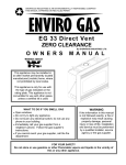
SHERWOOD INDUSTRIES IS AN ENVIRONMENTALLY RESPONSIBLE COMPANY
THIS MANUAL IS PRINTED ON RECYCLED PAPER
8 2 8
By SHERWOOD INDUSTRIES LTD.
Direct Vent
O W N E R S
M A N U A L
Installation And Operating Instructions For Models:
828 MH (MOBILE HOME)
828 DV. FS. (Freestanding)
828 DV. INS. (Insert)
WARNING
WHAT TO DO IF YOU SMELL GAS
• Open windows/Extinguish any open flame
• Do not try to light any appliance.
• Do not touch any electrical switch; do not use any
phone in your building.
• Immediately call your gas supplier from a
neighbor's phone. Follow the gas supplier's
instructions.
• If you cannot reach your gas supplier, call the fire
department.
If the information in this
manual is not followed exactly,
a fire or explosion may result
causing property damage,
personal injury or loss of life. A
qualified installer, service
agency or the gas supplier
must perform installation and
service.
FOR YOUR SAFETY
Do not store or use gasoline or other Flammable vapors and liquids
in the vicinity of this or any other appliance.
PLEASE KEEP THESE INSTRUCTIONS FOR FUTURE REFERENCE.
SAFETY PRECAUTIONS
FOR SAFE INSTALLATION AND OPERATION OF YOUR "ENVIROGAS" ROOM HEATER,
PLEASE, CAREFULLY READ THE FOLLOWING INFORMATION:
• All "ENVIROGAS" gas-fired appliances must be
installed in accordance with these instructions. Carefully
read all the instructions in this manual first. Consult the
building authority having jurisdiction to determine the need
for a permit prior to commencing the installation.
•
To prevent injury, if the pilot or pilot and
burners have gone out on their own, open the
glass door and wait 5 minutes to air out before
attempting to re-light stove.
• NOTE Failure to follow these instructions could cause
a malfunction of the fireplace that could result in death,
serious bodily injury, and/or property damage.
• Failure to follow these instructions may also void your
fire insurance and/or warranty.
• Always keep the area around these appliances
clear of combustible material, gasoline or other
flammable vapors and liquids.
• These appliances should not be used as a drying
rack for clothing or for hanging Christmas stockings or
decorations.
GENERAL
• Installation and repair should be done by a
qualified service person. The appliance should
be inspected before use and at least annually by
a qualified service person. More frequent
cleaning may be required due to excessive lint
from carpeting, bedding material, etc. It is
imperative that control compartments, burners
and circulating air passageways of the appliance
be kept clean.
• Due to the paint curing on the stove a faint odor
and slight smoking will likely be noticed when the stove
is first used. Open a window until the slight smoking
stops.
• Always connect this gas stove to a vent system
and vent to the outside of the building envelope. Never
vent to another room or inside a building. Make sure
you use the vent pipe that is specified. Make sure that
the vent is properly sized and is of adequate height to
provide the proper draft. Inspect the venting system
annually for blockage and any signs of deterioration.
• Due to high temperatures the appliance
should be located out of high traffic areas and
away from furniture and draperies.
Children and adults should be alerted to hazards
of high surface temperatures and should stay
away to avoid burns or clothing ignition.
• Do not operate with cracked or broken
glass. Under no circumstances should this
appliance be modified. Parts that have to
be removed for servicing must be replaced
prior to operating this appliance. Only
parts supplied by Envirogas should be
used in this appliance and replacements
should only be performed by a licensed or
qualified service person.
• Young children should be carefully
supervised when they are in the same room as
the appliance.
• Clothing or other flammable material should
not be placed on or near the appliance.
• Never use solid fuels such as wood, paper,
cardboard, coal, or any other flammable liquids etc., in
this appliance.
FOR YOUR SAFETY
• A qualified installer, service agency or the gas
supplier must perform installation and service.
• Do not use this heater if any part has been under
water. Immediately call a qualified service technician
to inspect the heater and to replace any part of the
control system and any gas control that has been
under water.
•
Do not abuse glass by striking or slamming door
shut
• This installation must conform with local codes or, in
the absence of local codes with the current CAN/CGA B149 installation code in Canada or the National Fuel Gas
Code ANSI Z223.1.2 in the USA.
• To prevent injury, do not allow anyone who is
unfamiliar with the operation to use the stove.
2
TABLE OF CONTENTS
1 Code Approvals ...........................................................................................................................................3
Specifications...............................................................................................................................................3
2 Dimensions and Clearances to Combustibles .............................................................................................4
Zero Clearance Box Assembly .................................................................................................................... 5
3 Deciding Where to Locate Your Stove .........................................................................................................6
4 Assembly Instructions ..................................................................................................................................6
Fireplace Insert ............................................................................................................................................ 7
5 Installing burner control assembly ............................................................................................................... 8
6 Installation of Log Sets and Embers.............................................................................................................8
7 Electrical Requirements ...............................................................................................................................9
8 Gas Line Connection....................................................................................................................................10
9 Air Shutter Adjustment .................................................................................................................................11
10 Venting........................................................................................................................................................12
11 Mobile Home Fuel Conversion ....................................................................................................................19
12 Operating Instructions .................................................................................................................................20
13 Routine Maintenance ..................................................................................................................................21
14 Trouble Shooting.........................................................................................................................................22
15 Parts and Accessories ................................................................................................................................23
16 Warranty .....................................................................................................................................................24
17 Installation data sheet................................................................................................................................ 25
1. CODES AND APPROVALS
•
Direct Vent Type is designated by the suffix DV. This type of appliance draws all of the air for combustion from outside of the dwelling
through specially designed vent pipe.
These appliances have been tested by International Approval Services and found to comply with the established standards for DIRECT
VENT WALL FURNACES in CANADA and the USA as follows:
LISTED GAS FIRED GRAVITY DIRECT VENT WALL FURNACE ( 828 DV. Nat. & LPG. )
TESTED TO: ANSI Z21.44-1991 GAS FIRED FAN TYPE DIRECT VENT
WALL FURNACE. CAN/CGA 2.19-M81 GAS FIRED GRAVITY
2
AND FAN TYPE DIRECT VENT WALL FURNACE. CGA INTERIM REQUIREMENT NO. 41-1991 DIRECT VENT GAS FIREPLACES
CGA INTERIM REQUIREMENT NO. 55 - ADDITION REQUIREMENTS FOR DIRECT VENT FIREPLACES. CGA 2.17-M91 GAS FIRED
APPLIANCES FOR USE AT HIGH ALTITUDE
ENVIROGAS 828 DIRECT VENT UNITS;
•
•
•
•
•
•
Have all been certified for use with either natural or propane gases. (See control panel and rating label.)
Are not for use with solid fuels.
Are approved for bedroom or bedsitting room.
Must be installed in accordance with local codes if any. If none exist use current installation code CAN/CGA B149 in Canada or ANSI
Z223.1 / NFPA 54 in the USA.
Must be properly connected to an approved venting system.
Manufactured (mobile) home installation must be in accordance with the Manufactured Home Construction and Safety Standard, UL
307B, Title 24 CFR, Part 3280 and/or The Standard for Manufactured Home Installations, ANSI A225.1/NFPA 501A. The unit must be
bolted to the floor of the mobile home and must be electrically grounded to the steel chassis.
FREESTANDING;
•
•
Are approved for installation on combustible materials.
Are not approved for closet or recessed installations.
INSERT;
•
•
are for installation in solid fuel burning fireplaces only;
can be installed in Envirogas Zero Clearance Can kit 828-134 as a zero clearance unit.
3
2. DIMENSIONS AND CLEARANCES TO COMBUSTIBLES
FIREPLACE INSERT: The stove can only be installed in a solid fuel burning fireplace .
Mantle pillar to stove
10”
Stove top to 8” wide mantle
12”
Minimum firebox size W 26” x H 20” x D 20”
(NOTE; standard size shown – optional 33”H x 46”W available)
FREESTANDING:
Side wall to stove
10"
Rear wall to stove
4"
Combustible to stove Top 22"
Floor to stove
0"
Corner clearance
2"
Alcove depth
48"
Maintain sufficient clearances for service and maintenance
FIREPLACE INSERT / WITH ZERO CLEARANCE KIT ( Part # 828- 134 )
After deciding where to locate the fireplace insert you must frame an opening to except the Zero Clearance Box to reduce the clearance to
combustibles. The framing dimensions are as follows; 32 1/4” wide, 29 3/8” high and a depth of 14 3/4”.
The header at the top front of the opening must be a 2x4 on edge or a cut out in the 2x4 to maintain clearances to combustibles to the vent
pipe. A minimum of 1 1/2” clearance must be maintained to the vent pipe.
Before you install the Zero
Clearance Box you must
determine the finished hearth
height.(including tiles, subfloor, etc.)
The bottom of the box must be the
same height as the finished
hearth height.
4
ZERO CLEARANCE BOX ASSEMBLY;
First take the kit from the box and place the surround panels aside so as not to damage the panels. There will also be a bag of screws, nuts
and bolts in the box. The bottom section of the kit will have two 3 inch square boxes mounted to the bottom. First attach the bottom to the
back with the screws provided, the hole should be located in the
lower right hand corner looking at it from the front. The side can then
be mounted to the bottom panel and the back panel. There are three
(3) vee shaped standoffs with six screw holes in each, and they
should be mounted on both sides as well as the back. There are also
two (2) triangular support brackets that must be fastened to the inside
of the box. There is a right hand and a left hand bracket, they should
be mounted with the flanges pointing upwards.
There are two long “L” shaped framing brackets that are screwed in
from the outside front edge of each side. Each bracket has three
adjustment holes depending on the thickness of the finished wall. The
hole that is furthest forward are for a wall thickness of 1/2” drywall
and the other holes are for other wall thickness up to 7/8” thick. The
Zero Clearance kit must be flush with the finished wall.
The next step is to put the top on the box. It will fit inside of the back
and side panels and is screwed in from the outside. The two short
vee shaped standoffs are screwed on to the top of the zero clearance kit. There are two large “L” type brackets that are to be screwed
down on either side of the hole were the flue pipe exits the box. These two brackets are to locate the clamping bracket that holds the
Simpson Duravent Telescoping pipe and allows the 828 unit to be disconnected and
removed if the unit needs to be repaired.
The next step is to attach the top extension to the Zero Clearance box. This is screwed
to the top front edge. The top framing bracket is in turn screwed to the top extension.
This top framing bracket has the same adjustment settings as the side framing
brackets.
Once the Zero Clearance box has been assembled it can be attached to the wall.
Place the unit into the framed opening and make sure the box is plumb and level.
The gas line then should be run through one of the three holes provided. The electrical
cord and conduit (if a fan is to be installed) should also be run into the box at this time.
The electrical box that is supplied with the fan kit will be mounted on the side, there
are two holes inside the Zero Clearance box for mounting.
The venting is the next step of installation. The pipe support on the top of the Zero
Clearance kit is made to hold the telescoping pipe section. The clamp should be
fastened 2” down from the top of the male end of the pipe.
This will allow the top of the pipe to be held in place while
the bottom section of pipe is attached to the stove.
The wall can now be finished with drywall and mantel if so
desired.
Installing the 828 direct vent insert. The unit can be lifted
up and put on the two support boxes on the bottom of the
box and then pushed back into the box. There are two
holes that must line up from the triangular supports inside
the Zero Clearance box to the holes on the inserts side
panel brackets and attached with the two screws provided.
The vent pipe should then be connected to the top of the
fireplace as well as the gas and electrical connections. The
vented skirt can now be mounted to the bottom of the unit
with the two 10 x 24 hex head screws provided, inserted
into. The surround panel can now be assembled and
bolted to the front of the stove.
5
3. DECIDING WHERE TO LOCATE YOUR STOVE
FREESTANDING:
•
Locate the stove in a large and open room that is
centrally located in the house. This will optimize heat
circulation and comfort.
•
The stove should be located out of traffic, away from
furniture and draperies and should have sufficient
access for its safe operation and maintenance.
•
The flow of convection air can not be blocked
•
The stove can be installed on any combustible flat
surface providing that it is installed on a metal or wood
panel extending the full width and depth of the
appliance.
•
Check the stove and flue system clearance
requirements. Locate a position where the flue system
of the stove can be properly installed without damaging
the integrity of the building. e.g. cutting through a wall or
ceiling joist.
•
Locate the stove where it can be accessed by a gas
supply line.
•
Note: If the stove is equipped with the optional
convection fan, the electrical cord is only 8 ft. (2.4 m)
long.
FIREPLACE INSERT
•
The fireplace insert model can only be located in an existing wood burning steel or masonry fireplace. The existing chimney
must be lined using a Simpson Dura Vent sealed co-linear vent system using the Envirogas kit 828-135 (DV insert / co-linear
adapter).
4. ASSEMBLY INSTRUCTIONS
INSTALLATION
Remove the packaging from the appliance, pedestal or surround panels and burner controls, check to make sure there is no
damage. Carefully check the glass door. Do not use the unit if it is damaged. In the event damage is found, please report it to
both the courier and your dealer as soon as possible.
•
Open the two hinged side panels, open the door by undoing the bolt, located on the right side (1/2 inch wrench).
•
Remove the log and ember set from the firebox.
•
Remove the two hold down clamps that attach the stove to its pallet ( #2 Robertson screwdriver ). These are hooked through
the square openings immediately behind the side panels on each side of the unit.
BOTTOM VIEW
FREESTANDING
•
Place the stove on its back, on the pallet.
•
Back off the 4 screws ( 5/16 hex head located on the base) 2 turns. Place the
pedestal so that the screws in the base of the stove engage the keyholes in the
pedestal. Check to see that all screws are locked, then tighten with a 5/16 socket
wrench.
•
Return unit to upright position. Complete the installation. Install the burner
controls, log set, embers and optional fan kit as per the instructions in the upcoming
sections.
6
PEDESTAL MOUNTING SCREWS
FIREPLACE INSERT
•
Carefully clean the fireplace and flue before installing the stove. Failure to do so may result in fumes or dirt being blown into
the room or insert and may cause a fire leading to death or serious injury.
•
If you are installing the optional fan kit, (see Installing Fan Kit) do so now.
•
If the fireplace has a dropped or uneven bottom, install the optional rear leveling legs. The leg brackets attach into the side rear
of the firebox with the torx screws provided. Thread the 5” bolt into the retaining nut. Install the lock nuts.
Back Rail
•
Install front and rear mounting rails using the screws provided (See
figure 4). Mount the 3” vent coupling to the unit, making sure you have
compressed the larger round gasket.
Securely fasten (with a clamp or screws) the vent adapter box to the
flexible 3” vent pipe liners previously installed in the chimney. Be
careful not to over stretch the liners. Caution: do not mix up the
intake with the exhaust pipe.
Insert Adapter Box
3” Vent Coupling
•
Place the unit part way into the fireplace opening. Connect the insert's
flexible gas line to the household gas supply using locally approved
methods.
•
For units with optional fan, place the power cord so it can be connected
to the power supply.
•
Push the unit into its final position in the fireplace. Adjust the leveling
legs and tighten the lock nuts, insuring that the appliance is stable and
level.
•
Push the insert adapter box under the rear rail then push down on the
front of the box. Install the screw to secure.
Front Rail
•
Remove the screws holding the hinged side flaps to the panel
mounting brackets on each side of the unit (fig 5).
•
Loosen the 1/4" nuts (7/16" wrench) holding the stove top to
the unit. Pull the top forward, lift up and remove.
•
Attach the surround panels together on the floor, using the
two 1/4” nuts and bolts provided per side.
•
For units with optional fan, connect fan wire harness to the
blower wires following the wiring diagram.
•
Place the assembled surround panel around the stove, in
front of the surround mounting brackets. Make sure the top
panel sits flat on the stove and the mounting holes on the
side, line up.
•
Re-attach the hinged side flaps, screwing through the
surround panel into the brackets. Re-install the top and
secure.
7
5. INSTALLING BURNER CONTROL ASSEMBLY
Remove the controls from box, check for shipping damage. Remove burner
tray from controls (one screw on each side between burners).
Open door. Remove grate rod by pulling up at each end. Remove the 2
screws behind the grate and one screw on each side of control opening in
firebox.
Extend flex gas line and place through hole in center of pedestal (freestanding
and inserts) or through hole in right or left firebox side (insert only). Lower the
controls into place at the back while pulling the flex line through on other side.
Lower front into place, the control knob may need to be pushed in to allow
burner controls to fit.
Install the two side screws, then install the front screws through the grate into
the firebox. Replace burner tray.
Install the grate rod and logset.
6. INSTALLATION OF LOG SET and EMBERS
Upon the first light up, watch for ignition to all burner
ports. If a long delay is noted:
a) First, wait for the appliance to cool down
b) Open the front door of the appliance.
c) Checks to Carefully reposition the embers making sure
that burner ports are not plugged solid or blocked
CAUTION: NEVER OPERATE THIS APPLIANCE WITH THE
DOOR REMOVED
INSTALLING THE LOG
a. INSTALLING THE GLOWING EMBERS
Carefully remove log from unit. Check to ensure there is
no damage. It is very important to install this log in its
proper position to insure safe optimum operating
conditions.
A bag of ceramic fiber embers is provided for use on the
front burner ember tray.
CAUTION: Use only the type of ember material supplied
with this appliance. Due to the irregular size of the ember
material there may be more than required. Use only a
single layer. Do not pile embers. The use of other foreign
materials on the burners may create dangerous
conditions.
If over time, through cleaning and servicing, these embers
require replacement, contact your nearest ENVIROGAS
dealer for replacement embers.
Gently remove the ember material from the plastic bag.
Spreading these pieces evenly across the front of the
ember tray. Place a single layer of embers on top of the
front burner. Carefully avoid any clumping or large buildups.
Do not pack down, leave embers loose.
1.
DO NOT PLACE EMBERS ON THE REAR BURNER.
8
Open the front door.
2.
Place the log with Burnt Area forward on log
supports. Locate the log by matching the bottom
3.
pegs to the receiving holes in rear log supports.
Close door securely
7. ELECTRICAL REQUIREMENTS
The ENVIROGAS 828 Series will operate without an external electrical power supply. This model has a Millivolt gas control
which uses the pilot flame to generate enough electricity to operate the main burners.
CAUTION: Label all wires prior to disconnection when servicing controls. Wiring errors can cause improper
and dangerous operation. Verify proper operation after servicing.
FAN INSTALLATION
OPTIONAL FAN
Efficiency and heat output of the unit increases with the operation of the fan.
•
This appliance is equipped with a three-prong (grounding) plug for your protection against shock hazard, and should be
plugged directly into a properly grounded three-prong outlet. DO NOT cut or remove the grounding prong from this plug.
The appliance, when installed with optional blower , must be electrically connected and grounded in accordance with local
codes or in the absence of local codes, with the current CSA C22.1 CANADIAN ELECTRICAL CODE Part 1, SAFETY
STANDARDS FOR ELECTRICAL INSTALLATIONS, OR THE NATIONAL ELECTRICAL CODE ANSI / NFPA 70 in the USA.
9
8. GAS LINE CONNECTION AND TESTING
WARNING: Only persons licensed to work with gas piping can make the gas connections to this appliance.
This appliance is equipped with a 3/8” stainless steel flex line from the valve. This line may be routed through the hole in the rear
of the pedestal, or on inserts, routed through the fire box sides. An adapter plate is available for installations that do not allow flex
pipe through cabinetry.
NOTE: Consult your local authorities and in CAN. the CAN/CGA-B149 (1 or 2) Installation Code, For USA gas installations follow
either local codes or the current edition of the National Fuel Gas Code ANSI. Z223.1.
The appliance and its shutoff valves must be disconnected from the gas supply piping system during any pressure testing where the
pressure exceeds 1/2 PSIG (3.45 kPa) or damage will occur to the valve.
The appliance must be isolated from the gas supply piping system by closing its individual manual shutoff valve during any pressure
testing of the gas supply piping system at test pressures equal to or less than 1/2 psig (3.5 kPa).
Always check for gas leaks with a soap and water solution or an approved manner after completing required pressure
tests.
ORIFICE SIZES, PRESSURES AND BTU'S
The efficiency rating of this appliance is a product thermal efficiency rating determined under continuous operating conditions and
was determined independently of any installed system. All models are equipped with a variable output gas control.
NATURAL GAS
PROPANE
ORIFICES (Front / Rear)
Manifold Press:
Min. Manifold Press:
Max. Supply Press:
Desired Supply Press:
Min. Supply Press:
Max. BTU/H Input:
Min. BTU/H Input:
#51 DMS / #49 DMS
3.5"wc / 0.87 kPa
2.1"wc / 0.52 kPa
7.0"wc / 1.74 kPa
7.0"wc / 1.74 kPa
5.0"wc / 1.25 kPa
26,500 / 7.6 kW
21,000 / 6.15 kW
#59 DMS / #56 DMS
10.0"wc / 2.49 kPa
6.2"wc / 1.54 kPa
13.0"wc / 3.23 kPa
11.0”wc / 2.74 kPa
10.5"wc / 2.62 kPa
26,500 / 7.6 kW
21,000 / 6.15 kW
MOBILE HOME Manifold Press:
4.0"wc / 1.00 kPa
10.0"wc / 2.49 kPa
In Canada and the United States these appliances are certified for altitudes of 0-4500 ft. / 1370 m.
TO TEST VALVE PRESSURES
NOVASIT VALVE:
The pressure taps are located on the front of the valve
through the control panel.
(Left - manifold pressure, Right - inlet pressure).
-Turn set screw counter clockwise to loosen, 2 turns.
-Place 5/16" I.D. hose over pressure tap system.
-When finished, release pressure, remove hose & tighten set
screw.
EUROSIT VALVE:
The pressure taps are located through the left side of the
pedestal on the left side of the valve
(Rear - inlet pressure, Front - manifold pressure).
NEVER USE AN OPEN FLAME FOR LEAK TESTING.
10
9. AIR SHUTTER ADJUSTMENT
•
•
•
There is a separate venturi air shutter for each burner
The venturies have been set for installation at sea level to 4,500 ft.
To adjust for higher altitudes: Remove the access cover plate, loosen the air shutter locking screws with a long screwdriver.
Rotate the air shutters to the correct setting. The flame should be bright yellow in color and have a lively appearance. If
sooting occurs on the glass then the venturi opening may need to be increased.
11
10. VENTING
VENT TERMINATION CLEARANCES
A= Clearance above grade, verandah, porch, deck, or
[balcony (*12 inches (30cm) minimum]
B= Clearance to window or door that may be opened [*12
inches (30cm) minimum]
C= Clearance to permanently closed window [minimum 12
inches (30cm) recommended to prevent condensation on
window]
D= Vertical clearance to ventilated soffit located
above
the terminal within a horizontal distance of 2 feet (60cm)
from the center-line
of the terminal [24 inches ( 60cm)
minimum]
E= Clearance to unventilated soffit [18 inches
(45cm)
minimum]
F= Clearance to outside corner [12 inches minimum]
G= Clearance to inside corner [ 12 inches minimum]
H= *Not to be installed above a meter/regulator assembly
within 3 feet (90cm) horizontally from the center-line of
the regulator
I= Clearance to service regulator vent outlet [*6 feet (1.8m)
minimum]
J= Clearance to non-mechanical air supply inlet to building or
the combustion air inlet to any other appliance [12
inches (30cm) minimum]
K= Clearance to a mechanical air supply inlet [*6
feet
(1.8m) minimum]
L= *** Clearance above paved side-walk or paved driveway
located on public property [*7 feet
(2.1m)
minimum]
M= Clearance under verandah, porch, deck, or balcony [*24
inches (60cm) minimum **]
*** A vent shall not terminate directly above a side-walk or paved driveway which is located between two single family dwellings and serves
both dwellings **
Only permitted if verandah. Porch, deck, or balcony, is fully open on a minimum of 2 sides beneath the floor
•
As specified in CGA B149 Installation Codes (1991) Note: Local Codes or Regulations may require different clearances
12
These models have been tested and certified for use with SIMPSON DURAVENT DIRECT VENT TYPE "GS" PIPE FOR GAS
STOVE. Kits are available for vertical venting or horizontal venting. It is recommended that a bead of RTV High Temperature
Silicone be applied to each vent joint before installation.
A MINIMUM VERTICAL LENGTH OF 24" TO THE FIRST 90 DEGREE ELBOW IS REQUIRED. WITH THIS MINIMUM VERTICAL
RISE, HORIZONTAL RUNS OF FROM ONE TO FOUR FEET ARE PERMITTED TO REACH THE OUTSIDE VENT TERMINATION.
VENTING TERMINALS CANNOT BE RECESSED INTO A WALL OR SIDING. FOLLOW THE VENTING SHOWN IN PRECISELY.
These models have been tested and certified for use with SIMPSON DURAVENT DIRECT VENT TYPE "GS" PIPE
FOR GAS STOVES. Kits are available for vertical venting or
horizontal venting. It is recommended that a bead of RTV High Temperature Silicone be applied to each outer
vent joint and milpac to each inner joint before installation.
A MINIMUM VERTICAL LENGTH OF 24" TO THE FIRST 90 DEGREE ELBOW IS REQUIRED. WITH THIS
MINIMUM VERTICAL RISE, HORIZONTAL RUNS OF FROM ONE TO FOUR FEET ARE PERMITTED TO REACH THE
OUTSIDE VENT TERMINATION.
BEFORE BEGINNING THE INSTALLATION TAKE CARE TO ENSURE AN APPROPRIATE OUTSIDE LOCATION FOR
THE VENT TERMINATION CAN BE ACCOMMODATED. FOLLOW THE VENT LENGTH DIAGRAM PRECISELY.
VENTING TERMINALS CANNOT BE RECESSED INTO A WALL OR SIDING.
If extra elbows are being used, overall allowable length will be reduced by 3 ft. per additional elbow
PLANNING YOUR INSTALLATION
There are two basic types of Direct Vent System installations. The two types of installations are:
Simpson Duravent Parts
Number
908B
Description
6" Pipe Length, Black
907B
906 (B)
904 (B)
903 (B)
902 (B)
911 (B)
945 (B)
943S
953
990 (B)
940
9" Pipe Length, Black
12" Pipe Length, (Black)
24" Pipe Length, (Black)
36" Pipe Length, (Black)
48" Pipe Length, (Black)
11" to 14-5/8" Pipe , Adjustable, Black
45° Elbow, (Black)
Flashing, 7/12 to 12/12 Roof Pitch
Storm Collar
90° Elbow, (Black)
Round Support / Wall Thimble Cover
Number
941
943
963
988
984
985
980
991
950
942
971
Description
Cathedral Ceiling Support Box
Flashing, 0/12 to 6/12 Roof Pitch
Ceiling Firestop
Wall Strap
Horizontal Square Termination
High Wind Horizontal Termination
Vertical Termination
High Wind Vertical Termination
Vinyl Siding Standoff
Wall Thimble
Horizontal Termination Kit A
Add suffix (B) for optional black parts as listed.
Vertical Termination
Horizontal Termination
13
When planning your installation, it will be necessary to select the proper length of vent pipe for your particular requirements. It is
important to note when passing through a wall, the maximum allowable wall thickness is 10-inches (254mm), 1 ½ inches clearance
to combustibles must be maintained. Select the amount of vertical rise desired for “vertical-to-horizontal” type installations. To
determine the length of vent pipe required for vertical installations, measure the distance from the appliance flue outlet to the ceiling,
the ceiling thickness, the vertical rise through the attic or second story, and allow for sufficient vent height above the roofline. For
two story applications, A firestop is required at each floor level. If an offset is needed in the attic, additional pipe and elbows will be
required. To connect the venting system to the appliance flue outlet, a twist-lock adapter is built into the appliance at the factory.
HORIZONTAL INSTALLATION
STEP 1. Set the appliance in the desired location. Check to determine if wall studs or roof rafters are in the way when the venting
system is attached. If this is the case, you may want to adjust the location of the appliance.
STEP 2. Direct vent pipe and fittings are designed with special twist-lock connections. Assemble the desired combination of black
pipe and elbows to the appliance adapter with pipe seams oriented towards the wall or floor, as much out of view as
possible.
Place a bead of Mil-PAC on the outer edge of the inner exhaust pipe (non-flared end). Place a bead of high temperature silicone on
the male edge of the outer pipe. Push the pipe sections completely together, then twist-lock one section clockwise approximately
one-quarter turn, until the two sections are fully locked. The female locking lugs will not be visible from the outside, on black pipe.
They may be located by examining the inside of the female ends as shown in FIG-10.
NOTE:
(1) Twist-lock procedure: four indentations, located on the female
end of the pipes and fittings, are designed to slide straight onto
the male ends of adjacent pipes and fittings, by orienting the
four pipe indentations so they match and slide into the four
entry slots on the male end.
(2) Horizontal runs of vent pipe must be supported every three
feet. Wall straps are available for this purpose.
FIG. 10
FIG.10
STEP 3. With the pipe attached to the stove into the correct location, mark the wall for a 10 inch x 10 inch square hole. The center
of the square hole should match the centerline of the horizontal pipe. Cut and frame the 10-inch x 10-inch hole in the
exterior wall where the vent will be terminated. If the wall being penetrated is constructed of non-combustible material i.e.
masonry or concrete, a 7-inch hole is acceptable.
STEP 4. Position the horizontal vent termination in the center of the 10-inch square hole, and attach to the exterior wall with the
four screws provided. Before attaching the Vent Termination to the exterior wall, run a bead of non-hardening mastic
around the edges, so as to make a seal between the termination and the wall. The arrow on the vent termination should
be pointing up, insure that the proper clearances to combustible materials are maintained.
STEP 5. Before connecting the horizontal run of the vent pipe to the vent termination, slide the black decorative wall thimble cover
over the vent pipe.
STEP 6. Slide the appliance and vent assembly towards the wall, carefully inserting the vent pipe into the cap assembly. It is
important that the vent pipe extend into the vent cap a sufficient distance with a minimum of 1 1/4” inch overlaps. Secure
the connection between the vent cap pipe and the vent cap by attaching the two sheet metal straps extending from the
vent cap assembly into the outer wall of the vent pipe. Use the two sheet metal screws provided to connect the straps to
the vent pipe. Bend any remaining portion of the sheet metal straps back towards the vent cap, so the decorative wall
thimble FIG-13 will conceal it.
14
STEP 7. Slide the decorative wall thimble up to the wall surface and attach with the screws provided. Apply
decorative brass
or chrome trim if desired. FIG-14.
FIG. 11
FIG. 12
FIG-13
FIG-14
NOTES: (1) The four wood screws provided should be replaced with the appropriate fasteners for stucco, brick, concrete, or
other types of siding.
(2) For buildings with vinyl siding, a vinyl siding standoff (950), should be installed between the vent cap and the
exterior wall FIG-12. Attach the vinyl siding standoff to the horizontal termination. The vinyl siding standoff
prevents excessive heat from possibly melting the vinyl siding material. Note that the horizontal vent termination
bolts onto the flat portion of the vinyl siding standoff. (shaded area in FIG-12), so that an air space will exist
between the wall and the vent termination.
NOTES: (1) The horizontal run of vent pipe must be level and should have a ¼ inch rise for every one foot of run towards
the termination. Never allow the vent to run downward. This could cause high temperature and may present the
possibility of a fire
(2) The location of the horizontal vent termination on the exterior wall must not be easily blocked or obstructed.
Termination clearances are as follows:
(3) When installing a vent pipe in a chase the minimum clearances to combustible is 4” inches (100 mm).
15
VERTICAL INSTALLATION
STEP 1. Check the instructions for required clearances (air spaces) to combustibles when passing through ceilings, walls, roofs,
enclosures, attic rafters , or other nearby combustible surfaces. Do not pack air spaces with insulation.
STEP 2. Set the gas appliance in the desired location. Drop a plumb bob down from the ceiling to the position of the appliance flue
exit, and mark the location where the vent will penetrate the ceiling. Drill a small hole at this point. Next, drop a plumb bob
from the roof to the hole previously drilled in the ceiling, mark the spot where the vent will penetrate the roof. Determine if
ceiling joists, roof rafters, or other framing will obstruct the venting system. You may wish to relocate the appliance, or to
offset, to avoid cutting load bearing members.
STEP 3. To install the Round Support Box/Wall Thimble in a flat ceiling, cut a 10- inch square hole in the ceiling, centered in the
hole drilled in Step 2. Frame the hole as shown in FIG-16.
STEP 4. Assemble the desired lengths of black pipe and elbows necessary to reach from the appliance adapter up through the
Round Support Box. Insure that all pipe and elbow connections are in their fully twist-locked position.
STEP 5. Cut hole in the roof centered on the small hole placed in the roof from Step 2. The hole should be of sufficient size to
meet minimum requirements for Clearance to Combustibles, as specified. Continue to assemble lengths of pipe and
elbows necessary to reach from the ceiling Support Box up through the roofline. Galvanized pipe and elbows may be
utilized in the attic, as well as above the roofline. The galvanized finish is desirable above the roofline, due to the higher
corrosion resistance.
STEP 6. Once the pipe sections have been joined, and run up through the hole in he roof, slip an elbow strap (Part-989) over the
exposed sections, bend the support straps outwards, and push the Elbow Strap down to the roof level, as shown in FIG
17. Tighten the clamp around the Pipe section. Use a level to make sure the pipe is truly vertical. With roofing nails,
secure the support straps to the roof. Seal the nails holes heads with non-hardening mastic. Trim the excess length of the
support straps that extend out beyond the edge of the flashing.
STEP 7. Slip the flashing over the pipe section protruding through the roof. Secure the base of the flashing to the roof with roofing
nails. Use a non-hardening sealant between the uphill edge of the flashing and the roof. Insure the roofing material
overlaps the top edge of the flashing as shown in FIG 17. Verify that you have at least the minimum clearance to
combustibles at the roofline.
STEP 8. Continue to add pipe sections until the height of the vent cap meets the minimum code requirements. FIG 22. Note that
for steep roof pitches, the vent height must be increased. In high wind conditions, nearby trees, adjoining roof lines, steep
pitched roofs, and other similar factors can result in poor draft, or down drafting. In these cases, increasing the vent height
may solve the problem.
STEP 9. Slip the Storm Collar over the pipe, and push it down to the top of the roof flashing as shown in FIG 17. Use the nonhardening sealant around the joint between the pipe and the Storm Collar.
STEP 10. Twist lock the vent cap.
FIG-16
FIG-17
16
NOTES:
(1)
If an offset is necessary in the attic to avoid obstructions, it is important to support the vent pipe every 3
feet, to avoid excessive stress on the elbows, and possible separation. Wall straps are available for this purpose. FIG18
(2)
When ever possible, use 45° degree elbows instead of 90° degree elbows. The 45° degree elbow offers less
restriction to the flow of flue gases and intake air.
NOTES:
(1)
For multi story installations. A ceiling firestop (part 963) is required at the second floor, and any subsequent
floors. FIG-19. The opening should be framed to 10-inch x 10-inch inside dimensions, in the same manner as shown in
FIG-16.
(2)
Any occupied areas above the first floor, including closets and storage spaces, which the vertical
vent passes through, must be enclosed. The enclosure may be framed and sheetrocked with standard building
materials. However consult the appliance manufactures installation instructions for the minimum allowable clearance
between the outside of the vent pipe, and the combustible surfaces of the enclosure. Do not fill any required air
spaces with insulation.
FIG. 18
FIG.19
FIG-21
FIG.20
FIG-22
17
CATHEDRAL CEILING INSTALLATION
Step 1. Follow installation steps 1 and 2 under Vertical
Termination.
Step 2. Using the plumb bob, mark the centerline of the
venting system on the ceiling and drill a small hole
through the ceiling and roof at this point. From the roof,
locate the drill hole and mark the outline of the Cathedral
Ceiling Support Box.
Step 3. Remove shingles or other roof covering as
necessary to cut the rectangular hole for the Support Box.
Cut the hole 1/8 larger than the support Box outline.
Step 4. Lower the Support Box through the hole in the
roof until the bottom of the Support Box protrudes at
least 2 inches below the ceiling. (Fig. 18). Align the
Support Box both vertically and horizontally with a level.
Temporarily tack the Support Box in place through the
inside walls and into the roof sheathing.
Step 5. Using tin snips, cut the Support Box from the top
corners down to the roofline, and fold the resulting flaps
over the roof sheathing. (Fig. 20). Before nailing it to the
roof, run a bead of non-hardening mastic around the top
edges of the Support Box, to make a seal between the
Box and the roof. Clean our any combustible material
from inside the Support Box.
Step 6. Complete the Cathedral Ceiling Installation by
following the same procedures outlined in Steps 4
through 9 for Vertical Termination.
FIREPLACE INSERT INSTALLATION
Parts:
923GK
923F
Chimney Liner Termination Kit
Co-Linear Flex Connectors
The Envirogas 828 insert may be installed and vented into any solid fuel fireplace that
has been installed in accordance with the National, Provincial/State and local building
codes and has been constructed of non-combustible materials.
An approved throat connector must be installed, to ensure a tight seal, top performance,
safety and efficiency. Carefully follow the manufacturer’s instructions, which
accompany the chimney liner kit.
Measure the height of the chimney before hand and purchase the appropriate kit. Never
attempt to over stretch a flexible liner to accommodate the height of the chimney.
Install sealed throat connector to prevent leakage of room air up through the chimney.
Any flue damper must be removed or blocked permanently in the open position.
The chimney must be clean, in good working order and constructed out of noncombustible materials.
Make sure that all chimney cleanouts are tightly fitting and will not permit air to leak into
the chimney.
ZERO CLEARANCE INSERTS
GS vent system
Follow the vent installation instructions for Horizontal or Vertical installations using the
18
11. MOBILE HOME FUEL CONVERSION
To convert from Propane to Natural Gas or vise-versa
1.
2.
3.
4.
5.
6.
7.
8.
9.
10.
11.
12.
13.
•
•
•
Disconnect the unit from the gas supply.
Open the door and remove the logset.
Remove the burner tray (2 screws) and the burner control assembly by removing the 8 screws holding it into the unit.
Remove the control panel from the control assembly
Undo the pilot tube and thermocouple from the valve. Remove the pilot assembly.
Using a (10) mm wrench, undo the nut holding the pilot tube into the pilot assembly.
Remove the silver colored pilot orifice and exchange it with the replacement orifice.
Note: The NG orifice is stamped “51” the LPG is stamped10“30”.
Re-attach the pilot tube into the pilot (caution: the brass nut rounds easily) Make sure it is tight.
Re-install the pilot assembly and re-attach the thermocouple to the valve.
Remove the nut on the gas regulator and place the black pin in the correct position for the fuel type, re-install the nut.
Change the burner orifices with the alternate set NG
#51 front #49 rear
LPG
#59 front #56 rear
Re-install the control panel, to the burner control assembly
Re-install the burner tray and logset. Re-connect the gas supply.
When the unit is installed in a Mobile Home it must be grounded to the steel chassis or connected to a grounding rod.
In a Mobile Home installation the unit must be bolted securely to the floor using the holes provided.
Manufactured (mobile) home installation must be in accordance with the Manufactured Home Construction and Safety
Standard, UL 307B, Title 24 CFR, Part 3280 and/or The Standard for Manufactured Home Installations, ANSI A225.1/NFPA
501A
Holes for unit hold
down screws
19
12. OPERATING INSTRUCTIONS
FOR YOUR SAFETY READ BEFORE OPERATING
WARNING: IF YOU DO NOT FOLLOW THESE INSTRUCTIONS EXACTLY, A FIRE OR EXPLOSION
MAY RESULT CAUSING PROPERTY DAMAGE, PERSONAL INJURY OR LOSS OF LIFE.
A) This appliance is equipped with a pilot that must be lit by
hand by following these instructions exactly.
B) BEFORE LIGHTING smell all around the appliance area for
gas, and next to the floor because some gas is heavier
than air and will settle on the floor.
WHAT TO DO IF YOU SMELL GAS:
• Do not try to light any appliance.
• Do not touch any electrical switch; do not use any
phone in your building.
• Immediately call your gas supplier from a neighbor’s
phone. Follow the gas suppliers instructions.
•
If you cannot reach your gas supplier, call the fire
department.
C) Use only your hand to push in or turn the gas control
knob. Never use tools. If the knob will not push in or
turn by hand, do not attempt to repair it. Call a qualified
service technician. Force or attempted repair may result
in a fire or explosion.
D) Do not use this appliance if any part has been under
water. Immediately call a qualified service technician to
inspect the appliance and to replace any part of the
control system and any gas control which has been
under water
LIGHTING INSTRUCTIONS
STOP! Read the safety information above.
•
Turn off all electrical power to the appliance.
8. EUROSIT VALVE:
Turn the gas control knob clockwise
to the
Turn gas control knob counter-clockwise
to
“off’ position.
the “LO” position. Then turn knob to the desired
4. Open door. Wait five (5) minutes to clear out any gas.
setting.
Close door. If you smell gas including near the floor,
STOP! Follow “B” in the above safety information.
If you don’t smell gas go to next step.
5. Find the pilot located to the right between the front and
rear burner.
6. Turn gas control knob counter-clockwise
to
“PILOT”.
7. Push the gas control knob in fully and hold. Immediately
light the pilot by pushing the piezo spark ignitor. Keep
knob depressed for about 30 seconds after pilot is lit.
Release knob. If pilot goes out, repeat steps 4 through
6.
WARNING The gas valve has an lockout device which will
not allow the pilot burner to be re-lit until the
9. NOVASIT VALVE:
thermocouple has cooled.
Turn gas control knob counter-clockwise
to
•
If the knob does not pop up when released, stop and
the
“ON”
position.
Flip
burner
switch
to
“ON”
then
immediately call your service technician or gas
turn
“HI
/
LO”
knob
to
the
desired
setting.
supplier.
•
If the pilot will not stay lit after several tries, turn the
gas control knob to “OFF” and call your service
technician or gas supplier.
1.
2.
3.
10.Turn on all electrical power to the unit
NOTE: Check to be sure the pilot flame engulfs the thermocouple and that the burners light completely.
TO TURN OFF GAS TO APPLIANCE
1. Turn the gas control knob clockwise to “OFF” DO NOT FORCE
2. Turn off all electrical power to the appliance if service is to be performed.
3. NOVA SIT VALVE: Flip burner switch to off.
20
13. MAINTENANCE AND TECHNICAL
Periodically check to ensure that your "Direct Vent" system is
clear.
Periodically check the pilot and burner. Check to see that all
the burner ports are clean and clear. Check the pilot head
for blockage. Check to ensure the pilot flame is blue with
small yellow tips.
OPENING THE DOOR
Caution door is hot when in operation.
To Replace:
• open door fully
• Lift door vertically so that hinge pins lift out of hinge
receivers.
• Return the door assembly to dealer.
Your ENVIROGAS Dealer must replace door and
glass assembly as a complete unit.
No substitute materials are allowed.
FOR CLEANING THE INSIDE OF THE FIREBOX
1. Open the right hand hinged side flap, which will
expose a door fastener. Using a 1/2" wrench, loosen
the fastener.
Remove the log carefully from the firebox. Gently
remove the embers and place on a piece of paper
towel, until ready to replace.
2. Due to the shape of the bay window door. You must
also open the left-hand side flap before attempting to
open the door.
CLEANING OF GLASS
Do not clean glass when hot
It will be necessary to clean the ceramic glass
periodically. During a cold start up, condensation will
sometimes form on the glass, this is a normal condition
with all gas fireplaces and stoves. However, this
condensation can allow dust and lint to cling to the
glass surface. Initial paint curing of the appliance can
leave behind a slight film on the glass. This is a
temporary problem. It is therefore recommended that
the glass be cleaned initially after about the first two
weeks of use.
After that, depending upon the amount of use, cleaning
should be required no more than two or three times per
season.
To clean the door, use a mild glass cleaner and a soft
cloth. Abrasive cleaners will damage the glass and
gold surfaces. Close door tightly.
TO REPLACE DOOR AND GLASS ASSEMBLY
The glass in this appliance is an integral part of the
door assembly. If the glass is damaged or broken a
replacement door assembly including glass must be
fitted.
Vacuum the firebox thoroughly. Carefully clean off any
dust on the logs and remove any lint from the main
burner and pilot burner.
After carefully replacing the log and embers in their
correct positions, and the door has been resealed, relight the pilot, following the instructions on the attached
label.
CLEARANCES MUST BE SUFFICIENT TO ALLOW
ACCESS FOR MAINTENANCE AND SERVICE
LUBRICATING THE BLOWER
If installed, the blower should be lubricated every 6
months
1. Turn the unit off and remove the log set.
2. Remove the burner tray assembly by removing
the screw on either side of the tray, between the
front and rear burners. Lift tray out.
3. Remove the 8 screws that hold the blower
mounting plate to the back firewall. Use a light
lubricating oil on screws before removal.
4. Carefully pull the blower assembly into the
firebox, exposing the blower lubricating holes
(located on the top of the motor housing on either
side of the label). Add 2 drops of SAE 20 oil.
5. If removal of the blower is necessary, disconnect
the blower leads from the harness. Remove the
blower.
6. To re-install, check mounting plate gasket and
reverse steps 1 through 4.
21
14. TROUBLE SHOOTING
Problem
Spark will not light the pilot after
repeated pressing of spark ignitor
Pilot will not remain lit
Burners will not remain lit
Flame lifting
Glass fogs up
Blue flames
Possible Cause
Defective piezo ignitor
Solution
Check connections to ignitor
-If ignitor connections are good but there is
no spark-replace ignitor
Broken spark electrode
-Check for broken ceramic insulation
replace, electrode if broken
Mis-aligned spark electrode
-If spark is not arcing from the electrode to
pilot- adjust by loosening screws on pilot
base. Adjust and re-tighten
Problem with thermocouple circuit
-Check for proper connection of
thermocouple to rear of valve. If loose,
tighten lightly
-Check pilot for full flame impingement
around thermocouple. If the pilot is to small
- Check gas pressure, adjust pilot rate
screw, check pilot head for blockage.
-Check thermocouple voltage at valve- must
be greater than 5 mV. If low , replace
thermocouple.
Air in gas line - (Pilot flame dies while
-Bleed line.
knob is depressed.)
-Check gas line pressure.
-Contact dealer.
Problem with thermopile circuit
-Check gasline pressure.
(NOVASIT valve)
-Check for flame impingement on
thermopile, if low see “Pilot will not stay lit”
-check thermopile for a Minimum of 300 mV
when burner switched on.
-Check wiring to thermostat for breaks.
-check for leaks in vent connections
Leak in vent pipe
-check vent configuration with manual
Improper vent configuration
-check to see if terminal is on correctly
Terminal may be recirculating flue
-May need to install high wind termination
gases
cap
-contact dealer.
Normal conditions - after the appliance warms up glass will clear
** Due to additives in gas, glass may get hazy during normal use**
Clean when needed.
Normal during start - flame will yellow as the appliance heats up.
Flames are burning “dirty” or
Sooting
Flame impingement
Flame goes out / comes on
frequently during a short period of
time
Improper placement of thermostatic
bulb
22
-check log position
-increase primary air by opening venturi
shutters
see also “Burners will not stay lit”
move bulb to cooler location
15. PARTS AND ACCESSORIES
Service Parts available from your local Envirogas Dealer.
PART #
828-001
828-002
828-003
828-004
828-005
828-006
828-007
828-008
828-009
828-014
828-019
828-026
828-030
828-054
828-061
828-062
828-072
828-076
828-078
828-081
828-083
828-084
828-085
828-086
828-096
828-098
828-099
828-100
828-101
828-102
828-103
828-104
828-105
828-106
828-107
828-108
828-109
828-110
828-112
828-113
828-114
828-115
828-119
828-122
828-125
828-126
828-127
828-128
828-129
828-130
828-131
828-132
828-133
828-134
828-135
828-136
DESCRIPTION
Convection Blower
Heyco Strain Relief
2-Speed Fan Switch
Eurosit Manually Regulated Valve, Natural Gas
Eurosit Manually Regulated Valve, Liquid Propane
Pilot with Ignitor Electrode, Natural Gas
Pilot with Ignitor Electrode, Liquid Propane
Thermocouple
Thermocouple Interrupter
120° Ceramic Auto Reset n/o Temp Sensor (big foot)
Orifice Blank for Natural Gas or Liquid Propane
Side Panel Magnet
Log Set & Embers
Hi-Temperature Electrical Cord
Ignitor Cable
SS Flex Connector with 3/8" Elbow 18" long
3/8 Tadpole Door Gasket
Envirogas 828 Name Plate
220° Temp Sensor n/c (spill switch)
Fan Switch Plug
Freestanding Side Cabinet Hinge
Eurosit Thermostatically Regulated Valve, Natural Gas
Eurosit Thermostatically Regulated Valve, Liquid Propane
Pilot Gasket
S.I.T piezo Ignitor
Door Latch Bolt
Painted Door Assembly w/ Glass (A&B)
Outer Painted Door (A)
Gold Door Assembly w/ Glass (A&B)
Outer Gold Door (A)
Inner Door with Gasket & Glass (B)
Burner Tray NG with Manually Regulated Valve (BV)
Burner Tray LP with Manually Regulated Valve (BV)
Burner Tray NG with Thermostatically Regulated Valve (BV)
Burner Tray LP with Thermostatically Regulated Valve (BV)
Freestanding Pedestal
Regular Size Panel for Fireplace Insert
Oversized Panel for Fireplace Insert
Burner Tray NG with Manually Regulated Valve (DV)
Burner Tray LP with Manually Regulated Valve (DV)
Burner Tray NG with Thermostatically Regulated Valve (DV)
Burner Tray LP with Thermostatically Regulated Valve (DV)
Fan Access Cover Gasket
Embers
Firebox Baffle
FPI Fan Kit
Freestanding Fan Kit
Firebox Gold Bar
Upper Gold Bars(set of two)
Lower Gold Bar
Zero Clearance Kit
DV Insert Co Linear Adapter
23
16. WARRANTY
Sherwood Industries Ltd. offers a *Lifetime Warranty on this gas product. The lifetime warranty covers the appliance for a
period of seven years from the date of installation. This warranty applies only to the original owner in the original location
Covered under the lifetime warranty are Cabinet Sides, Tops, Pedestals, Surround Panels and Chassis and Heat Exchanger.
These steel components are covered against manufacturer’s defects for 5 years and labor for the first year and for parts only
thereafter.(A) The following exclusions apply:- over-firing due to incorrect setup or tampering, damage caused by incorrect
installation, usage or abuse. The unit must be properly installed by a qualified technician or installer, and must meet all local
and national gas and building code requirements.
We also cover against manufacture defects under our lifetime warranty. The following components,
Gold Plating, Log Set, Burners and Glass (A) The following exclusions apply: Gold plating- Damage caused by scratching,
marring, chemicals, fingerprints, abrasive cleaners or discoloration with age. Glass- use of harsh or abrasive cleaners,
striking the glass or surface contaminates. Logset- Damage caused by incorrect handling or misuse. Burners- damage
caused by improper or continuous operation under incorrect conditions.
Sherwood Industries Ltd. offers a 2-year warranty on all the Electrical Components and Gas Components against
manufacturing defects. Paint is covered against flaking. This offer includes parts and labor for 1 year and for parts only
thereafter.
Your dealer shall make all claims under this warranty in writing.
(A): TO A MAXIMUM OF SEVEN YEARS
WHEN FILING A WARRANTY CLAIM PLEASE COMPLETE THE FOLLOWING
INFORMATION ON AN OFFICIAL WARRANTY CLAIM FORM:
•
•
To the Dealer
Name, address and telephone number of purchaser and date of purchase.
Date of installation. Name of installer and dealer. Serial number of the appliance. Nature of complaint, defects or
malfunction, description and part # of any parts replaced.
To the Distributor
•
Sign and verify that work and information are correct.
This warranty covers defects in materials and workmanship only if the product has been installed according to the manual’s
instructions. If the product is damaged or broken as a result of misuse or mishandling the warranty does not apply. The
warranty does not cover removal and re-installation costs.
Sherwood Industries Ltd. reserves the right to repair or to replace the defective product. The shipping costs are to be paid by
the consumer. All warranties by the manufacture are set forth herein and no claim shall be made against the manufacturer on
any oral warranty or representation.
Sherwood Industries Ltd. and its employees or representatives will not assume any damages, either directly or indirectly
caused by improper usage, operation, installation, servicing or maintenance of this appliance.
Sherwood Industries Ltd. reserves the right to make changes without notice. Please complete and mail the warranty
registration card and have the installer fill in the installation data sheet in the back of the manual for warranty and future
reference.
24
17. INSTALLATION DATA SHEET
The installer for warranty purposes and future reference must record the following information.
Envirogas Models:
828.DV. FS. (Freestanding) Direct Vent Room Heater
828 DV. INS. (Insert)
828 DV. MH. (Mobile Home)
Name of Owner:
Name of Dealer:
__________________________________________
___________________________________________
Address:
Address:
__________________________________________
___________________________________________
__________________________________________
___________________________________________
__________________________________________
___________________________________________
Phone:_____________________________________
Phone: ___________________________________
•
Model :___________________________________
Name of Installer:
•
Serial Number: __________________
___________________________________________
•
Date of Purchase:
Address:
___________________________________________
__________/________/________
•
___________________________________________
Date of Installation:
___________________________________________
__________/________/________
•
____ Natural Gas (Nat.), ____ Propane (LPG)
•
Inlet Gas Supply Pressure: ________ in.w.c.
Phone :_____________________________________
If the orifices were changed by the installer.
•
Front Burner Orifice # __________ ,
•
Back Burner Orifice # __________ .
•
Pilot Orifice # ________ or ______ in.Dia.
E-MAIL ADDRESS ( [email protected] )
WEB SITE ADDRESS (www. Enviro-fire.com)
MANUFACTURED BY:
SHERWOOD INDUSTRIES, 6782 OLDFIELD RD., SAANICHTON, B.C., CANADA V8M 2A3
25