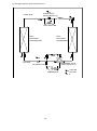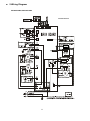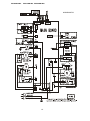
1
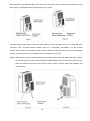
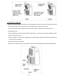
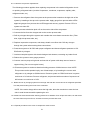
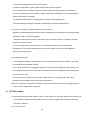
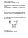
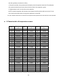
SERVICE MANUAL AIR CONDITIONER Electrolux Home Products Italy S.p.A. Corso Lino Zanussi, 30 I - 33080 Porcia – PN Fax: + 39 0434 394096 Publication number 599 76 28-75 EN Edition: 01-2013 Rev 0.0 Air conditioner Portable MODEL: EXP09CN1W EXP09HN1W EXP12HL1W CONTENTS 1. Precaution ............................................................................................................................................. 1 1.1 Safety Precaution. .............................................................................................................................. 1 1.2 Warning ............................................................................................................................................... 1 2. Function and control panel ................................................................................................................. 5 2.1 Function .............................................................................................................................................. 5 2.2 Control panel ...................................................................................................................................... 5 3. Dimension ............................................................................................................................................. 8 4 Refrigerant Cycle Diagram ................................................................................................................... 9 5 Wiring Diagram ..................................................................................................................................... 11 6 Electronic function.............................................................................................................................. 13 6.1 Terms and definitions ...................................................................................................................... 13 6.2 Electric Control working environment ........................................................................................... 13 6.3 Protection function .......................................................................................................................... 13 6.4 Fan-only mode function requirement ............................................................................................ 13 6.5 Cooling mode function requirement .............................................................................................. 13 6.6 Drying mode ..................................................................................................................................... 14 6.7 Heating mode ................................................................................................................................... 15 6.8 Sensor malfunction.......................................................................................................................... 15 6.9 Some standard functions synopsis ............................................................................................... 16 7 Installation details ............................................................................................................................... 17 7.1 Installation instructions .................................................................................................................. 17 7.2 Care and maintenance ..................................................................................................................... 26 8 Basic test procedure........................................................................................................................... 28 8.1 Defective compressor ..................................................................................................................... 28 8.2 Sealed refrigeration system repairs ............................................................................................... 30 8.3 Fan motor .......................................................................................................................................... 32 8.4 Capacitor ........................................................................................................................................... 33 9 Characteristic of temperature sensor ............................................................................................... 34 10 Troubleshooting ................................................................................................................................ 35 1. Precaution 1.1 Safety Precaution. To prevent injury to the user or other people and property damage, the following instructions must be followed. Incorrect operation due to ignoring instruction will cause harm or damage. Before service unit, be sure to read this service manual at first. 1.2 Warning Installation Do not use a defective or underrated circuit breaker. Use this appliance on a dedicated circuit. There is risk of fire or electric shock. For electrical work, contact the dealer, seller, a qualified electrician, or an Authorized service center. Do not disassemble or repair the product, there is risk of fire or electric shock. Always ground the product. There is risk of fire or electric shock. Install the panel and the cover of control box securely. There is risk of fire of electric shock. Always install a dedicated circuit and breaker. Improper wiring or installation may cause fore or electric shock. Use the correctly rated breaker of fuse. There is risk of fire or electric shock. Do not modify or extend the power cable. There is risk of fire or electric shock. Do not install, remove, or reinstall the unit by yourself(customer). There is risk of fire, electric shock, explosion, or injury. Be caution when unpacking and installing the product. Sharp edges could cause injury, be especially careful of the case edges and the fins on the condenser and evaporator. For installation, always contact the dealer or an Authorized service center. There is risk of fire, electric shock, explosion, or injury. Do not install the product on a defective installation stand. 1 It may cause injury, accident, or damage to the product. Be sure the installation area does not deteriorate with age. If the base collapses, the air conditioner could fall with it, causing property damage, product failure, and personal injury. Do not let the air conditioner run for a long time when the humidity is very high and a door or a window is left open. Moisture may condense and wet or damage furniture. Take care to ensure that power cable could not be pulled out or damaged during operation. There is risk of fire or electric shock. Do not place anything on the power cable. There is risk of fire or electric shock. Do not plug or unplug the power supply plug during operation. There is risk of fire or electric shock. Do not touch (operation) the product with wet hands. There is risk of fire or electric shock. Do not place a heater or other appliance near the power cable. There is risk of fire and electric shock. Do not allow water to run into electric parts. It may cause fire, failure of the product, or electric shock. Do not store or use flammable gas or combustible near the product. There is risk of fire or failure of product. Do not use the product in a tightly closed space for a long time. Oxygen deficiency could occur. When flammable gas leaks, turn off the gas and open a window for ventilation before turn the product on. Do not use the telephone or turn switches on or off. There is risk of explosion or fire. If strange sounds, or small or smoke comes from product. Turn the breaker off or disconnect the power supply cable. There is risk of electric shock or fire. Stop operation and close the window in storm or hurricane. If possible, remove the product from the window before the hurricane arrives. There is risk of property damage, failure of product, or electric shock. Do not open the inlet grill of the product during operation. (Do not touch the electrostatic filter, if the 2 unit is so equipped.) There is risk of physical injury, electric shock, or product failure. When the product is soaked (flooded or submerged), contact an Authorized service center. There is risk of fire or electric shock. Be caution that water could not enter the product. There is risk of fire, electric shock, or product damage. Ventilate the product from time to time when operating it together with a stove, etc. There is risk of fire or electric shock. Turn the main power off when cleaning or maintaining the product. There is risk of electric shock. When the product is not be used for a long time, disconnect the power supply plug or turn off the breaker. There is risk of product damage or failure, or unintended operation. Take care to ensure that nobody could step on or fall onto the outdoor unit. This could result in personal injury and product damage. CAUTION. Always check for gas (refrigerant) leakage after installation or repair of product. Low refrigerant levels may cause failure of product. Install the drain hose to ensure that water is drained away properly. A bad connection may cause water leakage. Keep level even when installing the product. To avoid vibration of water leakage Do not install the product where the noise or hot air from the outdoor unit could damage the neighborhoods. It may cause a problem for your neighbors. Use two or more people to lift and transport the product. Avoid personal injury. Do not install the product where it will be exposed to sea wind (salt spray) directly. It may cause corrosion on the product. Corrosion, particularly on the condenser and evaporator fins, could cause product malfunction or inefficient operation. 3 Operational. Do not expose the skin directly to cool air for long periods of time. (Do not sit in the draft). This could harm to your health. Do not use the product for special purposes, such as preserving foods, works of art, etc. It is a consumer air conditioner, not a precision refrigerant system There is risk of damage or loss of property. Do not block the inlet or outlet of air flow. It may cause product failure. Use a soft cloth to clean. Do not use harsh detergents, solvents, etc. There is risk of fire, electric shock, or damage to the plastic parts of the product. Do not touch the metal parts of the product when removing the air filter. They are very sharp. There is risk of personal injury. Do not step on pr put anything on the product. (outdoor units) There is risk of personal injury and failure of product. Always insert the filter securely. Clean the filter every two weeks or more often if necessary. A dirty filter reduces the efficiency of the air conditioner and could cause product malfunction or damage. Do not insert hands or other object through air inlet or outlet while the product is operated. There are sharp and moving parts that could cause personal injury. Do not drink the water drained from the product. It is not sanitary could cause serious health issues. Use a firm stool or ladder when cleaning or maintaining the product. Be careful and avoid personal injury. Replace the all batteries in the remote control with new ones of the same type. Do not mix old and new batteries or different types of batteries. There is risk of fire or explosion. Do not recharge or disassemble the batteries. Do not dispose of batteries in a fire. They may burn of explode. If the liquid from the batteries gets onto your skin or clothes, wash it well with clean water. Do not use the remote of the batteries have leaked. The chemical in batteries could cause burns or other health hazards 4 2. Function and control panel 2.1 Function ※ Operation mode: Cooling, Heating, Dry, Fan and Auto. ※ ION (optional) ※ Auto swing function. ※ Timer function. ※ Flexible installation kit. ※ No bucket design. ※ LED display. ※ Sleep mode. ※ Follow me function.(Optional) ※ Washable filter. ※ Self-diagnosis and auto-protection function. ※ Anti-freezing control in cooling or drying mode. Prevent the water being freezed on evaporator by sensing the evaporator pipe temperature in cooling or drying mode. ※ Auto-restart. When the power supply is interrupted and then restore, the air conditioners automatically restore the previous function setting. ※ Time Delay Safety. Restarting is for approx. 3 minutes. 2.2 Control panel EXP09CN1W2, EXP09HN1WI, EXP12HN1WI EXP09HN1W5 EXP09CN1W5 5 (1) POWER button Power switch on/off (2) SLEEP button Used to initiate the SLEEP operation. (3) FAN/ION button (ION is optional) Control the fan speed. Press to select the fan speed in four steps-LOW, MED, HI and AUTO. The fan speed indicator light illuminates under different fan settings except AUTO speed. When select AUTO fan speed, all the fan indicator lights turn dark. NOTE: Press this button for 3 seconds to initiate ION feature. The ion generator is energized and will help to remove pollen and impurities from the air, and trap them in the filter. Press it for 3 seconds again to stop the ION feature. (4) UP (+) and DOWN (-) button Used to adjust (increasing/decreasing) temperature settings (1 C/2 F increments) in a range of 17 C(62 F) to 30 C(88 F) or the TIMER setting in a range of 0~24hrs. NOTE: The control is capable of displaying temperature in degrees Fahrenheit or degrees Celsius. To convert from one to the other, press and hold the Up and Down buttons at the same time, for 3 seconds. (5) MODE select button Select the appropriate operating mode. Each time you press the button, a mode is selected in a sequence that goes from AUTO, COOL, DRY, FAN and HEAT (cooling only models without). The mode indicator light illuminates under the different mode settings. 6 (6) Timer button Used to initiate the AUTO ON start time and AUTO OFF stop time program, in conjuction with the (+)&(-) buttons. The timer on/off indicator light illuminates under the timer on/off settings. (7) SWING button (Applicable to the models with auto swing feature only) Use to initiate the Auto swing feature when the operation is ON, press the SWING button can stop the louver at the desired angle. (8) LED Display Show the set temperature in "℃" or "℉" and the Auto-timer settings. While on DRY and FAN modes, it shows the room temperature. Error codes: E1- Room temperature sensor error-Unplug the unit and plug it back in. If error repeats, call for service. E2- Evaporator temperature sensor error- Unplug the unit and plug it back in. If error repeats, call for service. E3- Condenser temperature sensor error- Unplug the unit and plug it back in. If error repeats, call for service E4- Display panel communication error- Unplug the unit and plug it back in. If error repeats, call for service. P1- Bottom tray is full - Connect the drain hose and drain the collected water away. If error repeats, call for service. (9) FOLLOW ME/TEMP SENSING feature(optional) NOTE: This feature can be activated from the remote control ONLY. The remote control serves as a remote thermostat allowing for the precise temperature control at its location. To activate the Follow Me/Temp Sensing feature, point the remote control towards the unit and press the Follow Me/Temp Sensing button. The remote display is actual temperature at its location. The remote control will send this signal to the air conditioner every 3 minutes interval until press the Follow Me/Temp Sensing button again. If the unit does not receive the Follow Me /Temp Sensing signal during any 7 minutes interval, the unit will beep to indicate the Follow Me/Temp Sensing mode has ended. 7 3. Dimension Unit Dimension W(mm) H(mm) D(mm) Single-hole 467 765 397 8 4 Refrigerant Cycle Diagram The figure below is a brief description of the important components and their function in what is called the refrigeration system. (1) This will help to understand the refrigeration cycle and the flow of the refrigerant in the cooling cycle. CAPILIARY TUBE LIQUID SIDE CONDENSER EVAPORATOR GAS SIDE COMPRESSOR 9 (2).This figure below is fit for Heat Pump Unit. LIQUID SIDE CHECK VALVE (Heating Model only) CAPILIARY TUBE HEAT EXCHANGE (EVAPORATOR) HEAT EXCHANGE (CONDENSER) GAS SIDE REVERSING VALVE (Heating Model only) ACCUMULATOR COOLING COMPRESSOR 10 HEATING 5 Wiring Diagram EXP09CN1W2,EXP09CN1W5 202025490744 11 EXP09HN1WI, EXP12HN1WI,EXP09HN1W5, 202025490732 12 6 Electronic function 6.1 Terms and definitions TC: Temperature of evaporator (T2). TA: Temperature of indoor ambient (T1). TS: The set temperature. TE: Temperature of condenser (T3) 6.2 Electric Control working environment Input voltage: 187~264V for 50Hz models and 97~127V for 60Hz models; 6.3 Protection function 6.3.1 The compressor functions protection with a delay of three minutes. 6.3.2 Sensor protection at open or short circuit. 6.3.3 Evaporator anti-icing protection at cooling mode. 6.4 Fan-only mode function requirement 6.4.1. The compressor and outdoor fan are OFF at Fan-only mode (except P1 protection). 6.4.2. The speed of indoor fan can be optionally chosen as High/Mid/Low. 6.4.3. The TS can’t be controlled, and the LED displays as T1. 6.4.4. The ION/TIMER functions are valid at the fan-only mode. 6.5 Cooling mode function requirement 6.5.1. The speed of indoor fan can be optionally selected as High/Mid/Low. 6.5.2. The outdoor fan will be turned on as soon as the unit being on cooling mode. The operation of outdoor fan is according to the compare of TA and TS when the water level is below to switch 1. If not, the outdoor fan doesn’t work. 6.5.3. The compressor operates as below: 13 Operation conditon Compressor on (TA-Ts)℃ +1 0 Compressor off 6.5.2.1 If TA﹥TS+1℃, the outdoor fan operates. After 15 seconds, the compressor operates. 6.5.2.2 The compressor is on, if TA≤TS, this compressor will stop. If the outdoor fan operates for 3 minutes at least, it will stop after delaying for 5 seconds. 6.5.3. When the unit is off, the compressor stops at first, and the indoor/outdoor fan will stop after delaying for 5seconds. (If it operates at heating mode, the outdoor fan will be off delaying for 30 seconds) 6.5.4. The ION/TIMER functions are valid at the cooling mode. 6.6 Drying mode 6.6.1. The unit operates at drying mode. If TA>13℃, outdoor fan turns on, and then the compressor operates after 15 seconds later. Operation conditon Compressor on TA ℃ 15 13 Compressor off 6.6.1.1 When TA<13℃, the compressor stops working. And the outdoor fan will stop delaying for 5 seconds until it operates for 3minutest. 6.6.1.2 When TA≥15℃, the outdoor fan operates, and the compressor will restart to operate after 15seconds. 6.6.2. The speed can’t be controlled at drying mode, and the indoor fan motor operates at low speed. 14 6.6.3. The ION/TIMER functions are valid at the drying mode. 6.7 Heating mode 6.7.1. The speed of indoor fan can be optionally chosen as High/Mid/Low. The compressor and outdoor fan keep on stop (except P1 protection) 6.7.2. At heating mode, the heater will operate according to the difference between TA and TS. Electric heater operates as below. Operation conditon (TA-Ts)℃ Heater off +1 0 Heater on 6.7.2.1. When TA﹤TS, the indoor fan operates firstly, and then the heater operates after 4 seconds. 6.7.2.2. If TA﹥TS+1℃, the heater stops. Then the heater turns off after 10 seconds. When the unit is off at the heating mode, the indoor fan motor stops delaying for 10 seconds 6.7.3. The ION/TIMER functions are valid at the heating mode. 6.8 Sensor malfunction LED display Stand for E2 T2 sensor malfunction E1 T1 sensor malfunction E4 Communication malfunction for display board and PCB E3 T3 sensor malfunction P1 Water full protection Malfunction display: When the malfunction happened at the same time, the priority is E4> E3> E2> E1>P1 15 6.9 Some standard functions synopsis 6.9.1. Timer function When the unit is on, press the Timer button will initiate the Auto-off stop program, the TIMER OFF indicator light illuminates. Press the UP or down button to select the desired time. Press the TIMER button again within 5 seconds, the Auto-on start program is initiated. And the TIMER ON indicator light illuminates. Press the up or down button to select the desired Auto-on start time. When the unit is off, press the Timer button to initiate the Auto-on start program, press it again within five seconds will initiate the Auto-off stop program. Press or hold the UP or DOWN button to change the Auto time by 0.5 hour increments, up to 10 hours, then at 1 hour increments up to 24 hours. The control will count down the time remaining until start. The system will automatically revert back to display the previous temper ature setting if there is no operation in a five seconds period. 6.9.2. Sleep function Press this button, the selected temperature will increase (cooling) or decrease (heating) by 1℃/2 ℉30 minutes. The temperature will then increase (cooling) or decrease (heating) by another 1℃/2℉ after an additional 30 minutes. This new temperature will be maintained for 7 hours before it returns to the originally selected temperature. This ends the Sleep mode and the unit will continue to operate as originally programmed. 16 7 Installation details 7.1 Installation instructions Location The air conditioner should be placed on a firm foundation to minimize noise and vibration. For safe and secure positioning, place the unit on a smooth, level floor strong enough to support the unit. The unit has casters to aid placement, but it should only be rolled on smooth, flat surfaces. Use caution when rolling on carpet surfaces. Do not attempt to roll the unit over objects. The unit must be placed within reach of a properly rated grounded socket. Never place any obstacles around the air inlet or outlet of the unit. Allow 30cm to 100cm of space from the wall for efficient air-conditioning. Window slider kit Installation Your window slider kit has been designed to fit most standard "Vertical" and "horizontal" window applications. However, it may be necessary for you to improvise/modify some aspects of the installation procedures for certain types of window. Please refer to Fig. 2 & Fig.3 for minimum and maximum window openings. Window slider kit can be fixed with a bolt (see Fig.3a). 17 Note: If the window opening is less than the mentioned minimum length of the window slider kit, cut that one with a hole in it short to fit for the window opening. Do never cut out the hole in window slider kit. 18 A a B b Type I 67.5 2.22 123 4.04 Type II 56.2 1.84 98.2 3.22 Installation in a double-hung sash window 1. Cut the foam seal (adhesive type) to the proper length and attach it to the window stool. Fig.4 2. Attach the window slider kit to the window stool. Adjust the length of the window slider kit according to the width of window, shorten the adjustable window kit if the width of window is less than 26.5 (Type I) or 22.1 (Type II) inches Open the window sash and place the window slider kit on the window stool. Fig.5 19 C Type I 26.5"~48.0" Type II 22.1"~38.6" 3. Cut the foam seal (adhesive type) to the proper length and attach it on the top of the window. Show as in Fig.6 4. Close the window sash securely against the window. 5. Cut the foam seal to an appropriate length and sealing the open gap between the top window sash and outer window sash. Show as in Fig.7 Installation in a sliding sash window 1. Cut the foam seal (adhesive type) to the proper length and attach it to the window frame. See Fig.8. 20 2. Attach the window slider kit to the window stool. Adjust the length of the window slider kit according to the width of window. Short the adjustable window kit if the width of window is less than 26.5(Type I) or 22.1(Type II) inches. Open the window sash and place the window slider kit on the window stool. See Fig.9 3. Cut the foam seal (adhesive type) to the proper length and attach it on the top of the window. Show as in Fig.10. 21 4. Close the sliding sash securely against the window. 5. Cut the foam seal to an appropriate length and sealing the open gap between the top window sash and outer window sash. Show as in Fig.11. Exhaust hose installation The exhaust hose and adaptor must be installed or removed in accordance with the usage mode. Cool, Heat(heat pump type) or Auto mode Install Fan, dehumidify or heat(electrical heat type) mode Remove 1. Install the window Exhaust adaptor B onto the exhaust hose as shown in Fig.12 or Fig.13. Refer to the 22 previous pages for window kit installation. 2. Insert the hook of the Exhaust hose into the hole seat of the air outlet and slide down the Exhaust hose along the arrow direction for installation (See Fig.14) The exhaust hose can be installed into the wall (Not applicable to the units without adaptor A, expansion plugs and wooden screws of Accessories). 1. Prepare a hole in the wall. Install the wall Exhaust adaptor A onto the wall (outside) by using 4 expansion plugs and wooden screws, be sure to fix thoroughly. (See Fig.15) 2. Attach the Exhaust hose to wall Exhaust adaptor A. 23 Note: Cover the hole using the adaptor cap when not in use. The duct can be compressed or extended moderately according to the installation requirement, but it is desirable to keep the duct length to a minimum. IMPORTANT: DO NOT OVER BEND THE DUCT (SEE Fig.16) Water drainage -During dehumidifying modes, remove the drain plug from the back of the unit, install the drain connector(5/8〞universal female mender) with 3 /4〞hose(locally purchased). For the models without 24 drain connector, just attach the drain hose to the hole. Place the open end of the hose directly over the drain area in your basement floor. Please refer to Fig.17&18. -During heating pump mode, remove the lower drain plug from the back of the unit, install the drain connector (5/8 〞 universal female mender) with 3/4 〞 hose(locally purchased). For the models without drain connector, just attach the drain hose to the hole. Place the open end of the hose adaptor directly over the drain area in your basement floor. Please refer to Fig.19 NOTE: Make sure the hose is secure so there are no leaks. Direct the hose toward the drain, making sure that there are no kinks that will stop the water flowing. Place the end of the hose into the drain and make sure the end of the hose is level or down to let the water flow smoothly. Do never let it up. 25 -When the water level of the bottom tray reaches a predetermined level, the unit beeps 8 times, the digital display area shows "P1". At this time the air conditioning/dehumidification process will immediately stop. However, the fan motor will continue to operate (this is normal). Carefully move the unit to a drain location. Remove the bottom drain plug and let the water drain away (see above Fig.20). Restart the machine until the "P1" symbol disappears. If the error repeats, call for service. NOTE: Be sure to reinstall the bottom drain plug before using the unit. 7.2 Care and maintenance Important 1) Be sure to unplug the unit before cleaning or servicing. 2) Do not use gasoline, thinner or other chemicals to clean the unit. 3) Do not wash the unit directly under a tap or using a hose. It may cause electrical danger. 4) If the power cord is damaged, it should be repaired by manufacture or its agency. 1. Air filter Clean the air filter at least once every two weeks to prevent inferior fan operation because of dust. Removal This unit has two filters. Take the upper filter out along the arrow direction (see below Fig.21), and then take the filter down. Remove the lower filter by loosening the screw, taking down the air filter as shown in Fig.22 (see below). Cleaning Wash the air filter by immersing it gently in warm water (about 40℃/104℉) with a neutral detergent. Rinse the filter and dry it in a shady place. Mounting Install the upper air filter after cleaning and install the lower filter by using the screw. NOTE: The grill and the air filer are connected and can’t be separated. 2. Unit enclosure Use a lint-free cloth soaked with neutral detergent to clean the unit enclosure. Finished by dry clean clothes. 26 3. Unit idle for a long time ※Remove the rubber plug at the back of the unit and attach a hose to drain outlet. Place the open end of the hose directly over the drain area in your basement floor (See below Fig.23). ※Remove the plug from the bottom drain outlet, all the water in the bottom tray would drain out (See below Fig.23) ※Keep the appliance running on FAN mode for half a day in a warm room to dry the appliance inside and prevent mold forming. ※Stop the appliance and unplug it, wrapped the cord and bundle it with the tape. Remove the batteries from the remote controller. ※Clean the air filter and reinstall it. ※Disconnect the exhaust hose, keep it safety, and cover the window(wall) hole with the adaptor cap 27 8 Basic test procedure 8.1 Defective compressor Compressors are single phase, depending on the model unit. All compressor motors are permanent split capacitor type using only a running capacitor across the start and run terminal. All compressors are internally spring mounted and externally mounted on rubber isolators. 8.1.1 Compressor wiring test Remove compressor terminal box cover and disconnect wires from terminals. Using an ohmmeter, check continuity across the following: Terminal "C" and "S" - no continuity - Open winding - replace compressor. Terminal "C" and "R" - no continuity - Open winding - replace compressor. Terminal "R" and "S" - no continuity - Open winding - replace compressor. 8.1.2 Ground test Use an ohmmeter to set on its highest scale. Touch one lead to the compressor body (clean point of contact as a good connection is a must) and the other probe in turn to each compressor terminal (see Figure 2.) If a reading is obtained, the compressor is grounded and must be replaced. 8.1.3 Checking the compressor efficiency 28 The reason for compressor inefficiency is normally due to broken or damaged suction and/or discharge valves, reducing the ability of the compressor to pump refrigerant gas. This condition can be checked as follows: 1. Install a piercing valve on the suction and discharge or liquid process tube. 2. Attach gauges to the high and low sides of the system. 3. Start the system and run a “cooling or heating performance test.” If test shows: A. Below normal high side pressure. B. Above normal low side pressure. C. Low temperature difference across coil. The compressor valves are faulty - replace the compressor 8.1.4 Terminal overload (external) Some compressors are equipped with an external overload which is located in the compressor terminal box adjacent to the compressor body. The overload is wired in series with the common motor terminal. The overload senses both major amperage and compressor temperature. High motor temperature or amperage heats the disc causing it to open and break the circuit to the common motor terminal. Heat generated within the compressor shell is usually due to: 1. High amperage. 2. Low refrigerant charge. 3. Frequent recycling. 4. Dirty condenser. 8.1.5 Terminal overload – Test (compressor external type) 1. Remove overload. 2. Allow time for overload to reset before attempting to test. 3. Apply ohmmeter probes to terminals on overload wires. There should be continuity through the overload. 8.1.6 Terminal overload (internal) Some model compressors are equipped with an internal overload. The overload is embedded in the motor windings to sense the winding temperature and/or current draw. The overload is 29 connected in series with the common motor terminal. Should the internal temperature and/or current draw become excessive; the contacts in the overload will open, turning off the compressor? The overload will automatically reset, but may require several hours before the heat is dissipated. 8.1.7 Checking the internal overload 1. No power to unit, remove the leads from the compressor terminals. 2. Using an ohmmeter, test continuity between terminals C-S and C-R. If not continuous, the compressor overload is open and the compressor must be replaced. 8.2 Sealed refrigeration system repairs 8.2.1 Equipment require 1. Voltmeter 2. Ammeter 3. Ohmmeter 4. E.P.A. Approved Refrigerant Recovery System. 5. Vacuum Pump (capable of 200 microns or less vacuum.) 6. Acetylene Welder 7. Electronic Halogen Leak Detector (G.E. Type H-6 or equivalent.) 8. Accurate refrigerant charge measuring device such as: a. Balance Scales - 1/2 oz. accuracy b. Charging Board - 1/2 oz. accuracy 9. High Pressure Gauge - (0 - 400 lbs.) 10. Low Pressure Gauge - (30 - 150 lbs.) 11. Vacuum Gauge - (0 - 1000 microns) 8.2.2 Equipment must be capable of: 1. Recovery CFC's as low as 5%. 2. Evacuation from both the high side and low side of the system simultaneously. 3. Introducing refrigerant charge into high side of the system. 4. Accurately weighing the refrigerant charge actually introduced into the system. 5. Facilities for flowing nitrogen through refrigeration tubing during all brazing processes. 30 8.2.3 Hermetic compressor replacement. The following procedure applies when replacing components in the sealed refrigeration circuit or repairing refrigerant leaks. (Include Compressor, condenser, evaporator, capillary tube, refrigerant leaks, etc.) 1. Recover the refrigerant from the system at the process tube located on the high side of the system by installing a line tap on the process tube. Apply gauge from process tube to EPA approved gauges from process tube to EPA approved recovery system. Recover CFCs in system to at least 5%. 2. Cut the process tube below pinch off on the suction side of the compressor. 3. Connect the line from the nitrogen tank to the suction process tube. 4. Drift dry nitrogen through the system and unsolder the more distant connection first. (Filter drier, high side process tube, etc.) 5. Replace inoperative component, and always install a new filter drier. Drift dry nitrogen through the system when making these connections. 6. Pressurize system to 30 PSIG with proper refrigerant and boost refrigerant pressure to 150 PSIG with dry nitrogen. 7. Leak test complete system with electric halogen leak detector, correcting any leaks found. 8. Reduce the system to zero gauge pressure. 9. Connect vacuum pump to high side and low side of system with deep vacuum hoses or copper tubing. (Do not use regular hoses.) 10. Evacuate system to maximum absolute holding pressure of 200 microns or less. NOTE: This process can be speeded up by use of heat lamps, or by breaking the vacuum with refrigerant or dry nitrogen at 5,000 microns. Pressure system to 5 PSIG and leave in system a minimum of 10 minutes. Recover refrigerant, and proceed with evacuation of a pressure of 200 microns or a minimum of 10%. 11. Break vacuum by charging system from the high side with the correct amount of refrigerant specified. This will prevent boiling the oil out of the crankcase. NOTE: If the entire charge will not enter the high side, allow the remainder to enter the low side in small increments while operating the unit. 12. Restart unit several times after allowing pressures to stabilize. Pinch off process tubes, cut and solder the ends. Remove pinch off tool, and leak check the process tube ends 8.2.4 Special procedure in the case of compressor motor burnout 31 1. Recover all refrigerant and oil from the system. 2. Remove compressor, capillary tube and filter drier from the system. 3. Flush evaporator condenser and all connecting tubing with dry nitrogen or equivalent, to remove all contamination from system. Inspect suction and discharge line for carbon deposits. Remove and clean if necessary. 4. Reassemble the system, including new drier strainer and capillary tube. 5. Proceed with processing as outlined under hermetic component replacement. 8.2.5 Rotary compressor special troubleshooting and service Basically, troubleshooting and servicing rotary compressors is the same as on the reciprocating compressor with only a few exceptions. 1. Because of the spinning motion of the rotary, the mounts are critical. If vibration is present, check the mounts carefully. 2. The electrical terminals on the rotary are in a different order than the reciprocating compressors. The terminal markings are on the cover gasket. Use your wiring diagram to insure correct connections. 8.2.6 Refrigerant charge 1. The refrigerant charge is extremely critical. It must be measured charge carefully - as exact as possible to the nameplate charge. 2. The correct method for charging the rotary is to introduce liquid refrigerant into the high side of the system with the unit off. Then start compressor and enter the balance of the charge, gas only, into the low side. The introduction of liquid into the low side, without the use of a capillary tube, will cause damage to the discharge valve of the rotary compressor. NOTE: All inoperative compressors returned to Friedrich must have all lines properly plugged with the plugs from the replacement compressor. 8.3 Fan motor A single phase permanent split capacitor motor is used to drive the evaporator blower and condenser fan. A self-resetting overload is located inside the motor to protect against high temperature and high amperage conditions. 8.3.1 Fan motor test 32 1. Determine that capacitor is serviceable. 2. Disconnect fan motor wires from fan speed switch or system switch. 3. Apply "live" test cord probes on black wire and common terminal of capacitor. Motor should run at high speed. 4. Apply "live" test cord probes on red wire and common terminal of capacitor. Motor should run at low speed. 5. Apply "live" test cord probes on each of the remaining wires from the speed switch or system switch to test intermediate speeds. 8.4 Capacitor A run capacitor is wired across the auxiliary and main winding of a single phase permanent split capacitor motor such as the compressor and fan motor. A single capacitor can be used for each motor or a dual rated capacitor can be used for both. The capacitor's primary function is to reduce the line current while greatly improving the torque characteristics of a motor. The capacitor also reduces the line current to the motor by improving the power factor of the load. Run capacitor hook-up line side of the capacitor is marked with a red dot and is wired to the line side of the circuit Capacitor test: 1. Remove capacitor from unit. 2. Check for visual damage such as bulges, cracks, or leaks 3. For dual rated, apply an ohmmeter lead to common (C) terminal and the other probe to the compressor (HERM) terminal. A satisfactory capacitor will cause a deflection on the pointer, 33 and then gradually move back to infinity. 4. Reverse the leads of the probe and momentarily touch the capacitor terminals. The deflection of the pointer should be two times that of the first check if the capacitor is good. 5. Repeat steps 3 and 4 to check fan motor capacitor. NOTE: A shorted capacitor will indicate a low resistance and the pointer will move to the "0" end of the scale and remain there as long as the probes are connected. An open capacitor will show no movement of the pointer when placed across the terminals of the capacitor 9 Characteristic of temperature sensor Temp.℃ Resistance KΩ Temp.℃ Resistance KΩ Temp.℃ Resistance KΩ -10 62.2756 17 14.6181 44 4.3874 -9 58.7079 18 13.918 45 4.2126 -8 56.3694 19 13.2631 46 4.0459 -7 52.2438 20 12.6431 47 3.8867 -6 49.3161 21 12.0561 48 3.7348 -5 46.5725 22 11.5 49 3.5896 -4 44 23 10.9731 50 3.451 -3 41.5878 24 10.4736 51 3.3185 -2 39.8239 25 10 52 3.1918 -1 37.1988 26 9.5507 53 3.0707 0 35.2024 27 9.1245 54 2.959 1 33.3269 28 8.7198 55 2.8442 2 31.5635 29 8.3357 56 2.7382 3 29.9058 30 7.9708 57 2.6368 4 28.3459 31 7.6241 58 2.5397 5 26.8778 32 7.2946 59 2.4468 6 25.4954 33 6.9814 60 2.3577 7 24.1932 34 6.6835 61 2.2725 8 22.5662 35 6.4002 62 2.1907 9 21.8094 36 6.1306 63 2.1124 10 20.7184 37 5.8736 64 2.0373 11 19.6891 38 5.6296 65 1.9653 12 18.7177 39 5.3969 66 1.8963 13 17.8005 40 5.1752 67 1.83 14 16.9341 41 4.9639 68 1.7665 15 16.1156 42 4.7625 69 1.7055 16 15.3418 43 4.5705 70 1.6469 34 10 Troubleshooting In general, possible trouble is classified in three kinds. One is called Starting Failure which is caused from an electrical defect, another is ineffective Air Conditioning caused by a defect in the refrigeration circuit and improper application, and the other is called the Structure Damage. TROUBLES POSSIBLE CAUSES SUGGEST REMEDIES P1 appears in the display window Drain the water in the bottom tray. Room temperature is lower than the set temperature.(Cooling mode) Reset the temperature. The windows or doors in the room are not closed. Make sure all the windows and doors are closed. There are heat sources inside the room. Remove the heat sources if possible. Exhaust air duct is not connected or blocked. Connect the duct and make sure it can function properly. Temperature setting is too high. Decrease the set temperature. Air filter is blocked by dust. Clean the air filter. 3. Noisy or vibration The ground is not level or not flat enough. Place the unit on a flat, level ground if possible. 4. Gurgling sound The sound comes from the flowing of the refrigerant inside the air-conditioner. It is normal. 5. Power shut off at Heating mode The automatic over heat protection function. When the temperature at the air outlet exceed 70℃/158℉,the device will stop. Switch on again after the unit has cool down. 1. Unit does not Start when Pressing on/off Button 2. Not cool enough 35 PPD_121107_A(50Hz, 60Hz) 36