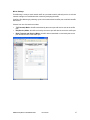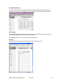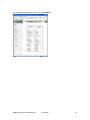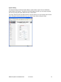
1
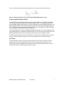
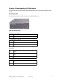
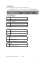
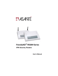
FriendlyNET® GX5-424W/448W/2400W
Smart Gigabit Ethernet Switches
User’s Manual
FriendlyNET GX5-424W/448W/2400W
Smart Gigabit Ethernet Switches
User’s Manual
Asanté Technologies, Inc.
2223 Old Oakland Road
San Jose, CA 95131
SALES
800-662-9686 Home/Office Solutions
800-303-9121 Enterprise Solutions
408-435-8388
TECHNICAL SUPPORT
801-566-8991: Worldwide
801-566-3787: Fax
www.asante.com
[email protected]
© 2004 Asanté Technologies, Inc. All rights reserved. No part of this document, or any associated artwork, product
design, or design concept may be copied or reproduced in whole or in part by any means without the express written
consent of Asanté Technologies, Inc. Asanté and FriendlyNET are registered trademarks. The Asanté logo is a trademark
of Asanté Technologies, Inc. All other brand names or product names are trademarks or registered trademarks of their
respective holders. All features and specifications are subject to change without prior notice.
Rev. A 08/04
Asanté FriendlyNET GX5-424W/448W/2400W
User’s Manual
2
Table of Contents
Chapter 1 Introduction ................................................................................................................................. 5
Features...................................................................................................................................................... 5
Chapter 2 Unpacking and Installation......................................................................................................... 6
Unpacking ................................................................................................................................................... 6
Installation................................................................................................................................................... 6
Rack Mounting ............................................................................................................................................ 6
Connecting the Network Cable ................................................................................................................... 7
AC Power.................................................................................................................................................... 7
Chapter 3 Identifying External Components .............................................................................................. 8
GX5-424W Front Panel............................................................................................................................... 8
GX5-448W Front Panel............................................................................................................................... 8
GX5-2400W Front Panel............................................................................................................................. 9
Rear Panel .................................................................................................................................................. 9
Chapter 4 Understanding LED Indicators ................................................................................................. 11
GX5-424W LEDs ...................................................................................................................................... 11
GX5-448W LEDs ...................................................................................................................................... 13
GX5-2400W LEDs .................................................................................................................................... 15
Chapter 5 GX5-W Management Utility for Windows ................................................................................ 16
Installing the GX5-W Management Utility.................................................................................................. 16
Discovery List............................................................................................................................................ 16
Monitor List ............................................................................................................................................... 17
Device Setting........................................................................................................................................... 18
Toolbar...................................................................................................................................................... 19
Chapter 6 Configuring the Switch ............................................................................................................. 20
Login ......................................................................................................................................................... 20
Setup Menu............................................................................................................................................... 21
Configuring the Setup Setting ................................................................................................................... 21
Logout ....................................................................................................................................................... 35
Support ..................................................................................................................................................... 35
Chapter 7 Technical Specifications........................................................................................................... 36
Appendix A FCC and Warranty Statements.............................................................................................. 38
FCC Compliance....................................................................................................................................... 38
FriendlyNET Warranty Statement ............................................................................................................. 38
FriendlyCare Technical Support................................................................................................................ 39
Appendix B About Gigabit Ethernet.......................................................................................................... 40
Gigabit Ethernet Technology..................................................................................................................... 40
Fast Ethernet Technology ......................................................................................................................... 40
Switching Technology ............................................................................................................................... 40
Asanté FriendlyNET GX5-424W/448W/2400W
User’s Manual
3
Virtual Local Area Network (VLAN)........................................................................................................... 41
Asanté FriendlyNET GX5-424W/448W/2400W
User’s Manual
4
Chapter 1 Introduction
Congratulations on the purchase of your FriendlyNET Smart Gigabit Ethernet switch. These
devices can switch segments running at 1000 Mbps Gigabit Ethernet, 100 Mbps Fast Ethernet,
and 10 Mbps Ethernet at full wire speeds.
The versatile GX5-W uses its on-board CPU to take the complexity out of configuring a
workgroup. Using any popular web browser, you’re only a few clicks of the mouse away from
enabling high-end services such as trunking, mirroring, virtual LANs (VLANs), and quality of
service (QoS).
Features
•
•
•
•
•
•
•
•
•
•
•
•
•
•
•
•
•
•
•
24 × 10/100 Mbps auto-negotiating Fast Ethernet RJ45 ports and 2 × SFP Mini-GBIC ports
(GX5-424W)
48 × 10/100 Mbps auto-negotiating Fast Ethernet RJ45 ports, 2 × 10/100/1000 Mbps autonegotiating Gigabit Ethernet ports, and 2 × SFP Mini-GBIC ports (GX5-448W)
24 × 10/100/1000 Mbps auto-negotiating Gigabit Ethernet ports (GX5-2400W)
Up to 4K (GX5-424W), 24K (GX5-448W), or 8K (GX5-2400W) unicast addresses entities per
device, self-learning, and table aging
768 KB (GX5-424W), 1536 KB (GX5-448W), or 400 KB (GX5-2400W) packet buffer
All RJ45 ports support Auto-Uplink™ (MDI/MDIX) for simplified wiring without crossover
cables or an uplink ports
IEEE Auto Negotiation sets full/half duplex transfer mode for 10/100 Mbps ports
Full duplex transfer mode for Gigabit ports
Wire-speed reception and transmission
Store-and-forward switching scheme capability to support rate adaptation and ensure data
integrity
Supports IEEE 802.3x flow control for full duplex mode ports
Back pressure flow control for half duplex
Supports port-based VLAN and QoS
Supports trunking on Gigabit ports
Supports port mirroring for simplified troubleshooting
Supports port-settings for speed/disable and flow control
Easy configuration via web browser
Easy setting via GX5-W Management Utility
Standard 19" rackmount size with included kit
Asanté FriendlyNET GX5-424W/448W/2400W
User’s Manual
5
Chapter 2 Unpacking and Installation
This chapter provides unpacking and installation information for the GX5-424W/448W/2400W
switch.
Unpacking
Open the shipping cartons of the GX5-W switch and carefully unpack its contents. The carton
should contain the following items:
•
•
•
•
•
•
One FriendlyNET GX5-424W, GX5-448W, or GX5-2400W switch
One AC power cord, suitable for your area’s electrical power connections
Four rubber feet to be used for desktop placement
Two rack mounting brackets with screws
CD-ROM with GX5-W Management Utility and User’s Manual
Quick Start Guide
If any item is missing or damaged, please contact your local reseller for replacement.
Installation
The site where you install the hub stack may greatly affect its performance. When installing,
consider the following pointers:
•
•
•
•
•
Install the GX5-W switch in a fairly cool and dry place. See “Technical Specifications” for the
acceptable temperature and humidity operating ranges.
Install the GX5-W switch in a site free from strong electromagnetic field generators (such as
motors), vibration, dust, and direct exposure to sunlight
Leave at least 4" of space at the front and rear of the hub for ventilation
Install the GX5-W switch on a sturdy, level surface that can support its weight, or in an EIA
standard-size equipment rack
When installing the GX5-W switch on a level surface, attach the rubber feet to the bottom of
each device. The rubber feet cushion the device and protect the case from scratching.
Rack Mounting
The switch can be mounted in an EIA standard-size, 19" rack, which can be placed in a wiring
closet with other equipment. Attach the mounting brackets at the switch’s front panel (one on
each side), and secure them with the screws provided.
Figure 1. Secure the mounting brackets with the screws provided (GX5-2400W example
used).
Asanté FriendlyNET GX5-424W/448W/2400W
User’s Manual
6
Then, use the screws provided with the equipment rack to mount each switch in the rack.
Figure 2. Mount the switch in the rack provided (GX5-2400W example used).
Connecting the Network Cable
The GX5-424W and GX5-448W switches support 10 Mbps Ethernet or 100 Mbps Fast Ethernet
and run both in half and full duplex mode using Category 5 cable. The switches also support 2
port 1000 Mbps Gigabit Ethernet that runs in auto-negotiation mode and 10 Mbps Ethernet or 100
Mbps Fast Ethernet that runs both in half and full duplex mode and 1000 Mbps Gigabit Ethernet
runs in full duplex mode using four pair of Category 5 Cable. An additional 2-port SFP Mini-GBIC
slot is included for an optional SFP Mini-GBIC module.
The GX5-2400W switch supports 1000 Mbps Gigabit Ethernet that runs in auto-negotiation mode
and 10 Mbps Ethernet or 100 Mbps Fast Ethernet that runs in half and full duplex mode and 1000
Mbps Gigabit Ethernet that runs in full duplex mode using four pair of Category 5 Cable.
The RJ45 ports support Auto-Uplink. The switches can auto-transform to MDI, so you can make
an easy connection without worrying if you are using a standard or crossover RJ45 cable.
AC Power
The GX5-W switch uses the AC power supply 100–240 VAC, 50–60 Hz. The power switch is
located at the rear of the unit adjacent to the AC power connector and the system fan. The
switch’s power supply will adjust to the local power source automatically and may be turned on
without having any or all LAN segment cables connected.
Asanté FriendlyNET GX5-424W/448W/2400W
User’s Manual
7
Chapter 3 Identifying External Components
This chapter describes the front panel, rear panel, and LED indicators of the switch.
GX5-424W Front Panel
The figure below shows the front panel of the GX5-424W switch.
Figure 3. Front panel of the FriendlyNET GX5-424W switch.
LED Indicator
Comprehensive LED indicators display the status of the switch and the network (see the following
“LED Indicators” chapter).
Fast Ethernet Ports (Ports 1-24)
These ports support network speeds of either 10 Mbps or 100 Mbps, and can operate in half and
full duplex transfer modes. These ports also supports automatic MDI/MDIX crossover detection
function and give true “plug-and-play” capability. Just plug in the network cable to the hub directly.
The end node may be a Network Interface Card (NIC), switch, or hub.
Gigabit Ethernet Ports (Ports 25–26)
The GX5-424W switch is equipped with two Gigabit twisted pair ports, supporting auto-negotiable
10/100/1000 Mbps and auto MDI/MDIX crossover detection function. These two ports can
operate in half duplex mode for 10/100 Mbps and full duplex mode for 10/100/1000 Mbps.
SFP Mini-GBIC Ports (Ports 27–28)
The GX5-424W switch is equipped with 2 SFP Mini-GBIC ports and a supporting optional
1000BaseSX/LX SFP Mini-GBIC module.
Note: When the port is set to “Forced Mode,” the Auto MDI/MDIX will be disabled.
GX5-448W Front Panel
The figure below shows the front panel of the GX5-448W switch.
Figure 4. Front panel of the FriendlyNET GX5-448W switch.
LED Indicator
Comprehensive LED indicators display the status of the switch and the network (see the following
“LED Indicators” chapter).
Fast Ethernet Ports (Ports 1-48)
These ports support network speeds of either 10 Mbps or 100 Mbps, and can operate in half and
full duplex transfer modes. These ports also supports automatic MDI/MDIX crossover detection
function and give true “plug-and-play” capability. Just plug in the network cable to the hub directly.
Asanté FriendlyNET GX5-424W/448W/2400W
User’s Manual
8
The end node may be a Network Interface Card (NIC), switch, or hub.
Gigabit Ethernet Ports (Ports 49–50)
The GX5-448W switch is equipped with two Gigabit twisted pair ports, supporting auto-negotiable
10/100/1000 Mbps and auto MDI/MDIX crossover detection function. These two ports can
operate in half duplex mode for 10/100 Mbps and full duplex mode for 10/100/1000 Mbps.
SFP Mini-GBIC Ports (Ports 51–52)
The GX5-448W switch is equipped with 2 SFP Mini-GBIC ports and a supporting optional
1000BaseSX/LX SFP Mini-GBIC module.
Note: When the port is set to “Forced Mode,” the Auto MDI/MDIX will be disabled.
GX5-2400W Front Panel
The figure below shows the front panel of the GX5-2400W switch.
Figure 5. Front panel of the FriendlyNET GX5-2400W 24-Port Gig Gigabit Ethernet Smart
switch.
LED Indicator
Comprehensive LED indicators display the status of the switch and the network (see the following
“LED Indicators” chapter).
Gigabit Ethernet Ports (Ports 1-24)
This function gives true “plug-and-play” capability. Just plug the network cable into the device
directly; it doesn’t matter if the end node is a Network Interface Card (NIC) or switch and hub.
These ports can operate in half duplex mode for 10/100 Mbps and full duplex mode for
10/100/1000 Mbps.
Note: When the port is set to “Forced Mode,” the auto-MDI/MDIX will be disabled.
Rear Panel
Figure 6. Rear panel of the GX5-W switch.
Power Switch
You can enable or disable the power with this switch.
AC Power Connector
This three-pronged connector supports the power cord. Plug in the female connector of the
provided power cord into this connector, and the male into a power outlet. Supported input
voltages range from 100–240 VAC at 50–60Hz.
Asanté FriendlyNET GX5-424W/448W/2400W
User’s Manual
9
Reset to Default
This button resets all the settings back to the factory default, including:
•
IP Address: 192.168.123.253
•
Password: admin
Note: Be sure to record the settings of your device. All of the settings will be erased when the
Reset button is pressed.
Asanté FriendlyNET GX5-424W/448W/2400W
User’s Manual
10
Chapter 4 Understanding LED Indicators
The front panel LEDs provide instant status feedback, helping to monitor and troubleshoot when
needed.
GX5-424W LEDs
The figure below shows the LED indicators on the GX5-424W switch.
Power and System LEDs
POWER: Power Indicator
On
The GX5-424W switch is receiving power.
Off
The power is off or the power cord has an improper connection.
CPU: Management Indicator
Blinking
The CPU is working or the switch is ready.
On
The CPU is not working properly; switch must be reset.
Off
The power is off or the power cord has an improper connection.
Ports 1–24 10/100 Status LEDs
Link/Activity
On
The respective port is successfully connected to an Ethernet
network.
Blinking
The port is transmitting or receiving data on the Ethernet
network.
Off
No link.
100 Mbps
On
The respective port is connected to a 100 Mbps Fast Ethernet
network.
Off
The respective port is connected to a 10 Mbps Ethernet network
Asanté FriendlyNET GX5-424W/448W/2400W
User’s Manual
11
Ports 25–26 Gigabit Status LEDs
Link/Activity
On
The respective port is successfully connected to an Ethernet
network.
Blinking
The port is transmitting or receiving data on the Ethernet
network.
Off
No link.
100 Mbps
On
The respective port is connected to a 100 Mbps Fast Ethernet
network.
Off
The respective port is connected to a 10 Mbps Ethernet or 1000
Mbps Gigabit Ethernet network.
1000 Mbps
On
The respective port is connected to a 1000 Mbps Gigabit Ethernet
network.
Off
The respective port is connected to a 10 Mbps Ethernet or 100
Mbps Fast Ethernet network.
Ports 27–28 SFP Mini-GBIC Status LEDs
Link/Activity
On
The SFP Mini-GBIC module is installed and connected to a
network.
Blinking
The SFP Mini-GBIC module is receiving data on a network.
Off
No link.
1000 Mbps
On
The respective port is connected to a 1000 Mbps Gigabit Ethernet
network.
Off
The respective port is disconnected from the network.
Asanté FriendlyNET GX5-424W/448W/2400W
User’s Manual
12
GX5-448W LEDs
The figure below shows the LED indicators on the GX5-448W switch.
Power and System LEDs
POWER: Power Indicator
On
The GX5-448W switch is receiving power.
Off
The power is off or the power cord has an improper connection.
CPU: Management Indicator
Blinking
The CPU is working or the switch is ready.
On
The CPU is not working properly; switch must be reset.
Off
The power is off or the power cord has an improper connection.
Ports 1–48 10/100 Status LEDs
Link/Activity
On
The respective port is successfully connected to an Ethernet
network.
Blinking
The port is transmitting or receiving data on the Ethernet
network.
Off
No link.
100 Mbps
On
The respective port is connected to a 100 Mbps Fast Ethernet
network.
Off
The respective port is connected to a 10 Mbps Ethernet network
Asanté FriendlyNET GX5-424W/448W/2400W
User’s Manual
13
Ports 49–50 Gigabit Status LEDs
Link/Activity
On
The respective port is successfully connected to an Ethernet
network.
Blinking
The port is transmitting or receiving data on the Ethernet
network.
Off
No link.
100 Mbps
On
The respective port is connected to a 100 Mbps Fast Ethernet
network.
Off
The respective port is connected to a 10 Mbps Ethernet or 1000
Mbps Gigabit Ethernet network.
1000 Mbps
On
The respective port is connected to a 1000 Mbps Gigabit Ethernet
network.
Off
The respective port is connected to a 10 Mbps Ethernet or 100
Mbps Fast Ethernet network.
Ports 51–52 SFP Mini-GBIC Status LEDs
Link/Activity
On
The SFP Mini-GBIC module is installed and connected to a
network.
Blinking
The SFP Mini-GBIC module is receiving data on a network.
Off
No link.
1000 Mbps
On
The respective port is connected to a 1000 Mbps Gigabit Ethernet
network.
Off
The respective port is disconnected from the network.
Asanté FriendlyNET GX5-424W/448W/2400W
User’s Manual
14
GX5-2400W LEDs
The figure below shows the LED indicators on the GX5-2400W switch.
Power and System LEDs
POWER: Power Indicator
On
The GX5-2400W switch is receiving power.
Off
The power is off or the power cord has an improper connection.
CPU: Management Indicator
Blinking
The CPU is working or the switch is ready.
On
The CPU is not working properly; switch must be reset.
Off
The power is off or the power cord has an improper connection.
Ports 1–24 Status LEDs
Link/Activity
On
The respective port is successfully connected to an Ethernet
network.
Blinking
The port is transmitting or receiving data on the Ethernet
network.
Off
No link.
1000 Mbps
On
The respective port is connected to a 1000 Mbps Gigabit Ethernet
network.
Off
The respective port is connected to a 10 Mbps Ethernet or 1000
Mbps Fast Ethernet network
100 Mbps
On
The respective port is connected to a 100 Mbps Fast Ethernet
network.
Off
The respective port is connected to a 10 Mbps Ethernet or 1000
Mbps Gigabit Ethernet network
Asanté FriendlyNET GX5-424W/448W/2400W
User’s Manual
15
Chapter 5 GX5-W Management Utility for Windows
You can configure the GX5-W switch through the Web browser. In the event you cannot
remember the switch’s IP address, this handy Windows-based utility lets you quickly discover
GX5-224W, GX5-448W, and GX5-2400W switches and lets you make simple changes
(password, firmware upgrade, traps).
For best performance, use the management screens to configure the switch before placing
it into service. Under heavy network traffic, the first priority is to handle network activity;
management screens will appear later.
Installing the GX5-W Management Utility
The following gives instructions to guide you through the installation of the GX5-W Management
Utility.
1. Insert the Utility CD in the CD-ROM drive.
2. From the Start menu on the Windows desktop, choose Run.
3. In the Run dialog box, type D:\GX5-W Management Utility\setup.exe (note that D:\ depends
on where your CD-ROM drive is located) and click OK.
4. Follow the on-screen instructions to install the utility.
5. Upon completion, go to Program Files > GX5-W_Management_Utility and execute the
program.
The Management Utility is divided into four parts: Discovery List, Monitor List, Device Setting, and
Toolbar.
Discovery List
This is the list where you can discover all the GX5-W Management devices in the entire network.
By pressing the Discovery button, you can list all the GX5-W Management devices in the
discovery list.
Asanté FriendlyNET GX5-424W/448W/2400W
User’s Manual
16
Double-click or press the Add to monitor list button to select a device from the Discovery List to
add to the Monitor List.
System word definitions in the Discovery List show:
•
•
•
•
•
•
•
•
•
MAC Address: the device MAC address
IP Address: the current IP address of the device
Protocol Version: the version of the Utility protocol
Subnet Mask: the subnet mask of the device
Gateway: the gateway of the device
Product Name: the device product name
System Name: the device system name configured
Location: configured device location
Trap IP: the IP where traps are sent
Monitor List
All of the Smart devices in the Monitor List can be monitored; you can also receive the trap and
show the status of the device.
System word definitions in the Monitor List show:
•
•
•
•
•
•
•
•
•
•
S: the system symbol of the Web-Smart device, means device is not alive or your PC’s IP
is not in the same group as your switch’s IP
IP Address: the current IP address of the device
MAC Address: the device MAC Address
Protocol Version: the version of the Utility protocol
Product Name: the device product name
System Name: the device system name configured
Location: configured device location
Trap IP: the IP where traps are to be sent
Subnet Mask: the subnet mask of the device
Gateway: the gateway of the device
Also, the View Trap function can receive the events that happen from the Smart switch in the
Monitor List.
Notice the light indicator behind the View trap button. When the light is green, no trap is
transmitted. When the light is red, a new trap is transmitted and should be viewed.
When the View trap button is clicked, a Trap Information window will appear, showing trap
information such as the Symbol, Time, Device IP, and the Event that occurred.
Asanté FriendlyNET GX5-424W/448W/2400W
User’s Manual
17
The symbol represents the trap signal; this symbol disappears after you review and click on the
event record.
Note: In order to receive trap information, the switch must be configured with Trap IP and Trap
Events in the Web browser. These are available in the Trap Setting Menu.
Add Item: To add a device to the Monitor List manually, enter the IP Address of the device that
you want to monitor.
Delete Item: To delete the device in the Monitor List.
Device Setting
You can set the device by using the function key in the Device Setting Dialog box.
Configuration Setting: In this Configuration Setting, you can set the IP Address, Subnet Mask,
Gateway, Set Trap to (Trap IP Address), System name, and Location.
Select the device in the Discovery List or Monitor List and press the appropriate button. The
Configuration Setting window will appear. After filling in the data that you want to change, you
must fill in the password and press Set to process the changed data.
Asanté FriendlyNET GX5-424W/448W/2400W
User’s Manual
18
Firmware Upgrade: Occasionally, Asanté may release new firmware for the GX5-424W, GX5448W, or GX5-2400W. To upgrade your current version, fill in the Firmware Upgrade’s dialog
boxes and press Start.
While the switch is being upgraded, make sure no traffic is in the unit, the power is not
turned off, and the Ethernet cable is not disconnected. Wait until the message “Upgrade
successful” appears before continuing with other activity. If this is not done properly, the
old firmware will be erased, but the new firmware will not be loaded—making the switch
inaccessible.
Web Access: Double-click the device in the Monitor List or select a device in the Monitor List and
press the Web Access button to access the device in Web browser.
Toolbar
The toolbar in the GX5-W Management Utility has four main tabs: File, View, Options, and Help.
The File Tab includes Monitor Save, Monitor Save As, Monitor Load, and Exit.
•
•
•
•
Monitor Save: to record the setting of the Monitor List to the default, when you open the
GX5-W Management Utility next time, it will auto-load the default recorded setting
Monitor Save As: to record the setting of the Monitor List in appointed filename and file path
Monitor Load: to manually load the setting file of the Monitor List
Exit: to exit the GX5-W Management Utility
The View TAB contains the View Log and Clear Log Functions that help you to show trap
settings.
•
•
View Log: to show the event of the GX5-W Management Utility and the device
Clear Log: to clear the log
The Option TAB contains the Refresh Time function, which helps you to refresh the time of
monitoring the device. Choose 15 secs, 30 secs, 1 min, 2 min, or 5 min to select the time of
monitoring.
The Help TAB contains the About function, which shows the version of the GX5-W Management
Utility.
Asanté FriendlyNET GX5-424W/448W/2400W
User’s Manual
19
Chapter 6 Configuring the Switch
You can use any popular web browser to configure the GX5-W switch for your network. A
network administrator can manage, control, and monitor the switch from the local LAN. This
section indicates how to configure the GX5-W switch to enable its smart functions.
Login
Before you configure this device, note that when the GX5-W switch is configured through an
Ethernet connection, the manager PC must be set on the same IP network. For example, when
the default network address of the default IP address of the switch is 192.168.123.253, the
manager PC should be set at 192.168.123.x (where x is a number between 2 and 252), and the
default subnet mask at 255.255.255.0.
Open your web browser (Internet Explorer 5, Netscape 6, Safari 1, and later). A screen resolution
of 1024x768 (or higher) is recommended.
Enter IP address http://192.168.123.253 (the factory-default IP address setting) in the address
location.
When using the GX5-W Management Utility, you do not need to remember the IP address. Select
the device shown in the Monitor List of the GX5-W Management Utility to settle the device on the
Web browser.
When the following dialog page appears, enter the default password admin and press Login to
enter the status window.
Asanté FriendlyNET GX5-424W/448W/2400W
User’s Manual
20
After entering the password, the main page comes up and the screen displays the device status.
Note: You may need to scroll down to view all the left-hand screen items, such as Logout and
Support.
Setup Menu
When the main page appears, find the Setup menu on the left side of the screen. Click on the
setup item that you want to configure.
Configuring the Setup Setting
The Setup menu contains four items: Port Settings, VLAN Settings, Trunk Settings, and Mirror
Settings.
Asanté FriendlyNET GX5-424W/448W/2400W
User’s Manual
21
Port Settings
The Port Settings menu shows each port’s status. Press the ID parameter to set each port’s
Speed, Flow Control, QoS Priority, and Link Status. When the posted information needs to be
reviewed, press the Refresh button.
The Link Status in the screen will show the connection speed and duplex mode; otherwise, this
dialog box will show Down when the port is disconnected.
Asanté FriendlyNET GX5-424W/448W/2400W
User’s Manual
22
To change the port setting, click on the ID parameter to enter the selected port to configure its
Speed/Disable, Flow Control, and QoS Setting.
Speed/Disable
This setting has six modes—100M Full, 100M Half, 10M Full, 10M Half, Auto, and Disable—for
speed or port disable selections.
Flow Control
This setting determines whether or not the GX5-W switch will handle flow control. Set FlowCtrl to
Enable for avoiding data transfer overflow. Otherwise, it sets to Disable, providing either no flow
control or other hardware/software management.
When the port is set to forced mode, the flow control will automatically set to Disable.
QoS
In some ports that need to have a high priority to manage the data transfer, QoS should be
changed. Set the port’s QoS to high to determine that the port will always transfer its data first.
Asanté FriendlyNET GX5-424W/448W/2400W
User’s Manual
23
VLAN Settings (GX5-424W and GX5-2400W Only)
Group individual ports into a small virtual network to be independent of the other ports. To add a
VLAN group, press the Add Group button. The new VLAN configuration window will appear, and
you can fill in the description in order to describe this VLAN Group. Check that the port is a
member of this VLAN Group, and press the Apply button to execute the setting.
Asanté FriendlyNET GX5-424W/448W/2400W
User’s Manual
24
After modifying the VLAN Group, check on the ID parameter. The ID VLAN configuration window
will appear.
Asanté FriendlyNET GX5-424W/448W/2400W
User’s Manual
25
Trunk Settings
The Trunk function enables cascading two devices with a double times bandwidth (up to 4000
Mbps in full duplex mode).
The only selection available for the trunk setting is port 25 and port 26. To close this function,
select disable.
The selected trunk setting port must connect to the device with the same VLAN group.
Asanté FriendlyNET GX5-424W/448W/2400W
User’s Manual
26
Mirror Settings
Port Mirroring is a way to send network traffic to a port that wouldn’t ordinarily receive it, so that a
network manager can troubleshoot the network by analyzing the traffic.
Configure Port Mirroring by selecting a port to be monitored and a sniffer port to which that traffic
will be sent.
Choose from one of these three modes:
•
•
•
TX (Transmit) Mode: all traffic transmitted by the source port will also be sent to the sniffer
port
RX (Receive) Mode: all traffic received by the source port will also be sent to the sniffer port
Both (Transmit and Receive) Mode: all traffic either transmitted or received by the source
port will also be sent to the sniffer port
Asanté FriendlyNET GX5-424W/448W/2400W
User’s Manual
27
QoS (GX5-2400W Only)
In some ports that need to have a high priority to manage the data transfer, QoS should be
changed. Set the port’s QoS to high to determine that the port will always transfer its data first.
Device Status
Click on Status to present the device status on this screen, which will show the System Status,
Port Status, VLAN Status, Trunk Status, and Mirror Status.
Press Refresh when you need to renew the posted information.
Statistics
The Statistics Menu screen will show the status of each port packet count.
Asanté FriendlyNET GX5-424W/448W/2400W
User’s Manual
28
For detailed packet information, click on the ID parameter.
Asanté FriendlyNET GX5-424W/448W/2400W
User’s Manual
29
System Setting
The System Setting includes the System Name, Location Name, Login Timeout, IP Address,
Subnet Mask, and Gateway. Through the GX5-W Management Utility, you can easily recognize
the device by using the System Name and the Location Name.
The Login Timeout is set to the idle timeout for security reasons. If no recent action has occurred
when running the Utility and the time is up, you must re-login before setting the Utility.
Asanté FriendlyNET GX5-424W/448W/2400W
User’s Manual
30
Trap Setting
Traps are messages sent by the switch to a trap receiver. Use the GX5-W Management Utility as
your trap receiver. You can configure the switch to send traps to the trap receiver for several
kinds of events. Select each of the following trap types by clicking its check box.
Trap IP
Enter the IP address of the device to which you would like to send traps.
•
System Events: monitoring the system’s trap
Device Bootup—a trap will be sent each time the device boots up
Illegal Login—if a login attempt is made with an invalid password, the system will send a trap,
and include the IP address from which the invalid attempt was made
•
Fiber Port Events: sent for signal faults on the fiber ports
Link Up/Link Down—sent each time a fiber port notes a new link or loses a previously
established link
Abnormal receive error—a trap is sent when more than 50 errors are noted within 10 seconds
Abnormal transmit error—a trap is sent when more than 50 errors are noted within 10
seconds
•
Copper Port Events: sent for signal faults on the twisted pair ports
Link Up/Link Down—sent each time a fiber port notes a new link or loses a previously
established link
Abnormal receive error—a trap is sent when more than 50 errors are noted within 10 seconds
Abnormal transmit error—a trap is sent when more than 50 errors are noted within 10
seconds
Asanté FriendlyNET GX5-424W/448W/2400W
User’s Manual
31
Set Password
Password is a valuable tool for the manager to secure the GX5-W switch. If you forget the
password, press the Reset to Default button in the rear panel of the GX5-W switch. The current
setting (including VLAN and Port Setting) will be lost and the switch will restore to the default
setting.
Asanté FriendlyNET GX5-424W/448W/2400W
User’s Manual
32
Backup Setting
The backup tools help you to back up the current setting of the switch. If you need to back up the
setting, press the Backup button to save the setting.
To restore a current setting file to the device, you must specify the backup file and press the
Restore button to proceed with the setting of the recorded file.
Note: When restoring a recorded file, the current password will not be erased.
Asanté FriendlyNET GX5-424W/448W/2400W
User’s Manual
33
Reset Setting
The Factory Reset button helps you to reset the device back to the default setting from the
factory. Be aware that the entire configuration will be reset; the IP address of the device will be
set to default setting 192.168.123.253.
Restart
Pressing the Restart button reboots the switch.
Asanté FriendlyNET GX5-424W/448W/2400W
User’s Manual
34
Logout
After pressing the Logout button, the web configuration will go back to the first Login page.
Support
Pressing the Support button takes you to the Technical Support section of Asanté’s webpage.
Asanté FriendlyNET GX5-424W/448W/2400W
User’s Manual
35
Chapter 7 Technical Specifications
Ports
Fast Ethernet:
Gigabit Ethernet:
Configuration:
Expansion:
Status Indicators
System:
Per 10/100 Port:
Per 1000 Port:
Performance
Efficiency:
Switch Fabric:
Switch Architecture:
Flow Control:
Link Aggregation:
Forwarding MAC Table:
Buffer:
Web Management
System Requirements:
Port Settings:
Port-Based VLAN:
Trunk:
Mirror:
Overview:
Port Statistics:
System:
Trap Settings:
Backup:
Reset:
24 or 48 x 10/100BaseTX Fast Ethernet ports with Auto-Uplink: RJ-45 shielded
connectors
2 x 10/100/1000BaseT Gigabit Ethernet ports with Auto-Uplink: RJ-45 shielded
connectors
2 x 1000BaseX Gigabit Ethernet ports: SPF Mini-GBIC
IEEE auto-negotiation (sets 10/100/1000 Mbps speed and half/full duplex) or
manual configuration via web management
Uplink using Gigabit Ethernet ports. Selectable trunking for 4000 Mbps aggregate
bandwidth using 1000BaseT ports
Power
Link (solid)/activity (blink) and 100 Mbps
Link (solid)/activity (blink), 1000 Mbps and 100 Mbps (1000BaseT only)
Wire-speed Gigabit Ethernet switch
12.8 Gbps aggregate (GX5-424W)
33.6 Gbps aggregate (GX5-448W)
28 Gbps aggregate (GX5-2400W)
Store-forward and integrated broadcast storm filtering
IEEE 802.3x flow control (full duplex) and back pressure (half-duplex)
1 trunk/2 ports
4000 addresses with automatic learning and aging
1152 KB total (GX5-424W)
1536 KB total (GX5-448W)
400 KB (GX5-2400W)
Internet Explorer 5, Netscape 6, Apple Safari 1, and later. Windows
98/Me/2000/NT/XP and Mac OS X
Speed (disable, auto, 10 or 100 Mbps, full or half-duplex), flow control, QoS (normal
or high)
Add or delete group, select members
Aggregate 1000BaseT ports into 1 trunk (4000 Mbps bandwidth, full duplex)
Sniffer mode (receive, transmit or both), port and source port(s)
Transmit (OK and error) and receive (OK and error),
Transmit (bytes, unicast, multicast, broadcast, drop, pause, deferred, late collision,
collision, excessive collision), receive (bytes, unicast, multicast, broadcast,
undersize, jabber, FCS error, drop, pause, excess size, oversize, fragment, SA
change, count by size)
Name, location, timeout, IP address, subnet mask and gateway
IP of monitoring station running GX5-W Management utility, system events, SFP
and 1000BaseT port events
Save/restore configuration and upgrade firmware
Reset to factory defaults and reboot switch
Asanté FriendlyNET GX5-424W/448W/2400W
User’s Manual
36
GX5-W Management Utility
System Requirements:
Supported Switches:
Discovery:
Traps:
Gigabit Port Events:
Firmware:
Settings:
Password:
Web Management:
Physical
Case:
Color:
Dimensions (W x D x H):
Mounting:
Operating Temperature:
Relative Humidity:
Power:
Standards Compliance
Network:
Windows 98/Me/NT and XP
FriendlyNET GX5-424W/448W/2400W
Automatic switch discovery or manually add switches. Save settings to a default file
View system (boot-up, illegal login) and Gigabit port events
Detects abnormal receive error and abnormal transmit error. Also detects link
up/down on SFP Mini-GBIC ports
Upgrade firmware
Save configuration settings
Change password
Open web browser to manage switch
Metal
Asanté Titanium Silver
15.8 x 7.8 x 1.7 inches, 44 x 20 x 4.4 cm
Desktop or rack (rackmount kit included)
32º to 104º F (0º to 40º C)
10% to 90% non-condensing
Internal universal switching, 100-240 VAC, 50/60 Hz, maximum 19-23 watts
IEEE 802.3 10BaseT
IEEE 802.3u 100BaseTX
IEEE 802.3ab 1000BaseT
IEEE 802.1p Class of Service Prioritization
IEEE 802.1Q Virtual LAN (VLAN)
Safety:
Emissions:
UL, CUL, CB (IEC 60950)
FCC Class A, CE Mark Class A, VCCI-A
Support
Technical Support:
Product Warranty:
24-hour support via web and ftp. 90 days of free telephone support
2-year product warranty covers defects in manufacturing and workmanship
Asanté FriendlyNET GX5-424W/448W/2400W
User’s Manual
37
Appendix A FCC and Warranty Statements
Please read the following for FCC rules and limits. The FriendlyNET GX5-424W/448W/2400W
FriendlyNET warranty and support information is also included in this section.
FCC Compliance
This equipment has been tested and found to comply with the specifications for a Class A digital
device, pursuant to Part 15 of the FCC Rules. Operation is subject to the following two conditions:
1. This device may not cause harmful interference, and
2. This device must accept any interference received, including interference that may cause
undesired operation.
These limits are designed to provide reasonable protection against harmful interference in a
residential installation. This equipment generates, uses, and can radiate radio frequency energy
and, if not installed and used according to the instructions, may cause harmful interference to
radio communications. However, there is no guarantee that interference will not occur in a
particular installation. If this equipment does cause harmful interference to radio or television
reception, which is found by turning the equipment off and on, the user is encouraged to try to
correct the interference by one or more of the following measures:
•
Reorient or relocate the receiving antenna
•
Increase the separation between the equipment or devices
•
Connect the equipment to an outlet other than the receiver's
•
Consult a dealer or an experienced radio/TV technician for assistance
FCC Caution: Any change or modification to the product not expressly approved by Asanté could
void the user’s authority to operate the device.
CE Mark Warning
This is a Class A product. In a domestic environment, this product may cause radio interference,
in which case the user may be required to take adequate measures.
FriendlyNET Warranty Statement
Subject to the following limitations and exclusions, Asanté warrants to the original end user
purchaser that the covered products will be free from defects in title, materials, and manufacturing
workmanship for a period of two (2) years from the date of purchase. This warranty excludes
fans, power supplies, non-integrated software, and accessories. Asanté warrants that the fans
and power supplies will be free from defects in title, materials, and manufacturing workmanship
for two years from date of purchase. Asanté warrants that non-integrated software included with
its products will be free from defects in title, materials, and workmanship for a period of 90 days
from date of purchase, and the company will support such software for the purpose for which it
was intended for a period of 90 days from the date of purchase. This warranty expressly excludes
problems arising due to compatibility with other vendors’ products, or future compatibility due to
third-party software or driver updates.
To take advantage of this warranty, you must contact Asanté for a return materials authorization
(RMA) number. The RMA number must be clearly written on the outside of the returned package.
Product must be sent to Asanté postage paid. In the event of a defect, Asanté will repair or
replace defective product or components with new, refurbished, or equivalent product or
components as deemed appropriate by Asanté. The foregoing is your sole remedy, and Asanté's
only obligation, with respect to any defect or non-conformity. Asanté makes no warranty with
respect to accessories (including but not limited to cables, brackets, and fasteners) included with
the covered product, nor to any discontinued product, i.e., product purchased more than thirty
Asanté FriendlyNET GX5-424W/448W/2400W
User’s Manual
38
days after Asanté has removed such product from its price list or discontinued shipments of such
product.
This warranty is exclusive and is limited to the original end user purchaser only. This warranty
shall not apply to secondhand products or to products that have been subjected to abuse,
misuse, abnormal electrical or environmental conditions, or any condition other than what can be
considered normal use.
ASANTÉ MAKES NO OTHER WARRANTIES, EXPRESS, IMPLIED, OR OTHERWISE,
REGARDING ASANTÉ PRODUCTS. EXCEPT TO THE EXTENT PROHIBITED BY
APPLICABLE LAW, ALL WARRANTIES OR CONDITIONS OF MERCHANTABILITY OR
FITNESS FOR A PARTICULAR PURPOSE ARE HEREBY DISCLAIMED. ASANTÉ’S LIABILITY
ARISING FROM OR RELATING TO THE PURCHASE, USE, OR INABILITY TO USE THE
PRODUCTS IS LIMITED TO A REFUND OF THE PURCHASE PRICE PAID. IN NO EVENT
WILL ASANTÉ BE LIABLE FOR INDIRECT, SPECIAL, INCIDENTAL, OR CONSEQUENTIAL
DAMAGES FOR THE BREACH OF ANY EXPRESS OR IMPLIED WARRANTY, INCLUDING
ECONOMIC LOSS, DAMAGE TO PROPERTY AND, TO THE EXTENT PERMITTED BY LAW,
DAMAGES FOR PERSONAL INJURY, HOWEVER CAUSED AND ON ANY THEORY OF
LIABILITY (INCLUDING NEGLIGENCE). THESE LIMITATIONS SHALL APPLY EVEN IF
ASANTÉ HAS BEEN ADVISED OF THE POSSIBILITY OF SUCH DAMAGES OR IF THIS
WARRANTY IS FOUND TO FAIL OF ITS ESSENTIAL PURPOSE.
Some jurisdictions do not allow the exclusion or limitation of incidental or consequential damages
or limitations on how long an implied warranty lasts, so the previous limitations or exclusions may
not apply to you. This warranty gives you specific legal rights, and you may have other rights,
which vary according to jurisdiction.
FriendlyCare Technical Support
Asanté offers a comprehensive support plan to help you get the most from your FriendlyNET
products.
On-line Support
These resources are available 24/7 via www.asante.com/support:
•
Web (including forums, support guides, and white papers)
•
TechInfo Library (knowledgebase)
•
Downloads (manuals, drivers and firmware)
Personalized Support
If you have a question about the use or configuration of an Asanté product, complete the contact
form at www.asante.com/support/contact with a detailed description of your configuration. Most
questions are answered within 1–2 business days.
Telephone support is available during business hours (Mountain Standard Time) at 801-5668991; check with your telephone company about toll charges.
Asanté FriendlyNET GX5-424W/448W/2400W
User’s Manual
39
Appendix B About Gigabit Ethernet
This appendix provides some background information about Ethernet/Fast Ethernet/Gigabit
Ethernet switching technology.
Gigabit Ethernet Technology
Gigabit Ethernet is an extension of IEEE 802.3 Ethernet. It utilizes the same packet structure,
format, and support for CSMA/CD protocol, full duplex, flow control, and management objects,
but with a tenfold increase in theoretical throughput over 100 Mbps Fast Ethernet and a
hundredfold increase over 10 Mbps Ethernet. Since it is compatible with all 10 Mbps and 100
Mbps Ethernet environments, Gigabit Ethernet provides a straightforward upgrade without
wasting a company’s existing investment in hardware, software, and trained personnel.
The increased speed and extra bandwidth offered by Gigabit Ethernet is essential to coping with
the network bottlenecks that frequently develop as computers and their busses get faster and
more users use applications that generate more traffic. Upgrading key components, such as your
backbone and servers, to Gigabit Ethernet can greatly improve network response times—as well
as significantly speed up the traffic between your subnets.
Gigabit Ethernet enables fast optical fiber connections to support video conferencing, complex
imaging, and similar data-intensive applications. Likewise, since data transfers occur 10 times
faster than Fast Ethernet, servers outfitted with Gigabit Ethernet NICs are able to perform 10
times the number of operations in the same amount of time.
In addition, the phenomenal bandwidth delivered by Gigabit Ethernet is the most cost-effective
method to take advantage of rapidly improving switching and routing internetworking
technologies. And with advances in silicon technology and digital signal processing that enable
Gigabit Ethernet to operate over unshielded twisted-pair (UTP) cabling, outfitting your network
with a powerful 1000 Mbps-capable backbone/server connection creates a flexible foundation for
the next generation of network technology products.
Fast Ethernet Technology
The growing importance of LANs and the increasing complexity of desktop computing
applications are fueling the need for high-performance networks. A number of high-speed LAN
technologies have been proposed to provide greater bandwidth and improve client/server
response times. Among them, 100BaseTX (Fast Ethernet) provides a non-disruptive, smooth
evolution from the current 10BaseT technology.
100 Mbps Fast Ethernet is a standard specified by the IEEE 802.3 LAN committee. It is an
extension of the 10 Mbps Ethernet standard with the ability to transmit and receive data at 100
Mbps, while maintaining the CSMA/CD Ethernet protocol. Since the 100 Mbps Fast Ethernet is
compatible with all other 10 Mbps Ethernet environments, it provides a straightforward upgrade
and takes advantage of the existing investment in hardware, software, and personnel training.
Switching Technology
Another approach to pushing beyond the limits of Ethernet technology is the development of
switching technology. A switch bridges Ethernet packets at the MAC address level of the Ethernet
protocol transmitting among connected Ethernet or Fast Ethernet LAN segments.
Switching is a cost-effective way of increasing the total network capacity available to users on a
local area network. A switch increases capacity and decreases network loading by dividing a local
area network into different segments that don’t compete with each other for network transmission
capacity.
Asanté FriendlyNET GX5-424W/448W/2400W
User’s Manual
40
The switch acts as a high-speed selective bridge between the individual segments. The switch,
without interfering with any other segments, automatically forwards traffic that needs to go from
one segment to another. By doing this, the total network capacity is multiplied, while still
maintaining the same network cabling and adapter cards.
Switching LAN technology is a marked improvement over the previous generation of network
bridges, which were characterized by higher latencies. Routers have also been used to segment
local area networks, but the cost of a router, setup and required maintenance make routers
relatively impractical. Today switches are an ideal solution to most kinds of local area network
congestion problems.
Virtual Local Area Network (VLAN)
A VLAN is a group of end-stations that is not constrained by physical location and can
communicate as if in a common broadcast domain. The primary utility of using VLAN is to reduce
latency and need for routers, using faster switching instead. Other VLAN utilities include:
•
•
Security: Security is increased with the reduction of opportunity in eavesdropping on a
broadcast network because data will be switched to only those confidential users within the
VLAN.
Cost Reduction: VLANs can be used to create multiple broadcast domains—thus
eliminating the need for expensive routers.
Port-based (or port-group) VLAN is the common method of implementing a VLAN, and is the one
supplied in the GX5-W switch.
Asanté FriendlyNET GX5-424W/448W/2400W
User’s Manual
41