1
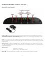
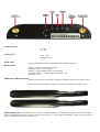
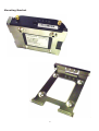
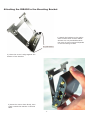
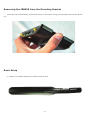
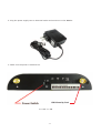
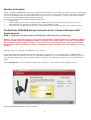
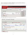
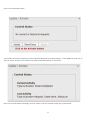
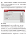
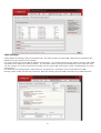
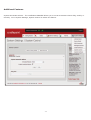
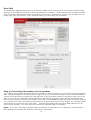
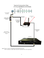
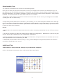
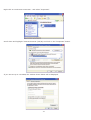
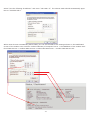
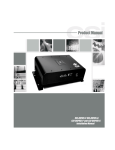
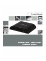
DSPMOD-CP-S/CDMA & DSPMOD-CP/CDMA
External CDMA Modem Kit
This page intentionally left blank.
-2-
Table of Contents
Product Registration Information ...................................................................................... 4
DISCLAIMER ........................................................................................................................ 4
Document Purpose / Intended Users................................................................................. 4
Application ........................................................................................................................... 4
Safety Guidelines ................................................................................................................ 4
Product Introduction .......................................................................................................... 5
CradlePoint IBR650E Hardware Overview ....................................................................... 6
Mounting Bracket ................................................................................................................ 8
Attaching the IBR650 to the Mounting Bracket ................................................................ 9
Removing the IBR650 from the Mounting Bracket ......................................................... 10
Basic Setup ........................................................................................................................ 10
Modem Activation .............................................................................................................. 12
CradlePoint IBR650E Setup Instructions for Verizon Wireless DSP Deployments ..... 12
Step 1 - Getting the modem ready for OTASP (Over the air service provisioning) ...... 12
Step 2: Activating the CradlePoint IBR650E on the Verizon Wireless Network: ........ 13
Step 3: Configuring your modem for port forwarding .................................................. 15
Port Forwarding ................................................................................................................. 15
LAN Settings ...................................................................................................................... 16
Additional Features ........................................................................................................... 17
Dual LAN ............................................................................................................................ 18
Step 4: Connecting the modem to the repeater.............................................................. 18
Functionality Test .............................................................................................................. 21
Additional Tips................................................................................................................... 21
Warranty ............................................................................................................................. 25
-3-
Product Registration Information
If applicable the ESN number may be found on the label on the bottom of the router. Note ESN
number below. If not yet activated, the ESN number will be required to do so. Retain this manual,
along with proof of purchase, to serve as a permanent record of your purchase.
MODEL NUMBER
ESN NUMBER
DATE OF PURCHASE
POINT OF SALE COMPANY
DISCLAIMER
All information and statements contained herein are accurate to the best of the knowledge of Cellular Specialties,
Inc. (CSI), but Cellular Specialties makes no warranty with respect there to, including without limitation any results
that may be obtained from the products described herein or the infringement by such products of any proprietary
rights of any persons. Use or application of such information or statements is at the users sole risk, without any
liability on the part of Cellular Specialties, Inc. Nothing herein shall be construed as licence or recommendation for
use, which infringes upon any proprietary rights of any person. Product material and specifications are subject to
change without notice. Cellular Specialties’ standard terms of sale and the specific terms of any particular sale apply.
Document Purpose / Intended Users
The purpose of this document is to provide a basic procedure to help the technician/engineer install the CSI External
Modem Kit for use with CSI’s Digital Repeaters. Following the procedures outlined will minimize risks associated with
modifying a live system and preclude service interruptions. This document assumes the technician/engineer understands the basic principles and functionality involved with repeater and in-building systems. When required, see
the Modem Activation Process Section, found later in this manual, for modem activation and activation verification.
Application
This guide should be applied whenever a need exists to activate and/or add a wireless modem capability to
Digital Repeater in an existing system or when this capability is being included with a new installation.
Safety Guidelines
The general safety information in this guideline applies to both operating and service personnel. Failure to
comply with these precautions violates safety standards of design, manufacture, and intended use of equipment. Cellular Specialties, Inc. assumes no liability for the customer’s failure to comply with these requirements:
Grounding
The External Modem Kit in conjunction with the Digital Repeater system is designed to use 110 VAC and
should always be operated with the ground wire properly connected. Do not remove or otherwise alter the
grounding lug on any power cord.
Explosive Atmospheres
To avoid explosion or fire, do not operate modem and repeater in the presence of flammable gases or fumes.
Lightning Danger
Do not install or make adjustments to the modem or repeater during an electrical storm. Use of a suitable
lightning arrester, such as CSI’s model number CSI-CAP, is very strongly recommended.
If you suspect a malfunction with this product, call your dealer or the Cellular Specialties Support Line at:
(603) 626-6677, Toll Free (USA) 1-877-844-4274.
-4-
CSI CDMA External Modem Kit for Use With Digital Repeater Installations
Warning: CSI digital repeaters, with software version 2.3.1 or higher are designed to support
the integration of the CSI CDMA External Modem Kits. Check your repeater’s Status Page for software
version and contact CSI if you need an update. See Repeater Login Section for information on how to get to
the System Status Page to verify your software version.
Adding one of the CDMA external modem kits to a CSI digital repeater installation is simple and straight
forward. The kits contain the following items:
DSPMOD-CP-S/CDMA
1.
(1) 375-1014-001 - Modem
2.
(1) 375-1013-001 - 5 port Ethernet Switch
3.
(1) 960-1047-003 - CSI Installation Manual
4.
(1) CS54-3506-47 - N Type Male to N Type Male 1’ RF jumper
5.
(1) 820-2028-001 - 3’ N Male to SMA Male Jumper
6.
(1) CS05-102-429 - 10dB Directional Coupler
7.
(1) 820-2122-014 - 14’ Ethernet Cable
8.
(2) 820-2122-001 - 7’ Ethernet Cable
DSPMOD-CP/CDMA
1.
(1) 375-1014-001 - Modem
2.
(1) 960-1047-003 - CSI Installation Manual
3.
(1) CS54-3506-47 - N Type Male to N Type Male 1’ RF jumper
4.
(1) 820-2028-001 - 3’ N Male to SMA Male Jumper
5.
(1) CS05-102-429 - 10dB Directional Coupler
6.
(1) 820-2122-014 - 14’ Ethernet Cable
Product Introduction
This document describes the CradlePoint IBR650E Setup Instructions for Verizon Wireless DSP Deployments.
Prior to Installation
Verify all the required components from the lists above are on hand prior to starting the installation process.
If you are missing parts contact Cellular Specialties, Inc. 670 N. Commercial St. Manchester NH 03101, Tel:
603-626-6677, Toll Free (USA): 877-844-4274, Fax: 603-626-6042 as soon as possible.
-5-
CradlePoint IBR650E Hardware Overview
Ports, LED’s and Switches
Power 12VDC: The power connector includes two pins for power and two pins for GPIO (General Purpose
Input/Output) functionality. The included power adapter, however, only connects to the power pins. You will
need a separate adapter for GPIO functionality.
Reset: You can return your router to factory default settings by pressing and holding the Reset button. This
button is recessed, so it requires a pointed object such as a paper clip to press. Press and hold for 10 seconds
to initiate reset.
Ethernet Ports: By default, the IBR650 has one WAN (Wide Area Network—your internet source) port and
one LAN (Local Area Network) port. Each of these ports can be reconfigured, however, if you need two LAN or
two WAN Ethernet ports.
Ethernet LED:
- Solid Green – connected
- Blinking Green – data transfer activity
Micro USB: This port can be used to to attach a direct, manual firmware upgrade if necessary.
-6-
Power On/Off:
- I = On
- O = Off
Power LED:
- Blue = On
- No light = Off
ATTN LED:
- Used with Modem LED for additional LED indications below.
Modem LED:
-
Green = On and operating normally
Blinking Green = Connecting
Amber = Not available (idle, for example)
Blinking Amber = Cellular data connection error
No light = Off
Additional LED Indications:
- Factory reset button detected = ATTN and modem LED’s blink amber twice
-Error during USB firmware upgrade = ATTN and modem LED’s blink red
Modem Antennas: The IBR650 comes with two modem antennas to enhance reception for the embedded
modem. These antennas are simple to attach and adjust. In most typical installation cases only one antenna
will be installed on the RX Diversity port.
-7-
Mounting Bracket
-8-
Attaching the IBR650 to the Mounting Bracket
1) Attach the bracket to the wall or
other surface with screws. NOTE:
Screws are not provided because
the type of screw required depends
on the mounting surface
2) Place the router‘s edge against the
bottom of the bracket.
3) Press the router down firmly, then
push it inside the bracket. It should
latch.
-9-
Removing the IBR650 from the Mounting Bracket
From the top of the bracket, press down firmly on the router using your thumb(s) and pull the device
out.
Basic Setup
1. Attach one modem antenna to the RX Diversity Port.
-10-
2. Plug the power supply into an electrical outlet and connect it to the IBR650.
3. Make sure the power is switched on.
RX Diversity Port
O = OFF I = ON
-11-
Modem Activation
NOTE: CradlePoint IBR650E modems purchased from CSI will be pre-configured; however, if your modem has
lost its configuration, you can load a configuration file or manually set up your modem. The default configuration file is included on the CD that shipped with your modem kit. Alternatively, you can request a configuration file from [email protected]
The default configuration has the following parameters:
•
DHCP is off
•
Port forwarding is set up for http (port 80), SNMP (ports 161/162) & SSH (port 22) for 2 devices
•
Both Ethernet 0 & Ethernet 1 should be set to Local Network (LAN).
•
Routing mode is NAT and Access Control for both the Primary & Guest LAN is set to Admin Access
CradlePoint IBR650E Setup Instructions for Verizon Wireless DSP
Deployments
Step 1 - Getting the modem ready for OTASP (Over the air service provisioning)
NOTES: Do not make any changes to the DSP Local Network, Remote Network or SNMP Configuration in the DSP interface UNLESS the DSP has already been configured for use with a CSI Remote
Monitoring Kit using a USB connection. If this is the case, log into the DSP, click on the Remote
Network tab, choose “Disabled,” click on “Change Settings” and then reboot the DSP prior to proceeding.
Manually set your computer’s IP address to 192.168.1.2.
Connect a straight through ethernet patch cable from to your laptop ethernet port to the “COMPUTERS or
LOCAL DEVICES (LAN) default” port of the CradlePoint IBR650E. If you need assistance changing your network settings, please refer to the “Additional Tips” section of the DSP user’s manual or to your OS documentation.
Go to 192.168.1.1 in your browser to launch the setup GUI. You should see the following screen:
Enter the default password, which is csi1234.
-12-
Step 2: Activating the CradlePoint IBR650E on the Verizon Wireless Network:
Click on the Internet tab, then select Connection Manager
Next, highlight “Modem: Internal EVDO and then click on Control
-13-
Click on the Activate button
The modem will now contact the Verizon Wireless Network for authentication. If the ESN has been set up
with an active account, the modem will respond activated within 3-5 minutes.
Once you see the above message, reset or power cycle the modem using the on/off switch.
-14-
Step 3: Configuring your modem for port forwarding, to support one or multiple
devices:
CradlePoint IBR650E modems purchased from CSI will be pre-configured; however, if your modem has lost its
configuration, you can load a configuration file or manually set up your modem. The default configuration file
is included on the CD that shipped with your modem kit. Alternatively, you can request a configuration file
from [email protected].
If your modem is already pre-configured, you needn’t proceed past activation unless you wish to change the
default settings.
To load a saved configuration, click on the System Settings tab and select System Software. Click “Restore
Settings, Upload from file” and point to the saved configuration file. Suggestion: If you do not already have
a configuration file, create one by visiting this screen of a pre-configured modem UI. Go to “Backup Current
Settings, Save to disk” to do so.
Port Forwarding
Even if you are only connecting a single device, port forwarding is used.
The modem’s GUI has remote port 8080 associated with it. To access the modem UI remotely, you
will enter the IP address provided by the wireless service provider, followed by “:8080.” Example:
http://166.1xx.2xx.3xx:8080/
To access each DSP/device remotely, you will enter the IP address that is assigned to the modem, followed by a colon (:) and the External Port that you assigned to that DSP. If you have access to the internet, test this before leaving the site. (For example, to access the web interface for DSP/device 1, enter
http://166.1xx.2xx.3xx:8001.)
To access a device via SSH, enter the correct corresponding port into your SSH client (preconfigured to use
8022 for device 1).
If you are connecting multiple repeaters and/or devices, it is recommended that the “External” port for each
device be as unique as possible. For example, in a two DSP setup, use 600x, 700x & 800x for DSP 1, and
610x, 710x & 810x for DSP 2. Each DSP/device will need to have a unique IP address in addition to the
unique port assignment. DSP “1” will keep the default IP address of 192.168.1.100. For each additional DSP,
visit “Local Networking” and change the IP address to 192.168.1.101, 192.168.1.102, etc. Please label each
repeater with its changed IP address to prevent local connection problems in the future. When changing or
re-configuring Port Forwarding, you must use the correct IP Address for each device. If only one or two devices are being monitored, no switch is required. Either port on the modem will work. A modem with default
port forwarding will look like the following screen.
-15-
LAN Settings
Under Network Settings, select Local Networks. On both Primary & Guest LAN, DHCP Server should be disabled to prevent misuse of the modem.
You may change the Guest LAN IP Address at this point. The Guest LAN IP can be used to monitor other DAS
equipment on a different network/subnet. You will also need to change the IP address of the computer that
you are using if you wish to access the modem on the Guest LAN (see section under “LAN Settings” for more
information).
For Ethernet Port Configuration, both Ethernet 0 & Ethernet 1 should be set to Local Network (LAN).
Routing mode is NAT and Access Control for both the Primary & Guest LAN should be set to Admin Access.
-16-
Additional Features
System Automatic Reboot – The CradlePoint IBR650E allows you to set an automatic reboot daily, weekly or
monthly. Go to System Settings, System Control to utilize this feature.
-17-
Dual LAN
The CradlePoint IBR650E allows the use of 2 distinct LAN’s, which is useful when connecting equipment that
already has an established subnet (a fiber DAS network for example). Either Ethernet port will support either
LAN. The Guest LAN IP Address can be changed to support your requirement. Click on the checkbox next to
Guest LAN, then click on Edit. A box will open where you can change the IP address.
Step 4: Connecting the modem to the repeater
Your modem comes with a kit that includes everything you need to connect it in line with the donor antenna &
DSP. The donor cable should connect to the “Input” Port of the directional coupler, and the provided NM-NM
jumper should be used to connect the “Through” Port of the directional coupler to the donor input port on the
DSP. If your site uses separate Cellular Band & PCS band donor antennas, please ask the Wireless Service
Provider which donor to connect the modem in line with. The NM-SMAM jumper should be connected between
the “Coupled” Port of the directional coupler and one of the antenna ports on the modem (the included paddle
antenna can be connected to the other port). Connect the supplied ethernet patch cable between the modem and the repeater. (You may also use a cross-over ethernet cable if necessary).
NOTE: If you are connecting to another brand of repeater or other device (i.e. DAS gear), that devices default gateway must match the modem’s (192.168.1.1 by default).
-18-
Typical Connection Plan
For the DSPMOD-CP-S/CDMA
Donor
Coax N Male
to N Male
IN
CS05-102-429
10dB Directional
Coupler
OUT
RX Diversity
Port
RX/TX Port
(See Note)
-10dB
820-2028-001
3' N Male to
SMA Male
Jumper
CS54-3506-47
1' N Male to N Male
Jumper
375-1014-001 Modem
2 – 820-2122-001
7' Ethernet
Cable (Included)
375-1013-001
Switch
Repeaters
2 – 820-2122-001
7' Ethernet
Cable (Optional)
Note: Donor must be connected to the RX/TX port only.
Donor antenna, coax down lead and repeaters are sold separately.
-19-
820-2122-014
14' Ethernet
Cable
Typical Connection Plan
For the DSPMOD-CP/CDMA
Donor
Coax N Male
to N Male
IN
-10dB
CS05-102-429
10dB Directional
Coupler
OUT
RX Diversity
Port
RX/TX Port
(See Note)
820-2028-001
3' N Male to
SMA Male
Jumper
375-1014-001 Modem
820-2122-014
14' Ethernet
Cable
CS54-3506-47
1' N Male to N Male
Jumper
Repeater
Note: Donor must be connected to the RX/TX port only.
Donor antenna, coax down lead and repeaters are sold separately.
-20-
Functionality Test
You must be connected to the internet for the following steps.
Once you’ve made your physical connections, connect your laptop to the internet and attempt to log in to
the DSP over the air (through the modem). Remember, you will type in the IP address that Wireless Service
Provider assigned to your modem, followed by a colon and the port number that is assigned to each protocol.
Example: To access the Web UI, enter http://166.xxx.xx.xxx:8001
*Reminder* Please make sure that the Wireless Service Provider has the correct port assignment for SNMP
(usually port 161 on each device).
If required by the Wireless Service Provider in your market, you can visit the System Health screen after logging in and click on “Trigger Test Alarm” under Band 1 and/or Band 2 to verify that alarm monitoring is working. Once the Wireless Service Provider representative has confirmed receipt of the alarm, you must clear it
to stop the alarm from reporting.
NOTES:
1, Please leave this manual, the DSP manual and any other necessary materials at the site for future service
visits.
2. It may be necessary to reboot the modem and/or DSP after configuration. Please do so if you do not gain
remote access upon completion of the configuration steps above.
3. Please remember to document the User Name and Password, and provide this to the Wireless Service Provider representative who is monitoring the DSP.
4. Additional documentation can be found @: http://www.cradlepoint.com/products/machine-to-machinerouters/cor-ibr650-3g-router-no-wifi
Additional Tips
Instructions to change TCP/IP settings on your Windows computer.
Click in the Network Connections Icon in the Control Panel. See below.
-21-
Right click on Local Area Connection - and select “Properties”.
Scroll down and highlight “Internet Protocol (TCP/IP) and click on the “Properties” button.
If you are set up to use DHCP, the window shown below will be displayed.
-22-
Select “Use the following IP address:” and enter “192.168.1.2.” The subnet mask should automatically populate to “255.255.255.0.
While most devices automatically detect DNS, you can set the DNS to the settings shown on the Dashboard
screen of the modem user interface. Default Gateway of computer has to = the IPAddress of the modem Preffered DNS servers = modem DNS Servers #1 Alternate DNS server = modem DNS Servers #2.
-23-
Nothing else will need to be chosen or entered. Click “OK”, then “OK” again and retry connection.
A crossover Ethernet cable (supplied) must be used for Web Interface access. As a reminder, you must verify
the Ethernet port on your laptop is powered. If your laptop is on battery power, the Ethernet port may be
inactive by default. If this is the case simply plug in the laptop to a 110vac source or change the power settings to enable the Ethernet port when the laptop is using battery power.
Index
A
Modem Activation 12
Modem Antennas 7
Modem LED 7
Mounting Bracket 8
Activating the CradlePoint IBR650E on the Verizon
Wireless Network 13
Additional Features 17
Additional LED Indications 7
Additional Tips 21
Application 4
Attaching the IBR650 to the Mounting Bracket 9
ATTN LED 7
P
Port Forwarding 15
Ports, LED’s and Switches 6
Power 6
Power LED 7
Power On/Off 7
Product Introduction 5
Product Registration Information 4
B
Basic Setup 10
C
R
Configuring your modem for port forwarding 15
D
Removing the IBR650 from the Mounting Bracket 10
Reset 6
Document Purpose 4
Dual LAN 18
S
E
Safety Guidelines 4
Step 4: Connecting the modem to the repeater 18
Ethernet LED 6
Ethernet Ports 6
W
Warranty 25
F
Functionality Test 21
G
Getting the modem ready for OTASP 12
H
Hardware Overview 6
I
Intended Users 4
L
LAN Settings 16
M
Micro USB 6
-24-
Warranty
This is a one year limited warranty. Seller warrants that its products are transferred rightfully and with good title; that its products are free from any lawful security interest or other lien or
encumbrance unknown to Buyer; and that for a period of one
year from the date of installation or fifteen months from the date
of original shipment, whichever period expires first, such products will be free from defects in material and workmanship which
arise under proper and normal use and service. Buyer’s exclusive remedy hereunder is limited to Seller’s correction (either at
its plant or at such other place as may be agreed upon between
Seller and Buyer) of such defects by repair or replacement at no
cost to Buyer. Transportation costs in connection with the return of products to Seller’s plant or designated facility shall be
paid by Buyer. The provisions of this warranty shall be applicable
with respect to any product which Seller replaces pursuant to it.
SELLER MAKES NO WARRANTY, EXPRESS OR IMPLIED, OTHER
THAN AS SPECIFICALLY STATED ABOVE. EXPRESSLY EXCLUDED
ARE THE IMPLIED WARRANTIES OF MERCHANTABILITY AND FITNESS FOR PURPOSE. THE FOREGOING SHALL CONSTITUTE ALL
OF SELLER’S LIABILITY (EXCEPT AS TO PATENT INFRINGEMENT)
WITH RESPECT TO THE PRODUCTS. IN NO EVENT SHALL SELLER
BE LIABLE FOR SPECIAL, CONSEQUENTIAL OR INCIDENTAL DAMAGES, INSTALLATION COSTS, LOST REVENUE OR PROFITS, OR
ANY OTHER COSTS OF ANY NATURE AS A RESULT OF THE USE
OF PRODUCTS MANUFACTURED BY THE SELLER, WHETHER USED
IN ACCORDANCE WITH INSTRUCTIONS OR NOT. UNDER NO
CIRCUMSTANCES SHALL SELLER’S LIABILITY TO BUYER EXCEED
THE ACTUAL SALES PRICE OF THE PRODUCTS PROVIDED HEREUNDER. No representative is authorized to assume for Seller any
other liability in connection with the products.
-25-
Notes
-26-
Notes
-27-
960-1147-003 rev A ECO 2707