1
Quick Start Guide
Cisco IAD2430 Series Integrated Access Devices
INCLUDING LICENSE AND WARRANTY
1
Cisco 90-Day Limited Hardware Warranty Terms
2
Related Documentation
3
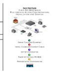
Equipment, Tools, and Accessories
4
Product Serial Number Location
5
Installing the Chassis
6
Installing a WAN or Voice Interface Card
7
Connecting Cables
8
Powering On the Cisco IAD
9
Performing the Initial Configuration
10 Obtaining Documentation
11 Documentation Feedback
12 Cisco Product Security Overview
13 Obtaining Technical Assistance
14 Obtaining Additional Publications and Information
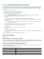
1 Cisco 90-Day Limited Hardware Warranty Terms
There are special terms applicable to your hardware warranty and various services that you can use during the warranty period.
Your formal Warranty Statement, including the warranties and license agreements applicable to Cisco software, is available on
Cisco.com. Follow these steps to access and download the Cisco Information Packet and your warranty and license agreements
from Cisco.com.
1. Launch your browser, and go to this URL:
http://www.cisco.com/univercd/cc/td/doc/es_inpck/cetrans.htm
The Warranties and License Agreements page appears.
2. To read the Cisco Information Packet, follow these steps:
a. Click the Information Packet Number field, and make sure that the part number 78-5235-03A0 is highlighted.
b. Select the language in which you would like to read the document.
c. Click Go.
The Cisco Limited Warranty and Software License page from the Information Packet appears.
d. Read the document online, or click the PDF icon to download and print the document in Adobe Portable Document
Format (PDF).
Note
You must have Adobe Acrobat Reader to view and print PDF files. You can download the reader from Adobe’s
website: http://www.adobe.com
3. To read translated and localized warranty information about your product, follow these steps:
a. Enter this part number in the Warranty Document Number field:
78-5236-01C0
b. Select the language in which you would like to read the document.
c. Click Go.
The Cisco warranty page appears.
d. Review the document online, or click the PDF icon to download and print the document in Adobe Portable Document
Format (PDF).
You can also contact the Cisco service and support website for assistance:
http://www.cisco.com/en/US/support.
Duration of Hardware Warranty
Ninety (90) days.
Replacement, Repair, or Refund Policy for Hardware
Cisco or its service center will use commercially reasonable efforts to ship a replacement part within ten (10) working days after
receipt of a Return Materials Authorization (RMA) request. Actual delivery times can vary, depending on the customer location.
Cisco reserves the right to refund the purchase price as its exclusive warranty remedy.
To Receive a Return Materials Authorization (RMA) Number
Contact the company from whom you purchased the product. If you purchased the product directly from Cisco, contact your
Cisco Sales and Service Representative.
Complete the information below, and keep it for reference:
Company product purchased from
Company telephone number
Product model number
Product serial number
Maintenance contract number
2
2 Related Documentation
User Documentation
The latest information is always online. To view or print an online document in its original format, click the PDF icon.
You can also order printed copies of many documents. See the “Obtaining Documentation” section on page 23.
To find online user documentation (PDF and HTML formats):
From Cisco.com at http://www.cisco.com at the following location:
Products and Services > Voice Gateways > Cisco IAD2400 Series Integrated Access Devices
From the Cisco legacy website (Cisco Connection Online) at the following URL:
http://www.cisco.com/univercd/home/home.htm
Tip
To navigate to the next higher level in the documentation hierarchy, click CONTENTS in the navigation bar at the top
of each page.
Cisco IAD2430 Series Documentation
This Document
You can find this quick start guide at the following URL:
http://www.cisco.com/univercd/cc/td/doc/product/access/iad/iad2430/2430qsg/index.htm
or on Cisco.com at the following location:
Products and Services > Voice Gateways > Cisco IAD2400 Series Integrated Access Devices > Technical Documentation > Quick
Start > Cisco IAD2430 Series Integrated Access Devices Quick Start Guide
Regulatory Compliance and Safety Information
The regulatory compliance and safety information document provides essential safety information applicable to your
Cisco IAD. This document contains multiple-language translations of the safety warnings applicable to both Cisco IAD2420
series and Cisco IAD2430 series devices.
You can find this document at the following URL:
http://www.cisco.com/univercd/cc/td/doc/product/access/iad/2400rcsi/2400rcsi.htm
or on Cisco.com at the following location:
Products and Services > Voice Gateways > Cisco IAD2400 Series Integrated Access Devices > Cisco IAD2400 Series Regulatory
Compliance and Safety Information
Hardware Installation Guide
The hardware installation guide provides additional detailed description, installation, and cabling information.
You can find this document at the following URL:
http://www.cisco.com/univercd/cc/td/doc/product/access/iad/iad2430/hw_inst/index.htm
or on Cisco.com at the following location:
Products and Services > Voice Gateways > Cisco IAD2400 Series IADs > Technical Documentation > Cisco IAD2430 Series
Integrated Access Devices > Installation Guides Books > Cisco IAD2430 Series Hardware Installation Guide
3
Software Configuration Guide
The software configuration guide provides additional detailed configuration information specific to Cisco IAD2430 series IADs.
You can find this document at the following URL:
http://www.cisco.com/univercd/cc/td/doc/product/access/iad/iad2430/sw_conf/index.htm
or on Cisco.com at the following location:
Products and Services > Voice Gateways > Cisco IAD2400 Series IADs > Technical Documentation > Cisco IAD2430 Series
Integrated Access Devices > Configuration Guides Books > Cisco IAD2430 Series Software Configuration Guide
Release Notes
Cisco IOS release notes for Cisco IAD2430 series IADs provide up-to-date information about Cisco IOS software releases used
on Cisco IAD2430 series IADs.
You can find these documents at the following URL:
http://www.cisco.com/univercd/cc/td/doc/product/access/iad/iad2430/index.htm
Cisco IOS Software Documentation
Master Index to Software Documentation
The master index provides links to topics and commands for each Cisco IOS software release. This includes configuration
guides, command references, release notes, new feature documentation, and system messages.
You can find master indexes at the following URL:
http://www.cisco.com/univercd/cc/td/doc/product/software/index.htm
or on Cisco.com at the following location:
Products and Services > Voice Gateways > Cisco IAD2400 Series IADs > Technical Documentation > Cisco IAD2430 Series
Integrated Access Devices > Software Center
That resource is also available at the following URL:
http://www.cisco.com/public/sw-center/
If you have an account on Cisco.com, you can get updated information about platform support for features from Cisco Feature
Navigator at the following URL:
http://www.cisco.com/go.fn
3 Equipment, Tools, and Accessories
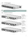
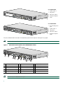
Products in the Cisco IAD2430 Series
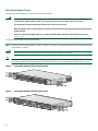
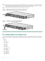
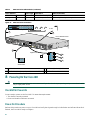
The Cisco IAD2430 series consists of five models with a common front panel (Figure 1). All models include a slot for the
external compact flash card, as well as console, auxiliary, and compact flash (CF) ports. The front panel, labeled
“Cisco IAD2400 Series,” is identical for all models. However, the back panels, labeled by specific model number, vary
considerably, depending on interfaces, ports, and options. Analog voice ports use an RJ-21 interface.
4
Figure 1
Cisco IAD2430 Series Front Panel
CISCO IAD
88839
2400
Note
The Cisco IAD2432-24FXS is used to illustrate the examples in this guide.
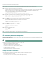
Figure 2 identifies the different back panels and features of the models.
Identifying Models in Cisco IAD2430 Series
Cisco IAD2430-24FXS
• RJ-21 analog voice
interface
• T1/E1 ports: none
• FE ports: 2
VG224-24
88838
FXS
• External compact
flash
Cisco IAD2431-8FXS
• RJ-21 analog voice
interface
• T1/E1 ports: 1
• FE ports: 1
IAD2431-8
FXS
88825
• WIC/VIC option
• External compact
flash
Cisco IAD2431-16FXS
• RJ-21 analog voice
interface
• T1/E1 ports: 1
• FE ports: 2
IAD2431-1
6FXS
• WIC/VIC option
88826
Figure 2
• External compact
flash
5
Cisco IAD2431-1T1E1
• T1/E1 ports: 2
• FE ports: 2
• WIC/VIC option
• External compact
flash
IAD2431-1
88827
T1E1
Cisco IAD2432-24FXS
• RJ-21 analog voice
port
• T1/E1 ports: 2
• FE ports: 2
88824
• WIC/VIC option
The Cisco IAD2432-24FXS is used to illustrate back-panel function options. See Figure 3 on page 6.
Note
Not all models have all functions.
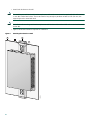
Figure 3
2
3
4
88828
1
Back-Panel Functions Options (Cisco IAD2432-24FXS shown)
6
5
7
8
9
11 12
10
13
1
Chassis ground connection
6
WIC/VIC slot
11 DC power input
2
RJ-21 connector
7
Fast Ethernet port 1
12 On/off switch
3
T1/E1 port 1
8
Fast Ethernet port 0
13 AC power input
4
T1/E1 port 0
9
AUX port
5
Compact flash port
10 Console port
Note
6
The console port is above the AUX port.
• External compact
flash
Items Included with Cisco IAD2430 Series IADs
The following are included with each model in the series:
• Rack-mount brackets for 19-inch rack; grounding lug and fasteners; power cord
• Chassis guard for wall-mounting applications
• Connected RJ-45-to-DB9 cable (labeled Console)
• Connected RJ-45-to-DB-25 cable (labeled Auxiliary)
• Cisco IAD2400 Series Regulatory Compliance and Safety Information
• Quick Start Guide—Cisco IAD2400 Series Integrated Access Devices (this document)
Note
Power cords vary, depending upon local requirements.
Items Not Included
You may need one or more items on this list for your application:
• Four telco machine screws, for installing the chassis in a rack (Use the screw size required by the rack.)
• Eight wood screws or other fasteners, for installing the chassis on a wall. An additional starter screw may be used to
facilitate wall mounting.
• PC running terminal emulation software for administrative access
• Modem for remote access
• Fast Ethernet RJ-45-to-RJ-45 straight-through cable
• T1 or E1 interface RJ-48 T1 cable
• Analog voice RJ-21 cable
• Digital voice RJ-48 T1 cable
• Serial, RJ-48, or RJ-45 cables for connecting WAN interface cards or voice interface cards
• Tools: number 2 Phillips screwdriver; medium blade screwdriver; ESD-preventive wrist strap
4 Product Serial Number Location
The serial number label for the Cisco IAD2430 series is located on the bottom of the chassis, near the compliance label. The
size of the serial number label is 0.25 x 1 inch. It has the letters “SN:” followed by eleven characters.
5 Installing the Chassis
Safety Information
Caution
For safety information you need to know before working on your Cisco IAD2430 series IAD, see the
Cisco IAD2400 Series Regulatory Compliance and Safety Information document that accompanied this product.
That document provides translations for each of the warnings.
7
IMPORTANT SAFETY INSTRUCTIONS
Warning
This warning symbol means danger. You are in a situation that could cause bodily injury. Before you work on any
equipment, be aware of the hazards involved with electrical circuitry and be familiar with standard practices for
preventing accidents. To see translations of the warnings that appear in this publication, refer to the translated
safety warnings that accompanied this device.
Note: SAVE THESE INSTRUCTIONS
Note: This documentation is to be used in conjunction with the specific product installation guide that shipped
with the product. Statement 1071
Warning
Only trained and qualified personnel should be allowed to install or replace this equipment. Statement 1030
Warning
This unit is intended for installation in restricted access areas. A restricted access area can be accessed only
through the use of a special tool, lock and key, or other means of security. Statement 1017
Warning
This equipment must be installed and maintained by service personnel as defined by AS/NZS 3260. Incorrectly
connecting this equipment to a general-purpose outlet could be hazardous. The telecommunications lines must be
disconnected 1) before unplugging the main power connector or 2) while the housing is open, or both. Statement
1043
Warning
Ultimate disposal of this product should be handled according to all national laws and regulations. Statement 1040
Warning
Blank faceplates and cover panels serve three important functions: they prevent exposure to hazardous voltages
and currents inside the chassis; they contain electromagnetic interference (EMI) that might disrupt other
equipment; and they direct the flow of cooling air through the chassis. Do not operate the system unless all cards,
faceplates, front covers, and rear covers are in place. Statement 1029
8
Chassis Installation Options
You can set the chassis on a desktop, install it in a rack, or mount it on a wall.
Tip
Before proceeding, consider the location of the equipment with respect to a good ground. See the “Grounding the
Chassis” section on page 13.
See the following instructions:
• Using the Correct Bracket Screws, page 9
• Using Quick Installation Brackets, page 9
• Rack-Mounting the Chassis, page 10
• Wall-Mounting the Chassis, page 11
• Grounding the Chassis, page 13
Caution
Use only the mounting hardware supplied with this product.
Using the Correct Bracket Screws
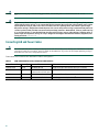
Two sets of bracket attachment screws are provided, in separate packages. Take care to use each screw type, and washers as
needed, in the appropriate locations. Table 1 summarizes the bracket attachment screw types.
Table 1
Bracket Attachment Screws for Rack-Mounting and Wall-Mounting
Rack-mounting
Wall-mounting
• Eight Phillips head screws (four per bracket)
• Four 6-32 slotted hex screws (two per bracket) and four plastic washers
• Washers are not required
• Washers are required
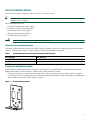
Using Quick Installation Brackets
A new bracket accompanies this product. See Figure 4. This bracket, with a keyhole feature, facilitates wall-mounting by
allowing the installer to rest the bracket on a starter screw, freeing the installer’s hands.
• To rack-mount the unit, you have three positioning options. See the “Rack-Mounting the Chassis” section on page 10.
• To wall-mount the unit, attach the short leg of the bracket to the chassis at the pair of holes in the center of the chassis side.
See the “Wall-Mounting the Chassis” section on page 11.
Quick Installation Bracket
88815
Figure 4
9
Rack-Mounting the Chassis
The following warning applies only when the unit is rack-mounted:
Warning
To prevent bodily injury when mounting or servicing this unit in a rack, you must take special precautions to
ensure that the system remains stable. The following guidelines are provided to ensure your safety:
This unit should be mounted at the bottom of the rack if it is the only unit in the rack.
When mounting this unit in a partially filled rack, load the rack from the bottom to the top with the heaviest component at the
bottom of the rack.
If the rack is provided with stabilizing devices, install the stabilizers before mounting or servicing the unit in the rack.
Statement 1006
To rack-mount the chassis, follow this procedure:
Step 1
Caution
Note
Make sure to use the correct screws for this mounting option (see Table 1 on page 9).
Screws are included for attaching the brackets to the chassis, but not for installing the chassis in a rack or on a wall.
You need four additional machine screws to install the chassis in a rack. Use the screw size required by your rack.
19-Inch Rack-Mounting with Front Panel Forward
88840
Figure 5
Choose one of the methods shown in Figure 5, Figure 6, or Figure 7, and attach the long leg of the mounting brackets
to the chassis, as shown.
CISCO IAD
2400
19-Inch Rack-Mounting with Rear Panel Forward
88841
Figure 6
10
Telco 19-Inch Rack-Mounting with Rear Panel Forward
88842
Figure 7
Step 2
Install the chassis in the rack.
Wall-Mounting the Chassis
The following warning applies only when the unit is wall-mounted:
Warning
This unit is intended to be mounted on a wall. Please read the wall mounting instructions carefully before
beginning installation. Failure to use the correct hardware or to follow the correct procedures could result in a
hazardous situation to people and damage to the system. Statement 248
Caution
You can wall-mount the unit with either the right or left side facing up; however, the front and rear panels must be
vertical.
To wall-mount the chassis, follow this procedure:
Step 1
Attach the short leg of one bracket to the chassis, as shown in Figure 8, using two 6-32 x 1/4 slotted hex screws
(provided). Be sure to use a plastic washer (provided) with each screw; the narrow end of the washer must fit into the
bracket slot, facing the chassis.
Be sure to use the correct screws and plastic washers for this mounting option. (See Table 1 on page 9.)
Figure 8
Attaching the Brackets for Wall-Mounting
88843
Caution
Step 2
Attach the second bracket to the opposite side of the chassis.
Step 3
Attach the router to the wall using the brackets previously attached and attachment hardware that you provide as
follows:
• You can install a starter screw in the wall, and hook the bracket keyhole over the screw. This holds the unit in place
for easy installation of the attachment screws.
11
• Attach both brackets to the wall.
Note
For attaching to a wall stud, each bracket requires two #10 wood screws (round- or pan-head) with #10 washers,
or two #10 washer-head screws. The screws must be long enough to penetrate at least 3/4 inch (20 mm) into
supporting wood or metal wall stud.
Note
For hollow-wall mounting, each bracket requires two wall anchors with washers. Wall anchors and washers must
be size #10.
• Figure 9 shows the orientation required for installation.
Figure 9
Attaching the Chassis to a Wall
3
1
2
103514
CISCO IAD2400 SERIES
4
12
1
Wall
3
Wall stud
2
Bracket
4
Keyhole (for starter screw)
Grounding the Chassis
Warning
This equipment must be grounded. Never defeat the ground conductor or operate the equipment in the absence of
a suitably installed ground conductor. Contact the appropriate electrical inspection authority or an electrician if
you are uncertain that suitable grounding is available. Statement 1024
Warning
Use copper conductors only. Statement 1025
Warning
AC connected units must have a permanent ground connection in addition to the power cable ground wire.
NEBS-compliant grounding satisfies this requirement. Statement 284
You must connect the chassis to a reliable earth ground; the ground wire must be installed in accordance with local electrical
safety standards.
• For NEBS-compliant grounding, use size AWG 6 (13 mm2) wire and the ground lug provided in the accessory kit.
• For NEC-compliant grounding, use size AWG 14 (2 mm2) or larger wire and an appropriate user-supplied ring terminal.
• For EN/IEC 60950-compliant grounding, use size AWG 18 (1 mm2) or larger wire and an appropriate user-supplied ring
terminal.
To connect the chassis to a reliable earth ground, perform the following steps:
Step 1
Locate a suitable ground.
Tip
Using a multimeter, measure the resistance between various possible ground locations, such as between the ground of
a junction box (outlet) and the ground of a power tap, between the ground of a junction box and a metal water pipe,
between the Cisco IAD chassis and the ground of a power tap, and between the Cisco IAD chassis and the ground of a
junction box. A good ground connection should read between 0.0 and 0.5 ohms.
Step 2
Strip one end of the ground wire to the length required for the ground lug or terminal.
• For the NEBS ground lug—approximately 0.75 in. (20 mm)
• For user-provided ring terminal—as required
Step 3
Crimp the ground wire to the ground lug or ring terminal, using a crimp tool of the appropriate size.
13
Step 4
Attach the ground lug or ring terminal to the chassis as shown in Figure 10 or Figure 11. For the ground lug, use the
two screws with captive locking washers provided. For a ring terminal, use one of the screws provided. Use a number 2
Phillips screwdriver, and tighten the screws to a torque of 8 to 10 in-lb (0.9 to 1.1 N-m).
Step 5
Connect the other end of the ground wire to a grounding point at your site.
Figure 10
NEBS-Compliant Chassis Ground Connection Using Ground Lug
88844
Ground lug
Chassis Ground Connection Using Ring Terminal
Ring terminal
attachment
103512
Figure 11
6 Installing a WAN or Voice Interface Card
The Cisco IAD2430 series IAD includes a slot for a WAN interface card (WIC) or voice interface card (VIC). The following
WICs and VICs (also used by Cisco 2600 series and Cisco 3600 series routers) are supported in releases of the Cisco IAD2430
series:
• WIC-1T
• WIC-2T
• WIC-1DSU-T1
• VIC2-2FXS
• VIC2-4FXS
• VIC2-2FXO
• VIC2-4FXO
• VIC2-2BRI-NT/TE
• WIC-1ADSL
• WIC-1SHDSL-V2
• WIC-1ADSL-DG
• VWIC-2MFT-T1
• VWIC-2MFT-E1
14
Note
Contact your Cisco account representative for the most recent supported cards.
For detailed information on installing and connecting interface cards, refer to the following:
“Installing WAN and Voice Interface Cards in Cisco Modular Routers,” in the Cisco Interface Cards Installation Guide, at the
following URL:
http://www.cisco.com/univercd/cc/td/doc/product/access/acs_mod/cis2600/hw_inst/wic_inst/wic_doc/index.htm
Caution
WAN and voice interface cards do not support online insertion and removal (hot swapping). Before inserting a card
into the Cisco IAD chassis, you must turn off electrical power and disconnect network cables.
Always use an ESD-preventive wrist strap before handling cards.
To install a WIC or VIC, follow this procedure:
Step 1
Use a number 2 Phillips screwdriver to remove the screws holding the metal plate over the card slot cover. Remove the
plate.
Step 2
Holding the interface card by the edges, line up the card with the guides on both sides of the slot.
Step 3
Insert the card in the slot. Push until it is firmly seated in the connector and the front panel of the card is flush with the
rear panel of the Cisco IAD.
Step 4
Use the screwdriver to tighten the captive screws on the card.
7 Connecting Cables
Warning
Do not work on the system, or connect or disconnect cables during periods of lightning activity. Statement 1001
Warning
Read the installation instructions before connecting the system to the power source. Statement 1004
Warning
This product relies on the building’s installation for short-circuit (overcurrent) protection. Ensure that the
protective device is rated not greater than:
120 VAC, 15A (240 VAC, 10A international) Statement 1005
Warning
To avoid electric shock, do not connect safety extra-low voltage (SELV) circuits to telephone-network voltage
(TNV) circuits. LAN ports contain SELV circuits, and WAN ports contain TNV circuits. Some LAN and WAN ports
both use RJ-45 connectors. Use caution when connecting cables. Statement 1021
Warning
Hazardous network voltages are present in WAN ports regardless of whether power to the unit is OFF or ON. To
avoid electric shock, use caution when working near WAN ports. When detaching cables, detach the end away
from the unit first. Statement 1026
Warning
This equipment has been designed for connection to TN and IT power systems. Statement 1007
15
Warning
Before performing any of the following procedures, ensure that power is removed from the DC circuit. Statement
1003
Warning
To prevent accidental discharge in the event of a power line cross, route on-premise wiring away from power
cables and off-premise wiring, or use a grounded shield to separate the on-premise wiring from the power cables
and off-premise wiring. A power line cross is an event, such as a lightning strike, that causes a power surge.
Off-premise wiring is designed to withstand power line crosses. On-premise wiring is protected from power line
crosses by a device that provides overcurrent and overvoltage protection. Nevertheless, if the on-premise wiring
is in close proximity to, or not shielded from, the off-premise wiring or power cables during a lightning strike or
power surge, the on-premise wiring can carry a dangerous discharge to the attached interface, equipment, and
nearby personnel. Statement 338
Connecting LAN and Power Cables
Caution
The Cisco IAD2430 series chassis provides inputs for both AC and DC power. Design your installation to use only
one type of power. Do not use AC and DC power at the same time. If you do, the unit stops operating, and you
must reboot it with only a single power source.
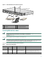
These cables and connections are described in Table 2 and Figure 12.
Table 2
LAN, Administrative Access, and Power Cable Selection
Port or Connection
Color or Type Connected To
Cable
Fast Ethernet
Yellow
Fast Ethernet hub
Straight-through Fast Ethernet cable (not included)
Console
Light blue
PC or ASCII terminal
RJ-45-to-DB9 console cable (included)
communication (COM) port
Auxiliary
Black
Modem for remote access
RJ-45-to-DB25 auxiliary cable (included)
Power
Power
100–240 VAC, 50–60 Hz
Grounding power cord (included)1
1. Power cables vary to meet local requirements.
16
Figure 12
LAN, Administrative Access, and Power Connections
3
1
2
88845
Cisco IAD2430 series
4
6
5
Ethernet hub
Modem
PC
1
Fast Ethernet port
4
Fast Ethernet (straight-through)
2
Console port
5
RJ-45-to-DB9 console cable
3
AUX port
6
RJ-45-to-DB25 auxiliary cable
Connecting WAN and Voice Cables
Warning
For connections outside the building where the equipment is installed, the following ports must be connected
through an approved network termination unit with integral circuit protection.
FXS/T3/E3 Statement 1044
The following warning applies to the RJ-21 interface on units that have one.
Warning
This equipment contains a ring signal generator (ringer), which is a source of hazardous voltage. Do not touch the
RJ-11 (phone) port wires (conductors), the conductors of a cable connected to the RJ-11 port, or the associated
circuit-board when the ringer is active. The ringer is activated by an incoming call. Statement 1042
These cables and connections are described in Table 3 and Figure 13.
Table 3
WAN and Voice Cable Selection
Port or Interface
Color or Type Connected To
Cable (not included)
Light green
WAN
RJ-48 T1 cable
Digital PBX
RJ-48 T1 cable
T1/E1
WAN
T1/E1
Digital voice RJ-48C
WIC-2T
Serial
WIC-1DSU-T1 WAN
60-pin D-sub CSU/DSU and serial
network or equipment
Serial transition cable matching signaling protocol
(EIA/TIA-232, EIA/TIA-449, V.35, X.21, or
EIA-530) and operating mode (DTE or DCE)
Light green
RJ-48 T1 cable
WAN
17
Table 3
WAN and Voice Cable Selection (continued)
Port or Interface
Color or Type Connected To
Cable (not included)
VIC2-4FXO
FXO
RJ-11
Station side of analog PBX RJ-11 cable
Analog voice
FXS
RJ-21
Distribution panel
Figure 13
RJ-21-to-RJ-21 straight-through cable
WAN and Voice Connections
To CO
Distribution panel
1
2
88872
Cisco IAD2430 series
3
Digital voice
4
PBX
Network
demarcation
1
RJ-21 cable
3
RJ-48 straight-through cable
2
RJ-45 cable (through a patch panel) to central office
4
RJ-48 rollover cable
8 Powering On the Cisco IAD
Caution
Do not use AC and DC power at the same time. If you do, the unit stops operating, and you must reboot it with
only a single power source.
Checklist for Power-On
You are ready to power on the Cisco IAD if it meets these requirements:
• The chassis is securely mounted.
• Power and interface cables are connected.
Power-On Procedure
Perform this procedure to power on your Cisco IAD and verify that it goes through its initialization and self-test. When this is
finished, the Cisco IAD is ready to configure.
18
To power on the Cisco IAD, follow this procedure:
Step 1
Power on your terminal or PC, and configure it for 9600 bps, 8 data bits, 1 stop bit, and no parity.
Step 2
Move the Cisco IAD power switch to the ON position.
The green LED next to the auxiliary port should come on and the fan should operate. If this does not happen, see the
power-on procedure in the Cisco IAD2430 Series Integrated Access Device Hardware Installation Guide.
The following message appears at the end of the boot-up messages:
--- System Configuration Dialog --Would you like to enter the initial configuration dialog? [yes/no]:
Step 3
Enter no to proceed with manual configuration using the command-line interface (CLI):
Would you like to enter the initial configuration dialog? [yes/no]: no
Would you like to terminate autoinstall? [yes]
Step 4
Press Return to terminate autoinstall and continue with manual configuration.
Several messages appear, ending with a line similar to the following:
...
Copyright (c) 1986-2003 by cisco Systems, Inc.
Compiled <date> <time> by <person>
Step 5
Press Return to bring up the Router> prompt:
...
flashfs[4]: Initialization complete.
Router>
Step 6
Enter privileged EXEC mode:
Router> enable
Router#
Step 7
Continue with the next section, “Performing the Initial Configuration.”
9 Performing the Initial Configuration
This section shows how to prepare the Cisco IAD to perform basic communication functions through its 10/100BASE-T Fast
Ethernet and WAN interfaces.
Note
The console port is above the AUX port.
Perform the following initial configuration procedures, as applicable:
• Getting Your Network Information, page 19
• Setting the Fast Ethernet Port IP Address, page 20
• Configuring a T1/E1 Port for a WAN Connection, page 20
• Configuring Digital Voice, page 21
• Verifying and Saving Your Configuration, page 22
Getting Your Network Information
Gather the following information, as applicable, before you begin the configuration process:
• For Fast Ethernet ports: IP address
• For T1/E1 ports: clock source, framing, line code, cable length (T1 only)
19
Setting the Fast Ethernet Port IP Address
To set an IP address for the Fast Ethernet port, follow the procedure below. After setting this address, you can configure the
Cisco IAD remotely through a Telnet connection.
Command
Description
Step 1
Router# configure terminal
Enters global configuration mode.
Step 2
Router(config)# enable password password
Sets a password for the privileged EXEC mode.
Step 3
Router(config)# interface Fast Ethernet 0/0
Enters interface configuration mode.
Step 4
Router(config-if)# ip address IP-address subnet-mask
Enters the IP address and subnet mask for the Fast
Ethernet port.
Step 5
Router(config-if)# no shutdown
Activates the Fast Ethernet port.
Step 6
Router(config-if)# exit
Returns to global configuration mode.
Step 7
Router(config)# line vty 0 4
Enters line configuration mode.
Step 8
Router(config-line)# password password
Sets a password for remote access to the Cisco IAD.
Step 9
Router(config-line)# end
Returns to privileged EXEC mode.
Step 10
Router# copy system:running-config nvram:startup-config
Saves the configuration.
Configuring a T1/E1 Port for a WAN Connection
The T1/E1 port supports balanced T1/E1 according to ANSI T1.403 and has a built-in channel service unit/data service unit
(CSU/DSU).
To configure basic T1/E1 controller settings to support Point-to-Point Protocol (PPP), High-Level Data Link Control (HDLC),
or Frame Relay (FR), follow these steps, beginning in global configuration mode:
Command
Description
Step 1
Router(config)# controller t1/e1 1/0
Enters controller configuration mode by controller
number.
Step 2
Router(config-ctrl)# clock source {internal | line |
loop-timed}
Configures the controller clock source for a DS1
link.
If the clock source is a network device attached to
the T1/E1 port that you are configuring now, select
the line option. For any other clock source (internal
or a network device attached to any other port),
select the internal option.
Step 3
Router(config-ctrl)# description line
Enters a description of the controller, such as the
destination or its application. The description can be
as many as 80 characters long.
Step 4
Router(config-ctrl)# cablelength short {133 | 266 |
399 | 533 | 655}
or
Router(config-ctrl)# cablelength long {gain26 | gain36}
{-15db | -22.5db | -7.5db | 0db}
Configures the cable length if the length is
655 ft (200 m) or shorter.
Step 5
Router(config-ctrl)# framing {sf | esf}
If necessary, changes the DS1 link framing format.
The default is SuperFrame (sf).
Step 6
Router(config-ctrl)# linecode {ami | b8zs}
If necessary, changes the line encoding format for the
DS1 link. The default is ami.
Step 7
Router(config-ctrl)# no shutdown
Activates the T1/E1 controller.
Step 8
Router(config-ctrl)# exit
Exits controller configuration mode.
20
or
Configures the receive gain and transmit attenuation
if the cable length is longer than 655 ft (200 m).
Command
Description
Step 9
Router(config)# exit
Exits configuration mode.
Step 10
Router# show controller t1/e1 1/0
Verifies the controller configuration.
Configuring Digital Voice
To configure basic T1/E1 controller settings to support Point-to-Point Protocol (PPP), High-Level Data Link Control (HDLC),
or Frame Relay (FR), follow these steps, beginning in global configuration mode:
Command
Description
Step 1
Router(config)# controller t1/e1 1/0
Enters controller configuration mode by controller number.
Step 2
Router(config-ctrl)# mode cas
Configures channel-associated signaling.
Step 3
Router(config-ctrl-cas)# framing esf
Configures framing.
Step 4
Router(config-ctrl-cas)# linecode b8zs
Configures line encoding format.
Step 5
Router(config-ctrl-cas)# framing {sf | esf}
If necessary, changes the DS1 link framing format. The default
is SuperFrame (sf).
Step 6
Router(config-ctrl-cas)# ds0-group 1 timeslots
1-24 type e&m-immediate-start
Configures the DS0 group.
Step 7
Repeat Steps 3 through 6 for each additional DS0
group.
Configures additional DS0 groups on the T1/E1 interface. You
can configure as many as 24 DS0 groups on a T1/E1.
Step 8
Router(config-ctrl-cas)# exit
Exits controller configuration mode.
Step 9
Router(config-ctrl)# no shutdown
Activates the T1/E1 controller.
Step 10
Router(config-ctrl)# exit
Exits controller configuration mode.
Step 11
Router(config)# exit
Exits configuration mode.
Step 12
Router# show controller t1/e1 1/0
Verifies the controller configuration.
For additional information about configuring specific features, see the following references:
• For PPP, HDLC, or Frame Relay, consult the online master index for the Cisco IOS release you are using.
See the “Cisco IOS Software Documentation” section on page 4.
• For loopback diagnostics, or for configuring controller channel groups, channel-associated signaling (CAS) voice groups,
or time-division multiplexing (TDM) cross-connects, refer to the Cisco IAD2430 Series Integrated Access Devices Software
Configuration Guide.
See “Hardware Installation Guide” section on page 3.
21
Verifying and Saving Your Configuration
To verify the configuration and save it in NVRAM so that the configuration remains in effect if the Cisco IAD is restarted, enter
the following commands:
Command
Description
Router# show running-config
Displays the current operating configuration, including any changes you
have made.
Router# show startup-config
Displays the configuration currently stored in NVRAM.
Router# show controller t1/e1 1/0
Displays the configuration of the T1/E1 network interface controller.
Router# copy running-config startup-config Writes the current running configuration to NVRAM, where it overwrites the
startup configuration and becomes the new startup configuration.
Note
If you reboot the Cisco IAD or turn off the power before you
complete this step, you lose the configuration.
New Syntax for Cisco IAD2430 Series
There have been minor changes to the syntax for Cisco IAD2430 series IADs. These relate to the network-clock-participate
command. Platforms such as the Cisco 3700 series use the following:
network-clock-participate wic slot# port port#
For example:
network-clock-participate wic 1 port 0
The new syntax required by Cisco IAD2430 series IADs is as follows:
network-clock-participate controller_type slot#/port#
For example:
network-clock-participate
network-clock-participate
network-clock-participate
network-clock-participate
Note
t1
t1
e1
e1
1/0
1/1
1/0
1/1
In addition, the Cisco IAD2430 series default mode setting for the above command is network-clock-participate. For
Cisco 3700 series platforms, the no network-clock-participate command is the default.
Where to Go Next
For additional specialized configuration procedures, refer to the appropriate Cisco IOS software configuration documentation.
Tip
22
See the “User Documentation” section on page 3 for help in locating these documents.
10 Obtaining Documentation
Cisco documentation and additional literature are available on Cisco.com. Cisco also provides several ways to obtain technical
assistance and other technical resources. These sections explain how to obtain technical information from Cisco Systems.
Cisco.com
You can access the most current Cisco documentation at this URL:
http://www.cisco.com/univercd/home/home.htm
You can access the Cisco website at this URL:
http://www.cisco.com
You can access international Cisco websites at this URL:
http://www.cisco.com/public/countries_languages.shtml
Documentation DVD
Cisco documentation and additional literature are available in a Documentation DVD package, which may have shipped with
your product. The Documentation DVD is updated regularly and may be more current than printed documentation. The
Documentation DVD package is available as a single unit.
Registered Cisco.com users (Cisco direct customers) can order a Cisco Documentation DVD (product number
DOC-DOCDVD=) from the Ordering tool or Cisco Marketplace.
Cisco Ordering tool:
http://www.cisco.com/en/US/partner/ordering/
Cisco Marketplace:
http://www.cisco.com/go/marketplace/
Ordering Documentation
You can find instructions for ordering documentation at this URL:
http://www.cisco.com/univercd/cc/td/doc/es_inpck/pdi.htm
You can order Cisco documentation in these ways:
• Registered Cisco.com users (Cisco direct customers) can order Cisco product documentation from the Ordering tool:
http://www.cisco.com/en/US/partner/ordering/
• Nonregistered Cisco.com users can order documentation through a local account representative by calling Cisco Systems
Corporate Headquarters (California, USA) at 408 526-7208 or, elsewhere in North America, by calling 1 800 553-NETS
(6387).
11 Documentation Feedback
You can send comments about technical documentation to [email protected].
You can submit comments by using the response card (if present) behind the front cover of your document or by writing to the
following address:
Cisco Systems
Attn: Customer Document Ordering
170 West Tasman Drive
San Jose, CA 95134-9883
We appreciate your comments.
23
12 Cisco Product Security Overview
Cisco provides a free online Security Vulnerability Policy portal at this URL:
http://www.cisco.com/en/US/products/products_security_vulnerability_policy.html
From this site, you can perform these tasks:
• Report security vulnerabilities in Cisco products.
• Obtain assistance with security incidents that involve Cisco products.
• Register to receive security information from Cisco.
A current list of security advisories and notices for Cisco products is available at this URL:
http://www.cisco.com/go/psirt
If you prefer to see advisories and notices as they are updated in real time, you can access a Product Security Incident Response
Team Really Simple Syndication (PSIRT RSS) feed from this URL:
http://www.cisco.com/en/US/products/products_psirt_rss_feed.html
Reporting Security Problems in Cisco Products
Cisco is committed to delivering secure products. We test our products internally before we release them, and we strive to correct
all vulnerabilities quickly. If you think that you might have identified a vulnerability in a Cisco product, contact PSIRT:
• Emergencies — [email protected]
• Nonemergencies — [email protected]
Tip
We encourage you to use Pretty Good Privacy (PGP) or a compatible product to encrypt any sensitive information that
you send to Cisco. PSIRT can work from encrypted information that is compatible with PGP versions 2.x through 8.x.
Never use a revoked or an expired encryption key. The correct public key to use in your correspondence with PSIRT is
the one that has the most recent creation date in this public key server list:
http://pgp.mit.edu:11371/pks/lookup?search=psirt%40cisco.com&op=index&exact=on
In an emergency, you can also reach PSIRT by telephone:
• 1 877 228-7302
• 1 408 525-6532
13 Obtaining Technical Assistance
For all customers, partners, resellers, and distributors who hold valid Cisco service contracts, Cisco Technical Support provides
24-hour-a-day, award-winning technical assistance. The Cisco Technical Support Website on Cisco.com features extensive
online support resources. In addition, Cisco Technical Assistance Center (TAC) engineers provide telephone support. If you do
not hold a valid Cisco service contract, contact your reseller.
Cisco Technical Support Website
The Cisco Technical Support Website provides online documents and tools for troubleshooting and resolving technical issues
with Cisco products and technologies. The website is available 24 hours a day, 365 days a year, at this URL:
http://www.cisco.com/techsupport
Access to all tools on the Cisco Technical Support Website requires a Cisco.com user ID and password. If you have a valid service
contract but do not have a user ID or password, you can register at this URL:
http://tools.cisco.com/RPF/register/register.do
24
Note
Use the Cisco Product Identification (CPI) tool to locate your product serial number before submitting a web or phone
request for service. You can access the CPI tool from the Cisco Technical Support Website by clicking the Tools &
Resources link under Documentation & Tools. Choose Cisco Product Identification Tool from the Alphabetical Index
drop-down list, or click the Cisco Product Identification Tool link under Alerts & RMAs. The CPI tool offers three
search options: by product ID or model name; by tree view; or for certain products, by copying and pasting show
command output. Search results show an illustration of your product with the serial number label location highlighted.
Locate the serial number label on your product and record the information before placing a service call.
Submitting a Service Request
Using the online TAC Service Request Tool is the fastest way to open S3 and S4 service requests. (S3 and S4 service requests are
those in which your network is minimally impaired or for which you require product information.) After you describe your
situation, the TAC Service Request Tool provides recommended solutions. If your issue is not resolved using the recommended
resources, your service request is assigned to a Cisco TAC engineer. The TAC Service Request Tool is located at this URL:
http://www.cisco.com/techsupport/servicerequest
For S1 or S2 service requests or if you do not have Internet access, contact the Cisco TAC by telephone. (S1 or S2 service requests
are those in which your production network is down or severely degraded.) Cisco TAC engineers are assigned immediately to
S1 and S2 service requests to help keep your business operations running smoothly.
To open a service request by telephone, use one of the following numbers:
Asia-Pacific: +61 2 8446 7411 (Australia: 1 800 805 227)
EMEA: +32 2 704 55 55
USA: 1 800 553-2447
For a complete list of Cisco TAC contacts, go to this URL:
http://www.cisco.com/techsupport/contacts
Definitions of Service Request Severity
To ensure that all service requests are reported in a standard format, Cisco has established severity definitions.
Severity 1 (S1)—Your network is “down,” or there is a critical impact to your business operations. You and Cisco will commit
all necessary resources around the clock to resolve the situation.
Severity 2 (S2)—Operation of an existing network is severely degraded, or significant aspects of your business operation are
negatively affected by inadequate performance of Cisco products. You and Cisco will commit full-time resources during normal
business hours to resolve the situation.
Severity 3 (S3)—Operational performance of your network is impaired, but most business operations remain functional. You
and Cisco will commit resources during normal business hours to restore service to satisfactory levels.
Severity 4 (S4)—You require information or assistance with Cisco product capabilities, installation, or configuration. There is
little or no effect on your business operations.
14 Obtaining Additional Publications and Information
Information about Cisco products, technologies, and network solutions is available from various online and printed sources.
• Cisco Marketplace provides a variety of Cisco books, reference guides, and logo merchandise. Visit Cisco Marketplace, the
company store, at this URL:
http://www.cisco.com/go/marketplace/
• Cisco Press publishes a wide range of general networking, training and certification titles. Both new and experienced users
will benefit from these publications. For current Cisco Press titles and other information, go to Cisco Press at this URL:
http://www.ciscopress.com
25
• Packet magazine is the Cisco Systems technical user magazine for maximizing Internet and networking investments. Each
quarter, Packet delivers coverage of the latest industry trends, technology breakthroughs, and Cisco products and solutions,
as well as network deployment and troubleshooting tips, configuration examples, customer case studies, certification and
training information, and links to scores of in-depth online resources. You can access Packet magazine at this URL:
http://www.cisco.com/packet
• iQ Magazine is the quarterly publication from Cisco Systems designed to help growing companies learn how they can use
technology to increase revenue, streamline their business, and expand services. The publication identifies the challenges
facing these companies and the technologies to help solve them, using real-world case studies and business strategies to help
readers make sound technology investment decisions. You can access iQ Magazine at this URL:
http://www.cisco.com/go/iqmagazine
• Internet Protocol Journal is a quarterly journal published by Cisco Systems for engineering professionals involved in
designing, developing, and operating public and private internets and intranets. You can access the Internet Protocol Journal
at this URL:
http://www.cisco.com/ipj
• World-class networking training is available from Cisco. You can view current offerings at this URL:
http://www.cisco.com/en/US/learning/index.html
26
27
Corporate Headquarters
Cisco Systems, Inc.
170 West Tasman Drive
San Jose, CA 95134-1706
USA
www.cisco.com
Tel: 408 526-4000
800 553-NETS (6387)
Fax: 408 526-4100
European Headquarters
Cisco Systems International BV
Haarlerbergpark
Haarlerbergweg 13-19
1101 CH Amsterdam
The Netherlands
www-europe.cisco.com
Tel: 31 0 20 357 1000
Fax: 31 0 20 357 1100
Americas Headquarters
Cisco Systems, Inc.
170 West Tasman Drive
San Jose, CA 95134-1706
USA
www.cisco.com
Tel: 408 526-7660
Fax: 408 527-0883
Asia Pacific Headquarters
Cisco Systems, Inc.
168 Robinson Road
#28-01 Capital Tower
Singapore 068912
www.cisco.com
Tel: +65 6317 7777
Fax: +65 6317 7799
Cisco Systems has more than 200 offices in the following countries. Addresses, phone numbers, and fax numbers are listed on the
Cisco Website at www.cisco.com/go/offices
Argentina • Australia • Austria • Belgium • Brazil • Bulgaria • Canada • Chile • China PRC • Colombia • Costa Rica • Croatia • Cyprus • Czech Republic • Denmark
Dubai, UAE • Finland • France • Germany • Greece • Hong Kong SAR • Hungary • India • Indonesia • Ireland • Israel • Italy • Japan • Korea • Luxembourg • Malaysia
Mexico • The Netherlands • New Zealand • Norway • Peru • Philippines • Poland • Portugal • Puerto Rico • Romania • Russia • Saudi Arabia • Scotland • Singapore
Slovakia • Slovenia • South Africa • Spain • Sweden • Switzerland • Taiwan • Thailand • Turkey • Ukraine • United Kingdom • United States • Venezuela • Vietnam • Zimbabwe
CCVP, the Cisco logo, and the Cisco Square Bridge logo are trademarks of Cisco Systems, Inc.; Changing the Way We Work, Live, Play, and Learn is a service mark of Cisco Systems, Inc.; and Access Registrar,
Aironet, BPX, Catalyst, CCDA, CCDP, CCIE, CCIP, CCNA, CCNP, CCSP, Cisco, the Cisco Certified Internetwork Expert logo, Cisco IOS, Cisco Press, Cisco Systems, Cisco Systems Capital, the Cisco Systems logo,
Cisco Unity, Enterprise/Solver, EtherChannel, EtherFast, EtherSwitch, Fast Step, Follow Me Browsing, FormShare, GigaDrive, HomeLink, Internet Quotient, IOS, iPhone, IP/TV, iQ Expertise, the iQ logo, iQ Net
Readiness Scorecard, iQuick Study, LightStream, Linksys, MeetingPlace, MGX, Networking Academy, Network Registrar, Packet, PIX, ProConnect, ScriptShare, SMARTnet, StackWise, The Fastest Way to Increase
Your Internet Quotient, and TransPath are registered trademarks of Cisco Systems, Inc. and/or its affiliates in the United States and certain other countries.
All other trademarks mentioned in this document or Website are the property of their respective owners. The use of the word partner does not imply a partnership relationship between Cisco and any other company.
(0705R)
Printed in the USA on recycled paper containing 10% postconsumer waste.