1
THE ARRICAM SYSTEM
USER GUIDE
Compiled by Frédéric-Gérard Kaczek AAC
and Andreas Pauleschitz
ALL ARTWORK, PICTURES AND TEXTS
ARE COVERED BY OUR COPY-RIGHT.
THEY MUST NOT BE COPIED FOR REPRODUCTION
(E.G. ON CD-ROM DISKS OR INTERNET-SITES)
OR USED IN THEIR ENTIRE FORM OR IN EXCERPTS
WITHOUT OUR PREVIOUS WRITTEN AGREEMENT.
IF YOU ARE DOWNLOADING PDF-FILES FROM OUR
INTERNET HOME-PAGE FOR YOUR PERSONAL USE,
MAKE SURE TO CHECK FOR UPDATED
VERSIONS.
WE CANNOT TAKE ANY LIABILITY WHATSOEVER
FOR DOWNLOADED FILES, AS TECHNICAL DATA ARE
SUBJECT TO CHANGE WITHOUT NOTICE.
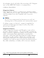
Disclaimer
No part of this document may be copied or reproduced
in any form or by any means without prior written
consent of ARRI. ARRI assumes no responsibility for any
errors that may appear in this document. The information is subject to change without notice. For actual
design, refer to the latest publications of ARRI data
sheets or data books, etc., for the most up-to-date specifications of ARRI products. Not all products and/or
types are available in every country. Please check with
an ARRI Sales Representative for availability and additional information.
While ARRI endeavours to enhance the quality, reliability and safety of the ARRI products, customers agree and
acknowledge that the possibility of defects thereof cannot be eliminated entirely. To minimize risks of damage
to property or injury (including death) to persons arising
from defects in the ARRI products, customers must incorporate sufficient safety measures in their work with the
system. ARRI or its subsidiaries does not assume any liability for infringement of patents, copyrights or other
intellectual property rights of third parties by or arising
from the use of ARRI products or any other liability arising from the use of such products.
No license, express, implied or otherwise, is granted
under any patents, copyrights or other intellectual property rights of ARRI or others. ARRI or its subsidiaries
expressly excludes any liability, warranty, demand or
other obligation for any claim, representation, or cause,
or action,or whatsoever, express or implied, whether in
contract or tort, including negligence, or incorporated in
terms and conditions, whether by statue, law or otherwise. In no event shall ARRI or its subsidiaries be liable for
or you have a remedy for recovery of any special,
direct, indirect, incidental, or consequential damages,
including but not limited to lost profits, lost savings, lost
revenues or economic loss of any kind or for any claim
by third party, downtime, good-will, damage to or
replacement of equipment or property, any costs or
recovering of any material or goods associated with the
assembly or use of our products, or any other damages
or injury of persons and so on or under any other legal
theory.
Preface
At the beginning of the 21st century, the entertainment
industry more than ever demands broader knowledge
and greater skill from contemporary cinematographers.
Being used for feature films, miniseries, documentary
films, music promos or advertisements, all these different
kinds of productions request dedicated and versatile
cinematographic equipment. Because of the variety of
assignments today and tomorrow, cameras must be
mounted on dollies and cranes, on tripods and special
rigs, on Steadicam and sophisticated three axis remote
controlled heads, operated from the shoulder or on the
lap, in several extreme atmospheric conditions – these
are only a few out of a wide range of different tasks –
nowadays equipment must be flexible enough to allow
the best possible work without having to accept compromises. So far, the inventive and creative cinematographer and his/her crew have to get hold of cameras and
accessories suitable for all kinds of working situations.
Based on the huge amount of expertise collected during
designing and producing such cameras as the ARRIFLEX
435, 535 and 765 or the MOVIECAM Compact and
SL as well as with the intention to fulfil most of the desires of today’s customers, the two leading companies in
the field, ARRI and MOVIECAM, have joined their
knowledge and inventive power to build a new line of
equipment, unifying the best of two worlds.
It was a real challenge for us to develop a system which
allows each cinematographer to set up the appropriate
equipment for each particular job more easily than ever
before.
PREFACE
01/2003
ARRICAM System Users’ Guide
3
Care and Cleaning
The solution was to build up a wide range of
compatible accessories around two camera bodies,
each one optimised for dedicated operations.
The ARRICAM System Users’ Guide we herewith
present to you is not simply an instruction manual to a
new camera, but a handbook of an equipment line that
includes the most quiet compact 35 mm camera for
multiple applications and increased utilization.
Please take time to read the following pages carefully.
You will see that the ARRICAM System offers you a
great variety of possibilities. Like the camera system
itself, its System Users’ Guide consists of several interchangeable parts that will continuously be updated.
In visiting our home page www.arri.com, you will find
all updated information about all components of the
system. Furthermore, interesting news and publications
can be downloaded from there.
Frédéric-Gérard Kaczek AAC and the ARRICAM Team
Preliminary Remarks
The ARRICAM System is based on two different camera
bodies, each one with special characteristics. Even
though there are some important differences, several
parts of the two bodies are comparable in function and
design. Therefore, you will find some common descriptions in the following pages.
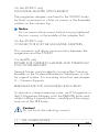
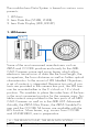
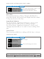
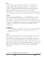
The ARRICAM System is almost maintenance-free.
There is only one requirement for a smooth operation:
the cameras and the accessories have to be meticulously clean. Therefore you should protect them against any
dirt or smudges.
Clean the camera exterior with a glass cleaner. Only
when really necessary, e.g. to remove camera tape
gum, alcohol or benzine should be used.
Caution!
1. When cleaning the equipment, do not moisten
connectors!
2. Never use acetone!
When applied properly, compressed air is the best
cleaner; a vacuum cleaner or an air syringe will do fine.
Cotton tips, orangesticks, soft and hard brushes may be
used for gentle cleaning.
Caution!
1. Compressed air should only be used for
blowing the magazines! Apart from this, high
pressure does more harm than good,
especially to glass surfaces.
2. The camera should only be lubricated at a
ARRICAM Maintenance Centre!
Design and technical data are subject to change!
PREFACE
01/2003
ARRICAM System Users’ Guide
4
CARE AND CLEANING
01/2003
ARRICAM System Users’ Guide
5
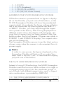
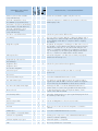
Table of Content
Copyright notes
Disclaimer
Preface
Preliminary remarks
Care & cleaning
Table of Content
Safety and Product specifications
1
2
3
4
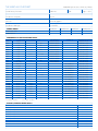
THE ARRICAM CAMERA BODIES
The cameras’ front, dust check, beeper, lens port
The cameras’ right sides
The cameras’ rear
The cameras’ left sides, Door
The Camera Control Panels
The list of warnings and messages
The cameras’ top
The camera bodies’ bases
The cameras’ interiors, Movement, Aperture Plate,
Spacer Plate, Format Masks
61
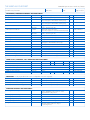
THE MAGAZINES & MAGAZINE ADAPTERS
The four ARRICAM Magazines
Care & cleaning
The Magazine Cover
The Coreholder
The Digital Footage Counter
Setting unit of measurement and ASA
The Tightening Wheels
The Remaining Footage Indicator
The Loop Protector
The four ARRICAM Magazines Adapters
Mounting/removing the Magazine Adapters
Mounting STUDIO Magazines on Adapters
Adapters’ Carrying Handles
The LITE Magazine Adapter
73
76
77
78
79
80
81
82
84
85
88
90
94
97
17
23
25
28
31
44
57
60
LOADING THE MAGAZINES,
THREADING THE CAMERAS
Loading the Magazines
Mounting Magazines and threading
101
106
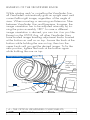
THE OPTICAL VIEWFINDER SYSTEM COMPONENTS
Introduction/Overview
The ARRICAM Viewfinders
The ARRICAM 100% Video Tops (1)
Mounting a Viewfinder
The Viewfinders’ housing
Viewing-filter lever
121
125
130
132
134
135
TABLE OF CONTENT
ARRICAM System Users’ Guide
6
3
4
5
6
10
01/2003
5
6
The Viewfinders’ Arms
Swivelling the Viewfinder Arms
Adjustment of the swivel friction
Ergonomy
Pivoting the Eyepiece
Levelling of the Viewfinder image
The swing-away de-squeezer
The Eyepiece
Mounting the Eyepiece
The Eyecup
The Heated Eyecup
The Eyepiece Extension Tubes
Viewfinder Levelling Rod
The ARRICAM Fieldlens & Groundglasses
The Frameglow Modules
137
137
138
140
141
142
143
144
145
146
147
148
150
151
153
THE ARRICAM VIDEO ASSIST SYSTEM
Important notes and safety specifications
The ARRICAM Video Assists’ components
The Video Assist
The 100% Video Tops (2)
Mounting the Video Assists
The connectors and the LED indicator
The mechanical adjustments of the CCD
The Video Assists’ Iris control dial
The Manual Gain Control button
The ON/OFF/CHECK/HIDE MENU switch & LED
The Menu/Store dial
The Video Assist On Screen Display (OSD)
The Video Menu Structure
The Video On Board Monitors
Control Menu of the 6.6” On Board Monitor
161
163
163
165
166
168
173
176
176
177
178
179
180
209
214
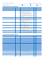
THE READOUT UNIT, THE LENS DATA SYSTEM
Mounting the Readout Unit & function
The Lens Data System (LDS)
The LDS Lenses
The Lens Data Boxes (LDB)
Mounting the Lens Data Boxes
The ARRICAM Studio LDB Adapter
Connectors and control LEDS
Connecting Lens Motors to the LDB
Lens Data Displays (LDD and LDD-FP)
Connecting the Lens Data Displays
The LDD and LDD-FP LEDs and controls
Function of the Lens Data Displays
The LDD Screen
The LDD-FP Screen
The LDD-FP Menu structure
Marking the Focus Scale
221
224
226
227
229
231
233
237
238
241
243
246
248
257
260
263
TABLE OF CONTENT
ARRICAM System Users’ Guide
7
01/2003
7
THE MANUAL CONTROL BOX
THE SPEED CONTROL BOX
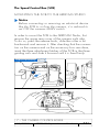
Introduction
Automatic exposure compensation
Stroboscopy, motion blur and depth of field.
The Manual Control Box (MCB)
The MCB Cable Adaptor
The Speed Control Box (SCB)
The Remote Control Station (RCS)
SCB connectors
SCB controls and displays
Functions and operations of the SCB
The ramping function
The synchronisation features
271
272
272
274
275
281
282
286
287
294
296
299
8
THE IN-CAMERA SLATE BOX
The In-camera Slate Box (ISB)
Mounting the ISB
The ISB LEDs and controls
The Jam-syncing
The ISB Handheld PC/Menu Structure
305
311
314
316
324
9
THE CAMERA SUPPORTS
Supports
Carrying Handles
Power Bridgeplate
The Camera Handgrips
The Shoulder Set
The Accessory Holders
The Universal Low Mode Set
341
342
345
348
349
351
352
10
11
THE POWER MANAGEMENT
357
MISCELLANEOUS
Standard 35/Super 35 Conversion
3 Perforation/4 Perforation Conversion
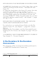
The Assistant Work Light
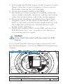
Checking the Mirror Shutter manually
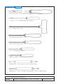
Tools
367
368
369
370
372
12
APPENDIX
Technical Data
Acronyms and Abbreviations
ARRI Group Addresses
Status, Warning and Troubleshooting List
The ARRICAM Checklist
Cables and Connectors
Lens Data Screens
Acknowledgment
TABLE OF CONTENT
ARRICAM System Users’ Guide
8
01/2003
THE CAMERA BODIES
Lens Port, Camera Control Panels, Movement, Aperture Plate,
Gate, Spacer Plate, Format Masks
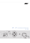
THE MAGAZINES AND THE MAGAZINE ADAPTERS
ST Magazines, LT Magazines, ST Mag Combi-Adapter,
Back Load Adapter, Top Load Adapter, LT Mag Adapter
LOADING THE MAGAZINES,
THREADING THE CAMERAS
THE OPTICAL VIEWFINDER SYSTEM COMPONENTS
ST Viewfinders, LT Viewfinders, Extension Tubes, Eyepiece,
Groundglasses, Frameglow Modules, Frameglow Masks
THE VIDEO ASSIST SYSTEM COMPONENTS
ST Video Assist, LT Video Assist, 100% Video Tops,
On Board Monitors
THE READOUT UNIT, THE LENS DATA SYSTEM
LDS Lenses, Lens Data Boxes, Lens Data Displays
THE MANUAL CONTROL BOX,
THE SPEED CONTROL BOX
MCB Adapter Cable, Remote Control Station
THE ARRICAM IN-CAMERA SLATE SYSTEM
In-camera Slate Box, Exposure Module, Handheld PC, OCR
THE CAMERA SUPPORTS
Power Bridgeplate, Shoulder Set, Carrying Handles, Brackets,
Universal Low Mode Set, Dovetail Attachment System
THE POWER MANAGEMENT
Batteries, Power Supply Unit
MISCELLANEOUS
Conversion Standard 35/Super 35, Assistant Work Light,
Conversion 4 Perf/3 Perf, Shutter Check Manually, Tools
APPENDIX
Technical Data, Acronyms, Addresses, Troubleshooting List,
Checklist, Cables and Connectors, Lens Data Screens
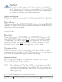
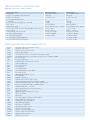
Safety Specifications
Important Notes
Warnings
• In wet weather the normal safety precautions for handling electrical equipment should be taken.
Note
Operational error possible!
Danger of injury or equipment damage possible!
General Safety Specifications
• Avoid operational errors!
• Clean optical surfaces only with a lens brush or a
clean lens cloth! In case of solid dirt moisten a lens
cloth with pure alcohol.
• Do not use solvents to clean the film gate!
Attention! Danger of injury! Never place your
hand in the lens port or inside of the camera
while it is RUNNING.
• Do not remove any screws which are secured with
paint!
• In order to ensure optimal performance, it is essential
that you acquaint yourself with this Users’ Guide.
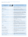
Product Specifications
• Assembly and initial operation should be carried out
only by persons who are familiar with the equipment!
In case of enquiries or when ordering parts, please
advise camera serial number and model.
• Switch OFF the camera MAIN switch before making
electrical connections (i.e. plugging on accessory
boxes)!
• Never RUN the camera without a lens or a protective
cap mounted in the lens port.
• Never operate the movement locking mechanism
while the camera is RUNNING!
• Ensure that the camera is securely mounted!
• Remove the battery cable before transport or servicing!
• Repairs should be carried out only by authorized
service centres!
• Use only original ARRI replacement parts and
accessories!
SAFETY SPECIFICATIONS
01/2003
ARRICAM System Users’ Guide
10
Note
This Users’ Guide applies to the ARRICAM Studio
and the ARRICAM Lite as well as the whole ARRICAM Accessory range. Sections that only apply to
one camera model or accessory type are indicated
as such in the heading.
Several items described in this Users’ Guide are in
preparation.
Because ARRI has already published several dedicated manuals about accessories, e.g. Follow Focus or
Matte Boxes, this components are not described
here.
The products and accessories recommended by the
manufacturer fulfill the specifications of the EU-Guideline 89/336/EWG.
SAFETY/PRODUCT SPECIFICATIONS
01/2003
ARRICAM System Users’ Guide
11
6
7
8
9
10
5
4
3
2
1
11
21
26
1
6
3
24
2
27
4
25 23 9
28
22
30
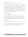
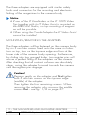
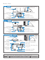
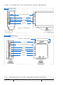
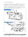
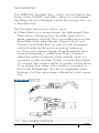
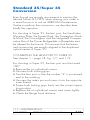
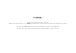
1
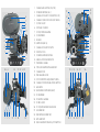
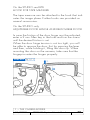
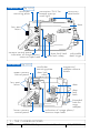
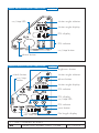
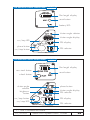
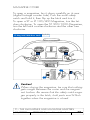
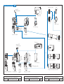
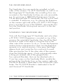
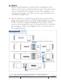
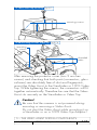
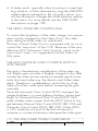
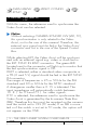
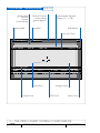
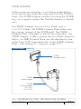
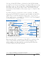
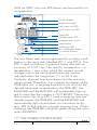
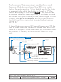
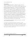
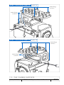
CAMERA MAIN SWITCH (ON/OFF)
2
POWER RECEPTACLE (24 V)
3
CAMERA ACCESSORY CONNECTOR (CAC)
4
CAMERA COVERS FOR ACCESSORY BOXES
5
ST VIDEO ASSIST
6
FOOTAGE COUNTER
7
ST 300/1000 MAGAZINE
8
ST VIEWFINDER
9
LDS LENS
10
MATTE BOX (MB 14)
11
CAMERA ACCESSORY ROSETTE
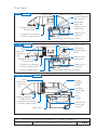
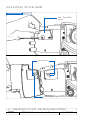
12
FOLLOW FOCUS
13
ST MEDIUM EXTENSION TUBE
14
MANUAL FOOTAGE INDICATOR
15
TIGHTENING WHEEL
16
TOP LOAD ADAPTER WITH HANDGRIP
17
CAMERA DOOR
18
TAPE MEASURE HOOK
19
ST DOOR FRICTION ADJUSTMENT SCREW
20
CAMERA CONTROL PANEL WITH RS BUTTON
21
BASE PLATE
22
LIGHTWEIGHT MATTE BOX (LMB 5)
23
LT VIEWFINDER
24
LT CARRYING HANDLE
25
LT VIDEO ASSIST
26
LT 120/400 SHOULDER MAGAZINE
27
SHOULDER PAD
28
RISER PLATE (SHOULDER SET)
29
LEFT HANDGRIP
30
RIGHT HANDGRIP WITH RUN/STOP BUTTON
14
15
13
8
9
10
16
17
18
19
20
21
12
22 9 23
29
2
24 25
28 20 17
26
27
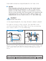
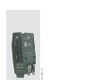
THE ARRICAM CAMERA BODIES
STUDIO
LITE
1
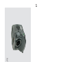
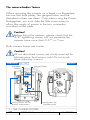
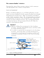
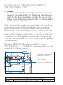
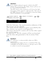
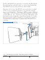
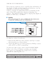
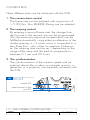
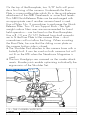
The Camera Bodies
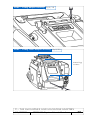
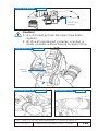
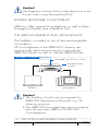
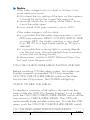
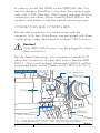
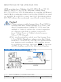
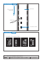
The cameras’ front
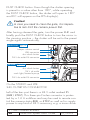
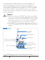
On the front of both cameras, an LDS 54 mm ARRI PL
(positive lock) lens port accepts lenses (spherical or
anamorphic) fitted with either LDS PL or with the well
established regular PL mounts. Depending on the way
the lens port is fitted to the camera front, the ARRICAM
Cameras will either allow shooting in Standard 35 or in
Super 35 format. The shooting mode is shown by the
number 1 (for 35) or 2 (for S35) facing the index.
Notice
It is recommended to ask a competent ARRICAM
Maintenance Centre or rental house to change the
format 35 to S35 or vice versa. If you have to do it
yourself, please see the related instructions in chapter
11 – Miscellaneous.
Different to the regular PL mounts of the ARRIFLEX and
MOVIECAM cameras, the LDS PL mounts of the ARRICAM Cameras are equipped with little electric contacts
required to communicate lens data to the camera. Two
sets of LDS contacts are integrated in each lens port to
allow the fitting of the lens according to the need of the
focus puller. So the indexes of the lens can be seen
wherever it is requested depending on the shooting situations: from the top and the bottom or from the left and
the right side of the camera.
Notice
Even though there is a difference between the LDS
PL mount and the PL mount, all lenses fitted with
PL mounts can be mounted in the new LDS PL port.
1 – THE CAMERA BODIES
01/2003
ARRICAM System Users’ Guide
17
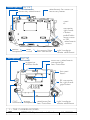
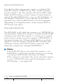
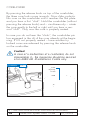
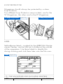
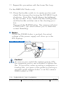
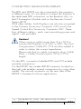
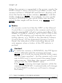
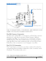
Studio front fig.1/1
LDB connector
beeper
beeper volume control
lens port lever
35/S35 index
lens port
35/S35 markings
unlock button
(only on extended
control panel)
dust check button
24 V dc outlet RS connector
Lite front fig.1/2
dust check button
24 V outlets
heatable eyecup/
work light
35/S35 index
35/S35 markings
lens port
lens port levers
24 V dc outlet RS connector
1 – THE CAMERA BODIES
ARRICAM System Users’ Guide
18
01/2003
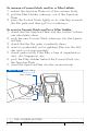
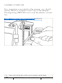
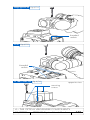
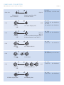
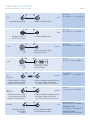
To remove a lens (or a lens port cover), rotate the two bayonet levers counter-clockwise as far as possible while grasping
the lens firmly. Then carefully slide the lens out of the port.
To fit a lens, align guide groove in the lens flange with
locating pin in the lens port. Insert the lens flange flat on
the receptacle, making certain the stud engages the lensflange hole easily. Rotate lens lock gently clockwise to
secure until the lens is seated properly. Do not use force!
Notice
1. Especially because of the weight of some lenses,
great care must be taken that the lens is mounted
in (or removed from) a straight line port.
2. The LDS Lens must be mounted in the 12 o’clock
or 3 o’clock position to enable the LDS functions.
3. When attaching the lens or a cover, take great
care not to harm any elements (e.g. LDS contacts).
4. Heavy and long lenses, such as ZEISS Variable
Prime Lenses or zoom lenses, must be supported
at all times by means of dedicated accessories.
5. When mounting an LDS Lens, one must be sure
that the little contacts and the mount itself are perfectly clean in order to assure good electric communication as well as an even fit of the lens on
the camera port.
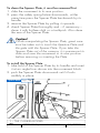
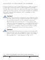
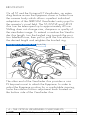
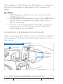
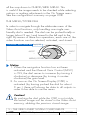
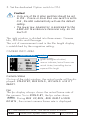
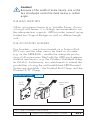
On the STUDIO and LITE
THE DUST CHECK BUTTON
Because the mirror and the movement are driven separately, moving the mirror by means of the inching knob
is not possible. It is also recommended not to move it
manually, there is danger of damage. To check the
gate, either by looking through the lens or by removing
it, turn the mirror out of the way by pushing briefly the
1 – THE CAMERA BODIES
01/2003
ARRICAM System Users’ Guide
19
DUST CHECK button. Even though the shutter opening
is preset to a value other than 180°, while operating
the DUST CHECK button, the shutter will open to 180°
and DC will appear on the FPS display(s).
Caution!
In case you need to clean the gate, it is imperative to turn OFF the camera power first.
After having cleaned the gate, turn the power ON and
briefly push the DUST CHECK button to turn the mirror in
the viewing position – the shutter will be set to the preset
angle again automatically.
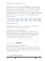
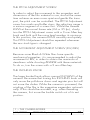
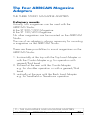
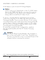
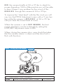
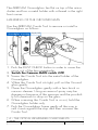
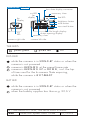
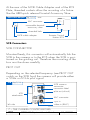
Studio front
fig.1/3
beeper volume control
LDB connector
dust check button
24 V dc outlet RS connector
Lite front fig.1/4
dust check button
24 V dc outlet
work light/heated eyecup
24 V dc outlet RS connector
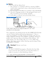
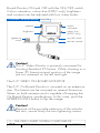
On the STUDIO and LITE
24V OUTLET RS CONNECTOR
Left of the lens port there is a 24 V outlet marked RS
(RUN/STOP). This three - pin Fischer connector is protected by a 1.6 A multifuse and may be used to remote control the camera status RUN or STOP as well as for supply
power to any kind of 24 V accessory, e.g. a zoom drive.
1 – THE CAMERA BODIES
20
ARRICAM System Users’ Guide
01/2003
On the STUDIO
BEEPER AND BEEPER VOLUME CONTROL
Only the ARRICAM Studio is equipped with a beeper.
Its volume can be increased in three steps by turning the
switch clockwise. The number shown on the switch will
indicate the adjustment: 1=low, 2=medium and
3=loud. When selecting the position 0, the beeper is
OFF. When the beeper is not turned OFF, it will sound
briefly when the camera is in RUN UP or RUN DOWN
status. It will beep intermittently as long as the camera is
RUNNING in ASYNC status.
On the STUDIO
LDB CONNECTOR
Hidden behind the front right side camera cover (fig.
1/3), a large connector is mounted on the camera
front. When the cover is removed, either a Lens Data
Box Cable Adaptor or the ST Lens Data Box itself can
be attached to this connector.
On the LITE
24 V HEATED EYECUP/WORK LIGHT OUTLETS
On both sides of the lens port, small connectors supply
the 24 V dc power for the following two accessories:
the Work Light and the Heated Eyecup.
1 – THE CAMERA BODIES
01/2003
ARRICAM System Users’ Guide
21
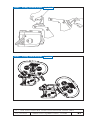
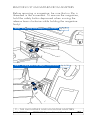
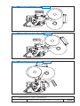
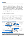
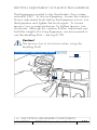
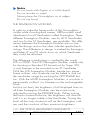
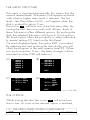
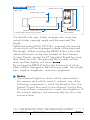
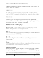
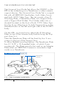
Studio right side fig.1/5
CAC connector
accessory attachments
attachments for covers or
accessory boxes
lens port
levers
RS connector
for right handgrip button
threaded holes
for lower cover
or ISB
attachments
screws
power
receptacle
main
switch
In-camera Slate
Box connector
right handgrip
rosette attachment
Lite right side fig.1/6
main switch
magazine
release knob
accessory attachments
connector for
Lens Data Box
lens port
levers
RS connector
for right handgrip button
CAC
power
connector receptacle
attachment for
Lens Data Box
1 – THE CAMERA BODIES
ARRICAM System Users’ Guide
22
right handgrip
rosette attachment
01/2003
The cameras’ right sides
On the STUDIO and LITE
RIGHT HANDGRIP ROSETTE ATTACHMENT
The right handgrip is screwed into the threaded socket
in the rosette centre.
On the STUDIO and LITE
CONNECTOR FOR THE RIGHT HANDGRIP
RUN/STOP BUTTON
The 24 V RS connector can either be used to supply 24 V
for accessories or to connect a switch for changing between
the RUN and STOP (i.e. STAND BY) status.
On the STUDIO and LITE
ACCESSORY ATTACHMENTS
The Carrying Handle or e.g. Universal Low Mode
Bracket is attached to the threaded sockets and gauged
holes on top of the right camera side.
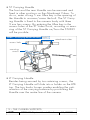
On the STUDIO and LITE
PROTECTING COVERS
Covers fig.1/7
Protecting covers are components of the ARRICAM
System and should be handled with care. When removing them from the camera bodies, immediately store
1 – THE CAMERA BODIES
01/2003
ARRICAM System Users’ Guide
23
them in the adequate cases. When no accessory box or
cable adapter is mounted on the camera, the appropriate protecting cover must be mounted instead of it to
protect the sensitive connectors!
On the STUDIO only
RELEASE KNOB OF THE UPPER PROTECTING COVERS
To remove an upper protecting cover, press the release
knob and slide the upper front cover forward or the
upper rear cover backwards. When mounting the protecting covers, be sure that they are flush to the camera
before sliding them into the locked position.
Notice
Do not tilt the upper covers during mounting or removing, and do not use force!
By removing the upper front cover the connector for the
ST Lens Data Box (ST-LDB) will appear.
By removing the upper rear cover the connector for the
Speed Control Box (SCB) will appear.
On the STUDIO only
RELEASE SCREW OF THE LOWER COVER
Remove the lower cover for mounting the In-camera
Slate Box (ISB).
On the LITE only
RELEASE SCREW OF THE COVER
To mount the LT-LDB on the LITE, you must first remove the
little cover by unscrewing one 3 mm hex screw.
1 – THE CAMERA BODIES
ARRICAM System Users’ Guide
24
01/2003
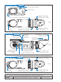
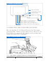
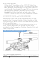
The cameras’ rear
On the STUDIO and LITE
CAC CONNECTOR FOR ACCESSORIES
The 16-pin Fischer connector, mounted oblique to facilitate the plug-in and labelled CAC (camera accessory
connector) is the main communication port of the
cameras. Several accessories can be attached there.
For further information see the accessory descriptions
and the fig. 1/8 and 1/9 on page 27.
POWER RECEPTACLE
The 2-pin Fischer power receptacle, mounted oblique to
facilitate the plug-in, is used to connect a 24 V battery
or a 24 V dc Power Supply Unit. Further information
about the power supply and power distribution of the
ARRICAM System is described in chapter 10 – Power
Management.
MAIN SWITCH
Protected by two flanges, the MAIN switch will interrupt
the power supply of all electronic components, except
the one of the clock in the In-camera Slate Box – it remains powered to keep the clock working.
SCREWS FOR MAINTENANCE PURPOSES ONLY
On both camera bodies, there are several screws which
are dedicated to maintenance work only. These screws
are marked with a special seal lacquer and/or a safety
label.
1 – THE CAMERA BODIES
01/2003
ARRICAM System Users’ Guide
25
Caution!
Do not touch these screws, otherwise severe
damage can occur!
CAMERA OPENINGS
One of the main differences between both camera
bodies is that you are able to mount ST Magazines either on top or on back of the STUDIO by means of a
magazine adapter while the LITE allows the attachment
of the lightweight LT Magazines on the rear side only. In
order to install ST Magazines on the LITE, you will have
to use the LT Magazine Adapter.
On the STUDIO only
REAR CAMERA OPENING AND MAGAZINE ADAPTER
ATTACHMENTS
In order to mount one of the three ST Magazine Adapters, swing the adapter towards the camera body while
taking care that the two adjusting pins enter the gauged
holes easily. Then you will have to screw the six retaining screws firmly – see caution on page 88.
On the STUDIO only
CONNECTOR FOR THE SCB AND MCB
These two connectors allow the mounting of the Speed
Control Box (SCB) and the Manual Control Box (MCB)
– see chapter 7.
Both connectors must be protected by covers if not used.
1 – THE CAMERA BODIES
ARRICAM System Users’ Guide
26
01/2003
Notice
If you intend to use the Manual Control Box (MCB)
or the MCB Cable Adapter and the Speed Control
Box (SCB) together, you must first mount the SCB and
then the MCB. To remove the SCB, you will first have
to remove the MCB from the camera.
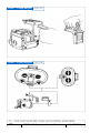
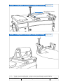
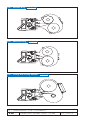
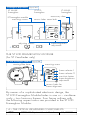
Studio rear fig.1/8
gauged holes and connector for the
magazine adapters
camera opening
MCB connector
SCB connector
attachements for
magazine adapters
CAC connector
power receptacle
main switch
door hinge
Lite rear fig.1/9
setscrew for maintenance only
release button for magazines/mag.adapter
electric contacts for
the magazine/
mag.adapter
main switch
CAC connector
power receptacle
camera opening
rails for the magazines/mag.adapter
1 – THE CAMERA BODIES
01/2003
ARRICAM System Users’ Guide
27
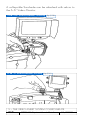
The cameras’ left sides
On the STUDIO and LITE
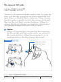
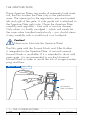
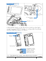
THE CAMERA DOOR
The door is located at the left camera side. To open the
door, pull the little spring-lock forwards and lift the lock
latch, then turn the lock latch clockwise. When closing
the door, press it gently towards the camera body and
then turn the lock latch counter-clockwise. When it is
closed, the door lock latch must be flush with the door;
the spring-lock keeps the lock in this position.
Notice
When closing the door, be sure that the movement,
the film guides and the buckle switch are placed in
the correct position. When the movement is in its
loading position, the door cannot be closed.
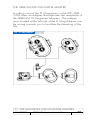
Door Lock fig.1/10
door lock safety
door lock latch
2.
1.
3.
1 – THE CAMERA BODIES
ARRICAM System Users’ Guide
28
01/2003
On the STUDIO and LITE
HOOK FOR TAPE MEASURE
The tape measure can be attached to the hook that indicates the image plane. Further hooks are provided on
several accessories.
On the STUDIO only
ADJUSTABLE DOOR HINGE AND REMOVABLE DOOR
In case the friction of the door hinge must be adjusted,
enter a 2 mm Allen key in the hole and turn the screw
until the desired friction is set.
When the door hinge tension is not too tight, you will
be able to remove the door, first by pressing the lever
and then, while holding it, lifting the door up. When
mounting the door on the camera, take care that the
hinge-pins enter the hinges properly.
Studio Door fig.1/11
2.
1.
➡
1 – THE CAMERA BODIES
01/2003
ARRICAM System Users’ Guide
29
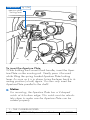
Studio left side fig.1/12
viewfinder
mounting plate
connectors 24 V for
heated eyecup
work light
accessory
attachment
door
lens port
levers
camera control panel
indication of image plane/
measure tape hook
Lite left side
door lock latch adjustable
door hinge
door lock safety
fig.1/13
viewfinder
mounting plate
upper camera
control panel
door lock
safety
lens port
levers
magazine/
adapter release
button
door
door
lock
latch
threaded
hole for
mag.
adapter
lower camera
control panel
indication of image plane/
measure tape hook
1 – THE CAMERA BODIES
ARRICAM System Users’ Guide
30
01/2003
On the STUDIO only
CONNECTORS
Power (24 V) for the Heated Eyecup and the Work Light
is supplied via two connectors.
On the STUDIO only
ACCESSORY ATTACHMENT
The two threaded sockets and two gauged holes on top of
the camera left side allow mounting of several accessories
including a bracket for Steadicam, a similar support system
or the modular ARRICAM Carrying Handle System.
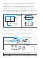
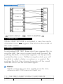
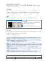
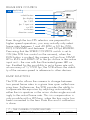
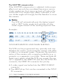
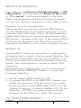
The cameras’ control panels
On both, the STUDIO and the LITE, most of the functions
can be controlled and monitored by means of the elements assembled to similar Camera Control Panels.
These Panels, located on the camera left side, are easily
accessible and visible for the operator and the focus
puller. All elements placed on the Panel are identical on
both cameras. Beside the buttons and push wheels, two
kind of displays are provided: the LEDs and the alphanumeric displays.
Either a Standard or an Extented Camera Control Panel
can be installed by Maintenance Technicians on both
cameras. The ST and the LT Standard Control Panels
are equipped with FPS push wheel input units. On the
ST and LT Extended Camera Control Panels, FPS and
Shutter opening will be set by means of little buttons
instead of pointed items. Furthermore, the ST Extended
Camera Control Panel has a third display to show the
film length.
1 – THE CAMERA BODIES
01/2003
ARRICAM System Users’ Guide
31
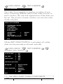
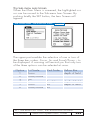
The Extended Camera Control Panels also allow the
user to select several settings offered in the display
options’ menu.
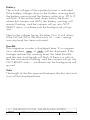
DISPLAY OPTIONS’ MENU
In addition to the regular operational mode, two further
display modes are available in the ARRICAM System:
• The Service mode will be used by the Maintenance
Personnel only.
• The Options mode is dedicated to the users.
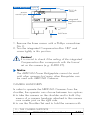
BASICS
All messages shown on the displays of several components (Camera Body, Accessory Boxes, Video Assists,
Readout Unit, etc.) are generated by computer software
(SW). Together with a firmware (FW), the SW is integrated in the camera bodies and several system components.
Depending on the type of Camera Control Panel (Standard or Extended), different indications and messages
will be shown on the FPS display. As with other computer systems, and based on the feedback by ARRICAM
Users, the software and also the firmware will be updated when necessary. Therefore it is advisable to know
the version of the software and firmware installed in
your camera.
Also when requesting information, the technician will
ask you the software and firmware version number. Last
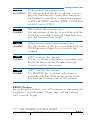
but not least, is also necessary to be aware that some
messages can be changed without notice when the
system is updated.
Because some messages are exclusively for the
ARRICAM Maintenance Personnel, they are not listed in
this Users’ Guide.
1 – THE CAMERA BODIES
ARRICAM System Users’ Guide
32
01/2003
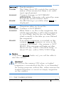
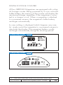
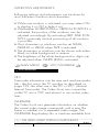
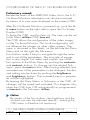
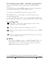
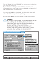
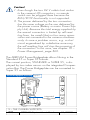
OPERATIONS
The Option mode allows the user
• to define the threshold voltage value that must be
reached to initiate the low battery warning.
• to check the software/firmware version installed in
several components.
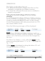
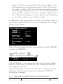
Setting the threshold voltage of the low battery
warning
To set the threshold voltage of the low battery warning,
first turn OFF the camera power. Then, enter the Option
mode by holding the BRIGHT button on the Camera
Control Panel (camera left side) pressed and turn ON
the camera MAIN switch.
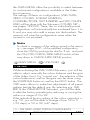
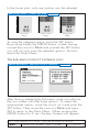
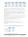
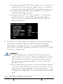
Now the following messages will be displayed:
display:
text:
shutter
LBat
FPS
NiCd
Footage
or
User
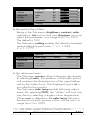
N i c d shows that the low battery warning is set to a
default value for Nickel Cadmium batteries. This default
value is set in the factory and cannot be changed by
the users.
If a Lithium Ion battery is used, select the User mode
either by pushing the button “C” or “D” – see page 36,
fig. 1/14
When User is displayed, pushing the button “B” will
change the display as follows:
display:
text:
shutter
LBat
FPS
V21.7
Footage
User
1 – THE CAMERA BODIES
01/2003
ARRICAM System Users’ Guide
33
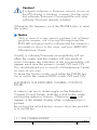
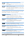
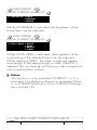
By pushing the buttons “C” or “D”, the threshold voltage
can be set anywhere from 20.0 V to 29.9 V.
To save the change of the threshold value in the system,
either push the PHASE button on the Extended Camera
Control Panel or switch OFF and ON the camera
MAIN switch.
While pushing the PHASE button, the actual voltage of
the power supply will appear on the FPS display.
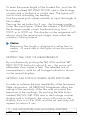
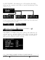
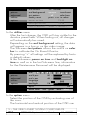
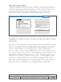
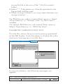
Checking the software and firmware version installed
in several components
To find out which SW or FW version is actually installed, first turn OFF the camera power, then, enter the
Option mode by holding the BRIGHT button on the
Camera Control Panel pressed (camera left side) and
turn ON the camera MAIN switch.
Now the following messages will be displayed:
display:
text:
shutter
LBat
FPS
NiCd
Footage
or
User
By pushing either the button “C” or “D”, the display will
change as follows:
display:
text:
shutter
CLD
FPS
V100
Footage
SW
This means that the Software Version 100 has been
installed in the Camera Control Panel. By pushing either
“C” or “D”, the display will change to a next component or to FW if SW is already shown.
display:
text:
shutter
SCB
FPS
104c
1 – THE CAMERA BODIES
ARRICAM System Users’ Guide
34
Footage
FW
01/2003
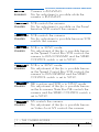
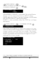
Caution!
If a figure (software or firmware version) shown on
the FPS display is blinking, it means that the installed software/firmware is incompatible with other
software/firmware already installed.
Whenever this happens, push the PHASE button to reset
the system.
Notice
Only in case of a very serious problem (risk of damaging the camera, risk of wrong film exposure) the
RUN LED will glow red to indicate that the camera is
not ready to shoot. In this case, call your ARRICAM
Maintenance Centre.
Usually, a software/firmware incompatibility will not
affect the system and the camera will stay ready to
shoot. However, the indication of the incompatibility will
appear each time the power is turned OFF and ON.
This should remind you to consult a Maintenance Centre
as soon as you can.
To leave the Option mode, push either the PHASE button or switch the camera MAIN switch OFF and ON.
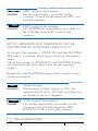
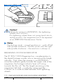
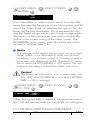
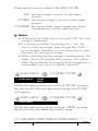
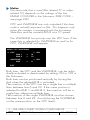
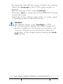
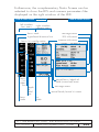
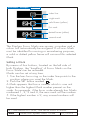
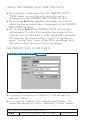
HANDLING THE EXTENDED CAMERA CONTROL
PANEL
In order to set fps or shutter angle on the Extended
Camera Control Panels, hold the unlock button while
pushing the selectors’ buttons. Otherwise LOCK will
appear in the related display when a setting button is
pushed.
By pushing the unlock button, arrows show the possibility to set the fps.
1 – THE CAMERA BODIES
01/2003
ARRICAM System Users’ Guide
35
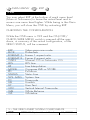
ACRONYMS
SCB
MCB
LDB
LDD
WRC
ISB
CCB
SW
FW
CLD
speed control box
manual control box
lens data box
lens data display
wireless remote control
in-camera slate box
camera control box (ARRIMOTION/Jogbox)
software
firmware
camera left display
BAT LED INDICATOR
The bat LED (only located on the LT Standard Camera
Control Panel) lights up red in case the supply voltage
drops below the threshold value defined in the option
mode. The same indication is provided on the other
Camera Control Panels by a warning message on the
FPS display.
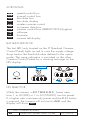
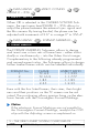
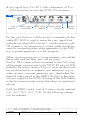
Extended Camera Control Panel
fig.1/14
A
C
B
D
FPS SELECTOR
While the camera is NOT RUNNING, frame rates
from 1 to 40 (LITE) or 1 to 60 (STUDIO) can be preset.
If a higher rate is erroneously preset and the RUN button
is pressed, the camera will not start to RUN and the
display will show FPS! .
1 – THE CAMERA BODIES
36
ARRICAM System Users’ Guide
01/2003
Notice
If an SCB is connected to the camera and it’s SPEED
CONTROL switch is set to ON, the FPS selector on
the camera left side is put out of service and either
S C B will be shown on the FPS display of the Standard Camera Control Panel or the value preset on
the SCB will be shown on the FPS display of the
Extended Camera Control Panel while the camera
is STAND BY. As soon as the camera is RUNNING,
the actual fps rate will be shown.
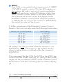
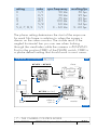
A further advantage of the Extended Camera Control
Panels is that you can also enter the following frame rates:
shown on control panel
6.2 fps
12.5 fps
16.6 fps
23.9 fps
29.9 fps
33.3 fps
real setting
6.25 fps
12.5 fps
16.666 fps
23.976 fps
29.97 fps
33.333 fps
All settings are only possible while the camera is not
RUNNING. RUN will appear in the related display
when a setting button is pushed while the camera is
RUNNING.
If a component like the SCB, the MCB or the WRC has
control over the shutter opening, no setting of the shutter
angle will be possible by means of the Camera Control
Panel buttons and the controlling device will be displayed.
1 – THE CAMERA BODIES
01/2003
ARRICAM System Users’ Guide
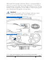
37
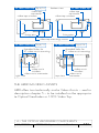
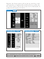
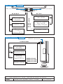
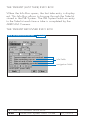
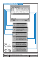
Studio Standard Camera Control Panel fig.1/15
run/stop LED
shutter angle selector
shutter angle display
FPS display
FPS selector
run/stop button
phase button
Studio Extended Camera Control Panel
fig.1/16
brightness button
unlock button
run/stop
button
shutter angle selector
phase button
shutter angle display
FPS selector
FPS display
run/stop LED
FPS selector
reset button
raw stock button
film length display
1 – THE CAMERA BODIES
38
ARRICAM System Users’ Guide
01/2003
Lite Standard Camera Control Panel fig.1/17
film length display
reset button
battery LED
shutter angle selector
shutter angle display
run/stop LED
FPS display
phase button
run/stop button
FPS selector
Lite Extended Camera Control Panel
fig.1/18
film length display
raw stock button
reset button
unlock button
shutter angle
selector
phase button
shutter angle display
FPS selector
brightness
button
FPS display
run/stop button
run/stop LED
FPS selector
1 – THE CAMERA BODIES
01/2003
ARRICAM System Users’ Guide
39
RUN/STOP BUTTON
Provided that the main power supply is switched ON
and the camera is READY (e.g. film is laced correctly,
power supply is ok), the camera will start to RUN when
either the RUN button on the Camera Control Panel or
one of the other RUN buttons, e.g. on the Handgrip, on
the Speed Control Box or on a remote control unit is
pressed. Any of those RUN buttons can be employed
alternately to change the status of the camera RUN or
STOP and vice versa.
RUN LED INDICATOR
The RUN LED is off while the camera is in STAND BY or
not powered. When the camera is started, the RUN LED
will glow red while the camera is coming up to speed,
and switch to green once the camera is RUNNING at
the preset frame rate. When a RUN button is pushed
again to stop the camera, the RUN LED will glow red
while the camera SLOWS DOWN, and turns OFF
when the camera has stopped RUNNING.
Notice
If the RUN LED glows red while the camera is not
RUNNING, it indicates that the camera is not ready
– pushing a RUN button will have no effect.
If the camera is powered, the cause why the camera
is not in STAND BY status will be displayed on the
FPS displays – see page 44.
1 – THE CAMERA BODIES
ARRICAM System Users’ Guide
40
01/2003
SHUTTER ANGLE SELECTOR
While the camera is NOT RUNNING, but of course
powered, you may change the shutter angle either by
pushing with a pointed item – e.g. toothpick – the little
selector protected by the Plexiglas cover on the Standard Camera Control Panel or by pushing the button on
the Extended one. As soon as one is pushed, the shutter
advances to the new setting. The value cycles in the
following steps:
11.2° 22.5° 30° 43.2° 45° 60°
75° 86.4°
90° 105° 120° 135° 144° 150° 172.8° 180°
PHASE BUTTON
Depending on the status of the camera, the PHASE
button allows two different operations.
When the camera is STAND BY:
While pressing the PHASE button continuously, the
INCHING mode is activated and the movement will
RUN at 1 FPS as long as the button is held down.
When the button is released, the mirror shutter will
automatically park in the viewing position.
While the camera RUNS in the INCHING mode the
actual power voltage will be displayed in the FPS
display as e.g. V 24.6 .
When the camera is RUNNING:
pushing the PHASE button will increase the preset FPS
rate by 0.2 fps as long as the button is held down. This
also works when e.g. the SCB or another remote device
controls the fps rate.
1 – THE CAMERA BODIES
01/2003
ARRICAM System Users’ Guide
41
Exceptions:
While the camera is controlled
• by an SCB, the SCB switch is set to SYNC and the
PHASE switch is set to FIXED,
• by a Video Assist external synchronization signal.
• by an In-camera Slate Box synchronization signal.
• by an external device and RUNNING a SPEED
RAMP the PHASE button is inactive. When it is pushed, the FPS display will show FIXD as long as the
button is held pressed.
FPS DISPLAY
Regarding the brightness control of displays
Many components of the ARRICAM System are fitted
with similar displays. The brightness of all these displays
can be adapted to the needs of the users by means of
the dimmers located e.g. on the Speed Control Box, on
the Manual Control Box or on the Readout Unit. The
adjustment of the display brightness will automatically
affect all components connected to the camera body,
individual adjustments per display is not possible.
Regarding the messages shown on the FPS displays
All messages described on the following pages are generated by the ARRICAM SW Version 3.0. When requesting information from ARRICAM Maintenance Technicians, please mention the version of the software installed
on your camera. To know which software version is actually installed, you have to press the BRIGHT button on the
Extended Camera Control Panel before turning the MAIN
switch ON. As soon as the camera is powered, the software version will be displayed as long as the button is
held pressed.
In case no warning is displayed, the setting of the com1 – THE CAMERA BODIES
ARRICAM System Users’ Guide
42
01/2003
ponent that actually has control over the camera is
shown on the FPS display of the Extended Camera
Control Panel. Simultaneously, the controlling component is shown e.g on the Readout Unit. As soon as you
attempt to change the FPS value on the Extended
Camera Control Panel, its FPS display will show the
component which actually controls the camera (e.g.
MCB, SCB, WRC) – no changes will be possible there.
The four digit display marked FPS will not only show the
actual frame rate while the camera is RUNNING, but
will also serve as an important central information display. Warning messages will alternatively show up with
the fps values. If there is more than one warning message, they will alternate at a two seconds frequency.
When there is no reason for displaying warning messages, the FPS displays will inform about the following status.
Notice
As soon as the camera detects that software of several components (e.g. Lens Data Box, Video Assist)
are not compatible, the warning SW will appear
on the FPS displays and the camera will go to NOT
READY. Simultaneously, Phse will appear on the
SHUTTER displays. By pushing one of the PHASE
buttons, the warnings will disappear and the camera
goes to STAND BY. The warnings will appear automatically when the camera is powered ON in order
to remind you to ask as soon as possible a ARRICAM Maintenance Centre to up-date the system.
1 – THE CAMERA BODIES
01/2003
ARRICAM System Users’ Guide
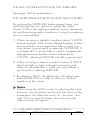
43
Explanation of the message, glows
Explanation of the message,
glows alternately with an other message
MESSAGE
(
MESSAGE
)
(( MESSAGE )) Explanation of the message, blinks
‹‹ MESSAGE ›› Explanation of the message, blinks fast
STANDBY
NOT READY
RUNNING
REMARK
The indicated status informs why the
camera is e.g. not ready or which component has control over the camera.
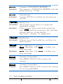
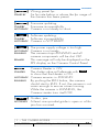
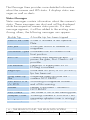
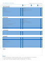
LIST OF MESSAGES AND WARNINGS on the FPS
display (Software Version 3.0)
FPS DISPLAY
Camera is not powered.
....
REMARK
running point
REMARK
0.0
STANDBY
24.0
RUNNING
Electronic problem.
An electronic problem occurs that can only
be fixed by Maintenance Technicians.
Electronic problem.
An electronic problem occurs that can only
be fixed by Maintenance Technicians.
Camera is not RUNNING.
Camera is ready to shoot with the preset fps
shown on the FPS selector (Standard Camera
Control Panel) or displayed (Extended Camera
Control Panel).
Camera is RUNNING.
Camera is RUNNING with the preset fps
(e.g. 24 fps).
1 – THE CAMERA BODIES
ARRICAM System Users’ Guide
44
01/2003
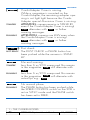
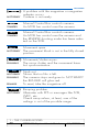
FPS DISPLAY
Camera is RUNNING REVERSE.
The camera is RUNNING REVERSE with the
preset fps (e.g. 12 fps).
-12.0
RUNNING
Asynchronity.
Camera RUNS at another fps than the preset rate.
As y
RUNNING
((
))
Ba t
NOT READY
RUNNING
((
))
Bu k l
NOT READY
(
CAL
)
STANDBY
RUNNING
CCB
STANDBY
–CCB
STANDBY
Battery low.
The power source does not supply the
requested voltage.
If the camera cannot reach the preset fps
rate, Bat and the current fps rate will alternatively light up on the display.
See more – chapter 10, page 363.
Buckle trip.
At least one of the buckle trip switches has
been tripped.
Lens calibration in progress
C A L alternates with F P S or further warning message.
C A L alternates with F P S or further warning message.
Camera Control Box.
The ARRIMOTION CCB controls the
camera.
Camera Control Box.
The ARRIMOTION CCB controls the camera
for shooting REVERSE.
1 – THE CAMERA BODIES
01/2003
ARRICAM System Users’ Guide
45
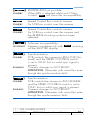
FPS DISPLAY
(
Covr
)
STANDBY
RUNNING
((
DC
))
NOT READY
En d
STANDBY
RUNNING
Fi x d
RUNNING
Combi-Adapter Cover is missing.
While a magazine is mounted on the
Combi-Adapter, the remaining adapter opening is not light tight because the CombiAdapter special Aluminium Cover is missing.
ATTENTION: camera remains in STAND BY
even if the Combi-Adapter Cover is missing!
C o v r alternates with F P S or further
warning messages.
ATTENTION: camera can RUN even when
the Combi-Adapter Cover is missing!
C o v r alternates with F P S or further
warning messages.
Dust check.
The DUST CHECK or PHASE button has
been pushed while the camera is STAND
BY.
Film end warning.
Less than 6 m/20 ft unexposed film remain
in the magazine. End will alternate with
0.0 .
Less than 6 m/20 ft unexposed film remain
in the magazine. End will alternate with
actual fps e.g.: 24.0 .
No manual phase.
The PHASE button has been pushed while
the SPEED CONTROL switch on the SCB is
set on SYNC mode and the PHASE switch
has been set to FIXED.
1 – THE CAMERA BODIES
ARRICAM System Users’ Guide
46
01/2003
FPS DISPLAY
((
FPS!
))
Wrong preset fps.
An fps rate below or above the fps range of
the camera has been preset.
))
Firmware updating.
Firmware incompatibility.
Camera is not ready to shoot.
STAND BY
((
!FW!
STANDBY
NOT READY
((
!SW!
))
STANDBY
NOT READY
((
Hbat
))
NOT READY
RUNNING
REMARK
Heat
STANDBY
NOT READY
RUNNING
((
Jam
))
NOT READY
Software updating.
Software incompatibility.
Camera is NOT READY.
The power supply voltage is too high.
Camera is not ready.
The camera stops RUNNING and all
camera components will be shut OFF.
This message will only be displayed on the
FPS display on the Camera Control Panel.
Camera Heater is ON.
The shutter value will alternate with Heat .
to show that the Heater is ON.
Camera remains in STAND BY.
By pushing the RUN button, the camera
should start to RUN. If not, the camera is not
warm enough to ensure correct running.
While the camera is RUNNING, the
Camera Heater turns itself OFF.
Guides, jam.
At least one sprocket guide is open or a film
jam has occurred.
1 – THE CAMERA BODIES
01/2003
ARRICAM System Users’ Guide
47
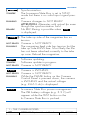
FPS DISPLAY
((
Mag
))
NOT READY
Manual Control Box controls camera.
An MCB has control over the camera.
MCB
STANDBY
Manual Control Box controls camera.
An MCB has control over the camera and
the REVERSE shooting mode has been selected on the SCB.
-MCB
STANDBY
Movm
NOT READY
((
M/S!
Out
Movement/shutter async.
The mirror shutter and the movement have
lost synchronization.
))
Stock out.
Shows that no film is left.
The camera stops and goes to NOT READY
the RUN LED will glow red.
To reset, take the magazine off.
NOT READY
RUNNING
REMARK
(
RAMP
Movement open.
The movement block is not in the fully closed
position.
))
RUNNING
((
A problem with the magazine or magazine
adapter occurs.
Camera is not ready.
) Ramping problem.
Alternates with FPS or messages like SCB,
WRC, etc.
Check ramp values, at least, one of the
settings is out of the possible range.
NOT READY
1 – THE CAMERA BODIES
ARRICAM System Users’ Guide
48
01/2003
FPS DISPLAY
((
))
Rev!
STANDBY
Speed Control Box controls camera.
An SCB has control over the camera.
SCB
STANDBY
Speed Control Box controls camera.
An SCB has control over the camera and
the REVERSE shooting mode has been
selected.
– SCB
STANDBY
((
))
SW
NOT READY
(
Syn
)
STANDBY
RUNNING
(
–Syn
STANDBY
RUNNING
REVERSE RUN not possible.
When REV is selected while an LT Mag.
is used, Rev! will show the incompatibility.
)
Software incompatibility.
Appears simultaneously with
on the SHUTTER display.
Phse
warning
Synchronization.
SCB controls the camera to RUN FWD (forward) and the SPEED CONTROL switch
is set to SYNC but no valid sync signal is
present.
Camera changes to NOT READY.
ATTENTION: Alternates with actual fps even
though the synchronization fails!
Synchronization.
SCB controls the camera to RUN REVERSE
and the SPEED CONTROL switch is set to
SYNC but no valid sync signal is present.
Camera changes to NOT READY.
ATTENTION: Alternates with actual fps even
though the synchronization fails!
1 – THE CAMERA BODIES
01/2003
ARRICAM System Users’ Guide
49
FPS DISPLAY
(
Tc S y
)
STANDBY
RUNNING
REMARK
((
TkUp
))
NOT READY
RUNNING
Updt
STANDBY
NOT READY
V 24.6
NOT READY
RUNNING
V 3.3
Synchronization.
The In-camera Slate Box is set in SYNC
mode but there is no valid input signal present.
Camera changes to NOT READY.
ATTENTION: Alternates with actual fps even
though the synchronization fails!
No REV filming is possible when TcSy
is displayed.
The take up side of the magazine has no
tension.
Camera is NOT READY.
The magazine feed side has tension but the
take up side RUNS free. Most likely the film
has not been attached correctly to the take
up core. Reload the magazine.
Software updating.
Software update in progress.
Camera is NOT READY.
Camera is INCHING.
Camera is NOT READY.
While the PHASE button on the Camera
Control Panel is pressed down, the camera
is INCHING and the actual voltage
(e.g. 24.6 V dc) is displayed.
In-camera Slate Box power management.
The ISB battery voltage (e.g. 3.3 V) will
appear while the TEST button on the
In-Camera Slate Box is pushed.
1 – THE CAMERA BODIES
ARRICAM System Users’ Guide
50
01/2003
FPS DISPLAY
(
Vi S y
)
STANDBY
RUNNING
REMARK
Wi n d
NOT READY
RUNNING
REMARK
Synchronization.
The Video Assist IVS controls the synchronization of the camera but there is no valid
input signal present.
Camera changes to NOT READY.
ATTENTION: Alternates with actual fps even
though the synchronization fails!
No REV filming is possible when ViSy is
displayed
Magazine takes up loose film.
Camera is NOT READY.
Either there is no film in the magazine, the
whole exposed film is still in the magazine
or, most likely, the film has not been attached correctly to the take up core. Reload
the magazine.
If an empty magazine is mounted on the
camera, Wind appears as soon as the
camera is powered – the camera is NOT
READY. The message will fade out after
about 25 sec. with a 120/400 Mag. or
about 35 sec. with a 300/1000 Mag.
Notice
Only when Wind
start the camera.
fades out, you will be able to
Caution!
Do not turn the camera ON when a loaded
magazine is mounted but the film is not threaded.
For testing purposes without film, either remove the
loaded magazine or mount an empty magazine
on the camera.
1 – THE CAMERA BODIES
01/2003
ARRICAM System Users’ Guide
51
FPS DISPLAY
WRC
STANDBY
– WRC
STANDBY
WRC.
A Wireless Remote Control has control over
the camera.
WRC controls camera.
A Wireless Remote Control has control over
the camera and the REVERSE shooting mode
has been selected.
FURTHER MESSAGES ARE ONLY DISPLAYED ON THE
EXTENDED CAMERA CONTROL PANELS
FPS DISPLAY/EXTENDED CAMERA CONTROL PANEL ONLY
‹‹
CCB
STANDBY
‹‹
– CCB
STANDBY
LOCK
STANDBY
‹‹
MCB
STANDBY
‹‹
– MCB
STANDBY
›› CCB controls the camera.
No fps adjustment is possible on the
Camera Control Panel because ARRIMOTION CCB/Jogbox controls the camera.
›› CCB controls the camera.
No REVERSE fps adjustment is possible
because ARRIMOTION CCB/Jogbox
controls the camera.
Camera Control Panel is locked.
Press the UNLOCK button to adjust the fps.
›› MCB controls the camera.
No fps adjustment is possible on the
Camera Control Panel because MCB controls the camera.
›› MCB controls the camera.
No REVERSE fps adjustment is possible
because MCB controls the camera.
1 – THE CAMERA BODIES
ARRICAM System Users’ Guide
52
01/2003
FPS DISPLAY/EXTENDED CAMERA CONTROL PANEL ONLY
RUN
RUNNING
‹‹
SCB
STANDBY
‹‹
– SCB
STANDBY
‹‹
Syn
STANDBY
‹‹
– Syn
STANDBY
‹‹
Tc S y
STANDBY
‹‹
Vi S y
STANDBY
Camera is RUNNING.
No fps adjustment is possible while the
camera is RUNNING.
›› SCB controls the camera.
No fps adjustment is possible on the Panel
because SCB controls the camera.
›› SCB controls the camera.
No fps adjustment is possible because SCB
controls the camera.
›› SCB is in SYNC mode.
No adjustment of the fps is possible because the Speed Control Box SCB controls the
camera to RUN FORWARD and the SPEED
CONTROL switch is set to SYNC.
›› SCB is in SYNC mode.
No adjustment of the fps is possible because the Speed Control Box SCB controls the
camera to RUN REVERSE and the SPEED
CONTROL switch is set to SYNC.
›› ISB is active and SCB is in SYNC mode.
No adjustment of the fps is possible because the In-camera Slate Box ISB controls the
camera and the SPEED CONTROL switch is
set to SYNC.
›› IVS controls the camera.
No adjustment of the fps is possible because Video Assist IVS controls the camera.
1 – THE CAMERA BODIES
01/2003
ARRICAM System Users’ Guide
53
FPS DISPLAY/EXTENDED CAMERA CONTROL PANEL ONLY
‹‹
WRC
STANDBY
‹‹
– WRC
STANDBY
›› WRC controls the camera.
No fps adjustment is possible on the
Camera Control Panel because WRC controls the camera.
›› WRC controls the camera.
No REVERSE fps adjustment is possible on
the SCB because WRC controls the
camera.
LIST OF MESSAGES AND WARNINGS ON THE
SHUTTER - DISPLAY (SOFTWARE VERSION 3.0)
As long as the camera is STAND BY and the SHUTTER
SET button is pushed, the display will show the preset
value.
While the camera is RUNNING, the SHUTTER display
will automatically show the actual shutter opening
angle.
Beside this, the SHUTTER display is also used to show
further information.
SHUTTER DISPLAY
Shutter closed.
The In-camera Slate System is ON, the
camera RUNS UP or DOWN, and the mirror shutter is set to 0 degrees.
ISB0
RUNNING
((
CCB
STANDBY
))
CCB controls the camera.
No shutter adjustment is possible on the
Camera Control Panel because ARRIMOTION CCB controls the camera.
1 – THE CAMERA BODIES
ARRICAM System Users’ Guide
54
01/2003
SHUTTER DISPLAY
((
E rr
))
STANDBY
NOT READY
Camera Control Panel is locked.
Press UNLOCK button to change the shutter
setting.
Lock
STANDBY
((
MCB
))
MCB controls the camera.
No shutter adjustment is possible on the
Camera Control Panel because MCB controls the camera.
))
Camera is RUNNING.
The shutter adjustment is not possible while
the camera is RUNNING.
))
SCB controls the camera.
No shutter adjustment is possible on the
Camera Control Panel because SCB controls the camera.
STANDBY
((
Run
RUNNING
((
SCB
STANDBY
(
Shutter problem.
Shutter error. The actual shutter angle does
not equal the preset shutter setting.
When a shutter error occurs, the camera
stops and changes to NOT READY.
) The Timing Shift Box TSB is operational.
Alternates with shutter angle.
RUNNING
Alternates with shutter angle.
TSB
STANDBY
((
WRC
STANDBY
))
WRC controls the camera.
No shutter adjustment is possible on the
Camera Control Panel because WRC controls the camera.
1 – THE CAMERA BODIES
01/2003
ARRICAM System Users’ Guide
55
SHUTTER DISPLAY
REMARK: The following message will not be displayed
on the Extended Camera Control Panel.
(
MCB
)
STANDBY
RUNNING
((
Phse
))
NOT READY
Shutter selector is pushed while the Manual
Control Box MCB switch is set to control the
shutter.
Alternates with shutter angle.
Alternates with shutter angle.
Software incompatibility.
Appears simultaneously with the
warning in the FPS display.
SW
REMARK: By pushing one of the PHASE buttons the
camera goes in STAND BY status.
1 – THE CAMERA BODIES
ARRICAM System Users’ Guide
56
01/2003
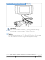
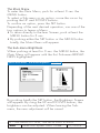
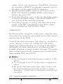
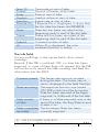
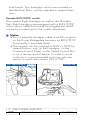
The cameras’ top
On STUDIO & LITE
EXCHANGEABLE ENGRAVED VIEWFINDER
MOUNTING PLATE
The engraved Viewfinder Mounting Plate shows the format the camera has actually been adjusted to – either
STANDARD 35 or SUPER 35 format – see fig. 1/19.
▲
Notice
The adjustment should be done by trained personnel
of ARRICAM Maintenance Centres or rental houses.
If, for some reason, you have to change the format of
the camera, please see the description of the procedure in chapter 11 – Miscellaneous.
Guided the gauged holes, the viewfinder systems are
flanged on the plate next to the glass surface and attached to the threaded sockets. Be sure that both plugs
connect easily.
Viewfinder Mounting Plate
fig.1/19
viewfinder attachments
(threaded sockets)
format label
viewfinder attachments
(gauged holes)
On STUDIO & LITE
ADJUSTING SCREWS
Caution!
Do not touch the adjusting screws – they must be
used by technicians of the ARRICAM Maintenance Centres only!
1 – THE CAMERA BODIES
01/2003
ARRICAM System Users’ Guide
57
Studio top fig.1/20
lens cap
viewfinder
mounting plate
viewfinder
connector
viewfinder
window
dovetail bracket
for accessories
tape
measure
hook
magazine adapter
attachment
adjustable
door hinge
CAC connector
connector for the
magazine adapters
Lite top
fig.1/21
lens cap
viewfinder
mounting plate
viewfinder
connector
door
hinge
tape
measure
hook
attachment for
accessories
viewfinder
window
release knob for magazines/adapter
1 – THE CAMERA BODIES
58
ARRICAM System Users’ Guide
01/2003
On the STUDIO only
MAGAZINE ADAPTER ATTACHEMENT
The magazine adapters are fixed to the STUDIO body
by firmly screwing two of the six screws in the threaded
sockets on the camera top.
Notice
Do not secure these screws before having tightened
the two screws in the middle of the adapter first!
On the STUDIO only
CONNECTOR FOR THE MAGAZINE ADAPTERS
This connector will allow communication between the
magazines and the STUDIO.
On the LITE only
FIXTURE FOR CARRYING HANDLE AND STEADICAM
LOW MODE BRACKET
Several fixtures are provided to mount either Carrying
Handles or the Universal Bracket for Steadicam or similar support system. For mounting instruction see chapter
9 – Camera Supports.
RELEASE-KNOB FOR MAGAZINE UNLOCKING
To remove a camera opening cover, an LT Magazine or
the LT Magazine Adapter, push the RELEASE knob and,
while holding it pressed down, carefully pull the magazine out of the LITE body.
Caution!
Do not touch the adjusting screws!
1 – THE CAMERA BODIES
01/2003
ARRICAM System Users’ Guide
59
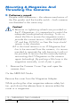
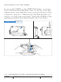
The camera bodies’ bases
When mounting the camera on a head or a Baseplate,
be sure that both plates, the gauged holes and the
threaded sockets are clean. Only when using the Power
Bridgeplate, you must slide the little cover away to
allow the supply of power to the two connectors
provided on the plate.
Caution!
Before fixing the camera, please check that the
3/8” tightening screws will not penetrate the
camera base more than 0.27” or 7 mm.
Both camera bases are similar.
Caution!
All not described screws are strictly reserved for
Maintenance Technicians only! Do not touch
these adjusting screws!
Lite base
Studio base fig.1/22
threaded
sockets
sliding cover of the
power connectors
gauged holes
attachment for
shoulder pad
1 – THE CAMERA BODIES
ARRICAM System Users’ Guide
60
01/2003
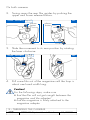
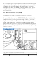
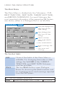
The camera bodies’ interiors
Despite the size of the camera interior, both cameras
are equipped with similar components.
THE MOVEMENT
Either a 4 Perf pull-down or a 3 Perf pull-down movement can be installed in both camera bodies by trained
Maintenance Technicians. Both movements are fitted
with similar operation items. By swinging the movement
locking lever clockwise, the movement will slide backwards into the loading position. By swinging the lever
counter-clockwise, the movement block will slide forwards to the Aperture Plate.
Caution!
• Before sliding the movement to the loading
position, turn the INCHING knob until the index
is in the LOOP position.
• In order to secure the movement in its shooting
position, push the lever counter-clockwise to
overcome a mechanical resistance which will
hold the movement firmly in this front shooting
position.
Movement fig.1/23
spacer plate
front film guide
spacer plate handle
spacer plate safety spring
movement
locking lever
inching knob
movement
adjustment screw
pitch
adjustment screw
1 – THE CAMERA BODIES
01/2003
ARRICAM System Users’ Guide
61
62
ARRICAM System Users’ Guide
lower loop marking
lower buckle switch
lower film guide releasing knob
lower film guide
lower sprocket/loop adjustment sprocket roller
buckle switch
upper film guide
upper sprocket/loop adjustment sprocket roller
aperture plate locking lever (see fig. 1/25 and 1/28)
upper film guide releasing knob
upper buckle switch
upper loop marking
Lite Interior
fig.1/24
Studio Interior
1 – THE CAMERA BODIES
01/2003
THE PITCH ADJUSTMENT SCREW
In order to adjust the movement to the properties and
dimensions of the film material in use, and at the same
time achieve an even more quiet and gentle film transport, the pitch can be controlled. The PITCH Adjustment
screw has marks and buffer stops; the adjusting range is
a narrow segment of a screw turn. While the camera
RUNS at the normal frame rate (24 or 25 fps), slowly
turn the PITCH Adjustment screw with a 3 mm Allen key
back and forth until the noise level reaches its minimum.
In this position, the camera RUNS smoothly and quitely.
This PITCH Adjustment should be repeated when-ever
the raw stock type is changed.
THE MOVEMENT ADJUSTMENT SCREW (FW/REV)
Because some Black & White films have specific
mechanical properties, it is recommended to adjust the
movement to REV, in order to obtain the maximum of
steadiness while shooting REVERSE with these materials.
To do so, turn the screw with a 3 mm Allen key.
THE INCHING KNOB
The large knurled knob allows manual INCHING of the
camera. Be aware that turning this INCHING knob will
only move the pull-down claws and register pins but will
not move the shutter. While the camera is powered, the
winding of the film in the magazine engenders automatically. If this should be avoided, e.g. when threading
the camera, first move the buckle switch out of its rest
position.
1 – THE CAMERA BODIES
01/2003
ARRICAM System Users’ Guide
63
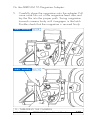
THE APERTURE PLATE
These Aperture Plates are made of extremely hard material; the film touches the Plate only in the perforation
area. The openings for the registration pins are located
left and right of the gate. A side guide rail is attached to
the Aperture Plate right side. Clean the Aperture Plate
carefully and regularly – best with a vacuum cleaner.
Only when it is badly smudged – which will rarely be
the case when handled meticulously – you should clean
it very carefully with a small brush or a toothpick.
Caution!
Never ever lubricate the Aperture Plate!
The film gate with the Format Mask and Filter Holder
is integrated in the Aperture Plate. A set with several
Format Masks is available. If it is intended to shoot with
open gate, it is recommended to use the Universal
Format Mask in order to avoid the risk of image overlapping and flare.
Aperture Plate
fig.1/25
gate
in-camera
slate window
1 – THE CAMERA BODIES
ARRICAM System Users’ Guide
64
01/2003
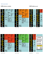
UNIVERSAL (open gate)
1 : 1.33 Full aperture (ANSI)
1 : 1.375 Academy
1 : 1.66
1 : 1.85
1 : 2.35
S35 / 1 : 1.78
S35 / 1 : 1.85 (ANSI)
S35 / 1 : 1.85 (Asymmetric)
S35 / 1 : 2.35 (ANSI)
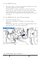
MOUNTING AND REMOVING THE APERTURE PLATE
In order to check the gate, to exchange a Format Mask
or a filter, the Aperture Plate must be extracted out of the
camera body.
To extract the Aperture Plate:
1. turn the camera MAIN switch OFF
2. turn the INCHING knob until its marking matches the
LOOP index
3. swing the movement locking lever clockwise until the
movement reaches its rear position
4. lift the Aperture Plate locking lever while holding the
black handle of the Format Mask in order to avoid
that the Aperture Plate hits the movement block
5. take hold of the Aperture Plate by the Format Mask
handle, lift it and extract the Aperture Plate.
Caution!
• The surfaces where the Aperture Plate meets the
camera body must be meticulously clean – any
dirt might alter the flange focal distance.
• In case the Aperture Plate is slanting, start inserting again.
1 – THE CAMERA BODIES
01/2003
ARRICAM System Users’ Guide
65
Studio Interior
fig.1/26
aperture plate
locking lever
To insert the Aperture Plate:
While holding the Format Mask handle, insert the Aperture Plate on the mouting rail. Gently press it forward
while lifting the spring loaded Aperture Plate locking
lever. As soon as it is in place, bring the lever back to its
resting position (= lock) again. You can only insert the
Aperture Plate parallel to the shaft!
Notice
For mounting, the Aperture Plate has a V-shaped
notch at its bottom edge. This notch must be absolutely clean to make sure the Aperture Plate can be
seated properly.
1 – THE CAMERA BODIES
ARRICAM System Users’ Guide
66
01/2003
Studio Interior
fig.1/27
aperture plate
v-shaped notch
Caution!
When inserting the Aperture Plate in the camera,
be sure that the locking lever completely returns in
its receptacle. The correct resting position is flush
with the Plate.
THE FORMAT MASKS AND THE FILTER HOLDER
Caution!
• A Format Mask and a Filter Holder must always
be inserted in the Aperture Plate.
• The Aperture Plate can only be locked if the
Filter Holder and the Format Mask are correctly
inserted.
1 – THE CAMERA BODIES
01/2003
ARRICAM System Users’ Guide
67
To remove a Format Mask and/or a Filter Holder:
1. extract the Aperture Plate out of the camera body
2. pull the Filter Holder sideways out of the Aperture
Plate
3. press the Format Mask lightly on its side flap towards
the film gate and then pull it out sideways
To insert a Format Mask and/or a Filter Holder:
1. check that the Aperture Plate and the contact surface
are absolutely clean
2. push the new Format Mask sideways into the Aperture Plate
3. check that the film gate is perfectly clean
4. insert (or preferably not) a gelatine filter into the Holder and cut it appropriately
5. check meticulously if the filter is free of imperfection,
dust, dirt, fingerprint, etc.
6. push the Filter Holder behind the Format Mask into
the Aperture Plate
7. insert the Aperture Plate into the camera body.
Aperture Plate
fig.1/28
filter holder
format mask
1 – THE CAMERA BODIES
ARRICAM System Users’ Guide
68
01/2003
Notice
• Sliding the movement block forwards when the
Aperture Plate is not correctly in place can cause
damage to the camera!
• The presence of a filter in the film gate will be
shown on the Lens Data Display and on the System
Line on the video monitor.
Caution!
• Be careful not to damage Aperture Plate or gate
– this might have serious consequences!
• If it is not absolutely necessary, avoid placing a
gelatine filter in the film gate. Even a microscopic air bubble or dirt will be seen extremely
enlarged on the screen.
• If there is no other alternative and you have to
use a filter in the gate, do not forget to clearly
mark the type of filter inserted in the camera.
THE IN-CAMERA SLATE WINDOW
The Aperture Plate has two slots for the pull-down claws
and a round window that allows the exposing of the
In-camera Slate on the film. The slots as well as the
surface of the Aperture Plate and the little window must
always be clean – check regularly.
THE SPACER PLATE
In the centre of the front film guide, there is an opening
for the Spacer Plate. This Plate – held by a spring loaded fixture – has raised surfaces that hold the film in the
gate plane. Smudged surfaces inevitably cause film
scratches!
1 – THE CAMERA BODIES
01/2003
ARRICAM System Users’ Guide
69
To clean the Spacer Plate, it must be removed first
1. slide the movement to its rear position.
2. press the safety spring fixture downwards, at the
same time press the Spacer Plate backwards by its
handle.
3. remove the Spacer Plate by pulling it upwards
4. check Spacer Plate thoroughly and – if necessary –
clean it with lint-free cloth or a toothpick. Also clean
the rear of the Spacer Plate.
Caution!
While manipulating the Spacer Plate, great care
must be taken not to touch the Aperture Plate and
the gate with the Spacer Plate. If you take the
Spacer Plate out of the camera, it is paramount to
slide and save the movement in its rear position
before removing or inserting the Plate.
To install the Spacer Plate
1. take hold of the Spacer Plate by its handle and insert
it at an angle from above into the movement block.
2. push the Spacer Plate downwards until it locks
audibly in place.
Spacer Plate
fig.1/29
1 – THE CAMERA BODIES
ARRICAM System Users’ Guide
70
01/2003
THE ARRICAM MAGAZINES, THE MAGAZINE ADAPTERS
2
The Four ARRICAM Magazines
Convention: In the following description, the cover is
considered being the magazine front. So a mounted
magazine will have the latches on the camera left side.
All ARRICAM Magazines are built to ensure the smoothest and most quiet operation possible. Therefore highend electronics and mechanical components have been
assembled in rugged but lightweight shells. Due to the
characteristics of the material used and the special treatment of the surfaces, heat up to 40° C/104° F will not
affect the good operation of the ARRICAM Equipment. If
the ambient temperature will drop under -10° C/-14° F,
thermostatically controlled heaters will assure automatically the adequate temperature in the cameras and the
ST Magazines. In case of heavy frost, a Heater Barney
will do fine. Motors, heater and digital footage counter
are located at the rear of the magazines.
The roller assemblies contain three or four rollers. Roller
bearings should be serviced at an ARRICAM Maintenance Centres only. The roller assembly is best cleaned
with a vacuum cleaner.
The ARRICAM System includes four magazines, each
one deserves the best specific application.
1.
2.
3.
4.
ST 300/1000 Magazine for STUDIO and LITE
ST 120/400 Magazine for STUDIO and LITE
LT 120/400 Shoulder Magazine for LITE only
LT 120/400 Steadicam Magazine for LITE only
Caution!
No other ARRI or MOVIECAM Magazine can be
used with the ARRICAM Cameras.
2 – THE MAGAZINES AND MAGAZINE ADAPTERS
01/2003
ARRICAM System Users’ Guide
73
ST Mag 300/1000 fig.2/1
ST Mag 120/400 fig.2/2
LT Mag 120/400 Shoulder fig.2/3
LT Mag 120/400 Steadicam fig.2/4
2 – THE MAGAZINES AND MAGAZINE ADAPTERS
74
ARRICAM System Users’ Guide
01/2003
The two main differences between the ST and the LT
Magazines are that only the ST Magazines allow filming
in REVERSE mode and they are equipped with heaters.
Both ST Magazines allow FORWARD filming from 1
to 40 fps with the LITE and from 1 to 60 fps with the
STUDIO. With both cameras, the ST Magazines allow
shooting REVERSE from 1 to 32 fps.
Notice
• When using the ARRICAM Studio with a Steadicam or a similar device, no special magazine is
needed because of the design of the Rear Load
Adapter.
• To mount the ST Magazines on the ARRICAM Studio, one of the three magazine adapters is necessary – see fig. 2/16 and 2/18 on pages 86 and
87.
• To use the ST Magazines on the ARRICAM Lite, the
LT Mag Adapter must be used – see fig. 2/28 on
page 97.
• LT Magazines will be mounted on the ARRICAM
Lite without any adapters.
Because of the size of the ST 300/1000 Magazine,
secure it when the equipment is operated under extreme
g-force conditions by mounting the Magazine Stabilizing Bracket.
ST 300/1000 Mag Stabilizing Bracket
fig.2/5
magazine
stabilizing
bracket
2 – THE MAGAZINES AND MAGAZINE ADAPTERS
01/2003
ARRICAM System Users’ Guide
75
An adapter which will allow the mounting of LT Magazines on the ARRICAM Studio is in preparation.
CARE & CLEANING
Magazine Interior
The magazines interior’s coating has to be thoroughly
clean. Remove any smudges immediately! Clean interior
and film plates from dust carefully with a vacuum
cleaner.
Notice
Do not use compressed air because you will risk
blowing dust or film particles into inaccessible areas!
A rubber o-ring is in the lid – inspect it regularly for
mechanical damage and clean it with a dry cloth –
do not use solvents!
Magazine Exterior
Clean magazine lacquer and Plexiglas cover with a
window cleaner (caution – do not moisten connector!).
Keep connector, tightening wheels and footage counter
clean and inspect them regularly for mechanical
damage. Clean the light trap plate thoroughly before
attaching it to the camera. Check the connector and
remove possible dust out of the recesses by blowing
carefully, e.g. with an aerosol spray (avoid blowing on
the roller assembly), or better, with a vacuum cleaner.
2 – THE MAGAZINES AND MAGAZINE ADAPTERS
ARRICAM System Users’ Guide
01/2003
76
MAGAZINE COVER
To open a magazine, lay it down carefully on its rear
(digital footage counter side). Push the small safety
catch and hold it; then flip up the latch and turn it.
To open a ST or LT 120/400 Magazine, turn the latches clockwise. To open the ST 300/1000 Magazine,
turn the left latch counter-clockwise and the other one
clockwise.
ST Mag 300/1000 Door Latch fig.2/6
Caution!
When closing the magazine, be sure that nothing
gets caught between the cover and the magazine’s bottom. Be aware that the safety catch engages properly in the latch, both parts must fit flush
together when the magazine is closed.
2 – THE MAGAZINES AND MAGAZINE ADAPTERS
01/2003
ARRICAM System Users’ Guide
77
COREHOLDER
By pressing the release knob on top of the coreholder,
the three core locks move inwards. Now slide a plastic
film core on the coreholder until it reaches the film plate
and you hear a first ”click”. Hold the coreholder (without
pressing the release knob) and – simultaneously – rotate
the core gently to the left or right until you hear a second ”click”. Only now the core is properly seated.
In case you do not hear the ”clicks”, the coreholder pin
has engaged in the slit of the core already at the beginning. If it is not properly seated – have another try.
Locked cores are released by pressing the release knob
on the coreholder.
Caution!
In case of a malfunction of a coreholder, do not
disassemble it – the magazine should be serviced
at an ARRICAM Maintenance Centre only.
Coreholder fig.2/7
core
release
knob
2 – THE MAGAZINES AND MAGAZINE ADAPTERS
78
ARRICAM System Users’ Guide
01/2003
DIGITAL FOOTAGE COUNTER
All four ARRICAM Magazines are equipped with a digital footage counter. Being powered by its own on-board
buffer battery, the memory of the counter will display the
remaining footage, regardless if the magazine is mounted to a camera or not. When a magazine is attached
to a powered camera, the magazine’s buffer battery
recharges automatically.
In case nothing is displayed (which happens very rarely), simply mount the magazine to a powered camera to
reactivate the display. The magazine battery usually
recharges automatically during the shooting period.
ST Mag Footage Counter
fig.2/8
LT Mag Footage Counter
fig.2/9
2 – THE MAGAZINES AND MAGAZINE ADAPTERS
01/2003
ARRICAM System Users’ Guide
79
To enter the preset length of the loaded film, push the little button marked SET RAW STOCK next to the footage
counter with a toothpick or similar item. The figure will
start to blink indicating the feeding.
Use the preset push wheel switches to input the length of
film loaded.
Pressing the set button for 2 sec., the footage counter
stores the input figure. When the camera is RUNNING,
the footage counter counts backwards (e.g. from
0305 m to 0000 m). The display on the magazine will
always show the remaining footage, even when the
camera is filming reverse.
Notice
Remaining film length is displayed in either feet or
metres – a mark next to the figure shows the preset
option.
SETTING THE UNIT OF MEASUREMENT
By simultaneously pushing the SET ASA and the SET
RAW STOCK button for about 3 sec., the cursor will
alternately show metre or feet. The selected unit of
measurement is valid for all footage indications shown
on the several displays.
SETTING ASA FOR IN-CAMERA SLATE EXPOSURE
In order to achieve the best readability of the In-camera
Slate information, all ARRICAM Magazines allow the
setting of the sensitivity of the film and so control the
exposure of the markings. By pushing the little button
marked SHOW/SET ASA next to the footage counter
display with a toothpick, the cursor will move on the
display, from m or ft to ASA, and the set sensitivity will
appear for about 3 sec.
2 – THE MAGAZINES AND MAGAZINE ADAPTERS
ARRICAM System Users’ Guide
01/2003
80
By using the push wheel switches, the desired sensitivity
can be preset and by pushing 2 sec. the SET ASA button it will be fed into the system.
Notice
• In feeding the ASA rate of the film in the system,
please consider if the film will be processed to the
initial sensitivity or if it will be pushed. So e.g. if a
250 ASA film will be pushed 1 stop, a rate of
500 ASA should be fed in.
• Because the displays of the LT Magazines have
only four digits, no cursor will appear when selecting the ASA rate.
Caution!
All four digits must always be used in feeding the
rate, so for example 0320 .
TIGHTENING WHEELS
As long as power is supplied to the camera, the magazine’s incorporated electronically controlled motors will
assume a permanent and appropriate film tightening.
It is recommended to tighten the film manually in the
magazine by turning the tightening wheels before connecting the camera to the power supply.
A tightening wheel for each side is built into the cover
of the two ST Magazines. By depressing the tightening
wheel, you may turn the core via friction plates in the
direction of the arrow. The spring which brings the tightening wheel back to its resting position can be checked
by depressing it slightly.
2 – THE MAGAZINES AND MAGAZINE ADAPTERS
01/2003
ARRICAM System Users’ Guide
81
ST Mag Tightening Wheel
fig.2/10
Caution!
While the camera is RUNNING, the tightening
wheels must not turn!
If a tightening wheel does not swing back into its
resting position, the magazine has to be repaired
at an ARRICAM Maintenance Centre.
Notice
The fed raw stock – wound emulsion in – pulls off left
side spindle clockwise. The film winds onto the right
side spindle clockwise – the emulsion is always in.
REMAINING FOOTAGE INDICATOR:
The ST 300/1000 Magazine has, complementary to
the digital footage counter, also a remaining film length
indicator. Only when the camera is not RUNNING,
move the indicator gently towards the upper side of the
magazine; the footage indicator lever will swing
towards the film roll. The film length remaining in the
magazine’s left half – usually the unexposed film –
is shown on a scale located between both tightening
wheels.
2 – THE MAGAZINES AND MAGAZINE ADAPTERS
ARRICAM System Users’ Guide
01/2003
82
Although the footage indicator lever is spring-loaded to
return to a neutral position when released, it should be
moved back manually. The footage indicator arm should
lie flat on the magazine cover interior. Check spring and
arm attachment by gently moving them.
Caution!
Due to the length of the footage indicator lever,
care should be taken when checking it!
ST Mag manual footage indicator
ST Mag footage lever
fig.2/11
fig.2/12
2 – THE MAGAZINES AND MAGAZINE ADAPTERS
01/2003
ARRICAM System Users’ Guide
83
LOOP PROTECTOR
Magazines should always be protected by a clean
Loop Protector.
Two different Loop Protectors are provided, one for the
ST Magazines, the other one for the LT Magazines.
ST Mag Loop protector
fig.2/13
LT Mag Loop protector
LABEL
Self-adhesive labels, supplied by the ARRICAM Maintenance Centres, can be slid into a holder at the outside
of the magazines. Use these labels to identify film
during shooting and stick them later onto the film cans.
Label
fig.2/14
2 – THE MAGAZINES AND MAGAZINE ADAPTERS
ARRICAM System Users’ Guide
01/2003
84
The Four ARRICAM Magazine
Adapters
THE THREE STUDIO MAGAZINE ADAPTERS
Preliminary remarks
Actually, two magazines can be used with the
ARRICAM Studio:
• the ST 300/1000 Magazine
• the ST 120/400 Magazine
No other magazines can be mounted on the ARRICAM
Studio.
The use of an adapter is always necessary for mounting
a magazine on the ARRICAM Studio.
There are three possibilities to mount magazines on the
ARRICAM Studio:
1. horizontally at the top with the Top Load Adapter or
with the Combi-Adapter e.g. for operation with
geared/fluid head
2. inclined at the rear with the Combi-Adapter
e.g. for shoulder operation or with a geared/fluid
head
3. vertically at the rear with the Back Load Adapter
e.g. for handheld or Steadicam operation
2 – THE MAGAZINES AND MAGAZINE ADAPTERS
01/2003
ARRICAM System Users’ Guide
85
Studio – ST Mag Adapter fig.2/15
Studio – ST Mag Adapter fig.2/16
2 – THE MAGAZINES AND MAGAZINE ADAPTERS
ARRICAM System Users’ Guide
01/2003
86
Studio – ST Mag Combi-Adapter
fig.2/17
Studio – ST Mag Combi-Adapter fig.2/18
2 – THE MAGAZINES AND MAGAZINE ADAPTERS
01/2003
ARRICAM System Users’ Guide
87
The three adapters are equipped with similar safety
locks and connectors for the mounting and electronic
linking of the magazines to the camera body
Notice
• If one of the LT Viewfinders or the LT 100% Video
Top together with its LT Video Assist is mounted on
the ARRICAM Studio, no top mounting of magazine will be possible.
• When using the Combi-Adapter the LT Video Assist
cannot be installed.
MOUNTING/REMOVING THE ADAPTERS
The three adapters will be fastened on the camera body
by six 3 mm hex screws fixed onto the same six holes:
two on top, two on the top-rear edge and two at the
lower side of the camera body opening. Furthermore,
by sliding into two gauged holes, two register pins will
assure a perfect fitting of the adapters on the camera.
After checking that all contact surfaces are absolutely
clean, swing the adapter forward towards the camera
until the register pins engage.
Caution!
Depress gently on the adapter and first tighten
both 3 mm hex screws on the top-rear edge
(middle) of the adapter.
Then tighten the four remaining screws. When
removing the adapter, also unscrew the middle
screws first – see fig. 1/8 on page 27.
2 – THE MAGAZINES AND MAGAZINE ADAPTERS
ARRICAM System Users’ Guide
01/2003
88
Studio – ST Mag Adapter mounting fig.2/19
Studio – ST Mag Combi-Adapter mounting fig.2/20
mounting
screws
2 – THE MAGAZINES AND MAGAZINE ADAPTERS
01/2003
ARRICAM System Users’ Guide
89
MOUNTING ST MAGAZINES ON ADAPTERS
Position the back part of the magazine’s roller assembly
on the rear/lower dovetail of the magazine adapter.
Pull the film loop with your left hand through the adapter
opening into the camera. Swing the magazine carefully
forward towards the adapter until it engages in the
magazine latch.
Caution!
When attaching the magazine, pay attention that
the film does not get caught between the magazine and the dovetail on the adapter opening!
Because the lock mechanism is very quiet, pay
attention that the magazine is mounted firmly before releasing it. To double check carefully that the
magazine is properly seated and locked, briefly
pull the magazine away from the camera.
Caution!
To avoid that the powered camera automatically
pulls the film into the magazine when mounting it,
either switch the power OFF or open one of the
film guides first – see chapter 3, fig. 3/7.
2 – THE MAGAZINES AND MAGAZINE ADAPTERS
ARRICAM System Users’ Guide
01/2003
90
REMOVING ST MAGAZINES FROM ADAPTERS
Before removing a magazine, be sure that no film is
threaded in the movement. To remove the magazine,
hold the safety button depressed when moving the
release lever clockwise while holding the magazine
firmly!
Studio – ST Mag Top Load Adapter, release button
Studio – ST Mag Back Load Adapter, release button
fig.2/21
fig.2/22
2 – THE MAGAZINES AND MAGAZINE ADAPTERS
01/2003
ARRICAM System Users’ Guide
91
CAMERA COVER CAP
If no magazine is mounted on the camera, you should
always attach a Camera Cover Cap to the adapter.
The engraving ARRICAM must cover the electric connectors.
Studio – ST Mag Back Load Adapter, Cover Cap
fig.2/23
2 – THE MAGAZINES AND MAGAZINE ADAPTERS
ARRICAM System Users’ Guide
01/2003
92
Notice
• While shooting with the Combi-Adapter, its Cover
Cap with handgrip must obviously be installed to
avoid light entering the camera. In order to be
safe, the warning Covr will appear on the FPS
displays to remind you to cover the cavity.
• The Combi-Adapter Cover Cap with detachable
handgrip is not compatible with the one of the
other magazine adapters.
Studio – ST Mag Combi-Adapter, Cap and Handgrip
fig.2/24
2 – THE MAGAZINES AND MAGAZINE ADAPTERS
01/2003
ARRICAM System Users’ Guide
93
ADAPTERS’ CARRYING HANDLES
A handgrip is part of each ST Mag Adapter.
Notice
When using an LT Viewfinder or the LT 100% Video
Top on the ARRICAM Studio, you must first remove
the handgrip from the Back Load Adapter before
being able to install the LT Video Assist.
To do so, unscrew the four maintaining 3 mm hex
screws by using the 3 mm Allen key and remove the
Carrying Handle. Now unscrew the two 3 mm screws
out of the bottom part of the removed Carrying Handle
and fix them in the two threaded sockets on the adapter’s front. Do not forget to replace these screws when
mounting the Carrying Handle!
To carry the camera in this configuration, replace
the removed Handle with the ST Centre Carrying
Handle.
Caution!
On the ST Mag Combi-Adapter, the handgrip is
part of the removable Cover Cap. Therefore you
must be sure that the cover is mounted firmly to the
adapter before carrying the camera.
2 – THE MAGAZINES AND MAGAZINE ADAPTERS
ARRICAM System Users’ Guide
01/2003
94
Studio – ST Mag Back Load Adapter, Handgrip mounting
fig.2/25
mounting screws
Studio – ST Mag Back Load Adapter, Handgrip mounting
fig.2/26
2 – THE MAGAZINES AND MAGAZINE ADAPTERS
01/2003
ARRICAM System Users’ Guide
95
MOUNTING THE LT MAGAZINES ON THE
ARRICAM LITE
Before being able to install a magazine, the ARRICAM
Lite Camera Cover Cap must be removed. Press the LT
Mag/LT Mag Adapter release button and slide the
cover out of the camera body. Now carefully slide the
LT Magazine onto the rails until you hear a gentle click.
When closing the camera door, the magazine will automatically be held in the correct position.
Lite – Magazine attachment
fig.2/27
threaded holes for
LT mag adapter
LT magazine/LT mag
adapter release button
camera
cover cap
2 – THE MAGAZINES AND MAGAZINE ADAPTERS
ARRICAM System Users’ Guide
01/2003
96
THE ARRICAM LITE MAGAZINE ADAPTER
In order to mount the ST Magazines on the LITE, ARRICAM offers an adapter that replicates the receptacle of
the ARRICAM ST Magazine Adapters. The adapter
door located at the left side of the LT Mag Adapter can
be swung towards you to facilitate the threading of the
film.
Lite – LT Mag Adapter
fig.2/28
2 – THE MAGAZINES AND MAGAZINE ADAPTERS
01/2003
ARRICAM System Users’ Guide
97
MOUNTING THE LT MAG ADAPTER ON THE
ARRICAM LITE
Instead of a LT Magazine, the LT Mag Adapter can be
mounted on the ARRICAM Lite. As soon as the LT Mag
Adapter sits tightly, secure it by tightening the three hex
screws with a 3 mm Allen key.
Lite – LT Mag Adapter fig.2/29
MOUNTING AND REMOVING STUDIO MAGAZINES
ON/OFF THE LITE MAGAZINE ADAPTER
Because the LT Magazine Adapter has the same mechanism as the one of the ST Top or Back Load Adapter,
please see previous instructions.
Caution!
Before closing the camera door, be sure that the
adapter door is closed first.
2 – THE MAGAZINES AND MAGAZINE ADAPTERS
ARRICAM System Users’ Guide
01/2003
98
LOADING THE MAGAZINES, THREADING THE CAMERAS
3
Loading The Magazines
Preliminary remark
The LT Shoulder and Steadicam Magazine will be
loaded in the same way as the ST Magazines.
The main differences between the ST and LT Magazines are:
• the magazines’ throats (roller assemblies)
• that before loading an active displacement type
LT Magazine, you have to move the coreholders to
the right in order to be able to feed a120m/400ft
roll of film.
1. Clean darkroom/changing bag.
2. Remove the loop protector.
3. Lift the magazine’s cover. Check and clean
magazine.
4. Lay the magazine down carefully in the darkroom
or changing bag onto footage counter side; roller
assembly is facing you.
5. Insert core on the take up side.
LT Magazine fig.3/1
feed
side
3 – LOADING THE MAGAZINES
01/2003
ARRICAM System Users’ Guide
take up
side
101
From now on in total darkness!
6. Put film roll on the empty can and place it to the
magazine’s left side.
7. Wind off just enough film to insert it into the roller
assembly to the left of the main roller. Push the film
gently into the slot until it emerges from the other side.
ST Magazine fig.3/2
take up
side
opposite view
feed
side
8. Pull approx. 30cm/1ft film towards you.
Unlock the left coreholder by depressing the core
release knob.
Place film roll onto the coreholder – caution: do not
press, film might be scratched! – the roll should
slide towards magazine bottom smoothly until you
hear a first ”click”.
Hold the plate or the coreholder – but without
pushing the core release knob and – simultaneously
– turn the roll gently clockwise until you hear a second ”click”. Only now the roll is properly seated. If
you don’t hear a second ”click”, lift the roll from the
coreholder and repeat the operation.
3 – LOADING THE MAGAZINES
ARRICAM System Users’ Guide
102
01/2003
9. From outside insert film into the roller assembly
between central and right roller.
ST Magazine fig.3/3
ST Magazine fig.3/4
opposite view
take up
side
feed
side
10. Attach to take up core. Feed film into core slot so
that no acute angle forms when turning the core
clockwise. Wind just enough film around take up
core to make sure it will not accidentally slide out
again. Wound up film has to be flush with the core
and lie flat on take up plate or coreholder disk.
3 – LOADING THE MAGAZINES
01/2003
ARRICAM System Users’ Guide
103
Tighten the two rolls by holding the left one and
turning the right one clockwise.
Core – film inserting fig.3/5
correct
incorrect way
Do not tighten the film too much because it will be
scratched!
The film windings on the feed side must not protrude below the plate; film might touch the magazine
bottom.
11. Close and latch magazine after checking that film
is properly seated and nothing is caught between
magazine bottom and cover! Before turning light on
or open the changing bag, check that the door is
closed properly.
Caution!
When closing the magazine, care should be
taken that nothing (e.g. changing bag, film bag,
etc.) is caught between magazine cover and
magazine base.
Especially with the ST 300/1000 Magazine, forcible closing might lead to light leakage! Furthermore, the rubber sealing might be damaged!
3 – LOADING THE MAGAZINES
104
ARRICAM System Users’ Guide
01/2003
Raising the cover makes clear that the magazine
is safely closed.
From now on with light
12. Attach a loop protector.
13. Input length and ASA rate of unexposed film into
footage counter – see page 79, fig 2/8 and 2/9
and insert a label into the dedicated holder.
3 – LOADING THE MAGAZINES
01/2003
ARRICAM System Users’ Guide
105
Mounting A Magazine And
Threading The Cameras
Preliminary remark
Despite small differences – the release mechanism of
the film guides and the buckle switch – both cameras
are threaded in the same way.
Caution!
• Because no tightening wheels are provided on
the LT Magazines, it is imperative to control the
adequate winding before shooting. To do so,
check the film to ensure the magazine motors
provide the correct tension. When RUNNING
UP and then DOWN, no free film loop should
remain in the chamber.
• If a short end remains in an LT Magazine that
has to be removed from the camera, it is recommended to separate the rolls because it will not
be possible to tension the film manually before
re-mounting the LT Magazine on the camera
again (reloading). By pushing a film loop in the
magazine manually, a risk of jam is given.
1. Remove the Camera Cover Cap and open the
camera door.
On the ARRICAM Studio
Remove the cover from the Magazine Adapter.
While pushing the silver magazine release safety button, push down the release lever to remove either the
cover or a magazine.
3 – THREADING THE CAMERAS
ARRICAM System Users’ Guide
106
01/2003
Notice
• Be sure to put the cover in a safe place in order to
find it easily when you will remove the magazine.
• When using the ST Mag Combi-Adapter, place
and secure firmly the special cover on the opening
you will not use to mount the magazine.
On the ARRICAM Lite (without Magazine Adapter)
Open the camera door.
Push the silver release button down to slide out the
Camera Cover Cap.
LT Mag fig.3/6
release
button
3 – THREADING THE CAMERAS
01/2003
ARRICAM System Users’ Guide
107
On both cameras
2. Swing away the rear film guides by pushing the
upper and lower release buttons.
Studio – threading fig.3/7
release
button
Lite
release
button
3. Slide the movement to its rear position by rotating
the lever clockwise.
Studio – threading
fig.3/8
Lite
4. Pull some film out of the magazine until the loop is
about one hand width long.
Caution!
For the following steps, make sure
• that the film will not get caught between the
magazine and the adapter!
• that the magazine is firmly attached to the
magazine adapter
3 – THREADING THE CAMERAS
ARRICAM System Users’ Guide
108
01/2003
On the ARRICAM ST Magazine Adapter:
5. Carefully place the magazine onto the adapter. Pull
some more film out of the magazine feed side and
lay the film into the proper path. Swing magazine
towards camera body until it engages in the latch.
Double check that the magazine is secured firmly.
Studio – threading
fig.3/9
Studio – threading fig.3/10
3 – THREADING THE CAMERAS
01/2003
ARRICAM System Users’ Guide
109
On the ARRICAM Lite:
5. From the side, push the magazine halfway into the
dovetail guide on the camera.
Place the film in the movement so that it lies between the sprocket guides and the sprocket rollers,
and between the movement and the film gate.
Now push the magazine into the camera as far as
it will go.
On the ARRICAM Lite with LT Mag Adapter:
5. Open the adapter door.
Place the magazine carefully onto the LT Mag
Adapter.
Pull some more film out of the magazine feed side
and lay the film into the proper path.
Lite – threading ST Mag
fig.3/11
3 – THREADING THE CAMERAS
ARRICAM System Users’ Guide
110
01/2003
Lite – threading ST Mag
fig.3/12
On both cameras
6. Position the film on the lower toothed wheels so that
the teeth engage the film perforations. Close the
lower film guide by pushing it towards the toothed
wheels. Repeat for the upper toothed wheels.
Notice
Teeth must engage properly in film perforations!
If you cannot close a film guide easily, the teeth probably do not engage the film perforations properly.
Open the film guide and reposition the film. Never
force a film guide!
7. Rotate the INCHING knob so the index point is at
12 o’clock.
Thread film between Aperture Plates and movement
block in a not too narrow loop.
3 – THREADING THE CAMERAS
01/2003
ARRICAM System Users’ Guide
111
8. Turn the movement locking lever with one hand
gently counter-clockwise to move the movement
block into its front position. Simultaneously, turn
INCHING knob with the other hand to the left and
right within the range of the ”TWIST” mark to
engage the pulldown claws gently and properly in
the film perforations. Only then lock the movement
block by further turning the lever counter-clockwise
until it engages in its front position.
Studio – twisting
fig.3/13
Lite
9. To adjust loop length, turn INCHING knob to the
position (dot) labelled ”LOOP”.
Studio – Loop adjustment
fig.3/14
Lite
10. Form upper film loop by depressing and turning the
sprocket roller. It should follow the ”LOOP” mark
engraved on the rear of the camera interior.
3 – THREADING THE CAMERAS
ARRICAM System Users’ Guide
112
01/2003
11. Repeat this procedure with the lower film loop.
On the ARRICAM Studio only
12. Move the buckle switch to its centre position and
check film transport by turning the INCHING knob
clockwise. Now film should always be tightened
by the winders. If not, check that the locking levers
and the buckle switches are in the shooting position.
Then push the PHASE button. The camera will start
to RUN with 1 fps which allows you to check the
correct threading.
Notice
While the PHASE button is pushed, the actual
voltage of the power supply will show up in the
FPS displays.
Studio – buckle switch fig.3/15
buckle switch
Caution!
As soon as you switch the camera power ON,
the magazine motors are activated to tighten the
film. To avoid this when mounting a magazine or
loading film, just open a film guide by pushing a
sprocket guide release button or set the camera
MAIN switch to OFF.
3 – THREADING THE CAMERAS
01/2003
ARRICAM System Users’ Guide
113
RUN the camera briefly at 24 or 25 fps to check for
proper threading. With a little practice you will be able
to hear if there is any problem by the sound of film
RUNNING through the camera at 24 or 25 fps.
To improve the ”silent level” with the film stock you will
use, turn the PITCH Adjustment screw with a 3 mm hex
key while the camera is RUNNING at 24 or 25 fps
until you hear the lowest level of noise.
When the camera is set to RUN REVERSE, the best
image steadiness can be achieved by setting the
FWD/REV Adjustment screw to REV.
When closing the camera door, care should be taken
that the camera interior is clean and the door lock is
flush with the door.
Studio – ST Mag Top Load Adapter
fig.3/16
3 – THREADING THE CAMERAS
114
ARRICAM System Users’ Guide
01/2003
Studio – ST Mag Back Load Adapter
Studio – ST Mag Combi-Adapter (rear)
Studio – ST Mag Combi-Adapter (top)
fig.3/17
fig.3/18
fig.3/19
3 – THREADING THE CAMERAS
01/2003
ARRICAM System Users’ Guide
115
Lite – Shoulder Mag
Lite – Steadicam Mag
fig.3/20
fig.3/21
Lite – ST Mag with LT Mag Adapter fig.3/22
3 – THREADING THE CAMERAS
116
ARRICAM System Users’ Guide
01/2003
ARRICAM Viewfinder System Components fig.4/1
universal LT eyepiece
eyecup
universal LT
viewfinder bracket
9
10 11
12
0
1
2
3
4 5
LT video assist
ST eyepiece
heated eyecup
FIX
LT 100% video top
UNLOCK
OPEN
LOCK
LT MASK
frameglow
module
universal LT viewfinder
LT viewfinder
LT extension tube
LT eyepiece
ST video assist
universal ST/ST
viewfinder bracket
LOCK
INTEGRATED VIDEO SYSTEM
OPEN
MINIMONITOR
UNLOCK
MEDIUM FINDER EXTENSION
OPEN
CAUTION: HOLD TUBE
DURING RELEASE
WIDE
1:1
OPEN
LOCK
bayonet
type ST
viewfinder
block
ZOOM FINDER EXTENSION
CLOSE
UNLOCK
DURING RELEASE
LOCK
ST medium extension tube
ST long zoom extension tube
FIX
LOCK
OPEN
WIDE
OPEN
1:1
ST LCD frameglow module
ANAMORPHIC FINDER EXTENSION
CLOSE
UNLOCK
UNLOCK
UNLOCK
LOCK
OPEN
LOCK
ST 100% video top
LCD
N35
FIX
universal ST viewfinder arm
ST viewfinder arm
ST MASK
frameglow
module
4 – THE OPTICAL VIEWFINDER COMPONENTS
4 – THE OPTICAL VIEWFINDER COMPONENTS
01/2003
ARRICAM System Users’ Guide
ST long zoom anamorphic extension tube
hinge type ST viewfinder
119
01/2003
ARRICAM System Users’ Guide
4 – THE OPTICAL VIEWFINDER COMPONENTS
120
01/2003
ARRICAM System Users’ Guide
121
The Optical Viewfinder System
Components
INTRODUCTION
ARRI offers a versatile modular ARRICAM Viewfinder
System. All Viewfinders are usable without the need of
adapters on both cameras, the ARRICAM Studio and
the ARRICAM Lite.
THE ARRICAM VIEWFINDERS
The user may choose between four Optical Viewfinders:
The ST Viewfinder for spherical and anamorphic
cinematography.
It offers an exceptional viewing quality favoured by a
large optical design. Special care has been taken to
avoid the unpleasant vignette effect that could occur by
moving the eye. Two types of ST Viewfinder are available. The attachment of the Arms to the Viewfinder Block
makes the difference between the two types.
1. The “Hinge type” has a permanently hinge mounting
of the Viewfinder Arm that can be swivelled to both
sides of the camera. Even though a Long Zoom Anamorphic Extension Tube with a swing-away de-squeezer is
attachable on this Viewfinder, it is mainly foreseen for
spherical cinematography.
2. The “Bayonet type” has an exchangeable Viewfinder
Arm. A mini PL bayonet port allows not only the exchange of the Viewfinder Arm but also its swivelling to both
sides of the camera. Two different Arms are provided,
the regular ST Viewfinder (ST-VF) Arm for spherical cine4 – THE OPTICAL VIEWFINDER COMPONENTS
01/2003
ARRICAM System Users’ Guide
125
matography and the Universal ST Viewfinder (UST-VF)
Arm with an integrated swing-away de-squeezer.
The LT Viewfinders for spherical and anamorphic
cinematography.
Even tough the LT Viewfinders are smaller and lighter
than the ST Viewfinders, they offer versatile possibilities
and an excellent viewing quality. Two types of LT Viewfinders are available.
3. The LT Viewfinder (LT-VF) for spherical cinematography only. It has been specially conceived for handheld
operation.
LT-VF fig.4/2
video assist
mounting screws
LT video assist
swivel
friction
adjustment
swivelling
viewfinder
arm
filter
lever
eyepiece
rotation
friction
adjustment
image
levelling
adjustment
LT MASK
frameglow
module
eyecup
LT eyepiece
4 – THE OPTICAL VIEWFINDER COMPONENTS
ARRICAM System Users’ Guide
01/2003
126
4. The Universal LT Viewfinder (ULT-VF) for spherical and
anamorphic cinematography. The ULT-VF contains a
swing-away de-squeezer lens.
All four Viewfinders permit the use of an Eyepiece and a
Video Assist at the same time. A beam splitter with a
ratio of 80% for the Eyepiece and 20% for the Video
Assist allows a very bright viewfinder image.
ST-VF fig.4/3
on board monitor
connector
ST video assist
swivelling
viewfinder
arm
arm
hinge
viewfinder mounting screws
readout unit attachment cover
ST LCD frameglow module
filter lever
hinge release knob
arm
extension
clamping
ring
eyepiece
rotation
friction
adjustment
medium
extension tube
eyecup
ST
eyepiece
image levelling adjustment
4 – THE OPTICAL VIEWFINDER COMPONENTS
01/2003
ARRICAM System Users’ Guide
127
Bottom View
fig.4/4
LT-VF
image levelling
adjustment
viewfinder
arm
viewfinder connector
viewfinder
mounting screw
viewfinder
mounting screws
fixing
pin
viewfinder
block
viewfinder window
ULT-VF fig.4/5
image levelling
adjustment
viewfinder
arm
viewfinder connector
viewfinder
mounting screw
viewfinder
mounting screws
fixing
pin
viewfinder
block
viewfinder window
Bayonet type ST-VF fig.4/6
image
levelling
adjustment
viewfinder
arm
swivel
friction
adjustment
mini PL
bayonet
port
viewfinder
mounting
screws
bayonet flange
viewfinder connector
filter lever
viewfinder mounting screw
fixing pins
viewfinder window
viewfinder block
4 – THE OPTICAL VIEWFINDER COMPONENTS
128
ARRICAM System Users’ Guide
01/2003
Top View
LT-VF fig.4/7
filter lever
video assist connector
swivel friction
adjustment
threaded
holes for
video assist
mounting
image leveling
adjustment
eyepiece rotation
friction adjustment
ULT-VF fig.4/8
video assist
window
viewfinder mounting screws
swivel friction adjustment
spherical/
anamorphic
lever
arm
extension
clamping
ring
video assist
connector
image levelling
adjustment
video assist
window
eyepiece rotation
friction adjustment
swivel unlock lever
viewfinder mounting screws
Hinge type ST-VF fig.4/9
arm
extension
clamping
ring
hinge
release
knob
readout
mounting
screw
arm
hinge
image levelling
adjustment
eyepiece rotation
friction adjustment
filter lever
viewfinder
mounting
screws
4 – THE OPTICAL VIEWFINDER COMPONENTS
01/2003
ARRICAM System Users’ Guide
129
THE ARRICAM 100% VIDEO TOPS
Besides the four Optical Viewfinders, ARRICAM also
offers the possibility to frame pictures by means of a
Video Viewfinder. Here the operator can choose between the possibility to use the optical image as well as
the video image or only to use the video image alone.
This last option will be chosen when looking through
the Viewfinder is not possible or not requested – e.g.
Steadicam or remote head operation. To work with the
”flexibility of a mini-DV camera”, the operator can use
one of the On Board Monitors instead of looking
through an Eyepiece.
When no Optical Viewfinder is needed, the Video
Assists can be mounted directly to the ARRICAM Studio
or to the ARRICAM Lite by means of lightweight adapters called 100% Video Top.
Depending on the type of Video Assist used, either the
ST 100% Video Top or the LT 100% Video Top will be
used. Both Video Tops can be mounted on both camera
bodies.
On the base of all Viewfinders and of the two 100%
Video Tops, the Viewfinder’s window, the connector, the
fixing pins and retaining screws are protected by a
cover. Unscrew the hex screws with an 3 mm Allen key
to remove the cover and mount the Viewfinder or the
100% Video Top to the camera.
4 – THE OPTICAL VIEWFINDER COMPONENTS
ARRICAM System Users’ Guide
01/2003
130
ST 100% Video Top fig.4/10
video top
connector
video top window
LT 100% Video Top
bottom view
video top
connector
video top window
fixing pins
fixing pins
video top mounting screws
ST 100% Video Top
fig.4/11
LT 100% Video Top
threaded holes for
ST video assist mounting
video assist
window
video assist connector
right side
fig.4/12
threaded holes for
LT video assist mounting
top view
video assist
window
video assist
connector
THE ARRICAM VIDEO ASSISTS
ARRI offers two technically similar Video Assists – see for
description chapter 5 – to be installed on the appropriate Optical Viewfinder or 100% Video Top.
4 – THE OPTICAL VIEWFINDER COMPONENTS
01/2003
ARRICAM System Users’ Guide
131
MOUNTING THE OPTICAL VIEWFINDERS OR
THE 100 % VIDEO TOPS
▲
Notice
Because not only the mounting but also several components are quite similar, the following description is
valid for the four Viewfinders and for the two 100%
Video Tops. Differences between the components will
be described separately.
After removing the protector cover (fixed with two 3 mm
hex screws) and checking that both parts (connectors,
glass surfaces) are absolutely free of dust and fingerprints, mount the Viewfinder or 100% Video Top to the
camera. The pins must engage easily in the gauged
holes. While tightening the three 3 mm hex screws, the
connectors will fit together automatically. Therefore be
sure that the Viewfinder or 100% Video Top sits securely
on the camera.
Because ARRICAM offers the possibility to shoot in
STANDARD 35 or in SUPER 35, the Viewfinder must be
mounted to fit these formats.
Viewfinder mounting plate
fig.4/13
viewfinder attachment
(threaded sockets)
format label
viewfinder attachment
(gauged holes)
4 – THE OPTICAL VIEWFINDER COMPONENTS
132
ARRICAM System Users’ Guide
01/2003
Hinge type ST-VF fig.4/14
threaded
sockets
LT-VF
fig.4/15
threaded
sockets
ST 100% Video Top
fig.4/16
opposite view
mounting
screws
4 – THE OPTICAL VIEWFINDER COMPONENTS
01/2003
ARRICAM System Users’ Guide
133
Notice
The change between both formats should be carried
out in the rental house. In addition to the lens port,
also the desired Viewfinder Mounting Plate will be
installed. In ARRICAM Maintenance Centre, skilled
technicians are not only trained to adapt the ARRICAM to the production needs, but also have all the
control instruments to check e.g. the flange focal
distance. Nevertheless, if you would like to change
the format yourself, please see the instruction in
chapter 11 – Miscellaneous. The engraving on the
Mounting Plate top shows the format.
THE VIEWFINDER’S HOUSING
The four Viewfinder’s housing show similar characteristics.
On the left side of all Viewfinders a Frameglow Module
attachment is covered by a removable cover plate.
Unscrew the hex screws with an 3 mm Allen key to
remove the cover plate and to mount the Frameglow
Module – see fig. 4/43.
ST-VF Frameglow Module attachment
left side
eyepiece
bayonet
fig.4/17
frameglow
attachment
frameglow
window
frameglow connector
left side
frameglow
attachment
eyepiece
bayonet
frameglow
window
LT-VF Frameglow Module attachment
frameglow connector
4 – THE OPTICAL VIEWFINDER COMPONENTS
ARRICAM System Users’ Guide
01/2003
134
On the right side of the ST Viewfinders and on the top
of all LT Viewfinders, a Video Assist attachment is covered by a removable cover plate. Unscrew the two hex
screws with an 3 mm Allen key to remove the cover
plate to mount the corresponding ST or LT Video Assist –
see chapter 5 – Video Assist.
ST-VF Video Assist attachment
fig.4/18
right side
ST video assist
attachment
ST video assist
connector
ST video assist window
VIEWING FILTER LEVER
On the front of all Viewfinders, a viewing filter lever is
located next to the Viewfinder Arm attachment.
When depressing the filter lever, an ND 0.6 filter will
be swung into the Viewfinder optical beam path.
LT-VF Filter lever
fig.4/19
4 – THE OPTICAL VIEWFINDER COMPONENTS
01/2003
ARRICAM System Users’ Guide
135
Bayonet type ST-VF
fig.4/20
viewfinder block
filter lever
mini PL bayonet lever
image levelling
adjustment knob
arm extension clamping ring
front
eyepiece unlock
safety button
eyepiece
bayonet
LOCK
stop for
UST-VF
bracket
swivel friction
adjustment
OPEN
fig.4/21
UST-VF arm
image levelling
fixing knob
eyepiece rotation
friction adjustment
UNLOCK
arm
flange
CAUTION: HOLD TUBE
FIX
top
spherical/
anamorphic
knob
Hinge type ST-VF
image levelling
locking button
image levelling knob
fig.4/22
arm extension clamping ring
arm extension
clamping ring
image levelling
adjustment knob
front
arm
hinge
eyepiece rotation
friction adjustment
image levelling
fixing knob
4 – THE OPTICAL VIEWFINDER COMPONENTS
136
ARRICAM System Users’ Guide
01/2003
THE VIEWFINDER ARMS
The Viewfinder Arm can easily be swivelled on both
sides of the camera. On all LT Viewfinders as well as on
the Hinge type ST Viewfinder, the swivelling Arms are
mounted on the Viewfinder but they are only removable,
e.g. for servicing in ARRICAM Maintenance Centres.
On the Bayonet type ST Viewfinder, the Arm mount itself
is rotatable. If necessary, e.g. for placing the Eyepiece
on the camera right side while a ST 300/1000 Magazine is mounted on top of the STUDIO, remove the Arm
from the Viewfinder housing and remount it in the desired position.
SWIVELLING THE VIEWFINDER ARM
Only with the Hinge type ST Viewfinder and only when
a ST 300/1000 Magazine is mounted on top of the
camera, the orientable Viewfinder Arm should be tilted
forward in order to be able to swing the Arm to the
other side of the camera. To do so, loosen the Eyepiece
rotation friction adjustment first. Then turn the Eyepiece
upwards in its vertical position. Now press the hinge
release knob and swing the Arm cautiously forward.
After pivoting the Arm to the other side of the camera,
close the Viewfinder again, it locks automatically when
a fixing pin entered one of the gauged holes.
Two optional Brackets, that can be attached with a
3 mm hex screw on the Viewfinder Block, enable the
resting of the Viewfinder Arms on the camera right side.
The ULT-VF Bracket is dedicated to the Universal LT Viewfinder. The ST-/UST-VF Bracket is dedicated to the ST
and Universal ST Viewfinder.
4 – THE OPTICAL VIEWFINDER COMPONENTS
01/2003
ARRICAM System Users’ Guide
137
▲
Notice
Only with all LT Viewfinders: if the viewing must happen on the STUDIO right side and a ST 300/1000
Magazine is mounted on top, you must remove the
magazine first in order to swivel the Viewfinder Arm
to the right side of the camera.
ADJUSTMENT OF THE SWIVEL FRICTION
Preliminary remark:
Because this operation is quite sensitive, Maintenance
personnel will carry out the adjustment before the equipment leaves the rental house.
The tension of the swivel friction can be adjusted by
means of a 2 mm Allen key and an ARRI specific tool
(A 16SR 3) with the part number K5.26129.0 – it is a
twin-pronged driver. To increase or decrease the tension, first loosen the locking sleeve by turning it counterclockwise one turn. Once it has been loosened, turn
the 2 mm Allen key clockwise to increase – or counterclockwise to decrease the tension. After that, do not
forget to lock again the locking sleeve by turning
clockwise the twin-pronged driver! Do not turn it more
than one turn – its sufficient for a safe operation!
Swivel Friction Adjustment fig.4/23
swivel
friction
screw
twinpronged
driver
A 16SR 3
4 – THE OPTICAL VIEWFINDER COMPONENTS
138
ARRICAM System Users’ Guide
01/2003
ULT-VF Arm Bracket
fig.4/24
ULT-VF arm
bracket
Caution!
1. No dirt must get into the open Viewfinder
System!
2. With well maintained cameras, pivoting is
easily possible without having to apply force.
Hinge type ST-VF
fig.4/25
release
knob
Bayonet type ST-VF
fig.4/26
Bayonet type ST-VF
fig.4/27
4 – THE OPTICAL VIEWFINDER COMPONENTS
01/2003
ARRICAM System Users’ Guide
139
ERGONOMY
On all ST and the Universal LT Viewfinders, an extending feature moves the Eyepiece closer or further from
the camera body which allows a perfect individual
adaptation of the ARRICAM Viewfinder’s entry pupil to
the operator’s visual field. The ST-/UST-VF and ULT-VF
Arm can be telescoped up to approximately 40 mm.
Shifting does not change size, sharpness or quality of
the viewfinder image. To extend or reduce the Viewfinder Arm length, turn the knurled ring towards the position labelled loose, then pull or push the Arm elbow to
the desired length and retighten the knurled ring.
Hinge type ST-VF extension arm
fig.4/28
fix
loose
The other end of the Viewfinder Arm provides a mini
PL bayonet mount to attach the Eyepiece. In order to
adjust the Eyepiece position for a comfortable viewing,
loose the rotation friction adjustment knob located on
the bottom side of the Viewfinder Arm.
4 – THE OPTICAL VIEWFINDER COMPONENTS
ARRICAM System Users’ Guide
01/2003
140
FRICTION ADJUSTMENT OF THE PIVOTING EYEPIECE
The Eyepiece mounted to the Viewfinder’s Arm rotates
vertically 360°. To turn an Eyepiece, loosen the rotation
friction adjustment knob below the Eyepiece mount, turn
the Eyepiece and tighten the knob again. To loosen
tension, turn counter-clockwise. To tighten tension, turn
clockwise. Although this rotation friction adjustment can
hold the weight of a Long Eyepiece, we recommend to
use the Levelling Rod – see fig.4/39.
Caution!
The tension has to be loosen when using the
Levelling Rod!
LT-VF eyepiece rotation friction adjustment
fig.4/29
loose
4 – THE OPTICAL VIEWFINDER COMPONENTS
01/2003
ARRICAM System Users’ Guide
fix
141
LEVELLING OF THE VIEWFINDER IMAGE
While rotating and/or swivelling the Viewfinder Arm,
all Viewfinders automatically give an upright erect and
correct left-to-right image, regardless of the angle of
view. When mounting or removing an Extension Tube
between Viewfinder Arm and Eyepiece, however, the
image orientation has to be adjusted manually by turning the prism assembly 180°. In case a different
image orientation is desired, you can turn it as you like.
Except on the UST-VF Arm, all other Viewfinder Arms
have knurled image levelling adjustment knobs located
at the bottom as well as on top. Loosen the knob at the
bottom while holding the one on top; then turn the
upper knob until you get the desired image. To fix the
new position, tighten the knob at the bottom again
while holding the one on top.
Image levelling adjustment
fig.4/30
image
levelling
adjustment
knob
fixing knob
loose
fix
4 – THE OPTICAL VIEWFINDER COMPONENTS
ARRICAM System Users’ Guide
01/2003
142
When using the UST-VF Arm, hold the little locking button pressed down and turn the image levelling knob
until the image is levelled as you wish.
To re-activate the automatic image levelling, turn the
image levelling knob until it locks in one of the four lockking positions. If the image is inverted, depress again
the locking button and turn the levelling knob, while
releasing the locking button, until it stops in the opposite
locking position.
UST-VF Arm – image levelling adjustment
fig.4/31
CAUTION: HOLD TUBE
THE SWING-AWAY DE-SQUEEZER
Similar mechanism on the ULT-VF and UST-VF Arm enable the switching between a regular and a de-squeezed
viewfinder image. The de-squeezed viewfinder image
will always stay levelled when the Viewfinder Arm rests
in the “normal” position, regardless if the Eyepiece is on
the left or on the right side of the camera or even when
the Eyepiece is rotated. Only when the Viewfinder Arm
is swivelled, the de-squeezed viewfinder image is not
usable in the “in-between” position. Therefore, if the
Eyepiece must be placed e.g. on the top rear of the
camera, the use of the ST Long Zoom Anamorphic
Extension Tube is recommended.
4 – THE OPTICAL VIEWFINDER COMPONENTS
01/2003
ARRICAM System Users’ Guide
143
THE EYEPIECES
Three Eyepieces are provided for the ARRICAM Viewfinders. A large ST Eyepiece can be mounted on all Viewfinder Arms except on the one of the LT-VF. Specially
conceived for handheld operations, a lightweight Universal LT Eyepiece can be mounted on the Universal
LT Viewfinder, but also can be used with the ST Viewfinders. The LT Viewfinder has its own smaller and lightweight optimised Eyepiece. The three Eyepieces may
be dioptre-adjusted by turning a knurled barrel. With
the help of a scale labelled from 1 to 12, the assistant
can easily adjust the lens to the eyesight of different
people. Corrections may be made in a range from
approx. -5.5 to +5.5 dioptres; exception: when the
Universal LT Eyepiece is mounted on a ST Viewfinder
only -2 to +5.5 dioptres adjustment is possible.
Eyepieces
fig.4/32
ST
universal LT
LT
eyepiece flange
dioptre
adjustment barrel
and scale
eyecup mount
Caution!
Because of the different mounts, the LT Eyepiece is
not interchangeable with the other Eyepieces.
4 – THE OPTICAL VIEWFINDER COMPONENTS
ARRICAM System Users’ Guide
01/2003
144
MOUNTING THE EYEPIECE
By means of bayonet mounts, the Eyepieces and Extension Tubes can be mounted and removed effortlessly from
the Viewfinder Arms. To mount the Eyepiece, remove the
protecting cap by rotating the bayonet counter-clockwise. After checking that both parts are immaculately
clean, insert gently the Eyepiece or Extension Tube into
the port and lock it by rotating the retaining bayonet
clockwise until it is correctly seated.
In order to prevent the Eyepiece or Extension Tube to fall
down when it is not firmly hold during its removal, an
additional UNLOCK safety button has been incorporated
into most Eyepiece bayonets. So, after rotating the bayonet lever, push the little button to release the Eyepiece or
Extension Tube.
Eyepiece mini PL bayonet mount
fig.4/33
unlock safety button
locking
lever
locking
lever
4 – THE OPTICAL VIEWFINDER COMPONENTS
01/2003
ARRICAM System Users’ Guide
145
Eyepiece mounting
fig.4/34
THE EYECUPS
ARRI provides two rubber cushionable Eyecups to be
mounted on all ARRICAM Eyepieces.
The rubber Eyecup is mounted on a holder which integrates a shutter mechanism. By moving the lever the
Viewfinder can be opened or closed.
Eyecup fig.4/35
The difference between both Eyecups is that one is
equipped with a heater that prevents the entry pupil
from fogging in low temperatures, e.g. when filming
outdoors in winter.
4 – THE OPTICAL VIEWFINDER COMPONENTS
146
ARRICAM System Users’ Guide
01/2003
Heated Eyecup fig.4/36
To mount the Heated Eyecup, pull the Regular Eyecup
off the magnetic Eyepiece retaining ring and replace it
with the Heated one by pushing it into the Eyecup
attachment of the Eyepiece. In order to activate the heater, switch OFF the camera, plug one end of the short
coiled cable into the Eyecup connector, the other end
into one of the power outlets on the camera – see fig.
1/4 and 4/37. On the ARRICAM Studio, two connectors are located on the camera left side on top of the
Camera Control Panel; on the ARRICAM Lite, the connectors are located on top of the camera front, left and
right of the lens port. Set the heating level with the
toggle switch to LO for lower heat output or to HI for
higher heat output.
Heated Eyecup Cable – KC 63-SP-S fig.4/37
4 – THE OPTICAL VIEWFINDER COMPONENTS
01/2003
ARRICAM System Users’ Guide
147
Caution!
If the camera is powered by battery, it is recommended to switch OFF the Eyecup heating during
extended breaks in filming.
To clean the entry pupil, remove the Eyecup by simply
pulling it straight out.
Eye friendly covers, such as chamois or cotton cloth,
can be easily attached with a rubber band. Another
useful cover are the terry cloth “wrist bands“, well-known
from tennis, as they are sweat absorbing, reusable and
easy to attach.
THE EYEPIECE EXTENSION TUBES
ARRICAM supplies four different bayonet-mount Extension Tubes – three for the ST and Universal LT Viewfinders, a lightweight one for the LT Viewfinder – which
can be mounted between the Viewfinders’ Arm and the
Eyepieces. The Extension Tubes, fitted with a receptacle
for the ARRICAM Eyepiece Levelling Rod, are:
1. The ST Medium Extension Tube that brings the entry
pupil of the Eyepiece about 15 cm/5.9” behind the
film plane.
2. The ST Long Zoom Extension Tube with variable
image magnifier (2x) brings the entry pupil of the
Eyepiece about 30 cm/11.8” behind the film plane.
3. The ST Long Zoom Anamorphic Extention Tube with
variable image magnifier and swing-away de-squeezer lens brings the entry pupil of the Eyepiece about
30 cm/11.8” behind the film plane.
4 – THE OPTICAL VIEWFINDER COMPONENTS
ARRICAM System Users’ Guide
01/2003
148
Notice
Both Long Eyepieces have built-in magnifiers that
allow even more critical eye-focusing. Turn the zoom
ring to magnify the image on the Groundglass in a
continuous range. A mark on the ring indicates the
standard image size.
4. The LT Extension Tube brings the entry pupil of the
Eyepieces about 25 cm/9.8” behind the film plane.
It has a built-in image magnifier that allows even
more critical eye-focusing. Turning the knob switches
the image on the Groundglass from normal size to
2x magnification.
Extension tubes fig.4/38
ST medium extension tube
ST long zoom extension tube
levelling rod attachment
ST long zoom anamorphic extension tube
zoom ring
LT extension tube
anamorphic/
spherical lever
magnifier button
4 – THE OPTICAL VIEWFINDER COMPONENTS
01/2003
ARRICAM System Users’ Guide
149
Notice
It is recommended to use the zoom or magnifier only
when checking and not when shooting because only
the centre part of the image appears in the Eyepiece.
VIEWFINDER LEVELLING ROD
A Viewfinder Support Levelling Rod may be attached to
the Extension Tubes. This Rod is attached by sliding the
sprung loaded dovetail into the holder. To remove it
press the spring. The support is clamped to the head
and its lenghts is adjustable.
Levelling rod
fig.4/39
Levelling rod attachment fig.4/40
4 – THE OPTICAL VIEWFINDER COMPONENTS
ARRICAM System Users’ Guide
01/2003
150
Caution!
The Eyepiece rotation friction adjustment has to be
loosen when using the Levelling Rod!
FURTHER VIEWFINDER COMPONENTS
ARRI also offers several Groundglasses as well as three
Frameglow Modules and a Readout Unit.
THE ARRICAM FIELDLENS AND GROUNDGLASS
The Fieldlens is located on top of the interchangeable
Groundglass.
All Groundglasses of the ARRICAM Cameras are
mechanically identical and may be used with the
ARRICAM Studio as well as with the ARRICAM Lite.
Groundglass & Fieldlens fig.4/41
threaded hole (2.5 or 3 mm)
threaded hole
(3 mm )
fieldlens
groundglass
Caution!
• The Fieldlens should only be removed by
ARRICAM Maintenance Personell, e.g. for
cleaning purposes.
• The ARRICAM Groundglasses are not compatible with any other ARRI or MOVIECAM
Groundglasses.
4 – THE OPTICAL VIEWFINDER COMPONENTS
01/2003
ARRICAM System Users’ Guide
151
The ARRICAM Groundglass lies flat on top of the mirror
shutter and has a metal holder with a thread in the right
front corner.
HANDLING OF THE GROUNDGLASS
Use the ARRICAM Combi Tool to remove or install a
Groundglass as follows:
Groundglass mounting
fig.4/42
1. Push the DUST CHECK button in order to move the
mirror out of the lens receptacle.
2. Switch the Camera MAIN switch OFF!
3. Screw the Combi Tool into the metal holder of the
Groundglass.
4. When the Combi Tool sits tight, pull out the Groundglass gently.
5. Clean the Groundglass gently with a lens brush or
vacuum cleaner. Using an aerosol spray may be
dangerous because of the pressure and the possibility for chemicals to drop on the glass.
6. When screwing the Combi Tool in or out, hold the
Groundglass holder only.
7. Push the Groundglass frame gently all the way in
until it rests against the stop and then unscrew the
Combi Tool.
4 – THE OPTICAL VIEWFINDER COMPONENTS
ARRICAM System Users’ Guide
01/2003
152
Notice
Do not touch with fingers or a solid object!
Do not moisten or wipe!
Never place the Groundglass on its edges.
Do not use force!
THE FRAMEGLOW MODULES
In order to make the frame marks of the Groundglass
visible while shooting dark scenes, ARRI provides small
attachments for all Viewfinders called Frameglow. Three
different Frameglow Modules, one for all LT Viewfinders
and two for the ST Viewfinders, are available. The differences between the Frameglow Modules are on one
side the design and on the other side the applied technology. The difference in design is marked by the engraved letters LT and ST which show on which Viewfinder
they could be attached.
The difference in technology is marked by the words
LCD or MASK. The LCD Frameglow Module, usable only
for shooting in Standard 35 format (not for Super 35!),
is only foreseen to be mounted on an ST Viewfinder.
With the LCD Frameglow Module, beside two preset
frame outlines, also a reticule can be faded in and out
the viewfinder image by pushing the CROSSHAIR button. With the MASK Frameglow Modules, a crosshair is
permanently visible if it is foreseen on the exchangeable
Mask.
Last but not least, the brightness of all displayed lines on
all three Frameglow Modules can be continuously
adjusted by turning the DIMMER knob. When turning
the knob counter-clockwise, the brightness will diminish
until it is no longer visible in the Viewfinder. Turning the
knob all the way clockwise will set the Frameglow outlines and the crosshair of their maximum brightness.
4 – THE OPTICAL VIEWFINDER COMPONENTS
01/2003
ARRICAM System Users’ Guide
153
The brightness of the frame line illumination is independent from the brightness adjustment of the camera displays.
Notice
1. No Frameglow Module can be mounted on the
100% Video Tops.
2. If a Magazine is attached on top of the ARRICAM
Studio, the LT Frameglow Module will not fit on
the LT Viewfinder.
3. On top of the LT Frameglow Modules, a shoe for
accessories as well as a connector for the Lens
Data Display are provided.
MOUNTING THE FRAMEGLOW MODULES
After removing both protector covers, attach the adequate Frameglow Module to the Viewfinder with one 3 mm
hex screw.
LT MASK Frameglow Module
fig.4/43
LT viewfinder
LDD
connector
mounting
screw
4 – THE OPTICAL VIEWFINDER COMPONENTS
ARRICAM System Users’ Guide
01/2003
154
Notice
Care should be taken that:
1. the camera is switched OFF by camera MAIN
switch (also important when removing the Frameglow Module),
2. the Frameglow Module sits correctly on the Viewfinder,
3. the pins engage easily in the gauged holes and
the connectors are properly seated,
4. both glass surfaces are absolutely clean.
Frameglow Dimmer fig.4/44
dimmer
THE MECHANICAL ADJUSTMENTS OF THE
LUMINOUS FRAMES
This operation should be done by the ARRICAM Maintenance Centre before delivering equipment. Only in
case of problems or if the luminous frames are not correctly aligned with the Groundglass marking, the focus
puller can improve the positioning of the frames. All
adjustments can be made with a 1.5 mm Allen key.
Three adjusting screws allow the fine positioning of the
Frameglow Module.
Caution! Never use force.
Notice
On the LT MASK Frameglow Module first the little
cover must be slid away by moving the button in
order to access to the adjusting screws.
4 – THE OPTICAL VIEWFINDER COMPONENTS
01/2003
ARRICAM System Users’ Guide
155
Frameglow Adjustment
fig.4/45
ST MASK
frameglow
ST LCD
frameglow
ST frameglow module
mounting screws
access holes cover bolt
accessory shoe
A
A
B
B
C
C
adjusting screws
A
LT MASK
frameglow
B
C
AB
C
frame brightness
adjustment
THE ST LCD FRAMEGLOW MODULE
(for ST Viewfinder only)
ST LCD Frameglow Module fig.4/46
viewing filter lever
mounting screw
frame selector 1
frame selector 2
crosshair button
frame brightness
adjustment
access holes for
frame alignment
By means of a sophisticated electronic design, the
ST LCD Frameglow Module fades in one or – simultaneously – two luminous frames. Four frame outlines with
the following aspect ratios are provided in the ST LCD
Frameglow Module:
4 – THE OPTICAL VIEWFINDER COMPONENTS
ARRICAM System Users’ Guide
01/2003
156
1 : 1.33 (TV)
1 : 1.375 (Academy)
1 : 1.78 (16/9 or HDTV)
1 : 1.85 (US/UK Wide Screen)
HANDLING THE ST LCD FRAMEGLOW MODULE
While the camera is powered and no figure is displayed on the Module, just push one of the buttons, so the
ST LCD Frameglow Module will show the preselected
aspect ratio(s). Accordingly, the frame outlines will glow
red in the Viewfinder. By pressing either the SELECT 1
or SELECT 2 button, you may step through the aspect
ratios preset in the factory. After having displayed four
different aspect ratios, the display will extinguish, showing that no aspect ratio has been selected. After five
button pushes, the list will repeat. If figures are visible in
FORMAT 1 and FORMAT 2 displays, two aspect ratios
are set simultaneously.
The Frameglow Module memory stores the latest options
chosen, even when the camera is disconnected from its
power supply.
Notice
In order to save power, the figures displayed on the
Frameglow Module will fade out if no control has
been used in the last 5 sec. To reactivate the display,
just push one of the buttons.
THE ST/LT MASK FRAMEGLOW MODULE
Instead of using LCD technology, the MASK Frameglow
Module inserts the luminous frame outlines of a single or
combined aspect ratio(s) into the viewfinder image. A
set of Masks with different aspect ratios and/or aspect
ratio combinations is provided by ARRICAM.
4 – THE OPTICAL VIEWFINDER COMPONENTS
01/2003
ARRICAM System Users’ Guide
157
To exchange the Mask, first remove the little cover
(unscrew the retaining 2 mm screw), then take the Mask
out of the receptacle by means of the ARRICAM Combi
Tool and slide carefully the requested one into the
MASK Frameglow Module. Except for three Masks, the
same physical Masks can be used with the ST or LT
MASK Frameglow Modules.
ST/LT Mask Frameglow Modules
fig.4/47
frameglow
mask
ST MASK frameglow module
LT cover
plate
ST cover
plate
LT MASK frameglow module
4 – THE OPTICAL VIEWFINDER COMPONENTS
ARRICAM System Users’ Guide
01/2003
158
THE ARRICAM VIDEO ASSIST SYSTEM COMPONENTS
5
The Video Assist System
Components
Important notes and safety specifications
• Turn OFF the Video Assist immediately in case of
malfunction!
• Do not use in the presence of flammable gas!
• Do not disassemble!
• Use appropriate cables!
• Use the ARRICAM Video Assist Components only with
the ARRICAM Cameras and only as described in this
manual!
• Assembly and initial installation should be carried out
only by persons who are familiar with the equipment!
• Remove all cables before transport or servicing!
• Repairs should be carried out only by authorized
ARRICAM Maintenance Centres!
• Use only original ARRI replacement parts and accessories!
• Check all operations on the corresponding monitor!
• In wet weather the normal safety precautions for handling electrical equipment should be taken!
• Keep the equipment dry and free of salt, sand or dust!
• Keep optical surfaces clean!
• Avoid operational errors!
• Do not remove or turn any screws which are secured
with paint!
• Turn the camera MAIN switch OFF before mounting
or removing electric components or when connecting
or removing the power supply!
• Do not drop!
• Keep equipment away from strong magnetic fields!
• Avoid sudden changes in temperature!
• Never feed power onto sync or video lines!
5 – THE VIDEO ASSIST SYSTEM COMPONENTS
01/2003
ARRICAM System Users’ Guide
161
On Board Monitors
Video Assist
Viewfinders
Cameras
5 – THE VIDEO ASSIST SYSTEM COMPONENTS
ARRICAM System Users’ Guide
01/2003
162
The ARRICAM Video Assist System offers more than just
tapping the viewfinder’s picture. Beside the viewfinder
picture, most of the camera status and LDS Lens information can be displayed on a monitor and/or recorded
on tape or hard disc. This information together with the
identification of the shot, e.g. provided by the In-camera
Slate Box (ISB), will be useful for further steps in production and post-production. By means of a sophisticated,
but intuitive and user friendly menu, several options can
be selected. For example, a flicker compensation, a
picture storage capability, a frame line generator and
the ability to insert a man and/or machine readable
information in the picture are provided.
To access to the different options, only one single dial
must be operated. However, the main parameters can
be changed straightaway by pushing dedicated buttons.
THE ARRICAM VIDEO ASSISTS’ COMPONENTS
All Viewfinders allow the mounting of a Video Assist (VA).
In addition to the two Video Assists, ARRI also provides
two small video colour On Board Monitors (2” and
6.6”) which can be mounted on both ARRICAM
Cameras, the STUDIO and LITE, by means of articulated
arms.
THE VIDEO ASSIST
Beside the different housings, both ARRICAM Video
Assists are identical in video-characteristics and almost
similar in handling. Only the position of the Video Assist
iris and the positioning and focusing of the CCD are
different.
Both Video Assists are equipped with lenses that
cover the Super 35 acquisition format.
5 – THE VIDEO ASSIST SYSTEM COMPONENTS
01/2003
ARRICAM System Users’ Guide
163
Therefore no mechanical change on the Video Assist must
be done when alternating the format e.g. from Standard
35 to Super 35.
Depending on the video standard used, each Video
Assist component is labelled either PAL or NTSC. Please
be aware that only components working on the same
standard are compatible.
ST-VA – front fig.5/1
white balance
button
video signal
mode button
on board monitor
connector
white balance
mode leds
signal
leds
access hole
access
hole
menu/store/
MGC dial
manual gain
control button/led
video assist
mounting screws
on/off/
check/
hide menu
switch/led
CCD
adjustments
cover
retaining
screws
LT-VA – front fig.5/2
menu/store/
MGC dial
white balance
button
white balance
mode leds
on board
monitor
connector
video signal
mode button
on/off led
signal leds
manual gain control led
manual
gain
control
button
on/off/
check/
hide menu
switch
5 – THE VIDEO ASSIST SYSTEM COMPONENTS
ARRICAM System Users’ Guide
01/2003
164
ST-VA – top fig.5/3
right
accessory
shoe
on board monitor
connector
video assist iris
control dial
menu/store/
MGC dial
LT-VA – top fig.5/4
video assist
iris control dial
access hole for
viewfinder release screw
mounting
screws
accessory
shoe
menu/store/MGC dial
THE 100% VIDEO TOPS
If no Optical Viewfinder is requested, e. g. when the
camera is mounted on a Steadicam or a remote controlled head, both Video Assists can be mounted on the
ARRICAM Cameras by means of 100% Video Top.
ARRI provides one 100% top for each Video Assist.
These 100% Video Tops are mounted on the camera
bodies in the same way as the Viewfinders. Both 100%
Video Tops may be used on the STUDIO as well as on
the LITE.
5 – THE VIDEO ASSIST SYSTEM COMPONENTS
01/2003
ARRICAM System Users’ Guide
165
MOUNTING AND CONNECTING THE VIDEO
ASSISTS
On the ST/Universal ST Viewfinder as well as on the ST
100% Video Top, the ST Video Assist will be mounted
on the right side. The LT Video Assist, specially designed
for all LT Viewfinders and the LT 100% Video Top will be
mounted on the top.
ST-VA mounting on ST-VF fig.5/5
threaded holes
mounting
screws
LT-VA mounting on LT-VF fig.5/6
mounting screws
threaded
holes
5 – THE VIDEO ASSIST SYSTEM COMPONENTS
ARRICAM System Users’ Guide
01/2003
166
ST 100% Video Top mounting fig.5/7
mounting screws
ST-VA mounting on 100% Video Top fig.5/8
mounting
screws
threaded
holes
After removing the protector cover (two 3 mm hex
screws) and checking that both parts (connectors, glass
surfaces) are absolutely free of dust and fingerprints,
mount the Video Assist to the Viewfinder or 100% Video
Top. While tightening the screws, the connectors will fit
together automatically. Therefore be sure that the Video
Assist sits securely on the Viewfinder or Video Top.
Caution!
Be sure that the camera is not powered during
mounting or removing a Video Assist.
Do not slant the Video Assist while mounting it on
a Viewfinder or on a 100% Video Top Adaptor!
5 – THE VIDEO ASSIST SYSTEM COMPONENTS
01/2003
ARRICAM System Users’ Guide
167
THE CONNECTORS AND THE LED INDICATOR
On top of the ST Video Assist housing, a 4 pin Fischer
connector is covered by a aluminium cap. By lifting
this cap, you will be able to connect one of the two
ARRICAM On Board Monitors. On the LT Video Assist,
this On Board Monitor connector is located on the right
side of the housing.
ST-/LT-VA connector for On Board Monitor fig.5/9
composite video,
Pin 3
+12 V (1.3 A continous
1.5 A peak, pin 4
signal shield, pin 2
GND, pin 1
On the left side of the Video Assists, four connectors and
one LED are located:
The LED lights up green when an external synchronization signal is successfully fed to the Video Assist – see
fig. 5/10 and 5/11.
▲
Notice
When attaching a cable to one of the connectors,
be sure not to bend it. Providing a strain relief will
do fine.
In order to avoid interference, be sure not to install
the video cable close to electric drives, e.g. lens
motors.
Be sure that the cable will not restrain the camera
movements, either if it is operated manually or by a
remote controlled head! We recommend to use the
Y/C cables, which are delivered with the units, for
even better image quality.
5 – THE VIDEO ASSIST SYSTEM COMPONENTS
168
ARRICAM System Users’ Guide
01/2003
ST-VA – left side fig.5/10
LT-VA – left side
video out without
data or C
fig.5/11
video out without data or C
video out with
data or Y
ext. sync led
ext.sync in
s-video
out (Y/C)
video out
with data or Y
ext.sync in
ext. sync led
s-video
out
(Y/C)
THE VIDEO OUT SIGNAL (BNC CONNECTORS)
By means of the (video signal) BNC MODE button – see
fig. 5/1 and 5/2 – you may select the kind of video signal you would like to obtain. Three options are available
and the selected choice will be indicated by a LED.
ST-VA connectors field fig.5/12
A
LT-VA connectors field fig.5/13
B
A
B
video with data on screen Y= luminance signal
video without data
C= chrominance signal
composite video with on-screen data
COMP. composite video
without on-screen data
Y portion of the video,
with on-screen data
Y/C.
C portion of the video signal,
with on-screen data
Y portion of the video,
without on-screen data
Y/C.
C portion of the video signal,
without on-screen data
A
B
A
B
A
B
5 – THE VIDEO ASSIST SYSTEM COMPONENTS
01/2003
ARRICAM System Users’ Guide
169
Notice
If you would like the video picture in Black & White,
please select either Y/C
or
and connect
the video cable to ”A” output – see fig. 5/12 and
5/13.
Standard BNC connection:
Video Cable Connections fig.5/14
video monitor
video recorder
BNC cable
video assist
THE S-VIDEO SIGNAL
Provided that the monitor has a S-Video connector, using
the S-Video signal instead of the composite one will provide an even better video picture. S-Video cables allow
connection up to about 3 m/10 ft.
Video Cable Connections
video assist
fig.5/15
video monitor
video recorder
S-Video cable
For longer distance more resistant BNC cables could be
used.
A further possibility is to use two BNC cables and one
S-Video adapter cable: Red = C, White = Y
Video Cable Connections
video assist
fig.5/16
BNC cable
white
BNC cable
red
video monitor
video recorder
S-Video adapter cable
5 – THE VIDEO ASSIST SYSTEM COMPONENTS
ARRICAM System Users’ Guide
01/2003
170
This configuration will provide the best possible result
when the distance between the ARRICAM and the monitor(s) is (are) longer than 10 m/33 ft.
Caution!
Make sure that the length of both BNC cables is
similar.
Notice
If video pictures with and without inserted data are needed simultaneously, e.g. viewing on monitor without
data while recording on hard disc with the data inserted, two separated connections must be installed.
Video Cable Connections
fig.5/17
BNC cable 1
video assist
BNC cable 2
(hard disc)
recorder
video monitor
no visible data
video monitor
inserted data
Caution!
A standard S-Video connector has no
fixture similar to a BNC one. Therefore, the
S-Video connected cable must be secured in
order not to slip accidentally out of the connector.
5 – THE VIDEO ASSIST SYSTEM COMPONENTS
01/2003
ARRICAM System Users’ Guide
171
THE EXT. SYNC SIGNAL
When video images are provided from several ARRICAM Video Assists, e.g. when cameras are used in a
multiple camera application and the video images must
be mixed together, they must be synchronized.
To do so, a BNC cable must connect the Video Assist
e.g. of the camera A with the one of the camera B. The
cable will be plugged in a VIDEO OUT connector on
camera A and connected to the EXT SYNC IN connector
on Camera B. In the Video Config. menu, EXT SYNC
(not TC) has to be selected.
Video Cable Connections
ARRICAM A
video assist
ARRICAM B
video assist
fig.5/18
BNC cable A
video out (BNC)
BNC cable B
ext sync in (BNC)
video monitor
A and B mixed
video mixing
console
(hard disc)
recorder
monitor
video A
monitor
video B
Notice
The synchronization provided by connecting a
VIDEO OUT connector to a EXT SYNC IN connector
will only affect the video signal. If a synchronization
of the ARRICAM Cameras itself is required, please
see the dedicated explanations in the chapter OSD
(On Screen Display) menu (Sub-menu CAMERA
SYNCED), page 189 or consult chapter 7 – Camera
Control Boxes (synchronization with the Speed
Control Box), page 299.
5 – THE VIDEO ASSIST SYSTEM COMPONENTS
ARRICAM System Users’ Guide
01/2003
172
THE MECHANICAL ADJUSTMENTS OF THE CCD
▲
Notice
This operation should be done by the rental house
before delivering equipment. Only in case of problems or if the video image is not centred or not in
focus on the monitor, the focus puller can improve the
alignment and/or the focus of the video image. All
adjustments can be made with a 1.5 mm Allen key.
Caution!
Never use force.
CCD ADJUSTMENTS ON THE STUDIO VIDEO ASSIST
In order to access to the controls, first the little cover
must be removed from the Video Assist by unscrewing
two screws with a 1.5 mm Allen key.
ST-VA CCD adjustment
fig.5/19
CCD adjustments
cover retaining screws
S2
S1
S3
S4
Three screws allow the fine positioning of the CCD and
one screw (S4) will shift it to obtain the best possible
focus.
5 – THE VIDEO ASSIST SYSTEM COMPONENTS
01/2003
ARRICAM System Users’ Guide
173
Screw S1 moves the video image on the monitor horizontally.
Screw S2 and S3 rotate the image around a point
which is located in the middle of the left side respectively right side of the image. To shift the image vertically,
you will have to alternate the adjustments of both screws
S2 and S3 to obtain the desired position.
ST-VA video image adjustment fig.5/20
S1
S2
video
image
of the
groundglass
S3
S1 adjustment
image on the
video monitor
CCD ADJUSTMENT ON THE LITE VIDEO ASSIST
Four 1.5 mm screws to be turned with an Allen key
allow the CCD adjustment on the LT Video Assist.
LT-VA CCD adjustment fig.5/21
video assist
iris control
dial
accessory shoe
CCD adjustment
screws
IRIS
FOCUS
5 – THE VIDEO ASSIST SYSTEM COMPONENTS
174
ARRICAM System Users’ Guide
01/2003
THE BNC MODE BUTTON AND THE THREE LEDS
See page 169 for explanations.
THE WHITE BALANCE BUTTON AND THE FOUR LEDS
By pushing the WHITE BAL button several times, you
cycle through the four options to adapt the Video
Assists’ CCD to the lighting conditions (colour temperature) and the photographic conditions (using of compensation or coloured filter).
1. When shooting in daylight condition (about 5.600°K
natural daylight, HMI or blue filtered tungsten luminaries) and when no compensation filter is used, you
may obtain a good result in selecting OUTDOOR. If
a Wratten 85 or similar filter is used to compensate
daylight because the film used is balanced for
3.200°K, selecting INDOOR will offer a good result.
2. When shooting in interior condition (about 3.200°K
electrical light or studio halogen luminaries) and
when no coloured filter is used, you may obtain a
good result in selecting INDOOR.
3. By selecting AUTO, the electronics will adapt automatically the CCD in order to obtain a ”natural”
rendition of the scene.
Notice
When using the AUTO mode for adjusting the white
balance, one should be aware that the colour of the
Frameglow will affect the result. So, the more ”red
light” will surround the frame, the more cyan the
video picture will appear.
5 – THE VIDEO ASSIST SYSTEM COMPONENTS
01/2003
ARRICAM System Users’ Guide
175
4. A better result, specially when shooting in mixed lighting situation, will be obtained by using the MANUAL
white balance adaptation. By using this option, you
will be allowed to change the white balance settings
in the menu. For more details see the WB/GAIN
description on page 183.
THE VIDEO ASSIST IRIS CONTROL DIAL
To control the brightness of the video image, two parameters can be changed on the Video Assist: the video
gain setting and the video iris adjustment.
The lens of each Video Assist is equipped with an iris to
control the ”exposure” of the CCD. Because of the very
effective AGC (Automatic Gain Control), which works
over many f stops, it is suggested to let the Video iris
fully open.
THE MGC (MANUAL GAIN CONTROL) BUTTON
AND THE LED
The gain is the electronic amplification of the video signal. Higher gain provides a brighter image but also deteriorates the video picture quality (increased signal/noise
ratio) that may bother e.g. the director and further attendants. Therefore it is preferable to set first the iris of the
Video Assist lens wide open before increasing the gain
manually.
Since the Automatic Gain Control (AGC) averages the
image brightness, in some lighting situations (strong bakklight, for instance) Manual Gain Control (MGC) will
yield a better video image. Push the MGC button to toggle between Manual Gain Control (MGC LED ON) and
Automatic Gain Control (MGC LED OFF). When MGC
is ON, rotate (do not push it) the dial clockwise to
increase or counter-clockwise to decrease the video gain.
5 – THE VIDEO ASSIST SYSTEM COMPONENTS
ARRICAM System Users’ Guide
01/2003
176
Notice
If the video image looks too dark or if there is too
much electronic noise,
• first check the iris setting of the lens on the camera;
it should be set for the correct film exposure.
• secondly check the iris setting of the Video Assist;
it must be wide open.
• now check if the gain control is set on AGC.
If the video image is still too dark,
• it is possible that the video exposure time is set to
FILM (see submenu VIDEO CONFIG/EXPOS.TIME
on page 185), the shutter opening is very small
(e.g. 22.5°) or a high frame rate (e.g. 50 fps) is
selected.
• it is possible that a strong light is coming directly
into the lens (e.g. strong backlight from a window
or from the sun during sunset).
In these cases, switch to MGC (Manual Gain Control) and raise the gain a bit.
ON/OFF/CHECK/HIDE MENU SWITCH AND LED
Before switching ON the video system, first make sure
that the camera is powerded ON. Now move the
ON/OFF/CHECK/HIDE MENU switch on the Video
Assist to the ON position. The ON LED will light up.
CHECK OR HIDE THE MENU
To display a summary of all options chosen from the
menu while the OSD (On Screen Display) is not visible,
push the ON/OFF/CHECK/HIDE MENU switch all the
way down to CHECK/HIDE MENU. The OSD will
automatically fade out after a few sec. To hide the OSD
menu, push the ON/OFF/CHECK/HIDE MENU switch
5 – THE VIDEO ASSIST SYSTEM COMPONENTS
01/2003
ARRICAM System Users’ Guide
177
all the way down to CHECK/HIDE MENU. This
is useful if the image needs to be checked while selecting
options or making adjustments in the On Screen menu.
See the configuration summary on page 208.
THE MENU/STORE DIAL
In order to navigate through the elaborate menu of the
Video Assist functions, only handling one single userfriendly dial is needed. The dial can be pushed briefly or
longer (about 3 sec.) and turned to the left and to the
right. By means of these four operations, each one of the
video functions can be selected, activated, and stored.
ST-/LT-VA – menu/store dial fig.5/22
MGC
–
MGC
+
MENU/STORE
Notice
1. When the navigation function has not been
activated and the Manual Gain Control (MGC)
is ON, the dial serves to increase (by turning it
clockwise) or decrease (by turning it counterclockwise) the gain level.
2. As soon as the On Screen Display (OSD) is
activated (by having pushed the dial for about
3 sec.), there will always be data to all outputs in
order to be able to use the menu.
Caution!
By pushing the dial while the OSD is not visible,
the actual image will be stored in the Video Assist
memory, deleting the previous stored image.
5 – THE VIDEO ASSIST SYSTEM COMPONENTS
ARRICAM System Users’ Guide
01/2003
178
While the OSD menu is ON, no changes of the settings
by means of the buttons are possible. The data in the
inserted windows are not updated.
THE VIDEO ASSIST ON SCREEN DISPLAY (OSD)
Beside the ”normal video tapping” function of the ARRICAM Video Assist System, many features are offered to
the users in order to facilitate not only the work on the
set, but also the one made in post production houses.
In order to adjust the several settings, first you have to
make yourself familiar with the very easy navigation
system. To navigate, only the MENU/STORE dial is
used; it is pushed or turned.
Notice
No OSD is available while the camera is RUNNING.
By pushing the dial briefly while the OSD is
visible, you will activate the function or
option marked by the menu-cursor –> .
By pushing the dial for about 3 sec. – this
can be done at any time – you will either
open or close the On Screen Menu. While
closing the OSD, the latest displayed options
are automatically activated.
By turning the dial, you will either:
• move the menu-cursor –> ,
• move the character-cursor X ,
• change the option between e.g. ON , and
O F F , S M A L L , and L A R G E , etc.
• adjust a value, e.g. from 48 to 12 or
to 54 ,
• position a line, a frame or a window on
the display.
5 – THE VIDEO ASSIST SYSTEM COMPONENTS
01/2003
ARRICAM System Users’ Guide
179
THE MENU STRUCTURE
The menu is structured dynamically, this means that the
several related levels (Sub-menus) will appear automatically when a higher menu level is selected. The first
level – the Main Menu list (A) – will appear when the
dial is pushed for about 3 sec.
The cursor –> will face one of the Sub-menu titles. By
turning the dial, the cursor will scroll all lines. Each of
these Sub-menus offers different options. By pushing the
dial, the selected Sub-menu will show its list of options
(B). Each option offers the possibility to select individually several settings (C) listed on the third level.
On each displayed level, the option EXIT, is provided.
By selecting exit and pushing the dial shortly, you will
climb the program to the next superior level (D). When
you push more than 3 sec., the latest changes will be
activated and the OSD will fade out.
(A)
–> MENU
MENU
MENU
MENU
MENU
1
2
3
4
5
(B)
EXIT
(C)
SET 1 = OFF
–> SET 2 = HIGH
SET 3 = 48
EXIT
OPTION
OPTION
–> OPTION
OPTION
1
2
3
4
EXIT
(D)
SET 1 = ON
OFF
SET 2 = LOW
HIGH
SET 3 = XX
EXIT
(xx = 0 to 99)
THE CURSOR
While turning the dial, the cursor –> will move from
line to line. As soon as the desired option is reached,
5 – THE VIDEO ASSIST SYSTEM COMPONENTS
ARRICAM System Users’ Guide
01/2003
180
a short push on the dial will select it. Remember, if the
dial is pushed longer than 3 sec., the OSD will fade
out. When an option is selected, all its functions and
settings will appear in a list. Now a function or a setting
can be selected by turning the dial.
When the cursor –> shows a function, a push on the
dial will activate this function and the setting can be
chosen again by turning the dial. While pushing the
dial briefly, the selected setting is confirmed.
The navigation in the menu is very simple and, because
of its logical structure, can be learned in a few minutes.
THE SETTINGS
By turning the dial, the following changes can be done:
Changing of options: e.g. ON > OFF; LIGHT > DARK
Cycling several preset settings: e.g. SMALL > MEDIUM
> LARGE; DEFAULT > CONFIG USER1 > CONFIG
USER 2 > etc.
Changing of position: e.g. vertical shift, horizontal shift
Entering text: while turning the dial, the character-cursor
X will mutate to letters and numbers. As soon as the
desired character is On Screen, it will be saved and the
cursor will move left to the next possible place by
pushing the dial shortly.
Leaving the OSD menu: There are two ways to exit the
menu:
1. To leave the actual menu level and to return to one
menu level higher, move the cursor to EXIT and push
the dial.
2. To close all menus and to leave the On Screen Display, push the dial for about 3 sec.
Notice
The menu can be left at any time.
5 – THE VIDEO ASSIST SYSTEM COMPONENTS
01/2003
ARRICAM System Users’ Guide
181
Caution!
The following menu description is related to the
Software Version V1.11 May 2002. To be sure
that the latest software is installed, please check it
by selecting the Sub-menu CONFIG SET. See
page 207.
THE FIRST LEVEL – THE MAIN MENU
MAIN MENU
–> CONFIG = 1 (USR1
)
WB/GAIN
VIDEO CONFIG
F O R M AT MARKING
C O M PA R E / S T O R E
TEXT INSERT E R
VITC/WHITELINE
CONFIG SET
EXIT
THE SECOND AND FURTHER LEVELS –
THE SUB-MENUS
MAIN MENU
–> CONFIG = 1 (USR1
CONFIG
)
By pushing the MENU/STORE dial for about 3 sec.,
the first menu level will appear. On top of the menu
window, the name of the actual displayed level (here
MAIN MENU) is indicated.
In the first line the cursor shows CONFIG = 1 (USR1 ) .
Beside the possibility to use the default configuration = 0 ,
5 – THE VIDEO ASSIST SYSTEM COMPONENTS
ARRICAM System Users’ Guide
01/2003
182
the MAIN MENU offers the possibility to select between
six customised configurations available in the Video
Assist memory.
The settings of these six configurations (WB/GAIN,
VIDEO CONFIG, FORMAT MARKING,
COMPARE/STORE, TEXT INSERTER and VITC/WHITE
LINE) will be done with the Sub-menu CONFIG SET –
see pages 182-209. There, the six individually preset
configurations will automatically be numbered from 1 to
6 and you may also add a name into the brackets. The
memory will save the configurations even when the
camera is not powered.
Notice
To check a summary of the settings saved in the memory – see page 209 – of the selected configuration,
close the OSD by pushing the dial for 3 sec. and push
the ON/OFF/CHECK/HIDE MENU switch all the
way down to CHECK/HIDE MENU position.
MAIN MENU
WB/GAIN
–> W B / G A I N
While activating the WB/GAIN Sub-menu, you will be
able to adjust manually the colour balance and the gain
of the Video Assist. For ”normal use”, the selection of the
colour balance as well as the gain can be done using
the WHITE BAL button as well as the MGC button. The
OSD menu allows to make fine adjustments of all preset
settings beside the default one. By selecting e.g. IND.
RED in the WB=INDOOR Sub-menu, you will be able
to alter the factory presetting by reducing or raising the
value in a range of 0 to 99.
If the individual factory setting of the colour saturation is
e.g. 52, you will be able to change it from 52 to 0
(–52 steps) or 52 to 99 (+47 steps).
5 – THE VIDEO ASSIST SYSTEM COMPONENTS
01/2003
ARRICAM System Users’ Guide
183
In AUTOMATIC, the electronics will analyse the light
entering the camera and offer a neutral rendering of the
colours, e.g.
–> WB = AUTOMAT I C
INDOOR
OUTDOOR
MANUAL
▼
WB = MANUAL
MAN. RED = 50 + 00
MAN. BLUE = 50 + 00
▼
WB = OUTDOOR
O U T. RED = 38 + 00
O U T. BLUE = 51 + 00
▼
WB = INDOOR
IND. RED = 52 + 00
IND. BLUE = 43 + 00
In the same way, the MANUAL GAIN can be adjusted
in a range from 0 to 99.
GAIN = AGC
= MGC
GAIN = MGC
MANUAL GAIN = 0
MAIN MENU
VIDEO CONFIG
–> VIDEO CONFIG
The VIDEO CONFIG Sub-menu allows the selection of
several options related either to the video image rendering, to the signal provided by the Video Assist and to
the synchronization of the camera.
MENU VIDEO CONFIG
–> FLICKERFREE
EXPOS. TIME
LINE INTERP.
Y/C (SVHS) DATA
MINI MON. DATA
VID SYNC
CAMERA SYNCED
PHASE 0 – 356
=
=
=
=
=
=
=
=
ON
FILM
ON
ON
OFF
EXT (NOT TC)
OFF
0.0
EXIT
5 – THE VIDEO ASSIST SYSTEM COMPONENTS
ARRICAM System Users’ Guide
01/2003
184
MAIN MENU
FLICKERFREE
VIDEO CONFIG
–> F L I C K E R F R E E = ON
= OFF
The flicker effect on video monitor results from the difference between the frame rate of the film camera and the
one of the Video Assist. In selecting the option ON, the
flicker will be fully eliminated. This is achieved by storing the digital image into a video frame storage while
the mirror is in the viewing position and to display this
picture in the correct timing of the video system. The
FLICKERFREE option works when the frame rate of the
camera is set faster than 5 fps.
Notice
The storage of the digital image might cause a slight
delay, which is not desirable in some crucial time
conditions, e.g. motion control or shooting singers or
musicians with play-back sound. Therefore it is possible to select the FLICKERFREE = OFF option.This will
eliminate the delay but the flicker effect will occur.
Caution!
The time-code information such as time-code, user
bits, VITC and WHITELINE is not valid if FLICKERFREE = OFF is selected.
MAIN MENU
EXPOS. TIME
VIDEO CONFIG
–> EXPOS. TIME = FIXED
= FILM
When the mode FIXED is selected, the exposure time of
the CCD will automatically be calculated accordingly to
5 – THE VIDEO ASSIST SYSTEM COMPONENTS
01/2003
ARRICAM System Users’ Guide
185
the formula 1/(fps x 2) regardless whether the video
standard is PAL or NTSC. The shutter opening is considered 180° fixed. Example: the fps rate is 24; the
exposure time will be 1/(24 x 2) = 1/48 Sec.
In selecting the option FILM, the Video Assist electronics
calculates the film exposure time while the film camera
is in STAND BY status, by calculating to the preset frame
rate and the preset shutter aperture. So for example, if
30 fps and 90° shutter angle are selected, the resulting
exposure time will be 1/120 sec. In toggling between
FIXED and FILM exposure time, you will see a difference
in the image brightness.
A practical use of the option FILM is the ”video visualization” of motion blur and stroboscopic effect.
HOW TO PREVIEW MOTION BLUR OR
STROBOSCOPIC EFFECT
When a fast moving object is filmed with a slow fps
and a wide open shutter angle, the object will appear
blurred on film. This is called motion blur. The more
motion blur will affect the picture, the less the stroboscopic effect will be perceptible. The amount of motion blur
or stroboscopic effect generated by the combination of
fps, shutter angle, camera movement and object movement can be previewed with the ARRICAM Video Assist
System.
• Remove the magazine from the camera to save film.
• In the VIDEO CONFIG Sub-menu, set FLICKERFREE
to ON.
• In the VIDEO CONFIG Sub-menu, set EXPOS. TIME
to FILM.
• Exit the On Screen menu.
• RUN the camera.
5 – THE VIDEO ASSIST SYSTEM COMPONENTS
ARRICAM System Users’ Guide
01/2003
186
Now you see a close approximation of the motion blur
or the stroboscopic effect that will be exposed on film.
Varying degrees of motion blur can be achieved by
changing camera speed, shutter angle, lighting contrast
and the speed with which objects move through the
image. Motion blur is most visible at slow camera
speeds and at wide open shutter angles (try for instance
6 fps and 180°). Stroboscopic effect is most visible
when the shutter angle is narrow (between 45° and
11,25°) and the object and/or the camera is/are
moving fast.
MAIN MENU
LINE INTERP.
VIDEO CONFIG
–> LINE INTERP. = ON
= OFF
In order to enhance the quality of the Video Assist picture, you may virtually double the vertical resolution in
adding so called interpolated lines.
MAIN MENU
Y/C (SVHS) DATA
VIDEO CONFIG
–> Y/C (SVHS) DATA = ON
= OFF
By selecting ON, the video image supplied by the Y/C
(S-VHS) connector will include the data information.
MAIN MENU
MINI MON. DATA
VIDEO CONFIG
–> MINI MON. DATA = ON
= OFF
By selecting ON, the video image supplied by the On
Board Monitor connector will include the data information.
5 – THE VIDEO ASSIST SYSTEM COMPONENTS
01/2003
ARRICAM System Users’ Guide
187
MAIN MENU
VID SYNC
VIDEO CONFIG
–> VID SYNC = EXT (NOT TC)
= TC
With this menu, the reference used to synchronize the
Video Assist can be selected.
Notice
Without selecting CAMERA SYNCED ON (VID, TC),
this synchronization is only related to the Video
Assist, not to the one of the camera! Therefore, the
external sync signal must be fed in the Video Assist
connector and not in the one of the Speed Control
Box.
While selecting EXT, the Video Assist will be synchronized with an external signal e.g. video or clock fed in
the EXT. SYNC IN BNC connector. The green LED
located next to the connector will light up to monitor that
the fed synchronization signal is OK.
If EXT is selected, either a standard video composite or
a TTL (0 and 5 V) signal should be fed in the EXT SYNC
IN connector.
The range of frequencies is 25 or 50 Hz for the PAL
standard and 30 or 60 Hz for the NTSC standard.
A divergence smaller than ± 0.1% is tolerated. The
input impedance will automatically switch between
10 K Ω for TTL and 75 Ω for video signals.
If TC is selected, the reference used to synchronize the
Video Assist is generated by the In-camera Slate Box
(ISB). Therefore this box must be mounted on the camera
and the switch set to ON (TC mode). If no ISB is mounted or if the switch is not set to TC mode, this option will
not appear on the OSD.
5 – THE VIDEO ASSIST SYSTEM COMPONENTS
ARRICAM System Users’ Guide
01/2003
188
Caution!
If no usable external signal is fed to the EXT.
SYNC IN connector, the Video Assist will run on
its own internal oscillator.
The LED next to the connector will show by lighting green if the signal is appropriate. The use of
the ARRI Pick-up Unit in connection with the Video
Assist connector is not possible.
MAIN MENU
CAMERA SYNCED
VIDEO CONFIG
–> CAMERA SYNCED = OFF
= VID
= TC
With this Sub-menu, the synchronization reference of the
film camera can be selected.
OFF means that the reference signal is provided by the
film camera’s own quartz crystal generator.
VID means that the film camera will use the video signal
for synchronization.
By selecting TC, the film camera will be synchronized
with the time-code generated in the In-camera Slate
Box.
Caution!
TC selection is only possible when an ISB is
connected.
Whenever the Video Assist is switched ON, the
CAMERA SYNCED function is always set to OFF
in order to avoid wrong speed.
5 – THE VIDEO ASSIST SYSTEM COMPONENTS
01/2003
ARRICAM System Users’ Guide
189
MAIN MENU
PHASE 0 – 356
VIDEO CONFIG
–> PHASE 0 – 356 = 0.0
When VID is selected in the CAMERA SYNCED Submenu, the next menu level PHASE 0 – 356 allows to
adjust the phase between the external sync signal and
the film camera. By turning the dial, the phase can be
adjusted with increments of 3.6° in a range 0° to 356.4°.
MAIN MENU
FORMAT MARKING
–> F O R M AT MARKING
The FORMAT MARKING Sub-menu allows to design
and insert one or two sets of frame lines – either individually or simultaneously – into the Video Assist image.
Complementary to the following already programmed
and named aspect ratios, the Sub-menu allows to design
further twelve frames which can be labelled individually.
FORMAT No.
1
2
3
4
NAME
TV 4:3
TV 16:9
1.85
2.35
ASPECT RATIO
1:1.333
1:1.777
1:1.85
1:2.35
Even with the four listed frames, their sizes, their brightness and their positions on the TV screen can be adjusted. The positioning allows precise lining up the electronic frames with the Groundglass Format Markings.
Notice
If the electronic Format Markings are not parallel to
the Groundglass Format Markings, readjust the CCD
chip with the Adjusting screws as explained on
5 – THE VIDEO ASSIST SYSTEM COMPONENTS
ARRICAM System Users’ Guide
01/2003
190
page 173. Be aware that first the Groundglass Format Markings must be positioned on the TV monitor
by means of the CCD chip adjustment before positioning the generated frame lines. It is recommended to
point the film camera towards a bright surface and to
turn OFF the Frameglow so that the Format Markings
on the Groundglass are clearly visible.
Furthermore, the appearance of the surrounding area of
one of the selected frames can be adjusted accordingly
to the users needs.
MENU FORMAT MARKING
F O R M AT 1
= FRAME
–> F O R M AT 2
=
WHITELEVEL
OUTS. AREA
1(TV 4:3
)
OFF
= DARK
= BRIGHT
CONFIG FORMAT
1
RESET FORMAT
1 = YES
EXIT
The following explanations are valid for both FORMATs
and for all FRAMEs
MAIN MENU
MENU FORMAT MARKING
F O R M AT 1
–> = FRAME 1
(TV 4:3
)
While FRAME is activated and the dial turned, all the
preset configurations related to this selected FORMAT
will appear cyclical.
OFF will appear at the end of the list; it can be activated if no frame saved under the selected FORMAT
should be inserted.
5 – THE VIDEO ASSIST SYSTEM COMPONENTS
01/2003
ARRICAM System Users’ Guide
191
MAIN MENU
MENU FORMAT MARKING
–> WHITELEVEL = DARK
= MEDIUM
= BRIGHT
While WHITELEVEL is activated, the brightness of the
frame lines can be adjusted.
MAIN MENU
MENU FORMAT MARKING
–> OUTS. AREA =
=
=
=
BLACK
DARK
BRIGHT
VIDEO
While OUTS. AREA is activated, the brightness of the
surrounding of the selected frame can be adjusted.
While selecting VIDEO, the video image will appear
accordingly to the settings bright or dark. If BLACK is
selected, the surrounding will show no video images but
only a neutral black surface.
Notice
This function is only available if FORMAT 1 or 2 is
activated. No darkening function is available if there
is no FORMAT Marking or if two FORMAT Markings
are switched ON.
5 – THE VIDEO ASSIST SYSTEM COMPONENTS
ARRICAM System Users’ Guide
01/2003
192
MAIN MENU
MENU FORMAT MARKING
CONFIG FORMAT
MENU CONFIG FORMAT 1
NAME =
1(TV 4:3
)
MOVE LINES
ALL
H O R I Z O N TA L
–>
V E RT I C A L
LEFT
RIGHT
TOP
BOTTOM
EXIT
The Sub-menu CONFIG FORMAT 1 (or 2) allows not
only to design a frame but also to label it.
While NAME is activated, to select the already displayed name, to clear it and to set a new one is possible.
A cursor will indicate where characters can be placed.
While ALL is activated, turning the dial will either
increase or decrease the size of the frame.
While HORIZONTAL or VERTICAL is activated, the
whole frame can be positioned.
MAIN MENU
MENU FORMAT MARKING
CONFIG FORMAT
F O R M AT 1
–> = FRAME 1
(TV 4:3
)
Beside the possibility to change the size and position of
a frame, each line (LEFT, RIGHT, TOP, BOTTOM) can
be positioned individually. How to write a CONFIG
NAME is described on page 207.
5 – THE VIDEO ASSIST SYSTEM COMPONENTS
01/2003
ARRICAM System Users’ Guide
193
MAIN MENU
MENU FORMAT MARKING
CONFIG FORMAT
–> RESET FORMAT = YES
= NO
= UNDO
While RESET FORMAT is activated, the actual frame
design can be reset to the factory default setting.
While selecting UNDO, the last changes will be deleted and the previous setting activated.
UNDO is only available when the OSD has not been
left before.
MAIN MENU
COMPARE/STORE
–> C O M PA R E / S T O R E
The Video Assist allows to store one image in its own
memory (the stored image) and to compare it with the
image currently captured (the live image). The stored
image will remain in the memory as long as the Video
Assist is powered and obviously as long as it is not
replaced by a new image.
MENU COMPARE STORE
–> VIEW MODE
=
LIVE
STORE IMAGE
CLEAR IMAGE
EXIT
5 – THE VIDEO ASSIST SYSTEM COMPONENTS
ARRICAM System Users’ Guide
01/2003
194
Three options are provided in the VIEW MODE:
LIVE the live image is shown on the video
monitor
STORED the stored image is shown on the video
monitor
COMPARE the live and the stored image are shown
simultaneously on the video monitor.
Notice
• Whenever the Video Assist ist turned ON, the "live"
image is displayed.
• It is always possible, by pushing for 1 sec. the
dial, to store an image, even though the OSD is
not activated. Therefore it is not necessary to enter
the menu for storring an image.
• When showing the two images simultaneously, the
Video Assist will interlace the pictures. This option
offers the possibility to compare both images but a
moiré effect can occur in certain situations.
MAIN MENU
COMPARE/STORE
–> STORE IMAGE – STORE
DONE
While the menu-cursor points towards STORE, pushing
the dial shortly will store the actual image and DONE
will appear.
MAIN MENU
COMPARE/STORE
–> CLEAR IMAGE
While the menu-cursor points towards CLEAR, pushing
the dial shortly will delete the stored image.
5 – THE VIDEO ASSIST SYSTEM COMPONENTS
01/2003
ARRICAM System Users’ Guide
195
MAIN MENU
TEXT INSERTER
–> TEXT INSERT E R
The Video Assist enables to display a number of windows containing different data on the video monitor. In
each window, the size and appearance of the data can
be set. The position of each window can also be individually adjusted.
MENU TEXT INSERT E R
–> S Y S T E M / L D S / S TAT U S
TIME CODE
TC USER BITS
USER TEXT LINE
PULL DOWN
WHITELEVEL
=
INVERS
=
SET TO DEF.
=
V E RT. FINE POSITION
BRIGHT
OFF
NO
EXIT
While VERT: FINE POSITION is activated, all visible
data can be precisely positioned vertically.
MAIN MENU
SYSTEM/LDS/STATUS
SYSTEM LINE
LDS LINE
S TATUS LINE
=
=
=
=
=
=
TEXT INSERTER
OFF
ON
OFF
ON
OFF
ON
V E RTICAL POSITION
BACKGRD.
=
=
FILM COUNTER =
=
=
=
EXIT
BLACK/WHITE
VIDEO
REMAIN
F O O TA G E
TA K E
OFF
5 – THE VIDEO ASSIST SYSTEM COMPONENTS
ARRICAM System Users’ Guide
01/2003
196
While one of the three options has been activated, you
may, by turning and pushing the dial, choose if the
selected line should be inserted on the video screen or
not. Within the three windows, the following data will
appear:
Examples of displayed data
SYSTEM LINE - filter in the gate
- movement open
LDS LINE
- actual iris
- actual focal
- actual focus
- near (depth of field)
- far (depth of field)
or “no lens”
STATUS LINE - actual voltage of the power supply
- camera status
(RUN, STAND BY, NOT READY)
- shooting direction (FWD, REV)
- actual/preset fps
- actual shutter opening
- film length (remain, exposed, take)
While all three lines are selected and an In-camera
Slate Box is activated, the slate data will appear for a
few seconds in these lines at the beginning and end of
each take. Time-code and userbits have own individual
windows.
The three lines labelled SYSTEM, LDS and STATUS are
parts of one block. While one of the lines is activated,
the entire block will be moved by turning the dial at
once.
5 – THE VIDEO ASSIST SYSTEM COMPONENTS
01/2003
ARRICAM System Users’ Guide
197
ST-/LT-VA data – markings display fig.5/23
generated
format
frame
surrounding
time-code
format frame
surrounding
groundglass
generated format
frame (1:1.78)
userbits
pull-down
user text line
11:24:30/03
P rod. Name
100297C1
Unit A
A1
Take 35
Scene 11/III
Filter in the gate
UP65
24.6 V
65mm
STBY
11+9/1 0
FWD
crosshair
system line
7.17m(
0.0/24.0 fps
4.20m–
180.0
22.10m)
267 m
image area
LDS line
status line
5 – THE VIDEO ASSIST SYSTEM COMPONENTS
ARRICAM System Users’ Guide
01/2003
198
While BACKGRD is activated, either the video image or
a box can be selected. The background box will be
black or white depending if the INVERSE option has
been selected OFF or ON.
While one of the windows is activated, e.g. the SYSTEM LINE, its background colour can be switched black
or white.
In the STATUS LINE, a FILM COUNTER will display
either REMAIN (raw stock length), FOOTAGE (exposed
film length), TAKE (length of the last take) or OFF (no
data are shown). Depending on the preset unit on the
magazine, either “metres” or “feet” will be shown. If the
counter is set to TAKE, also the amount of frames can be
displayed.
MAIN MENU
TEXT INSERTER
TIME CODE
TC USER BITS
USER TEXT LINE
PULL DOWN
TIME CODE
The time-code (TC) is the identification of a video image
in relation to the time of its generation. To create a timecode, the In-camera Slate Box electronics must be set
with a clock.
If no In-camera Slate Box is connected to the camera, or
if the ISB switch is not set to TC, this option will not be
shown on the OSD.
Caution!
It is recommended to check the requirements of
all facilities involved in post-production prior to
shooting.
5 – THE VIDEO ASSIST SYSTEM COMPONENTS
01/2003
ARRICAM System Users’ Guide
199
The ARRICAM Video Assist can insert the film camera’s
time-code into the video image to create a direct link to
the post-production. It is possible to insert the time-code,
which is related to the film camera speed e.g. 24 fps or
to a time-code which counts according to the type of
Video Assist used: 25 full video frames per sec. with PAL
or 30 full video frames per sec. with NTSC.
Several Video Assists can be either synchronized or individually set by means of the same clock. If some Video
Assists are synchronized, one will be called master and
the other ones slave. So, e.g., one of the ARRICAM
Cameras or the sound recorder can be the master –
the other cameras will be slaved. If the ARRICAM
Cameras are equipped with In-camera Slate Boxes,
no permanent cable connection is necessary (to maintain synchronization) after having set the internal clocks
– see page 319, chapter 8 – In-camera Slate System.
The time-code identification numbers contain two digits
for the hours, two digits for the minutes, two digits for
the seconds and two digits for the frames. The last two
numbers are provided by a counter.
THE FRAME COUNTER
This counter can be set to count either the FILM or the
VIDEO frames. Depending on the preset fps, the FILM
counter will count from 0 to the maximal frame rate;
e.g. if the camera is set to 35 fps, it will count from 0 to
34. When it is set to VIDEO, the counter will display the
amount of video fields.
Very often the camera is set to RUN at a different frame
rate than the video system. In areas with NTSC video
standard for example, the film camera would RUN at
24 fps whereas the video system works with 30 full
5 – THE VIDEO ASSIST SYSTEM COMPONENTS
ARRICAM System Users’ Guide
01/2003
200
video frames per sec. In order to adapt it to the specific
needs, there are two different time-code formats possible.
To have the time-code related to the film camera, select
the mode FRAME COUNTER FILM, which is often referred to as ”film related time-code”. In this mode, the
frame counter of the time-code (the last two digits of the
TC display) is increased by 1 if the film is advanced by
one frame e.g. 24 times in a sec. at 24 fps. By this, it
is easy to identify one particular film frame by looking at
the video image. On the other hand, this mode will create an unusual time-code count because some video
images are duplicated to cope with the different frame
rates of the video and the film camera. These repeated
images will get duplicated time-code words which will
create error messages on some time-code readers.
To relate the time-code count to the video system, select
mode FRAME COUNTER VIDEO. This is often referred
to as ”video related time-code”. Every full video frame
will advance the time-code by e.g. 25 times a sec. in
PAL or 30 times a sec. in NTSC. By this the ARRICAM
Video Assist creates a standard time-code. On the other
hand, it is more difficult to get the link back to the timecode, whose “start cue” and “end cue” was exposed on
film by the ISB. To get a reliable relation, it is necessary
to utilize the Pull-down – see page 202 – or Whiteline flag information – see page 205.
At every full sec., both time-code counts are identical!
Notice
The FRAME COUNTER FILM is identified with
a slash: 11:24:30/03
The FRAME COUNTER VIDEO is identified with
a colon: 11:24:30:03
While the camera is not RUNNING or when the
time-code Generator built in the connected ISB is not
5 – THE VIDEO ASSIST SYSTEM COMPONENTS
01/2003
ARRICAM System Users’ Guide
201
working properly, two symbols will appear instead of
the frame counter. 11:24:30/V*V*
Caution!
• When no In-camera Slate Box is installed on
the camera, no TC window is available.
• Time-code is only valid when the option
FLICKERFREE is set to ON! – see page 185.
THE USERBITS
Complementary to the eight digits of the time-code, further eight digits can be use for additional information.
These eight digits are called userbits (UB) because the
user can define the kind of displayed information. Userbits can be entered in the system either with the ISB iPAQ
handheld PC or by means of a time-code generator.
Userbits can contain the numbers 0–9 and the letters A–F.
Example:
ST-/LT-VA time-code
fig.5/24
time-code
11:24:30/03
hours minutes seconds frames
userbits
userbits
100297C1
free definable figures
THE PULL-DOWN
The Video Assist can generate information on whether
the current video image corresponds with a new film
frame or it is a repeated video image. The pull-down
information displays it in man readable form.
All Video Assists are based either on PAL or NTSC
video standard, with a fixed video frequency of either
25 full video frames per second with PAL or
5 – THE VIDEO ASSIST SYSTEM COMPONENTS
ARRICAM System Users’ Guide
01/2003
202
29.97 full video frames per sec. with NTSC. The frame
rate of the film camera on the other hand can be selected over a wide range. At every film frame rate which is
different from the video frequency, the Video Assist has
to add repeated video fields (1 field is 1/2 video
frame) to compensate for the different frame rate. In
practice the most important case is a film camera frame
rate of 23.976 fps and a NTSC Video Assist. This
creates a situation described in the fig 5/25.
From the first film frame, two video fields are derived,
the second film frame, three video fields are derived,
from the next film frame, two video fields and so on.
The pull-down information is created as follows:
Every time, the video field corresponds with a new film
frame, the letter will change either from A to B to A and
the number will be set to 1. As long as no new film
frame is taken, the video fields are counted, beginning
from 1. Consequently A2 is the first repetition of A1, B2
would be the first repetition of B1, B3 would be the second repetition. In spite of the fact that the name pulldown comes from the working practice in the NTSC
system, where on a telecine the film is RUNNING on
23.976 fps and gets converted to 29.97 fps, the definition of pull-down information on the Video Assist can
also be applied to PAL and to film frame rates other than
23.976 fps.
Like all man readable information, the data can be
inserted as a window on the monitor.
Notice
Pull-down information is only inserted when time-code
is actually exposed on film. If there is no time-code
exposing, for example because the film camera is
not RUNNING on a time-code speed, only A1 will
be displayed.
5 – THE VIDEO ASSIST SYSTEM COMPONENTS
01/2003
ARRICAM System Users’ Guide
203
Pull-down diagram fig.5/25
B3
Frame 4
B2
B1
A2
Frame 3
A1
B3
Frame 2
B2
B1
A2
Frame 1
A1
MAIN MENU
TEXT INSERTER
–> USER TEXT LINE
While USER TEXT LINE is activated, a new line and a
character-cursor X appear. The line has the width of
the video screen.
–> EDIT TEXT
In activating EDIT TEXT, three short lines appear. By turning the dial, the cursor moves back and forward. By
pushing the dial, a character appears on the position
marked by the cursor. While turning the dial, you will
be able to select a letter, a number or a symbol. By
pushing the dial, the chosen character will be saved
and the cursor will be activated again.
Notice
While writing the user text, briefly push the dial,
otherwise the OSD menu will fade out.
5 – THE VIDEO ASSIST SYSTEM COMPONENTS
ARRICAM System Users’ Guide
01/2003
204
WINDOWS ADJUSTMENTS
Following settings and adjustments can be done for
most Sub-menu windows and characters:
• While one window is activated, you may select ON
to display it or OFF to fade it out.
• While either HORIZONTAL or VERTICAL POSITION is
activated, the position of the windows can be
adjusted accordingly. By activating VERT. FINE POSITION a precisely vertical positioning of all windows
is possible.
• Most characters or windows can be set SMALL,
MEDIUM or LARGE when SIZE is activated.
• The characters or windows can be shown with either
black on white background or reverse.
• The brightness of the white background or digits can
be adjusted when WHITE LEVEL is activated.
MAIN MENU
VITC/WHITELINE
–> V I T C / W H I T E L I N E
VITC
Time-code information can be man and machine readable – the first one is the TC window as described on
page 199, the other one is the LTC or VITC. (Vertical
Interval Time-code). The Video Assist can convert the
visible TC into a VITC and place it in non active video
lines.
WHITELINE
The Video Assist can generate information on whether
the current video image corresponds with a new film
frame or whether it is a repeated video image. The
WHITELINE flag displays this in machine readable form.
5 – THE VIDEO ASSIST SYSTEM COMPONENTS
01/2003
ARRICAM System Users’ Guide
205
Notice
The time-code that is used (film related TC or video
related TC) depends on the settings of the line
FRAME COUNTER in the Sub-menu TIME CODE –
see page 200.
VITC and WHITELINE are only outputted if the timecode is actually exposed on film. This happens only
when the camera is equipped with the In-camera
Slate Box and the camera RUNS at a TC speed.
The WHITELINE has priority over the VITC lines. If the
same line is selected for WHITELINE as well as for
VITC, WHITELINE will appear.
MENU VITC/WHITELINE
–> V I T C
= ON
LINE 1
LINE 2
WHITELINE
LINE
=
=
10
12
=
11
= ON
EXIT
Both lines, the VITC and the WHITELINE, can be individually activated or deactivated by setting ON or OFF in
the Sub-menu.
Both lines can be positioned vertically by turning the
dial when the related LINE is activated.
The insertion of the VITC can be a single line or multiple
lines between line 6 and 22. If the same position is
selected for LINE 1 and LINE 2, the insertion will be a
single line, otherwise multiple lines.
The insertion of the single WHITELINE must be chosen
between line 6 and 22. Avoid placing the WHITELINE
on the same position as the VITC line(s).
5 – THE VIDEO ASSIST SYSTEM COMPONENTS
ARRICAM System Users’ Guide
01/2003
206
MAIN MENU
CONFIG SET
–> CONFIG SET
By pushing the dial, the option to (re)name a configuration is given. By turning the dial, you will cycle the six
names already saved in the memory. As soon as a
name appears that should be changed, you may edit it
by activating EDIT NAME.
SET NAME INDIVIDUAL
NAME = 4 (TEST
)
> x
<
The name can be deleted (CLEAR NAME) and the
selected configuration can be put to TO DEFAULT.
While being activated, you will have three options to
chose from: YES, NO or UNDO.
Furthermore, if you would like to erase a setting and
replace it by the default setting, you will be asked if you
are sure about it.
The TO DEFAULT configuration cannot be renamed.
In choosing SET LIKE, you can assign a previous setting
to the actual configuration.
MENU CONFIG SET
SW VERSION
CONFIG
=
=
1.11
2(USR2
EDIT NAME
CLEAR NAME
=
UNDO
SET LIKE
(NO
TO DEFA U LT
=
)
)
NO
EXIT
5 – THE VIDEO ASSIST SYSTEM COMPONENTS
01/2003
ARRICAM System Users’ Guide
207
MAIN MENU
EXIT
–> E X I T
You may select EXIT at the bottom of each menu level
(Main or Sub-menus) to leave the actual level and to
access one menu level higher. While being in the Main
Menu, you will close the OSD by activating EXIT.
CHECKING THE CONFIGURATION
While the OSD menu is OFF and the ON/OFF/
CHECK/HIDE MENU switch is pressed all the way
down, a summary of the actual configuration, of the
VIDEO STATUS, will be screened.
EXP
FLCK
FORMAT 1
FORMAT 2
GAIN
LDS
LIP
MODE
PD
STATUS
SYS. MSG
TC
UB
UT
VITC
WB
WL
Video exposure mode
Flickerfree
Frame 1 aspect ratio
Frame 2 aspect ratio
Manual CG or Automatic CG
LDS Line
Line Interpolation
Compare LIVE or STORE
Pull-down
Status Line
System Line
Time-code
Userbits
User Text
Vertical Interval Time-code
White Balance
Whiteline
5 – THE VIDEO ASSIST SYSTEM COMPONENTS
ARRICAM System Users’ Guide
01/2003
208
Example:
VIDEO STAT U S
WB
FLCK
EXP
= A U T O M AT I C
= ON
= FILM
F O R M AT 1
F O R M AT 2
UT
UB
= OFF
= OFF
= 1
= OFF
TC = OFF
WL = ON
MODE =
LIP
=
LIVE
ON
SYS. MSG
S TAT U S
LDS
= ON
= ON
= ON
PD
VITC
OFF
ON
=
=
EXIT
Caution!
The OSD will be switched OFF automatically
when the camera starts UP.
THE VIDEO ON BOARD MONITORS
ARRI provides three ARRI LCD Colour Monitors which
can be mounted and connected to both Video Assists.
The 2” On Board Monitor is available in both NTSC
and PAL standard. Be sure to have the correct one
before leaving the rental house. The 6.6” On Board
Monitor operates both video standards.
Caution!
ARRICAM On Board Monitors are not compatible
with the MOVIECAM Video Assist.
The 2” VIDEO ON BOARD MONITOR
The 2” On Board Monitor is mounted on a ball joint.
This attachment, fixed on a small bracket, can be mounted on several Accessory Shoes on both cameras where
it has to be tightened by a screw. The tension of the ball
joint can be regulated by turning the ring. Turn the On
5 – THE VIDEO ASSIST SYSTEM COMPONENTS
01/2003
ARRICAM System Users’ Guide
209
Board Monitor ON and OFF with the ON/OFF switch.
Colour saturation, colour hue (NTSC only), brightness
and contrast can be adjusted with four rotary knobs.
ST-/LT-VA 2“ On Board Monitor fig.5/26
contrast
brightness
tightening
screw
colour
saturation
colour hue
(NTSC only)
on/off switch
tension control
Caution!
This 2” Video Monitor is primarily concieved for
shooting Standard 35 format. While shooting in a
Super 35 format minimal portions of the image
are not screened on the left and right.
The 6.6” VIDEO ON BOARD MONITOR
The 6.6” On Board Monitor is mounted on an extension
arm. This fixture can be mounted on several Accessory
Shoes on both cameras and is capable of hanging the
On Board Monitor upside down. In this case, push the
UPSIDE DOWN button to flip the image.
Caution!
Because of the possible extension of the articulated arm, secure firmly the two tightening screws.
5 – THE VIDEO ASSIST SYSTEM COMPONENTS
ARRICAM System Users’ Guide
01/2003
210
ST-/LT-VA 6.6“ On Board Monitor fig.5/27
menu on button
upside down button
on/off switch
tightening screws
menu button (+) and contrast +
menu button (-) and contrast menu button (UP) and brightness +
menu button (DOWN) and brightness -
CONNECTING THE ON BOARD MONITORS
Be sure that the 2” On Board Monitor has the same
standard (PAL, NTSC) as the Video Assist. The 6.6” On
Board Monitor automatically detects and switches between PAL and NTSC standards.
ST-VA – 2“ On Board Monitor, mounting fig.5/28
5 – THE VIDEO ASSIST SYSTEM COMPONENTS
01/2003
ARRICAM System Users’ Guide
211
A collapsible Sunshade can be attached with velcro to
the 6.6“ Video Monitor.
ST-VA – 6.6“ On Board Monitor, connecting fig.5/29
LT-VA – 2“ On Board Monitor, mounting fig.5/30
5 – THE VIDEO ASSIST SYSTEM COMPONENTS
ARRICAM System Users’ Guide
01/2003
212
LT-VA – 6.6“ On Board Monitor, mounting fig.5/31
Caution!
Be sure that the camera is not powered during
mounting or removing a Video Monitor.
Notice
While powering up a On Board Monitor, the image
on an external monitor might disappear briefly.
5 – THE VIDEO ASSIST SYSTEM COMPONENTS
01/2003
ARRICAM System Users’ Guide
213
CONTROL MENU OF THE 6.6” ON BOARD MONITOR
Preliminary remark
Beside the menu of the ARRICAM Video Assist, the 6.6”
On Board Monitor’s adjustments can also be monitored
by means of its own menu displayed on the screen (OSD).
After the On Board Monitor is powered up, push the little menu button on the right side to open the On Screen
Display (OSD).
To leave the OSD, wait for time out. The time can be set
in the Menu utilities/OSD time out.
The OSD allows the configuration of the video image
on the On Board Monitor. This local configuration will
not influence the images on other video screens. The
menu is structured in two levels: on the left side the Main
Menu and on the right the Sub-menus.
Four buttons make it easy to navigate through the menu
and to set all the parameters. The principle of navigation is very simple: first select and confirm one of the
four options in the Main Menu by pushing the contrast+
and contrast- buttons. To change into the related Sub-menu, press the menu button. After having selected and
activated one of the parameters to be changed, the desired setting can be done by pushing the brightness+
and brightness- buttons. The activated menu or parameter will be highlighted.
By leaving the Main Menu, a Sub-menu or the OSD, all
changes will be saved and activated. This happens also
when the OSD turns OFF automatically as programmed
in time out in the Sub-menu utilities.
Notice
By means of the four buttons, the brightness and the
contrast can also be adjusted directly – entering the
OSD menu is therefore not necessary.
5 – THE VIDEO ASSIST SYSTEM COMPONENTS
ARRICAM System Users’ Guide
01/2003
214
brightness
50
–
picture
contrast
50
–
+
advanced
color
50
–
+
utilities
tint
50
–
+
options
sharpness
50
–
scaling
+
+
1
In the picture Main Menu:
Being in the Sub-menus brightness, contrast, color
(saturation), tint (colour hue) and sharpness you may
adjust the parameters in a range from 0 to 100%.
The default is 50%.
The Sub-menu scaling enables the selection between
several default aspect ratios: 1 = 1:1.333,
2 = 1:1.777
picture
gamma
linear
color temp
5000 7300 9300 user
crt
advanced
user red
–
+
utilities
user green
–
+
options
user blue
–
+
In the advanced menu:
The Sub-menu gamma allows following adjustments:
In selecting linear, the rendition of the video picture
will maintain the characteristics of the signal delivered by the Video Assist. The displayed option crt is
not valid for this monitor.
The Sub-menu color temp enable following adjustments: By selecting 5000, the “whites” will look warmer than by selecting a higher colour temperature.
When user is selected in the color temp Sub-menu,
the amount of each primary colour can be set in a
range from 0 to 100%.
5 – THE VIDEO ASSIST SYSTEM COMPONENTS
01/2003
ARRICAM System Users’ Guide
215
osd timeout
35 seconds
picture
osd background
opaque
translucent
advanced
test pattern
off
color bars
utilities
factory reset
options
power on time
press <+> to select
75:39
backlight on time
GUL C14G04V7
75:38
ROM: C14F03V1
In the utilities menu
After the last change, the OSD will stay visible for the
duration preset here. When fading out, all changes
will automatically be saved.
Depending on the osd background setting, the data
will appear in a box or on the video image.
The Sub-menu test pattern allows the switch on color
bar to calibrate the On Board Monitor.
By pressing “+” all settings will be replaced by factory default values.
In the Sub-menus power on time and backlight on
time as well as in the last Sub-menu line, information
for the Maintenance Personnel will be displayed.
osd
picture
osd h pos
50 –
+
advanced
osd v pos
48 –
+
utilities
language
options
backlight
98 –
dpms
blank color
+
on
red
green
off
blue
black
In the option menu
Select the position of the OSD by activating one of
the icons.
The horizontal and vertical position of the OSD can
5 – THE VIDEO ASSIST SYSTEM COMPONENTS
ARRICAM System Users’ Guide
01/2003
216
be precisely adjusted by means of these two settings.
Select the language of the OSD: either english or
german.
Set the intensity of the screen backlight.
Sub-menu dpms is reserved for the ARRICAM Maintenance Personnel.
Select the colour of the screen when no video signal
is supplied to the On Board Monitor.
Caution!
The default setting of the backlight is 50%.
By increasing this setting, the video image will
appear brighter but the power consumption will
increase. Therefore you should first adjust the
brightness of the image before altering the backlight setting.
5 – THE VIDEO ASSIST SYSTEM COMPONENTS
01/2003
ARRICAM System Users’ Guide
217
THE ARRICAM READOUT UNIT, THE LENS DATA SYSTEM
6
The Readout Unit
The Readout Unit is not a component of the viewfinder
system but its mounting is only possible on top of a
ST Viewfinder.
MOUNTING THE READOUT UNIT
After having removed – by unscrewing one 3 mm hex
screw – the cover from the top of the ST Viewfinder,
place the Readout Unit on the Viewfinder and fix it
firmly by tightening the screw. By entering the 3 mm
Allen key in the access holes, the ST Viewfinder can be
removed or fixed to the camera without having to remove the Readout Unit first.
Readout Unit
fig.6/1
FUNCTION OF THE READOUT UNIT
On both sides of the Readout Unit, the FPS display as
well as a RUN LED are provided. The FPS displays will
either show the actual frame rate or other info – please
consult the related list of messages in chapter 1 on
page 44 dedicated to the FPS displays.
6 – THE READOUT UNIT, THE LENS DATA SYSTEM
01/2003
ARRICAM System Users’ Guide
221
Readout Unit
fig.6/2
lens data display connector
run LED
fps
display
accessory shoe
fps
display
bat LED
brightness button
reset button
raw stock button
film length display
shutter opening display
accessory shoe
run
LED
camera right side
camera left side
THE LEDS
glows green
glows red
off
RUN LED
while the camera is in STAND BY status or when the
camera is not powered
camera is RUNNING at the preset frame rate
camera is RUNNING UP or DOWN, incl. the lap
of time used for the In-camera Slate exposing,
while the camera is NOT READY
BAT LED
while the camera is in STAND BY status or when the
camera is not powered
when the battery supplies less than e.g. 20.6 V
6 – THE READOUT UNIT, THE LENS DATA SYSTEM
222
ARRICAM System Users’ Guide
01/2003
Readout Unit fig.6/3
top view
accessory shoe
mounting screw
access holes for ST
viewfinder mounting screws
lens data display
connector
On the left side only, further displays also show the
actual shutter opening angle and the exposed film
length.
While the button RAW STOCK is pressed, the amount
of raw stock will be displayed instead of the exposed
film length. When pushing the RESET button (it has the
identical function as the one located on the Camera
Control Panels, except the ST Standard Panel) for more
than three seconds, the exposed film counter will be
reset and the display will show 0000 .
By pushing the BRIGHT button the luminosity of all displays will be changed in the following order: dim brightness, medium brightness, maximum brightness.
Notice
The selected brightness level will be memorised in
the camera and will be used if, at least, one of the
following components is used: the Readout Unit, the
Speed Control Box and/or the Manual Control Box.
If none of these components is used, the brightness of
the camera displays will automatically be set on the
maximal level.
6 – THE READOUT UNIT, THE LENS DATA SYSTEM
01/2003
ARRICAM System Users’ Guide
223
The Lens Data System (LDS)
Based on a concept by Fritz Gabriel Bauer, the Lens
Data System was revealed to the industry at the Cinec
exhibition 2000. Then it was considered to be an absolute technical novelty in the world of cinematography.
The introduced system is based on the transmission of
parameters of the lens to the movie camera and vice
versa.
FUNCTIONS OF THE LENS DATA SYSTEM
The main function of the Lens Data System is to show on
one of the Lens Data Displays all actual parameters set
on the lens as well as on the camera. The Lens Data
Display – Focus Puller (LDD-FP) is smaller then the LDD in
size but similar in function. Perfect replicas of the lens
barrels – the focal length (fixed or variable), the iris
aperture and the focus distance will show accurately the
actual settings. Furthermore, not only the LDS automatically calculates and displays the actual depth of field
graphically as well as with figures, it allows the camera
assistant to place and store Marks on the focus scale. In
addition to monitoring the lens settings, several parameters of the camera such as the actual frame rate, the
actual shutter opening, the amount of already exposed
film and the raw stock as well as the camera and battery status (RUN, STAND BY, Voltage, etc.), the LDS will
help the focus puller. By means of the buttons located on
the left side of the Displays, several functions like setting
the unit of measurement (meter/feet) or placing Marks
on the focus scale can be done. Last but not least, a
future option will allow the measurement electronically,
display focus distances and also remote control the lens
motors.
6 – THE READOUT UNIT, THE LENS DATA SYSTEM
ARRICAM System Users’ Guide
01/2003
224
Remark: this future option will not be an auto-focus and
will certainly not replace the traditional focus puller job.
This future option will just be a new tool in the hands of
professional camera assistants.
LDD Screen fig.6/4
LDD-FP Lens Screen fig.6/5
LDD-FP Status Screen fig.6/6
focus/iris configuration
6 – THE READOUT UNIT, THE LENS DATA SYSTEM
01/2003
ARRICAM System Users’ Guide
225
The modular Lens Data System is based on various components:
1. LDS Lens
2. Lens Data Box (ST-LDB, LT-LDB)
3. Lens Data Display (LDD, LDD-FP)
1. LDS Lenses
LDS Lens fig.6/7
LDS contacts
Some of the most renowned manufacturers such as
ZEISS and COOKE produce exclusively for the ARRICAM Cameras prime and zoom lenses which allow
electronic transmission of data like the focal length, the
iris aperture, the focus distance as well as further optical
characteristics. In the mount of LDS labelled Objectives,
a set of contacts is integrated. Because two sets of contacts are provided in the camera lens port, the LDS Lens
can be mounted either in the 3 o’clock or 12 o’clock
position. This enables to place the index lines of the lens
in the most convenient position for the camera crew. Suitable contacts are provided in the lens ports of all ARRICAM Cameras as well as in the ARRI 435 Advanced.
Actually, the ZEISS Ultra Primes, the ZEISS Variable Primes and the COOKE S4 Lenses are available with the
LDS function. More lenses, e.g. zooms from COOKE
and ANGENIEUX, are in preparation.
6 – THE READOUT UNIT, THE LENS DATA SYSTEM
ARRICAM System Users’ Guide
01/2003
226
Notice
In order to protect the LDS Lens mount – especially
the sensitive contact pins – always place carefully the
adequate cover on the mount, when ever the lens is
not on the camera.
2. Lens Data Boxes (ST-LDB, LT-LDB)
The Lens Data Box is the central processing point for the
signals from the Lens Control System (LCS) and
from the Lens Data System (LDS). Specially designed for
each ARRICAM body, two Lens Data Boxes are supplied. Different in size but identical in function, both
Boxes control lens motors, supply the Lens Data Display
with information and manage the wireless connection to
the ARRI LCS components, like the hand units for focus,
zoom, iris and camera control. A cable connection to
the hand units is possible with the ARRI WHA-2. Both
ARRI CLM-1 and ARRI CLM-2 motors can be connected
to the Lens Data Boxes. The CLM-1 motor must be linked
to the LCS connectors and the CLM-2 motors to the three
dedicated connectors labelled FOCUS, IRIS and
ZOOM.
Notice
In order to use the In-camera Slate Box (ISB) with the
LITE, the ISB must be fixed to the LT-LDB.
COMPATIBILITY
The Lens Data Boxes are not only equipped with connectors for using a wired remote control system, but also
with a transmitter/receiver (transceiver) which enables
wireless remote control function. All remote control units
including the Wireless Main Unit (WMU-1) attached
6 – THE READOUT UNIT, THE LENS DATA SYSTEM
01/2003
ARRICAM System Users’ Guide
227
with either the Wireless Remote Control (WRC-1) or
with the Wireless Focus/Iris Control Unit (WFU-1)
and/or the Wireless Zoom Control Unit (WZU-1) are
compatible with both Lens Data Boxes. The Controlled
Lens Motor (CLM-1 and CLM-2) but also most of the
components of the wired Lens Control System (LCS) are
also compatible.
Caution!
• Because only one WHA-2 can be connected
via wire to the ST/LT Lens Data Box the simultaneous use of a second WHA-2 must be operated either wireless or via a cable connected
e.g. Camera Accessory Connector CAC.
• The ARRI LCS component Focus Iris Unit (FIU-1)
is not compatible with the ARRICAM Lens Data
System.
ST-LDB fig.6/8
removable
antenna
LDS ready LED
unlock button
radio channel selector
radio transmission LED
LCS connectors
motor control LEDs
lens motor direction
selectors
CLM-2 lens motor
connectors
6 – THE READOUT UNIT, THE LENS DATA SYSTEM
ARRICAM System Users’ Guide
01/2003
228
LT-LDB fig.6/9
removable
antenna
radio channel
selector
LDS ready LED
LCS
connectors
radio
transmission
LED
motor control
LEDs
CLM-2
lens motor
connectors
lens motor
direction selectors
LDB mounting
screw
ISB cover
mounting screw
MOUNTING OF THE LENS DATA BOXES
Please note that the multiple-pin connectors on both Lens
Data Boxes are mounted freely in order to facilitate the
connection to the cameras.
Caution!
Like all other electronic components, be sure that
the camera MAIN switch is OFF before connecting the Lens Data Box.
6 – THE READOUT UNIT, THE LENS DATA SYSTEM
01/2003
ARRICAM System Users’ Guide
229
MOUNTING OF THE ST-LDB
To mount the ST-LDB on the ARRICAM Studio, you have
first to remove the protecting cover. To do this, push the
release knob and slide the cover towards the front of the
camera to remove it. After having checked that the connectors on both sides are clean, place the ST-LDB on the
guiding assembly and slide it back until it sits firmly.
ST-LDB mounting
fig.6/10
1.
➡ 2.
6 – THE READOUT UNIT, THE LENS DATA SYSTEM
ARRICAM System Users’ Guide
01/2003
230
ST-LDB ADAPTER
Under some circumstances, it would be preferable to
mount the ST Lens Data Box removed from the STUDIO
body. The ST-LDB Adapter enables mounting the ST-LDB
e.g. on a support system like Sachtler Artemis or Steadicam.
The ST-LDB Adapter consists of two Plates and a
1 m/3 ft Cable. The ST-LDB Camera Plate slides onto
the camera instead of the ST-LDB itself. The ST-LDB
Adapter Plate is flanged on the ST Lens Data Box. The
ST-LDB Adapter Cable connects the two Plates. Beyond
Velcro, an ARRI Dovetail Shoe can be attached to one
of the three 3/8” threaded holes of the ST-LDB Adapter
Plate – see chapter 9 – supports, page 351.
ST-LDB Adapter fig.6/11
ST-LDB
adapter plate
ST-LDB
camera plate
ST-LDB
camera cable
KC-75-S
(1 m/3 ft)
6 – THE READOUT UNIT, THE LENS DATA SYSTEM
01/2003
ARRICAM System Users’ Guide
231
MOUNTING OF THE LT-LDB
LT-LDB mounting fig.6/12
Lens Data Box
cover
connectors
mounting screw
6 – THE READOUT UNIT, THE LENS DATA SYSTEM
ARRICAM System Users’ Guide
01/2003
232
In order to mount the LT-LDB on the ARRICAM Lite, first
remove the Lens Data Box Cover from the camera right
side with a M3 Allen key. After having checked that the
connectors are clean, place carefully the LT-LDB on the
camera, and fasten it with the central mounting screw.
CONNECTORS AND CONTROL LEDS
Besides the connectors to communicate with the
cameras, both Lens Data Boxes are equipped with three
similar plugs solely dedicated to connect CLM-2 motors.
Caution!
Only ARRI CLM-2 motors can be plugged in these
three connectors.
Beside these three plugs, two connectors labelled LCS
allow the connection of other lens motors like the ARRI
CLM-1. Also one Handgrip Attachment WHA-2 will be
connected there via the Cables LC-M1-SP-S or LC-Z1-S.
ST-LDB with WHA 2
fig.6/13
LCS connectors
focus/iris
control WFU-1
ST-LDB
CLM-2 connectors
WHA-2
connector
6 – THE READOUT UNIT, THE LENS DATA SYSTEM
01/2003
ARRICAM System Users’ Guide
233
CONNECTING WIRELESS CONTOL DEVICES
In order to assume a correct wireless operation, please
note that antennas must be installed on both transmission
devices, before activating them in the following order:
1. On the Lens Data Box: set the RF CHANNEL selector
to the desired channel.
2. On the camera: set the MAIN switch to ON
3. If a Lens Data Display is installed: push the ON/OFF
button to activate the Display
4. Now, the RF LED on the Lens Data Box will alternately blinks red/green until the transceiver initialization
is done. As soon as the LED blinks green, the LDB is
ready for communication.
5. ONLY NOW, the Wireless Remote Control e.g.
WMU-1 should be powered ON.
Only on the LT-LDB there is a connector for the In-camera
Slate Box. It should always be protected by the cover
when the ISB is not mounted.
THE LEDS
= LED glows red
= LED glows green
= LED blinks red
= LED blinks green
= LED blinks fast red
= LED blinks alternately
red/green
= is off (grey)
Ready LED
Indicates that a LDS Lens has been detected and
the data communication is working well.
Indicates that the LDS Lens has been recognised
6 – THE READOUT UNIT, THE LENS DATA SYSTEM
ARRICAM System Users’ Guide
01/2003
234
but a problem occurs. To locate the problem,
check the system with another lens.
Focus, Zoom, Iris LEDs
Indicates the readiness of the lens motor
control.
Indicates that one of the limits of the barrel is
reached, e.g. iris barrel reaches T 22 or the focus
barrel reaches infinity.
Rf LED (radio transmission)
The RF CHANNEL selector is set to position “9”
which means that the transceiver is switched OFF
or the camera is not powered.
Shows the initialization of the transceiver
The transceiver shows readiness
As soon as a remote control unit, e.g. ARRI
WMU-1 is ON, the RF LED shows that the radio
connection is working correctly.
When the selector has been incorrectly turned
while the camera is powered
Indicates that the radio transmission is not
operational
Indicates that an interfering rf signal disturbs the
correct functioning of the LDB transceiver, e.g.
another Lens Data Box or Universal Motor Controller (UMC) is set to the same channel.
6 – THE READOUT UNIT, THE LENS DATA SYSTEM
01/2003
ARRICAM System Users’ Guide
235
Caution!
The rf channel should preferably be selected on
the Lens Data Box before the camera is powered
ON. Turning slowly the RF CHANNEL selector
while the camera is powered will engender a problem and the RF LED will light up red. In this case,
switch the transceiver OFF (turn the selector fast to
“9”), than – after about 3 sec. – turn fast the
selector to the desired channel.
Notice
• This warning will not appear when for instance
two WMU are connected wireless to the LDB
(same channel) in order to control separately e.g.
the zoom and the focus.
• On the WMU-1, the LED will light up red when
a not suitable channel has been set with the RF
CHANNEL selector.
Rf Channel selector
Set the RF CHANNEL selector to the same channel as
the one on the Wireless Main Unit (WMU). To do so,
first set it to position “9” (radio power OFF), then to the
desired channel. The following list indicates which channels are legal in the relevant countries.
0, 1, 8
2
3
4
5, 6
7
9
USA, Canada, Mexico, New Zealand,
Europe except France and Spain
Europe except Spain
USA, Canada, Mexico, New Zealand,
France
Japan
Australia
Spain
radio power OFF
6 – THE READOUT UNIT, THE LENS DATA SYSTEM
ARRICAM System Users’ Guide
01/2003
236
If no wireless lens control is used, set the RF CHANNEL
selector on the Lens Data Box to “9”. This will turn the
transceiver OFF and save power.
CONNECTING LENS MOTORS TO THE LENS DATA
BOXES
Notice
As usually recommended when installing or removing
electrical devices, turn the camera MAIN switch OFF
before connecting or disconnecting motors and/or
remote controls to/from the Lens Data Boxes.
The combined use of both types of ARRI CLM motors
is possible.
ARRI CLM-1 MOTORS
Daisy chain CLM-1 motors together and connect the last
in line to one of the LCS connectors on the Lens Data
Box. If a CLM-1 motor is to the left of the lens, set the
DIRECTION switch on the motor to L. If it is to the right,
set the DIRECTION switch to R.
ARRI CLM-2 MOTORS
Connect CLM-2 motors to the FOCUS, ZOOM and IRIS
connectors on the Lens Data Box. If a CLM-2 motor is
to the left of the lens, set the DIRECTION switch on the
Lens Data Box to L. If it is to the right, set the DIRECTION switch to R.
6 – THE READOUT UNIT, THE LENS DATA SYSTEM
01/2003
ARRICAM System Users’ Guide
237
3. Lens Data Displays (LDD and LDD-FP)
Built into weatherproof housings, the TFT screens of the
Lens Data Displays offer a brilliant and sharp picture as
long as the ambient temperature remains between -10°
to + 40° C/14° to 104° F. You can choose between
two different Lens Data Displays: the Lens Data Display
(LDD) and the Lens Data Display – Focus Puller (LDD-FP).
Even though there is a difference in size and design,
both offer the same functionalities.
Caution!
It is not allowed to connect and use simultaneously two Lens Data Displays on one camera and/or
on its accessories.
The LDD has a large TFT screen that shows simultaneously several information. By switching between the Lens
Screen and the Status Screen, you will get the same
information from the smaller LDD-FP.
MOUNTING THE LENS DATA DISPLAYS ON THE
STUDIO AND LITE
Both Lens Data Displays can be mounted on any Accessory Shoe, e.g. on the Readout Unit or LT Frameglow
Module.
A mobile arm is part of the LDD.
6 – THE READOUT UNIT, THE LENS DATA SYSTEM
ARRICAM System Users’ Guide
01/2003
238
LDD mounting fig.6/14
LT frameglow
module
Readout unit
A Backplate fixed on the Shoe Post build up the lightweight rugged LDD-FP Holder. A collapsible Sunshade
can be fixed by means of Velcro.
LDD-FP with Holder
fig.6/15
release
button
back plate
backplate holder
mobile shoe post
tension control
tightening screw
accessory shoe
6 – THE READOUT UNIT, THE LENS DATA SYSTEM
01/2003
ARRICAM System Users’ Guide
239
Fasten the LDD-FP by pressing it towards the Backplate.
By pushing the release button on top of the Backplate,
the LDD-FP can be removed from the Holder.
Because of its size, the LDD-FP can easily be mounted
at the most convenient place for an optimal visibility,
e.g. on a Matte Box. Therefore, ARRI provides different
“L-Brackets” with Accessory Shoe that enable mounting
on the MB-14, 16, 18 and 19. These “L-Brackets” will
be fixed on the Matte Box Side Flap Holder. If a Side
Flap should be used in addition, a small clip needs to
be attached on the Flap to prevent the L-Bracket from
rotating.
L-Bracket mounting
fig.6/16
L-bracket
clip
6 – THE READOUT UNIT, THE LENS DATA SYSTEM
ARRICAM System Users’ Guide
01/2003
240
CONNECTING THE LENS DATA DISPLAYS
The LDD and LDD-FP can be connected to the cameras
in different ways. It is possible to connect the Displays to
the dedicated LDD connectors on the Readout Unit, on
the LT Frameglow Module and on the Remote Control
Station (RCS).
With other cables, both Displays can also be connected
to the Camera Accessory Connector CAC and to the
Speed Control Box Accessory Connector SAC. Therefore, different cables – each one transmitting power and
signal – are provided.
Caution!
When using a cable longer than 3 m/10 ft to
connect the Displays to a CAC or SAC, the short
Compensation Cable KC 77-S must be added in
order to obtain the correct impedance.
Please note that no cable connection (e.g. Cable
Drum + Cable) should surpass 53 m/175 ft
length.
On the LDD, connectors labelled LDD and LCS enable
versatile connections.
On the LDD-FP, the smaller LDD-FP-connector located on
the right side enables several connections by using other
cables. The second connector on the rear side of the
LDD-FP is foreseen for future applications.
6 – THE READOUT UNIT, THE LENS DATA SYSTEM
01/2003
ARRICAM System Users’ Guide
241
LDD connections
fig.6/17
LDD connector
LCS connector
KC 60-Sp-S
KC 76-S
LDD
LDD
LDD
LT-Frameglow
Module
Readout Unit
KC 67-S
+ KC 77-S
KC 68-S
KC 79-S
Remote
Control
Station RCS
LDD-FP connections
CAC
Speed Control
Box SCB
Manual Control
Box MCB
+Cable Adapter
SAC
SAC
STUDIO/LITE
fig.6/18
LDD-FP connector
K LDD-FP-RDO
LDD
LDD
LDD
LT-Frameglow
Module
Readout Unit
Remote
Control
Station RCS
ST-LDB/LT-LDB
LDDFP-LCS 600
LDDFP-LCS 1000
LDDFP-LCS 3000
LCS
6 – THE READOUT UNIT, THE LENS DATA SYSTEM
242
ARRICAM System Users’ Guide
01/2003
Power/Sleep button (LDD) – ON/OFF switch (LLD-FP)
To power the LDD, push briefly the POWER/SLEEP
button.
On the LDD only, the SLEEP status can be activated by
pushing briefly the POWER/SLEEP button.
To power up the LDD-FP, set the switch to ON.
The SLEEP status is indicated on both Displays by a
slowly blinking LED.
To turn both Devices OFF, push the POWER/SLEEP button for about 3 seconds or put the LDD-FP switch to OFF.
Power/Sleep LED
The LED is OFF when the Displays and/or the
camera are not powered.
Glows green when the Displays are ON.
Blinks slowly green when the Displays are in SLEEP
status
Glows red indicates that the Displays are ON but
that a problem occurs.
Notice
In case a problem occurs, turn the Display OFF; set
the camera MAIN switch to OFF and start again
after about 5 sec. If the problem persists, ask your
ARRICAM Maintenance Centre.
6 – THE READOUT UNIT, THE LENS DATA SYSTEM
01/2003
ARRICAM System Users’ Guide
243
THE CONTROLS OF THE LENS DATA DISPLAYS
LDD
fig.6/19
on/sleep/off
set
up
down
delete
power/sleep LED
LDD-FP
fig.6/20
power/sleep LED
LDD-FP connector
on/off
unit of measurement
set
up
down
delete
menu
6 – THE READOUT UNIT, THE LENS DATA SYSTEM
ARRICAM System Users’ Guide
01/2003
244
Set button
On both Displays, pushing the SET button will insert
Marks on the focus scale.
On the LDD-FP, selects options when the Main Menu is
activated.
Up button
On both Displays, increases the numbering of the Focus
Mark when it lines up with the index.
On the LDD-FP, steps forwards through options when the
Main Menu is activated.
Down button
On both Displays, decreases the numbering of the
Focus Mark when it lines up with the index.
On the LDD-FP, steps backwards through options when
the Main Menu is activated.
Delete button
On both Displays, pushing the DELETE button briefly, a
Focus Mark next to the index will be deleted. When
pushed for 3 sec. at least, all Marks will be deleted.
ON THE LDD-FP ONLY
Unit of measurement selector
Select the unit of measurement between M (meter),
LENS (same unit as engraved on the focus ring) and FT
(feet). The change affects the focus scale numbers, the
depth of field information, the hyperfocal distance and
the close focus indication.
Notice
To change the unit of measurement on the LDD, the
UP and DOWN buttons will be used – see page
250.
6 – THE READOUT UNIT, THE LENS DATA SYSTEM
01/2003
ARRICAM System Users’ Guide
245
Menu button
When the LDD-FP is powered up, pushing briefly the
MENU button will switch from one Screen to another
one. To switch between a Sub-menu and the Main
Menu, push for at least 3 sec. the MENU button.
FUNCTION OF THE LENS DATA DISPLAYS
Preliminary remark
However there are some differences in design, the
handling of the LDD and LDD-FP is quite similar. The
main difference consists in the kind of data displaying.
On the larger LDD Screen all data are shown at
once; to see the same data on the smaller LDD-FP,
toggling between two complementary Screens is
foreseen. This allows the user to configure the
Screens accordingly to his/her needs.
Caution!
The Lens Data Displays are only operational in
combination with a Lens Data Box mounted on a
powered camera.
In order to save power, both Screens fall automatically
asleep – the LDD after about 5 min. and the smaller
LDD-FP after about 2 min. – if no display relevant
parameters are changed. As soon as a camera parameter or a lens setting has been altered as well as when
a message appears (e.g. low battery), the Screens
wake up automatically.
Only if a LDS Lens is mounted on the camera, the lens
parameters will be displayed. If no LDS Lens is used, the
message No lens detected lights up but the relevant
camera parameters will still be shown. If an LDS Prime
Lens is detected, its focal length will immediately be dis6 – THE READOUT UNIT, THE LENS DATA SYSTEM
ARRICAM System Users’ Guide
01/2003
246
played and arrows appear on the screen. After initialization, the lens scales appear and the depth of field will
be displayed graphically as well as numerically.
Start-up
When a Lens Data Display is powered up and it detects
an LDS Lens, the lens rings need to be rotated so the
Lens Data System can recognize the lens rings positions.
When ARRI CLM motors are used, this will happen automatically during the calibration procedure. If no CLM
motors are used, this can be done simply by hand. For
inching manually the system, rotate slowly each barrel
until the arrows on the Screen fade out and the scales
appear.
6 – THE READOUT UNIT, THE LENS DATA SYSTEM
01/2003
ARRICAM System Users’ Guide
247
The LDD Display
As soon as the LDD is switched ON, and during the
automatic set up of the LDS functions, information about
the installed software will appear for a few seconds. It
is recommended to note the LDS software version for the
ARRICAM Maintenance Technician in case of inquiries.
As soon as the set up is completed, the screen shows
two windows.
LDD Screen
fig.6/21
left window
lens status
right window
camera status
focus mark
message area
hyperfocal distance line
LDS info area
camera info area
depth
of
field
focus
bar
index
line
focus
scale
focal/
iris
index
line
zoom
scale/
focal
box
iris
scale
6 – THE READOUT UNIT, THE LENS DATA SYSTEM
248
ARRICAM System Users’ Guide
01/2003
The left window mimics the three scales on lens barrels:
focus, zoom and iris. They have the same numbers, the
same divisions and sub-divisions. If a LDS Prime Lens is
used, the focal length is displayed in a little box instead
of a scale. Each LDS Lens contains a depth of field table
which enables the Lens Data Box to visualize the depth
of field on a Lens Data Display and/or video monitors.
On the Lens Data Displays, a yellow bar will simulate
the depth of field while figures on its top and bottom
show the boundaries. If the yellow depth of field area
reaches the edges of the screen, the near and far distances will continue to update. Facing the focus index
line, the actual focus setting is shown in meters and centimetres or feet and inches.
The right window informs about camera and lens status.
Furthermore, messages and warnings will appear if
opportune. Accordingly to the actual text information,
also the background colour will alter; this allows seeing
camera status changes from a remote place.
Background colour
Camera Info Area
Gray
Orange
STAND BY
INCHING
RUNNING UP
RUNNING DOWN
RUN
RAMPING
RUN ASYNC
NOT READY
Green
Red
Background colour
Message Area
Red
Wrong operation
6 – THE READOUT UNIT, THE LENS DATA SYSTEM
01/2003
ARRICAM System Users’ Guide
249
UNIT OF MEASUREMENT
The Lens Data Displays will automatically show the
same unit of measurement that is used by the lens.
On the LDD only, this can be overridden:
• To display all values in feet, hold the DOWN button
while powering up the Lens Data Display.
• To display all values in metres, hold the UP button
while powering up the Lens Data Display.
The selected unit of measurement will be used until the
Lens Data Display is powered down. If it is desired, the
ARRICAM Maintenance Centre can define that your
LDD permanently shows one of the units of measurement.
On the LDD-FP, the UNIT selector located on the left side
enables the choice of the unit – see fig. 6/20.
THE HYPERFOCAL DISTANCE LINE
When the hyperfocal distance line faces the focus
index, everything from half the hyperfocal distance to
infinity looks sharp. The Lens Data System automatically
calculates the hyperfocal distance depending on the
focal length, the iris aperture and the selected circle of
confusion.
A small grey line on the focus scale as well as a figure
in the LDS Info Area indicate the hyperfocal distance.
LDD Screen
fig.6/22
hyperfocal distance line
6 – THE READOUT UNIT, THE LENS DATA SYSTEM
250
ARRICAM System Users’ Guide
01/2003
CIRCLE OF CONFUSION
The circle of confusion (coc), used for the calculation of
the depth of field and the hyperfocal distance, can be
selected on both Lens Data Displays.
Option switches located behind the coverplate at the
rear of the LDD enable the selection between four
options. The default setting used to display the depth of
field is 0.025 mm / 1/1000”.
▲
Notice
We recommend to ask a ARRICAM Maintenance
Centre for setting your coc preference.
LDD-label circle of confusion
fig.6/23
To select a circle of confusion:
1. Remove the LDD from the camera and lay it screen
downwards on a clean place.
2. Open the LDD by unscrewing the four Phillips screws
with a PZ-0 or PH-0 screwdriver.
On the top right corner, next to the POWER/SLEEP
button, two rows of Option switches are located.
The upper row labelled S2 contains four switches
relevant for selecting the coc.
6 – THE READOUT UNIT, THE LENS DATA SYSTEM
01/2003
ARRICAM System Users’ Guide
251
3. Set the dedicated Option switch to ON.
Caution!
• Only one of the Option switches should be set
to ON. If none or more than one switch is set to
ON, the LDD automatically will use the default
setting.
• The lower row labelled S1 is dedicated for the
ARRICAM Maintenance Personnel only, do not
touch it!
The right window is divided into three areas: Camera
Info, LDS Info and Message.
The unit of measurement used in the film length display
is established by the magazine setting.
CAMERA INFO AREA
LDD Screen – Camera Info Area
fig.6/24
camera status
(green background colour)
reverse indicator/actual frame rate
actual shutter/controlling device
exposed film length
Camera Status
On top of the right window, the actual mode will be displayed: STAND BY, RUNNING, INCHING or NOT
READY.
Fps
The fps display always shows the actual frame rate of
the camera. So in STAND BY, the fps value shows
0.000 . During RUN UP, RUN, RUN RAMP or RUN
DOWN, the current camera frame rate is displayed.
6 – THE READOUT UNIT, THE LENS DATA SYSTEM
252
ARRICAM System Users’ Guide
01/2003
Fps Reverse Indicator
When the camera is set to RUN REVERSE,
cede the frame rate.
R
will pre-
Shutter
The current shutter angle opening is always displayed.
Next to the figure, a single letter will indicate the item
which controls the shutter opening – see table below.
Exp.
The length of exposed film will be displayed here.
LDD Screen – Camera Info Area
fig.6/25
preset frame rate/controlling device
actual battery voltage
unexposed film length
exposed film length of the last take
Set Fps
Not only the preset frame rate but also the device which
controls the camera is indicated.
Table of abbreviation:
(no letter) the frame rate has been preset on the
Camera Control Panel.
S Speed Control Box (SCB)
M Manual Control Box (MCB)
Y External Sync signal processed by SCB
T External Sync signal (time-code) processed by the
In-camera Slate Box (ISB)
V External Sync signal processed by the Video
Assist (IVS)
W Wireless Remote Control (WRC)
C ARRIMOTION Camera Control Box (CCB)
6 – THE READOUT UNIT, THE LENS DATA SYSTEM
01/2003
ARRICAM System Users’ Guide
253
Battery
The actual voltage of the supplied power is indicated.
If the battery voltage drops to the battery warning level,
the battery warning and the battery value (e.g. 20.6 V)
will flash. If the power level drops below the point
where the camera can RUN, the battery warning will
remain flashing, and the camera will go into NOT
READY status; simultaneously the background will go
red.
Next to the voltage figure, the letter N or U will inform
if the NiCad (N) or the Lithium-Ion (U – user’s setting)
warning level has been activated.
RawStk
The magazine counter is displayed here. If no magazine is attached, 0 m or 0 ft will be displayed. If the
footage reaches the warning level, the label RawStk
and the raw stock length will flash. If there is a roll-out,
the line will remain flashing, and the camera will go into
NOT READY status – simultaneously the background will
go red.
Take
The length of the film exposed between the last start and
stop will be displayed here.
6 – THE READOUT UNIT, THE LENS DATA SYSTEM
ARRICAM System Users’ Guide
01/2003
254
LENS DATA SYSTEM (LDS) INFO AREA
LDD Screen – LDS Info Area
fig.6/26
lens type/focal length/widest T stop
actual hyperfocal distance
shortest possible focus setting
Lens Type
The brand name (e.g. Zeiss), the type identification
(e.g.Ultra Prime), the actual focal length and the widest
T stop are shown in this line.
Hyperfocal Distance
For prime lenses: hyperfocal distance is shown and
changes dynamically as the iris setting changes.
For zoom lenses: hyperfocal distance is shown and
changes dynamically as iris and/or zoom setting changes.
Close Focus
The closest possible focus setting with this lens is shown.
MESSAGE AREA
LDD Screen – Message Area
fig.6/27
Messages
Alert (red background colour)
6 – THE READOUT UNIT, THE LENS DATA SYSTEM
01/2003
ARRICAM System Users’ Guide
255
The Message Area provides more detailed information
about the camera and LDS status. It displays status messages as well as alerts.
Status Messages
Status messages contain information about the camera's
status. These messages are short and will be displayed
while the respective camera status persists. If a new
message appears, it will be added to the existing ones.
Among others, the following messages can appear:
Buckle Trip
A buckle trip has been tripped
Filter in the Gate A filter is installed in the Aperture
Plate
Film Jam
A film jam occurs in camera or
magazine
Movement Open Movement has not locked in the
front position
Roll Out
Camera stops before film end
passes the gate, Dust Check is still
possible
No Reverse
Preset fps is higher then 32 or
LT Mag is mounted
Illegal Fps
More then 40 (LITE) or 60 (STUDIO)
fps has been set
Mag takes up
Magazine takes up loose film –
film
camera NOT READY
Film End < 6 m According to magazine counter –
/< 20 ft
end of film warning
Heater
Heater is activated – camera is
NOT READY
Dust Check
The shutter is out of the viewing path
Adapter Cover Warning! camera is STAND BY but
magazine adapter cover is missing!
Low Battery
Change battery as soon as possible
6 – THE READOUT UNIT, THE LENS DATA SYSTEM
ARRICAM System Users’ Guide
01/2003
256
Alert
An alert is displayed when an error occurs while handling the camera or an accessory; e.g. incorrect setting
of parameters. When an alert appears all status messages disappear as long as the alert is displayed. During
an alert, the background of the Message Area turns
red, see the trouble shooting list in the chapter 12 –
Appendix.
Magazine Error
Mag take up
side runs free
Cannot set more
than 9 Marks
Push UP or
DOWN to select,
DELETE to delete
Push SET to select,
then UP/DOWN
to renumber
Push UP or
DOWN to select,
then hold SET to
remember
Use another magazine
Reload magazine
Delete a Focus Mark to set of a new
one.
Deleting a Focus Mark
Renumbering a Focus Mark
Moving a Focus Mark
6 – THE READOUT UNIT, THE LENS DATA SYSTEM
01/2003
ARRICAM System Users’ Guide
257
The LDD-FP Display
After the LDD-FP is powered on, the initialisation starts
while the software version and some preseted data are
shown. When this procedure is completed, always the
Lens Screen will appear.
The layout and the colour code of the LDD-FP Lens
Screen is similar to the one of the LDD. Therefore only the
differences will be described here. Because of the limited space, only two of the three lens scales can be selected by means of the screen option menu. The yellow
depth of field bar will only be displayed in combination
with the focus scale in the left window. The middle of the
right window shows the actual focus setting with the near
and far boundaries of the depth of field. The actual iris
aperture and the actual focal length are always displayed at the bottom of right window while camera status
information can be add or removed on its top.
A little difference in monitoring which device controls the
frame rate and shutter opening on the camera, exists:
while the LDD uses a single letter on the end of the
particular line, the LDD-FP uses the same on the Lens
Screen but on the Status Screen a 3 or 4 letter acronym
in addition.
Lens- Status-
Screen (remote) control device
(no letter) preset by Camera Control Panel.
S (SCB)
Speed Control Box (SCB)
M (MCB) Manual Control Box (MCB)
Y (SYN) External Sync signal processed by (SCB)
T
(TcSy)
External Sync signal (time-code) processed by the In-camera Slate Box (ISB)
V (ViSy)
External Sync signal processed by the
Video Assist (IVS)
W (WRC) Wireless Remote Control (WRC)
C (CCB) ARRIMOTION Camera Control Box (CCB)
6 – THE READOUT UNIT, THE LENS DATA SYSTEM
ARRICAM System Users’ Guide
01/2003
258
Furthermore, the complementary Status Screen can be
selected to show the LDS and camera parameters like
displayed on the right window of the LDD.
LDD-FP Lens Screen
left window
lens status
fig.6/28
LDD-FP Status Screen
right window
camera status
focus mark
message area
hyperfocal distance line
focus/iris configuration
focus
/iris
index
line
LDS info area
camera info area
actual focus/depth of
field (numerical) area
message area
depth
of
field
bar
focus
scale
actual focal/actual iris area
iris
scale
6 – THE READOUT UNIT, THE LENS DATA SYSTEM
01/2003
ARRICAM System Users’ Guide
259
The Main Menu
To enter the Main Menu, push for at least 3 sec. the
MENU button.
To select a Sub-menu or an option, move the cursor by
pushing the UP and DOWN buttons.
To confirm an option, press the SET button.
Depending of the next desired operation, use one of the
two options to leave a Menu:
• To return directly to the Lens Screen, push at least the
MENU button for 3 sec.
• By pushing either the SET button or the MENU button
briefly, the Main Menu will appear.
The Sub-menu Brightness
When pushing at least for 3 sec. the MENU button, the
Main Menu will appear with the first Sub-menu BRIGHTNESS highlighted.
LDD-FP Main Menu – Sub-menu Brightness
fig.6/29
By pushing briefly the SET button, the Brightness Screen
will appear. By using the UP and DOWN buttons, the
brightness can be adjusted. When leaving the Submenu, the new adjustment will be saved.
6 – THE READOUT UNIT, THE LENS DATA SYSTEM
260
ARRICAM System Users’ Guide
01/2003
The Sub-menu Lens Screen
When the Main Menu is screened, the highlighted cursor can be moved to the Sub-menu Lens Screen. By
pushing briefly the SET button, the Lens Screen will
appear.
LDD-FP Main Menu – Sub-menu Lens Screen
fig.6/30
The upper part enables the selection of one or two of
the three lens scales - Focus, Iris and Focal/Zoom – to
be displayed. A warning will remind you that only two
of the three options can be selected at once.
Option
1
2
3
4
5
6
1st Scale
focus
focal/zoom
iris
focus
focus
focal/zoom
2nd Scale
Yellow Bar
depth of field
focal/zoom depth of field
iris
depth of field
iris
6 – THE READOUT UNIT, THE LENS DATA SYSTEM
01/2003
ARRICAM System Users’ Guide
261
In the lower part, only one options can be selected.
LDD-FP Lens Screen – Camera Info Area
no cam
status
fig.6/31
short cam
status
long cam
status
To save the selected option, push the SET button.
By pushing briefly the MENU button or after having
moved the cursor to Done and pushed the SET button,
you will not only save the selected options, but also
reach the Main Menu.
The Sub-menu Circle Of Confusion (coc)
LDD-FP Main Menu – Sub-menu Circle of Confusion
fig.6/32
After having selected the Sub-menu circle of confusion,
the coc screen will offer three options. To select the
appropriate option, move the cursor on it and push the
SET button. Then move the cursor to Done and press
SET to return to the Main Menu. When pushing the
MENU button for 3 sec. the Lens Screen will appear.
6 – THE READOUT UNIT, THE LENS DATA SYSTEM
262
ARRICAM System Users’ Guide
01/2003
The Sub-menu Help
When selected the Sub-menu Help, several information
will be displayed. Depending on the active Sub-menu,
pushing the SET button while the cursor marks the
question mark will open useful dedicated advices.
LDD-FP Main Menu – Sub-menu Help e.g. Lens Screen
fig.6/33
MARKING THE FOCUS SCALE ON BOTH LENS DATA
DISPLAYS
Similar to the regular way of putting Focus Marks on the
lens or remote control scale, the focus puller can place,
move, renumber or erase Marks on the “electronic”
focus scale. Up to nine differently coloured Marks can
be set on the focus scale. The Displays store Marks and
remember them when power is OFF. The Displays also
keep Focus Marks when a new lens is attached to the
camera - Marks that are out of the range of the new
lens are not displayed, but still stored. The only way to
get rid of Focus Marks is to delete them manually.
6 – THE READOUT UNIT, THE LENS DATA SYSTEM
01/2003
ARRICAM System Users’ Guide
263
Focus Mark – examples
fig.6/34
index line
single mark
solid frame (yellow)
first mark
dotted frame (yellow)
second mark
The Displays Focus Marks are square; a number and a
colour will automatically be assigned. If a Focus Mark
must be identified for moving or renumbering purposes,
a solid or dotted yellow frame will surround this selected
Mark.
Setting a Mark
By means of four buttons, located on the left side of
both Displays, the “handling” of Focus Marks on the
Focus Scale can be achieved.
Marks can be set at any time.
1. Turn the lens focus ring so the index line points to the
position where you want the Mark.
2. Push the SET button marked
.
A Mark appears that has a number which is one unit
higher than the highest Mark number present on the
scale. For example, if the focus scale already has Marks
numbered 1, 2, 3 and 4, the new mark will be number
5. If the highest number is 9, any unused numbers will
be used.
6 – THE READOUT UNIT, THE LENS DATA SYSTEM
264
ARRICAM System Users’ Guide
01/2003
Notice
If nine Marks are already set, pushing the SET button
will not set any new Marks. Instead, the Message
Area will show the alert:
9 marks are set. Erase an existing one
This will be shown for about 4 sec., or, if the button
is pushed for longer than 4 sec., for as long as the
SET button is pushed.
If the index line points to an existing Mark, a new Mark
is added next to the existing one.
Deleting one Mark
Marks can be deleted at any time.
1. Turn the lens focus ring so the index line points to the
Mark that should be deleted.
2. Push the DELETE button marked
briefly.
Caution!
If you push the button for more than 3 sec.,
all Marks will disappear!
If the index line does not point at a Mark and the DELETE button is pushed, nothing happens. If the index line
points to multiple Marks at the same scale position, the
DELETE button will not delete any of them at first. Instead, if the DELETE button is pushed, an alert will be displayed in the Message Area:
Push UP/DOWN, DELETE to delete
The first time the UP or the DOWN buttons are pushed,
the Mark closest to the index line shows the solid yellow
frame. The alert disappears when the solid frame disappears. Each further push of the UP or the DOWN buttons moves the solid frame to another of the Marks that
are at the same scale position. Now the DELETE button
6 – THE READOUT UNIT, THE LENS DATA SYSTEM
01/2003
ARRICAM System Users’ Guide
265
will delete the selected Mark. If the DELETE button is not
pushed, the frame disappears after 3 sec.
Deleting all Marks
Push the DELETE button for 3 seconds.
Renumbering a Mark
1. Turn the focus ring until the Mark to renumber aligns
with the focus index line.
2. Push the UP/DOWN buttons marked
or
.
3. This will cycle through the following numbers:
1, 2, 3, 4, 5 , 6, 7, 8, 9.
Since each number has a colour associated, the colours
will also change.
Notice
The Displays will not update existing numbers, so it is
possible to get duplicate numbers.
If a Mark is being set to the number that already exists,
there will be two Marks with the same number. The Displays will not automatically renumber.
If the index line points to multiple Marks at the same
scale position, the UP or the DOWN buttons will not
renumber them at first, but instead place a solid frame
around the Mark closest to the index line. Then each
further UP or DOWN button push will select another
one of the Marks that are at the same scale position.
The Message Area will display the following alert:
Push SET to choose, UP/DOWN to renumber
This alert disappears when either the solid or the dotted
frame disappears.
6 – THE READOUT UNIT, THE LENS DATA SYSTEM
ARRICAM System Users’ Guide
01/2003
266
Pushing the SET button now will change the solid frame
to the dotted frame. Now the UP or the DOWN buttons
will renumber the Mark with the dotted frame. If the SET
button is not pushed, or the UP or the DOWN buttons
are not pushed, the frame disappears after 3 sec. If the
DELETE button is pushed while Mark has either the solid
or the dotted frame, that Mark is deleted.
Moving a Mark
1. Turn the focus ring until the Mark to move aligns with
the focus index line.
2. Push the SET button and keep it held down.
3. Turn the lens focus ring.
4. Release the SET button.
If the index line points to multiple Marks at the same
scale position, pushing and holding the SET button will
not allow a Mark to move at first. Instead, an alert will
be displayed in the Message area:
Push SET to choose, UP/DOWN to remember
The first time the UP or the DOWN buttons are pushed,
the Mark closest to the index line is highlighted. The
alert disappears when the solid frame disappears.
6 – THE READOUT UNIT, THE LENS DATA SYSTEM
01/2003
ARRICAM System Users’ Guide
267
THE MANUAL CONTROL BOX, THE SPEED CONTROL BOX
7
The Camera Control Boxes
Introduction
With the Camera Control Panel on the left side of the
camera bodies, the full range of fps as well as the most
usual shutter openings can be set. To extend the possibilities of the ARRICAM System, two compatible components have been created specially for both ARRICAM
Cameras. The Manual Control Box (MCB) as well as
the Speed Control Box (SCB) can be used independently or in combination, depending on the requested task.
While both boxes can be attached on the STUDIO
body, cable connection will be necessary to use them
with the LITE. Beside the Boxes, ARRI also offers two
remote adapters to help you to configure the equipment
in the most adequate way.
The MCB allows – by turning the hand-wheel – to control either the shutter opening or the frame rate. Being
used together with the SCB, it will allow the manual
control of changes, e.g. speed RAMPING, expending/reducing the depth of field or a motion blur while
maintaining the possibility of an automatic exposure
compensation.
The SCB allows the control of either the RUNNING
direction and the setting of accurate frame rates as well
as the change between two preset fps in a preset time.
Furthermore, the automatic exposure compensation
during changes of the frame rate, the shutter opening or
the iris aperture, will be controlled. Beside this, the SCB
also allows the synchronization of the ARRICAM Studio
and Lite with several external signals.
7 – THE CAMERA CONTROL BOXES
01/2003
ARRICAM System Users’ Guide
271
AUTOMATIC EXPOSURE COMPENSATION
When the frame rate is altered, also the exposure time
will change. In order to maintain a constant exposure,
the SCB allows, by changing the shutter opening, to
compensate automatically the exposure while changes
of the frame rates happen – this is called shutter compensation. If the iris is controlled by a motor drive connected to the Lens Data Box (LDB), also an iris compensation can be controlled by the SCB.
• If the IRIS COMPENSATION is selected, you may
enter the fps values in accordance with the amount
of iris stops available on the lens, e.g. 6 stops (T 2
to T 16) will allow changes in the range 60 fps to
1 fps.
• If the SHUTTER COMPENSATION is selected, you
may enter the fps values in accordance with the possibility of the shutter which is a range of 4 stops
(11.25° to 180°). So you may choose for example
a change from 2 fps to 32 fps.
Notice
Actually, the automatic iris compensation with the
MCB and SCB is only possible with LDS Lenses. If
no LDS Lens is used, the ARRI WRC will allow the iris
control and so the automatic exposure compensation
with the ARRICAM Cameras.
STROBOSCOPY, MOTION BLUR AND DEPTH OF FIELD
By altering the shutter opening, the exposure time will
change. Depending on the frame rate, the following
exposure times will result from changing the shutter
opening:
7 – THE CAMERA CONTROL BOXES
ARRICAM System Users’ Guide
272
01/2003
<)
180°
90°
45°
22.5°
11.25°
3 fps
1/6
1/12
1/24
1/48
1/96
6 fps
1/12
1/24
1/48
1/96
1/192
12 fps
1/24
1/48
1/96
1/192
1/384
24 fps
1/48
1/96
1/192
1/384
1/768
48 fps
1/96
1/192
1/384
1/768
1/1.536
The exposure time will effect the sharpness of either
moving objects or the whole frame when the camera is
moving.
Short exposure time will increase the sharpness or reduce the motion blur. Therefore, in moving the camera
while the shutter angle is small, a stroboscopic effect
can appear. This can cause an unpleasant result or an
intended effect.
By altering the iris aperture, the depth of field (DoF) will
change.
So for example, while setting an LDS Ultra Prime 40 mm
Lens to 3 m/10 feet, the depth of field will be at
F 2.0 about 0.55 m/1.10”
near: 2.75 m/9’ far: 3.30 m/10’ 10”
and at
F 16 about 9.60 m/31.6’
near: 1.70 m/5’ 7” far: 11.30 m/37’ 1”
depending on the circle of confusion 0.025 mm/
1/1000”.
An iris versus shutter compensation is only possible
within a range of 4 stops, so for example
1 stop {
2nd stop {
3rd stop {
4th stop {
st
<)
T
11.25° 2.8
22.5°
4
45°
5.6
90°
8
180°
11
7 – THE CAMERA CONTROL BOXES
01/2003
ARRICAM System Users’ Guide
273
By changing the shutter opening and compensating the
exposure by altering the iris opening (or vice versa) the
changes will not only effect the motion blur but also
the depth of field. So either a strobe effect or a ”focus
ramp” can be achieved with the SCB in combination
with the MCB.
The Manual Control Box (MCB)
MOUNTING AND CONNECTING THE MCB
To mount this box on the ARRICAM Studio, first turn the
camera MAIN switch OFF and then use a 3 mm hex
key to remove the small cover on the rear of the camera
body. After checking that both connectors are clean,
attach the little Manual Control Box by engaging easily
the two pins in the gauged holes and then by tightening
the two screws.
Studio – MCB mounting
fig.7/1
7 – THE CAMERA CONTROL BOXES
ARRICAM System Users’ Guide
274
01/2003
Notice
If no MCB is installed, the little cover must protect the
connector on the camera. If you intend to mount the
MCB and the SCB to the STUDIO, you must first
attach the SCB to the camera. To attach or remove
the SCB or the ST Carrying Handle from the STUDIO, the MCB has to be removed first.
Manual Control Box (MCB) fig.7/2
dimmer
display
hand-wheel
function switch
CAC connector
The MCB Cable Adapter
To connect the MCB to the LITE (and also to the STUDIO), mount first the MCB on the little MCB Cable
Adapter or to the Remote Control Station (RCS) and connect a cable between the adapter and the CAC connector of the camera.
MCB + Cable Adapter fig.7/3
SAC
connetor
➡
manual
control box
MCB
cable adapter
7 – THE CAMERA CONTROL BOXES
01/2003
ARRICAM System Users’ Guide
275
Studio – MCB remote connection fig.7/4
SAC
CAC
Lite
cable connections:
KC 65-S (3 m/10 ft) or
KC 69-S (15 m/50 ft)
CAC
CONTROLS AND DISPLAYS
MANUAL CONTROL BOX
––––
STANDBY
RUNNING
CCB
STANDBY
– CCB
STANDBY
Syn
NOT READY
MCB is swiched OFF
MCB is switched OFF
MCB is switched OFF
CCB controls the camera
No fps or shutter adjustment is possible with
the MCB because the ARRIMOTION
CCB/Jogbox controls the camera for shooting FORWARD.
CCB controls the camera
No fps or shutter adjustment is possible with
the MCB because the ARRIMOTION
CCB/Jogbox controls the camera for
shooting REVERSE.
SCB controls the camera sync
No adjustment of the fps or shutter is possible with the Manual Control Box because
the Speed Control Box controls the camera
to RUN FORWARD and the SPEED CONTROL switch is set to SYNC.
7 – THE CAMERA CONTROL BOXES
ARRICAM System Users’ Guide
276
01/2003
MANUAL CONTROL BOX
– Syn
NOT READY
Tc S y
STANDBY
Vi S y
STANDBY
WRC
STANDBY
– WRC
STANDBY
SCB controls the camera sync
No adjustment of the fps or shutter is possible with the Manual Control Box because
the Speed Control Box controls the camera
to RUN REVERSE and the SPEED CONTROL
switch is set to SYNC.
ISB controls the camera sync
No adjustment of the fps is possible with the
MCB because the In-camera Slate Box controls the camera (time-code).
Video Assist controls the camera sync
No adjustment of the fps is possible with the
MCB because Video Assist controls the
camera.
WRC controls the camera
No fps or shutter adjustment is possible with
the MCB because the Wireless Remote
Control controls the camera.
WRC controls the camera
No REVERSE fps or shutter adjustment is
possible with the MCB because the Wireless Remote Control controls the camera.
BRIGHT button
By pushing this button, you will increase or decrease the
brightness of all displays. Three steps will be cycled:
dim, normal, bright.
7 – THE CAMERA CONTROL BOXES
01/2003
ARRICAM System Users’ Guide
277
Function Switch (MANUAL CONTROL)
By sliding the little switch you will select the function of
the hand-wheel: FPS, <) , OFF.
Hand-wheel
Depending on the function selected with the MANUAL
CONTROL switch, the hand-wheel will either allow the
adjustment of the shutter opening, the frame rate or to
control the ramping time between the two frame rates
preset on the Speed Control Box.
FUNCTIONS AND OPERATIONS OF THE MANUAL
CONTROL BOX
Depending if the MCB is used alone or together with
the SCB, its functions differ slightly.
MCB used alone
Depending on the setting of the MANUAL CONTROL
switch on the MCB, the frame rate or the shutter opening can be controlled by TURNING the hand-wheel.
The MCB allows to change the frame rate using the
default ranges 1 to 40 fps (LITE) or 1 to 60 fps (STUDIO), but without automatic exposure compensation.
The actual frame rate is indicated on the MCB display.
More useful is the possibility to remote control the shutter
opening between 0° and 180°. This manual change
can occur either when the camera is RUNNING or in
the STAND BY modus. The actual shutter opening is
indicated on the MCB display.
7 – THE CAMERA CONTROL BOXES
ARRICAM System Users’ Guide
278
01/2003
Notice
• ARRI guarantees the accuracy of the shutter angle
between 11.25° and 180°. Please note that
even though if the display shows 0°, strong lights
coming straight into the lens could be photographed.
• If a ramp is controlled by turning fast the handwheel, please be aware that technical boundaries
will always define the shortest ramping time
MCB used in combination with the SCB
As soon as the MCB is switched to FPS and the REMOTE LED on the SCB glows green, both programmed
frame rates are automatically assigned to the limits
marked FPS 1 and FPS 2 on the hand-wheel and only
changes between these limits will be possible. Certainly,
also the control of REVERSE shooting in the range 1 to
32 fps is possible. When the MCB is switched to FPS,
the frame rate is set manually and the SCB timer is
inactivated.
SHUTTER VS IRIS COMPENSATION
(only possible with iris motor connected to ST-/LT-LDB)
Switch the MCB to <) (shutter angle) and the SCB COMPENSATION switch to IRIS. Set the iris by means of the
two IRIS control buttons. Change the shutter angle by
TURNING the hand-wheel. The resulting iris compensation proceeds automatically.
7 – THE CAMERA CONTROL BOXES
01/2003
ARRICAM System Users’ Guide
279
280
sync LED
sync in
video in ( BNC)
speed control switch
pilot out (chinch)
SAC connector
unlock button
fps display
fps 1 input unit/LED
run LED
run button
direction switch
remote LED
ratio
selector
video signal
terminator
pilot signal
selector
phase mode
selector
phase
button
ramp button
calibration LED
lens control calibration
iris control buttons
compensation LED
compensation switch
ramp LED
fps 2 input unit/LED
time input unit/LED
brightness button
shutter display
Speed Control Box (SCB)
fig.7/5
7 – THE CAMERA CONTROL BOXES
ARRICAM System Users’ Guide
01/2003
The Speed Control Box (SCB)
MOUNTING THE SCB TO THE ARRICAM STUDIO
Notice
Before connecting or removing an electrical device
like the SCB to or from the camera, it is advised to
set OFF the camera MAIN switch.
In order to mount the SCB to the ARRICAM Studio, first
remove the upper rear cover of the camera right side.
To do so, press the release knob, slide the cover a bit
backwards and remove it. After checking that the connectors on the camera and on the accessory box are clean,
insert the three attachment latches of the SCB in the three
guiding rails and slide it forward until it is fixed firmly.
Studio SCB mounting fig.7/6
1.
➡
2.
7 – THE CAMERA CONTROL BOXES
01/2003
ARRICAM System Users’ Guide
281
Notice
You must remove the Manual Control Box (MCB)
from the camera first before being able to mount the
SCB.
USING THE SCB WITH THE ARRICAM LITE
To keep the ARRICAM Lite lightweight, the use of the
SCB will only be possible by linking its SAC connector
to the CAC connector on the camera rear. A further
option is to use the Remote Control Station (RCS).
Remote Control Station (RCS)
If the use of the SCB together with the MCB is intended,
both components can be fixed on the Remote Control
Station.
The mounting of the SCB on the adapter is similar to the
one on the STUDIO body.
Remote Control Station (RCS) fig.7/7
MCB holder
MCB connector
front
left side
MCB holder connector
accessory shoe
SCB attachment
top
RCS plate
SCB connector
7 – THE CAMERA CONTROL BOXES
ARRICAM System Users’ Guide
282
01/2003
On top of the RCS Plate, a fixture for the MCB Holder
as well as an Accessory Shoe is located. After removing
the little cover on top of the RCS, the MCB Holder can
be fixed with one 3 mm hex screw. The MCB will be
mounted on the Holder in the same way it is fixed to the
camera.
An SAC plug for connection with a camera, an LDD
plug and an WHA-2 connector are located on the RCS
right side. A manual remote control unit – e.g. for iris,
focus and zoom – mounted on WHA-2 can be plugged
on the Remote Control Station.
RCS SCB + MCB – front fig.7/8
right side
MCB
hand-wheel
accessory shoe
SAC connector
RCS plate
WHA-2 connector
SCB
LDD connector
Because the SAC connector of the RCS is similar to the
ones of the SCB and the MCB Cable Adapter, the
same cables can be used for connecting the Remote
Control Station with the camera.
7 – THE CAMERA CONTROL BOXES
01/2003
ARRICAM System Users’ Guide
283
REMOTE USE OF THE MCB AND SCB
ARRI provides two Cables, the KC 65-S (3 m/10 ft ),
the KC 69-S (15 m/50 ft ) and the Cable Drum
KC 73-S (50 m/165 ft) that allow to use the MCB and
the SCB as a remote control unit for the STUDIO as well
as the LITE. If no RCS is used, the CAC Distribution Box
KC 74-S allows the combined use of both control boxes.
Caution!
• When using a cable longer than 3 m/10 ft to
connect the Lens Data Displays to a CAC, the
short Compensation Cable KC 77-S must be
added in order to obtain the correct impedance. Please note that no cable connection
(e.g. Cable Drum + Cable) should surpass
53 m/175 ft length
• No synchronization cable must be longer than
15 m/50 ft. Therefore, when using the Cable
Drum KC 73-S (50 m/165 ft), no synchronization features are available. This will be shown
by a blinking warning message SYN in the several FPS displays and on the Lens Data Displays.
RCS (SCB + MCB) with WHA-2 connection fig.7/9
WHA-2
WFU-1
wireless
focus/iris
control
WHA-2
LC-M1-SP-S or
LC-Z1-S
7 – THE CAMERA CONTROL BOXES
ARRICAM System Users’ Guide
284
WHA-2
01/2003
RCS/SCB remote connection
Studio
fig.7/10
KC 65-S (3 m/10 ft) or
KC 69-S (15 m/50 ft)
SAC
CAC
CAC
SAC
Lite
SCB/MCB remote connection
fig.7/11
Studio
CAC
SAC
CAC
SAC
CAC
CAC Distribution Box (KC 74-S)
CAC
KC 65-S (3 m/10 ft) or
KC 69-S (15 m/50 ft)
7 – THE CAMERA CONTROL BOXES
01/2003
ARRICAM System Users’ Guide
Lite
285
At the rear of the MCB Cable Adapter and of the RCS
Plate, threaded sockets allow the mounting of a fixture
like the ARRI quick release Dovetail Accessory Shoe.
fig.7/12
MCB Cable Adapter
RCS
rear
SAC connector
removable dovetail
accessory shoe
threaded hole
MCB cable adapter
Remote Control
Station RCS
SCB Connectors
SCB CONNECTOR
Mounted freely, this connector will automatically link the
SCB to the camera or to the RCS when the SCB is positioned on the guiding rail. Therefore the mounting of the
box must be done carefully.
PILOT OUT
Depending on the selected frequency (see PILOT OUT
switch on the SCB front) the camera will provide either
a 50Hz or 60 Hz pilot signal.
SCB
fig.7/13
SCB camera
connector
connector label
pilot out (chinch)
SCB
attachments
SAC connector
sync in
left side
video in (BNC)
7 – THE CAMERA CONTROL BOXES
ARRICAM System Users’ Guide
286
01/2003
SAC CONNECTOR (ACCESSORY)
Several cables will allow connecting the SCB with e.g.
CAC, LDD or WHA-2.
VIDEO IN
In order to synchronize the camera with a video device,
use this BNC connector to feed in the external video signal.
SYNC IN
When using an external synchronization reference,
connect the cable here between e.g. a pulse generator,
a Pick-up Unit or a ”Master” camera.
SCB Controls and Displays
Please note: some of the controls and displays have
been designed for future applications.
Fps 1
The six-digit input unit allows preseting a frame rate with
an accuracy of 0.001 fps.
Fps 2
The three-digit input unit allows preseting a second
frame rate.
Time
The three-digit input unit allows preseting of the ramping
time between 0.1 and 99.9 seconds.
Shutter (Display)
Either the actual shutter angle or further messages listed in
chapter 1, page 54 are shown on the SHUTTER display.
7 – THE CAMERA CONTROL BOXES
01/2003
ARRICAM System Users’ Guide
287
Fps (Display)
The seven-digit display shows the actual frame rate and
the RUNNING direction. In case another device controls
the camera or a problem occurs, further messages listed
in chapter 1, page 44 will appear on the FPS display.
LEDS
Please note: The following LED descriptions are only
valid when the SPEED CONTROL switch is set to ON.
= LED glows green
= LED blinks green
= LED glows red
= LED blinks red
= LED glows yellow
= LED blinks yellow
Fps 1 LED
STAND BY/RUNNING
The input unit FPS 1 has been selected.
RUNNING
A change has been made on the SCB input unit
FPS 1 while the camera is RUNNING.
NOT READY
Input frame rate is out of the possible range
Fps 2 LED
RUNNING
The input unit has been selected.
RUNNING
A change of the fps has been made on the SCB
input unit while the camera is RUNNING.
NOT READY
Input frame rate is out of the possible range.
7 – THE CAMERA CONTROL BOXES
ARRICAM System Users’ Guide
288
01/2003
Run LED
RUNNING
Camera is RUNNING at the preset frame rate
RUNNING
Camera is RUNNING UP or DOWN, incl. the
amount of time used for the In-camera Slate
exposing.
NOT READY
A problem occurs – see warning message on FPS
displays, on a Lens Data Display and/or on video
monitors.
Time LED
RUNNING
The camera is RUNNING an automatic ramp.
RUNNING
A change of the ramping time has been made on
the SCB input unit while the camera is RUNNING.
NOT READY
Input ramping time is too low.
Ramp LED
STAND BY/RUNNING
Shows that the ramp function is possible.
NOT READY
Shows that the ramp function is not possible.
Compensation LED
STAND BY/RUNNING
Shows that the ramp compensation is possible.
NOT READY
Shows that the ramp compensation is not possible.
7 – THE CAMERA CONTROL BOXES
01/2003
ARRICAM System Users’ Guide
289
Remote LED
STAND BY/RUNNING
Remote control signal (e.g. from MCB, WRC) is
provided.
Sync LED
STAND BY/RUNNING
The supplied sync signal is ok.
NOT READY
No useable sync signal is supplied to the SCB.
Cal LED
NOT READY
The lens motors must be recalibrated.
NOT READY
The lens will be calibrated.
BUTTONS
Unlock
While pressing the UNLOCK button, slide the SCB to
the left and take it away. Do not forget to replace the
protecting cover on the camera!
Bright
By pushing the BRIGHT button, you will increase or
decrease the brightness of the displays in 3 steps. The
steps are 1 (low), 2 (medium), 3 (max). Using this button
will not only affect the brightness of the SCB displays
but also the ones on the Camera Control Panel and on
the other ARRICAM Components including the Lens
Data Display.
7 – THE CAMERA CONTROL BOXES
ARRICAM System Users’ Guide
290
01/2003
Run
Switch the camera between RUN and STAND BY
status. When the camera is stopped, it will return to
STAND BY. When the RUN button is pushed, the
camera will RUN UP to the frame rate preset in FPS 1.
Because of the alternate switching, any of the
RUN/STOP change-over switches (e.g. Handgrip) can
be employed to assign the camera to RUN or to STOP.
Ramp
By pushing the RAMP button, the RUNNING camera
will start a ramp procedure according to the preset
parameters. When pushed again, it will trigger a new
ramping the other way round. When pushed while the
camera is STAND BY, the shortest time needed to RUN
a ramp according to the preset parameters will be
displayed.
Notice
The displayed minimum ramping time will not be fed
in the SCB but should be entered manually in the
TIME input unit.
Cal
When mounting a LDS Lens on the camera, push one of
the calibration buttons (on a remote control unit or on
the SCB) to start the calibration procedure. The lens iris
motor will move the lens barrel in two directions and
will save in memory the found limits. Then the motor will
place the barrel to the setting of the remote control or of
the last one saved in the Lens Data Box. To set the iris to
the requested opening, use the buttons OPEN and
CLOSE.
7 – THE CAMERA CONTROL BOXES
01/2003
ARRICAM System Users’ Guide
291
Caution!
As soon as the gear of a lens motor is coupled
with the gear of a lens – regardless if it is an LDS
or another type – the motor should be calibrated
in order to avoid possible damage.
Open and close
These two buttons are used to set the requested iris aperture.
Sync phase
When pushing the SYNC PHASE button while the PHASE
selector is set to MANUAL and the camera is RUNNING,
the phase will be shifted.
SWITCHES
Direction
Select between FORWARD and REVERSE filming with
the FWD/REV slide switch. As soon as the REV mode
is selected, a minus sign – will light up on the FPS
display (SCB), on the Camera Control Panel, on the
Readout Unit and R will appear on the LDB.
Compensation
Select between the iris aperture and the shutter angle
compensation mode. In the OFF position, no compensation will proceed during a speed ramping.
Speed control
By sliding the SPEED CONTROL selector, you may
choose between three options:
ON
By selecting ON, the SCB is activated and the
camera parameters as well as the iris aperture
can be controlled by the SCB – at least one FPS
LED lights up.
7 – THE CAMERA CONTROL BOXES
ARRICAM System Users’ Guide
292
01/2003
SYNC By selecting SYNC, all possibilities offered by
the synchronization tools located in the lower
panel (labelled blue) of the SCB are activated.
Please remember that these functions will not
work if the 50 m/165 ft Cable Drum is used.
If a Manual Control Box is installed, switching to
SYNC will override the MCB.
OFF By selecting OFF, all controls of the SCB except
the RUN/STOP function are turned OFF. The
frame rate and the shutter opening are now set
accordingly to the values input on the Camera
Control Panel.
Video in 75 Ω
This two-position switch has to be set to ON if a video
signal is fed in the camera. Otherwise, the switch
should be set to the OFF position. If a video signal is
forwarded from one ARRICAM to another device,
e.g. second camera, slide the switch to ON (terminator
75 Ω) on the last camera in chain. If you are unsure, try
both settings to see which works best.
Pilot out
Select the frequency of the outgoing pilot signal – either
50 Hz or 60 Hz.
Phase
When the PHASE switch is set to MANUAL, the SYNC
PHASE button allows to shift the phase.
Ratio
The RATIO switch allows to select 5 different preset splitting ratios between supplied sync frequency and resulting fps, (1/1, 2/1, 3/1, 4/1, 5/2) – for details see
page 300.
FUNCTIONS AND OPERATIONS OF THE SPEED
7 – THE CAMERA CONTROL BOXES
01/2003
ARRICAM System Users’ Guide
293
CONTROL BOX
Three different tasks can be achieved with the SCB:
1. The camera basic control
The frame rate can be adjusted with a precision of
1/1000 fps. Also REVERSE filming can be selected.
2. The ramping control
By entering a second frame rate, the change from
the first one to the second one can be programmed.
Also the necessary exposure compensation can be
fulfilled automatically, using either an alteration of the
shutter opening or – if a lens motor is connected to a
Lens Data Box – also of the iris aperture. Furthermore, the ramping time can be set – depending on the
range of the ramp and the kind of compensation –
between 0.1 sec and 99.9 sec.
3. The synchronization
The synchronization of the camera speed with an
external device like a video or computer monitor, a
generator or a projector, can be easily achieved with
the SCB.
SCB
fig.7/14
remote LED
speed control switch
sync LED
7 – THE CAMERA CONTROL BOXES
ARRICAM System Users’ Guide
294
01/2003
START UP
When the camera is connected to the power supply, the
MAIN switch is set to ON and no problem occurs, the
camera will be in STAND BY and the two displays will
show the frame rate of the camera, 0.000 fps and the
shutter angle e.g. 180.0 . Accordingly, as soon as the
camera is RUNNING, the actual frame rate and the
actual shutter angle will be shown, e.g. 24.000 and
180.0 .
Notice
If a remote control unit like the WRC or the Manual
Control Box is connected to the camera and activated, the remote LED will glow green regardless if the
SPEED CONTROL switch is set to ON or OFF. In this
case, the FPS displays will indicate the actually controlling device, e.g. MCB on the Standard Camera
Control Panel. On the Extended Camera Control
Panel, the indication of the controlling device will
only appear when a button of the FPS selector is
pushed.
Caution!
If, while the camera is RUNNING, the FPS figures
start to alternate with the warning message
B AT , you should be aware that the lower capacity has been reached – but the camera will continue to RUN until it cannot reach the preset frame
rate anymore. Only then, the camera will STOP
and go into the NOT READY status.
If the BAT warning message appears while the
camera is STAND BY, it automatically will change
to NOT READY so that you will have to change
the battery.
7 – THE CAMERA CONTROL BOXES
01/2003
ARRICAM System Users’ Guide
295
FRAME RATE CONTROL
SCB
fig.7/15
unlock button
fps display
fps 1 LED
fps 1 input unit
run LED
run button
direction switch
Even though the two FPS selectors are prepared for
higher speed operations, you may actually only select
frame rates between 1 and 40 (LITE) or 60 fps (STUDIO) FORWARD and between 1 and 32 fps REVERSE.
Presuming that the SPEED CONTROL switch is set to
ON (the SCB has control on the camera), when the
RUN button is pushed, the camera will go from STAND
BY to RUN and SPEED UP to the fps shown in the active
input unit – the one with the illuminated green LED on
top. Enabled by the possibility to set a frame rate with
an accuracy of 1/1000 fps, the SCB allows the stability of the camera speed in reference to other devices.
RAMP FUNCTION
The SCB also allows the camera to change between
two preset frame rates in a given time span called ramping time. Furthermore, the SCB provides the ability to
compensate the exposure by adjusting automatically
either the iris aperture or the mirror shutter angle accordingly to the actual frame rate. This iris compensation is
only possible with a LDS Lens, when the lens motor has
been connected to the Lens Data Box and it calibration
is done.
7 – THE CAMERA CONTROL BOXES
ARRICAM System Users’ Guide
296
01/2003
With an WRC also non LDS Lenses can be used for iris
compensation.
SCB
fig.7/16
shutter display
brightness button
time input unit/LED
fps 2 input unit/LED
ramp LED
compensation LED
compensation switch
ramp button
calibration LED
lens calibration button
iris control buttons
The two frame rates are programmed by pushing small
buttons in fps input units labelled FPS 1 and FPS 2. The
FPS 1 input unit allows to preset a frame rate with an
accuracy of 0.001 fps. The specific acceleration – or
deceleration – time within which the camera should
change over to the next preset frame rate can be
adjusted within the range from 0.1 to 99.9 sec.
Certainly, physical time boundaries limit the minimum
ramping time. Therefore, if you preset, by means of the
TIME input unit, a ramping time that is too short for the
desired ramp and compensation, the TIME LED, the
RAMP LED and the RUN LED will immediately light up
red to warn that the camera is NOT READY. Presuming
that a certain fps (e.g. FPS 1) and a ramping time are
already preset, the TIME LED and the RAMP LED will
automatically light up red when you introduce an fps
(e.g. FPS 2) that asks for a longer ramping time. When
shooting, the TIME LED will glow green during the automatic RAMPING.
7 – THE CAMERA CONTROL BOXES
01/2003
ARRICAM System Users’ Guide
297
To trigger a speed ramp, push the RAMP button while
the camera is RUNNING. The camera will start to change the frame rate in order to reach continuously the second one in the selected time. As soon as the camera
has reached the FPS 2 frame rate, you may push the
RAMP button again and the camera will change the
frame rate until it reaches the preset value FPS 1.
If the camera is STOPPED and STARTED again, FPS 1
will automatically be the initial frame rate. Only if the
MCB is used, the initial frame rate can be approximately selected with the hand-wheel.
SELECTION OF THE EXPOSURE COMPENSATION
MODE
If the COMPENSATION switch shows one of the two
compensation modes, the compensation will start as
soon as you start the RAMPING procedure in pushing
the RAMP button or by turning the MCB hand-wheel.
One should be aware that the automatic compensation
is only possible in a defined range! This range cannot
extend 4 shutter stops or 6 iris stops.
As soon as the compensation has been selected, the
SCB computer will calculate the alteration of the shutter
angle or of the iris aperture in function to the change of
the frame rate. This occurs automatically, regardless if
the camera is RUNNING FORWARD or REVERSE. If the
compensation is not possible, the COMPENSATION
LED will light up red.
The IRIS compensation
If the IRIS compensation is selected, one should be
aware that a change of the depth of field will occur.
The following table should help you to find out if the
intended iris compensation is possible.
7 – THE CAMERA CONTROL BOXES
ARRICAM System Users’ Guide
298
01/2003
The SHUTTER compensation
If the SHUTTER compensation is selected, stroboscopic
effect must seriously be considered because a narrow
shutter angle (very short exposure time) will reduce the
motion blur. If no stroboscopic effect is desired, a narrow shutter angle will strongly limit the freedom to move
the camera.
Notice
The SCB will automatically pair the highest speed
with a 180° shutter angle and calculate all other
shutter angles based on the resulting exposure time.
Examples
FPS 1 1,5 2 3 4 6 8 12 16 24 32 48 60
IRIS
22
<)
11.2°
16
11
22.5°
8
5.6
45°
4
2.8 2.2
90°
180°
SYNCHRONIZATION AND PHASE SHIFTING
The SCB can be programmed very precisely and may
therefore be used to synchronize the camera with either
a video or a computer screen. Moreover, the synchronization of the camera with a signal provided by e.g. a
projector or a generator is possible. There are three different input signals which the SCB can accept. If a signal is supplied to the VIDEO IN and also the SYNC IN
connector, the VIDEO IN connector has priority.
• A video signal can be fed into the VIDEO IN BNC
connector.
• The ARRI Pick-up Unit can be connected to the SYNC
IN connector.
7 – THE CAMERA CONTROL BOXES
01/2003
ARRICAM System Users’ Guide
299
• Any signal from 3 to 30 V with a frequency of 3 to
100 Hz can be put into the SYNC IN connector.
SCB
fig.7/17
ratio
selector
video signal
terminator
pilot signal
selector
phase mode
selector
phase
button
For the sync function, a Pick-up Unit connected with the
cable (KC 66-S) is used to sense the sync signal from
cathode ray tube (CRT) monitors – synchronization with
TFT screens is not necessary. A similar cable should be
used for connecting other pulse generators to the SCB,
e.g. a power generator or a film projector.
When synchronizing two or more cameras, one will be
the master and the other ones will be slave.
The KC 78-S cable will be connected to the CAC plug
of the master camera and to the SYNC IN plug of SCB
linked to the slave camera. If two or more cameras must
be synchronized to an external sync reference, e.g. a
video monitor, a power generator, etc., feed either the
external video signal to the VIDEO IN plug or the external sync signal to the SYNC IN plug of the SCB linked
to the first camera and connect the others as explained
above.
With the RATIO switch, one of 5 ratios can be selected:
(1/1, 2/1, 3/1, 4/1, 5/2). So the following settings
can be selected:
7 – THE CAMERA CONTROL BOXES
ARRICAM System Users’ Guide
300
01/2003
setting
0
1
2
3
4
5, 6, 7, 8, 9
ratio sync frequency
1/1
50 Hz
2/1
50 Hz
3/1
75 Hz
4/1
100 Hz
5/2
60 Hz
1/1
3 – 60 Hz
resulting fps
50 fps
25 fps
25 fps
25 fps
24 fps
3 - 60 fps
The phase setting determines the start of the exposure
for each film frame in relation to when the image is
drawn on the video monitor. The visible result is the
angled horizontal bar you can see when looking
through the viewfinder while the camera is RUNNING.
First try the position FIXED of the PHASE switch. FIXED is
a phase default setting that should work in most cases.
SCB remote sync connection
Lite
fig.7/18
slave
KC 65-S or KC 69-S
CAC
SAC
TV-set
sync in
CAC
KC 78-S (to CAC)
BNC (to video in)
pick-up unit
KC 66-S (to sync in)
video in
sync in
master
Studio
7 – THE CAMERA CONTROL BOXES
01/2003
ARRICAM System Users’ Guide
301
If you still see the horizontal bar, switch to MANUAL
and use the PHASE button to move the bar to where it is
least visible. The SCB will remember the phase relationship (the position of the bar) between takes.
Caution!
No synchronization cable must be longer than
15 m/50 ft. Therefore the Pick-up Unit or the
video cable should not extend this length.
Final Remark
Using Accessory Boxes:
• One Speed Control Box is not able to control two
cameras simultaneously!
Even though it is possible to connect one box to
two cameras simultaneously, this must never be
done! So for example, if a Speed Control Box is
mounted on a STUDIO, do not connect a second
camera (e.g. a LITE or a second STUDIO) with a
cable to this box!
• One camera cannot be controlled by two similar
boxes simultaneously!
Even though it is possible to connect two similar
boxes to one camera at the same time, this must
never be done! So for example, if a Speed Control Box is mounted on a STUDIO, do not connect
a second Speed Control Box with a cable to this
camera.
7 – THE CAMERA CONTROL BOXES
ARRICAM System Users’ Guide
302
01/2003
THE ARRICAM IN-CAMERA SLATE SYSTEM
8
The In-camera Slate Box
WHAT’S THE MEANING OF THE ISB SYSTEM?
The In-camera Slate Box System (ISB) allows recording
of characters – the information usually written on a slate
board – in the picture area of the film and, instead of
the ”clap”, to record a visual sync cue provided by a
time-code generator built in the In-camera Slate Box.
At the beginning and/or end of each take, the camera
exposes all slate information (e.g. take identifications)
together with the time-code. The take identifications as
well as camera status info and further data are fed in
the system by means of a handheld computer and by
the camera itself.
TIME-CODE BASICS
In order to identify the take of a scene, the board has
been invented.
In order to synchronize sound with pictures recorded on
two different supports, the clapping of two pieces of
wood in front of the camera and near to the microphone has been introduced. And so, for about 80 years,
the clap board has been very useful in almost all film
productions. Certainly, the camera and the sound recorder must RUN synchronously to each other. Therefore,
first the pilot cable and later the extremely precise
quartz crystal has been adopted to control the speed of
both machines.
Being aware that two events – which must be later
synchronized in the editing room – happened at the
same moment while recorded, it is obviously possible to
achieve the synchronization in finding on both media
(e.g. 35mm film and sound tape) the time identification
(time-code) of the event. And therefore, extremely preci8 – THE IN-CAMERA SLATE BOX
01/2003
ARRICAM System Users’ Guide
305
se clocks have been installed in almost all professional
sound recorders. Similar clocks – they are called timecode generators – are also present in several camera
systems. To be sure that the synchronization of timecodes will go well, it is obvious that all clocks used
during shooting, maybe with more than one camera,
must be synchronized first. Therefore all these clocks will
have to be synchronized with one reference master
clock.
Between the first orders ROLL SOUND, ROLL CAMERAS
and during the announcement of the board, and before
ACTION will be asked, a lot of footage is exposed. In
fact, the clapper loader has to read the information written on the board before clapping it. But to synchronize
both supports, only the identification and the clap are
relevant, and this can be read in just a few frames!
Notice
The idiom JAM means for film people mostly that film
has stuck either in a magazine or in the camera, so it
is a problem.
The same idiom JAM is used in the electronic world –
and used in this chapter – defines a synchronization
operation, and this is absolutely not a problem.
THE ARRICAM IN-CAMERA SLATE SYSTEM
The ARRICAM In-camera Slate System has been conceived on the practice of clapping a board. All the board
information entered with a small handheld PC in the
In-camera Slate Box is, together with some camera status information, exposed on a few frames at the beginning and/or end of each take. This data are entered
with the time-code generated in the In-camera Slate Box
(ISB).
8 – THE IN-CAMERA SLATE BOX
ARRICAM System Users’ Guide
306
01/2003
The In-camera Slate exposing is enabled by a small
Exposure Module consisting of tiny LEDs in a matrix
below the gate aperture. To be legible easily, the slate
is exposed only while the shutter is closed to 0° (the
SHUTTER display/s will show ISB 0 ). As soon as the
In-camera Slate has been exposed, it will fade out and
the shutter will open instantly to the preset angle. Consequently, after ROLL CAMERAS, the (Assistant) Director
must just wait for a very short moment before saying
ACTION!
A head slate uses around 20 empty frames and 18 frames of data when the camera is started and about 26
when it is stopped. A tail slate takes up no frames when
the camera is started, but around 40 when it is stopped.
In-camera Slate Box (ISB) fig.8/1
TC I/0 connector (for jaming)
front
label
TC LED
slate exposure LED
test button
exposure module on/off switch
mounting screws
8 – THE IN-CAMERA SLATE BOX
01/2003
ARRICAM System Users’ Guide
307
Time-code graphic fig.8/2
film running
direction
emulsion
exposure
in-camera slate
In-camera Slates fig.8/3
examples of in-camera slates
8 – THE IN-CAMERA SLATE BOX
308
ARRICAM System Users’ Guide
01/2003
THE ARRICAM IN-CAMERA SLATE IN POST
PRODUCTION
The In-camera Slate is a legible and machine readable
text within the film frame. Therefore In-camera Slates can
be used in post-production in the same way as conventional slates: the editor can read and use the slate and
time-code information. It is now possible to work with
a time stamp at any filming frame rate, since the
In-camera Slate System always guarantees clear identification. Automatic reading of In-camera Slate information in the electronic post-production process is also possible with a special ARRI Optical Character Recognition
Software (OCR). The resulting Take-list can be directly
transferred to non-linear editing systems. The time-code
information can also be used for syncing audio.
ADVANTAGES OFFERED WHEN USING THE
IN-CAMERA SLATE SYSTEM
• the In-camera Slate is always on the film and always
clearly readable;
• consumption of film material is reduced since the Incamera Slate exposes only onto a few frames;
• post-production is possible without additional tools
since the In-camera Slate works almost like a conventional slate;
• in video post-production, an automatic Take-list can
be created with the help of an automatic slate reader
(OCR). There is no longer the need to log the data
while transferring the film to video.
8 – THE IN-CAMERA SLATE BOX
01/2003
ARRICAM System Users’ Guide
309
COMPATIBILITY
The In-camera Slate Box (ISB) fits on both ARRICAM Studio and ARRICAM Lite. On the LITE, the LT Lens Data
Box must be present to mount the ISB. STUDIO and LITE
accept the same Exposure Module.
The following five components allow the use of the
In-camera Slate Box System:
• The In-camera Slate Box (ISB) contains the electronics,
the connectors, the switch, the LEDs as well as the
time-code generator and its supporting batteries.
• The handheld computer (with its own serial connector
cable) is used as a remote control unit for entering
and editing data in the ISB System.
• The connector cable 9-pin serial plug to ISB (16-pin
Fischer plug).
• The Exposure Module which has to be installed in the
camera by an ARRICAM Maintenance Technician.
• The In-camera Slate reader OCR Software for the
post-production houses.
THE IN-CAMERA SLATE BOX AND THE SPEED
CONTROL BOX
Using the In-camera Slate Box together with a Speed
Control Box is only requested when other frame rates
than 24, 25 or 30 fps are needed and the camera is
not fitted with the Extended Camera Control Panel. This
Panel as well as the SCB enable presetting frame rates
like 23.976 fps or 29.970 fps.
8 – THE IN-CAMERA SLATE BOX
ARRICAM System Users’ Guide
310
01/2003
MOUNTING THE IN-CAMERA SLATE BOX ON THE
STUDIO
First turn OFF the camera MAIN switch, unscrew the
two retaining 3 mm hex screws and remove the
protecting cover. Being sure that both connectors are
clean, mount the ISB carefully on the STUDIO and
fasten the two mounting screws.
USING THE IN-CAMERA SLATE BOX WITH THE LITE
The ISB cannot be fixed on the LITE itself but must be
attached to the LT Lens Data Box (LT-LDB). When the
LT- LDB is already attached to the LITE, unscrew the
single 3 mm screw, remove the cover, and – being sure
that the camera is not powered – mount the ISB and
tighten the two screws.
THE POWERING OF THE IN-CAMERA SLATE BOX
The ISB is permanently powered as long as it is connected to a powered camera, irrespective of the ON or
OFF setting of the camera MAIN switch.
Even though the camera is not powered or the
In-camera Slate Box is not connected to the camera,
the ISB built-in time-code clock needs power. To keep it
running while the camera is disconnected from power,
two AA 1.5 V batteries must be inserted into the battery
compartment located on the ISB right side. If the TC LED
slowly flashes red, these batteries need to be replaced.
If the TC has been re-jammed more than 10 hours ago
the TC LED glows red. Whenever this LED glows red,
you have to re-jam the ISB.
8 – THE IN-CAMERA SLATE BOX
01/2003
ARRICAM System Users’ Guide
311
Caution!
If the camera power is switched OFF and ON,
the TC starts at 00:00:00:00 but this new TC is
not usable.
As soon as the TC has been re-jammed the TC LED will
change to green. Independently from power supply all
other data of the ISB are saved in it's internal flash
memory.
ISB
fig.8/4
right side
Studio – ISB mounting fig.8/5
mounting screws
8 – THE IN-CAMERA SLATE BOX
312
ARRICAM System Users’ Guide
01/2003
Lite – ISB mounting fig.8/6
LT Lens Data Box
mounting screws
THE CONNECTORS, CONTROLS, LED DISPLAYS AND
LABEL ON THE IN-CAMERA SLATE BOX
The ISB Camera Connector
On the rear of the ISB, a connector will link the camera
electronics with the In-camera Slate System. Before
installing the ISB, it is necessary to switch the camera
MAIN switch OFF. Be careful when mounting or removing the Box from the camera body or from the LT Lens
Data Box, the connection must happen smoothly.
The TC I/O Connector
The 5-pin Lemo connector must be used exclusively for
connecting the In-camera Slate Box with a master clock
(Ambient, Soundrecorder, etc.).
8 – THE IN-CAMERA SLATE BOX
01/2003
ARRICAM System Users’ Guide
313
The In-Camera Slate System Switch
The time-code functionality is provided as soon as the
ISB is connected to a camera. When setting the
IN-CAMERA SLATE switch to ON, the functions of the
Exposure Module are provided. This switch is not
powering the ISB.
The Label
A label on the In-camera Slate Box explains the various
states of the two status LEDs.
ISB Label
fig.8/7
8 – THE IN-CAMERA SLATE BOX
314
ARRICAM System Users’ Guide
01/2003
LEDS
= LED glows red
= LED glows green
= LED blinks red
= LED blinks green
= LED blinks slowly red
The TC (Time-code) LED
The time-code is set and the In-camera Slate works
correctly.
One of the following frame rate has been preset:
24 fps, 25 fps or 30 fps in realtime mode,
23.976 fps or 29.970 fps in non-realtime NDF
(Non Drop Frame) mode.
Time-code is set, but either, none of the matching
frame rates (see above) has been selected – or the
last jam-syncing was done 9 to 10 hours ago.
REMEDY: re-jam soon!
The time-code has not been set or the last jam-syncing was done more than 10 hours ago.
REMEDY: re-jam soon!
The capacity of the supporting batteries is low or
the camera is not powered.
Replace the supporting batteries (2 x 1.5 V AA) –
see fig. 8/4.
Notice
Changing the batteries while the ISB is mounted on
a powered camera will keep up the TC function.
However the LED will stop blinking after one minute
if the new batteries are full.
8 – THE IN-CAMERA SLATE BOX
01/2003
ARRICAM System Users’ Guide
315
Slate Exposure LED
The slate exposure is ready
The slate exposure is not ready because either the
Exposure Module has not been detected and/or
the ISB self-test failed.
REMEDY: Check the equipment and/or consult an
ARRICAM Maintenance Centre.
The In-camera Slate System TEST Button
As long as the TEST button is pushed while the camera
is STAND BY, the Exposure Module will be shortly activated in order to allow checking not only if this Module
is installed but also if the LEDs correctly light up. Furthermore, information about the actually saved slate information will be displayed on a video monitor and the
ISB battery voltage will be shown on the FPS display(s).
AND NOW, AGAIN A BIT OF THEORY
What is a Master Clock?
Usually, the sound recorder has a built-in time-code
generator. Connecting a cable between the sound
recorder and the ISB connector will allow simple and
efficient jam-syncing. If this is not possible, use an independant master clock. Besides others, the Ambient
Clockit Controller ACC 101 portable TC generator/
tester is a master clock which offers very good compatibility with the ARRICAM In-camera Slate System. Its controller is an extremely accurate portable master clock
and time-code generator/reader which can be used to
synchronize (jam), read, identify, and compare all timecodes. All frame rates are catered for, and the frame
rate can be changed without loosing time of day, enabling a camera RUNNING at 24 frames and a recorder
RUNNING at 25 or 30 frames to be jam-synced.
8 – THE IN-CAMERA SLATE BOX
ARRICAM System Users’ Guide
316
01/2003
Userbit format options allow easy entering of data in the
form required. With the added facility of internal Xtal
calibration, it can be used as a master clock to calibrate time-code recorders and film cameras in the field.
What does Jam-syncing time-code mean?
In a basic SMPTE synchronization scenario, time-code is
fed from one device (the master) to a second device (the
slave). The slave device follows the time locations as
transmitted by the master device. If the master device
counts one hour and thirteen minutes (expressed as
01:13:00:00; Hours:Minutes:Seconds:Frames), the
slave device follows it there. The problem arises when
the master device’s SMPTE time-code has an error in it.
In most situations, the slave device would not know
what to do for a split second since it has missing instructions from its host. It would stutter or stop completely. By
using jam-syncing, the slave device can be instructed to
ignore small dropouts of time-code from the master, thus
ensuring smooth synchronization. To do this, it generates
its own time-code whenever the master's time-code is
missing. Jam-sync is usually an optional mode that the
user can select.
What is the difference between Single and Continuous
Jam-syncing?
While shooting, the TC OUT connector of a master
clock is permanently wired with the TC IN connector on
the ISB. This master clock (it can be integrated in the
sound recorder) provides continuously a sync reference
signal to the ISB. So the ISB time-code is synchronized
permanently with an external TC device – Continuous
Jam-syncing mode is applied. The TC cable must be
connected all the time.
8 – THE IN-CAMERA SLATE BOX
01/2003
ARRICAM System Users’ Guide
317
After having synchronized just once the ISB (this operation lasts about 1 sec.) the cable between the ISB and
the master clock is disconnected. The camera remains
synced with the ISB buit-in time-code generated signal.
This method is called Single Jam-syncing. The TC cable
can be removed.
The high accuracy of the Single Jam-syncing method
combined with the freedom of working wireless establishes this method as a default mode. Continuous Jamsyncing is only needed e.g. in case of play back filming
where a sound device is wound back and forth and
requires the camera time-code to follow.
Use the handheld PC for selecting the syncing mode.
PRACTICAL ADVICES ON HOW TO USE THE
IN-CAMERA SLATE SYSTEM
Notice
We suggest ISB users to involve the lab and the
post-production house in the preparation and the
testing of the equipment. Furthermore, it is recommended to assign one person (camera, sound or video
dept.) responsible for all In-camera Slate operations.
Before starting a production, it is important to check the
equipment:
Test the system as follows:
1. Set the camera MAIN switch to ON.
2. Set the In-camera Slate switch to ON.
3. Push the TEST button on the In-camera Slate Box –
both LEDs should briefly fade out and then glow
green or red. If the SLATE EXPOSURE LED glows red,
8 – THE IN-CAMERA SLATE BOX
ARRICAM System Users’ Guide
318
01/2003
a problem occurs. The cause will be displayed on a
video monitor – most probably no ISB Exposure
Module is installed in the camera.
4. Go to the other side of the camera and open the
camera door. Rotate the movement locking lever
clockwise to slide the movement to its rear position.
Look at the lower part of the movement (under the slot
for the inside pull down claw). Reach around the
camera, and push the TEST button again. The Exposure Module LEDs, which is located right behind the
ISB window in the Aperture Plate, will flash 5 times,
and you should see red reflections of these flashes on
the lower part of the movement. If you do not see
these flashes, the Exposure Module may not be installed or is damaged.
When starting a shooting day:
1. The Focus Puller or another member of the camera
department together with friends at the sound department and most probably also at the video department
will have to synchronize all used devices with one
master clock. This operation is often called jam-syncing.
2. The Loaders will have to enter the film sensitivity (ASA)
into each magazine. Only when the Cinematographer decides to change the laboratory process, the
ASA rating will have to be re-adjusted accordingly.
3. The synchronization of the camera movement with
the In-camera Slate time-code generator will occur as
soon as the ISB is connected to the camera.
Caution!
However, the adequate synchronization mode
can be selected by means of the Video Assist configuration menu VIDEO CONFIG – see chapter 5
page 72.
8 – THE IN-CAMERA SLATE BOX
01/2003
ARRICAM System Users’ Guide
319
• camera synced OFF: the camera is not synchronized by TC nor by the Video Assist. It will be
synchronized by the SCB if selected at this box.
• camera synced VID: the camera is synchronized by the Video Assist.
• camera synced TC: The camera is synchronized by the TC of the ISB. This mode allows
also to synchronize the Video Assist with an
external signal.
MENU VIDEO CONFIG
FLICKERFREE
EXPOS: TIME
LINE INTERP.
Y/C (SVHS) DATA
MINI MON. DATA
VID SYNC
– > CAMERA SYNCED
PHASE 0 – 356
=
=
=
=
=
=
=
=
ON
FILM
ON
ON
OFF
EXT (NOT TC)
TC
0.0
EXIT
4. Last but not least, one must feed all slate information
into the In-camera Slate System before shooting.
Therefore a connection to a consumer handheld
personal computer running windows CE 3.0 (or later
version) is necessary.
Caution!
• At the beginning of each shooting day and
after about four hours (after the break for lunch),
the camera(s) and the sound recorder have to
be re-synchronized (re-jam for short) with the
master clock.
• The slate exposing works at any camera speed
and shooting direction, but you must be sure to
set the film speed (ASA) on the magazine – see
chapter 2, page 80 – to have the correct exposure.
8 – THE IN-CAMERA SLATE BOX
ARRICAM System Users’ Guide
320
01/2003
THE EVERYDAY JOB
Convention:
The following description is based on the use of an
iPAQ handheld PC from Compaq® together with an
external flash card. On this flash card the ARRICAM ISB
Remote Control Software V 1.020 has been installed
by the ARRICAM Maintenance Centre. In other handheld PC, the program can be saved on the integrated
ROM memory. If the program ARRICAM does not appear in the start menu of the iPAQ handheld PC it has to
be reloaded (after more than about two weeks without
power). The procedure depends on the type of handheld PC used. Please see the document the ISB Remote
Control Software – appendix 1, Restoring the Program
from Flash. The document is delivered with every handheld PC and can also be downloaded from the
ARRI.com web page. More information about the ISB
Software, the start menu and the restore procedure can
also be downloaded from this web page.
THE SYNCHRONIZATION (JAM-SYNCING) OF THE
IN-CAMERA SLATE BOX
Connect an external time-code source (e.g. audio
recorder, master clock) to the TC I/O connector on the
In-camera Slate Box (pin1 = GND, pin2 = LTC in, pin5
= LTC out). As soon as a jam-syncing is completed, the
TC LED should glow green. For more information see
the manual of the master clock.
8 – THE IN-CAMERA SLATE BOX
01/2003
ARRICAM System Users’ Guide
321
ERRORS AND WARNINGS
Errors like e.g. ”no Exposure Module detected” or ”ISB
selftest failed” and warnings like ”Battery of ISB is low”
or ”TC is not set”, will be encountered on the Main
Menu and explained in the Error/Warning Sub-menu.
You can also read this information on the video monitor.
Exception: Loss of communication
Whenever the communication with the ISB System is
lost, the ISB Remote Control Software displays <void>
in the text fields of the Main Menu. All data entered or
edited before the lost of communication remains in the
ISB memory. Changes of the status of the camera (RUN/
STOP) which are saved in the ISB will be correctly
reported to the iPAQ as soon as the connection is fixed.
SETTING UP
Use the iPAQ to enter new information or edit existing
information that is stored in the In-camera Slate Box. See
the manuals of the iPAQ and the one of Windows CE
3.0 for more information about the Mobile Computing
System. The communication is based on the RS 232
connection.
Before entering or editing data, you must first connect
the iPAQ with the ARRICAM Camera – not with the
In-camera Slate Box!
1. Set the camera MAIN switch to OFF
2. To connect the iPAQ to the ARRICAM Camera, two
cables are necessary: Plug the round 16 pin male
Fischer connector of the ARRI cable KC-H-1 into the
Camera Accessory Connector labelled CAC. At the
other end, a DSUB 9 pin male connector will be
plugged into the iPAQ own cable. The second
8 – THE IN-CAMERA SLATE BOX
ARRICAM System Users’ Guide
322
01/2003
cable, which is an accessory of the iPAQ, will have
on one end a DSUB 9 pin female connector and on
the other one the special iPAQ connector.
3. Set the camera MAIN switch to ON and turn the
iPAQ ON. The IN-CAMERA SLATE switch doesn’t
have to be set to ON.
4. Touch the Windows icon on the top left of the screen
to display the Main Menu. Choose the ARRICAM
icon to launch the controller program.
5. Once the program is running, the slate information
stored in the ISB is displayed on the iPAQ screen
which popped up first the Main Menu.
OPERATION
By following the navigation of the menu, enter the slate
information by using the virtual keyboard or the handwriting function of the iPAQ.
Some of the slate information including e.g. production
name, director’s name, etc. will be set once at the
beginning of the production. In similarity to the traditional board, all scene identification numbers must be
entered whenever a scene number changes. The preset
take number automatically increases by one after each
take (camera RUN and STOP).
Notice
• Do not forget to check the power condition of the
iPAQ!
• Do not forget to set TC at the video configuration
menu!
• Be aware that after each take, take numbers will
be incremented automatically by the In-camera
Slate Box – if they are not changed manually with
the iPAQ!
8 – THE IN-CAMERA SLATE BOX
01/2003
ARRICAM System Users’ Guide
323
USING THE MENU STRUCTURE
The Main Menu
The Main Menu is divided into four Sub-menus: CURRENT TIMECODE, NEXT SLATE, TAKELIST (LAST TAKE),
and ERRORS/WARNINGS. For each Sub-menu the
most important information of the respective ISB System
are shown, either in a Dialogue Box or an Info Box.
iPAQ Main Menu fig.8/8
time-code dialogue box
> edit/view all time
code settings
slate dialogue box
> edit/view all slate
settings
take-list info box
> view single take-list
entries
>>view whole take-list
errors/warnings info
box
> view errors and
warnings
The function fields
Edit
More
None of the fields of the Main Menu is
editable. For changing time-code or slate
settings the field Edit of the CURRENT
TIMECODE and NEXT SLATE Sub-menu
must be activated.
The two More buttons open Dialogue
Boxes for browsing the take-list entries and
for inspecting errors and warnings reported
from the ISB System.
8 – THE IN-CAMERA SLATE BOX
324
ARRICAM System Users’ Guide
01/2003
The info fields
Time
Userbits
TC-fps
Slate
Scene
Next Take
the value of the actual time-code.
the value of the actual userbits.
the actual frame rate of the TC generator.
Slate identification entred by the user.
Scene identification entred by the user.
Suggested next take number incremented
by the System.
AI
Shows the automatic incrementation of the
take number by the System.
Start TC Starting time of the last take.
Frames
The frame amount of the last take.
Start fps The frame rate at starting of the last take.
Errors
Number of errors reported by the ISB.
Warnings Number of warnings reported by the ISB.
Depending on the kind of data you would like to enter
or edit, touch the adequate Edit field to enter the Submenus:
• To edit time-code relevant data select the CURRENT
TIMECODE Dialogue Box.
• To edit the scene/take relevant identification select
the NEXT SLATE Dialogue Box.
USING THE DIALOGUE AND INFO BOXES
Using the Edit field of the CURRENT TIMECODE Submenu leads to a Dialogue Box where several figures
and modes are displayed and also may be changed.
When a field of the Dialogue Box is activated by touching it, changes can be done. The value can be changed by using either touching arrows, writing in the field
or selecting an option in a drop menu.
8 – THE IN-CAMERA SLATE BOX
01/2003
ARRICAM System Users’ Guide
325
Do not forget to touch Apply for saving your selection
into the ISB memory!
If you have to change several data at once in a
Dialogue Box, only one touch on Apply at the end of
the manipulation is necessary.
As soon as Apply is touched, a little clock icon will
show that the computer is updating.
By touching Back you will return to the Main Menu.
Caution!
When Back is touched, no downloading of the
new settings to the ISB System will occur.
Time-code can only be (re-)synchronized by
manual editing or by re-jamming.
Pushing the Apply field is not sufficient!
Please note that jamming time-code is more
accurate than editing via handheld PC.
iPAQ Current Timecode Dialogue Box fig.8/9
8 – THE IN-CAMERA SLATE BOX
326
ARRICAM System Users’ Guide
01/2003
THE CURRENT TIMECODE DIALOGUE BOX
Before the Dialogue Box opens, the current time-code
settings are uploaded from the ISB System to the ISB
Remote Control Software.
TC-Time
Shows the current time of the ISB timecode clock. This field is refreshed every
second. By touching the TC-Time field, it
will be activated and you will be able to
change the time.
Userbits
Shows the actual settings that can be
changed here.
Speedmode Shows the current setting of the speed
mode. It is possible to toggle between
Realtime and NDF (Non Drop Frame)
mode.
Date
Shows the current setting of the date
of the ISB System. The date may be
changed between 1.1.2000 and
31.12.2099
TC-fps
Shows the current speed settings of the
ARRICAM. This field cannot be edited.
Operation
Allows to toggle the sync mode of the
mode
ISB System. It is possible to toggle
between Continuous Jam-sync and
Single Jam-sync.
Toggle
There are two sources for changing the
sources
speed mode: Jam or the local input
selected in the Speedmode field. The
two little circle fields allow to toggle
between these two modes.
Set all ISB
Touching this field resets all ISB settings.
settings to
The user must confirm this action. After
default
selecting OK all settings of the Dialogue
Box are refreshed.
8 – THE IN-CAMERA SLATE BOX
01/2003
ARRICAM System Users’ Guide
327
THE NEXT SLATE DIALOGUE BOX
Before the NEXT SLATE Dialogue Box opens the current
slate settings are uploaded from the ISB System to the
ISB Remote Control Software. Due to the limitation of the
Exposure Module, only the following characters can be
used to enter names and identifications in the text fields:
C D
E
F
G H
I
K
L
M
N O
A
B
P
Q
R
S
T
U
V W X
Y
Z
@
`
”
^
+
–
≈
=
|
.
;
:
1
2
3
4
5
6
7
8
9
0
*
!
{
[
(
/
<
>
\
)
]
}
_
?
iPAQ Next Slate Dialogue Box
J
,
-
fig.8/10
Field
max. numbers
of characters
Production
Slate
Scene
Next Take Id
Director
DoP
Roll
Production unit
32
4
4
4
32
32
4
1
8 – THE IN-CAMERA SLATE BOX
328
ARRICAM System Users’ Guide
01/2003
Next Take Id
Flag: Take
Id was autoincremented
Slate exposure
at start or end
of take
Clear
This field displays the Take Id for the
next take. The field is refreshed every
2 sec. because the Take Id is autoincremented with every take done by
the camera. The field accepts numbers in the range from 0 to 9999.
Normally the Take Id is auto-incre
mented by the ISB System after each
take completed by the camera. For
these cases a string AI is displayed
right to the Next Take Id field. After
a take has been completed the Take
Id is always in this auto-incremented
mode. If the user overwrites the autoincremented Take Id using the Next
Take Id field, downloading the new
Take Id by using Apply, the next
take will be numbered with the user
defined Take Id. The Flag AI then
disappears until a new take is completed by the camera. The user defined Take Id will also be taken as a
new base for auto-incrementing the
Take Id.
The two little circle fields allow to
toggle between two modes: Slate
exposure at start of take or Slate
exposure at end of take.
Clear deletes all slate settings of the
ISB System. This action has to be
confirmed by the user. After clearing
the settings the Dialogue Box is completely refreshed.
8 – THE IN-CAMERA SLATE BOX
01/2003
ARRICAM System Users’ Guide
329
THE TAKELIST (LAST TAKE) INFO BOX
When the Info Box opens, the last take entry is displayed. This Info Box allows to browse through the Take-list
stored in the ISB System: The ISB System adds an entry
to the Take-list each time a take is completed by the
ARRICAM Camera.
THE TAKELIST BROWSER INFO BOX
iPAQ Takelist Browser Info Box
fig.8/11
info fields
navigation fields
8 – THE IN-CAMERA SLATE BOX
330
ARRICAM System Users’ Guide
01/2003
Start TC
Frames
Date
Userbits
Start fps
Reverse Run
Slate
Scene
Take Id
AI
Time-code at start of take.
Amount of frames within take.
Date at start of take.
Userbits active at start of take.
Frame rate at start of take.
If Reverse Run is displayed, it shows that
the this take has been shot REVERSE.
Slate text has been recorded at the
beginning and/or end of the last take.
Scene text has been recorded at the
beginning and/or end of the last take.
Counted number of take.
When AI is displayed, the autoincrement function is active.
The info fields
Arising small flags in the square fields show actual
warnings.
Remark: If the ISB is switched OFF, no slate has been
exposed, so none of these flags will appear. But the ISB
will continuously record the take counting and feed this
information into the iPAQ.
Camera speed The frame rate was not constant
during the take. The frame rate at
start is displayed in the field Start fps.
Slate recording The exposure function was turned
ON (ISB switch) and the In-camera
Slate has been exposed at the beginning and/or at the end of the last take.
Slate at end
If there is a Slate exposed only at the
of take
end of the take, the flag Slate at end
of take is on.
Slate completely The In-camera Slate has been
recorded
correctly exposed.
8 – THE IN-CAMERA SLATE BOX
01/2003
ARRICAM System Users’ Guide
331
The navigation fields
Use these arrow keys to navigate within the TAKELIST
BROWSER Info Box. Which take is currently displayed
can be seen in the status line below the arrow keys. The
first figure is the number of the actually chosen take. The
second figure is the sum of recorded takes. 585 takes is
the maximum capacity of the ISB memory.
Example: # 006/008 (max: 585)
The displayed data are related to the take 006 of 008
takes.
If the TAKELIST BROWSER Info Box is full and you intend
to record more takes, an overflow occurs. In this case,
the oldest recorded takes are deleted.
All
All opens a new Info Box where the recorded
takes are listed in a table called TAKELIST
TABLE.
Clear Clear deletes all take-list entries of the ISB
System and return to the Main Menu. This
action has to be confirmed by the user. After
clearing the settings the Info Box is completely
refreshed.
TAKELIST TABLE INFO BOX
The info about each recorded take is displayed in 13
columns.
Because the TAKELIST TABLE Info Box is larger than the
iPAQ screen, scrolling vertically will show all saved
takes.
In scrolling horizontally, about 4 columns of 13 will be
displayed simultaneously.
Move the horizontal scroll bar to leaf through the table.
8 – THE IN-CAMERA SLATE BOX
ARRICAM System Users’ Guide
332
01/2003
iPAQ Takelist Table Info Box
fig.8/12
Userbits
Complementary information entered in
the System by the user.
Take Id
The Take Identification number.
Start TC
The time-code at the beginning of the
shooting.
Frames
Numbers of frames of this take.
Date
Date of shooting.
Fps
Frame rate preset at the beginning of
the shooting.
Slate
Slate number entered either by the user
or automatically incremented by the ISB.
Scene
Slate number entered by the user.
R. (Reverse) The take has been shot in REVERSE
mode.
S. (Speed)
Frame rate has not been constant
during take.
S. (Slate)
In-camera Slate exposing function was
ON.
E. (End)
Slate at end of take.
C. (Complete) Slate has been correctly exposed.
8 – THE IN-CAMERA SLATE BOX
01/2003
ARRICAM System Users’ Guide
333
USING THE TAKELIST (LAST TAKE) INFO BOX
• By touching a selected entry, the TAKELIST (LAST
TAKE) fades out and the info about this entry is
displayed on the TAKELIST BROWSER Info Box.
• By touching Back the selected take fades out and info
about the last recorded take is displayed on the TAKELIST
BROWSER Info Box.
• By touching Export the TAKELIST SAVE AS Info Box
will appear. This Info Box enables the export of the
Take-list into an ASCII-file (on the handheld computer).
This file may be transferred to any PC using the program ”Active Sync” (part of the iPAQ package) and
the serial cable (also part of this package).
THE TAKELIST SAVE AS INFO BOX
iPAQ Takelist Save As Info Box
fig.8/13
• In giving a Name to a Take-list, it will be easy to
identify it later.
• In saving the Take-list into a dedicated Folder, will
make the search of it easy. Selecting ”None” means
8 – THE IN-CAMERA SLATE BOX
334
ARRICAM System Users’ Guide
01/2003
storing the file in the root of the ”\My Documents”
Folder.
• Select *.* if the extension of the file specified in the
Name field shall be used.
• When saving a Take-list, you may select between two
saving Locations:
On iPAQ-Versions without internal flash memory: Select
”Main Memory” or ”Storage Card” if a flash card is
installed.
On (newer) iPAQ-Versions with internal flash memory:
Select ”Main Memory” or ”iPAQ File Store”.
THE ERRORS/WARNINGS INFO BOX
This Info Box shows the errors and warnings generated
by the ISB System. Touch the entries to display the individual error/warning text in an Info Box.
iPAQ Errors/Warnings Info Box
fig.8/14
In case of problems, the following messages can
appear:
8 – THE IN-CAMERA SLATE BOX
01/2003
ARRICAM System Users’ Guide
335
iPAQ Errors/Warnings Info Box
fig.8/15
errors
error
!
warnings
!! i
8 – THE IN-CAMERA SLATE BOX
336
ARRICAM System Users’ Guide
01/2003
iPAQ Error/Warning Message
fig.8/16
If a Sub-menu is active (the ERRORS/WARNINGS Info
Box excepted) and the communication is lost, an
Error/Warning Message appears and the program
returns to the Main Menu.
Recovering
The program constantly trys to reestablish communications. As soon as data transfer is possible again, the
program refreshes the entries in the Main Menu and
processes user actions as normal.
No communication at start of program
If there is no communication at starting the program, an
Error/Warning Message is displayed and after this the
Main Menu appears with all entries set to <void>.
8 – THE IN-CAMERA SLATE BOX
01/2003
ARRICAM System Users’ Guide
337
THE ARRICAM CAMERA SUPPORTS
9
The Camera Supports
This chapter is dedicated to the several accessories
which make the handling of the ARRICAM Cameras
safe and comfortable.
Preliminary remarks
All parts of the ARRICAM Camera Support System
must be handled with the same care as the camera
bodies themselves.
When mounting the different handles, be sure that
they sit firmly but do not use unnecessarily too much
force.
• Use an 8 -10 mm (5/16”) flathead long shaft
screwdriver for mounting/removing the Power
Bridgeplate, the Baseplate, the Riser Baseplate or
the Magazine Stabilizing Bracket.
• Use a 5 mm Allen key for mounting/removing
parts of the Carrying Handle’s System, e.g. a
Handle or an Accessory Shoe.
• Use a 3 mm Allen key for mounting/removing all
support components on/from the cameras.
Notice
Even though the Carrying Handles provide 3/8’’
threaded sockets, no heavy items should be attached
there.
CARRYING HANDLES
Standard Carrying Handles
Each camera type has its own, none interchangeable
”standard” Carrying Handle. The ST Carrying Handle
as well as the LT one will be fixed to the camera right
side by means of 3 mm hex screws.
9 – THE CAMERA SUPPORTS
01/2003
ARRICAM System Users’ Guide
341
• ST Carrying Handle
The front and the rear Handle can be removed and
fixed in other positions on the Attachment Cubes. To
do so, enter a long 5 mm Allen key in the opening of
the Handle to unscrew/screw the bolt. The ST Carrying Handle is fixed to the camera body with three
3 mm hex screws. By entering the Allen key in the
access holes of the ST Video Assist, mounting or removing of the ST Carrying Handle on/from the STUDIO
will be possible.
Studio – ST Carrying Handle mounting fig.9/1
attachment cubes
access hole
mounting
screws
• LT Carrying Handle
Besides being secured by two retaining screws, the
LT Carrying Handle will slide into a holder on the LITE
top. The two knobs loosen rosettes enabling the optimization of the carrying balance by positioning the
Handle over the centre line of the camera.
9 – THE CAMERA SUPPORTS
ARRICAM System Users’ Guide
342
01/2003
Lite – LT Carrying Handle mounting
fig.9/2
carrying
handle holder
mounting
screws
Centre Carrying Handles
Because both cameras can be configured in several
ways, some configurations will not allow using the
”standard” Handles but require other ones.
• LT Centre Handle
When the ST Viewfinder or the 100% ST Video Top
equipped with its Video Assist is mounted on the LITE,
only the LT Centre Handle can be used. This Centre
Handle is mounted on top of the LITE body.
LITE Centre Handle mounting fig.9/3
mounting
screws
9 – THE CAMERA SUPPORTS
01/2003
ARRICAM System Users’ Guide
343
• ST Centre Handle
When the LT Viewfinder or the 100% LT Video Top
equipped with its Video Assist is mounted on the STUDIO, the Back Load Adapter must be used without its
own Handle. See chapter 2 page 94 how to remove
the Magazine Adapter’s Handle. The ST Centre
Handle should then be fixed on both sides of the
STUDIO’s body as well as on the Magazine Adapter.
ACCESSORY SHOE and SHOE EXPANDER
Attachment Cubes with 3/8” threaded holes are integrated in the Carrying Handles. Either Handles or little
spare Accessory Shoes can be mounted there by means
of a 5 mm Allen key.
To double the possibility of mounting accessories on a
shoe, a Shoe Expander can be slid into the shoes
provided on the Frameglow Modules, Readout Unit and
other components.
Studio – Accessory Shoe mounting/Shoe Expander fig.9/4
9 – THE CAMERA SUPPORTS
ARRICAM System Users’ Guide
344
01/2003
POWER BRIDGEPLATE
Specially conceived for both ARRICAM Cameras, this
baseplate for 19 mm Support Rods is equipped with
two 24 V dc outlets. On the base of both camera
bodies, a cover plate can be slid away to enable the
contacts of the ARRICAM Power Bridgeplate to receive
power supply via the camera e.g. battery.
Studio – Camera Base fig.9/5
Power Bridgeplate mounting fig.9/6
9 – THE CAMERA SUPPORTS
01/2003
ARRICAM System Users’ Guide
345
Caution!
1. Even though the two 24 V outlets look similar
to the camera’s RS connectors, no remote
switch can be plugged there because the
RUN/STOP functionality is not supported.
2. The power delivered by the two connectors
has the same voltage as the one delivered by
the power source (Battery or mains Power Supply Unit). Because the total energy supplied by
the several connectors is limited by self resetting fuses, be careful that not too many accessories are connected to the camera simultaneously. In case a problem occurs, e.g. a short
circuit engendered by a defective accessory,
the self resetting fuse will stop the powering of
the connectors. In this case, see chapter 10 –
Power Management, page 362.
The ARRICAM Power Bridgeplate allows filming in the
Standard 35 or Super 35 formats.
The current position, STANDARD or SUPER 35, is displayed by two index arrows on the integrated Compensation Bar. The Power Bridgeplate can be converted to
Super 35 as follows:
Power Bridgeplate mounting fig.9/7
integrated
compensation
bar
9 – THE CAMERA SUPPORTS
ARRICAM System Users’ Guide
346
01/2003
Power Bridgeplate fig.9/8
24 V dc
outlet
power
contact pins
integrated
compensation
bar
lock lever
1. Remove the three screws with a Phillips screwdriver
No 2.
2. Turn the integrated Compensation Bar 180° and
screw tightly in this position.
Caution!
It is crucial to check if the setting of the integrated
Compensation Bar corresponds with the format
set on the camera (e.g. SUPER 35).
Notice
The ARRICAM Power Bridgeplate cannot be used
with other cameras but many other Baseplates can
be used with ARRICAM Cameras.
CAMERA HANDGRIPS
In order to operate the ARRICAM Cameras from the
shoulder, the operator can choose between two options:
• to take the camera on the shoulder and to hold it by
means of a camera handgrip attached to the camera
own rosette joint on the right side.
• to use the Shoulder Set and to hold the camera with
9 – THE CAMERA SUPPORTS
01/2003
ARRICAM System Users’ Guide
347
both hands. Two handgrips which are mounted on
the little Riser Plate, can be adjusted in several directions.
Remote RUN/STOP switch
The camera Right Handgrip as well as the Shoulder
Set’s Right Handgrip are equipped with a RUN/STOP
button and a cable that should be plugged into the RS
connector located next to the rosette attachment.
Notice
• Do not plug the handgrip cable in an RS connector
on the Power Bridgeplate because no RUN/STOP
functionality is provided there!
• The camera can be switched to RUN or STOP by
several buttons, e.g. on the Handgrip, on the
Camera Control Panel, on the Speed Control Box
or on a remote control device. In order to avoid
confusion it is recommended to assign only one
person to switch the camera ON or OFF.
Lite – Right Handgrip fig.9/9
9 – THE CAMERA SUPPORTS
ARRICAM System Users’ Guide
348
Shoulder Pad
01/2003
SHOULDER SET
The ARRICAM Shoulder Set – which can be fitted to the
bases of the STUDIO and LITE – allows a comfortable
handling with two Handgrips while the camera rests on
a Shoulder Pad.
The Shoulder Set consists of four parts:
• When fitted on a camera base, the lightweight Riser
Plate allows changing from shoulder operation to
head operation instantly. This is possible because the
Riser Plate holds either the lens Support Rods (incl.
Motor(s) and Matte Box) as well as both Handgrips
without hindering the quick mounting/releasing
on/from most camera heads. Even though the short
camera baseplate is called Riser Plate, it doesn’t
affect the centre of gravity of the camera when it is
operated on the shoulder. While using the Riser Plate
on a head, the camera centre of gravity will be about
2 cm higher than when the camera is mounted on
the Power Bridgeplate. This fact is negligible when
thinking of all the advantages offered by a fast operation.
Shoulder Set
fig.9/10
9 – THE CAMERA SUPPORTS
01/2003
ARRICAM System Users’ Guide
349
On the top of the Baseplate, two 3/8” bolts will provide a firm fixing of the camera. Underneath the Riser
Plate is a removable plate which fits in the quick-release
attachment of the ARRI Gearheads or some fluid heads.
This ARRI Quick-Release Plate can be exchanged with
an appropriate one if another camera head is used.
Use a Philips No. 2 screwdriver to exchange the QuickRelease Plate. Two 19 mm Support Rods – the lightweight carbon fiber ones are recommended for hand
held operation – can be fixed on the Riser Baseplate.
Use a 8 - 10 mm (5/16”) flathead long shaft screwdriver to fit the Riser Plate to the camera base – short
screwdrivers will not allow the fixing. When mounting
the Riser Plate, be sure that the sliding cover plate on
the camera bottom side is closed.
• The Shoulder Pad attaches to the camera base with a
butterfly bolt. It can be used on both cameras but will
not fit on the LITE when the Steadicam Magazine is
used.
• The two Handgrips are screwed on the rosette attachments. Rosette joints enable optimizing individually the
ergonomics of the Shoulder Set.
Shoulder Set mounting
fig.9/11
9 – THE CAMERA SUPPORTS
ARRICAM System Users’ Guide
350
01/2003
Caution!
Because of the width of some heads, one or the
two Handgrips cannot be fixed below a certain
angle.
THE LENS SUPPORTS
When using heavy lenses (e.g. Variable Primes, Zooms
or Long Focal Lenses, it is strongly recommended to use
the adequate lens supports. ARRI provides several spring
loaded lens Support Bridges as well as different length
rods.
THE ACCESSORY HOLDERS
Two brackets – one to be mounted on a Support Rod
Ø19 mm and the other one to be fixed on a rosette
e.g. on the ARRIHEAD – enable the adequate positioning of all accessories fitted with the ARRI quick release
dovetail mechanism, e.g. the Wireless Handheld Adapter WHA-2. Furthermore, two attachments to extend the
possibilities of using the well established ARRI Dovetail
System are available – the Dovetail Rod Clamp and the
Dovetail 3/8“ Clamp.
ARRI Dovetail System fig.9/12
3/8“
clamp
rod
clamp
accessory
shoe
9 – THE CAMERA SUPPORTS
01/2003
ARRICAM System Users’ Guide
351
THE UNIVERSAL LOW MODE SET
The Universal Low Mode Set allows the STUDIO or the
LITE to be underslung on a Steadicam or other camera
support device. The Universal Low Mode Set is compatible with all ARRICAM Viewfinders, both Video Assists
and both 100% Video Tops. The set consists of an LT
Mounting Plate, a Steadicam Plate, two Support Arms
and a Support Rod Holder. This Holder slides into a
dovetail located on the front of both 100% Video Tops.
Use the 3 mm Allen key to fix both Support Arms to the
threaded holes on the left and right side of the STUDIO
body.
On the LITE, you have first to attach the LT Mounting
Plate on top of the camera body before fixing the Support Arms to it.
Then the Steadicam Plate will be fixed by four 3 mm
screws to the top of the Support Arms.
To allow flexible mounting options, the Steadicam Plate
has 21 3/8” x 16 threaded holes, of which 9 are
countersunk. This Plate can also be used as an Adapter
Plate when an ARRICAM Camera is mounted in high
mode on a Steadicam.
Lite – LT Mounting Plate fig.9/13
mounting
screws
9 – THE CAMERA SUPPORTS
ARRICAM System Users’ Guide
352
01/2003
Studio – Universal Low Mode Set
fig.9/14
mounting
screws
mounting
screws
Studio – Universal Low Mode Set fig.9/15
mounting
screws
mounting
screws
9 – THE CAMERA SUPPORTS
01/2003
ARRICAM System Users’ Guide
353
The Support Rod Holder – which is provided with two
19 mm and two 15 mm removable Rods must be
adjusted accordingly to the type of camera used. The
Support Rod Holder has to be fixed by one 3 mm hex
screw in the correct position: STUDIO or LITE.
Lite – Support Rod Holder fig.9/16
support
rod holder
3 mm
hex screw
9 – THE CAMERA SUPPORTS
ARRICAM System Users’ Guide
354
01/2003
THE ARRICAM POWER MANAGEMENT
10
The Power Management
ARRICAM, one of the most sophisticated contemporary
camera systems, is driven by several electronic components which carry out very precise and defined tasks.
In order to use the system efficiently, the users should
have some knowledge about the power supply, the
power distribution and consumption as well as about
the security components of this modular camera system.
POWER SUPPLY
The ARRICAM System should be powered by a power
source providing a nominal 24 V dc. An incorporated
electronic device should filter the supplied energy and
compensate deviations between an acceptable voltage
range from 21 V dc and max. 35 V dc.
Caution!
No power sources (Battery or mains Power Supply Unit) providing less than 21 V dc or more than
max. 35 V dc should be used at any time!
BATTERIES
Actually, beside current developments in the field of portable power supply, e.g. Metal Hybrid battery technology, the user can choose between three types of batteries
to power the ARRICAM System: the Lead Acid, the
Nickel-Cadmium and the Lithium-Ion type.
The Lead Acid battery has disadvantages in being the
heaviest battery type in relation to the delivered power,
engendering environment problems and being quite
sensitive to cold temperature.
Being lighter than the Lead battery, the well established
10 – THE POWER MANAGEMENT
01/2003
ARRICAM System Users’ Guide
357
Nickel Cadmium battery Type ARRI NC24/7R delivers
enough power 24 V dc to RUN applications with up to
7 Ah consumption.
Depending on the ambient temperature and on the consumption of the equipment, the capacity of those batteries is limited to a certain lapse of time. When the capacity starts to decrease, also the voltage will slowly
decrease. This allows the ARRICAM Electronics to warn
the user “L BAT” when the supplied voltage drops below
a threshold value, e.g. 20.6 V preset in the factory.
One of the big disadvantages of the NiCad technology
is certainly the memory effect. Depending on the
loading/unloading cycles, the NiCad batteries will
”remember” the latest charge level and will limit its
loading to this stage.
The newer Metal Hybrid battery technology should offer
the advantage of the NiCad with less memory effect.
The Lithium-Ion (Li-Ion) camera battery is a rechargeable
battery with twice the energy capacity of a Nickel-Cadmium battery and greater stability and safety. The battery is composed of Lithium, the lightest metal and the
metal that has the highest electrochemical potential. The
Li-Ion battery uses Lithium metallic oxide in its positive
electrode (cathode) and Carbon material in its negative
electrode (anode), and the Lithium Ions inside the battery
transfer between the positive electrode and the negative
electrode during charge or discharge. Lithium, however,
is an unstable metal, so Lithium-Ion batteries are made
from Lithium ions from chemicals. Because of its lightness
and high energy density, Lithium-Ion batteries are ideal
for portable devices, such as the ARRICAM System. In
addition, Lithium-Ion batteries have no memory effect
and do not use poisonous metals, such as Lead,
Mercury or Cadmium.
10 – THE POWER MANAGEMENT
ARRICAM System Users’ Guide
358
01/2003
Features
• Voltage of 28.8 V dc/10 Ah lets you cut down on
the number of batteries you use.
• High energy density minimizes battery size and
weight, making it perfect for use in portable equipment.
• No metallic Lithium is used, so charging and discharging are very safe.
• No memory accumulation, so it provides a full charge
every time.
• The outer casing is an Aluminium alloy, so overall battery weight is lower.
Lithium-Ion batteries have also disadvantages:
1. they are currently more expensive than NiCad and
NiMH battery packs.
2. because of their own built in electronics, a Li-Ion battery pack will automatically stop supplying power if
the voltage drops below a value preset by the manufacturer. Depending on the ambient temperature, the
way it is charged and on the consumption of the
equipment, the time of stopping the power supply
will differ from pack to pack.
Consequently, the ARRICAM Electronics must be
adjusted to be able to warn the user by displaying
“L BAT” in time. To do this, the user or the rental
house will have to go to the Option mode – see
chapter 1, page 32 to preset a threshold value
based on his/her experience with the delivered Li-Ion
battery pack. Certainly, this is a kind of compromise
to solve the problem that occurs when using ”intelligent” batteries.
10 – THE POWER MANAGEMENT
01/2003
ARRICAM System Users’ Guide
359
CONCLUSION
• If the lightness and the higher capacity (more footage
can be exposed with one battery pack) is your
choice, take LI-Ion batteries on the set.
• If, on one hand, weight is not a big problem and on
the other hand you prefer to be warned as usual, it is
recommended to use a Metal Hybrid battery or the
NiCad pack to operate the ARRICAM System.
POWER SUPPLY UNIT (Mains Adapter)
If power from the mains (115-120 V/60 Hz or 220240 V/50 Hz) is available and a cable doesn’t
disturb, you should opt for using the Power Supply Unit.
The ARRI Power Supply NG 12/26 R delivers sufficient
power with a stabilized voltage of 26 volts.
POWER SUPPLY SOCKET
The Fischer power supply sockets of the LITE and
STUDIO are identical with the one established on the
ARRI 435 and 535. (Pin 1 is –, Pin 2 is +).
POWER SUPPLY CABLE
The power supply cable is attached to the power supply
socket on the camera. No longer cable than the one
delivered with the camera should normally be used. If
you have to use a longer cable, e.g. when the camera
is mounted on a remote controlled head, you must make
sure that at the camera end of the cable, the required
voltage is available. To be sure, ask your equipment
supplier for a long cable suitable for the job.
10 – THE POWER MANAGEMENT
ARRICAM System Users’ Guide
360
01/2003
POWER DISTRIBUTION
Several components and all connectors of the cameras
are protected by self resetting fuses built in the camera
bodies. The total power provided by all the connectors
together is limited by 7 A.
Components which need only 12 V dc – e.g. parts of
the Video System – are powered by an internal, galvanic separated, power supply. Several connectors marked RS (Pin 1: GND, Pin 2: nominal 24 V dc out) are
located on the two camera bodies.
These connectors allow the supplying of 24 V dc for
accessories or can be used to alter the camera status
between RUN and STOP, e.g. for handgrip or for remote control. Last but not least, two 24 V dc outlets (special Lemo connectors, outer: GND, inner: nominal 24 V
dc out) are located on both cameras to connect the
Assistant Work Light as well as the Heated Eyecup. The
requested power for remote operating e.g. the Lens
Data Display or the Speed Control Box is supplied by
the CAC connectors located at the rear of the cameras.
Beside the power outlets on the camera bodies, power
connectors are located on further ARRICAM System
components. Some of these connectors are exclusively
dedicated to the powering and controlling of some
ARRICAM Accessories:
• On the Power Bridgeplate, two connectors marked
V-BAT enable connecting 24 V dc accessories but do
not offer the possibility to control the status RUN/
STOP (Pin 1: GND, Pin 2: nominal 24 V dc out). The
outgoing voltage is equal to the one provided by the
Battery or mains Power Supply Unit which supplies
the camera.
10 – THE POWER MANAGEMENT
01/2003
ARRICAM System Users’ Guide
361
• On the Lens Data Boxes, three outlets marked
FOCUS, ZOOM and IRIS, supply power and control
signal for three ARRI CLM - 2 motors.
Caution!
No other motor type than the CLM -2 must be
connected there.
• To power and control ARRI CLM-1 motors, you have
to connect them to one of the two connectors, labelled LCS, located on the Lens Data Box. Further remote
control devices of the Lens Control System must, if not
used wireless, also be connected to these LCS plugs.
• On each ARRICAM Video Assist, a little outlet marked
MINI MONITOR is provided to connect one of the
two ARRICAM On Board Monitors (2” and 6.6”).
• On the Readout Unit as well as on the LT Frameglow
Module, power/signal supplying connectors for the
Lens Data Display are provided.
The ARRICAM Bodies protect themselves against an
excessive power consumption of components with selfresetting electronic fuses. No other fuses are provided
on the ARRICAM System.
In case an attached device is defective (abnormal extensive power consumption, short circuit, e.g.), the automatic
multifuse cuts OFF the power supply of the connector. To
reactivate the multifuse, remove the part that caused the
trouble and disconnect the camera from the power source
(Battery or mains Power Supply Unit). Wait about 5 sec.
before trying again. If the attached device causes trouble
again when switched ON, do not use this item until it has
been checked at a ARRICAM Maintenance Centre!
10 – THE POWER MANAGEMENT
ARRICAM System Users’ Guide
362
01/2003
MONITORING THE POWER SUPPLY
When a battery is attached to the camera and the
MAIN switch is ON, you should see characters
appearing on the Camera Control Panel displays.
When the camera is STAND BY and the PHASE button
is pressed, the INCHING status is activated and the
movement will RUN at 1 fps as long as the button is
held down. While the camera is INCHING the actual
battery voltage (under load) will be displayed in the FPS
display as e.g. V24.6 .
If the capacity of the battery and so the voltage falls
under a critical level, no Bat warning on the camera is
possible. To alert about this status all displays as well as
the video On Board Monitor will start blinking.
By the way, the same alert accurs if illegal connection
of components are made on the camera.
Notice
This figure will tell you the voltage but not the capacity of the battery. Because of the characteristics of a
Li-Ion battery, you may assume that if more than 22 V
are displayed, the battery capacity would be ok for
the next shooting.
Because many parameters will influence the power
consumption of the camera system as well as the
capacity of the batteries, it is not possible to give
here exact information about the footage that can be
exposed with one battery – even fully charged. Therefore, each focus puller will have to learn how to
manage the power supply based on his/her experience with the available equipment and atmospheric
working condition.
10 – THE POWER MANAGEMENT
01/2003
ARRICAM System Users’ Guide
363
ADVICE
In order to avoid changing the Battery often, just mount
the components needed for the actual shooting on the
camera. All ARRICAM System components have been
designed to consume as little power as possible.
However, screens like the Lens Data Display or the
Video On Board Monitor needs some power, it would
do fine to turn them OFF when not used.
The Lens Data Display automatically falls into ”sleep”
modus when it is not used – the LDD after about five
minutes, the smaller LDD-FP after about 2 min. As soon
as something changes, e.g. the camera status changes
to RUN, the lens setting is changed or a warning message should be displayed, it will ”wake up” automatically.
Also shooting in cold atmospheric condition will ask for
more power supply because the internal heaters of the
camera will turn on automatically. Furthermore the
Heated Eyecup will often be turned ON. So please be
aware to have enough spare batteries with you if no
Power Supply Unit can be used.
In any case, we recommend to use a Heater Barney
(with spare chemical warmers) in cold condition.
10 – THE POWER MANAGEMENT
ARRICAM System Users’ Guide
364
01/2003
MISCELLANEOUS
11
Standard 35/Super 35
Conversion
Even though we strongly recommend to mention the
desired format (35/S35) when placing your order in
a rental house or to ask an ARRICAM Maintenance
Centre to perform the conversion, we describe here
briefly the operation.
For shooting in Super 35, the lens port, the Viewfinder
Mounting Plate, the Frame Mask, the Frameglow Module Mask, the Groundglass and the integrated Compensation Bar of the Power Bridgeplate or Baseplate must
be altered for the format. This ensures that the lenses
and accessories are exactly aligned to the displaced
optical centre of Super 35.
CONVERTING THE LENS PORT TO SUPER 35
See chapter 1 – page 18, fig. 1/1 and 1/2.
For shooting in Super 35, the lens port must be turned
180°.
• Remove the six cylindrical screws.
• Unscrew both locking grips.
• Turn the lens port so that the number ”2” is positioned
next to the marking.
• Unscrew the index pin and screw it into the opposite
inner thread.
• Screw both locking grips firmly into the correct operating position.
• Replace the six cylindrical screws and screw tightly.
• Check the flange focal distance.
11 – MISCELLANEOUS
01/2003
ARRICAM System Users’ Guide
367
EXCHANGING THE VIEWFINDER MOUNTING PLATE
All ARRICAM Viewfinders and 100% Video Tops can be
used for shooting in both formats – Standard 35 and
Super 35.
To align the Viewfinder to the Super 35 centre, the adequate Mounting Plate must be installed. To do so,
unscrew with a 2 mm hex Allen key the plate showing
the STANDARD engraving and replace it by the one
showing SUPER 35. When fixing the plate, be sure that
it fits flush with the camera body – see chapter 1, page
57, fig. 1/19.
EXCHANGING THE FRAME MASK, THE GROUNDGLASS AND THE FRAMEGLOW MASK
For instructions on inserting Frame Masks into the film
gate for Super 35, see chapter 1, page 64, camera
interiors.
Regarding the Groundglass and the illuminated Format
Markings for this format, see chapter 4, page 152 and
158.
CONVERTING THE POWER BRIDGEPLATE TO SUPER 35
See chapter 9 – Camera Supports
3 Perforation/4 Perforation
Conversion
The changing of the movement should be performed in
an ARRICAM Maintenance Centre only.
11 – MISCELLANEOUS
ARRICAM System Users’ Guide
368
01/2003
The Assistant Work Light
After loosening the mounting screw, slide the Assistant
Work Light foot into one of the several Accessory Shoes
and tighten the screw. Switch OFF the camera on the
MAIN switch, then connect the short coiled cable (similar to the Heated Eyecup) to one of the two dedicated
connectors located on the left side of the STUDIO and
on the front of the LITE. The Assistant Work Light is switched ON by turning its cap.
Be aware to have spare bulbs – 24 V/4 W – with you.
Heated Eyecup and Assistant Work Light may be used
together (but keep an eye on your battery!).
Studio – Work Light mounting fig.11/1
ON/OFF switch
mounting
screw
connectors
11 – MISCELLANEOUS
01/2003
ARRICAM System Users’ Guide
369
Checking the Mirror Shutter
manually
It is necessary to rotate the mirror shutter out of the way
before either checking/cleaning the gate from the
camera front or checking/cleaning/changing the
Groundglass/the Fieldlens. When the camera is powered, push briefly the DUST CHECK button and the mirror
will be rotated out of the way while the shutter opens to
180°. Because viewing through the Viewfinder is now
not possible, DC appears on the FPS display(s). By
pushing the DUST CHECK button again, the shutter will
return to the preset opening and the mirror will go to the
viewing position.
Sometimes, it is also reassuring to check that the
mechanical reality corresponds with the electronically
displayed shutter opening. Therefore, several important
angles are also labelled on the shutter blade itself. It is
obvious that 180° is not labelled.
Notice
Like all other operations done when the lens cavity
is open, also this one should be carried out in a
sheltered place where there is no risk of dust getting
into the camera.
1. Connect the camera to a power supply and set the
camera MAIN switch to ON.
2. Take lens or lens cavity cover off the port.
3. If an In-camera Slate Box is connected, set its switch
to OFF.
4. Check the preset shutter angle value shown on the
SHUTTER display(s).
11 – MISCELLANEOUS
ARRICAM System Users’ Guide
370
01/2003
5. Push briefly the PHASE button on the Camera Control
Panel. Now the mirror is turned out of the way but
the shutter opening has not changed.
6. Switch the camera MAIN switch OFF .
7. By means of a clean toothpick, carefully rotate the
mirror shutter manually clockwise until the short white
index line at the bottom side of the shutter appears.
8. Because the labelling is painted with a quite dark
magenta colour on the black shutter blade, use a
torch to see if the painted shutter angle lined up with
the index line corresponds with the electronically
preset shutter opening.
9. Switch the camera MAIN switch ON and push the
PHASE button for 2 sec. in order to turn the mirror
into viewing position again.
Caution!
Never touch the mirror with any object or with
fingers!
If you doubt that the opening angle corresponds with
the displayed figure, consult an ARRICAM Maintenance
Centre.
Camera Lens Port/Mirror Shutter fig.11/2
11 – MISCELLANEOUS
01/2003
ARRICAM System Users’ Guide
371
Tools
In addition to the various ordinary tools and cleaning
material, the camera assistant only needs just a few specific tools to work with the ARRICAM System. Except the
ARRICAM Combi Tools and the ARRI A 16SR 3 twinpronged driver, all tools can be purchased in regular
hardware shops. Most probably, also a rental house or
an ARRI Dealer will provide you the ARRICAM Users’
Tool Kit, the Combi Tools and the twin-pronged driver
which can also be ordered separately.
1. A 8 -10 mm (5/16”) flathead long shaft screwdriver
e.g. Facom Agt. 10 x 100 is used to attach the
Baseplate, the Magazine Stabilization Bracket and
the Shoulder Set.
Notice
Please note that screwdrivers with a short, stubby
shaft cannot be used to mount the Shoulder Set base.
2. A 2 mm (1/12”) flathead screwdriver is used to
open the Frameglow Module in order to access to
the Mask.
3. With a 5 mm x 150 mm hex socket wrench (M5
Allen key) you will be able to attach or remove the
Handles and the Accessory Shoes to/from the Carrying Handles.
4. With a 3 mm hex socket wrench (M3 Allen key) you
will be able to attach or remove most of the Accessories and Boxes to/from the camera.
5. With a 2 mm hex socket wrench (M2 Allen key) you
will be able to adjust the friction of the ST Door
Hinge. Furthermore, the tension of all swivelling
Viewfinder Arms, except the one of the Hinge type
ST Viewfinder, can be adjusted with this tool.
11 – MISCELLANEOUS
ARRICAM System Users’ Guide
372
01/2003
6. With a 1.5 mm hex socket wrench (M1.5 Allen key)
you will be able to adjust the Video Assist chip and
the Frameglow alignment, but however it should be
better to leave this very accurate work to the experts
of ARRICAM Maintenance Centre.
7. The ARRI A 16SR-3 twin-pronged driver – part No.
K5.26129.0 – will be used for adjusting the swingover tension of all swivelling Viewfinder Arms except
the one of the Hinge type ST Viewfinder.
8. Two types of ARRICAM Combi Tool are provided:
A) The first one – part No. K4.52685.0 – is a dual
headed Groundglass/Fieldlens tool with on one
side a 2.5 mm and on the other side a 3 mm
screwed bolt. The Groundglass and Frameglow
Mask (3 mm gauged hole) and the Fieldlens
(2,5 mm or 3 mm gauged hole) can be pulled out
of the camera cavities for exchange or cleaning
purposes.
B) The second one – part No. K4.52722.0 – has
on one side a 3 mm screwed bolt and on the
other side a 1,5 mm hex socket wrench (M1,5
Allen key).
11 – MISCELLANEOUS
01/2003
ARRICAM System Users’ Guide
373
User’s Tool Kit
fig.11/3
8-10 mm (5/16”) flathead long shaft screwdriver
2 mm (1/12”) flathead screwdriver
M 5 Allen Key (hex)
M 3 Allen Key (hex)
M 2 Allen Key (hex)
M 1.5 Allen Key (hex)
ARRI A 16SR 3 twin-pronged driver
ARRICAM – 2.5 mm/3 mm Combi Tool
ARRICAM – M 1.5 Allen key (hex)/3 mm Combi Tool
11 – MISCELLANEOUS
374
ARRICAM System Users’ Guide
01/2003
ARRICAM SYSTEM – TECHNICAL DATA
ARRICAM System Users’ Guide 01/2003
TECHNICAL DATA
Film format
Lens port convertible 35/S35 format
Flange focal distance
Lens contacts for LDS Lenses
Forward run
Reverse run with ST Magazines and SCB
Noise level
Temperature range
Mirror reflex shutter electronically adjustable while running
Power supply
Camera body with Viewfinder
ST 300/1000 Magazine
ST 120/400 Magazine
LT 120/400 Shoulder Magazine
LT 120/400 Steadicam Magazine
ARRICAM STUDIO
35 mm DIN 15501
54 mm PL
51.98 mm - 0.01
yes
1-60 fps
1-32 fps
below 20 dB/A
-10° to +40°C / 14° to 104° F
11.2° to 180°
24V dc - 32V dc
8.15 kg/17.95 lbs.
5.2 kg/11.46 lbs.
3.3 kg/7.26 lbs.
-
ARRICAM ACRONYMS AND ABBREVIATIONS
AGC
ATC
CAC
CCB
CLM-1
CLM-2
ICU
ISB
IVS
KC
LCS
LDB
LDD
LDD-FP
LDS
LT
LT-VF
MCB
MGC
OCR
OSD
RCS
RS
SAC
SCB
ST
ST-VF
TC
TLA -2
TSB
UB
ULT-VF
UST-VF
VITC
WFU
WHA-2
WMU
WRC
WZU
Automatic Gain Control (Video Assist)
Automatic Time-code
Camera Accessory Connector
Camera Control Box
Controlled Lens Motor (connected to LCS plug on LDB)
Controlled Lens Motor (connected to focus, zoom or iris plug on LDB)
Iris Control Unit
In-camera Slate Box
Integrated Video System (Video Assist)
Camera Cable Nr.
Lens Contol System
Lens Data Box
Lens Data Display
Lens Data Display – Focus Puller
Lens Data System
ARRICAM Lite/LITE Accessory
Lite Viewfinder
Manual Control Box
Manual Gain Control (Video Assist)
Optical Character Recognition Software (ARRI)
On Screen Display (Video Assist, Video Monitor,ect.)
Remote Control Station (Plate + MCB Holder)
RUN/STOP (button, connector)
Speed Control Box Accessory Connector
Speed Control Box
ARRICAM Studio/STUDIO Accessory
Studio Viewfinder
Time-code
Top Load Adapter 2 (Mag Combi-Adapter)
Timing Shift Box (coming soon)
Userbits (TC, slate information)
Universal LT Viewfinder
Universal ST Viewfinder
Vertical Interval Time-code
Wireless Focus/Iris Unit
Wireless Handheld Attachment
Wireless Main Unit (transmitter)
Wireless Remote Control
Wireless Zoom Unit
ARRICAM LITE
35 mm DIN 15501
54 mm PL
51.98 mm - 0.01
yes
1-40 fps
1-32 fps
below 24 dB/A
-10° to +40°C/14° to 104° F
11.2° to 180°
24V dc - 32V dc
5.25 kg/11.56 lbs.
5.2 kg/11.46 lbs.
3.3 kg/7.26 lbs.
2.7 kg/5.95 lbs.
2.7 kg/5.95 lbs.
ARRI GROUP ADDRESSES
ARRICAM System Users’ Guide 01/2003
Canada
ARRI Canada Limited
415 Horner Ave. Unit 11, Toronto, Ontario M8W 4W3, Canada
Voice phone: +416 255 3335, FAX: +416 255 3399
Email: [email protected]
Germany
Arnold & Richter Cine Technik
Türkenstraße 89, D-80799 Munich, Germany
Voice phone: +49 (0)89 3809-0, FAX: +49 (0)89 3809-1244
Email: [email protected]
ARRI Camera Rental (Film Equipment Rental Germany)
Türkenstraße 89, D-80799 Munich, Germany
Voice phone: +49 (0)89 3809-1240, FAX: +49 (0)89 3809-1798
Email: [email protected]
Great Britain
ARRI GB Limited – Sales & Service
2 Highbridge, Oxford Road, Uxbridge, Middlesex, UB8 1LX, England
Voice phone: +44 (0)1895 457 000, FAX: +44 (0)1895 457 001
Email: [email protected]
ARRI MEDIA (Camera Rental England)
3 Highbridge, Oxford Road, Uxbridge, Middlesex, UB8 1LX, England
Voice phone: +44 (0)1895 457 100, FAX: +44 (0)1895 457 101
Email: [email protected]
ARRI Lighting Rental
4 Highbridge, Oxford Road, Uxbridge, Middlesex, UB8 1LX, England
Voice phone: +44 (0)1895 457 200, FAX: +44 (0)1895 457 201
Email: [email protected]
Italy
ARRI Italia S.r.l., Head Office (Milan)
Viale Edison 318, 20099 Sesto San Giovanni (Milan), Italy
Voice phone: +39 (0)2 262 271 75, FAX: +39 (0)2 242 1692
Email: [email protected]
ARRI Italia S.r.l., Rome
Via Placanica 95, 00040 Morena (Rome), Italy
Voice phone: +39 (0)6 726 707 97, FAX: +39 (0)6 723 1541
USA
ARRI USA Inc. – East Coast
617 Route 303, Blauvelt, NY 10913-1123, USA
Voice phone: +1 914 353 1400, FAX: +1 914 425 1250
Email: [email protected]
ARRI USA Inc. – West Coast (Burbank Office)
600 North Victory Blvd., Burbank, CA 91502-1639, USA
Voice phone: +1 818 841 7070, FAX: +1 818 848 4028
Email: [email protected]
CSC Camera Service Center – Film Equipment Rental – NY, USA
619 West 54th St, New York, NY 10019, USA
Voice phone: +1 212 757 0906, FAX: +1 212 713 0075
Email: [email protected]
CSC Camera Service Center – Film Equipment Rental – Florida, USA
2385 Stirling Road, Fort Lauderdale, FL 33312, USA
Voice phone: +1 954 322 4545, FAX: +1 954 322 4188
Email: [email protected]
World Wide Web
www.arri.com
STATUS MESSAGES, WARNINGS AND TROUBLE SHOOTING LIST
ARRICAM System Users’ Guide 01/2003
WARNING AND STATUS
MESSAGES
EXPLANATIONS/SUGGESTED REMEDY
Adapter Cover missing
Adapter Cover
•
Always use the Combi-Adapter Cover (No other ones!) while this
warning is shown, the camera can run.
•
When mounting LT Magazine on the STUDIO, you can open the
Magazine Adapter’s Door for threading purposes.
ATTENTION: If this door stays open, the warning will remain on
the displays, but without preventing the camera to run.
•
Adapter Door open
(Adapter in preparation)
Adapter Door
•
Async
•
•
First of all, try to run the camera with a correct power supply. If
the warning ASYNC persists while using a correct power supply
and synchronizing the camera with a sync signal, check this signal and all the dedicated cable connections. If the warning still
persists, consult an ARRICAM Maintenance Centre.
Buckle Trip
•
•
Check the film threading. Close the film guides and place –
in the STUDIO only – the buckle trip in its vertical rest position.
Communication Error
•
Consult an ARRICAM Maintenance Centre.
Dust Check
•
•
When pushing briefly the dc button, the mirror will be turned out
of the viewing position and the shutter will – if it is not -– open to
180°. While the mirror is out of the way, dc will be displayed.
After having pushed the dc button again – dc will fade out.
Film Jam
•
•
Check the film threading. If there was no jam in the camera,
check the magazine.
Film End < 20’ or < 6 m
•
•
Caution, be ready to reload the camera.
Filter in the Gate
•
•
Indicates that a gel filter has been inserted
in the gate.
•
Exchange the component or ask an ARRICAM Maintenance
Centre for firmware updating.
•
Avoid turning on the camera if Heater is displayed – the movement could be too cold to work properly. Try to warm up the
camera carefully, lens and magazine by using e.g. a Heater
Barney or a hairdryer. Do not place a hot luminaire too close to
the camera.
Firmware incompatibility
•
Heater
•
Illegal Fps
•
•
Select frames per second rate that fits with the possible range.
Inching
•
•
While pushing the phase button on the Camera Control Panel,
the movement will be inched.
ISB not ok (ISB Status)
•
Exchange the ISB or consult an ARRICAM Maintenance Centre.
ISB nok (In the ISB line)
•
In-camera Slate Exposure
xxx entries in Take-list (ISB Status)
•
•
(ISB Status): no exp module
No exposure module detected
Information about the exposing of the In-camera Slate while the
camera is running up or down. During these periods, the shutter
automatically closes to 0°.
•
Information about the number of takes recorded by the ISB.
•
Ask your ARRICAM Maintenance Centre to install the
Exposure Module.
•
While pushing the test button on the ISB, this message shows the
voltage of the ISB On Board Battery. If it is below ~ 2.0 V,
exchange the ISB Battery or consult an ARRICAM Maintenance
Centre.
•
3.0 V (example in the ISB line)
ISB BAT 3.0 V (example)
•
•
WARNING AND STATUS
MESSAGES
EXPLANATIONS / SUGGESTED REMEDY
Cannot set more than 9 Marks
(only with LDS Lens)
•
Delete a Focus Mark to replace it by the new one.
Push UP or DOWN to select,
then DELETE (only with LDS Lens)
•
Follow the instruction to handle the Focus Marks on the Lens
Data Display scale.
Push SET to select, then UP/DOWN
top renumber (only with LDS Lens)
•
Push UP or DOWN to select,
then hold SET to remember
(only with LDS Lens)
•
Lens Error – Use different lens
•
Check the system with a different lens.
Low Battery
•
•
As soon as this message appears, replace the battery with a
full charged one. If the message arrives during a take, you
most probably will be able to complete it before stopping
the camera.
Mag takes up film
•
•
Be patient, the magazine is winding loose film on the cores. If
the winding is not possible because film has not been properly
attached to the take up core, the camera will change to not
ready – so reload the magazine. If no magazine is mounted,
e.g. for test purposes, the warning will disappear after about
25 sec. – only then you will be able to run the camera.
•
Reload the magazine. The film was most likely not properly
attached to the take up core.
•
Check the system with another magazine.
•
Close the movement and be sure that it is correctly
positioned.
Take up runs free
Mag Take up side runs free.
Reload Mag!
•
Magazine Error
Magazine Error.
Use another magazine
•
Movement open
Movement
•
Movement/Shutter async
•
•
Consult an ARRICAM Maintenance Centre.
No SCB SYNC input
•
•
No valid sync signal supplied. Check the synchronization
signal source and all cable connections. When “R” appears
in front of the fps, the REVERSE mode has been selected.
No Time-code (ISB) SYNC Input
•
•
Exchange the ISB or consult an ARRICAM Maintenance
Centre. Note: no reverse run is possible in the TcSy mode.
•
To alter the phase by means of the phase button, set the
switch on the SCB to manual.
•
Select fps, shutter and/or iris opening and ramping time that
fits with the possible range.
•
Use an ST Magazine to shoot in reverse mode.
•
There is no more raw stock in the magazine – reload the
camera.
•
Consult an ARRICAM Maintenance Centre.
•
Exchange the component or ask a ARRICAM Maintenance
Centre for software updating.
Phase is fixed
•
Check Ramp Values
Ramp
•
Reverse not possible
No Reverse
•
Roll Out
•
Shutter Error
Preset Shutter is not actual Shutter
•
Software incompatibility
•
Software Update in progress
•
TSB
•
•
Wait until update is completed
•
The timing shift function is activated.
THE ARRICAM CHECKLIST
ARRICAM System Users’ Guide 01/2003
Rental House/Contact
Order No.
Production Company
Project
Director
Cinematographer
Production Manager
Focus Puller
CAMERA BODIES
4 perf/35
Date
4 perf/S 35
Page 1 of 8
3 perf/35
3 perf/S 35
ARRICAM Studio
ARRICAM Lite
GROUNDGLASSES AND FRAMEGLOW MASKS
3P/4P
GROUNDGLASS/FRAMEGLOW
STANDARD 35
SUPER 35
empty
4P
1.33
TV
K2.54100.0
K2.54117.0
4P
1.37
TV
K2.54000.0
K2.54051.0
4P
1.66
4P
1.66
4P
1.78
4P
1.78
4P
1.85
4P
1.85
4P
1.85
K2.54142.0
FRAMEGLOW MASK
4P
K2.54141.0
K2.54101.0
K2.54118.0
1.37
TV
K2.54058.0
K2.54052.0
K2.54102.0
K2.54113.0
1.55
1.33
K2.54086.0
K2.54090.0
K2.54103.0
K2.54112.0
1.37
TV
K2.54104.0
K2.54120.0
TV
K2.54059.0
K2.54053.0
4P
2.35 ( 2x )
4P
Silent
K2.54083.0
K2.54119.0
4P
TV (safe)
K2.54105.0
K2.54121.0
4P
1.78
4P
1.78 (safe)
4P
1.78 (trans)
4P
1.78
4P
1.85
K2.54084.0
TV
1.55
4P
1.85 (centric)
4P
2.35 (centric)
1.33
2.35
K2.54060.0
K2.54054.0
K2.54107.0
K2.54115.0
K2.54106.0
K2.54122.0
K2.54085.0
K2.54089.0
K2.54108.0
K2.54114.0
K2.54087.0
K2.54091.0
K2.54109.0
K2.54092.0
K2.54061.0
K2.54094.0
LT 4p
2.35
1.85
LT 4p
2.35
1.85**
K2.54110.0
K2.54096.0
LT 4p
2.35
1.85*
K2.54111.0
K2.54095.0
ST 4p
2.35
1.85
ST 4p
2.35
1.85**
2.35
1.85*
ST 4p
3P
TV (safe)
3P
1.78
*= common top line
TV
K2.54123.0
TV
K2.54061.0
K2.54055.0
K2.54110.0
K2.54088.0
K2.54111.0
K2.54116.0
K2.54062.0
TV
K2.54056.0
K2.54063.0
K2.54057.0
**= 1.85 1/4 offset
FIELDLENS/ARRICAM FORMAT MASKS
Fieldlens
K4.52685.0
1.33 (ANSI) 18.7 x 24.9
K5.54352.0
2.35 (ANSI) S35
K5.59773.0
1.85 (ANSI) S35
K5.59774.0
1.78 (ANSI) HDTV S35
K5.59775.0
1.85 (ANSI) S35 ASYM
K5.59776.0
1:1.375 ACAD.
K5.42387.0
1:2.35 ( 2X )
K5.42388.0
SILENT UNIVERS.
K5.42389.0
1:1.66
K5.42390.0
1:1.85
K5.42391.0
THE ARRICAM CHECKLIST
ARRICAM System Users’ Guide 01/2003
Rental House/Contact
Order No.
Date
Page 2 of 8
VIEWFINDERS, FRAMEGLOW MODULES AND ACCESSORIES
Hinge type ST Viewfinder
ST-VF (H)
Incl. Tube, ST Eyepiece K2.54003.0 & Eyecup
K2.54044.0
Bayonet type ST Viewfinder Block
ST-VF (B) Block
with mini PL bayonet port
K4.53001.0
ST Viewfinder Arm
ST-VF Arm
Spherical
incl. ST Eyepiece K2.54003.0 & Eyecup
K4.53000.0
Universal ST Viewfinder Arm
UST-VF Arm
Spherical and anamorphic
incl. ST Eyepiece K2.54003.0 & Eyecup
K2.54170.0
ST/Universal ST Viewfinder Bracket
ST-/UST-VF
Bracket
Supports the ST-/UST-VF Arm when placed
on the camera right side
K2.54178.0
Universal LT Viewfinder
ULT-VF
Spherical and anamorphic
incl. Arm, Eyepiece K4. 52734.0 & Eyecup
K2.54099.0
Universal LT Viewfinder Bracket
ULT-VF
Bracket
Supports the ULT-VF Arm when placed
on the camera right side
K2.54151.0
ST Medium Extension Tube
Compatible with UST-VF/ULT-VF
K2.54005.0
ST Long Zoom Extension Tube
Compatible with UST-VF/ULT-VF
K2.54004.0
ST Long Zoom Anamorphic Extension Tube
Compatible with UST-VF/ULT-VF
K2.54018.0
Spherical incl. Arm,
LT Eyepiece K2.54046.0 & Eyecup
K2.54049.0
LT Extension Tube
Fits only on the LT Viewfinder
K2.54050.0
Spare Eyecup
Fits on all Eyepieces
K4.54405.0
Heated Eyecup with Cable
Fits on all Eyepieces
K2.54002.0
LT Viewfinder
Spare ARRICAM Cable for Heated Eyecup
LT-VF
KC 63-S
K4.54460.0
ST LCD Frameglow Module
K2.54007.0
ST MASK Frameglow Module
see separate list of Frameglow Masks
K2.54017.0
LT MASK Frameglow Module
see separate list of Frameglow Masks
K2.54037.0
VIDEO ASSISTS, MONITORS, 100% VIDEO TOPS AND ACCESSORIES
ST Video Assist
ST-IVS
PAL
K2.54041.0
NTSC
K2.54042.0
LT Video Assist
LT-IVS
PAL
K2.54039.0
NTSC
K2.54032.0
ST 100% Video Top
K2.54033.0
LT 100% Video Top
K2.54038.0
6.6” Video On Board Monitor
Cable for 6.6” Monitor
PAL and NTSC incl. Arm and Cable
KC-V-2
2” Video On Board Monitor
K2.54031.0
Spare
K4.47299.0
PAL
K2.54040.0
NTSC
K2.54035.0
MAGAZINES – notify if spindle for film cores or collapsible cores are requested.
ST 300/1000 Magazine
incl. Loop Protector
K2.54027.0
ST 120/400 Magazine
incl. Loop Protector
K2.54015.0
LT 120/400 Shoulder Magazine
runs forward only, incl. Loop Protector
K2.54097.0
LT 120/400 Steadicam Magazine
runs forward only, incl. Loop Protector
K2.54028.0
Allows ST Magazines to be mounted
on the STUDIO in top load or in a 30°
angled back load position.
K2.54139.0
MAGAZINE ADAPTERS AND ACCESSORIES
ST Mag Combi-Adapter
TLA-2
ST Mag Top Load Adapter
K2.54045.0
ST Mag Back Load Adapter
K2.54047.0
ST Mag Adapter (in preparation)
Allows to mount LT Magazines on STUDIO
K2.54127.0
LT Mag Adapter
Allows to mount ST Magazines on LITE
K2.54048.0
Magazine Stabilization Bracket
Used when a STUDIO with a
ST Mag 300/1000 are subject
to extrem g-forces.
K2.54126.0
THE ARRICAM CHECKLIST
ARRICAM System Users’ Guide 01/2003
Rental House/Contact
Order No.
Date
Page 3 of 8
ELECTRONIC BOXES, DISPLAYS AND ACCESSORIES
Readout Unit
Remote Switch
To be mounted on the ST Viewfinder only
K2.54008.0
RS-4
RUN/STOP switch with attached short cable
K2.46942.0
with permanent attached short cable
K2.54022.0
SCB
Attaches to STUDIO or to Remote Control
Station or connects via cable to STUDIO or LITE.
run & ramp button, 0.001 resolution
fps input, forward/reverse switch, simple
1 step speed ramps with shutter or iris
compensation, external synchronization.
For iris compensated ramps with LDS Lenses
the ST Lens Data Box (K2.54014.0) or the LT
Lens Data Box (K2.54025.0) is necessary.
With non-LDS Lenses the ICU (K2.47028.0)
can be used.
K2.54010.0
Connects to Speed Control Box. Senses
signal from cathode ray tube (CRT) monitors.
K4.43313.0
ARRICAM Work Light
Speed Control Box
Pick-up Unit
Manual Control Box MCB
MCB
Without SCB: sets camera fps or shutter.
With SCB: runs manual speed or depth of field
ramps. Attaches to STUDIO, Remote
Control Station or via MCB Cable Adapter
to STUDIO or LITE.
K2.54021.0
Timing Shift Box TSB
TSB
Adjusts timing between mirror and movement
for a streaking effect. Attaches to STUDIO,
Remote Control Station or via MCB Cable
Adapter to STUDIO or LITE.
K2.54171.0
attaches to MCB or TSB and connects to
STUDIO or LITE CAC connector with SCB
Cable 3 m/10 ft (K2.54128. 0)
or 15 m/50 ft (K2.54131.0)
K2.52213.0
MCB or TSB Cable Adapter
Remote Control Station incl. MCB Holder
RCS
SCB and MCB mounted on RCS will be
connected to STUDIO or LITE CAC connector
with SCB Cable 3 m/10 ft (K2.54128.0) or
15 m/50 ft (K2.54131.0).
K2.54143.0
Accessory Power Box APB
APB
Provides additional 24V and 12V accessory
power outlets and a camera right run button.
K2.54177.0
In-camera Slate System
ISB
incl. In-camera Slate Box ISB, Exposure
Module, Handheld PC and Cable KC-H-1
K2.54093.0
LENS DATA SYSTEM – COMPONENTS AND CABLES
Studio Lens Data Box
ST-LDB
Studio Lens Data Box Adapter
ST-LDB
Adapter
K2.54014.0
Two Plates and a Cable that allow the ST-LDB
to be mounted 1 m/3 ft away from the STUDIO
K2.54144.0
Lite Lens Data Box
LT-LDB
Lens Data Display
LDD
incl. Cable KC 60-SP-S (K4.55855.0)
K2.54025.0
K2.54012.0
Lens Data Display – Focus Puller
LDD-FP
incl. Cable K LDD-FP-RDO (K2.54172.0)
K2.54163.0
MB-14 L-Bracket for LDD-FP
attaches LDD-FP to MB-14 Matte Box
K2.54166.0
MB-16/18 L-Bracket for LDD-FP
attaches LDD-FP to MB-16 or 18 Matte Box
K2.54167.0
attaches LDD-FP to MB-19 Matte Box
K2.54168.0
Antenna Cable (3 m/10 ft)
MB-19 L-Bracket for LDD-FP
WC-A2
connects LDB to LCS Antenna
K2.52096.0
Antenna Cable (15 m/50 ft)
WC-A1
connects LDB to LCS Antenna
K2.52081.0
LDD Cable (0.5 m/1.5 ft)
KC 60-SP-S
LDD to Readout, LT Frameglow Mod. or RCS
K4.55855.0
LDD Cable (3 m/10 ft)
KC 79-S
LDD to Readout, LT Frameglow Mod. or RCS
K2.54156.0
LDD Cable (3 m/10 ft)
KC 67-S
connects LDD to STUDIO or LITE CAC connector
K2.54132.0
LDD Cable (15 m/50 ft)
KC 68-S
connects LDD to STUDIO or LITE CAC connector
K2.54133.0
Adapter Cable (0.2 m/8 in)
KC 77-S
impedance compensation (longer than 3 m/10 ft)
K2.54154.0
LDD-FP Cable (0.6 m/2 ft )
K LDD-FPRDO
connects LDD-FP to Readout, LT Frameglow
Module or Remote Control Station
K2.54172.0
LDD-FP Cable (0.6 m/2 ft )
LDDFP-LCS
600
connects LDD-FP to ST-/LT-LDB
K4.52969.0
LDD-FP Cable (1 m/3 ft )
LDDFP-LCS
1000
connects LDD-FP to ST-/LT-LDB
K2.54173.0
LDD-FP Cable (3 m/10 ft )
LDDFP-LCS
3000
connects LDD-FP to ST-/LT-LDB
K2.54174.0
THE ARRICAM CHECKLIST
ARRICAM System Users’ Guide 01/2003
Rental House/Contact
Order No.
Date
Page 4 of 8
REMOTE CONTROL, CABLES, MOTORS AND DISTRIBUTION BOX
RS-4 Extension Cable (3 m/10 ft)
KC 40-S
Extension Cable for Remote Switch
K2.47207.0
SCB Cable (3 m/10 ft)
KC 65-S
connects SCB, MCB Cable Adapter to Remote
Control Station RCS to STUDIO or LITE CAC
connector
K2.54128.0
SCB Cable (15 m/50 ft)
KC 69-S
connects SCB, MCB Cable Adapter to Remote
Control Station RCS to STUDIO or LITE CAC
connector
K2.54131.0
Cable Drum (50 m/165 ft)
KC 73-S
CAC – CAC Extension Cable, has to be used in
combination with another cable (e.g. KC 65-S)
When used with SCB no sync features are
available!
K2.54134.0
Cable to synchronize two cameras
(15 m/50 ft)
KC 78-S
connecting a camera CAC connector to a
SCB SYNC IN connector
K2.54155.0
Cable for Pick-up Unit (10 m/33 ft)
KC 66-S
connects the Pick-up Unit to the SCB SYNC IN
K2.54129.0
CAC Distribution Box
KC 74-S
connects to the camera CAC connector and
provides 3 CAC connectors
K2.54130.0
ARRICAM Software Update Cable (2m/6ft)
KC 61-S
connects a PC serial port (9 pin) to camera
CAC connector.
K2.54124.0
Cable for WHA-2 (1 m/3 ft)
LC-M1-SP-S
connects WHA-2 (incl. WFU-1, WZU-1)
to ST-/LT-LDB and Remote Control Station
K4.41397.0
Cable for WHA-2 (3 m/10 ft)
LC-Z1-S
connects WHA-2 (incl. WFU-1, WZU-1)
to ST-/LT-LDB and Remote Control Station
K4.41395.0
Cable for WHA-2 or WRC-1 (3 m/10 ft)
KC 70-S
connects WHA-2 or WRC-1 to camera CAC
connectors; also software updates to WHA-2
K2.54135.0
ICU Cable (1 m/3 ft)
KC 72-S
connects ICU to camera CAC connector
K2.54137.0
WHA-2 Wireless Handgrip Attachment
WHA-2
used the wireless WMU-1 or the WRC-1 in
cable configuration (incl. WFU-1, WZU-1)
K2.54079.0
CLM-2 Controlled Lens Motor
CLM-2
Lens Motor Offset Adapter
check the gears for prime and zoom lenses
K2.52036.0
used to place gear on iris barrel
K2.52035.0
K2.52087.0
WRC-1 Wireless Remote Control
WRC-1
Versatile Remote Control Unit
WFU-1 Wireless Focus/Iris Control
WFU-1
to be mounted on the WHA-2 or WMU-1
K2.52055.0
WZU-1 Wireless Zoom Control
WZU-1
to be mounted on the WHA-2 or WMU-1
K2.52054.0
WMU-1 Wireless Main Unit
WMU-1
incl. antenna
K2.52052.0
WMU-1 Charger
to charge the WMU-1 Batteries (K2.52088.0)
K2.52072.0
Marking Disk (flat)
spare
K2.47292.0
Marking Disk (bevelled)
spare
K4.47621.0
115–120 V/60 Hz, 220-240V/50 Hz
26V 3-pin, 12V 5-pin
K2.47351.0
POWER SUPPLY
Power Supply Unit with cable (mains)
26V NG
12/26 R
24 V Battery
NC 24/7R
K2.41950.0
Battery Charger
NCL 24 R
K2.42010.0
Power Cable (1.5 m/5 ft)
KC 20-S
K2.41966.0
Power Cable (coiled)
KC 29-SP-S
K2.44693.0
FOLLOW FOCUS
Follow Focus FF-3
FF-3
2-Speed Follow Focus set incl. adapter for
Ø 19 mm support rods, gears handle, long
extension for handle, flexible shaft (30 cm/1 ft,
90 cm/3 ft) for handle, focus lever, extension
and right focus handle
K0.59973.0
Follow Focus FF-4
FF-4
Follow Focus set incl. adapter BA-2 for
Ø 19 mm support rods (K2.43268.0), gears
handle, long extension for handle,flexible shaft
(30 cm/1 ft, 90 cm/3 ft) for handle, focus
lever, extension and right focus handle
K2.47121.0
Marking Disk (flat)
spare
K4.32713.0
Marking Disk (bevelled)
spare
K2.47248.0
THE ARRICAM CHECKLIST
ARRICAM System Users’ Guide 01/2003
Rental House/Contact
Order No.
Date
Page 5 of 8
MATTE BOXES
3” x 3” Lightweight Matte Box (Clip On)
LMB-2
LMB-2 filter stage (K2.21973.0)
rectangular sunshade (K2.21975.0)
K0.59954.0
4” x 4” Lightweight Matte Box (Clip On)
LMB-3
filter holder LMB-3 Ø 87 mm
adapter ring for Ø 80 mm, adapter for
Series 9 filter, 2 filter frames 4” x 4” and
rectangular sunshade
K2.44471.0
6.6” x 6.6" Lightweight Matte Box (Clip On)
LMB-4
for Zeiss UP Lens 10 mm and 12 mm
K2.45265.0
4” x 5.65” Lightweight Matte Box
(Clip On)
LMB-5
4” x 5.65” filter frame, horizontal
light shield (K2.47244.0)
set of masks 18-180 mm (K2.47109.0)
clamp adapter Ø 95, 104, 110, 114
K2.47239.0
6.6” x 6.6” Matte Box
MB-14
for support rods Ø 19 mm
with french flag holder, 4-filter stage, 4-filter
frames 6.6 x 6.6” (K2.42149.0), set of mattes
for 18-180 mm (K2.42306.0) and flexible
shaft for graduated filters (K2.34890.0)
(without prevention ring or filter ring,
bridgeplate required, for lenses from 12 mm
onwards)
K0.59971.0
top/bottom flags
side flags pair
2-filter stage
carrier MB-14W for Zeiss UP Lens 10 mm
(K2.44447.0)
(K2.44726.0)
(K2.45504.0)
(K2.43957.0)
for support rods Ø 19 mm
with 2-filter stage, 2 filter frames 4” x 4”
and french flag holder
(without prevention ring or filter ring,
bridgeplate required for lenses)
K2.44472.0
top/bottom flag
side flags pair
set of mattes
4-filter stage/4 filters 4” x 4”
(K2.41703.0)
(K2.41705.0)
(K2.41699.0)
(K2.41596.0)
for support rods Ø 19 mm
with 3-filter stage, 3 filter frames 4” x 5.65”
and french flag holder (without prevention ring
or filter ring, bridgeplate required for lenses)
K2.47178.0
top/bottom flags
side flags pair
set of mattes
2-filter stage
(K2.47183.0)
(K2.47184.0)
(K2.47181.0)
(K2.47180.0)
4” x 4” Matte Box
MB-16
4” x 5.65” Matte Box
MB-18
FILTERS
Size
Type
Size
Type
Size
Type
THE ARRICAM CHECKLIST
ARRICAM System Users’ Guide 01/2003
Rental House/Contact
Order No.
Date
Page 6 of 8
LDS LENSES
LDS ARRI/ZEISS ULTRA PRIME LENSES
Meter Scale
12 mm T2
K2.52198.0
Feet Scale
K2.52199.0
14 mm T1.9
K2.52111.0
K2.52123.0
16 mm T1.9
K2.52112.0
K2.52124.0
20 mm T1.9
K2.52113.0
K2.52125.0
24 mm T1.9
K2.52114.0
K2.52126.0
28 mm T1.9
K2.52115.0
K2.52127.0
32 mm T1.9
K2.52116.0
K2.52128.0
40 mm T1.9
K2.52117.0
K2.52129.0
50 mm T1.9
K2.52118.0
K2.52130.0
65 mm T1.9
K2.52200.0
K2.52201.0
85 mm T1.9
K2.52119.0
K2.52131.0
100 mm T1.9
K2.52120.0
K2.52132.0
135 mm T1.9
K2.52121.0
K2.52133.0
180 mm T1.9
K2.52202.0
K2.52203.0
K2.52142.0
LDS ARRI/ZEISS VARIABLE PRIME LENSES
VP-1 Vario-Sonnar 16-30 mm T2.2
K2.52139.0
VP-2 Vario-Sonnar 29-60 mm T2.2
K2.52140.0
K2.52143.0
VP-3 Vario-Sonnar 55-105 mm T2.2
K2.52141.0
K2.52144.0
14 mm T 2
K2.52164.0
K2.52184.0
18 mm T 2
K2.52165.0
K2.52185.0
21 mm T 2
K2.52166.0
K2.52186.0
25 mm T 2
K2.52167.0
K2.52187.0
32 mm T 2
K2.52168.0
K2.52188.0
40 mm T 2
K2.52169.0
K2.52189.0
50 mm T 2
K2.52170.0
K2.52190.0
75 mm T 2
K2.52171.0
K2.52191.0
LDS COOKE S4 PRIME LENSES
100 mm T 2
K2.52172.0
K2.52192.0
135 mm T 2
K2.52173.0
K2.52193.0
FURTHER LENSES
ARRI/ZEISS ULTRA PRIME LENSES
10 mm T 2.1
ARRI/ZEISS MACRO LENSES
16 mm T 2.1 (macro 1:4)
24 mm T 2.1 (macro 1:4)
32 mm T 2.1 (macro 1:4)
40 mm T 2.1(macro 1:4)
50 mm T 3 (macro 1:1)
60 mm T 3 (Zeiss Macro 1:2)
100 mm T 3 (macro 1:1)
200 mm T 4.3 (macro 1:1)
m
ft
ZOOM LENSES
m
ft
THE ARRICAM CHECKLIST
ARRICAM System Users’ Guide 01/2003
Rental House/Contact
ANAMORPHIC LENSES
Order No.
m
Date
ft
m
SPECIAL LENSES
OPTICAL DEVICES
Swing/Tilt Lenses
Rain deflector small/large
T-Rex Superscope
Low Mode Prisma
Innovision Probe
Page 7 of 8
ft
Mesmerizer
Diopters/Splitfield
SUPPORTS AND MECHANICAL ACCESSORIES
Power Bridgeplate Ø 19mm
K2.54011.0
Pair of 240 mm Support Rods Ø 19 mm
K2.43046.0
Pair of 340 mm Support Rods Ø 19 mm
K4.47347.0
Pair of 440 mm Support Rods Ø 19 mm
K5.42904.0
Right Handgrip with RS Button
with permanent attached cable
K2.45886.0
ARRICAM Shoulder Set
incl. 2 Handgrips, 2 carbon 240 mm Support
Rods Ø 19 mm, Riser Plate and Shoulder Pad
K2.54023.0
Shoulder Pad
spare
K4.54469.0
ST Carrying Handle
K2.54064.0
LT Carrying Handle
K2.54078.0
ST Centre Handle
To be used when LT Video Assist is mounted on
the STUDIO
K2.54081.0
LT Centre Handle
To be used when ST Video Assist is mounted
on the LITE
K2.54082.0
K4.54330.0
Additional Handle
spare
Accessory Shoe Expander
Doubles the possibility of attachment
K2.54030.0
3/8” Accessory Shoe Adapter
Attaches ST-LDB Adapter with
Dovetail Shoe to any 3/8 threaded hole
K2.54077.0
WHA-2 Rod Bracket
Attaches the WHA-2 or the Remote Control
Station (RCS) to Support Rods Ø 19 mm
K2.52150.0
WHA-2 Rosette Bracket
Attaches the WHA-2 or the Remote Control
Station (RCS) to the ARRIHEAD rosette
K2.52153.0
Camera Handgrip, Right with RS Button
cable included
K2.45886.0
Eyepiece Levelling Rod
for Viewfinder Extension Tubes
IMPORTANT: specify to camera head
K2.42533.0
LDB Adapter Dovetail 3/8” Clamp
attaches ST-LDB Adapter Plate to a
3/8” threaded hole
K2.52082.0
LDB Adapter Dovetail Rod Clamp
attaches ST-LDB Adapter Plate
on Support Rod Ø 19 mm
K2.54148.0
Dovetail Shoe
Counterpart for Dovetail Attachment fitted
with a 3/8” bolt
K2.52225.0
Universal Low Mode Set
Allows STUDIO or LITE to be mounted
on Steadicam or other camera supports
K2.52214.0
THE ARRICAM CHECKLIST
Rental House/Contact
ARRICAM System Users’ Guide 01/2003
Order No.
Date
HEADS AND TRIPODS
ARRIHEAD 1
long/medium – flat
ARRIHEAD 2
Hihat – flat
Fluidhead
long/medium/baby – bowl
Tango Swing
Hihat-bowl
Cinesaddle/Steadybag
FURTHER ITEMS
ARRI Loc Pro
Camera Cloth (Sun Cover)
Video Transmitter
Rain Cover
Video Monitor small/large
Heater Barney
Director’s Finder
Chemical Heaters (spare)
VHS Recorder
Magliner/Camera Cart
Video Combo (incl. VHS/mini DV/Hi8)
Spare Tapes (VHS/mini DV/Hi8)
BNC Cable
BNC Cable Drum
Changing Bag/Tent
Clapper Board
MISCELLANEOUS
EXPENDABLES
Camera Tape
Gaffer Tape
Eyepiece Cushions
Lens Cleaner
Torch (bulbs, batteries)
Canned Air/Dust Off
Markers
Empty Cans
Black Bags
Cores
Report Books
NOTES
Remarks
1. This Checklist has been edited in December 2002 – some of the listed items are in preparation.
2. The covers and caps of several system components have not been listed here.
3. ARRI K numbers have been added to facilitate the identification of several items.
Page 8 of 8
CABLES AND CONNECTORS
ARRICAM System Users’ Guide 01/2003
PAGE 1
BNC
Video
out
Video
in
Video Signal Source
ST/LT Video Assist
Speed Control Box SCB
Video Device
LDD-FP
LDD
Lens Data DisplayFocus Puller
LDD-FP
Readout Unit
LT Frameglow Module
Remote Control Station RCS
Power
dc in
Power
dc out
STUDIO
LITE
Battery
Power Supply Unit
LDD
LDD
Lens Data Display
LDD
Readout Unit
LT Frameglow Module
Remote Control Station RCS
CAC
COM x
STUDIO
LITE
STUDIO
LITE
CAC
KC 20-S
(1.5 m/5 ft) K 2.41966.0
KC 29-SP-S
(coiled)
K 2.44693.0
KC 60-SP-S
(coiled)
K 4.55855.0
KC 79-S
(3 m/10 ft)
K 2.54156.0
KC 61-S
(2 m/6 ft)
K 4.54630.0
KC 63-SP-S
(coiled)
K 4.54460.0
KC 65-S
(3 m/10 ft)
K 2.54128.0
Personal Computer
9p. serial interface
Heated Eyecup
SAC
STUDIO
LITE
K LDD-FP-RDO
(coiled)
K 2.54172.0
Speed Control Box SCB
Manual Control Box Cable Adapter
Remote Control Station RCS
KC 69-S
(15 m/50 ft) K 2.54131.0
CABLES AND CONNECTORS
ARRICAM System Users’ Guide 01/2003
PAGE 2
Sync Out
Sync In
Pick-up Unit
Sync Generator
Speed Control Box SCB
on slaved camera
CAC
LDD
STUDIO
LITE
WHA-2
WRC-1
K 2.54132.0
KC 70-S
(3 m/10 ft)
K 2.54135.0
KC 72-S
(1 m/3 ft)
K 2.54137.0
Wireless Handheld Adapter WHA-2
Wireless Remote Control WRC-1
CAC
STUDIO
LITE
KC 67-S
(3 m/10 ft)
KC 68-S
(15 m/50 ft) K 2.54133.0
Lens Data Display LDD
CAC
STUDIO
LITE
KC 66-S
(10 m/33 ft) K 2.54129.0
Iris Control Unit ICU
KC 73-S
(50 m/165 ft) K 2.54134.0
CAC
STUDIO
LITE
Cable Drum
CAC
CAC
STUDIO
LITE
ST-LDB Adapter Plate
KC 74-S
(1 m/3 ft)
K 2.54130.0
KC 75-S
(1 m /3 ft)
K 2.54150.0
CAC Distribution Box
ST-LDB Body Plate
CABLES AND CONNECTORS
ARRICAM System Users’ Guide 01/2003
PAGE 3
LCS
SAC
Lens Data Display LDD
KC 77-S
(0.2 m/8 in)
K 2.54154.0
Lens Data Display LDD
CAC
Sync In
STUDIO
LITE
K 2.54153.0
Speed Control Box SCB
LDD
Adapter Cable for
KC 67-S/KC 68-S
KC 76-S
(3 m/10 ft)
KC 78-S
(15 m 50 ft) K 2.54155.0
Speed Control Box SCB
on slaved camera
KC-H-1
(0.5 m/1.5 ft) K 4.52687.0
CAC
STUDIO
LITE
Handheld PC (iPAQ)
docking station
LCS
WHA-2*
ST Lens Data Box ST-LDB
LT Lens Data Box LT-LDB
Remote Control Station*
WHA-2
WHA-2
LC-Z1-S
(3 m/10 ft)
K 4.41395.0
Wireless Handheld Adapter WHA-2
+ Wireless Zomm Unit WZU-1
Wireless Focus/Iris Unit WFU-1
LDD-FP
LCS
Lens Data DisplayFocus Puller
LDD-FP
K 4.41397.0
Wireless Handheld Adapter WHA-2
+ Wireless Zomm Unit WZU-1
Wireless Focus/Iris Unit WFU-1
LCS
WHA-2*
ST Lens Data Box ST-LDB
LT Lens Data Box LT-LDB
Remote Control Station*
LC-M1-SP-S
(coiled)
ST Lens Data Box ST-LDB
LT Lens Data Box LT-LDB
LDDFP-LCS 600
(0.6 m/2 ft) K 4.52969.0
LDDFP-LCS 1000
(1 m/3 ft)
K 2.54173.0
LDDFP-LCS 3000
(3 m/10 ft) K 2.54174.0
THE LENS DATA DISPLAY
The LDD Screen – feet and inches
The LDD Screen – metric
camera is stand by
camera is inching
camera is stand by – Lens Data System not initiated
camera is not ready
camera is running
camera is stand by – focus marks setting
THE LENS DATA DISPLAY
The LDD-FP Lens/Status Screen – feet and inches
The LDD-FP Lens/Status Screen – metric
camera is stand by
camera is inching
no cam status
short cam status
camera is not ready
camera is running
long cam status
option menu
Acknowledgment
Like the ARRICAM System itself, this Users’ Guide
consists of several interchangeable parts that will
continuously be up-dated. In order to serve you best,
I would greatly appreciate your requests, inquiries,
comments and suggestions mailed to [email protected].
I would like to express my gratitude to all friends and
colleagues without their help this Users’ Guide would
never became what it is. Among to many others, special thanks to Marc Shipman Müller in Berlin, Allan Fyfe
in London, Klaus Jacumet, Marita Müller, Herman Popp,
Jochen Thieser, Andreas Weeber in Munich, Alain
Gautier in Paris, John Fauer ASC in Southampton/NY
as well as Fritz Gabriel Bauer, Kurt Bednarsky, Hannes
Buchegger, Josef Handler, Michael Haubmann, Franz
Huber, Klemens Kehrer, Thomas Kittenberger, Hans
Nussbaumer, Wolfgang Ramsauer, Thomas Smidek,
Walter Trauninger and Hans Peter Trmal in Vienna.
Furthermore my thankfulness goes to my CameraAssistants Harald Staudach, Martin Bobal, Gottfried
Schmelzer and last but not least to Don Harris in
London and Gerhard Leitner for the proof reading as
well as to Andreas Pauleschitz for designing and
illustrating your ARRICAM System Users’ Guide.
Frédéric-Gérard Kaczek AAC
IMAGO Secretary General
Vienna – in December 2002
Copies of this ARRICAM Users’ Guide can be ordered
at any ARRICAM Maintenance Centre or at the ARRI
Headquarters in Munich.
Part No. K 5.58508.0
Do not hesitate to make copies of the Checklist (Chapter
12) – it is dedicated for placing your order at your
rental house. Furthermore it is possible to download this
information from the internet: www.arri.com.