1
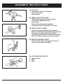
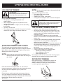
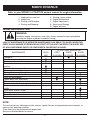
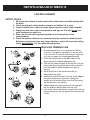
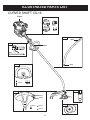
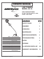
OWNERS MANUAL
LINE TRIMMER
MODEL CS-16
SARLO MANUFACTURING
POWERED BY
CONTENTS
™
Model
Shaft style
Shaft length
Engine
Cutting width
Line size
Unit weight
Head type
Starting system
Handle type
Clutch
Shoulder harness
Warranty
P.O. BOX 1169 FORT MYERS, FL 33902
PHONE: 1-800-749-5296
CS-16 String Trimmer
Curved
56"
34cc 4-cycle
Briggs & Stratton
16"
.095"/2.4 mm
12.8 lbs
Bump feed
Easy starting 4-cycle
Standard loop
No
No
2 year Consumer
90 day Commercial
This unit is intended for occasional use.
PAGE
SAFETY RULES
1
ASSEMBLY
2
OPERATION
3
MAINTENANCE
4
SERVICE/ADJUSTMENTS
5
TROUBLESHOOTING
6
NOTES
6
STORAGE
7
ILLUSTRATED PARTS LIST
8-9
WARRANTY INFORMATION
10
P/N 10006 12/03
RULES FOR SAFE OPERATION
SAFETY AND INTERNATIONAL SYMBOLS
This operator’s manual describes safety and international symbols and pictographs that
appear on this product. Read the operator’s manual for complete safety, assembly, operating,
maintenance and repair information.
SYMBOL
MEANING
• SAFETY ALERT SYMBOL
Indicates danger, warning or caution. May be used in
conjunction with other symbols or pictographs.
• WARNING - READ OPERATOR’S MANUAL
Read the operator’s manual(s) and follow all warnings and
safety instructions. Failure to do so can result in serious
injury to the operator and/or bystanders.
• WEAR EYE AND HEARING PROTECTION
WARNING: Thrown objects and loud noise can cause severe
eye injury and hearing loss. Wear eye protection meeting ANSI
Z87.1 standards and ear protection when operating this unit.
Use a full face shield when needed.
• KEEP BYSTANDERS AWAY
WARNING: Keep all bystanders, especially children and pets,
at least 50 feet (15m) from the operating area.
• THROWN OBJECTS AND ROTATING CUTTER CAN
CAUSE SEVERE INJURY
WARNING: Do not operate without the cutting attachment
shield in place. Keep all from the rotating cutting attachment.
WARNING: Never use blades or flailing devices. This unit is
designed for line trimmer use only. Use of any other
accessories or attachments will increase the risk of injury.
SAFETY RULES
• Do not allow a person to use this unit unless instructions are read and understood. Never
allow children to operate or play with the unit.
• Do not operate this unit when tired, ill or under the influence of alcohol, drugs, or medication.
• Always wear heavy, long pants, boots, gloves, and a long sleeve shirt. Do not wear loose
clothing, jewelry, short pants, sandals, or go barefoot. Secure hair so it is above
shoulder level.
• Inspect unit before each use. Replace damaged parts. Check for fuel leaks. Make sure all
fasteners are in place and secure. Replace cutting attachment parts that are cracked,
chipped, or damaged in any way. Make sure the cutting attachment is properly installed and
securely fastened. Be sure the cutting attachment shield is properly attached, and in the
position recommended by the manufacturer. Use only flexible, non-metallic line
recommended by the manufacturer. Never use, for example, wire or wire-rope which can
break off and become a dangerous projectile.
• Keep firm footing and balance. Do not over-reach. Keep cutting attachment below waist
level. Keep all parts of your body away from the rotating cutting attachment and hot
surfaces.
• Never start or run the unit inside a closed room or building; breathing exhaust fumes can kill.
• Pour fuel outdoors where there are no sparks and flames. Slowly remove the fuel cap only
after stopping the engine. Do not smoke while fueling. Wipe spilled fuel from the unit. Move
at least 10 ft. (3 m) away from the fueling source and site before starting engine.
• Clear the area to be cut before each use. Remove all objects such as rocks, broken glass,
nails, wire, or string which can be thrown or become entangled in the cutting attachment.
Clear the area of children, bystanders and pets. At a minimum, keep all children, bystanders
and pets outside a 50 ft. (15 m) radius; outside the 50 ft. zone, there is still a risk of injury
to bystanders from being struck with the moving strings in the event of a cutting lines
thrust or other unexpected reaction of the saw.
• The cutting attachment may be spinning during carburetor adjustments. Wear your
protective equipment and observe all safety instructions. When the unit is turned off make
sure the cutting attachment has stopped before the unit is set down.
• The handles and shield must be mounted according to the instructions. The unit is
designed to be used while positioned on the right side.
1
ASSEMBLY INSTRUCTIONS
■
•
•
•
TOOL LIST
Screwdriver (Phillips or Standard)
Allen wrench 4mm
10mm wrench
■ INSTALLING CUTTING HEAD
• While locking the gear shaft by inserting
a pin into the upper holder and
the housing.
• Rotate the cutting head to clockwise
to engage threads. Hand-tighten it securely.
■ INSTALL ASSIST HANDLE
• Use the 3 screws provided for this assembly.
Mount the back edge of the handle clamp to match
the arrow on the tube. Adjust the handle for
comfort and good balance. Check that the cutting
line of the unit is away from your feet and legs.
■ INSTALLING DEBRIS GUARD
• Put the debris guard on the gear box, attach it
with the screw and nut provided.
■
1.
2.
3.
3
2
STOP AND START SWITCH
Ignition switch
Stop
Start
1
2
OPERATING INSTRUCTIONS
HOLDING THE TRIMMER
NOTE: Do not rest the bump head on the ground while the
unit is running.
Some line breakage will occur from:
•
Entanglement with foreign matter
•
Normal line fatigue
•
Attempting to cut thick, stalky weeds
•
Forcing the line into objects such as walls or fence posts.
WARNING: Always wear eye, hearing,
foot and body protection to reduce the
risk of injury when operating this unit
Before operating the unit, stand in the operating position
(Fig. 1). Check for the following:
•
The operator is wearing eye protection and
proper clothing.
•
With a slightly-bent right arm, the operator’s hand is
holding the shaft grip.
•
The operator’s left arm is straight, the left hand holding
the D-handle
•
The unit is at waist level
•
The cutting attachment is parallel to the ground and easily
contacts the grass without the need to bend over.
CAUTION: Do not remove or alter the line
cutting blade assembly. Excessive line length
will overload the engine and could cause
damage to the engine.
TIPS FOR BEST TRIMMING RESULTS
•
•
Keep the cutting attachment parallel to the ground.
Do not force the cutting attachment. Allow the tip of the
line to do the cutting, especially along walls. Cutting with
more than the tip will reduce cutting efficiency and may
overload the engine.
•
Cut grass over 8 in. (200 mm) by working from top to
bottom in small increments to avoid premature line wear or
engine drag.
•
Cut from right to left whenever possible. Cutting to the left
improves the unit’s cutting efficiency. Clippings are
thrown away from the operator.
•
Slowly move the trimmer into and out of the cutting area at
the desired height. Move either in a forward-backward or
side-to-side motion. Cutting shorter lengths produces the
best results.
•
Trim only when grass and weeds are dry.
•
The life of your cutting line is dependent upon:
• Following the trimming techniques
• What vegetation is being cut
• Where vegetation is cut
For example, the line will wear faster when trimming against
foundation wall as opposed to trimming around a tree.
™
Fig. 1
ADJUSTING TRIMMING LINE LENGTH
The bump head cutting attachment allows you to release
trimming line without stopping the engine. To release more line,
lightly tap the cutting attachment on the ground (Fig. 2) while
operating the trimmer at high speed.
NOTE: Always keep the trimming line fully extended. Line
release becomes more difficult when the cutting line
gets shorter.
DECORATIVE TRIMMING
Decorative trimming is accomplished by removing all
vegetation around trees, posts, fences and more.
Rotate the whole unit so that the cutting attachment
is at 30° angle to the ground (Fig. 3)
Fig. 2
Each time the head is bumped, about 1 in. (25.4 mm) of
trimming line releases. A blade in the cutting attachment shield
will cut the line to the proper length if any excess line
is released.
For best results, tap the bump knob on bare ground or hard
soil. If you attempt a line release in tall grass, the engine may
stall. Always keep the trimming line fully extended. Line release
becomes more difficult when the cutting line
gets shorter.
Fig. 3
3
MAINTENANCE
Refer to your BRIGGS & STRATTON owners’ manual for engine information
1.
2.
3.
4.
Adding oil to a new unit
Adding fuel
Starting a NEW engine
Starting and Stopping
5.
6.
7.
8.
9.
Starting a warm engine
Engine Maintenance
Engine Adjustments
Service and Storage
Engine Warranty
Periodic Maintenance Chart
WARNING:
Accidental engine starting can cause injury. Always remove the spark plug before
servicing the engine to prevent accidental starting.
LACK OF MAINTENANCE OR IMPROPER MAINTENANCE CAN RESULT IN INJURY. MODIFYING
PARTS IN ANY MANNER OR REMOVING ANY PART OF THIS UNIT CAN RESULT IN INJURY. USE
OF NON-CONFORMING PARTS OR COMPONENTS CAN RESULT IN INJURY.
MAINTENANCE
Change oil*
Check and replenish fuel
Check and replenish oil
Check bolts, nuts and screws for looseness
and loss
Check throttle lever operation
Check engine switch operation
Check guard assembly condition
Clean/replace in-tank fuel filter
Clean air filter element
Tighten bolts, nuts and screws
Clean spark plug and adjust electrode gap
Remove dust and dirt from cylinder fins
Remove carbon deposits in the exhaust
muffler
Clean spark arrester screen
Check gear case assembly lubrication
Check drive shaft lubrication
Check valve clearance
EACH
USE
n
n
AFTER EVERY SEASON OR
FIRST
EVERY
EVERY
10 HOURS
25 HOURS
50 HOURS
n*
n
n
n
n
n
n
*Change engine oil after first 4 hours of use. Please refer to the engine manual for more details.
n
n
n
n
n
n
n
n
n
NOTE:
The service intervals indicated are to be used as a guide. Service to be performed more frequently as
necessary by operating condition.
These items must be performed with proper tools.
See your authorized dealer for service.
4
SERVICE/ADJUSTMENTS
LINE REPLACEMENT
SAFETY RULES
1. Shut down the trimmer to make certain the head cannot turn while working with
the head.
2. Check mounting of cutting head on trimmer and tighten if it is loose
3. Inspect head for wear, chips or cracks. Replace parts or entire head if needed.
4. Always use line that is the correct diameter and type for this unit. Do not use
metal reinforced or metal line.
5. Make sure the two retaining pawls spread out to the periphery of the
cover windows.
6. Check the head for deflection or abnormal noise by rotating the head by hand.
Deflection or abnormal noise may cause vibrations, which will cause the cutting
line to weld together. It is also potentially dangerous.
REFILLING TRIMMING LINE
1. For replacement line, use a diameter of .095 in.
(2.4 mm). The spool is capable for a line up to 20
ft. (6 m) on the 4 in. head. Avoid using a larger line
as it may cut down the trimming performance.
2. Pinch the slotted area on the both sides of the
spool housing to unhook the bottom cap.
3. Take out the spool and pull off the old line. Put one
end of new line through the spool holes and pull it
until the length is equal between each part of
the line.
4. Wind up the line in the correct direction as
indicated on the spool.
5. Hook each end of the line in the slot on the edge of
the spool, and then put the ends through the
eyelets on the housing. Make sure that the spring
and the washers are in place.
6. While holding the spool against the housing, pull
the line ends to release them from the slot.
7. Line up the slot on the bottom cap with the hook on
the housing, press the cap against the housing until
it clicks.
5
TROUBLESHOOTING GUIDE
Case 1. Starting failure
CHECK
Fuel tank
Fuel filter
Carburetor idle speed screw
No spark
PROBABLE CAUSES
➔
➔
➔
➔
➔
Spark plug
➔
Incorrect fuel
Fuel filter is clogged
Out of normal range
Spark plug is fouled/wet
Plug gap is incorrect
Disconnected
ACTION
➔
➔
➔
➔
➔
➔
Drain it and fill with correct fuel
Clean
Adjust to normal range
Clean/dry
[Correct GAP .025" (0.6~0.7 mm)]
Retighten
Case 2. Engine starts but does not keep running/Hard re-starting
CHECK
Fuel tank
Carburetor idle speed screw
Muffler, cylinder(exhaust port)
Air cleaner
Cylinder fin, fan cover
PROBABLE CAUSES
➔
➔
➔
➔
➔
Incorrect fuel or stale fuel
Out of normal range
Carbon is built-up
Clogged with dust
Clogged with dust
ACTION
➔
➔
➔
➔
➔
Drain it and fill with correct fuel
Adjust to normal range
Wipe away
Wash
Clean
If your unit needs further service, please consult with an authorized service dealer in your area.
NOTES
6
STORAGE
WARNING: Perform the following steps after each use:
• Allow engine to cool, and secure the unit before storing or transporting.
• Store unit and fuel in a well ventilated area where fuel vapors cannot reach sparks or open flames form
water heaters, electric motors or switches, furnaces, etc.
• Store unit with all guards in place. Position unit so that any sharp objects cannot accidentally cause injury.
• Store unit and fuel well out of the reach of children.
SEASONAL STORAGE
Prepare unit for storage at end of season or if it will not be used for 30 days or more. If your unit is to be
stored for a period of time:
• Drain all fuel from the fuel tank into the proper receptacles for storage.
• Press purge bulb 15 times to remove all fuel from carburetor and fuel lines. Drain this fuel into proper
receptacles. If fuel is to be disposed, please refer to local rules for proper disposal.
• Clean the entire unit before lengthy storage.
• Store in a clean dry area.
• Lightly oil external metal surfaces.
• This trimmer may be stored in a variety of positions. If possible, it is preferred to store the trimmer in a
horizontal position with the spark plug up. The trimmer should not be stored or transported with the
spark plug down.
• Storing or transporting the trimmer with the spark plug down may result in white smoke coming from the
muffler or difficulty starting.
FUEL SYSTEM
Fuel stabilizer is an acceptable alternative in minimizing the formation of fuel gum deposits during storage.
Add stabilizer to the gasoline in the fuel tank or fuel storage container. Follow the mix instructions found on
stabilizer container. Run engine at least 5 minutes after adding stabilizer.
ENGINE
• Remove spark plug and pour 1 teaspoon of HD30 wt. engine oil through the spark plug opening. Slowly
pull the starter rope 8 to 10 times to distribute oil.
• Replace spark plug with new one of recommended type and heat range.
• Clean air filter
• Check entire unit for loose screws, nuts, and bolts. Replace any damaged, broken, or worn parts.
• At the beginning of the next season, use only fresh fuel.
OTHER
• Do not store gasoline from one season to another.
• Replace your gasoline can if it starts to rust.
• When removing the unit from storage, only use fresh gasoline. Perform the routine operation checks as
spelled out in the manual before any start.
7
ILLUSTRATED PARTS LIST
CURVED SHAFT CS-16
Engine
10014
10017
™
10015
10016
10200
10002
10032
10000
10041
10210
10231
10236
10235
10211
10212
10221
10220
10237
10222
10238
10239
8
ILLUSTRATED PARTS LIST
CURVED SHAFT CS-16
Part Number
Model Used On
Quantity
10000
10002
10006
10014
10015
10016
10017
10032
10041
10200
10210
10211
10212
10220
10221
10222
10231
10235
10236
10237
10238
10239
ENGINE
BC-8/SS-18/CS-16
SS-18/CS-16
CS-16
CS-16/SS-18/BC-8
CS-16/SS-18/BC-8
CS-16/SS-18/BC-8
CS-16/SS-18/BC-8
SS-18/CS-16
SS-18/CS-16
CS-16
CS-16
CS-16
CS-16
CS-16
CS-16
CS-16
CS-16
SS-18/CS-16
SS-18/CS-16
CS-16
CS-16
CS-16
SS-18/CS-16
1
1
1
1
1
2
1
1
1
1
1
1
1
1
1
1
1
3
3
1
1
1
1
Description
Decal for pipe
Label
Owner's manual
Nose cone A
Nose cone B
Nose cone screw
Engine clamp assy.
Single type lever
Cable, throttle
Pipe assy
Cooling type flexible shaft
Two bearing head case
Protector assy
Blade to cut nylon code
Screw for the cutter
Tap and go with dia. 0.095"
Handle assy
Screw for loop handle
Nut for loop handle
Bolt for guard
Nut for guard
Washer for clamp bolt
34cc 4-cycle Briggs & Stratton, Model 21032 0118 E1
WARNING: IT IS UNSAFE TO USE ANY AFTER MARKET HEAD, ATTACHMENT, ACCESSORY
OR BLADE ON THIS UNIT. USE ONLY HEADS, ATTACHMENTS, BLADES AND ACCESSORIES
MANUFACTURED BY SARLO AND INTENDED FOR THIS SPECIFIC MODEL.
9
WARRANTY
SARLO MANUFACTURING, INC. hereby warrants to the original retail purchaser ALL NEW
products of its own manufacture to be free from defect in material and workmanship, for a period of
two (2) years form the date of the original purchase, subject to the following exceptions.
Products
Hand Held String Trimmers
Consumer Use
2 Years
Commercial/Rental Use
90 Days
•
No warranty is extended to any equipment, which has been misused, neglected, or
damaged by accident. Sarlo shall not be responsible for damage in transit or
handling by any common carrier. Under no circumstances, within or without the
warranty period, will the company be liable for damage for loss, or damage resulting
from delay, or any consequential damage including but not limited to any cost or
expense of providing substitute equipment or service during periods of malfunction
or non-use. Sarlo will repair or replace, free of charge any part or parts of the units
found upon examination by any Factory Authorized Dealer or by the factory to be
defective in materials and or workmanship for the term of the warranty.
•
The consumer is responsible for: (1) normal maintenance such as greasing, gear
case lubrication, minor adjustment and (2) transportation of any Sarlo product to and
from the place warranty work is performed.
•
Sarlo warranty WILL NOT APPLY to any products repaired or altered by anyone other
than an Authorized Service Distributor or Authorized Service Dealer.
•
Sarlo reserves the right to incorporate any changes in design into its products
without obligation to make changes on units previously manufactured.
•
For engine warranty, please refer to the Briggs & Stratton manual.
10