1
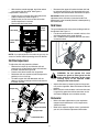
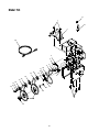
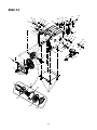
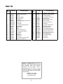
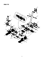
Operator’s Manual
SNOW THROWER
MODEL 31AH7S3G701
IMPORTANT: READ SAFETY RULES AND INSTRUCTIONS CAREFULLY
Warning: This unit is equipped with an internal combustion engine and should not be used on or near any unimproved forestcovered, brush-covered or grass-covered land unless the engine’s exhaust system is equipped with a spark arrester meeting
applicable local or state laws (if any). If a spark arrester is used, it should be maintained in effective working order by the operator.
In the State of California the above is required by law (Section 4442 of the California Public Resources Code). Other states may have
similar laws. Federal laws apply on federal lands. A spark arrester for the muffler is available through your nearest engine authorized
service dealer or contact the service department, P.O. Box 361131 Cleveland, Ohio 44136-0019.
MTD LLC P.O. BOX 361131 CLEVELAND, OHIO 44136-0019
PRINTED IN U.S.A.
FORM NO. 770-10021G.fm
(5/05)
TABLE OF CONTENTS
Content
Important Safe Operation Practices
Assembling Your Snow Thrower
Know Your Snow Thrower
Operating Your Snow Thrower
Adjusting Your Snow Thrower
Page
3
5
6
8
10
Content
Maintaining Your Snow Thrower
Servicing Your Snow Thrower
Trouble Shooting
Illustrated Parts List
Warranty
Page
12
13
16
18
28
FINDING MODEL NUMBER
This Operator’s Manual is an important part of your new snow thrower. It will help you assemble, prepare
and maintain the unit for best performance. Please read and understand what it says.
Before you start assembling your new equipment, please locate the model plate on the
equipment and copy the information from it in the space provided below. A sample model plate is
also given below. You can locate the model plate by looking at the lower frame cover on the rear
of your snow thrower. This information will be necessary to use the manufacturer’s
web site and/or help from the Customer Support Department or an authorized service dealer.
Copy the model number here:
www.yardman.com
MTD LLC
P. O. BOX 361131
CLEVELAND,OH 44136
330-220-4683
800-800-7310
Copy the serial number here:
CUSTOMER SUPPORT
Please do NOT return the unit to the retailer from where it was purchased, without first contacting Customer Support.
If you have difficulty assembling this product or have any questions regarding the controls, operation or
maintenance of this unit, you can seek help from the experts. Choose from the options below:
Visit yardman.com for many useful suggestions. Click on the Customer Support menu option.
If you prefer to reach a Customer Support Representative, please call 1-800-800-7310.
Engine
Manual
The engine manufacturer is responsible for all engine-related issues with regards to
performance, power-rating, specifications, warranty and service. Please refer to the engine
manufacturer’s Owner’s/Operator’s Manual, packed separately with your unit, for more
information.
2
SECTION 1: IMPORTANT SAFE OPERATION PRACTICES
WARNING: This symbol points out important safety instructions which, if not followed, could endanger
the personal safety and/or property of yourself and others. Read and follow all instructions in this manual
before attempting to operate this machine. Failure to comply with these instructions may result in
personal injury. When you see this symbol—heed its warning.
WARNING: Engine Exhaust, some of its constituents, and certain vehicle components contain
or emit chemicals known to the State of California to cause cancer, birth defects or other
reproductive harm.
DANGER: This machine was built to be operated according to the rules for safe operation in this
manual. As with any type of power equipment, carelessness or error on the part of the operator can
result in serious injury. This machine is capable of amputating hands and feet and throwing objects.
Failure to observe the following safety instructions could result in serious injury or death.
TRAINING
1.
2.
3.
4.
5.
6.
7.
7.
Read, understand, and follow all instructions on the
machine and in the manual(s) before attempting to
assemble and operate. Keep this manual in a safe place
for future and regular reference and for ordering
replacement parts.
Be familiar with all controls and their proper operation.
Know how to stop the machine and disengage them
quickly.
Never allow children under 14 years old to operate this
machine. Children 14 years old and over should read and
understand the operation instructions and safety rules in
this manual and should be trained and supervised by a
parent.
Never allow adults to operate this machine without
proper instruction.
Thrown objects can cause serious personal injury. Plan
your snow-throwing pattern to avoid discharge of material
toward roads, bystanders and the like.
Keep bystanders, helpers, pets and children at least 75
feet from the machine while it is in operation. Stop
machine if anyone enters the area.
Exercise caution to avoid slipping or falling, especially
when operating in reverse.
8.
9.
PREPARATION
1.
2.
3.
4.
5.
6.
Thoroughly inspect the area where the equipment is to
be used. Remove all doormats, newspapers, sleds,
boards, wires and other foreign objects, which could be
tripped over or thrown by the auger/impeller.
Always wear safety glasses or eye shields during
operation and while performing an adjustment or repair to
protect your eyes. Thrown objects which ricochet can
cause serious injury to the eyes.
Do not operate without wearing adequate winter outer
garments. Do not wear jewelry, long scarves or other
loose clothing, which could become entangled in moving
parts. Wear footwear which will improve footing on
slippery surfaces.
Use a grounded three-wire extension cord and
receptacle for all units with electric start engines.
Adjust collector housing height to clear gravel or crushed
rock surfaces.
Disengage all clutch levers before starting the engine.
Never attempt to make any adjustments while engine is
running, except where specifically recommended in the
operator’s manual.
Let engine and machine adjust to outdoor temperature
before starting to clear snow.
To avoid personal injury or property damage use extreme
care in handling gasoline. Gasoline is extremely
flammable and the vapors are explosive. Serious
personal injury can occur when gasoline is spilled on
yourself or your clothes, which can ignite. Wash your skin
and change clothes immediately.
a. Use only an approved gasoline container.
b. Extinguish all cigarettes, cigars, pipes and other
sources of ignition.
c. Never fuel machine indoors.
d. Never remove gas cap or add fuel while the
engine is hot or running.
e. Allow engine to cool at least two minutes before
refueling.
f. Never over fill fuel tank. Fill tank to no more than
½ inch below bottom of filler neck to provide space
for fuel expansion.
g. Replace gasoline cap and tighten securely.
h. If gasoline is spilled, wipe it off the engine and
equipment. Move machine to another area. Wait 5
minutes before starting the engine.
i. Never store the machine or fuel container inside
where there is an open flame, spark or pilot light
(e.g. furnace, water heater, space heater, clothes
dryer etc.).
j. Allow machine to cool at least 5 minutes before
storing.
OPERATION
1.
2.
3.
4.
3
Do not put hands or feet near rotating parts, in the auger/
impeller housing or chute assembly. Contact with the
rotating parts can amputate hands and feet.
The auger/impeller control is a safety device. Never
bypass its operation. Doing so makes the machine
unsafe and may cause personal injury.
The controls must operate easily in both directions and
automatically return to the disengaged position when
released.
Never operate with a missing or damaged chute
assembly. Keep all safety devices in place and working.
5.
6.
7.
8.
9.
10.
11.
12.
13.
14.
15.
16.
17.
18.
19.
20.
MAINTENANCE AND STORAGE
Never run an engine indoors or in a poorly ventilated
area. Engine exhaust contains carbon monoxide, an
odorless and deadly gas.
Do not operate machine while under the influence of
alcohol or drugs.
Muffler and engine become hot and can cause a burn. Do
not touch.
Exercise extreme caution when operating on or crossing
gravel surfaces. Stay alert for hidden hazards or traffic.
Exercise caution when changing direction and while
operating on slopes.
Plan your snow-throwing pattern to avoid discharge
towards windows, walls, cars etc. Thus, avoiding possible
property damage or personal injury caused by a ricochet.
Never direct discharge at children, bystanders and pets
or allow anyone in front of the machine.
Do not overload machine capacity by attempting to clear
snow at too fast of a rate.
Never operate this machine without good visibility or light.
Always be sure of your footing and keep a firm hold on
the handles. Walk, never run.
Disengage power to the auger/impeller when
transporting or not in use.
Never operate machine at high transport speeds on
slippery surfaces. Look down and behind and use care
when in reverse.
If the machine should start to vibrate abnormally, stop the
engine, disconnect the spark plug wire and ground it
against the engine. Inspect thoroughly for damage.
Repair any damage before starting and operating.
Disengage all controls and stop engine before you leave
the operating position (behind the handles). Wait until the
auger/impeller comes to a complete stop before
unclogging the chute assembly, making any adjustments,
or inspections.
Never put your hand in the discharge or collector
openings. Always use the clean-out tool provided to
unclog the discharge opening. Do not unclog chute
assembly while engine is running.Shut off engine and
remain behind handles until all moving parts have
stopped before unclogging.
Use only attachments and accessories approved by the
manufacturer (e.g. wheel weights, tire chains, cabs etc.).
If situations occur which are not covered in this manual,
use care and good judgment. Contact your dealer or
telephone 1-800-800-7310 for assistance and the name
of your nearest servicing dealer.
1.
Never tamper with safety devices. Check their proper
operation regularly. Refer to the maintenance and
adjustment sections of this manual.
2. Before cleaning, repairing, or inspecting machine
disengage all controls and stop engine. Wait until the
auger/impeller come to a complete stop. Disconnect the
spark plug wire and ground against the engine to prevent
unintended starting.
3. Check bolts and screws for proper tightness at frequent
intervals to keep the machine in safe working condition.
Also, visually inspect machine for any damage.
4. Do not change the engine governor setting or over-speed
the engine. The governor controls the maximum safe
operating speed of the engine.
5. Snow thrower shave plates and skid shoes are subject to
wear and damage. For your safety protection, frequently
check all components and replace with original
equipment manufacturer’s (OEM) parts only. “Use of
parts which do not meet the original equipment
specifications may lead to improper performance and
compromise safety!”
6. Check clutch controls periodically to verify they engage
and disengage properly and adjust, if necessary. Refer to
the adjustment section in this operator’s manual for
instructions.
7. Maintain or replace safety and instruction labels, as
necessary.
8. Observe proper disposal laws and regulations for gas, oil,
etc. to protect the environment.
9. Prior to storing, run machine a few minutes to clear snow
from machine and prevent freeze up of auger/impeller.
10. Never store the machine or fuel container inside where
there is an open flame, spark or pilot light such as a water
heater, furnace, clothes dryer etc.
11. Always refer to the operator’s manual for proper
instructions on off-season storage.
WARNING: Restrict the use of this power
machine to persons who read, understand
and follow the warnings and instructions
in this manual and on the machine.
4
SECTION 2: ASSEMBLING YOUR SNOW THROWER
•
NOTE: References to right or left side of the snow
thrower are determined from behind the unit in the
operating position. The “operator’s position” is defined
as standing directly behind the snow thrower, facing the
handle panel.
•
•
Unpacking
•
•
•
•
•
Remove screws from the top sides and ends of the
shipping crate.
Set panel aside to avoid tire punctures or personal
injury.
Remove and discard plastic bag that covers unit.
Remove any loose parts included with unit (i.e.,
Operator’s Manual, etc.).
Roll unit out of crate.
Raise the upper handle assembly until it locks over
the lower handle.
Look at the lower rear of snow thrower frame to be
sure both cables are aligned with cable roller
guides.
Secure the upper handle and lower handle with the
two plastic wing knobs, cupped washers and
carriage bolts previously removed and tighten the
upper two plastic wing knobs. See Figure 3.
Upper
Chute
Rod
Bracket
Carriage
Bolt
Cupped
Washer
Loose Parts
The augers are secured to the auger shaft with two
shear pins and cotter pins. If you hit a foreign object or
ice jam, the snow thrower is designed so that the pins
may shear. Two replacement shear pins and cotter pins
are provided for your convenience. Store in a safe
place until needed. See Figure 1.
Upper
Chute
Rod
Wing
Nut
Shear Pins
Shift Rod
Connector
Hairpin Clip
Cotter
Pins
Carriage Bolt
Figure 1
Lower Chute Rod
Assembly
Figure 3
WARNING: Disconnect the spark plug
wire and ground it against the engine to
prevent unintended starting.
•
•
Remove the lower two plastic wing knobs, cupped
washers and carriage bolts from each side of the
lower handle. See Figure 2.
Lower
Handle
Slide the shift rod connector down over the end of
the lower shift rod. Tap the connector until it locks
on the lower shift rod. See Figure 3.
NOTE: If the connector is not properly assembled, the
shift rod will pivot and you will not be able to change
speeds or change directions.
Handle
Panel
Attaching Chute Directional Control
•
•
Upper Handle
Wing Knobs,
Washers, & Bolts
Figure 2
5
Remove the hairpin clip from the upper chute rod
and slide the upper chute rod through the upper
chute rod bracket and into the lower chute rod. A
pair of pliers may help in this job.
Align the two holes on both chute rods and insert
the hairpin clip removed earlier, through these
holes. See Figure 3.
•
•
If not already attached, slip the cables that run from
the handle panel to the chute into the cable guide
located on top of the engine. See Figure 4.
Unwrap the headlight wire, which is attached to the
headlight beneath the handle panel.
Wind the headlight wire around the right handle
until excess slack is removed.
Plug the wire from the headlight into the wire lead
coming from the right side of the engine, beneath
the fuel tank.
•
Cable Guide
•
Figure 4
SECTION 3: KNOW YOUR SNOW THROWER
Drive Control /
Auger Control Lock
Shift Lever
Chute Tilt
Control
Heated Handles
Switch
Clean-out
Tool
Auger Control
Headlight
Chute
Assembly
Track Steering
Control
Electric
Starter
Button
Primer
Chute Directional
Control
Auger
Switch
Box
Choke
Safety
Ignition Key
Skid Shoe
Throttle
Control
Recoil
Starter
Handle
Figure 5
WARNING: Read, understand, and follow
all instructions and warnings on the
machine and in this manual before
operating.
IMPORTANT: Always release drive control before
changing speeds.
Auger Control
The auger control is located on the left handle.
Squeeze the auger control to engage the augers.
Release to stop the snow throwing action. (Drive
control must also be released.) See Figure 5.
Drive Control / Auger Control Lock
The drive control is located on the right handle.
Squeeze the drive control to engage the wheel drive.
Release to stop. See Figure 5.
IMPORTANT: Refer to Auger Control Test on page 9 prior to
The drive control also locks the auger control so you
can turn the chute directional control without
interrupting the snow throwing process. If the auger
control is engaged along with the drive control, the
operator can release the auger control (on the left
handle) and the augers will remain engaged. Release
both controls to stop the augers and track drive.
operating your snow thrower. Read and follow all
instructions carefully and perform all adjustments to
verify your snow thrower is operating safely and
properly.
6
Chute Tilt Control
NOTE: It is easier to maneuver a non-running snow
thrower with both track steering controls held in
simultaneously.
The distance snow is thrown can be changed by
adjusting the angle of the upper chute. Move the chute
tilt control forward to decrease the distance, and
backwards to increase distance. See Figure 5.
Throttle Control
The throttle control is located on the engine. It regulates
the speed of the engine and will shut off the engine
when pushed down completely. See Figure 5.
Skid Shoe
The space between the shave plate and the ground can
be adjusted by positioning the skid shoes. Refer to Skid
Shoe Adjustment on page 11.
Safety Ignition Key
The safety ignition key must be fully inserted and
snapped in place before the unit will start. Remove the
ignition key to prevent unauthorized use of equipment.
See Figure 5.
Shift Lever
The shift lever is located in the center of the handle
panel and is used to determine both ground speed and
direction of travel. It can be moved into any of eight
positions. See Figure 5.
IMPORTANT: Do NOT attempt to turn the key.
Headlight
Forward
The headlight is on whenever the engine is running.
Your snow thrower has six forward (F) speeds, with
position number one (1) being the slowest speed.
Track Lock Lever
Reverse
Your snow thrower has two reverse (R) speeds, with
position number one (1) being the slowest speed.
The track lock lever is located on the right side of the
snow thrower and is used to select the position of the
auger housing and the method of track operation. Move
the lever to the right, then forward or backward to one of
the three positions. See Figure 6.
IMPORTANT: Always release drive control before
changing speeds.
Transport: Raises the front end of the snow thrower for
Chute Directional Control
The chute directional control is located on left side of
the snow thrower. See Figure 5.
easy transport. Using proper caution, this position may
also be used on many gravel driveways to clear snow
while leaving gravel undisturbed.
To change the direction in which snow is thrown, turn
chute directional control as follows:
Normal Snow: Allows the tracks to be suspended
•
•
independently for continuous ground contact.
Crank clockwise to discharge to the left.
Crank counterclockwise to discharge to the right.
Packed Snow: Locks the front end of the snow thrower
down to the ground for hard-packed or icy snow
conditions.
Heated Handles Switch
Track Lock
Lever
This switch is located on the right side of the snow
thrower dash panel. To activate the heated handles,
toggle the switch to the right to generate heat within the
handle grips. Toggle the switch to the left to the OFF
position after using the snow thrower. See Figure 5.
Packed
Snow
NOTE: The heated handles grips are a compliment to,
not a substitute for, proper cold weather outerwear for
the operator’s hands. It is recommended that the snow
thrower operator wear gloves/mittens to avoid
extremities of winter while operating this equipment.
Track Steering Controls
Normal
Snow
The left and right track steering controls are located on
the underside of the handles and they are used to
assist in steering the snow thrower. Squeeze the right
track control when turning right, squeeze the left control
when turning left. Operate your snow thrower in open
areas until you become familiar with these controls.
See Figure 5.
Transport
Figure 6
7
SECTION 4: OPERATING YOUR SNOW THROWER
Before Starting
•
WARNING: Read, understand, and follow
all instructions and warnings on the
machine and in this manual before
operating.
•
•
Gas And Oil Fill-up
•
Service the engine with gasoline and oil as
instructed in the separate engine manual packed with
your snow thrower. Read instructions carefully.
•
WARNING: Use extreme care when
handling gasoline. Gasoline is extremely
flammable and the vapors are explosive.
Never fuel machine indoors or while the
engine is hot or running. Extinguish
cigarettes, cigars, pipes an other sources
of ignition.
•
•
•
A plastic cup may be provided inside the fuel fill
opening to protect the tank during manufacturing.
Remove and discard. Use the threaded fuel tank
cap to close after fill-up.
•
Recoil Starter
•
To Start Engine
•
•
•
Attach spark plug wire to spark plug. Make certain
the metal loop on end of the spark plug wire (inside
the boot) is fastened securely over the metal tip on
the spark plug.
Make certain the auger and drive controls are in the
disengaged (up) position.
Move throttle control up to FAST position. Insert
ignition key into slot and snap in place. See Figure
5. Do not turn key.
•
•
•
Electric Starter
•
•
Rotate choke knob to FULL choke position (cold
engine start). If engine is warm, place choke in OFF
position instead of FULL.
Push primer button two or three times. If engine is
warm, push primer button once only.
NOTE: Always cover vent hole in primer button when
pushing. Additional priming may be necessary for first
start if temperature is below 15°F.
NOTE: Engine will not start unless ignition key is
inserted into ignition slot in carburetor cover.
•
If your home electrical system is grounded, but a
three-hole receptacle is not available, one should
be installed by a licensed electrician before using
the electric starter.
If you have a grounded three-prong receptacle,
proceed as follows:
Move engine speed control to “Fast” position and
set Choke Control to “Full” position.
Push Primer three (3) times, making sure to cover
vent hole when pushing.
Connect power cord to switch box on engine. Plug
the other end of power cord into a three-hole,
grounded 120 volt AC receptacle.
Push starter button on top of the engine to crank
engine. As you crank the engine, move choke knob
to FULL choke position.
When engine starts, release starter button, and
move choke gradually to OFF. If engine falters,
move choke immediately to FULL and then
gradually to OFF.
When disconnecting the power cord, always unplug
from the three-prong receptacle first and then from
the snow thrower.
Determine that your house wiring is a three-wire
grounded system. Ask a licensed electrician if you
are not certain.
If your house wiring system is not a three-wire
grounded system, do not use this electric starter
under any conditions.
Grasp starter handle and pull rope out slowly, until
it pulls slightly harder. Let rope rewind slowly.
Pull starter handle rapidly. Do not allow handle to
snap back. Allow it to rewind slowly while keeping a
firm hold on the starter handle.
Repeat the previous steps until engine starts.
To Stop Engine
•
•
WARNING: The electric starter is
equipped with a grounded three-wire
power cord and plug and is designed to
operate on 120 volt AC household
current. It must be used with a properly
grounded three-prong receptacle at all
times to avoid the possibility of electric
shock. Follow all instructions carefully
prior to operating the electric starter.
Run engine for a few minutes before stopping to
help dry off any moisture on the engine.
To help prevent possible freeze-up of starter,
proceed as follows:
Electric Starter:
•
8
Connect power cord to switch box on engine, then
to 120 volt AC receptacle. With the engine running,
push starter button and spin the starter for several
seconds. The unusual sound made by spinning the
starter will not harm engine or starter. Disconnect
the power cord from receptacle first, and then from
switch box.
Recoil Starter
IMPORTANT: If the auger shows ANY signs of rotating,
•
immediately return to the operator’s position and shut
off the engine. Wait for ALL moving parts to stop before
re-adjusting the auger control.
•
•
With engine running, pull starter rope with a rapid,
continuous full arm stroke three or four times.
Pulling the starter rope will produce a loud clattering
sound, which is not harmful to the engine or starter.
To stop engine, move throttle control to “stop” or
“off” position.
Remove ignition key (DO NOT turn key) to prevent
unauthorized use of equipment.
•
•
•
•
NOTE: Do not lose ignition key. Keep it in a safe place.
Engine will not start without ignition key.
•
Wipe all snow and moisture from the carburetor
cover in the area of the control levers. Also, move
control levers back and forth several times.
To readjust the control cable, loosen the hex jam
nut on the auger control cable “Z” fitting.
Rotate the coupling end of the cable
counterclockwise to provide more slack.
Retighten the hex jam nut. See Figure 7.
Repeat Auger Control Test to verify proper
adjustment has been achieved. Repeat the
previous steps to provide more slack in cable, if
necessary.
Auger
Control
To Engage Track Drive
•
•
•
•
With the engine running near top speed, move the
shift lever into one of the six FORWARD positions
or two REVERSE positions. Select a speed
appropriate for the snow conditions that exist.
Squeeze the auger control and the augers will turn.
Release it and the augers will stop.
Squeeze the drive control and the snow thrower will
move. Release it and drive motion will stop.
NEVER move shift lever without releasing drive
control.
Z-End
Jam Nut
Auger
Control Cable
Figure 7
To Engage Augers
•
Clean-Out Tool
To engage the augers and start throwing snow,
squeeze the auger control against the left handle.
Release to stop the augers.
The clean-out tool is conveniently fastened to the rear
of the auger housing with a mounting clip. Should snow
and ice lodge itself in the chute assembly during
operation, proceed as follows to safely clean the chute
and chute opening:
Auger Control Test
IMPORTANT: Perform the following test before
operating your snow thrower for the first time and at the
start of each winter season.
•
Check the adjustment of the auger control as follows:
•
•
•
•
•
•
•
When the auger control is released and in the
disengaged “up” position, the cable should have
very little slack. It should NOT be tight.
In a well-ventilated area, start the snow thrower
engine as instructed earlier in this section under the
heading Starting Engine. Make sure the throttle is
set in the FAST position.
While standing in the operator’s position (behind
the snow thrower), engage the auger.
Allow the auger to remain engaged for
approximately ten (10) seconds before releasing
the auger control. Repeat this several times.
With the engine running in the FAST position and
the auger control in the disengaged “up” position,
walk to the front of the machine.
Confirm that the auger has completely stopped
rotating and shows NO signs of motion.
•
•
Release both the Auger Control and the Drive/
Auger Control Lock.
Stop the engine by moving the throttle to the stop
position.
Remove the clean-out tool from the mounting clip.
Use the shovel-shaped end of the clean-out tool to
dislodge and scoop any snow and ice which has
formed in and near the chute assembly.
WARNING: Never use your hands to clean
snow and ice from the chute or auger
housing. Use the clean-out tool or a stick to
unclog.
•
•
9
Refasten the clean-out tool to the mounting clip on
the rear of the auger housing, and restart the
engine.
While standing in the operator’s position (behind
the snow thrower), engage the auger control for a
few seconds to clear any remaining snow and ice
from the chute assembly.
Drift Cutters (If Equipped)
WARNING: The temperature of the muffler
and the surrounding areas may exceed
150°F. Avoid these areas.
Drift cutters should be used when operating the snow
thrower in heavy drift conditions.
•
If your unit is not equipped with drift cutters, contact
Customer Support as instructed on page 2 for
information regarding price and availability.
Snow Thrower Model
Drift Cutter Kit
All models
OEM-390-679
•
•
•
Operating Tips
NOTE: Allow the engine to warm up for a few minutes.
The engine will not develop full power until it reaches
operating temperature.
•
•
For the most efficient snow removal, remove snow
immediately after it falls.
Discharge the snow downwind whenever possible.
Slightly overlap each previous path.
Set the skid shoes 1/4" below the shave plate for
normal usage. The skid shoes may be adjusted
upward (to lower the shave plate) for hard-packed
snow. Adjust downward (to raise the shave plate)
when using on gravel or crushed rock.
Be certain to follow the precautions found in the To
Stop Engine section to prevent possible freeze-up.
Clean the snow thrower thoroughly after each use.
SECTION 5: ADJUSTING YOUR SNOW THROWER
If you are uncertain that you have reached the correct
adjustment, proceed as follows:
WARNING: NEVER attempt to make any
adjustments while the engine is running,
except where specified in the operator’s
manual.
WARNING: Drain the gasoline out of the
snow thrower’s tank, or place a piece of
plastic film under the gas cap to avoid
spillage BEFORE making the adjustment.
Auger Control
Refer to Auger Control Test in the Operating Section to
adjust the auger control.
•
Tip the snow thrower forward, allowing it to rest on
the auger housing. See Figure 8.
Frame Cover
Drive Control and Shift Lever
To check the adjustment of the drive control and shift
lever, proceed as follows:
•
•
•
•
•
•
•
To check the adjustment of the traction control
clutch and shift lever, proceed as follows:
With the engine off, move the shift lever all the way
forward to the highest speed. With the drive control
released, push the snow thrower forward. The unit
should roll forward. Then engage the drive control.
The wheels should stop turning.
Now release the drive control and push the unit
again.
Move the shift lever back to the fast reverse
position then all the way forward again. There
should be no resistance in the shift lever, and the
wheels should keep turning.
If you have resistance when moving the shift lever
or the wheels stop when they should not, loosen
the jam nut on the drive control cable and unthread
the cable one turn.
If the wheels do not stop when you engage the
drive control, loosen the jam nut on the drive control
cable and thread the cable in one turn.
Recheck the adjustment and repeat as necessary.
Tighten the jam nut to secure the cable when
correct adjustment is reached.
Auger
Housing
Figure 8
•
•
10
Remove the frame cover underneath the snow
thrower by removing the six self-tapping screws.
With the drive control released, there must be
clearance between the friction wheel and the drive
plate in all positions of the shift lever.
With the drive control engaged, the friction wheel
must contact the drive plate. See Figure 9.
If adjustment is necessary:
•
•
IMPORTANT: Make certain to check for correct
•
•
•
Loosen the jam nut on the drive cable. Adjust the
cable as necessary. Refer to Figure 7.
Retighten the jam nut to secure the cable when
correct adjustment is reached.
Reassemble the frame cover.
Reconnect the upper shift rod to the lower shift rod
by reinserting the hairpin clip removed earlier and
sliding the shift rod connector back down into place.
adjustment of the shift rod as instructed under Final
Adjustments in the Assembly Section, before operating
the snow thrower
Skid Shoes
Drive
Cable
Gear Shaft
The space between the shave plate and the ground can
be adjusted. See Figure 11.
•
•
Pivot Rod
Friction Wheel
Rubber
For close snow removal on a smooth surface, raise
skid shoes higher on the auger housing.
Use a middle or lower position when the area to be
cleared is uneven.
Drive
Plate
Figure 9
NOTE: If you placed plastic film under the gas cap, be
certain to remove it before operating the snow thrower.
Shift Rod Adjustment
To adjust the shift rod, proceed as follows:
•
•
•
•
Remove the hairpin clip and slide the shift rod
connector up, to separate the upper shift rod from
the lower shift rod. See Figure 10.
Place the shift lever into the sixth (6) position.
Rotate the shift arm clockwise (from the operator’s
position) as far as it will go.
Thread the upper shift rod downward until the
elbow on its lower end aligns with the hole found in
the lower shift rod.
Figure 11
WARNING: Do not operate this snow
thrower on gravel as loose gravel can be
easily picked up and thrown by the auger
causing injury to the