1
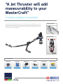
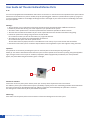
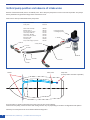
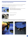
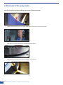
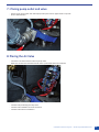
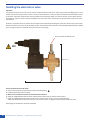
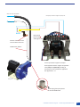
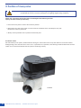
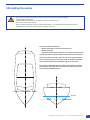
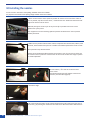
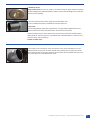
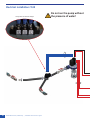
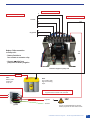
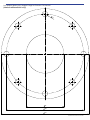
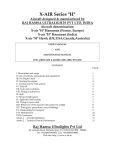
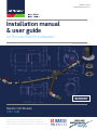
Manufactured by
Holland Marine Parts B.V.
Installation manual
& user guide
Jet Thruster Retrofit installation:
www.jetthruster.com
RETROFIT
MasterCraft Models:
X15 / X30
All our products are manufactured according to CE regulations.
We keep the rights to change descriptions, graphs or statements,
which are required for technical development of our Jet Thruster systems.
“A Jet Thruster will add
maneuvrability to your
MasterCraft”
Complete installation kit available!
Boat view single:
The operation of the Jet Thruster Single is based on the sucking in of outside water. It is subsequently expelled through nozzles in the bow and/or stern side. To this end the Jet Thruster has been
fitted with a powerful centrifugal pump, a three-way valve and electrical controls. These parts are
included for a Jet Thruster Single setup:
Manouevering:
Bow Truster
Main components:
2
Water inlet
Pump unit
3-Way valve
Nozzles
Joystick panel
Optima Battery
I-302-00
JTS-30-00/JTS-50-00
V-100-00
I-318-00
I-150-00
B-55-L
Holland Marine Parts / MasterCraft | Installation manual and user guide
“There isn’t a
single boat where
this thruster
can’t go in”
“We have been looking for many
years for a thruster system to install
in the bigger Mastercraft fleet,
finally with the new Jet Thruster we
can offer a incredible hassle and
noise free maneuverability to our
customers and it becomes also a
factory Option in all the bigger
Models!
RETROFIT
DIETER HOFER
MASTERCRAFT IMPORTER SWITZERLAND
MasterCraft: X-30
RETROFIT
MasterCraft: X-star
Installation manual and user guide
MasterCraft / Holland Marine Parts
3
Warranty provisions
On all its newly manufactured products Holland Marine Parts provides quality assurance regarding their proper
operation, both with regard to the material and the work done, including latent defects, for a period of 24 months after the
invoice date to the first receiver.
In case of defects in material and/or defects caused by inadequate work done, as covered under warranty by
Holland Marine Parts, the relevant part or the whole device will be either repaired or replaced at the discretion
Holland Marine Parts, free of charge.
The warranty periods specified in the first paragraph are not extended by the implementation of repairs under warranty.
Any costs associated with travel, transportation and installation and/or disassembly with regard to repairs
covered under warranty will be borne by the owner of that device.
Damage to the product caused by improper installation, by intentional or unintentional misuse, lack of maintenance, normal
wear and/or repair by third parties without the written permission of Holland Marine Parts are not covered by warranty.
Holland Marine Parts shall under no circumstances be liable for any consequential damages of any nature whatsoever or
howsoever caused by the part or the whole product covered by warranty by Holland Marine Parts.
4
Holland Marine Parts / MasterCraft | Installation manual and user guide
Safety:
read this prior to installation or operation.
This installation manual provides advice about the complete installation of the Jet Thruster.
Remarks about safety are accompanied by this symbol.
In rare conditions it might be possible that the pump unit of the Jet Thruster does not prime. If you notice a high rpm from the
pump unit and no thrust force, do not attempt to prime the pump unit by continuous activating the system. In this situation the
Electrical air valve from Holland Marine Parts should be installed to release the air from the pump head. This will prime the pump.
Do not run the pump unit without the presence of water!
Follow all instructions in this manual. All users of the system must be aware of the mandatory safety
regulations as explained in this manual:
- Preferably leave installation and maintenance of the system to a dealer authorised by Holland Marine Parts.
- Use appropriate tools for the installation and maintenance of the Jet Thruster.
- Provide the Jet Thruster seperate battery.
Place the battery as close to the pump unit of the Jet Thruster as possible.
- Always use a Holland Marine Parts control panel.
- Do not touch any moving parts of an active system.
- Parts such as the DC pump motor may become hot: do not touch them and do not cover them under any circumstances.
- Avoid having flammable products near the DC pump motor.
- Do not conduct any inspection or maintenance of the system when it is active.
- Do not close any valves of an active system.
- The system is located beneath the water line. Do not remove any parts of the system before all valves have been closed.
- Close all valves when you are not aboard.
- Leave system maintenance to specialists.
- Disconnect the battery cables when conducting maintenance and in the event of long-term absence
(e.g. when the vessel is not being used in winter).
- The hoses are under pressure in an active system: high-pressure hoses are to be attached to the vessel
to prevent movement along e.g. sharp edges.
- Protect the high-pressure hoses from heat / penetration / sunlight / chemicals.
- Avoid physical contact with the water inlet when the system is active.
- Avoid physical contact (swimmers!) with the nozzles and the water expelled by an active system.
- Danger! Protect pump unit and 3-way valve from petrol fumes.
Provide sufficient ventilation. Ignition proof covers are available.
Installation manual and user guide
MasterCraft / Holland Marine Parts
5
User Guide Jet Thruster Holland Marine Parts
JT-30
Your vessel is equipped with a Holland Marine Parts electric Jet Thruster. For the safe and correct operation of this system Holland
Marine Parts recommends every user to carefully study this operating guide. Familiarise yourself with the system by trying it out
in various weather conditions. The windage and draught as well as the weight of your vessel are factors contributing to how well
the system operates.
Warnings:
•The Jet Thruster is not a replacement of the main controls but assists with the execution of difficult manoeuvres.
•Familiarise yourself with the way your vessel responds to your operation of the system.
•The electric motor produces heat. The thermal protection limits continuous operation to about 4 minutes.
•The water inlet is located on the bottom of your vessel. Inquire about the exact location of the water inlet grating.
•Prevent the system from sucking in large amounts of sand and dirt.
Do not activate it when you have less than 30cm (12”) of ground clearance.
•The nozzles of the Jet Thruster are located beneath the water line.
Do not activate the system and do not operate the Jet Thruster when there are people, animals or vulnerable items in the vicinity of your vessel and the inlet and orifices.
•Close all the valves when you are not aboard. Inquire about the local regulations in ports with regard to closing the valves.
Operation:
You operate the Jet Thruster by activating the system on the front plate of the control panel by pressing the
button (A). This switch is illuminated in blue when the system is active. Operate the Jet Thruster by moving the joystick (B) left or
right, moving the bow or stern to port or starboard, respectively. When equipped with push buttons, the same procedure
applies, the push buttons being illuminated in green or red light.
B
A
Duration of activation:
Prevent the use of many short pulses. Instead, move your vessel by means of pulses that last a few seconds.
The efficiency of the system is determined in part by the battery capacity present. The overheating protection will activate when
the system is active for an extended period of time. After the engine has cooled sufficiently this protection is removed.
The cooling time is determined in part by the ambient temperature.
Winterising:
Drain water from the system, before it has the chance to freeze and damage the Jet Thruster system
6
Holland Marine Parts / MasterCraft | Installation manual and user guide
Troubleshooting
If the system is not functioning:
Problem
1.1 System is not working (power indicator off)
Cause
Solution
Joystick not receiving power
Press the switch
1.2 System is not working
Joystick not receiving power
(power indicator off)
Check fuse 15A
behind joystick
2.1 System is not working (power indicator on) Battery dead or main fuse broken
Check / replace fuse
2.2 System is not working
(power indicator on)
Damaged relay
Contact your dealer
Overheating protection activated
Leave engine to cool 3.1 Engine running, no activity
Valves closed
3.2 Engine running, no activity Engine does not draw water
Check whether or not
valves are closed
3.3 Engine running, no activity
Polluted system (shallow water)
Run engine in deep water
until clean
3.4 Engine running, no activity Contact your dealer
Damaged impeller
Place pump unit inlet
below water line
4.1 Engine running, no activity System operates inverted
Cabling fault
Exchange A and B on the pump unit
4.2 System is not efficient enough
Low battery voltage
Charge batteries,
Check actual voltage at meter.
Installation manual and user guide
MasterCraft / Holland Marine Parts
7
Vertical pump position and absence of intake valve
Because of the shallow draft, there is no butterfly valve. This to keep the pump house as close to the hull as possible. The pump is
directly installed on angled intake flange which is bolted to the hull.
A ball valve is directly installed behind the pump outlet.
Pumpunit JTVS-30-00
3-Way valve
JTVS-30-00
V-101-00
Water intake assembly
Butterfly valve 4”
Pressure hose 2”/51mm
Hose clamp 48-60 mm. Elbow 450 2” BSP M/F Hose connector 2”/51mm
Ball valve 2” BSP
Nozzles (steel)
Pump outlet straight 2”/51mm
I-600-00
I-603-00
I-113-00
I-114-00
I-316-00
I-115-00
I-317-00
I-318-00
I-142-00
I-336-00
Powerful special
centrifugal pump
P-156-00
3-way valve
I-317-00
I-603-00
I-316-00
I-600-00
I-114-00
I-113-00
V-201-00
I-115-00
Nozzle
3-way valve
Pump unit
(as deep under waterline as possible)
This instruction is a guide to install the Jet thruster system in Your X15 or X30 boat.
Locations for the pump, nozzles and valves and routing of hoses may vary depending on the boat’s configurations and options!
Please dry fit all components for fit and location before drilling holes!
8
Holland Marine Parts / MasterCraft | Installation manual and user guide
1: Preparation: Position of Angled Flange
- Find a place as deep under the waterline as possible
- Measure the angle which enables a vertical position of pump unit
- Order the appropriate flange.
Available flanges: 0, 15, 25, 35 degree
-
-
-
-
Rotate the flange to determine where to drill
This rotation/positioning will determine how the pump outlet will eventually will be in the boat!
Carefully mark where to drill the inlet and the 8 bold holes
Drill perfectly without tolerance. The counter part of the Angled flange that is mounted from the outside of the vessel
must mate perfectly with the Angled Flange!
If necessary: Use your technical creativity to retrofit the Jet Thruster in your boat.
Installation manual and user guide
MasterCraft / Holland Marine Parts
9
2: Drilling
-
-
-
-
10
Drill the Central inlet with a Ø 105 mm drill
Drill the 8x holes bolds for inlet studs. Use a Ø 13 mm drill
Dry fit the Water inlet Flange and verify it mates with the inside Angled Flange.
Thoroughly Sand (Scotch brite) and clean/degrease the inside and outside of the hull in order
to prepare a perfect surface for the Sikaflex 291i adhesive
Holland Marine Parts / MasterCraft | Installation manual and user guide
3: Preparation for Water Inlet Flange
-
-
For better hydrodynamics: It is possible to grind the edge of the inlet flange.
These modification are custom and depend on the installation and the position of the flange in the hull.
Now is the time to perform these custom modifications, after installation this is very difficult.
Thoroughly clean the stainless steel parts prior to the application of the Sikaflex 291i adhesive.
Installation manual and user guide
MasterCraft / Holland Marine Parts
11
4: Installation of Water Inlet Flange
Outside the boat:
- Use sufficient Sikaflex! Seal it like a Boss…By tightening the nuts on the inside of the vessel,
surplus Sikaflex will be pressed out.
- Remove the adhesive and support the Water inlet Flange.
Inside the boat:
12
-
-
-
-
Apply Sikaflex 291i on the hull before the Angled flange mates with the Water Inlet Flange
Thoroughly apply Sikaflex 291i to all bolds from the Water Inlet Flange
Thoroughly tighten all 8 nuts.
Make sure all nuts are locked in place by the Sikaflex 291i
Holland Marine Parts / MasterCraft | Installation manual and user guide
5: Preparation of the Pump Head
The pump head will mate with the Angled flange. Between the Angled flange and the pump head there is a o-ring to provide sealing.
Caution: 8 holes with conical shaped cavities are cut the pump head. Each hole has a thread cut into the plastic.
Tighten thoroughly, but not over-tighten to prevent damage to this thread.
- Apply Sikaflex 291i to each hole
- Make sure to provide Sikaflex to the thread of all 8 bolds that screw in the pump head
- Do not use any other sealant than Sikaflex 291i for this job.
Leaks will occur if this procedure is not performed perfectly!
- Place provide o-ring to Angled Flange
- Mate pump head to Angle Flange
- Apply washers and nut
Caution: When tightening the nuts: Apply the hexagon tool to give counter pressure. Prevent the bolds from rotating when nuts get
tightened. Rotating nuts will damage the treads in the plastic pump house and may cause leaks if Sikaflex 291i seal is broken.
Installation manual and user guide
MasterCraft / Holland Marine Parts
13
6: Placement of the pump motor
Look for the marks on pump head and pump motor! These must mate!
14
- Carefully slide the pump motor in the pump head, check for the marks to mate them correctly.
- Make sure the O-ring is attached to the impeller flange of the motor
- Apply provide pump house bolds and nuts and tighten with 9 Nm max.
Holland Marine Parts / MasterCraft | Installation manual and user guide
7 : Placing pump outlet and valve
- Directly to the pump outlet side: Attach pump outlet part with air nipple socket on top side.
- Place 2” BSP ball Valve
8: Placing the Air Valve
- Connect the Air Valve with the socket on pump outlet.
- Make sure the electrical solenoid of the Air Valve is placed well above the waterline.
- Continue with positioning of 3-Way Valve.
- Continue with installation of nozzles and hoses
- Continue with Electrical installation.
Installation manual and user guide
MasterCraft / Holland Marine Parts
15
Installing the electrical air valve
Operation:
The pump head of the Jet Thruster system must be installed under the water line in order to prime this centrifugal pump. In some
limited cases of fast moving vessels a vacuum can be produced when the nozzles rise above the waterline and the intake remains
in the water. The suction under the fast moving hull will retract the present water from the Jet Thruster system. When the boat
slows down or stops the water will automatically flow into the system due to the fact that the pump head and nozzles are under
the waterline.
However, it is possible that an air pocket can be trapped in the pump head preventing the pump from self priming. In this unique
situation an Electrical Air valve can be installed, this will release the present air from the pump head allowing the pump to rapidly
prime. Giving the operator immediate thrust pressure for maneuvering. Hose connector for Ø 8 mm hose.
12V
100 mm / 4 ”
90 mm / 3 ⅟₂ ”
How to install the Electrical Air Valve:
A. Remove the winterization plug located on the pump outlet fitting. A
B. Install the provided ⅛ hose connector.
C. Make sure to install the Electrical Air Valve above the waterline! D. Apply the supplied flexible hose and hose clamps between the pump unit and Electrical Air Valve.
E. Apply the supplied flexible hose from the Air valve to outside of the vessel. In case of a technical failure,
water that comes from the pump unit when the Jet Thruster system is engaged, will be pumped outside the vessel.
Follow diagram complete the electrical installation.
16
Holland Marine Parts / MasterCraft | Installation manual and user guide
Water to 3-way valve/nozzle
Example of a contactor support on pump unit
air leading out of vessel
X
- Blue ground
- Brown 12V F
- Yellow/green not in use
F
G
Position of electrical valve
must be above water line.
Flexible hose, Ø 8mm
Picture of contactor support is example.
Select applied contactor support and position
of F (+12V) and G (Ground) according to
the pump unit the installation is applied for.
See appendix A1 - F1
Pump unit
A
Remove plug from pump outlet
to connect flexible hose.
Installation manual and user guide
MasterCraft / Holland Marine Parts
17
9: Position of 3-way valve
CAUTION:
Prevent physical injury! When electrically turning the plunger present in the valve body,
considerable force occurs. Prevent any body parts from getting trapped during installation.
Please note: By opening the lit of the valve, the watertight seal and bearing is broken.
Opening the valve will void your warranty.
•Place of the 3-way valve as close to the nozzles as possible.
•Mount the 3-way valve to the vessel. Use the recesses at the bottom of the valve body for this. (m8)
Possition not necessary horizontal.
•Allways use the protective cover to protect the electrical parts.
Jet Thruster Combi:
Dirt that builds up in the system, will be flushed out during use. The function of the 3-way valve allows for an amount of water
flowing through, even when the valve is not in use. In a system that is in operation, water flowing out will be observed in all of the
nozzles. This is normal and indicates that the system is functioning correctly.
V-100-00
18
Holland Marine Parts / MasterCraft | Installation manual and user guide
10 Installing the nozzles
-
-
-
The Jet Thruster will be most effective when the nozzles are placed AS FAR AS POSSIBLE
TO THE FRONT OF THE BOW.
(shifted position possible as seen in diagram, to increase leverage arm).
Top side of nozzle below waterline.
Keep in mind that when the nozzles rise above the waterline , it is possible by the powerful Jet of water
expelled by the Jet Thruster inconvenience or damage may occur.
Principle for optimum installation:
•Nozzles at 900 angle to the centre line of the vessel
•Nozzles horizontal
•Top side of nozzle below the waterline. It is realistic to indicate that the
topside of the nozzle in optimum position will be just below the waterline.
This does not affect the function at all, but may causes spray. Be aware of
that. Preferably keep the nozzles ad deep under the waterline as possible,
but keep them horizontal and in 90 degree angle to the centre line.
If you not feel comfortable about the position of the waterline, we advise
you to take the boat in the water, and mark the line before you continue
the Jet Thruster installation process.
waterline
Installation manual and user guide
MasterCraft / Holland Marine Parts
19
10 Installing the nozzles
In case of steel or aluminum vessel plating weldable nozzles are available.
For polyester and wooden vessel plating flange treaded nozzles are available.
1: Place vessel horizontal. Select optimum position for nozzle: As far to the front of bow or
stern as possible, top side of nozzle 10cm / 4” below water line. Nozzle horizontal and in 90˚
angle to the heart line of the vessel.
Note: Not placing the nozzles as far to the front or aft as possible reduces the overall
effectiveness of the system!
Laser equipment can assist selecting optimum position and determine if vessel is placed
perfectly horizontal.
2: Make sure the position of both nozzles and the components like the ball valves, elbows, hose
connector, hoses and hose clamp are not in conflict with available space before a hole is made.
Drill a pilot hole. Keep drill horizontal!
Nozzles can be positioned shifted horizontal and vertical in case of a narrow bow. Hoses can
be crossed in order to place the nozzles further to the front of the bow. See image at point 8
for visible explanation.
3-4: Use a 60mm / 2⅜” hole saw to drill the holes
for the nozzle.
Keep drill horizontal and in 90˚ position to the vessel’s
heart line. (see illustration page 30)
5: Smoothen edges
6: Fit in the nozzle and check if nozzle is placed horizontal and in 90˚ angle to the heart line of
the vessel e.g. by inserting the nozzle from the inside out to determine if hole is drilled correct.
20
Holland Marine Parts / MasterCraft | Installation manual and user guide
7: Outside of vessel:
Flange treaded nozzle: In case of an rough or not entire flat surface: Apply sealant for maritime
purposes: Sikaflex-291i / 3M 5200 adhesive / sealant on the side of the flange of the nozzle that
contacts the vessel plating.
In case of a smooth and flat surface: Apply the provided rubber seal.
Do not use additional sealant in combination with the rubber seal.
Inside vessel:
Place the PVC guide ring, white nylon ring and the 2” nut, apply sealant. Tightly fasten the nut.
Make sure the nozzle remains horizontal and in 90˚ heart line of the vessel.
Connect the ball valve, 45˚ elbow and the hose connector. All connections are BSP treaded.
Apply Sealant for maritime purposes: e.g. Sikaflex-291i / 3M 5200 adhesive / sealant at every
tread to connect and seal the parts.
Do NOT use teflon tape!
8: Thoroughly clean and degrease every tread that has to be connected. Make sure to use
sufficient sealant on the tread. At least 6 threads and smoothen with e.g. finger over entire
thread. Apply sealant on both parts that have to be installed. Remove spilled sealant immediately. Use acetone to remove Sikaflex-291i stains.
Installation manual and user guide
MasterCraft / Holland Marine Parts
21
Electrical installation JT-30
Do not run the pump without
the presence of water!
3-way valve Jet Thruster Single
CDE
22
Holland Marine Parts / MasterCraft | Installation manual and user guide
Positive / Electrical Air valve to: F
F
G: Connect with battery minus
E
to valve
Negative / Electrical Air valve to: G
G (-)
GROUND
D
C
A
to joystick
B
Battery Cable connection
to Pump unit:
(+)
12V
- Battery Positive to
free contact at contactor relay
- Connect A cable from
pump unit to battery negative
Contactor support on pump unit
Fuse 425A
Note:
Battery cable
length max.
1m/3.3ft
Note:
Use a battery with
high cold cranking
amps.
Switch A and B wires at contactor support
if joystick control needs to be reversed.
B
A
+
Fuse 15A
joystick
+ Ignition
- Ground
12V
Note:
Do not use the dedicated Jet Thruster
battery to power the 12V control circuit.
Installation manual and user guide
MasterCraft / Holland Marine Parts
23
24
Holland Marine Parts / MasterCraft | Installation manual and user guide
Drill pattern Water inlet / Angled Flange Jet Thruster JT30 Vertical
(MasterCraft Retrofit kit only!)
12
,5
90
185
210
Project &
Description
Installation manual and user guide
Template drill pattern Water inlet MasterCraft Retro fit
MasterCraft
Holland ANGLES
Marine
Parts
DIMENSIONS IN/MILLIMETERS,
IN DEGREES
TOLERANCES±0.2mm, ±1º UNLESS OTHERWISE SPECIFIED
0.03
0.03
0.2
0.2
0.2
Ra 3.2
25
©
US Marine Products
25 Constitution Drive, Taunton, MA 02780
Phone: 508 802-6035 • Fax: 508 802-6006
www.usmarineproducts.com • [email protected]
All our products are manufactured according to CE regulations.
We keep the rights to change descriptions, graphs or statements,
which are required for technical development of our Jet Thruster systems.