1
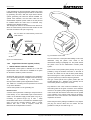
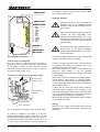
INSTALLATION MANUAL
WHISPER 8 / 10 / 12 / 16
ULTRA
- 1500 RPM -
Marine diesel generating set 230V / 50Hz
Digital Diesel Control
Art.nr. 50200231
MASTERVOLT
Snijdersbergweg 93,
1105 AN Amsterdam
The Netherlands
Tel.: +31-20-3422100
Fax.: +31-20-6971006
www.mastervolt.com
V5 December 2008
TABLE OF CONTENTS
Copyright © 2008 Mastervolt. All rights reserved.
Reproduction, transfer, distribution or storage of part or all of the contents in this document in any form without the prior written
permission of Mastervolt is prohibited.
TABLE OF CONTENTS:
1
INSTALLATION ............................................................................................................................................................... 3
1.1
General .............................................................................................................................................................. 3
1.2
Location.............................................................................................................................................................. 3
1.3
Instructions for optimal sound and vibration insulation ....................................................................................... 3
1.4
Ventilation........................................................................................................................................................... 4
1.5
Connections ....................................................................................................................................................... 4
1.5.1
Fuel supply ........................................................................................................................................ 8
1.5.2
Cooling .............................................................................................................................................. 9
1.5.3
Exhaust system ............................................................................................................................... 13
1.5.4
Digital Diesel Control system (12 Volt) ............................................................................................ 16
1.5.5
AC power system (230 Volt)............................................................................................................ 18
2
INSTALLATION SPECIFICATIONS .............................................................................................................................. 20
2.1
General ............................................................................................................................................................ 20
2.2
Commission table............................................................................................................................................. 20
2.3
Installation specifications.................................................................................................................................. 21
2.4
Specification of the accessories ....................................................................................................................... 21
2.5
Installation materials......................................................................................................................................... 22
3
DIAGRAMS & DRAWINGS ........................................................................................................................................... 30
3.1
DC wiring Whisper 8 Ultra, 10 Ultra and 12 Ultra ............................................................................................. 30
3.2
DC wiring Whisper 16 Ultra .............................................................................................................................. 32
3.3
Wiring diagram electronic governor (Whisper 10 and 12 Ultra only) ................................................................ 34
3.4
AC wiring diagram 230V / 50Hz ....................................................................................................................... 35
3.5
Remote control panel drawings ........................................................................................................................ 36
3.6
Dimensions Whisper 8 and 10 Ultra ................................................................................................................. 37
3.7
Dimensions Whisper 12 Ultra ........................................................................................................................... 38
3.8
Dimensions Whisper 16 Ultra ........................................................................................................................... 39
2
Copyright © 2008 Mastervolt / December 2008 / WHISPER 8/10/12/16 ULTRA / EN
INSTALLATION
1 INSTALLATION
1.1
GENERAL
1.3
INSTRUCTIONS FOR OPTIMAL SOUND
AND VIBRATION INSULATION
This installation manual is valid for the following models:
Part
number
51106005
51106006
51109005
51109006
51107005
51107006
51108005
51108006
Description
Whisper 8 Ultra 230V 1500rpm
Whisper 8 Ultra 230V 1500rpm -ungrounded
Whisper 10 Ultra 230V 1500rpm
Whisper 10 Ultra 230V 1500rpm -ungrounded
Whisper 12 Ultra 230V 1500rpm
Whisper 12 Ultra 230V 1500rpm -ungrounded
Whisper 16 Ultra 230V 1500rpm
Whisper 16 Ultra 230V 1500rpm -ungrounded
Position the generating set as low as possible in the
vessel. As the generating set is already secured to the
base frame by means of flexible engine mountings, the
frame must be mounted directly, without additional
vibration dampers, to the vessel’s main structure.
Whisper generating sets are standard equipped with a
sound cover. The canopy has been designed to give
effective sound insulation. For optimum sound and
vibration dampening, the following factors should be
considered.
For other models see our website: www.mastervolt.com
To ensure reliability and durability of the equipment, it is
very important that the installation is carried out with the
utmost care and attention. To avoid problems, such as
temperature problems, noise levels, vibration, etc. the
instructions set out in this manual must be followed and all
installation work must be carried out professionally.
1.2
LOCATION
Since Whisper generating sets have extremely compact
dimensions, they can be installed in tight locations. Please
consider that even almost maintenance-free machinery
must still remain accessible.
When selecting the location area in which to mount the
generating set, make sure there is sufficient room to carry
out any maintenance work. The unit must be easily
accessible on the service side and on the distribution side
to have access to the V-belt
Please also note that in spite of the automatic oil pressure
sensor it is still essential that the oil level is checked
regularly.
Figure 1: Mounting of the Whisper generating set.
1
Most important is the structure on which the generator
is places to be stiff. Directly below the rubber
mountings the structure should be supported vertically
to the superstructure of the ship.
2
Avoid mounting the generating set in close proximity
to thin walls or floors that may cause resonance.
3
Sound dampening is extremely poor if the generating
set is mounted on a light weight flimsy surface such
as plywood which will only amplify vibrations. If
mounting on a thinner surface cannot be avoided, this
should be at least be reinforced with stiffening struts
or ribbing. If possible, holes should be drilled or cut
through the surface to help reduce the resonance.
Covering the surrounding walls and floors with a
heavy coating plus foam will certainly improve the
situation.
4
Never connect the base of the generating set directly
to bulkheads or tanks.
X = wrong, V = OK
EN / WHISPER 8/10/12/16 ULTRA / December 2008 / Copyright © 2008 Mastervolt
3
INSTALLATION
1.4
VENTILATION
1.5
The generating set normally draws air from the engine
room. Engine rooms with natural ventilation must have
vent openings of adequate size and location to enable the
generating set to operate without overheating. To allow an
ample supply of air within the temperature limits of the
generating set an opening of at least 100 cm2 is required.
A "sealed" engine compartment must have a good
extraction ventilator to maintain reasonable engine room
temperatures. High temperature of intake air reduces
engine performance and increases engine coolant
temperatures. Air temperatures above 40°C reduce the
engine power by 2% for each 5°C of rise. To minimise
these effects the engine room temperature must not be
more than 15ºC above the outside ambient air
temperature.
Apply a combination of ventilators, blowers and air intake
ducting to meet the temperature limit. The air inlet ducts
should run to the bottom of the engine room to clear fumes
from the bilge and to circulate fresh air. Air outlets should
be at the top of the engine room to remove the hottest air.
An engine room blower should be used as an extraction
ventilator to remove air from the engine room.
In cases where it is impossible to meet the above
mentioned temperature limit by using machine room
ventilation, connections are to be made for an air inlet
directly to the enclosure. With these connections the
generating set can be directly connected to an air duct.
Air inlets should be louvered, where appropriate, to protect
the engine room and to protect the generating set from
water spray. As an extra precaution, the fitting of a cowl
ventilator with a cover box located as high as possible, is
recommended.
4
CONNECTIONS
The generating set comes supplied with all supply lines
and output cable (i.e. electric cables, cooling water
connections, exhaust, fuel lines etc.) already connected to
the engine and generator. The supply lines are fed through
the capsule’s front base. The connections are marked as
shown in figures 2 till 4
All electrical connections, cable types and sizes must
comply with the appropriate national regulations. Supplied
cables are rated for ambient temperatures up to 70°C. If
the cables are required to meet higher temperature
requirements, they must be run through conduits.
ATTENTION!
Before working (installation) on the system
read the section safety instructions
Copyright © 2008 Mastervolt / December 2008 / WHISPER 8/10/12/16 ULTRA / EN
INSTALLATION
01
03
04
10
11
Bypass cooling water in
Ø19mm (3/4")
Bypass cooling water out
Ø19mm (3/4")
Expansion tank Ø8mm
Exhaust hose Ø51mm
Remote control
AC power output
05
06
07
08
09
Battery NEG (–) 25mm2
Battery POS (+) 25mm2
Raw water inlet Ø19mm
Fuel in Ø8mm
Fuel out Ø8mm
02
Fig. 2a Connections Whisper 8 / 10 Ultra
Fig. 2b Connections Whisper 8 / 10 Ultra
EN / WHISPER 8/10/12/16 ULTRA / December 2008 / Copyright © 2008 Mastervolt
5
INSTALLATION
01
02
04
05
06
Expansion tank Ø8mm
Bypass cooling water out
Ø19mm (3/4")
Bypass cooling water in
Ø19mm (3/4")
Exhaust hose Ø51mm
Remote control
AC power output
07
08
09
10
11
Battery NEG (–) 25mm2
Battery POS (+) 25mm2
Raw water inlet Ø19mm
Fuel in Ø8mm
Fuel out Ø8mm
03
Fig. 3a Connections Whisper 12 Ultra
Fig. 3b Connections Whisper 12 Ultra
6
Copyright © 2008 Mastervolt / December 2008 / WHISPER 8/10/12/16 ULTRA / EN
INSTALLATION
01
02
03
04
05
Fuel in Ø8mm
Battery NEG (–) 35mm2
Battery POS (+) 35mm2
Fuel out Ø8mm
Raw water inlet Ø25.4mm
06
07
Expansion tank Ø8mm
Bypass cooling water out
Ø25.4mm
Bypass cooling water in
Ø25.4mm
Exhaust hose Ø51mm
Remote control
AC power output
Fig. 4a Connections Whisper 16 Ultra
08
09
10
11
Fig. 4b Connections Whisper 16 Ultra
EN / WHISPER 8/10/12/16 ULTRA / December 2008 / Copyright © 2008 Mastervolt
7
INSTALLATION
1.5.1
Fuel supply
The tank will need a filling connection, a return connection
and an air ventilation connection which will require
protection against water entry.
Some official regulations do not allow connection points at
the base of the fuel tank; in this instance connections are
to be made at the top of the tank with internal tubing down
to a few cm above the bottom of the tank.
1 FUEL TANK
Fuel tanks should be made of appropriate material such as
(stainless) steel or plastic. Steel tanks should not be
galvanised or painted inside. Condensation can occur in
metal tanks when temperature changes. Therefore, water
accumulates at the bottom of the tank and provisions
should be made for the drainage of this water.
Fig. 5 Fuel supply (fuel tank is above the generating set)
1 Fuel return
2 Fuel supply
3 Prefilter / Water separator (optional)
5 Fuel Tank
1
2
5
A
3
4
Fig. 6 Fuel supply (fuel tank is below the generating set)
1 Fuel return
2 Fuel supply
3 Prefilter / Water separator (optional)
8
4 Extra fuel lift pump (optional)
5 Fuel tank
Copyright © 2008 Mastervolt / December 2008 / WHISPER 8/10/12/16 ULTRA / EN
INSTALLATION
2 FUEL LIFT PUMP
The generating set itself is equipped with a fuel lift pump;
therefore the tank can be installed at a lower level than the
generating set. The maximum suction height is 1 m.
If the pump has to lift the fuel higher than one meter an
external fuel lift pump must be installed. The control board
is already prepared to connect an extra fuel pump.
3 FUEL PIPES
When the tank is above the generating set we recommend
ending the return line on the top of the tank.
When the return is on the top - in case of a leakage the
return line cannot overflow because of siphoning. One will
only need a fuel cock in the fuel supply line. When the tank
is below the generating set we recommend ending the
return line on the bottom of the tank (A) below the inlet of
the supply line.
Both supply and return fuel pipe lines should be
appropriate material and 8 mm outer diameter tubing. The
quality of the tubing of fuel pipes could be submitted to
local regulations depending on the application of the
vessel.
The fuel pipes can be plumbed to the flexible hoses which
are on the generating set and have a connection to fit to 8
mm pipe. This fuel lines fulfils CE standards and are
according to ISO 7840 A2.
It is important to avoid bends in the pipes, as they could
trap air bubbles. The return pipe should never be
connected to the suction pipe. Other consumers of diesel
fuel, such as the propulsion engine and heaters, have to
be connected to separate suction and return pipes
4 FUEL FILTERS
A fine fuel filter is installed which requires maintenance.
Mastervolt advises to install an extra fuel filter/ water fuel
separator near the fuel tank.
Before starting your generating set for the first time follow
the fuel system bleeding procedure in the users manual.
1.5.2
Cooling
Intercooling is based on a raw water pump, heat
exchanger and water-injected exhaust. Cooling liquid in
the internal cooling system is cooled in a heatexchanger
by outboard water (raw water or seawater). After the raw
water is warmed up in the heatexchanger it is dumped
overboard by injecting it in the exhaust.
The generating set should have its own sea water (coolant
water) inlet and should not be connected to any other
engine systems. A properly installed cooling system is
critical to keep engine temperatures within an acceptable
range. Ensure that the installation complies to the
following installation instructions.
1 THE INTERNAL COOLING SYSTEM
The internal cooling system should be filled with cooling
liquid. (Refer to the users manual 2.5.12) When the engine
becomes hot the liquid expands and the system is
pressurised. After the pressure becomes too high the
release valve in the filling cap on the manifold opens and
the expanding liquid is pressed into the expansion tank
that is in the delivery. Also the air in the system that is
collected at the top of the manifold is released in this way.
When the liquid cools down there will be under-pressure.
Another valve opens and the liquid is sucked into the
manifold again. This system works only when there is
enough liquid initially. This has to be checked when
commissioning the generator set. By filling up the
expansion tank when necessary there will always be
enough liquid in the system. The hose that is in the
delivery has to be connected to the connection on the side
of the filling cap. This hose is made of heat resistant
plastic and is not sensitive for kinks.
MAX.
Fig.7: Expansion tank placement
The tank has to be placed close to the generator. When it
is mounted above the top of the manifold the liquid in the
tank will be drained when the cap on the manifold is taken
off. When keel cooling or radiator cooling is applied the
system will not be pressurised. A cap without release
EN / WHISPER 8/10/12/16 ULTRA / December 2008 / Copyright © 2008 Mastervolt
9
INSTALLATION
valve should be applied. Refer to the special manual for
these applications.
2 RAW WATER SUPPLY
For raw water supply the following installation materials
are required: -a skin fitting - a sea cock - a water strainer hoses and clamps. In order to keep the suction resistance
in the line at a minimum, the sea water intake system (i.e.
sea cock, tru-hull fitting, inlet filter, etc.) must have the
following inner diameter at least:
Model
Whisper 8, 10, 12 Ultra
Whisper 16 Ultra
Minimum inner diameter
19 mm (3/4")
25.4 mm (1")
The suction hose should be kept as short as possible.
Raw water plumbing should avoid bends as much as
possible.
Restriction of raw water flow, caused by kinked hoses,
undersized pipes or connections, will reduce the engine
cooling capability. This is the main cause for overheating
of an engine.
After running the generating set for the first time, check the
coolant flow rate using a stopwatch and by holding a pail
of a known volume under the wet-exhaust outlet. The flow
rate should be according to the data in the users manual
5
2
Max.
60"
150cm
Min.
24"
60cm
1
Min.
24"
60cm
6
2"
5cm
4
3
7
Fig. 8. Internal cooling system
1 Water level;
2 Water/exhaust separator;
3 Seacock;
4 Waterlock;
5 Air vent;
6 Water strainer;
7 Seacock.
10
Copyright © 2008 Mastervolt / December 2008 / WHISPER 8/10/12/16 ULTRA / EN
INSTALLATION
3 INSTALLATION OF THROUGH HULL FITTING
It is good practice for yachts to use a hull inlet fitting with
an integrated strainer (water scoop). For propulsion
engines in motorboats the water scoop is often mounted
against the sailing direction to induce more water intake
for cooling.
This should not be done in the case of a
generating set! When sailing at higher
speeds, water will be forced into the inlet and
your generating set will overflow!
5 SIPHON BREAKER (AIR VENT)
When the point of water injection is below the waterline,
then -when the engine is stopped -there is a risk that the
cooling water may enter the engine as a result of
siphoning. To avoid this happening, the generating set is
designed to accommodate a siphon breaker (air vent). In
the standard delivery the connections are bypassed. See
figure 10
SAILING DIRECTION
FLOW DIRECTION
SAILING DIRECTION
FLOW DIRECTION
Fig. 10: Bypassed siphon breaker connections
Fig. 9 Installing water intake
On motorboats and on sailing boats the water scoop for a
generating set should be fitted with the opening faced
backwards to prevent water being forced in during sailing.
4 WATER STRAINER
Use an appropriate water strainer with connections of the
following dimensions:
Model
Whisper 8, 10, 12 Ultra
Whisper 16 Ultra
Inner dimensions
19 mm (3/4")
25.4 mm (1")
Install the water strainer in a well accessible position,
(refer to fig. 8, ref. 6) 5 cm above the waterline.
Hoses with the following inner diameter should be used:
Model
Inner dimensions
Whisper 8, 10, 12 Ultra
19 mm (3/4")
Whisper 16 Ultra
25.4 mm (1")
If the generating set cannot be mounted such that the
bottom of the generating set is placed above the waterline,
an air vent must be installed. See figure 11
Extend the water hose of the by-pass 60 cm above
waterline and install an air vent. Ideally, the air vent should
be mounted above the yacht keel center line (i.e. to
minimize the influence of swaying on the water intake).
Fast motorboats will lay deeper when sailing at large
speed and can cause pressure on the waterinlet. This
should be avoided to prevent fleeding the engine.
If the air vent is clogged the water hoses will
not be vented when the generating set has
stopped and water can be forced into the
engine. This leads to immediate engine
problems and eventually severe damage!
DAMAGE CAUSED BY THE INGRESS OF WATER IN
THE ENGINE IS NOT COVERED BY GUARANTEE
EN / WHISPER 8/10/12/16 ULTRA / December 2008 / Copyright © 2008 Mastervolt
11
INSTALLATION
OPEN
Siphon breaker
Fig. 13 Mastervolt siphon breaker
Fig.11 siphon breaker connected
On the valve is a little hose to drain a little water that could
be spilled from the valve. This hose should go down and
may not end under water, because it should ventilate air
into the valve to break the siphoning.
OPEN
Fig 12: Wrong siphon breaker hose routing
Check the air vent at regular intervals. Open, clean and
lubricate the valve as required.
12
Copyright © 2008 Mastervolt / December 2008 / WHISPER 8/10/12/16 ULTRA / EN
INSTALLATION
1.5.3
Exhaust system
diameter of 51 mm no less, no more-. The exhaust system
must be installed so that the back pressure inside the
exhaust does not exceed 0.07 bar (1psi – 70 cm
watercolumn) and total length from the genearot to the top
of the goose neck or or water/separator does not exceed
3m (10 ft.). (Refer to paragraph 5.4.3 of the users manual).
Water is injected in the exhaust system of the generating
set. In this way the cooling water that has passed the heat
exchanger is mixed with the exhaust gases. Temperature
and volume of the gases are thereby reduced
considerably, so that a rubber exhaust hose can be used
and the level of noise is reduced as well.
The exhaust hose descends from the capsule to the water
lock. Then the hose rises via the "goose neck" to the
through-hull exhaust outlet, situated minimum 50 mm
above the water line (ref. to fig. 14, ref. 5.) The "goose
neck" must be vertical and situated preferable along the
ship’s keel center line. If the generating set is mounted
less than 60 cm (24") above the waterline, a "goose neck"
must be installed to prevent the engine from overflowing. It
is recommended to install an extra muffler close to the
through-hull fitting. .
1 STANDARD EXHAUST SYSTEM INSTALLATION
The generating set exhaust system must remain
completely independent and separate from the exhaust
system of any other engine on board. A water lock
prevents the generating set from being flooded by cooling
water and should be installed as close to the generating
set as possible. The lock must be large enough to hold the
entire water volume held in the hose from the top of the
goose neck to the water lock. The water lock must be
installed at the lowest point of the exhaust system (ref. to
fig. 14, ref. 1). The exhaust hose must have an inner
HOSE ROUTE A- B MAX. 10ft (3m)
A
B
Minimal 24" 60cm
60" 150cm
4
3
2" 5cm
5
Maximal
2
3
1
6
Fig. 14: Standard exhaust system
1 Exhaust water lock;
2 Exhaust outlet muffler;
3 Exhaust line Ø 51 mm (2”);
4 Goose neck
5 Through-hull exhaust outlet Ø 51 mm (2”);
6 Water level.
EN / WHISPER 8/10/12/16 ULTRA / December 2008 / Copyright © 2008 Mastervolt
13
INSTALLATION
2
MIN. 3CM (1,2")
Ø 2”
51 mm
MAX. 10CM (4")
Ø 1 5/8”
40 mm
MAX. 150CM (60")
MIN. 60CM (24")
A
Ø 2”
51 mm
B
1
3
4
1 Water level
2 Water/exhaust separator
3 Seacock
4 Waterlock
Figure 15: Super silent exhaust system
WRONG!
Max. length A - B = 3 m (10 ft.)
Maximum length: 10 m (30ft)
A
Ø 2” (51 mm)
Ø 15/8” (40 mm)
Ø 2” (51 mm)
OK!
B
Ø 2” (51 mm)
Figure 16: Only after the exhaust / water separator the exhaust hose may have a length of over 7.5 meter
14
Copyright © 2008 Mastervolt / December 2008 / WHISPER 8/10/12/16 ULTRA / EN
INSTALLATION
2
"SUPER SILENT" EXHAUST SYSTEM
See figure 15. In order to reduce the noise level of the
generating set to a minimum, an option to reduce the
exhaust noise further (especially exhaust water splashing)
is an exhaust/water separator. The exhaust/water
separator allows the cooling water to be ejected through a
line separate from the exhaust fumes and also functions
as a goose neck to prevent water from flooding the engine.
If the exhaust/water separator is mounted more than 60
cm above the water level an additional goose neck is not
required.
OK!
If the through-hull exhaust outlet has to be mounted far
from the generating set (total length of the exhaust piping
from generator to top of goose neck (water separator) is
more than 3 m.), an exhaust/water separator must
definitely be installed (see figure 16). The sea water from
the separator must then run down along the shortest
possible path to the through-hull outlet.
However watertraps should be avoided as the fumes still
contains water and this should not accumulate in bents
(refer to fig 17 and 18). An additional outlet exhaust
muffler close to the hull outlet (fig. 14, ref 2) will help
further to reduce noise emission
WRONG
Figure 17: Water trap in exhaust system
OK!
WRONG!
Figure 18: Water will collect in the hanging bend of the exhaust gas hose and will cause back pressure
EN / WHISPER 8/10/12/16 ULTRA / December 2008 / Copyright © 2008 Mastervolt
15
INSTALLATION
If the generating set and the exhaust system have been
installed correctly, neighbouring boats will not be disturbed
by generating set noise, With the "super silent" exhaust
system, generating set noises are almost inaudible. For
optimal noise reduction, the sea water outlet from the
exhaust/water separator (center outlet on the unit) should
be installed below the water level to eliminate noisy
splashing of the effluent sea water.
The through-hull outlet for the exhaust fumes should not
direct the fumes directly toward the water surface as this
will cause excessive noise (ref. to figure 19).
Do not direct the outlet directly toward the
water surface.
WRONG!
OK!
Fig. 20 Remote control cable
Figure 19: Outlet direction
1.5.4
Digital Diesel Control system (12 Volt)
1 DIGITAL DIESEL CONTROL SYSTEM
The electrical control system is standard in 12 Volt with
negative earth. Non- earth return is available as an option
for aluminium vessels to prevent corrosion.
All electrical wiring has been prepared on the generating
set to the control panel prior to despatch from the factory.
The engine is controlled by a very advanced
microprocessor based system: Digital Diesel Control.
The “black box” containing the microprocessor is located
on top of the alternator.
A local control panel is on the generating set.
Remote control
A remote control panel also containing a microprocessor is
in the delivery. A 15 m intermediate 8-pole communication
cable is in the standard supply as well (refer to fig. 20). If
necessary an optional longer (up to 30m / 100ft)
intermediate cable can be connected if the standard length
does not suit the required distance. When a longer
distance than 30m / 100ft is required, consult the
Mastervolt service department for advice.
16
One can mount the control panel after drilling a hole in the
dashboard using the plastic cover. Refer to the
dimensional drawing in paragraph 3.5. The panel without
the plastic cover fits the Mastervision modular panel
system.
More remote control panels (slave panels) can be put in
parallel by using the modular connectors on the back of
the units. As a slave one can use the same panel offering
all functions again. It is also possible to use an old or new
type slave panel only to start and stop the generator.
Old type remote panels and system panels (like the
System Manager AC + Whisper or the CSCP4) can be
connected by means of the green connector.
Pay attention to the colour codes as indicated in fig. 21
when fitting cable to the green connector. Some software
versions in old system panels (supplied before May 2004)
could conflict with the software in the DDC and an update
of the software of the system panel could be necessary.
When this is the case consult to the Mastervolt service
department for advice.
When using the factory settings, installation is very simple:
just plug the remote cable into the remote and the
generator is ready to use. Refer to fig. 21.
Copyright © 2008 Mastervolt / December 2008 / WHISPER 8/10/12/16 ULTRA / EN
INSTALLATION
REMOTE CABLE
an emergency switch or a potential free fire alarm switch
with normally closed contacts
Automatic start/stop
REMOTE CABLE
Mastervolt cannot be held responsible for
damage caused by the unattended running
generator using the auto-start/stop mode or
interval mode
12
11
10
9
8
7
J3
6
5
4
3
2
1
WIRING COLOURS
1
2
3
4
5
6
7
8
9
RED
GREEN
BROWN
YELLOW
PINK
PURPLE
BLUE
WHITE
RED/BLUE
10
11
12
GREY/PINK
GREY
BLACK
Using the auto-start/stop (interval) mode the
generator can start unexpectedly. When
working on the electrical system, the 3 Amp
fuse must be removed from the control panel
and the battery plus cable must be removed
from the battery.
SENSE BAT. 2
WRP/2
In the delivery are warning stickers to stick on
several parts of the electric installation
(transfer switch, distribution box, etc.) to warn
for automatic start)
WARNING RELAY
MAX. 150 mA
Whisper Remote Panel
Fig. 21 Remote box terminals
The Mastervolt Digital Diesel Control system offers several
options for automatic starting and stopping.
Acoustic alarm or warning lamp
One can connect an external max.150 mA relay to
generate an acoustic warning or applying a warning lamp
etc. Be aware of polarity as some relays has a diode
inside and should be connected plus to plus en minus to
minus as indicated. Refer to fig. 21.
Connection for emergency stop / fire alarm switch
Remove bypass
between J7 - J18
local control panel
(rear view)
Access to this menu and other menus could be blocked.
For blocking and setting up this options refer to the
APPENDIX of the DDC users manual.
One of these options is to monitor a second battery (not
being the starter battery) to start the generator
automatically when the voltage of this battery drops below
a certain setting.
Other names for this second battery are “auxiliary battery”,
“service battery”, ”users battery” or “consumers battery”.
We will refer to this battery as “the second battery”(BAT2).
In some menus the starter battery could be indicated as
“the first battery” (BAT1).
A sense wire to monitor the second battery should be
connected (attention polarity!) to the connector on the
back of the remote panel. Refer to fig. 21. The sense wires
must be connected directly on the second battery before a
main switch and be protected by a 3 Amps fuse.
(Monitoring the generator starter battery does not require
an extra sense connection)
Normal operation
Alarm / emergency
Fig. 22: Connection for emergency stop / fire alarm switch
Settings
When one want to apply other settings than the factory
settings refer to the DDC users manual, especially to the
APPENDIX.
To connect an emergency stop button or to stop the
generator automatically in case of a fire alarm, you can
use the bypass connection between fastons J7 and J18 on
the backside of the local control panel. See fig. 22. To do
so, remove this bypass connection and then replace it by
EN / WHISPER 8/10/12/16 ULTRA / December 2008 / Copyright © 2008 Mastervolt
17
INSTALLATION
2 STARTER BATTERY
For starting, the Whisper requires a 12V starter battery
with the following capacity:
Model
Whisper 8, 10, 12 Ultra
Whisper 16 Ultra
Minimum capacity
70Ah
120Ah
The generating set can be connected with the main engine
battery or have its own battery.
We strongly recommend the use of a separate battery for
the generating set and to keep the wiring system for the
propulsion engine and the domestic DC supply system
completely separate and individually connected to
separate batteries.
230VAC
IVO 12/10
A
3 OTHER RECOMMENDATIONS AND WARNINGS
The battery should be secured for seagoing conditions and
the terminals should be insulated. For extra safety the
battery can be enclosed in a wooden, plastic, fiberglas etc.
(non metal) box. Even when the earth return system is
applied a negative battery cable should be used and the
vessel should not to be used as a conductor.
The battery cables are supplied in a standard length of 1.5
m, if longer cables are required a larger cross sectional
area should be considered to compensate for voltage
reduction.
When two batteries are used in series to provide a 24 Volt
supply system, never take off 12 Volt (starting) power from
one of these batteries. This will result in severe damage to
both batteries within a short time.
Disconnect the battery leads if electrical welding is to be
carried out, otherwise damage will be caused to the diodes
of the alternator.
As explosive hydrogen gases may be
discharged during charging, the battery
should be located in a well ventilated room.
Ensure that the supplied battery cable
connectors are properly fitted and never
remove during or shortly after charging as
sparking can occur, which may ignite the
hydrogen gasses.
B
+
12V
-
Fig. 23 Starter battery
However, the negative of all the batteries on the vessel
should be interconnected (when on earth) to avoid
difference in the voltage level of the earth on different
places causing trouble to electronic devices which might
be in the system.
The above recommendation is not valid for ships having
the starter battery of the propulsion engine or other
auxiliary equipment positive grounded. When this is the
case an expert should be consulted.
A battery switch may be used to interrupt the positive
connection.
The starter battery is charged by the alternator on the
engine. An additional battery charger will help to keep the
battery in good condition when the generating set is not
used. A battery charger is not included in the standard
supply. A high efficiency battery charging unit can be
ordered from Mastervolt which is able to charge both the
ship’s main battery and the starter battery. Also a small
charger can be used to charge the starter battery only,
such as the IVO SMART 12/10. A battery switch and a
charger are included in the battery installation kits, art. no.
50230210 (70Ah) or 50230220 (160Ah)
18
1.5.5
AC power system (230 Volt)
Before working (installation) on the system
read the sections on safety in the users
manual.
Be sure that all electrical installations (including all safety
systems) comply with all required regulations of the local
authorities. All electrical safety/shutdown and circuit
breaking systems have to be installed onboard as the
generating set itself cannot be equipped with such
equipment for every possible variation.
The vessel’s power supply system should be suitable and
safe for the AC voltage which is applied and the power
that will be generated. Special attention has to be paid on
dividing the system in branches which are fused
individually.
It is absolutely essential that each and every circuit in the
on-board electrical system is properly installed by a
qualified electrician.
Copyright © 2008 Mastervolt / December 2008 / WHISPER 8/10/12/16 ULTRA / EN
INSTALLATION
1 FUSE
An output fuse (from the generating set to the system)
should be installed to protect the installed electrical
system. The following maximum single phase output
current applies:
Model
Whisper 8 Ultra
Whisper 10 Ultra
Whisper 12 Ultra
Whisper 16 Ultra
Maximum single phase
output current
35A
43A
52A
70A
The fuses must be of the slow reacting type. For electrical
motors connected to the system, a motor protection switch
must be installed
2 GROUNDING
The AC alternator windings are not grounded.
The housing of the alternator and all other metal parts are
grounded
To make a connection between “neutral” and “ground” is
necessary as part of a specific insulation failure protection
system.
Small pleasure craft in Europe (length up to 24 meter) is
submitted to The Recreational Craft Directive 94/25/EC.
The guidelines of this directive refer to (ISO 13297).
When the installation comply to this standard the “neutral”
and “ground” should be connected on the generating set
by connecting the blue (neutral) wire with the terminal on
which the yellow/green wire is connected.
A Ground Fault Circuit Interrupter (GFCI) or similar device
must be applied
WARNING
In all situations the transfer switches between
shore, inverter and generator should switch all
connections, the phase line (L) as wel as
neutral (N).
Be aware that insulation protection systems can be
different for different applications and even within the ship
there could be different standards for different spaces. We
did refer to the Recreational Craft Directive that applies to
pleasure craft up to 24 m of length. Sometimes one has to
comply with other standards such as the rules of
certification societies like Lloyds Register of Shipping or
Veritas, regulations for the protection of personal, building
legislation, etc. It is of the greatest importance to have
expert advice on this issue.
For safety reasons connect the main ships ground to
negative point of the generating set start battery. When a
ungrounded DC system or positive grounded DC system is
applied the battery negative should not be connected to
the main ships ground.
3 CABLE
For the power cable we recommend the use of 3 wire
single phase or 5 wire tri-phase oil resistant cable with a
sufficient cross sectional area. One wire for earth is
included. For long cables it is recommended to apply
cables with a larger cross section (refer to ISO 13297
annex A)
4 TRANSFER SWITCH
A power source selector switch much be installed between
the generating set and the ship’s electrical supply system.
This switch must ensure that all AC consumers can be
switched off at once. This switch should also be installed
to keep the generating set and shore (grid) power systems
separate.
Transfer switches - to switch over from shore to ship or
from generating set to inverter - should be well designed to
switch over all wires including neutral (and not only phases
or line) and there should be provisions with the aid of
timers to prevent relays from clattering.
Mastervolt recommends the installation of a Mass
Systemswitch as the power source selector. This works
automatically when the generating set is not running the
input remains in the shore position and as soon as the
generating set is running the Mass Systemswitch switches
automatically after 10 seconds delay time over to the
generating set position.
EN / WHISPER 8/10/12/16 ULTRA / December 2008 / Copyright © 2008 Mastervolt
19
INSTALLATION SPECIFICATIONS
2 INSTALLATION SPECIFICATIONS
2.1
GENERAL
7
1
Mount the generating set directly, without additional
vibration dampers, on a solid surface.
2 Connect the (sea) water inlet to the strainer.
3 Connect exhaust system.
4 Connect a siphon breaker or ‘air vent’ into the cooling
circuit, if necessary.
5 Connect ‘fuel supply line’ to the water separator/ fuel
filter.
6 Connect ‘fuel return line’ to the fuel tank.
7 Connect remote panel (just plug in).
8 Connect the AC cable from the AC box to the power
source selector (or Mass Systemswitch).
9 Connect plus and minus from the 12V starter battery
to the battery cables.
10 Install a Mastervolt battery charger. (optional)
2.2
1
2
3
4
5
6
20
8
9
10
11
COMMISSION TABLE
Check if a siphon breaker (air vent) is necessary and
has been installed
Open the seawater inlet valve and check all water
connections. Check if the strainer is installed on or
just above the seawater level.
Check if the exhaust system is properly installed.
Check maximum length of exhaust hose, diameter of
exhaust hose, position of the water lock, maximum lift.
Also check the minimum required height of 60 cm
above sea level of the exhaust loop (goose neck).
Open the seawater outlet valve and check all water
connections.
Check the AC cables and the grounding.
Check if an AC breaker is installed before or after the
power source selector. When there is only a circuit
breaker, use it to disconnect the generating set from
the grid.
12
13
14
15
16
17
18
Check all DC connections, check if the battery switch/
circuit breaker is closed.
Open the fuel valve. Check if there are no air leaks in
the fuel supply line, and check if the lift of the fuel is
less than 1 meter. Check if there is no air in the water
fuel separator.
Check if the air intake in the canopy is not blocked.
Check the oil level and colour of the oil. Check the
coolant level
To bleed the fuel system:
•
Whisper 8, 10, and 12 Ultra: push the “Start”
button on the local control (not on the remote
panel) and hold at least 5 seconds and as long as
necessary to bleed the system.
•
Whisper 16 Ultra: use the manual pump by
turning the cap loose and pumping as long as
necessary to bleed the system. See chapter 4.2.2
of the user’s manual.
Start the engine by pushing the start button
Check when the generating set is running, the delay
of 5 to 10 seconds in the power source selector
transfer.
Check voltage and frequency under ‘no load’
conditions.
Check voltage and frequency under ‘full load’
conditions.
Check if the battery charger of the generating set is
working (max. 14.5 Volt).
Close the sound shield and check the noise level.
Stop the generating set and check the engine again
for leakages of oil, fuel or water.
Installation checklist
www.mastervolt.com.
Commissioning form
www.mastervolt.com..
available
on
our
website:
available
on
our
website:
Copyright © 2008 Mastervolt / December 2008 / WHISPER 8/10/12/16 ULTRA / EN
INSTALLATION SPECIFICATIONS
2.3
INSTALLATION SPECIFICATIONS
TECHNICAL DATA
Model
Dimensions lxwxh.
Weight including sound shield
Max. operation angle
Remote panel 15 m cable
Battery capacity min.
Fuel consumption
Model fuel pump
Max lift fuel pump
Cooling
Cooling pump
Model cooling pump
Minimum water supply
Alternator
Voltage regulation
Output power at 50Hz
power factor cos phi = 1
Battery charger
2.4
Whisper 8 Ultra
Whisper 10 Ultra
Whisper 12 Ultra
90 x 58 x 63 cm
90 x 58 x 63 cm
106 x 58 x 63 cm
335 kg
335 kg
380 kg
25°
25°
25°
Digital Diesel Control System
12V / 70Ah
12V / 70Ah
12V / 70Ah
1,5 – 4 l/hr, load dependent
Electrical driven
Electrical driven
Electrical driven
12V
12V
12V
1m
1m
1m
Indirect
Indirect
Indirect
Mastervolt self priming raw water impeller pump, PTO driven
M12
M12
M12
18-22 l/min
18-22 l/min
18-22 l/min
synchronous brushless, maintenance free water cooled
capacitor (+ optional: AVR )
Whisper 16 Ultra
116 x 58 x 70 cm
440kg
25°
8 kW
16 kW
10 kW
12 kW
12V / 120Ah
Mechanical driven
Manual priming
1m
Indirect
M16
20-25 l/min
alternator including regulator (50 Amps)
SPECIFICATION OF THE ACCESSORIES
Model:
Water scoop
Inlet valve
Water strainer
Air vent
Inlet suction hose
Fuel filter/water separator
Fuel inlet and return
Exhaust hose
Water lock
Water/gas separator
Anti shock mounts
Battery charger (optional)
Whisper 8 Ultra
Whisper 16 Ultra
Whisper 10 Ultra
Whisper 12 Ultra
3/4” = 19 mm
1” = 25.4 mm
3/4” in / 19 mm out
1” in / 25.4 mm out
19 mm in / 19 mm out
25.4 mm in / 25.4 mm out
19 mm
25.4 mm
19 mm
25.4 mm
30 micron
30 micron
8 mm
8 mm
Ø 51 mm inner
Ø 51 mm inner
Ø 51 mm
Ø 51 mm
Ø 51 – 40 – 51 mm
Ø 51 – 40 – 51 mm
Included
Included
IVO SMART 12/10; 12V / 10 Amps, 230V/50Hz
EN / WHISPER 8/10/12/16 ULTRA / December 2008 / Copyright © 2008 Mastervolt
21
INSTALLATION SPECIFICATIONS
2.5
INSTALLATION MATERIALS
WATER INLET KIT 3/4” (20 mm) for Whisper 8 Ultra, 10 Ultra and 12 Ultra
no
qty
article no
description
1
1
50230052
Intake strainer
2
1
50230042
Lever operated ball valve FF
3
1
50221004
Male hose connection
4
4
50221502
Hose clamps
5
3
50220056
Outboard cooling water hose
6
2
50221007
Male hose connection
7
1
50230060
Nickel plated brass intake strainer
8
1
50230067
Mounting bracket waterstrainer
TOTAL
50230211
WATER INLET KIT 20 mm
dimensions
3/4
3/4
3/4x20
19-29 mm
20x28 mm
1/2x20
1/2
WATER INLET KIT 1” (25 mm) for Whisper 16 Ultra
no
qty
article no
description
1
1
50230053
Intake strainer
2
1
50230043
Lever operated ball valve FF
3
1
50221010
Male hose connection
4
4
50221503
Hose clamps
5
3
50220050
Outboard cooling water hose
6
2
50221008
Male hose connection
7
1
50230061
Nickel plated brass intake strainer
TOTAL
50230221
WATER INLET KIT 25 mm
dimensions
1”
1”
1”x25
26-38 mm
25x33 mm
3/4x25
3/4
AIR VENT KIT 3/4” (20 mm) for Whisper 8 Ultra, 10 Ultra and 12 Ultra
no
qty
article no
description
4
7
50221502
Hose clamps
5
3
50220056
Outboard cooling water hose
11
2
50221031
Bend male type with hose connection
12
1
50221042
TEE fittings
13
1
50230001
Syphon breaker valve
14
1
50221001
Male hose connection
15
1
50221521
Hose clamps
16
1,5
50220055
Outboard cooling water hose
TOTAL
50230212
AIR VENT KIT 20 mm
dimensions
19-29 mm
20x28 mm
1/2x20
1/2
1/2
3/8x13
12-20 mm
12x18.2 mm
AIR VENT KIT 1” (25 mm) for Whisper 16 Ultra
no
qty
article no
description
4
7
50221503
Hose clamps
5
3
50220050
Outboard cooling water hose
11
2
50221083
Bend male type with hose connection
12
1
50221043
TEE fittings
12
1
50221102
Straight reducer
13
1
50230001
Syphon breaker valve
11
2
50221008
Male hose connection
14
1
50221001
Male hose connection
15
1
50221521
Hose clamps
16
1,5
50220055
Outboard cooling water hose
TOTAL
50230222
SYPHON BREAKER KIT 25 mm
dimensions
26 - 38 mm
25 x 33 mm
3/4
3/4
3/4 x 1/2
1/2
3/4 x 25
3/8x13
12-20 mm
12x18.2 mm
22
Copyright © 2008 Mastervolt / December 2008 / WHISPER 8/10/12/16 ULTRA / EN
WHISPER 12ULTRA
WHISPER 16ULTRA
INSTALLATION SPECIFICATIONS
Fig. 24: Installation materials water inlet and air vent
* Hose drain should go downwards. Water must flow out freely. Refer to installation manual for proper installation air-vent kit.
Faulty installation can cause serious problems
EN / WHISPER 8/10/12/16 ULTRA / December 2008 / Copyright © 2008 Mastervolt
23
INSTALLATION SPECIFICATIONS
EXHAUST KIT 51 mm
no
qty
article no
22
5
50221541
23
3
50220035
24
1
50230072
25
1
50230034
26
1
50221024
TOTAL
50230213
description
Hose clamps
Marine exhaust hose
Waterlock
Brass through hull fitting
Female hose connector
EXHAUST KIT 51 mm
OPTIONAL INSTALLATION MATERIALS
no
qty
article no
description
21A
1
50230077
Elbow 90° adapter exhaust hose
22
2
50221541
Hose clamps HD
WATER SEPARATOR KIT 51 mm
no
qty
article no
21
2
50221506
22
2
50221541
23
2.5
50220035
40
1.5
50220033
31
1
50221015
32
1
50230044
33
1
50230033
34
1
50230081
35
4
50201121
36
4
50211152
37
4
50211465
38
8
50211405
39
8
50211445
TOTAL
50230214
24
description
Hose clamps
Hose clamps HD
Marine exhaust hose
Marine exhaust hose
Male hose connection
Lever operated ball valve FF
Brass through hull fitting
Water exhaust fumes separator
Vibration mounting
Bolt
Nut
Washer
Lock washer
WATER SEPARATOR KIT 51 mm
dimensions
55-62 mm
51 mm inner
51 mm
1 ½ x 70
1½x5
dimensions
51 mm
55-62 mm
dimensions
44-56 mm
55-62 mm
51 mm inw
40 mm inw
1 1/4 x 40
1 1/4
1/1/4x70
51-40-51
25x30 mm M8
M8x16
M8
M8
M8
Copyright © 2008 Mastervolt / December 2008 / WHISPER 8/10/12/16 ULTRA / EN
INSTALLATION SPECIFICATIONS
WHISPER 12ULTRA
Fig. 25: Installation materials exhaust Whisper 8Ultra, 10Ultra and 12Ultra.
EN / WHISPER 8/10/12/16 ULTRA / December 2008 / Copyright © 2008 Mastervolt
25
INSTALLATION SPECIFICATIONS
WHISPER 16ULTRA
Fig. 26: Installation materials exhaust Whisper 16Ultra.
26
Copyright © 2008 Mastervolt / December 2008 / WHISPER 8/10/12/16 ULTRA / EN
INSTALLATION SPECIFICATIONS
FUEL KIT
no
41
42
43
44
45
46
47
48
49
TOTAL
qty
2
1
2
2
2
2
1
4
2
article no
50221203
50230090
50221618
50221644
50221615
50221616
50221252
50221522
50221632
50230205
description
Straight coupling
Fuel strainer/water separator
Parallel male stud coupling
Reducing male nipple
Hose connection
Nut coupling
Nipple hose pipe
Hose clamps
Gasket ring
FUEL KIT
dimensions
8 mm
M14x1.5 mm
M14 - 8 mm
M14-M16 60 gr.
8 mm
M16x1.5 mm
8 mm
10-16 mm
14x20x1.5 mm
OPTIONAL INSTALLATION MATERIALS
no
qty
article no
description
50
1
50222020
copper fuel pipe
51
1
50220063
fuel hose
dimensions
6x8 mm
8x16 mm
BATTERY INSTALLATION KIT 70 Ah for Whisper 8 Ultra, 10 Ultra and 12 Ultra
no
qty
article no
description
dimensions
51
52
53
54
55
56
57
58
TOTAL
1
1
1
1
1
1
1
4
62000700
43011000
68060100
68060200
68456902
68456914
79009005
6503002508
50230210
Mastervolt AGM Battery 12V/70Ah
battery charger IVO SMART 12/10
battery terminal +
battery terminal –
isolation cap
isolation cap
battery switch
cable connectors
BATTERY INSTALLATION KIT 70 Ah
BATTERY INSTALLATION KIT 160 Ah for Whisper 16 Ultra
no
qty
article no
description
51
1
62001600
Mastervolt AGM Battery 12V/160Ah
52
1
43011000
battery charger IVO SMART 12/10
53
1
68060100
battery terminal +
54
1
68060200
battery terminal –
55
56
57
58
TOTAL
1
1
1
4
68456902
68456914
79009005
6503003508
50230220
isolation cap
isolation cap
battery switch
cable connectors
BATTERY INSTALLATION KIT 160 Ah
EN / WHISPER 8/10/12/16 ULTRA / December 2008 / Copyright © 2008 Mastervolt
70Ah
M8
M8
250 Amp
M8x25
dimensions
160Ah
M8
M8
250 Amp
M8x35
27
INSTALLATION SPECIFICATIONS
WHISPER 12ULTRA
Fig. 27: Installation materials battery and fuel Whisper 8Ultra, 10Ultra and 12Ultra
Included are all fittings to fit copper pipes 8 mm outer diameter or rubber fuel hoses 8 mm inner diameter, or both
28
Copyright © 2008 Mastervolt / December 2008 / WHISPER 8/10/12/16 ULTRA / EN
INSTALLATION SPECIFICATIONS
WHISPER 16ULTRA
Fig. 28: Installation materials battery and fuel Whisper 16Ultra
Included are all fittings to fit copper pipes 8 mm outer diameter or rubber fuel hoses 8 mm inner diameter, or both
EN / WHISPER 8/10/12/16 ULTRA / December 2008 / Copyright © 2008 Mastervolt
29
DIAGRAMS & DRAWINGS
3 DIAGRAMS & DRAWINGS
DC WIRING WHISPER 8 ULTRA, 10 ULTRA AND 12 ULTRA
N/a for
Whisper 10 Ultra
3.1
Fig. 29: DC wiring diagram Whisper 8 Ultra, 10 Ultra and 12 Ultra
30
Copyright © 2008 Mastervolt / December 2008 / WHISPER 8/10/12/16 ULTRA / EN
DIAGRAMS & DRAWINGS
Wiring colours Whisper 8 Ultra, 10 Ultra and 12 Ultra
Cable code number
battery > starter motor
starter motor > DDC
starter motor > LCP
battery > ground
ground > LCP ground (GND)
DDC > glow plugs
DDC > starter solenoid
LCP > fuel lift pump +
LCP > fuel lift pump DDC > LCD
DDC > oil pressure switch
LCP > oil pressure switch
DDC > water temperature switch
LCP >water temperature switch
DDC > exhaust temperature switch
LCP > exhaust temperature switch
2
3
4
5
15
5
6
6
7
7
8
8
colour
red
red
red
black
black
brown
yellow
brown
black
grey
purple
purple/black
blue
blue/black
blue/green
blue/rose
DDC > fuel solenoid (hold)
DDC > fuel solenoid (pull)
DDC > fuel solenoid (com.)
B+ terminal alternator > starter motor
DDC >R terminal alternator
DDC > L terminal alternator
DDC > current measuring transformer
DDC >current measuring transformer
DDC > LCP
DDC > LCP
DDC > LCP
DDC > generator AC output
DDC > generator AC output
9
20
17
21
18
19
11
11
12
14
16
33
33
green
pink
black
red
wit
orange
black
red
black
red
red/green
brown
blue
1
13
EN / WHISPER 8/10/12/16 ULTRA / December 2008 / Copyright © 2008 Mastervolt
cross section
25 mm2
6 mm2
2,5 mm2
25 mm2
4 mm2
4 mm2
2,5 mm2
1,5 mm2
1,5 mm2
1,5 mm2
1 mm2
1 mm2
1 mm2
1 mm2
1 mm2
1 mm2
1,5 mm2
1,5 mm2
1,5 mm2
6 mm2
1,5 mm2
1,5 mm2
1 mm2
1 mm2
1,5 mm2
1,5 mm2
1,5 mm2
1 mm2
1 mm2
31
DIAGRAMS & DRAWINGS
3.2
DC WIRING WHISPER 16 ULTRA
Fig. 30: DC wiring diagram Whisper 16 Ultra
32
Copyright © 2008 Mastervolt / December 2008 / WHISPER 8/10/12/16 ULTRA / EN
DIAGRAMS & DRAWINGS
Wiring colours Whisper 16
Cable code number
battery > starter motor
starter motor > DDC
starter motor > LCP
battery > ground
ground > LCP ground (GND)
DDC > glow plugs
DDC > starter solenoid
DDC > LCD
DDC > oil pressure switch
LCP > oil pressure switch
DDC > water temperature switch
LCP >water temperature switch
DDC > exhaust temperature switch
LCP > exhaust temperature switch
DDC > fuel solenoid (hold)
DDC > fuel solenoid (pull)
2
3
4
5
6
6
7
7
8
8
9
20
colour
red
red
red
black
black
brown
yellow
grey
purple
purple/black
blue
blue/black
blue/green
blue/rose
green
pink
DDC > fuel solenoid (com.)
B+ terminal alternator > starter motor
DDC >R terminal alternator
DDC > L terminal alternator
DDC > current measuring transformer
DDC >current measuring transformer
DDC > LCP
DDC > LCP
DDC > LCP
DDC > generator AC output
DDC > generator AC output
17
21
18
19
11
11
12
14
16
33
33
black
red
wit
orange
black
red
black
red
red/green
brown
blue
DDC=Digital Diesel Control Unit
LCP=Local Control Panel
1
13
EN / WHISPER 8/10/12/16 ULTRA / December 2008 / Copyright © 2008 Mastervolt
cross section
35 mm2
6 mm2
2,5 mm2
35 mm2
4 mm2
4 mm2
2,5 mm2
1,5 mm2
1 mm2
1 mm2
1 mm2
1 mm2
1 mm2
1 mm2
1,5 mm2
2,5 mm2
2,5 mm2
6 mm2
1,5 mm2
1,5 mm2
1 mm2
1 mm2
1,5 mm2
1,5 mm2
1,5 mm2
1 mm2
1 mm2
33
DIAGRAMS & DRAWINGS
3.3
WIRING DIAGRAM ELECTRONIC GOVERNOR (WHISPER 10 AND 12 ULTRA ONLY)
Fig. 31: Electronic governer.
The Whisper 10 Ultra and 12 Ultra are equipped with an
electronic governor in addition to the mechanical governor
that is on other Whisper models. A governor keeps the
speed (RPM=Rotations Per Minute) of the engine at a
fixed value. The RPM of the engine correlates with the
frequency of the electrical output (1500 RPM =50 Hz) of
the alternator.
Under full load the RPM of the other Whisper models that
have only a mechanical governor can drop 75 RPM (=2.5
Hz) at full load and will go further down or collapse when
further loaded. However the engines with the electronic
governor will keep the RPM and frequency at the set
value. As the voltage is related to the frequency, the
voltage will be more stable as well.
The RPM represents power and the alternator performs
better as well on a higher speed. Whisper models with an
electronic governor will bring more power.
So the electronic governor offers three advantages: a
more stable frequency and voltage and more power.
1
2
The actuator controls the engine speed. This actuator
replaces the standard hold solenoid that is on all other
mechanical controlled Whisper engines. The actuator
controls the RPM directly on the fuel rack inside the
fuel pump without levers and other mechanical
transmissions.
A microprocessor keeps the speed at the set value by
controlling the actuator. The microprocessor is
programmed at the Mastervolt factory and many
parameters are set to perform well. It should not be
necessary to make adjustments. When adjustments
are necessary this can only be done with the help of
an interface to a computer and special software to get
access to the microprocessor.
The Mastervolt electronic governor does not need a pickup
device in the flywheel housing that counts the passing
tooth of the flywheel and determines the exact RPM of the
engine, because the processor uses the 50 Hz of the AC
output voltage as a reference.
The electronic governor system contains two parts:
34
Copyright © 2008 Mastervolt / December 2008 / WHISPER 8/10/12/16 ULTRA / EN
DIAGRAMS & DRAWINGS
3.4
AC WIRING DIAGRAM 230V / 50HZ
Figure 32: Electrical diagram 230 V AC / 50 Hz
EN / WHISPER 8/10/12/16 ULTRA / December 2008 / Copyright © 2008 Mastervolt
35
DIAGRAMS & DRAWINGS
3.5
REMOTE CONTROL PANEL DRAWINGS
The remote panel comes in a carton that can be used as a template to drill the mounting hole
Fig. 33: Whisper remote panel
36
Copyright © 2008 Mastervolt / December 2008 / WHISPER 8/10/12/16 ULTRA / EN
DIAGRAMS & DRAWINGS
3.6
DIMENSIONS WHISPER 8 AND 10 ULTRA
Fig. 34: Outer dimensions (mm) Whisper 8Ultra and 10Ultra
CONNECTIONS WHISPER 8 / 10 Ultra:
• exhaust:
• fuel hose:
• sea water in:
• air vent connection:
• battery +:
• battery -:
51 mm
8 mm
19 mm
19 mm
25 mm2
25 mm2
BOX DIMENSIONS WHISPER 8 / 10 ULTRA
• length
• width
• height
• weight
900 mm
575 mm
635 mm
335 kg
POWERCABLES ISO 13297 annex A
• 3x6 mm2 (not included)
REMOTE CONTROL:
• 15 meter 8 wire communication cable (included)
EN / WHISPER 8/10/12/16 ULTRA / December 2008 / Copyright © 2008 Mastervolt
37
DIAGRAMS & DRAWINGS
3.7
DIMENSIONS WHISPER 12 ULTRA
Fig. 35: Outer dimensions (mm) Whisper 12-Ultra
CONNECTIONS WHISPER 12 Ultra:
• exhaust:
• fuel hose:
• sea water in:
• air vent connection:
• battery +:
• battery -:
51 mm
8 mm
19 mm
19 mm
25 mm2
25 mm2
BOX DIMENSIONS WHISPER 12 ULTRA
• length
• width
• height
• weight
1060 mm
575 mm
635 mm
380 kg
POWERCABLES ISO 13297 annex A
• 3x10 mm2 (not included)
REMOTE CONTROL:
• 15 meter 8 wire communication cable (included)
38
Copyright © 2008 Mastervolt / December 2008 / WHISPER 8/10/12/16 ULTRA / EN
DIAGRAMS & DRAWINGS
3.8
DIMENSIONS WHISPER 16 ULTRA
Fig. 36: Outer dimensions (mm) Whisper 16-Ultra
CONNECTIONS WHISPER 16 Ultra:
• exhaust:
• fuel hose:
• sea water in:
• air vent connection:
• battery +:
• battery -:
51 mm
8 mm
25.4 mm
25.4 mm
35 mm2
35 mm2
BOX DIMENSIONS WHISPER 16 ULTRA
• length
• width
• height
• weight
1160 mm
675 mm
700 mm
440 kg
POWERCABLES ISO 13297 annex A
• 3x16 mm2 (not included)
REMOTE CONTROL:
• 15 meter 8 wire communication cable (included)
EN / WHISPER 8/10/12/16 ULTRA / December 2008 / Copyright © 2008 Mastervolt
39
MASTERVOLT
Snijdersbergweg 93, 1105 AN Amsterdam, The Netherlands
Tel : + 31-20-3422100 / Fax : + 31-20-6971006
www.mastervolt.com / [email protected]