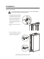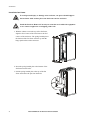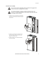
1
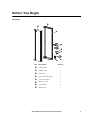
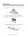
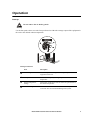
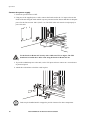
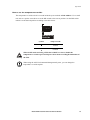
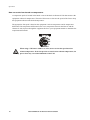
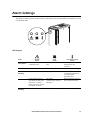
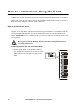
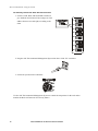
NetworkAIR ® Rack Air
Removal Unit
ACF102BLK
Installation
Contents
General Information . . . . . . . . . . . . . . . . . . . . . . . . . . . . . . . . . 1
Introduction . . . . . . . . . . . . . . . . . . . . . . . . . . . . . . . . . . . 1
Features . . . . . . . . . . . . . . . . . . . . . . . . . . . . . . . . . . . . . . 1
Safety Information. . . . . . . . . . . . . . . . . . . . . . . . . . . . . . . . . . . 2
Before You Begin . . . . . . . . . . . . . . . . . . . . . . . . . . . . . . . . . . . 3
Inventory . . . . . . . . . . . . . . . . . . . . . . . . . . . . . . . . . . . . . 3
Tools required . . . . . . . . . . . . . . . . . . . . . . . . . . . . . . . . . . 4
Receiving inspection . . . . . . . . . . . . . . . . . . . . . . . . . . . . . 4
Installation . . . . . . . . . . . . . . . . . . . . . . . . . . . . . . . . . . . . . . . . 5
Remove the rear doors . . . . . . . . . . . . . . . . . . . . . . . . . . . . 5
Install the fan frame . . . . . . . . . . . . . . . . . . . . . . . . . . . . . . 6
Install the fan assembly . . . . . . . . . . . . . . . . . . . . . . . . . . . 7
Optional Items . . . . . . . . . . . . . . . . . . . . . . . . . . . . . . . . . . . . . 8
Operation . . . . . . . . . . . . . . . . . . . . . . . . . . . . . . . . . . . . . . . . . 9
Start-up . . . . . . . . . . . . . . . . . . . . . . . . . . . . . . . . . . . . . . 9
Connect the power supply . . . . . . . . . . . . . . . . . . . . . . . . 10
How to set the fans based on wattage . . . . . . . . . . . . . . . . 11
Temperature override . . . . . . . . . . . . . . . . . . . . . . . . . . . . 11
How to set the temperature override . . . . . . . . . . . . . . . . . 13
How to set the fans based on temperature . . . . . . . . . . . . . 14
Alarm Settings. . . . . . . . . . . . . . . . . . . . . . . . . . . . . . . . . . . . . 15
LED legend
. . . . . . . . . . . . . . . . . . . . . . . . . . . . . . . . . . 15
How to Communicate Using the A-Link . . . . . . . . . . . . . . . . . . 16
How to connect to the A-Link . . . . . . . . . . . . . . . . . . . . . . 16
Warranty and Service . . . . . . . . . . . . . . . . . . . . . . . . . . . . . . . 19
Limited warranty . . . . . . . . . . . . . . . . . . . . . . . . . . . . . . . 19
Warranty limitations . . . . . . . . . . . . . . . . . . . . . . . . . . . . 19
Obtaining service . . . . . . . . . . . . . . . . . . . . . . . . . . . . . . 19
Rack Air Removal Unit Installation
i
Life-Support Policy . . . . . . . . . . . . . . . . . . . . . . . . . . . . . . . . . . 20
General policy . . . . . . . . . . . . . . . . . . . . . . . . . . . . . . . . 20
Examples of life-support devices . . . . . . . . . . . . . . . . . . . . 20
Specifications — ACF102BLK . . . . . . . . . . . . . . . . . . . . . . . . . . 21
ii
Rack Air Removal Unit Installation
General Information
Introduction
The American Power Conversion NetworkAIR® Rack Air Removal Unit removes heat generated by
the exhaust of equipment contained in a NetShelter VX or NetShelter EP EIA 19-inch enclosure. The
three fans provide increased air flow needed to cool densely-packed equipment and allow air to
bypass obstacles in the rear of the enclosure such as power and data cables. An optional duct kit
removes the heat entirely from the data center.
Features
Features of the Rack Air Removal Unit:
• Variable fan settings — based on power load and user-definable exhaust temperature
• Dual input connectors — for redundant power
• Three individually fused fans — allows unit to be used for redundancy or higher capacity
• Alarm LEDs — system status, fan status, and thermal control status
• Duct kit — for removal of heat from the air-conditioned space (optional)
• Integrated smoke detector (optional)
• APC Environmental Management System — for remote control and monitoring of the Rack Air
Removal Unit (optional)
NetworkAIR Rack Air Removal Unit Installation
1
Safety Information
For computer-room use only.
Warning
Install the Rack Air Removal Unit only on racks that are loaded with equipment,
counter-weighted, or stabilized to avoid tipping of the rack.
Inspect the Rack Air Removal Unit for damage before installation.
Disconnect power to the Rack Air Removal Unit before installing it into the rack.
Failure to do so may result in personal injury or damage to equipment.
Do not apply power to the unit until the installation is complete. The Rack Air
Removal Unit contains moving parts, which are potentially hazardous when
operated outside of the rack.
Do not attempt to move a heavily-loaded enclosure by yourself. Doing so
introduces risk of injury due to muscle strain or to tipping of the enclosure.
Fully-loaded enclosures require at least two people to move safely.
Do not attempt to install the Rack Air Removal Unit by yourself. Doing so
introduces risk of injury due to muscle strain or to tipping of the enclosure. The
Rack Air Removal Unit requires at least three people to install safely.
Check that the power cord plugs and sockets are in good condition before
installation.
Connect the Rack Air Removal Unit to 230V IEC C-13 outlet. The outlet must
be connected to appropriate branch circuit/mains protection (fuse or circuit
breaker). Connection to any other type of outlet may result in a shock hazard.
This equipment contains potentially hazardous voltages. Do not attempt to
disassemble the unit.
Always install and operate the Rack Air Removal Unit as shown in this manual.
Installing the Rack Air Removal Unit requires three people. Do not attempt to lift
the Rack Air Removal Unit without assistance.
Heavy
2
NetworkAIR Rack Air Removal Unit Installation
Before You Begin
Inventory
Item Description
Quantity
Fan assembly
1
Exhaust vent
1
Fan frame
1
Power cords (IEC 320)
2
5/32" hex wrench
1
M5 hex wrench
1
Cord retainer
2
Hinge screw
1
NetworkAIR Rack Air Removal Unit Installation
3
Before You Begin
Tools required
5/32" hex wrench
(provided)
M5 hex wrench
(provided)
i
Receiving inspection
Inspect the package and contents for shipping damage, and make sure that all parts were sent. Report
any damage immediately to the shipping agent, and report missing contents, damage, or other
problems immediately to APC or your APC reseller.
4
NetworkAIR Rack Air Removal Unit Installation
Installation
Remove the rear doors
To avoid personal injury or damage to the enclosure, one person should support
the door while another removes it from the frame.
Warning
1. If necessary, move the rack to allow
for at least 30 inches of clearance to
install the Rack Air Removal Unit.
2. Open the rear doors and pull down
on the spring-loaded hinge pin
attached to the top of the door. Lift
the door from its frame and set it
safely aside.
3. Repeat this step with the other rear
door.
4. Using the included M5 hex wrench,
remove the door bumpers at the top
and bottom of the door frame.
NetworkAIR Rack Air Removal Unit Installation
5
Installation
Install the fan frame
To avoid personal injury or damage to the enclosure, one person should support
the fan frame while another places the fan frame onto the enclosure.
Warning
Install the Rack Air Removal Unit only on racks that are loaded with equipment
or are counter-weighted to avoid tipping of the rack.
Warning
1. With the exhaust vent at the top of the fan frame,
align the four corners of the fan frame to the four
corners of the enclosure. The spring-loaded pins at
the bottom of the fan frame will line up with the
hinge-pin brackets on the enclosure.
2. Insert the spring-loaded pins at the bottom of the
fan frame into the holes.
3. Pull the spring-loaded pins at the top of the fan
frame and release the pins into the holes.
6
NetworkAIR Rack Air Removal Unit Installation
Installation
Install the fan assembly
To prevent the enclosure from tipping, all four pins must be in engaged in the
enclosure frame before installing the fan assembly.
Warning
Warning
To avoid personal injury or damage to the Rack Air Removal Unit or the
enclosure, two people should support the fan assembly while another places the
fan assembly onto the enclosure.
1. Align the lower pin with the hole in the hinge
pin bracket on the fan frame and insert the pin
into the hole.
2. Align the upper hinge hole with the hole in
the upper hinge pin bracket and insert the
hinge screw into the holes.
3. Tighten the hinge screw with the included
5/32" hex wrench.
NetworkAIR Rack Air Removal Unit Installation
7
Optional Items
American Power Conversion offers additional products (not included) for the Rack Air Removal
Unit:
• Smoke Detector Kit (ACF121) — mounting plate and smoke detector for use inside the Rack
Air Removal Unit.
• Air Duct Kit (ACF120) — for removal of heat from the air conditioned area. If using the
optional duct kit with the temperature setpoint mode, you will need to monitor the room
temperature for the first 24 hours, and adjust your setpoint to maintain the proper temperature
differential (see “How to set the fans based on temperature” on page 14).
• APC Environmental Management System (AP9320) — monitoring unit and A-Link
connections for monitoring and controlling the Rack Air Removal Unit from a remote location.
8
NetworkAIR Rack Air Removal Unit Installation
Operation
Start-up
Do not remove the air intake guards.
Warning
Use the fan speed selector to set the fan speed based on either the wattage output of the equipment in
the rack or the desired exhaust temperature.
kW
5
3
2
C
6
38
35
32
OFF 29.5
Fan Speed Selector
Item
Description
KW settings
Set the fan speed according to the wattage output of the
equipment in the rack.
Fan speed selector
Control the fan speed by wattage output or exhaust
temperature.
Exhaust temperature
settings
Set the Rack Air Removal Unit to set the fan speed based on
the exhaust temperature.
Remote Setting
Set the Rack Air Removal Unit to be controlled by a
connected APC Environmental Management System.
NetworkAIR Rack Air Removal Unit Installation
9
Operation
Connect the power supply
1. Set the fan speed selector to OFF.
2. Using one of the supplied power cords, connect the female end to the "A" input socket on the
inside of the unit. Plug the male end into a power-protected socket. Ensure that there is adequate
power for the fans to run at 100% (230V 4 A). The UPS in the rack must be sized properly to
power this unit.
Use the Rack Air Removal Unit only with a 3000 watt UPS or higher. The UPS
should not be loaded above 80% when using the Rack Air Removal Unit.
Warning
3. To provide redundant power to the unit, use the "B" input socket to connect to a second source
of protected power.
4. Attach the cord retainer to lock the cords in place.
Cords may be bundled and tie-wrapped to provide clearance for other components.
Note
10
NetworkAIR Rack Air Removal Unit Installation
Operation
To check operation of the unit:
5. Apply power to the fans by turning the fan speed selector from the OFF position to one of the
four exhaust temperature settings.
6. Make sure the fans are moving.
7. Turn off the power to the unit.
If no air is flowing from the Rack Air Removal Unit, check the power connection.
Note
How to set the fans based on wattage
Determine the wattage of your equipment and set the fan speed selector to the corresponding kW
setting.
\
kW
5
3
2
Warning
Note
Warning
6
C
38
35
32
OFF 29.5
Setting the kW setpoint too low could damage the equipment in the enclosure. If
the amount of kW in your enclosure falls between two of the numbers on the
setpoint dial, choose the higher number or set based on exhaust temperature.
When the temperature override is enabled and the temperature in the rack rises above
40.5° C (105° F), the Rack Air Removal Unit will automatically increase the fan speed
to bring the temperature below 40.5° C (105° F).
When in kW mode and using a UPS that is 3000VA or lower, disable the
temperature override to prevent the power draw from exceeding the limitations
of the UPS.
The UPS should not be loaded above 80% when using the Rack Air Removal
Unit.
Temperature override
The kW settings on the fan speed selector run the fans at a constant speed, while the exhaust
temperature settings adjust the fan speed depending on the exhaust temperature of the equipment in
the rack. The Rack Air Removal Unit is equipped with a temperature override that protects the
equipment in the rack while the unit is in kW mode. If the unit is in kW mode, and the exhaust
temperature rises above 40.5° C (105° F) (the override setpoint), the unit increases the fan speed to
remove excess heat from the rack.
NetworkAIR Rack Air Removal Unit Installation
11
Operation
Temperature Override in each Fan Speed Mode
kW mode
Exhaust temperature
mode
Remote mode
Temp Override
Enabled
Fan speed will increase
when rack equipment
exhaust temperature
reaches 40.5° C (105° F)
No Effect
Depends on the fan speed
selection of the remote
device. Same as kW or
exhaust temperature mode.
In kW mode the
temperature override
setpoint can be set to
32.2–51.6° C (90–125°
F)
Temp Override
Disabled
No Effect
No Effect
No Effect
Note
12
If a Computer Room Air Conditioner fails, the subsequent rise in ambient temperature
can cause the temperature override to activate. Increasing the fan speed can have an
impact on the airflow in the room.
NetworkAIR Rack Air Removal Unit Installation
Operation
How to set the temperature override
The temperature override switch is recessed inside the space marked A-Link Address. Use a small
tool such as a pocket screwdriver to set the DIP switch to the correct position. Set the DIP switch
labeled 1 to the desired position according to the table below.
1 2 3 4
Temperature
Override
Symbol
Temp Override
Enabled
Disabled
Warning
When in kW mode and using a UPS that is 3000VA or lower, disable the
temperature override to prevent the power draw from exceeding the limitations of
the UPS.
When using the APC Environmental Management System, you can change the
temperature override setpoint.
Note
NetworkAIR Rack Air Removal Unit Installation
13
Operation
How to set the fans based on temperature
A temperature probe is located in the intake vents of the Rack Air Removal Unit that measures the
equipment exhaust air temperature. The unit will increase or decrease the speed of the fans to keep
the equipment exhaust at the desired temperature.
The appropriate fan speed is based on the equipment’s inlet air temperature and its temperature
differential. The temperature differential is the rise in temperature between the inlet air and the
exhaust air after it passes through the equipment. Refer to your equipment manual to determine the
temperature differential.
.
kW
5
3
2
Warning
14
6
C
38
35
32
OFF 29.5
When using a UPS that is 3000VA or lower, do not set the fan speed based on
exhaust temperature. If the fan speed is set based on the exhaust temperature, the
power draw may exceed the limitations of the UPS.
NetworkAIR Rack Air Removal Unit Installation
Alarm Settings
The Rack Air Removal Unit has three LEDs on the front of the door that indicate whether the system
is in an alarm state.
LED legend
System
Status
LED
Fan
Status
Thermal Control
Status
Description
Indicates the status of the
controller boards
Indicates status of the three
fans
Indicates the status of the
temperature in the
enclosure
Green
System OK
Fans OK
Temperature within range
Green
Flashing
N/A
N/A
Exhaust temperature has
exceeded the temperature
override setpoint
(kW mode only)
Red
Control failure, the fans
will default to high speed
when there is a board
failure to keep air moving
through the enclosure
Fan failure,
remaining fans operate at
full speed
High temperature, the unit
has lost thermal control
Red/Green
Flashing
N/A
Smoke Alarm (optional)
Smoke Alarm (optional)
NetworkAIR Rack Air Removal Unit Installation
15
How to Communicate Using the A-Link
The Rack Air Removal Unit can be used with an APC Environmental Management System that can
monitor and control the unit. Connect the APC Environmental Management System any Rack Air
Removal Units by using the in and out A-Link connections.
How to connect to the A-Link
The Rack Air Removal Unit has two connections (IN and OUT) for linking several devices together
using the A-Link. The Rack Air Removal Unit must be given an address to communicate with the
APC Environmental Management System. The address DIP switch is recessed inside the space
marked A-Link Address. Use a small tool such as a pocket screwdriver to set the DIP switch to the
correct position.
Remove power from the Rack Air Removal Unit before setting DIP switches or
connecting other devices.
Warning
To remotely monitor the Rack Air Removal Unit:
1. Set the second, third, and fourth DIP switches to
give the Rack Air Removal Unit a unique A-Link
address between one and eight, according to the
chart.
1=
1
2
3
4
2=
3=
4=
5=
6=
7=
8=
16
NetworkAIR Rack Air Removal Unit Installation
1
2
3
4
1
2
3
4
1
2
3
4
1
2
3
4
1
2
3
4
1
2
3
4
1
2
3
4
1
2
3
4
How to Communicate Using the A-Link
2. Plug the device into the A-Link “IN” connector.
3. Set the fan speed selector to the desired exhaust temperature or enclosure wattage.
kW
5
3
2
6
C
38
35
32
OFF 29.5
The APC Environmental Management System will be able to monitor the temperature and the alarms
on the Rack Air Removal Unit.
NetworkAIR Rack Air Removal Unit Installation
17
How to Communicate Using the A-Link
To remotely control the Rack Air Removal Unit:
1. Set the second, third, and fourth DIP switches to
give the Rack Air Removal Unit a unique A-Link
address between one and eight, according to the
chart.
1=
1
2
3
4
2=
3=
4=
5=
6=
7=
8=
1
2
3
4
1
2
3
4
1
2
3
4
1
2
3
4
1
2
3
4
1
2
3
4
1
2
3
4
1
2
3
4
2. Plug the APC Environmental Management System into the A-Link “IN” connector.
3. Set the fan speed selector to Remote.
kW
5
3
2
6
C
38
35
32
OFF 29.5
Use the APC Environmental Management System to control the temperature in the rack and to
monitor the Rack Air Removal Unit for any alarms.
18
NetworkAIR Rack Air Removal Unit Installation
Warranty and Service
Limited warranty
APC warrants the Rack Air Removal Unit to be free from defects in materials and workmanship for a
period of two years from the date of purchase. Its obligation under this warranty is limited to
repairing or replacing, at its own sole option, any such defective products. This warranty does not
apply to equipment that has been damaged by accident, negligence, or misapplication or has been
altered or modified in any way. This warranty applies only to the original purchaser.
Warranty limitations
Except as provided herein, APC makes no warranties, express or implied, including warranties
of merchantability and fitness for a particular purpose. Some jurisdictions do not permit
limitation or exclusion of implied warranties; therefore, the aforesaid limitation(s) or exclusion(s)
may not apply to the purchaser.
Except as provided above, in no event will APC be liable for direct, indirect, special, incidental,
or consequential damages arising out of the use of this product, even if advised of the possibility
of such damage.
Specifically, APC is not liable for any costs, such as lost profits or revenue, loss of equipment, loss of
use of equipment, loss of software, loss of data, costs of substitutes, claims by third parties, or
otherwise. This warranty gives you specific legal rights and you may also have other rights, which
vary according to jurisdiction.
Obtaining service
To obtain support for problems with your Rack Air Removal Unit:
0
1. Note the serial number and date of purchase. This is found on the back of the Fan Assembly.
2. Contact Customer Support at a phone number on the back cover of this document. A technician
will try to help you solve the problem by phone.
3. If you must return the product, the technician will give you a return material authorization
(RMA) number. If the warranty expired, you will be charged for repair or replacement.
4. Pack the unit carefully. The warranty does not cover damage sustained in transit. Enclose a
letter with your name, address, RMA number and daytime phone number; a copy of the sales
receipt; and a check as payment, if applicable.
5. Mark the RMA number clearly on the outside of the shipping carton.
6. Ship by insured, prepaid carrier to the address provided by the Customer Support technician.
There are no customer serviceable items on the Rack Air Removal Unit. Do not attempt to open or
repair the Rack Air Removal Unit.
NetworkAIR Rack Air Removal Unit Installation
19
Life-Support Policy
General policy
American Power Conversion (APC) does not recommend the use of any of its products in the
following situations:
• In life-support applications where failure or malfunction of the APC product can be reasonably
expected to cause failure of the life-support device or to affect significantly its safety or
effectiveness.
• In direct patient care.
APC will not knowingly sell its products for use in such applications unless it receives in writing
assurances satisfactory to APC that (a) the risks of injury or damage have been minimized, (b) the
customer assumes all such risks, and (c) the liability of American Power Conversion is adequately
protected under the circumstances.
a
Examples of life-support devices
The term life-support device includes but is not limited to neonatal oxygen analyzers, nerve
stimulators (whether used for anesthesia, pain relief, or other purposes), autotransfusion devices,
blood pumps, defibrillators, arrhythmia detectors and alarms, pacemakers, hemodialysis systems,
peritoneal dialysis systems, neonatal ventilator incubators, ventilators (for adults and infants),
anesthesia ventilators, infusion pumps, and any other devices designated as “critical” by the U.S.
FDA.
Hospital-grade wiring devices and leakage current protection may be ordered as options on many
APC UPS systems. APC does not claim that units with this modifications are certified or listed as
hospital-grade by APC or any other organization. Therefore these units do not meet the requirements
for use in direct patient care.
a
20
NetworkAIR Rack Air Removal Unit Installation
Specifications — ACF102BLK
230VAC; 50Hz
Electrical
Power source
230VAC; 50Hz
Rated current
4A
Compliance
VDE
Physical
Physical dimensions of fan assembly—h × w × d
193.55×60.78×17.78cm
76.20×23.93×7.0in
Net weight—unit only
65.77kg (145lb)
Shipping weight
95.27kg (210lb)
Shipping dimensions
74.93×59.69×205.74cm
(29.5×23.5×81in)
Airflow
(non ducted)
2kW
9.06 m3/min (320 CFM)
3kW
13.59 m3/min (480 CFM)
5kW
22.65 m3/min (800 CFM)
6.25kW
28.32 m3/min (1000 CFM)
NetworkAIR Rack Air Removal Unit Installation
21
APC Worldwide Customer Support
Customer support for this or any other APC product is available at no charge in any of the following ways:
• Visit the APC Web site to find answers to frequently asked questions (FAQs), to access documents
in the APC Knowledge Base, and to submit customer support requests.
– www.apc.com (Corporate Headquarters)
Connect to localized APC Web sites for specific countries, each of which provides customer
support information.
– www.apc.com/support/
Global support with FAQs, knowledge base, and e-support.
• Contact an APC Customer Support center by telephone or e-mail.
– Regional centers:
APC headquarters U.S., Canada
(1)(800)800-4272 (toll free)
Latin America
(1)(401)789-5735 (USA)
Europe, Middle East, Africa
(353)(91)702020 (Ireland)
Japan
(0) 35434-2021
– Local, country-specific centers: go to www.apc.com/support/contact for contact information.
Contact the APC representative or other distributor from whom you purchased your APC product for
information on how to obtain local customer support.
To obtain a repair authorization number for a NetworkAIR product, call APC NetworkAIR technical
services between 8:00 A.M. and 5:00 P.M. Eastern time, Monday through Friday:
• Phone: (1)(888)695-6500 (USA and Canada, toll free)
• Fax: (1)(401)788-2691
Entire contents copyright © 2003 American Power Conversion. All rights reserved.
Reproduction in whole or in part without permission is prohibited. APC, the APC logo,
NetworkAIR, and InfraStruXure are trademarks of American Power Conversion Corporation
and may be registered in some jurisdictions. All other trademarks, product names, and
corporate names are the property of their respective owners and are used for informational
purposes only.
990-1575
05/2003