1
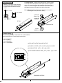
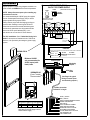
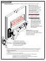
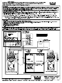
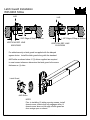
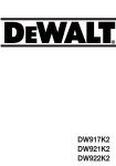
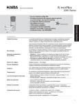
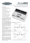
INSTALLATION INSTRUCTIONS
DE5000 & DE9000 SERIES
DELAYED EGRESS EXIT DEVICE
Note: Refer to Individual Series Installation Instructions for templating and installation of device; @ www.dorma-usa.com
These are additional instructions for installation and operation of the "Delayed Egress" unit.
Specifications
DE5300
DE9300
RIM
85 Decibel Alarm - Standard
LED Status Indicator - Standard
Nuisance Alarm - Standard
Key Switch Control - Standard
Remote Authorized Egress - Standard
Remote Re-Arm - Standard
Remote Bypass - Standard
Door Position Input - Standard, DIP Switch Setting
Auto Reset or Manual Reset, DIP Switch Setting
Auto - Stanadard (Manual - in CA)
Additional Form "C" Relays For Optional Horn etc.
(Rated 1 amp @ 30 vdc)
DE5500
DE9500
MORTISE
DE5100
DE9100
CONCEALED VERTICAL ROD
REQUIRES DORMA ES-100 or AD100 POWER SUPPLY.
Easily accessible slide in and out electronics.
Meets UL, ANSI/BHMA & CBC requirements.
SIZE A: (DE9000 Series)
Will fit 48" (1219 mm) door opening without cutting.
Can be cut to fit a 40 1/2" (1029 mm) minimum door opening.
SIZE B: (DE9000 Series)
Will fit 36" (914 mm) door opening without cutting.
Can be cut to fit a 34 1/2" (876 mm) minimum door opening.
SIZE AA: (DE5000 Series w/ #443 strike)
Will fit 48" (1219 mm) door opening without cutting.
Can be cut to fit a 38 3/4" (984 mm) minimum door opening.
SIZE BB: (DE5000 Series w/ #443 strike)
Will fit 36" (914 mm) door opening without cutting.
Can be cut to fit a 31 3/4" (806 mm) minimum door opening.
Assembly
NOTE:
If cutting to length is required
carefully remove filler and
electronics for cutting. Use all
grounding precautions.
Mortise Cylinder
(factory supplied)
Pt. No. 90B10SC118
End Cap Bracket
End Cap
WIRE PIG TAIL
Connecting Plugs
Touchbar/Rail
Assembly
(Delayed Egress)
Filler (DE9000/DE5000)
NOTE: "Always disconnect power prior to making
any connections or service!"
Observe proper static discharge grounding procedures
when installing or servicing the Delayed Egress device.
1135-88
95011817
1
IDE - 12 8/09
Cylinder Specification
To Change Cylinder: Carefully remove filler from rail. Unscrew cylinder
nut, remove actuator and replace cylinder. Spacer required for cylinders
over 1 1/8". Insert cylinder as shown, re-install actuator & secure with
cylinder nut. Do not over tighten. Re-install filler in rail and reconnect the
small pigtail connectors. Use caution not to pinch or bind wires.
Standard 1 1/8" mortise cylinder, randomly
keyed supplied by factory. Spacer required
for longer cylinder such as when using an
IC core.
Note: If DIP switch settings required to be changed, do it now prior to
re-installing filler in rail. (See Section below.)
5/16" - 11/32"
1 1/8" Standard
Cylinder Nut
4000-167-501
(6310D)
CAM
Actuator-DE
95055525
21/32"
DE Filler
Underside of Filler
Cylinder
90B10SC118
DIP Switch Setting
DIP switch settings should be completed at time of initial installation;
check local building code. Factory settings are as follows:
1 - ON - NOT ACTIVE
2 - OFF - LOCKED
3 - ON - 3 SECONDS
4 - OFF - 10 SECONDS
(1) DPS: (OFF) ACTIVE (ON) NOT ACTIVE
(2) POWER UP STATE: (OFF) LOCKED (ON) UN-LOCKED
(3) NUISANCE TIME: (OFF) 1 SEC. (ON) 3 SEC.
(4) AUTHORIZED EGRESS TIME: (OFF) 10 SEC. (ON) 20 SEC.
1
ON
OFF
Underside of Filler
2
2
3
4
Basic wire connection
DORMA MODEL ES100
24 VOLT DC POWER SUPPLY
Specific project or custom wiring diagrams available on request, consult the DORMA techinical service department.
NOTE: Always disconnect power prior to making any
connections or service.
It is recommended that the 120VAC power be supplied
from an Uninterrupted Power Supply (UPS) to ensure
proper operation during a power failure.
Always observe proper static discharge grounding procedure's when installing or servicing the DE device.
Wires that interconnect the remote authorized egress
and remote by-pass/rearm must be located within the
same room as the panic hardware (DE), or outside the door at no more than 10' feet of distance.
PUSH
TO RESET
FUSE
(AD100 220V Version Optional)
CIRCUIT
BREAKER
3.0 AMP
24VDC
3/4 AMP
120VAC
REPLACE WITH 3AG 3/4 AMP
SLO-BLOW TYPE FUSE ONLY
ZONE 1
ZONE 2
OUTPUT
CONTROL
TERMINALS
SWITCH
24VDC
(+)
(+)
(-) (IN)
1
2
3
4
NO
OUTPUT
CONTROL
TERMINALS
SWITCH
24VDC
(+)
(+)
(-) (IN)
5
6
7
8
TO
N.C. CONTACTS
IN FIRE ALARM
CONTROL PANEL.
For ULC installations: Some "Authorities Having Jurisdiction" also require an illumination level of 100' feet at
the door, to be provided by the emergency power supply
system.
CONNECTION
9
10
11
12
Green Ground
Screw Located
On Chassis
CAUTION:
TURN OFF 120VAC POWER PRIOR TO MAKING ANY CONNECTIONS TO TERMINALS
DORMA ES100
WHITE (NEUTRAL)
BLACK (HOT)
GREEN (GROUND)
Minimum 18 AWG
wire recommended for
24VDC inputs (red &
black) leads.
120 VAC
From UPS
POWER LINE Power Source
(1.0 AMP MAX.)
Control Inputs
Monitoring
Outputs
Grey
DPS Black
DORMA ES105
(Power Transfer)
"Recommended"
(See Page 6 for typical
wiring of control inputs
and monitoring outputs.)
(12) Wire Connection
Bundle 22" in length.
BLACK: (-) 24VDC IN
RED: (+) 24VDC IN
WHITE: AUTHORIZED EGRESS/AUTO RESET
ORANGE: BYPASS/RE-ARM
GREY: DPS N/C
VIOLET: ALARM RELAY COMMON
GREEN: RED OUTPUT EMITTER
BROWN: RED OUTPUT COLLECTOR
BLUE: GREEN OUTPUT EMITTER
YELLOW: GREEN OUTPUT COLLECTOR
PINK: ALARM RELAY N/C
TAN: ALARM RELAY N/O
Maximum Wire Length From Power Supply To
Device & Back To Supply In Feet x Wire Gage/Size
WIRE 18AWG
FEET
25
16AWG
50
14AWG 12AWG
75
100
* For 24VDC inputs only (red & black wires).
Note: Wire run is from supply to device
and back to the supply.
3
Key switch operation for device.
Delayed Egress Mode: Unit is armed and touch bar will not activate the latchbolt. (LED is solid green,
audible alarm is off). Initiated after power up, (DIP switch #2 in OFF position) authorized egress mode
or re-arm mode.
Nuisance Alarm Mode: Unit is armed and touch bar will not activate the latch bolt. (LED is solid green,
audible alarm sounds a short tone) DIP switch selectable for 1 or 3 seconds. (See page 2) Initiated by
depressing touch bar.
Delay Mode: Unit is armed and touch bar will not activate the latch bolt. (LED is solid yellow, audible alarm
sounds intermittent tone). Unit remains in the delay mode for 15 seconds ( including nuisance time).
Initiated by holding the touch bar depressed past the nuidance alarm time (30 second delay mode option
available.) Once started, the delay mode is irreversible and automatically initiates the alarm mode.
Alarm Mode: Unit is disarmed and touch bar will activate the latch bolt (LED is solid red, audible alarm
sounds continous tone). Initiated automatically from the delay mode and is irreversible. Unit remains in
the alarm mode until manually reset with key.
By-Pass Mode: From the delayed egress mode; unit is continuously disarmed and touch bar will activate
the latch bolt (LED slowly flashes green, audible alarm is off). Initiated by rotating the key clockwise until
switch activates (approximately 180 degrees). DPS input is disabled.
Re-arm Mode: From alarm mode; unit goes to the delayed egress mode. Initiated by rotating the key
clockwise until switch activates (approximately 180 degrees). From the bypass mode; unit goes to the
delayed egress mode. Initiated by rotating the key clockwise until the switch activates (approximately
180 degrees.) The LED will return to solid green.
Bypass/Re-arm
Rotate Clock-wise
Authorized Egress Mode: Unit is disarmed for 10 or 20 seconds (DIP switch selectible) and touch bar
will activate the latch bolt (LED quickly flashes green, audible alarm is off). After the authorized egress
time unit returns to the delayed egress mode automatically. The authorized egress mode is initiated by
rotating the key counter-clockwise until switch activates (approximately 180 degrees). DPS input will not
initiate during the 10 or 20 second egress time, but will terminate the egress time if the DPS closes
before the end of the egress time. DPS input will initiate an alarm after the 10 or 20 second egress time,
if the DPS is opened.
Rotate Counter Clock-wise
Authorized Egress
NOTE: The By-pass mode and Re-arm mode (orange wire) may be intiated externally from the terminal
connector. (Normally open dry contact to ground.) The Authorized Egress mode (white wire) may be
initiated externally from the terminal connector (Normally open dry contact to ground). See page 6 for
addtional details.
4
Cover, end cap and label
After all wire connections are made and device checked for operation, install the chassis cover, end cap
and label as shown below.
NOTE: Compliance with the
California Building Code (CBC)
requires different label then supplied.
The CBC label is shown below. If
required, order through Service Parts,
model number CBCLBL.
Consult with local code & "authority's
having jurisdiction". See CBC
Secton 1003.1.10 Paragraph 6.
KEEP PUSHING. THIS DOOR
WILL OPEN IN 15 SECONDS.
ALARM WILL SOUND.
NOTE: To enable the device
to power up in the unarmed
mode, set Dip switch #2 in the
"ON" position. A green blinking
light will appear. Device will
required to be manually armed
with a key at the device or
from the remote console.
(See page 4 under rearm mode,
for key operation.)
LED light codes:
Solid Green - Delayed Egress Mode
Slow Flashing Green - Bypass Mode
Fast Flashing Green - Authorized Egress Mode
Solid Yellow - Delay Mode
Solid Red - Alarm Mode
Latch
guard
For added security a latch guard
is supplied with the delayed egress
Strike & Latch
device. Install along with the standard
Guard Installation.
#463 strike as shown. Correct reference
dimension of 2 3/8" from edge of stop
or mullion must be maintained.
#463
strike
It is recommended that the following routine maintenance checks be performed at intervals of not less
than once a month, and as a requirement by the local authority having jurisdiction, by the occupant or
his approved representative:
a) Inspect and operate the panic device to ensure that all components are in satisfactory working
conditon.
b) Ensure that all strikes are free from obstruction.
c) Ensure that the fire alarm system and electronic function of device are in working order.
This product meets or exceeds the following standards:
ANSI/BHMA 156.3, CBC Section 1003.1.10, California State Fire Marshal,
NFPA 80 &101 and UL Listed FWAX, FWAX7
5
REMOTE CONTROL & MONITORING INPUT
DORMA CC-400-D CONTROL CONSOLE
SWITCH MOMENTARY-RESET-MOMENTARY
Typical Diagram
(EXT.)
ALARM
(LED ON CONTROL PANEL WILL EMIT
SAME COLOR STATUS AS DE9000 DEVICE)
UP
COMMON
DPS
NC
DOWN
RED
YELLOW
GREEN
RETURN
(EXT.)
DOOR
SECURE
LIGHT
TAN
PINK
GRAY
VIOLET
GREEN
BROWN
BLUE
YELLOW
ORANGE
WHITE
BLACK
FROM 24VDC +
RED
Typical Diagram
REMOTE CONTROL INPUT
DORMA K708 KEYSWITCH
AUTHORIZED EGRESS
MO (LEFT)
BY PASS
MA (RIGHT)
BLACK
ORANGE
WHITE
6
FROM DE9000
FROM
DE9000
EXIT
DEVICE
Latch Guard Installation
With #463 Strike
LHR
LHR
1 5/8" Edge of Stop or Mullion
2 3/8" Edge of Stop or Mullion
VERTICAL REF. LINE
9300/F9300
VERTICAL REF. LINE
5300/F5300
For added security a latch guard is supplied with the delayed
egress device. Install the latch guard along with the standard
#463 strike as shown below. If (2) shims supplied are required
to meet correct reference dimension the latch guard is the same
thickness as (1) shim.
Latch Guard
#463 Strike
NOTE:
Prior to installing (2) strike securing screws, install
chassis cover, ensure bolt fully engages strike, &
chassis cover does not hit edge of latch guard as
door swings open or closed.
95037043
www.dorma-usa.com 1-800-523-8483
I463LG 8/09