1
SIEMENS Business Class
5890
DSL Router
User’s Guide
Part No. 107-5890-001
Software License and Limited Warranty
Copyright© 2005 Siemens Home and Office Communications Devices LLC. All rights reserved. Siemens and the Siemens logo are trademarks of Siemens AG,
Germany. All other trademarks are held by their respective companies. Siemens reserves the right to make changes to product specifications at any time without
notice.
SIemens Subscriber Networks LLC – End User Software License and Warranty
INSTALLATION OF THE HARDWARE AND SOFTWARE PROVIDED BY SIEMENS SUBSCRIBER NETWORKS, INC (SSN). CONSTITUTES ACCEPTANCE BY
YOU OF THE TERMS OF THE FOLLOWING SOFTWARE LICENSE AND LIMITED WARRENTY. IF YOU DO NOT ACCEPT THESE TERMS, PLEASE RETURN
THE HARDWARE AND SOFTWARE AND SOFTWARE IN ITS ORIGINAL PACKAGING TO THE VENDOR FROM WHICH YOU PURCHASED IT FOR A FULL
REFUND OF THE PURCHASE PRICE.
The following describes your license to use the software (the"Software") that has been provided with your Siemens customer premise equipment ("Hardware") and
the limited warranty that Siemens Subscriber Networks provides on its Software and Hardware. Siemens Subscriber Networks reserves any right not expressly
granted to the end user.
Software License
The Software is protected by copyright laws and international copyright treaties. The Software is licensed and not sold to you. The definition of Software includes, but
not limited to, system and operating software marketed by Siemens Subscriber Networks, including firmware, embedded software, software provided on media,
downloadable software, software for configuration or programmable logic elements, and all Siemens Subscriber Networks maintenance and diagnostic tools
associated with the above mentioned software. Accordingly, while you own the media (such as CD ROM or floppy disk) on which the software is recorded, Siemens
Subscriber Networks or its licensors retains ownership of the Software itself.
1. Grant of License. You may install and use one (and only one) copy of the Software in conjunction with the Siemens Subscriber Networks provided Hardware.
You may make backup copies of the system configuration as required. If the Hardware is being installed on a network, you may install the Software on the network
server or other server-side devise on which the Hardware is being installed and onto the client-side devices.
2. Restrictions. The license granted is a limited license. You may NOT:
• sublicense, assign, or distribute copies of the Software to others;
• decompile, reverse engineer, disassemble or otherwise reduce the Software or any part thereof to a human perceivable form;
• modify, adapt, translate or create derivative works based upon the Software or any part thereof; or
• rent, lease, loan or otherwise operate for profit the Software.
2. Transfer. You may transfer the Software only where you are also transferring the Hardware. In such cases, you must remove all copies of the Software from any
devices onto which you have installed it, and must ensure that the party to whom you transfer the Hardware receives this License Agreement and Limited Warranty.
3. Upgrades Covered. This License covers the Software originally provided to you with the Hardware, and any additional software that you may receive from
Siemens Subscriber Networks, whether delivered via tangible media (CD ROM or floppy disk), down loaded from Siemens Subscriber Networks, or delivered
through customer support. Any such additional software shall be considered "Software" for all purposes under this License.
4. Export Law Assurances. You acknowledge that the Software may be subject to export control laws and regulations of the U.S.A. You confirm that you will not
export or re-export the Software to any countries that are subject to export restrictions.
5. No Other Rights Granted. Other than the limited license expressly granted herein, no license, whether express or implied, by estoppel or otherwise, is granted
to any copyright, patent, trademark, trade secret, or other proprietary rights of Siemens Subscriber Networks or its licensors.
6. Termination. Without limiting Siemens Subscriber Networks’s other rights, Siemens Subscriber Networks may terminate this license if you fail to comply with any
of these provisions. Upon termination, you must return the Software and all copies thereof.
Limited Warranty
The following limited warranties provided by Siemens Subscriber Networks extend to the original end user of the Hardware/licensee of the Software and are not
assignable or transferable to any subsequent purchaser/licensee.
1. Hardware. Siemens Subscriber Networks warrants that the Hardware will be free from defects in materials and workmanship and will perform substantially in
compliance with the user documentation relating to the Hardware for a period of one year from the date the original end user received the Hardware.
2. Software. Siemens Subscriber Networks warrants that the Software will perform substantially in compliance with the end user documentation provided with the
Hardware and Software for a period of ninety days from the date the original end user received the Hardware and Software. The end user is responsible for the
selection of Hardware and Software used in the end user’s network. Given the wide range of third-party hardware and applications, Siemens Subscriber Networks
does not warrant the compatibility or uninterrupted or error free operation of our Software with the end user’s systems or network.
3. Exclusive Remedy. Your exclusive remedy and Siemens Subscriber Networks’s exclusive obligation for breach of this limited warranty is, in Siemens Subscriber
Networks’s sole option, either (a) a refund of the purchase price paid for the Hardware/Software or (b) repair or replacement of the Hardware/Software with new
or remanufactured products. Any replacement Hardware or Software will be warranted for the remainder of the original warranty period or thirty days, which ever
is longer.
4. Warranty Procedures. If a problem develops during the limited warranty period, the end user shall follow the procedure outlined below:
A.Prior to returning a product under this warranty, the end user must first call Siemens Subscriber Networks at (888) 286-9375, or send an email to Siemens
Subscriber Networks at [email protected] to obtain a return materials authorization (RMA) number. RMAs are issued between 8:00 a.m. and 5:00 p.m.
Central Time, excluding weekends and holidays. The end user must provide the serial number(s) of the products in order to obtain an RMA.
B.After receiving an RMA, the end user shall ship the product or defective component, including power supplies and cable, where applicable, freight or postage
prepaid and insured, to Siemens Subscriber Networks at 4849 Alpha Road, Dallas Texas 75244, U.S.A. Within five (5) days notice from Siemens Subscriber
Networks, the end user shall provide Siemens Subscriber Networks with any missing items or, at Siemens Subscriber Networks’s sole option, Siemens
Subscriber Networks will either (a) replace missing items and charge the end user or (b) return the product to the end user freight collect. The end user shall
include a return address, daytime phone number and/or fax. The RMA number must be clearly marked on the outside of the package.
C.Returned Products will be tested upon receipt by Siemens Subscriber Networks. Products that pass all functional tests will be returned to the end user.
D.Siemens Subscriber Networks will return the repaired or replacement Product to the end user at the address provided by the end user atSiemens Subscriber
Networks’s expense. For Products shipped within the United States of America, Siemens Subscriber Networks will use reasonable efforts to ensure delivery
within five (5) business days from the date received by Siemens Subscriber Networks. Expedited service is available at additional cost to the end user.
E.Upon request from Siemens Subscriber Networks, the end user must prove the date of the original purchase of the product by a dated bill of sale or dated
itemized receipt.
5. Limitations.
• The end user shall have no coverage or benefits under this limited warranty if the product has been subject to abnormal use, abnormal conditions, improper
storage, exposure to moisture or dampness, unauthorized modifications, unauthorized repair, misuse, neglect, abuse, accident, alteration, improper installation,
or other acts which are not the fault of Siemens Subscriber Networks, including acts of nature and damage caused by shipping.
• Siemens Subscriber Networks will not honor, and will not consider the warranty voided, if: (1) the seal or serial number on the Product have been tampered
with or (2) there has been any attempted or actual repair or modification of the Product by anyone other than an Siemens Subscriber Networks authorized
service provider.
• The limited warranty does not cover defects in appearance, cosmetic, decorative or structural items, including framing, and any non-operative parts.
• Siemens Subscriber Networks’s limit of liability under the limited warranty shall be the actual cash value of the product at the time the end user returns the
product for repair, determined by the price paid by the end user for the product less a reasonable amount for usage.Siemens Subscriber Networks shall not be
liable for any other losses or damages.
• The end user will be billed for any parts or labor charges not covered by this limited warranty. The end user will be responsible for any expenses related to
reinstallation of the product.
• THIS LIMITED WARRENTY IS THE ONLY WARRENTY SSN MAKES FOR THE PRODUCT AND SOFTWARE. TO THE EXTENT ALLOWED BY LAW, NO
OTHER WARRENTY APPLIES, WETHER EXPRESS, IMPLIED OR STATUTORY, INCLUDING ANY WARRENTY OF MERCHANTABILITY OR FITNESS
FOR A PARTICULAR PURPOSE.
6. Out of Warranty Repair. Out of warranty repair is available for a fixed fee. Please contact Siemens Subscriber Networks at the numbers provided above to
determine out of warranty repair rate. End users seeking out of warranty repair should contact Siemens Subscriber Networks as described above to obtain an RMA
and to arrange for payment of the repair charge. All shipping charges will be billed to the end-user.
General Provisions
The following general provisions apply to the foregoing Software License and Limited Warranty.
1. No Modification. The foregoing Limited Warranty is the end user’s sole and exclusive remedy and is in lieu of all other warranties, express or implied. No oral or
written information or advice given by Siemens Subscriber Networks or tis dealers, distributors, employees or agents shall in any way extend, modify or add to
the foregoing Software License and Limited Warranty. This Software License and Limited Warranty constitutes the entire agreement between Siemens Subscriber
Networks and the end user, and supersedes all prior and contemporaneous representation, agreements or understandings, oral or written. This Software License
and Limited Warranty may not be changed or amended except by a written instrument executed by a duly authorized officer of Siemens Subscriber Networks.
Siemens Subscriber Networks neither assumes nor authorizes any authorized service center or any other person or entity to assume for it any other obligation or
liability beyond that which is expressly provided for in this Limited Warranty including the provider or seller of any extended warranty or service agreement.
The Limited Warranty period for Siemens Subscriber Networks supplied attachments and accessories is specifically defined within their own warranty cards and
packaging.
2. EXCLUSION OF INCIDENTAL, CONSEQUENTIAL AND OTHER DAMAGES. TO THE FULL EXTENT PERMITTED BY LAW, IN NO EVENT SHALL SSN OR
ITS LICENSORS BE LIABLE, WHETHER UNDER CONTRACT, WARRENTY, TORT OR ANY OTHER THEORY OF LAW FOR ANY SPECIAL, INCIDENTAL
OR CONSEQUENTIAL DAMAGES WHATSOEVER, INCLUDING BUT NOT LIMITED TO DAMAGES FOR LOSS OF PROFITS, BUSINESS INTERRPUTION,
PERSONAL INJURY, LOSS OR IMPAIRMENT OF DATA OR BUSINESS INFORMATION, EVEN IF SSN HAS BEEN NOTIFIED OF THE POSSIBILITY OF
SUCH DAMAGES. SSN’S OR IT’S LICENSOR’S LIABILITY TO YOU (IF ANY) FOR ACTUAL DIRECT DAMAGES FOR ANY CAUSE WHATSOEVER, AND
REGARDLESS OF THE FORM OF THE ACTION, WILL BE LIMITED TO, AND SHALL NOT EXCEED, THE AMOUNT PAID FOR THE HARDWARE/
SOFTWARE.
3. General. This Software License and Limited Warranty will be covered by and construed in accordance with the laws of the State of Texas, United States (excluding
conflicts of laws rules), and shall insure to the benefit of Siemens Subscriber Networks and its successor, assignees and legal representatives. If any provision of
this Software License and Limited Warranty is held by a court of competent jurisdiction to be a invalid or unenforceable to any extent under applicable law, that
provision will be enforced to the maximum extent permissible, and the remaining provisions of this Software License and Limited Warranty will remain in full force
and effect. Any notices or other communications to be sent to Siemens Subscriber Networks must be mailed by certified mail to the following address:
Siemens Subscriber Networks LLC
4849 Alpha Road
Dallas, TX 75244
U.S.A.
Attn: Customer Service
SIEMENS 5890 DSL Router
User’s Guide
Table of Contents
Chapter 1 Product Specifications
Front Panel ......................................................................................................................................................... 1
Back Panel ......................................................................................................................................................... 1
Hardware Specifications..................................................................................................................................... 2
Physical Specifications................................................................................................................................. 2
Operational Environment ............................................................................................................................. 2
Power Requirements.................................................................................................................................... 2
Processor ..................................................................................................................................................... 2
LAN Interface ............................................................................................................................................... 2
WAN Interface.............................................................................................................................................. 2
Serial Interface ............................................................................................................................................. 2
Software Specifications ...................................................................................................................................... 3
Configuration Management.......................................................................................................................... 3
Differentiated Services - Quality of Service provisioning ............................................................................. 3
Dial Backup .................................................................................................................................................. 3
Routing......................................................................................................................................................... 3
..................................................................................................................................................................... 3
IP Address Translation................................................................................................................................. 3
..................................................................................................................................................................... 3
ATM.............................................................................................................................................................. 4
Frame Relay................................................................................................................................................. 4
PPP (RFC 1661, RFC 2364)........................................................................................................................ 4
Security ........................................................................................................................................................ 4
Chapter 2 Installation
Installation Requirements ................................................................................................................................... 5
Package Contents........................................................................................................................................ 5
PC Requirements......................................................................................................................................... 5
Network Service Provider Requirements ..................................................................................................... 6
Hardware Installation.......................................................................................................................................... 7
PC Configuration ................................................................................................................................................ 8
Windows 98/ME ........................................................................................................................................... 8
Windows NT 4.............................................................................................................................................. 9
Windows 2000............................................................................................................................................ 10
Windows XP............................................................................................................................................... 11
Mac OS 9.x ................................................................................................................................................ 12
Mac OSX.................................................................................................................................................... 13
Linux........................................................................................................................................................... 14
Configuring the Router ..................................................................................................................................... 15
Establish Connection ................................................................................................................................. 15
Router Information Page ............................................................................................................................ 16
Chapter 3 Easy Setup
Access Easy Setup Wizard .............................................................................................................................. 17
Select Protocol ................................................................................................................................................. 17
SIEMENS
i
SIEMENS 5890 DSL Router
User’s Guide
Point-to-Point Protocol over ATM (VC Multiplexing) .................................................................................. 18
Point-to-Point Protocol over ATM (LLC Encapsulation) ............................................................................. 20
RFC 1483 (Multiprotocol Encapsulation LLC/SNAP) ................................................................................. 22
RFC 1483 (VC Multiplexing Routed).......................................................................................................... 23
Point-to-Point Protocol over Ethernet over RFC1483 ................................................................................ 24
RFC 1483 MAC Encapsulated Routing (MER) .......................................................................................... 25
RAW IP ...................................................................................................................................................... 26
Dynamic Host Configuration Protocol ........................................................................................................ 27
Local Area Network Configuration ............................................................................................................. 28
Chapter 4 User Setup
User Management ............................................................................................................................................ 29
Adding/Modifying A User Account.............................................................................................................. 30
Deleting A User Account ............................................................................................................................ 31
User Lookup............................................................................................................................................... 32
Secure Mode Configuration ....................................................................................................................... 33
Configure the Radius Server...................................................................................................................... 34
Configure the TacPlus Server .................................................................................................................... 35
Management Classes ................................................................................................................................ 36
Change Password ............................................................................................................................................ 37
Access Control ................................................................................................................................................. 38
Chapter 5 Advanced Setup
WAN Selection ................................................................................................................................................. 40
Remote File Configuration................................................................................................................................ 41
DMZ.................................................................................................................................................................. 42
Router Clock..................................................................................................................................................... 44
DHCP ............................................................................................................................................................... 45
QoS .................................................................................................................................................................. 47
Differentiated Services Framework ............................................................................................................ 47
Weighted Fair Queuing .............................................................................................................................. 47
Configure QoS Policy................................................................................................................................. 49
Reorder QoS Policies................................................................................................................................. 51
Routing Table Configuration............................................................................................................................. 52
Dial Backup ...................................................................................................................................................... 53
ATM Traffic Shaping......................................................................................................................................... 54
Switch Management ......................................................................................................................................... 56
Switch Mirror Configuration........................................................................................................................ 57
Switch Age Time ........................................................................................................................................ 58
Command Line Interface .................................................................................................................................. 59
File Editor ......................................................................................................................................................... 60
Chapter 6 Security Setup
NAT .................................................................................................................................................................. 62
NAT Server Configuration .......................................................................................................................... 63
NAT Host Mapping..................................................................................................................................... 64
SNMP ............................................................................................................................................................... 65
SNMP IP Filter ........................................................................................................................................... 66
SNMP Password ........................................................................................................................................ 67
SIEMENS
ii
SIEMENS 5890 DSL Router
User’s Guide
Secure Shell ..................................................................................................................................................... 68
Configure SSH ........................................................................................................................................... 69
Load Keys .................................................................................................................................................. 70
Key Generator............................................................................................................................................ 71
Firewall Scripts ................................................................................................................................................. 72
Stateful Firewall ................................................................................................................................................ 73
Configure Stateful Firewall ......................................................................................................................... 74
View Dropped Packets............................................................................................................................... 75
Configure Firewall Rules ............................................................................................................................ 76
Delete Firewall Rules ................................................................................................................................. 78
IKE/IPSec Configuration................................................................................................................................... 79
Easy IKE/IPSec Setup ............................................................................................................................... 80
Advanced IKE/IPSec Setup ....................................................................................................................... 81
VPN Log On ..................................................................................................................................................... 88
Chapter 7 Monitoring Router
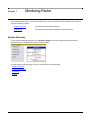
System Summary ............................................................................................................................................. 89
Ethernet Interface Information.................................................................................................................... 90
Remote Connection Information ................................................................................................................ 90
IP Routing Information ............................................................................................................................... 91
System Information .................................................................................................................................... 91
Diagnostics ....................................................................................................................................................... 92
PPPoE Session.......................................................................................................................................... 92
Interface Information .................................................................................................................................. 93
ATM Statistics ............................................................................................................................................ 93
Routing Table Information.......................................................................................................................... 94
Files Information......................................................................................................................................... 94
Memory Usage........................................................................................................................................... 95
List All Configuration Data.......................................................................................................................... 95
TCP/IP Statistics ........................................................................................................................................ 96
SIEMENS
iii
Chapter 1
Product Specifications
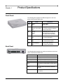
Front Panel
The following table explains the LEDs that appear on the front
panel of the Siemens 5890 router.
Light
Color
Indications
Power
Green
Off
Power is ON
Power is OFF
Test
Yellow:
Green: (2 sec blink)
Off:
Running Power On Self Test
Self Test successful (heartbeat)
Router is shut down
Link
Yellow:
Green:
Off:
Establishing DSL modem link
DSL modem link successful
DSL modem link is shut down
WAN
Green flashing:
Off:
WAN traffic detected
No current WAN traffic
LANT
Green flashing:
Off:
Transmit traffic detected
No current transmit traffic
LANR
Green flashing:
Off:
Receive traffic detected
No current receive traffic
Back Panel
The following table describes the various connections on the back
panel of the Siemens 5890 router.
Connection
SIEMENS
Function
Power
Turns power on and off.
12VDC 1A MAX
12Vdc, 1Amax input.
Ethernet Ports
5-port Ethernet Switch: RJ-45 (5).
Port 5
Ethernet port configurable as either DMZ or
LAN.
MGMT
Use only when instructed by Technical
Support.
WAN Port
IDSL/SDSL/SHDSL RJ-45. Uses Pair 1
(pins 4 & 5).
1
Chapter 1 Product Specifications
Hardware Specifications
SIEMENS 5890 DSL Router
User’s Guide
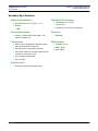
Hardware Specifications
Physical Specifications
• Dimensions:8.25" W x 7.0" D x 1.7" H
• Weight:
– TBD
Power Requirements
• US/NA = 120VAC 60Hz 20W, ROW = 100-
Operational Environment
• Temperature:0°F to 104°F
• 10°C to 40°C
• Humidity: 8% to 95% non-condensing
Processor
• MPC859T
240VAC 50-60Hz 1A
LAN Interface
• Built-in 5-port 10/100 Base-T Ethernet switch
with link status LED for each port
• Auto detect full or half duplex operation
• Auto detect regular or crossover cable for easy
WAN Interface
• G.SHDSL, 2-wire
• SDSL, 2B1Q
• IDSL, 2B1Q
connection to a switch or hub
• Ports configured individually
• Port mirroring
Serial Interface
• One asynchronous serial console port
SIEMENS
2
Chapter 1 Product Specifications
Software Specifications
SIEMENS 5890 DSL Router
User’s Guide
Software Specifications
Configuration Management
• Easy Setup Web Management Interface
• Configuration and management using HTTP,
serial console, SNMP, SSH, or Telnet
• TFTP download/upload of new software and
configuration files
• Dynamic event and history logging
• Network boot uses the BootP server (RFC
2131, RFC 2132)
• Syslog Server Support
• Performance monitoring data available via
SNMP
Differentiated Services - Quality of
Service provisioning
• Weighted Fair Queuing (WFQ)
• Differentiated Services (DiffServ)
• Traffic Shaping
Dial Backup
•
•
•
•
•
SIEMENS
Failover to external V.90 via console port
Web Management Interface
User selectable fail/restore criteria
Routing
• TCP/IP with RIP1 (RFC 1058), RIP1 compatible
and RIP2 (RFC 1389) or static routing on the
LAN or WAN
• Novell® IPX with RIP/SAP (RFC 1552)
• DHCP client (RFC 2132)
• DHCP server - Automatic assignment of IP
address, mask, default gateway and DNS
server addresses to workstations (RFC 2131,
2132)
• DHCP relay agent (RFC 1542)
• DNS relay
• Multiple subnets on LAN support NAT, RIP1,
RIP2, ARP, and IP filters
• Virtual routing
IP Address Translation
• Network renumbering (RFC 1631)
• Network Address Translation (NAT/PAT)
• NAT passthrough support for numerous
applications including IPSec, PPTP, H.323, SIP
and NetMeeting
• Supports public Web and e-mail servers with
NAT
Optional modem connector (DB9 or DB25)
Supports L2TP and IPSec tunnel failover
3
Chapter 1 Product Specifications
Software Specifications
SIEMENS 5890 DSL Router
User’s Guide
ATM
Frame Relay
• Encapsulation (IP, Bridging, and Bridge
• Support of frame relay ANSI T1.618 and CCIT
Encapsulated Routing) (RFC 2684/1483)
• PPP over ATM (LLC and VC multiplexing) (RFC
2364)
•
•
•
•
Classical IP over ATM (RFC 2225)
Classical IP (RFC 1577)
AAL5
Virtual Circuit (VC) traffi c shaping (CBR, PCR,
UBR, VBR)
Q.922 formats
•
•
•
•
•
•
DLCI support
Inverse ARP support
LMI support including LMI protocol discovery
LLCP auto-update
CIR & EIR rate enforcement
Network Congestion Management
• No pre-defi ned limit on VCs
• I.610 OAM F5 end-to-end and segment
LoopBack
• Initiates and responds to LoopBack signaling
PPP (RFC 1661, RFC 2364)
• Data compression of up to 4:1 (STAC™ LZS)
(RFC 1974)
• Van Jacobsen header compression (RFC 1144)
• Spoofing and filtering (IP-RIP, IPX-RIP, SAP,
Watchdog, serialization)
•
•
•
•
•
•
•
•
Automatic IP and DNS assignment (RFC 1877)
PPP over Ethernet (RFC 2516)
PPP over ATM (RFC 2364)
Security
• Role-based management
• User authentication (PAP/CHAP) with PPP
(RFC 1334, RFC 1994)
• Password control for Configuration Manager
• SNMP community name reassignment
• HTTP/Syslog/SNMP/Telnet port reassignment,
access control list
• Secure VPN support (L2TP, IPSec, IKE, DES,
Bridging (RFC 1638)
3DES)
IP Routing (RFC 1331)
– No pre-defined limit on VPN tunnels
IPX Routing (RFC 1552)
Multiclass extensions to MLPPP (RFC 2686)
MLPPP (RFC 1990)
– IPSec tunnel and transport modes with AH
and ESP
– Implements RFCs 1321, 1828, 1829, 2085,
2104, 2401-2410, 2412, 2420, 2437, 2451,
and 2631 (Groups 1 and 2)
• Firewall (IP filtering)
• Stateful Firewall (ICSA Compliant)
• Secure Management Communications
– IPsec
– SSH
• Radius Server support
SIEMENS
4
Chapter 2
Installation
This chapter describes the steps you must take to install and configure the various components in your
network to utilize the Siemens DSL broadband internet router. This includes setting up the hardware
connections to the Internet router, configuring the PC to use the Internet router for Internet access, and setting
up the Internet router configuration. Before beginning installation, make sure you meet all installation
requirements.
Installation Requirements
Before beginning the installation and configuration of the various components on the network, make sure you
received all the package contents, meet the basic PC requirements, and have the necessary information from
your network Service Provider.
Package Contents
Your package should contain the items listed below. If you determine anything to be damaged or missing,
please contact the dealer from whom the equipment was purchased.
•
•
•
•
•
•
One Siemens 5890 router
One Siemens Documentation CD-ROM
One AC power cord
One RJ-45 Ethernet cable, red label
One RJ-45 Ethernet cable, yellow label
One RJ-45 to DB-9 serial port adapter (console)
PC Requirements
At a minimum, your computer must be equipped with the following to successfully install the broadband
Internet router.
•
•
•
•
•
CD-ROM Drive
Ethernet network interface card
TCP/IP network protocol installed on your PC
Web browser
Terminal emulation software, if you want to configure your router via your computer’s serial port before
placing it into service on a network.
SIEMENS
5
SIEMENS 5890 DSL Router
User’s Guide
Chapter 2 Installation
Installation Requirements
Network Service Provider Requirements
Your Network Service Provider will provide you with information to configure your router’s WAN connection.
Depending upon the type of service that you ordered, you will need some of the items from the following list.
Contact your Network Service Provider for specific details on the items you should receive.
• DNS address
• One or more IP addresses and a subnet mask
SIEMENS
6
Chapter 2 Installation
Hardware Installation
SIEMENS 5890 DSL Router
User’s Guide
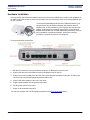
Hardware Installation
You may position the Siemens broadband router at any convenient location where it will be well ventilated. Do
not stack it with other devices or place it on the carpet. You can connect the router to an existing Ethernet port
on your computer.
To connect the SpeedStream device via the Ethernet interface, your
computer must have an Ethernet adapter (also called a network
interface card, or NIC) installed. If your computer does not have this
adapter, install it before proceeding further. Refer to your Ethernet
adapter documentation for complete installation instructions. Once you
verify installation of an Ethernet adapter, perform the following
procedure to connect the router to your computer.
To set up the harware connections:
1. With the PC powered off, connect the Ethernet cable to an Ethernet port on the router.
2. Connect the other end of the Ethernet cable to the Ethernet port on the PC.
3. Connect your router’s WAN port to the DSL phone jack using the remaining RJ-45 cable. To reduce the
risk of fire, use only 26 AWG gauge telecommunication cord.
4. Connect the power adapter to the rear of the router.
5. Plug the power adapter into the electrical wall outlet.
6. Flip the power switch on the router.
7. Power on all connected computers.
You can now configure the TCP/IP settings as detailed in the PC Configuration section.
SIEMENS
7
Chapter 2 Installation
PC Configuration
SIEMENS 5890 DSL Router
User’s Guide
PC Configuration
Your PC must be configured to use the TCP/IP protocol suite over the Internet, and to accept Dynamic Host
Configuration Protocol address assignments from the router. Although this is the default settings for the PC, it
is a good idea to verify that they have not been changed.
Each supported PC Operating System varies slightly in how the configuration windows are presented. Select
the Operating System installed on the PC connected to the router from the list below and follow the associated
procedure.
• Windows 98/ME
• Windows NT 4
• Windows 2000
• Windows XP
• Mac OS 9.x
• Mac OS X
• Linux OS
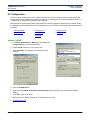
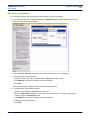
Windows 98/ME
1. Click Start >Control Panel > Network. This displays the
Configuration tab on the Network window.
2. Select TCP/IP protocol for your network card.
3. Click Properties. This displays the TCP/IP Properties
window.
4. Click the IP Address tab.
5. Ensure that the Obtain an IP address automatically option is selected. This is the default Windows
setting.
6. Click OK to close each dialog.
7. Restart the PC to ensure it obtains an IP address from the router.
8. Configure the router.
SIEMENS
8
SIEMENS 5890 DSL Router
User’s Guide
Chapter 2 Installation
PC Configuration
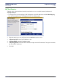
Windows NT 4
1. On your desktop, right click on the Network Neighborhood
icon. This displays the Network window.
2. Click the Protocols tab.
3.
Select TCP/IP Protocol from the Network Protocols list.
4.
Click Properties. This displays the Microsoft TCP/IP
Properties window.
5. Click the IP Address tab.
6. On the IP Address tab, select Obtain an IP address from a DHCP server.
7. Click OK to close each dialog.
8. Restart the PC to ensure it obtains an IP address from the router.
9. Configure the router.
SIEMENS
9
SIEMENS 5890 DSL Router
User’s Guide
Chapter 2 Installation
PC Configuration
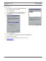
Windows 2000
1. Select Start >Settings >Control Panel. This displays the Control Panel window.
2. Double-click the Network and Dial-up Connection icon. This
displays the Network and Dialup Connection window.
3. Right-click Local Area Connections and select Properties.
This displays the Local Area Connections Properties window.
4. Select Internet Protocol (TCP/IP) from the list of components.
5.
Click Properties. This displays the Internet Protocol (TCP/IP)
Properties window.
6. Ensure that the Obtain an IP address automatically and Obtain DNS server address automatically
options are selected.
7. Click OK to close each dialog.
8. Restart the PC to ensure it obtains an IP address from the router.
9. Configure the router.
SIEMENS
10
SIEMENS 5890 DSL Router
User’s Guide
Chapter 2 Installation
PC Configuration
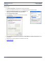
Windows XP
1. Click Start >Control Panel. This displays the Control Panel window.
2. Double-click the Network Connections icon. This displays the Network Connection window.
3. Right-click Local Area Connection, then click Properties. This
displays the Local Area Connection Properties window.
4. Select Internet Protocol TCP/IP.
5. Click Properties. This displays the Internet Protocol (TCP/IP)
Properties window.
6. Ensure the Obtain an IP address automatically and Obtain DNS server address automatically options
are selected.
7. Restart the PC to ensure it obtains an IP address from the router.
8. Configure the router.
SIEMENS
11
SIEMENS 5890 DSL Router
User’s Guide
Chapter 2 Installation
PC Configuration
Mac OS 9.x
1. Click Apple -> Control Panels -> TCP/IP. This displays the TCP/IP Control Panel window.
2. Select Ethernet from the Connect via drop-down menu.
3. Select Using DHCP Server from the Configure drop-down menu.
4. Complete the fields shown with any information supplied by your service provider.
5. Close window and save changes.
6. Configure the router.
SIEMENS
12
SIEMENS 5890 DSL Router
User’s Guide
Chapter 2 Installation
PC Configuration
Mac OSX
1. Click Apple -> System Preferences. This displays the System Preferences window.
2. Double-click the Network icon under the Internet & Network section. This displays the Network window.
3. Select Ethernet from the Connect via drop-down menu.
4. Select Using DHCP Server from the Configure drop-down menu.
5. Enter any information supplied by your service provider.
6. Click Apply Now to save and exit the Network window.
7. Configure the router.
SIEMENS
13
SIEMENS 5890 DSL Router
User’s Guide
Chapter 2 Installation
PC Configuration
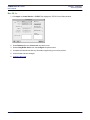
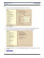
Linux
1. From a terminal window, run linuxconfig. This displays the Config window.
2. Click the Adaptor tab.
3. Enter any information specified by your service provider in the fields under the appropriate Adapter tab.
4. When settings are completed, click Accept. This displays the Status of the system tab.
5. To update the system status, ensure that the Activate the changes button is highlighted, then click Act/
Changes.
6. Configure the router.
SIEMENS
14
SIEMENS 5890 DSL Router
User’s Guide
Chapter 2 Installation
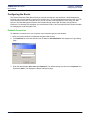
Configuring the Router
Configuring the Router
The Siemens Business Class Router family of products provides two user interfaces: a Web Management
Interface and a console-based Command Line Interface (CLI). The Web Management Interface uses an HTTP
server housed in the router. Using this server, you can connect to and manage the router using your Web
browser. The Web Management Interface is accessible through most HTML browsers, though Internet
Explorer 4.0 or Netscape 4.0 and higher are recommended. Refer to the Technical Reference Guide for details
on managing the router through the CLI.
Establish Connection
To establish a connection from your computer to the router through your Web browser:
1. Open your Internet Explorer or Netscape Navigator Web browser.
2. In the Address bar, enter the default router IP address: 192.168.254.254. This displays the Login Dialog
page.
3. Enter the administrative User name and Password. The default settings are User name: superuser and
Password: admin. This displays the Router Information page.
SIEMENS
15
Chapter 2 Installation
Configuring the Router
SIEMENS 5890 DSL Router
User’s Guide
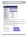
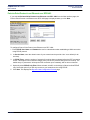
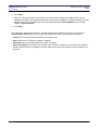
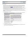
Router Information Page
The Router Information Page is the first page you encounter after logging into the router.
The Router Information page displays basic router information and configuration settings. On the Router
Information page, the following information is presented:
• Router Information: Including the model number, software version number, and hardware description.
• Router Configuration: Displays router configuration details such as LAN IP address, WAN Data Link
Connection Identifier DLCI, WAN protocol and WAN network settings.
In the left navigation pane of this page, there are configuration, diagnostic, and status and statistic options for
the router. In this document, these features are grouped according to User Access Control, Advanced Router
Functions, Security, and Monitoring Health and Status.
Use the table below to locate detailed instructions for the desired function.
To do this:
Refer to:
Perform Easy Setup
Chapter titled "Easy Setup"
Configure users on the router.
Chapter titled "User Setup"
Configure advanced features.
Chapter titled "Advanced Setup"
Configure security features.
Chapter titled "Security Setup"
Monitor the health of the router.
Chapter titled "Monitoring Router"
Manage router using Command Line Interface
Command Line Interface Guide
SIEMENS
16
Chapter 3
Easy Setup
This chapter describes how to define router configuration settings using the Easy Setup Wizard. These
settings control access to the Wide Area Network (WAN) and Local Area Network (LAN). During the Easy
Setup procedure, you will be prompted to specify configuration parameters that may require information from
your service provider.
Access Easy Setup Wizard
To access the Easy Setup Wizard, click Easy Setup in the left navigation pane of the Router Information
window. This wizard will walk you through the configuration screens necessary to setup the router. You can
exit the Easy Setup Wizard at anytime by clicking Cancel on the bottom of the configuration page. If the wizard
is cancelled, no changes will be made and you will need to begin again.
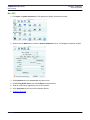
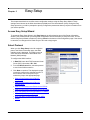
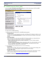
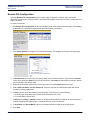
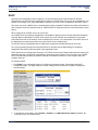
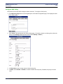
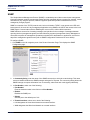
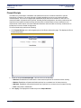
Select Protocol
When you click Easy Setup in the left navigation
pane of the Router Information page, the WAN
Interface page is displayed. This page is used to
enter and review information about Wide Area
Network (WAN) settings.
To configure the WAN interface:
1. In Data PVC, enter the ATM Permanent Virtual
Circuit (PVC) information: VPI / VCI.
2. From the Wan Protocol list, select the protocol
to use for the WAN connection.
3. Click Next to continue. This displays the page
required to configure the selected protocol. In
the list below, click on the protocol you
selected to jump to the appropriate page.
• Point-to-Point Protocol over ATM (VC
Multiplexing)
• Point-to-Point Protocol over ATM (LLC
Encapsulation)
•
•
•
•
•
•
SIEMENS
Point-to-Point Protocol over Ethernet over PPPoA
Point-to-Point Protocol over Ethernet over RFC1483
RFC 1483 (Multiprotocol Encapsulation LLC/SNAP)
RFC 1483 (VC Multiplexing Routed)
RFC 1483 MAC Encapsulated Routing (MER)
RAWIP
17
SIEMENS 5890 DSL Router
User’s Guide
Chapter 3 Easy Setup
Select Protocol
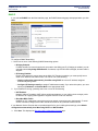
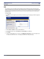
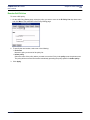
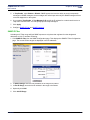
Point-to-Point Protocol over ATM (VC Multiplexing)
If you selected Point-to-Point Protocol over ATM (VC Multiplexing) from the Wan Interface page, the Pointto-Point Protocol page is displayed when you click Next.
To configure Point-to-Point Protocol:
1. Enter PPP User Name and Password to use for authentication when establishing a WAN connection using
PPP protocol.
2. Select one or more of the following PPP Networking options:
• Bridging Enabled:
Forward all traffic for remote hosts that is not routed to the WAN (non-IP). If bridging is enabled, you can
optionally select Only bridge PPPoE traffic. If selected, only PPPoE traffic is bridged; all other traffic is
stopped.
3. IP Routing Enabled:
Route all IP traffic to remote hosts.
4. If you enabled IP routing, select one of the following methods for configuring IP routing:
• Obtain configuration automatically from WAN
IP routing parameters are obtained from the WAN.
• Configure IP Routing manually
IP routing parameters are set manually. If you select this options, you must provide the Source WAN IP
Address, Subnet Mask, and Default Gateway.
SIEMENS
18
SIEMENS 5890 DSL Router
User’s Guide
Chapter 3 Easy Setup
Select Protocol
5. If you enabled IP routing, optionally select one or more of the following:
• NAT Enabled:
Network Address Translation (NAT) allows multiple workstations on your LAN to share a single, public
IP address. All outgoing traffic appears to originate from the router’s IP address.
• Block Net BIOS Traffic:
NetBIOS is a PC networking protocol that can keep network connections open inadvertently. To avoid
excess connection charges, such traffic should be blocked on any metered network service.
6. Click Next. This displays the Dynamic Host Configuration Protocol page.
SIEMENS
19
SIEMENS 5890 DSL Router
User’s Guide
Chapter 3 Easy Setup
Select Protocol
Point-to-Point Protocol over ATM (LLC Encapsulation)
If you selected Point-to-Point Protocol over ATM (LLC Encapsulation) from the Wan Interface page, the
Point-to-Point Protocol page is displayed when you click Next.
To configure Point-to-Point Protocol:
1. Enter PPP User Name and Password to use for authentication when establishing a WAN connection using
PPP protocol.
2. Select one or more of the following PPP Networking options:
• Bridging Enabled:
Forward all traffic for remote hosts that is not routed to the WAN (non-IP). If bridging is enabled, you can
optionally select Only bridge PPPoE traffic. If selected, only PPPoE traffic is bridged; all other traffic is
stopped.
3. IP Routing Enabled:
Route all IP traffic to remote hosts.
4. If you enabled IP routing, select one of the following methods for configuring IP routing:
• Obtain configuration automatically from WAN
IP routing parameters are obtained from the WAN.
• Configure IP Routing manually
IP routing parameters are set manually. If you select this options, you must the Source WAN IP
Address, Subnet Mask, and Default Gateway.
SIEMENS
20
SIEMENS 5890 DSL Router
User’s Guide
Chapter 3 Easy Setup
Select Protocol
5. If you enabled IP routing, optionally select one or more of the following:
• NAT Enabled:
Network Address Translation (NAT) allows multiple workstations on your LAN to share a single, public
IP address. All outgoing traffic appears to originate from the router’s IP address.
• Block Net BIOS Traffic:
NetBIOS is a PC networking protocol that can keep network connections open inadvertently. To avoid
excess connection charges, such traffic should be blocked on any metered network service.
6. Click Next. This displays the Dynamic Host Configuration Protocol page.
SIEMENS
21
SIEMENS 5890 DSL Router
User’s Guide
Chapter 3 Easy Setup
Select Protocol
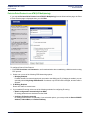
RFC 1483 (Multiprotocol Encapsulation LLC/SNAP)
If you selected RFC 1483 (Multiprotocol Encapsulation LLC/SNAP) from the Wan Interface page, the RFC
1483 Networking page is displayed when you click Next.
To configure RFC 1483:
1. Select one or more of the following RFC 1483 networking options:
• Bridging Enabled:
Forward all traffic for remote hosts that is not routed to the WAN (non-IP). If bridging is enabled, you can
optionally select Only bridge PPPoE traffic. If selected, only PPPoE traffic is bridged; all other traffic is
stopped.
• IP Routing Enabled:
Routes all IP packets for remote hosts to the WAN. If IP Routing is enabled, you must specify how to
obtain an IP address and subnet mask. This can be one of the following:
– Obtain configuration automatically from Wan using DHCP to have an IP address assigned
automatically using DHCP.
– Configure IP Routing manually to assign IP addresses manually. If you select this option, you must
specify an IP Address and Subnet Mask in the appropriate fields.
2. If you enabled IP routing, optionally select one or more of the following:
• NAT Enabled:
Network Address Translation (NAT) allows multiple workstations on your LAN to share a single, public
IP address. All outgoing traffic appears to originate from the router’s IP address.
• Block Net BIOS Traffic:
NetBIOS is a PC networking protocol that can keep network connections open inadvertently. To avoid
excess connection charges, such traffic should be blocked on any metered network service.
3. Click Next. This displays the Dynamic Host Configuration Protocol page.
SIEMENS
22
SIEMENS 5890 DSL Router
User’s Guide
Chapter 3 Easy Setup
Select Protocol
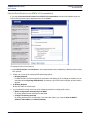
RFC 1483 (VC Multiplexing Routed)
If you selected RFC 1483 (VC Multiplexing Routed) from the Wan Interface page, the RFC 1483 Networking
page is displayed when you click Next.
To configure RFC 1483:
1. Select one or more of the following RFC 1483 networking options:
• Bridging Enabled:
Forward all traffic for remote hosts that is not routed to the WAN (non-IP). If bridging is enabled, you can
optionally select Only bridge PPPoE traffic. If selected, only PPPoE traffic is bridged; all other traffic is
stopped.
• IP Routing Enabled:
Routes all IP packets for remote hosts to the WAN. If IP Routing is enabled, you must specify how to
obtain an IP address and subnet mask. This can be one of the following:
– Obtain configuration automatically from Wan using DHCP to have an IP address assigned
automatically using DHCP.
– Configure IP Routing manually to assign IP addresses manually. If you select this option, you must
specify an IP Address and Subnet Mask in the appropriate fields.
2. If you enabled IP routing, optionally select one or more of the following:
• NAT Enabled:
Network Address Translation (NAT) allows multiple workstations on your LAN to share a single, public
IP address. All outgoing traffic appears to originate from the router’s IP address.
• Block Net BIOS Traffic:
NetBIOS is a PC networking protocol that can keep network connections open inadvertently. To avoid
excess connection charges, such traffic should be blocked on any metered network service.
3. Click Next. This displays the Dynamic Host Configuration Protocol page.
SIEMENS
23
SIEMENS 5890 DSL Router
User’s Guide
Chapter 3 Easy Setup
Select Protocol
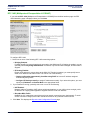
Point-to-Point Protocol over Ethernet over RFC1483
If you selected Point-to-Point Protocol over Ethernet over RFC 1483 from the Wan Interface page, the
Point-to-Point Protocol over Ethernet over RFC 1483 page is displayed when you click Next.
To configure Point-to-Point Protocol over Ethernet over RFC 1483:
1. Enter PPPoE User Name and Password to use for authentication when establishing a WAN connection
using PPPoE protocol.
2. In Service Name, enter the domain name of your network service provider. Use * as a default (for all
services).
3. In PPPoE Timer, enter the number of seconds of inactivity that must elapse before the PPP connection
closes. This helps to limit connection charges from your service provider during times of inactivity. The
default entry of “permanent” will keep the PPP connection open constantly, with no time out interval.
4. Optionally select PPPoE only Filter. When selected, all traffic on the bridge is filtered to allow PPPoE
only. Select this option if you will only connect to your network service using PPPoE.
5. Click Next. This displays the Dynamic Host Configuration Protocol page.
SIEMENS
24
SIEMENS 5890 DSL Router
User’s Guide
Chapter 3 Easy Setup
Select Protocol
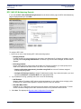
RFC 1483 MAC Encapsulated Routing (MER)
If you selected RFC 1483 MAC Encapsulated Routing from the Wan Interface page, the RFC 1483 MER
Networking page is displayed when you click Next.
To configure RFC 1483 MER Networking:
1. Select one or more of the following RFC 1483 MER Networking options:
• Bridging Enabled:
Forward all traffic for remote hosts that is not routed to the WAN (non-IP). If bridging is enabled, you can
optionally select Only bridge PPPoE traffic. If selected, only PPPoE traffic is bridged; all other traffic is
stopped.
• IP Routing Enabled:
Routes all IP packets for remote hosts to the WAN. If IP Routing is enabled, you must specify how to
obtain an IP address and subnet mask. This can be one of the following:
– Obtain configuration automatically from Wan using DHCP to have an IP address assigned
automatically using DHCP.
– Configure IP Routing manually to assign IP addresses manually. If you select this option, you must
specify an IP Address, Subnet Mask, and Default Gateway in the appropriate fields. Default
Gateway assigns the IP address of the next-hop route.
2. If you enabled IP routing, optionally select one or more of the following:
• NAT Enabled:
Network Address Translation (NAT) allows multiple workstations on your LAN to share a single, public
IP address. All outgoing traffic appears to originate from the router’s IP address.
• Block Net BIOS Traffic:
NetBIOS is a PC networking protocol that can keep network connections open inadvertently. To avoid
excess connection charges, such traffic should be blocked on any metered network service.
3. Click Next. This displays the Dynamic Host Configuration Protocol page.
SIEMENS
25
SIEMENS 5890 DSL Router
User’s Guide
Chapter 3 Easy Setup
Select Protocol
RAW IP
If you selected RAWIP from the Wan Interface page, the RAWIP Networking page is displayed when you click
Next.
To configure RAWIP Networking:
1. Select one or more of the following RAWIP Networking options:
• Bridging Enabled:
Forward all traffic for remote hosts that is not routed to the WAN (non-IP). If bridging is enabled, you can
optionally select Only bridge PPPoE traffic. If selected, only PPPoE traffic is bridged; all other traffic is
stopped
• IP Routing Enabled:
Routes all IP packets for remote hosts to the WAN. If IP Routing is enabled, you must specify how to
obtain an IP address and subnet mask. This can be one of the following:
– Obtain configuration automatically from Wan using DHCP to have an IP address assigned
automatically using DHCP.
– Configure IP Routing manually to assign IP addresses manually. If you select this option, you must
specify an IP Address and Subnet Mask in the appropriate fields.
2. If you enabled IP routing, optionally select one or more of the following:
• NAT Enabled:
Network Address Translation (NAT) allows multiple workstations on your LAN to share a single, public
IP address. All outgoing traffic appears to originate from the router’s IP address.
• Block Net BIOS Traffic:
NetBIOS is a PC networking protocol that can keep network connections open inadvertently. To avoid
excess connection charges, such traffic should be blocked on any metered network service.
If your Network Service Provider has not provided specifics for use in making these settings, select Obtain
configuration automatically from Wan using DHCP and NAT Enabled.
3. Click Next. This displays the Dynamic Host Configuration Protocol page.
SIEMENS
26
SIEMENS 5890 DSL Router
User’s Guide
Chapter 3 Easy Setup
Select Protocol
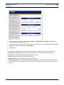
Dynamic Host Configuration Protocol
Dynamic Host Configuration Protocol (DHCP) provides a dynamic, “upon request,” IP address to computers
and other networked devices. The router can act as a DHCP server for devices on your local network.
The router provides the flexibility to use different ranges of IP addresses to be assigned by the DHCP server
housed in the router. DHCP configuration is done from the DHCP Configuration page.
To configure DHCP:
1. Optionally select DHCP server enabled on the LAN. If selected, the DHCP server dynamically assigns IP
addresses to all LAN-side devices.
2. Select one of the following to configure the Domain Name Service:
• Obtain DNS information automatically:
The DNS server address will be learned when DHCP client requests are placed over the WAN link.
• Configure DNS manually:
Define DNS server address manually from information you get from your service provider. If you select
this option, provide the following information.
– Domain Name
The router’s DNS domain name as assigned by your service provider.
– Primary DNS Server
IP address where DNS requests will be sent.
– Secondary DNS Server
Optional. IP address where DNS requests will be sent if the primary DNS server is unavailable.
– Primary WINS Server
IP address of the Windows Internet Naming Service where WINS requests will be sent. This maps
NetBIOS names to IP addresses similar to DNS.
– Secondary WINS Server
Optional. IP address where WINS requests will be sent if the primary WINS server is unavailable.
3. Click Next. This displays the LAN IP Configuration page.
SIEMENS
27
SIEMENS 5890 DSL Router
User’s Guide
Chapter 3 Easy Setup
Select Protocol
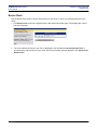
Local Area Network Configuration
Local Area Network configuration information is configured on the LAN IP Configuration page.
To configure the Local Area Network:
1. In IP Address, enter the network address of the router. This address must be globally unique unless NAT
has been enabled.
2. In Subnet Mask, enter the subnet mask to use along with the IP address to determine if specific LAN IP
traffic should be forwarded to the WAN.
3. Click Save and Reboot. The router will reboot with the new configuration settings.
On completion of the reboot process, you will be required to login again.
SIEMENS
28
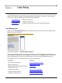
User Setup
Chapter 4
This chapter describes how to set up users on the router and control their access to router functions and to the
Internet. The features that control users and their access are listed below. To access one of these options,
click the link on the left navigation pane of the Router Information page.
User Management
Manage user accounts.
Change Password
Change user password.
Access Control
Configure remote access to the router configuration settings.
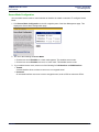
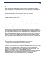
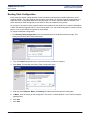
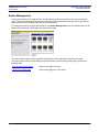
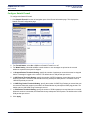
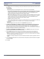
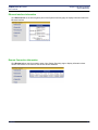
User Management
When you select User Management from the left navigation pane of the Router Information page, the User
Management page is displayed.
Use this page to add, delete, edit, and view user accounts. You can also use this page to configure secure
mode, configure the Radius Server, and configure the Tacplus Server. Click Home at anytime to return to the
Router Information page. To access one of these options, click its link on the User Management page.
Use the table below to locate detailed instructions for the desired function.
To do this:
Refer to:
Add or modify a user account
Add or Modify A User Account
Delete a user account
Delete a User Account
Specify database for identifying users when
logging into the router.
User Lookup
Configure Secure Mode
Secure Mode Configuration
Configure the Radius Server
Configure the Radius Server
Configure the Tacplus Server
Configure the Tacplus Server
SIEMENS
29
SIEMENS 5890 DSL Router
User’s Guide
Chapter 4 User Setup
User Management
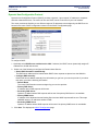
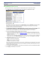
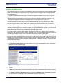
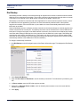
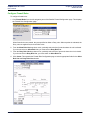
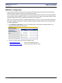
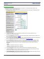
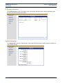
Adding/Modifying A User Account
User accounts are used to control access to the router and the Internet. To add a user account:
1. Click New User on the User Management page. This displays the Add/Modify User page.
(To modify a user, select the desired name in the Select User list and click Edit User to display the Add/
Modify User page. Note that changing the password or privileges of an existing user account may
terminate a user’s current activity or connection.)
2. Enter User Name, Password, and Confirm Password in the appropriate boxes. (The User Name cannot
be modified for an existing account. When editing an existing account, the Password and Confirm
Password values are not displayed. If you leave them blank, the password is not changed.)
3. Do one of the following to assign privileges to this user account:
• Select one of the buttons at the top of this page to automatically assign pre-set privileges to the user
based on common user roles. (Refer to Management Classes for details on the privileges automatically
assigned to each role.)
• Manually select the management activity you want to assign to this user account. For each management
activity class, click to select Read, Read-Write privileges for the user, or select None for no privilege.
4. In Allow Access From, specify one or more of the following:
• LAN: Can access from the LAN side.
• WAN: Can access from the WAN side.
• Console: Can access from a console.
User access verification is performed if the user account is verified during user authentication. User access
verifies that the user account can access the router through the connectivity method being used, such as
over the LAN or through a console.
5. Click Enabled for Account Access to enable this account. By default, accounts are disabled when added.
6. Click Apply to add/modify the user account.
SIEMENS
30
SIEMENS 5890 DSL Router
User’s Guide
Chapter 4 User Setup
User Management
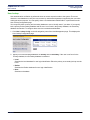
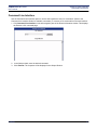
Deleting A User Account
To delete a user account:
1. Select the name of the account you want to delete in the Select User list on the User Management page,
then click Delete User.
2. When prompted, click OK to confirm the account deletion.
SIEMENS
31
SIEMENS 5890 DSL Router
User’s Guide
Chapter 4 User Setup
User Management
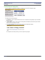
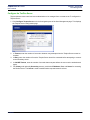
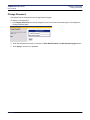
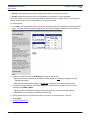
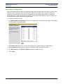
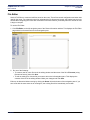
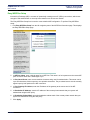
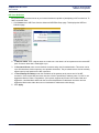
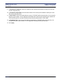
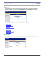
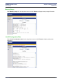
User Lookup
User authentication verification is performed when an access request is made to the system. The router
checks the user database to verify the user account by username and password, supplied by the user when
making the access request. You can specify where user authentication/identification is performed from the
User Lookup Configuration page.
You can specify both a primary and secondary database to use to identify users if you desire. If you specify
both a primary and secondary database and the user is not found in the primary database, the secondary
database is searched. To configure where user's are authenticated/identified:
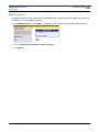
1. Click User Lookup Config on the left navigation pane of the User Management page. This displays the
User Lookup Configuration page.
2. Specify one of the following databases for Primary and for Secondary. If the user is not found in the
Primary database, the Secondary database is searched.
• Local
Searches the local database for user login identification. Either the primary or secondary lookup must be
Local.
• Radius
Searches the Radius database for user login identification.
• None
Searches no database.
SIEMENS
32
SIEMENS 5890 DSL Router
User’s Guide
Chapter 4 User Setup
User Management
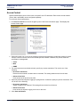
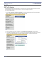
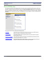
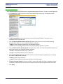
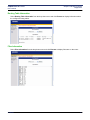
Secure Mode Configuration
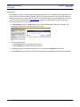
You can enable secure mode to control whether an interface is trusted or untrusted. To configure Secure
Mode:
1. Click Secure Mode Configuration on the left navigation pane of the User Management page. This
displays the Secure Mode Configuration page.
2. Do one of the following for Secure Mode:
• Click the box next to Enabled so a check mark appears. This enables secure mode.
• Click the box next to Enabled so there is no check mark. This disables secure mode.
3. If you enabled secure mode, select one of the following for LAN Interface and WAN Interface:
• Trusted:
A trusted interface does not have to come over an encrypted tunnel.
• Untrusted:
An untrusted interface must come over an encrypted tunnel, such as SSH or telnet-over-IPSec.
SIEMENS
33
SIEMENS 5890 DSL Router
User’s Guide
Chapter 4 User Setup
User Management
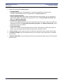
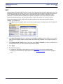
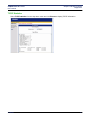
Configure the Radius Server
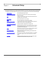
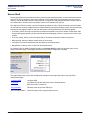
Remote Authentication Dial In User Service (RADIUS) is client-server based access control and authentication
feature. The RADIUS client resides locally on the router and works in conjunction with a variety of RADIUS
Server applications.
• The client is responsible for passing user information to designated RADIUS servers, then acting on the
returned response.
• RADIUS servers are responsible for receiving user connection requests, authenticating the user, then
returning all configuration information necessary for the client to deliver service to the user.
Transactions between the client and server are authenticated through the use of a shared secret, which is
never sent over the network. In addition, any user passwords are sent encrypted between the client and
RADIUS server to further secure account passwords.
When the router is configured to use RADIUS, a user attempting to login presents authentication information
(Username and Password) to the router. Upon receipt, the router’s RADIUS Client creates an “access-request”
containing username, the user's password, and method being used to access the system. The password is
hidden using a method based on the RSA Message Digest Algorithm MD5 [3].
The access request is submitted to the RADIUS server via the network. If no response is returned within a
length of time, the request is re-sent a specified number of times. The router’s RADIUS client can also forward
requests to a secondary server in the event that the primary server is down or unreachable.
Once the RADIUS server receives the request, it validates the RADIUS client that sent the request. A request
from a client for which the RADIUS server does not have a shared secret is discarded. If the client is valid, the
RADIUS server consults a database of users to find the user whose name matches the request. The user entry
in the database contains the required elements for authentication including the username, password, access
and management privileges.
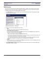
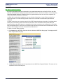
To configure the RADIUS Server:
1. Click Configure Radius Server on the left navigation pane of the User Management page. This displays
the Radius Server Configuration page.
2. In Timeout, enter the number of seconds to between retry attempts when the Radius Server cannot be
reached.
3. In Retry, enter the number of times the Radius Server should be contacted before attempting to connect to
the secondary server.
4. For Primary and optionally Secondary servers, provide the IP Address, Port, and Secret for accessing
the Radius Server. The Secret is used to authenticate requests between servers.
SIEMENS
34
SIEMENS 5890 DSL Router
User’s Guide
Chapter 4 User Setup
User Management
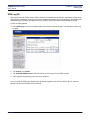
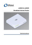
Configure the TacPlus Server
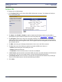
Tacplus allows access control and user authentication to be managed from a remote server.To configure the
Tacplus Server:
1. Click Configure Tacplus Server on the left navigation pane of the User Management page. This displays
the Tacplus Server Configuration page.
2. In Timeout, enter the number of seconds to between retry attempts when the Tacplus Server cannot be
reached.
3. In Retry, enter the number of times the Tacplus Server should be contacted before attempting to connect
to the secondary server.
4. In CACHE Timeout, enter the number of seconds that must pass before the user must be authenticated
again.
5. For Primary and optionally Secondary servers, provide the IP Address, Port, and Secret for accessing
the Radius Server. The Secret is used to authentication requests between servers.
SIEMENS
35
Chapter 4 User Setup
User Management
SIEMENS 5890 DSL Router
User’s Guide
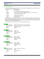
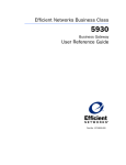
Management Classes
All system operations, are partitioned into functional groups called management classes. Management classes
group functions into the following categories.
Class
Functional Areas
Voice
Network
System
Security
Admin
Debug
Voice operations and shared network functions.
File system, System Interfaces, SNMP, DHCP, NAT, remote commands.
Various system administrative tasks.
SSH, L2TP, IPSec, Firewall.
User Management functions.
Debug functions.
When creating a user account, you can manually configure the management classes and access methods for
the account by issuing multiple commands, or you can use one of the pre-defined templates that group multiple
management classes for a logically defined user type. When using the template method, Access privileges for
WAN, LAN, and Console are granted by default.
The following table lists the privileges given to each logically defined user type.
Super User
Mgmt Class (read):
Mgmt Class (write):
Access:
Status:
Network, System, Admin, Voice, Security, Debug
Network, System, Admin, Voice, Security, Debug
WAN, LAN, Console
Enabled
Voice Manager
Mgmt Class (read):
Mgmt Class (write):
Access:
Status:
System, Voice
System, Voice
WAN, LAN, Console
Enabled
Network Manager
Mgmt Class (read):
Mgmt Class (write):
Access:
Status:
Network, System
Network, System
WAN, LAN, Console
Enabled
Security Manager
Mgmt Class (read):
Mgmt Class (write):
Access:
Status:
System, Security
System, Security
WAN, LAN, Console
Enabled
Viewer
Mgmt Class (read):
Mgmt Class (write):
Access:
Status:
SIEMENS
Network, System, Voice, Security
None
WAN, LAN, Console
Enabled
36
SIEMENS 5890 DSL Router
User’s Guide
Chapter 4 User Setup
Change Password
Change Password
User passwords are changed from the Change Password page.
To change a user password:
1. Click Change Password from the left navigation pane on the Router Information page. This displays the
Change Password page.
2. Enter the new password for the Current User in Enter New Password and New Password (again) boxes.
3. Click Apply to save the new password.
SIEMENS
37
SIEMENS 5890 DSL Router
User’s Guide
Chapter 4 User Setup
Access Control
Access Control
Restrict administrative control of the router to a specific set of IP addresses. Each remote access method
(Telnet, Web, and SNMP) can be configured separately.
To set Access Control parameters:
1. Click Access Control from the left navigation pane of the Router Information page. This displays the
Access Control page.
2. Optionally, select one or more of the following remote access methods to enable that method of remote
access. A check in the box next to the method specifies enabled. If disabled, any access restriction
specification is disregarded.
• Telnet
• Web
• SNMP
3. For each remote access method selected, specify any access restrictions. This can be one of the
following:
• No access restrictions:
Remote access method is enabled and not restricted. This setting allows access from all hosts.
• Allowed from LAN:
Limits access to the host from the LAN.
4. Optionally select Allow System Logging to Syslog Servers. If selected, specify any access restrictions. This
can be one of the following:
• No access restrictions:
System Logging is not restricted. This setting allows access from all servers.
• Allowed from LAN:
Limits access for System Logging to servers on the LAN.
5. Click Save and Reboot.
SIEMENS
38
Chapter 5
Advanced Setup
This chapter describes how to configure advanced features on the router. Advanced features are listed below.
To configure one of these features, click the link on the left navigation pane of the Router Information page.
SIEMENS
WAN Selection
Select WAN physical layer mode.
Remote File Configuration
Add, delete, and modify remote routers to which the target
router can connect
DMZ
Configure unrestricted two-way communication with servers or
individual users on the internet.
Router Clock
Set the date and time on your router.
DHCP
View and configure the current DHCP settings.
Quality of Service (QoS)
Configure QoS, which actively manages network resources to
sustain service levels for priority applications.
Routing Table Configuration
Configure multiple routing tables for a single host.
Dial Backup
Enable a backup connection to the Internet through an internal
V.90 (model 5835 only) or an external asynchronous modem
connected to the Console port.
ATM
Define the level of service for each configured interface (Virtual
Path (VP) and Virtual Circuit (VC) connections).
Switch Management
Manage the Ethernet 10/100 switching ports located on the
rear panel of the router.
Command Line Interface
Enter any CLI command over the web interface. For complete
command line syntax, refer to the Command Line Interface
Guide.
File Editor
Create and edit files stored on the router. These files contain
configuration and other data used by the router.
39
SIEMENS 5890 DSL Router
User’s Guide
Chapter 5 Advanced Setup
WAN Selection
WAN Selection
The router can be connected to the internet using IDSL, SDSL, or SHDSL. The connection mode is usually
dictated by your service provider. Only one selection is compatible with your ISP’s central office equipment.
To specify the WAN connection mode compatible with your ISP:
1. Click WAN Selection on the left navigation pane of the Router Information page. This displays the WAN
Physical Layer Selection page.
2. Select one of the following WAN connection modes:
• IDSL
Be sure to select the switch type from the Switch drop-down menu.
• SDSL ATM or SDSL Frame Relay
Be sure to select the DSLAM from the DSLAM drop-down menu and the Speed from the Speed dropdown menu. This can be one of the following:
- Rate: You must select a speed in the Rate drop-down menu.
- List: The rate is selected from the list based on successful connection. If one rate is unsuccessful, the
next rate will be tried, and so on until a rate is successful.
- Auto = Automode if supported. Uses the highest attainable rate allowed by both the line conditions
and what is configured in the DSLAM. This is only supported on a few DSLAMs.
• SHDSL
Be sure to select Annex A or Annex B from the Annex drop-down menu. Annex A is typically used in the
US and Annex B is typically used in Europe.
3. Click Apply & Reboot. Changing modes results in the deletion of all remotes. You must run Easy Setup
again after the reboot completes.
SIEMENS
40
SIEMENS 5890 DSL Router
User’s Guide
Chapter 5 Advanced Setup
Remote File Configuration
Remote File Configuration
Using the Remote File Configuration option to add, modify, or delete a remote file. Each remote file
represents a connection to a remote router. It is possible that multiple remote files are used in conjunction for a
single connection.
To create a remote file:
1. Click Remote File Configuration on the left navigation pane of the Router Information page. This displays
the Remote File Configuration page that lists all current remote connections.
2. Click Create Remote to configure a new remote connection. This displays the Remote File Setup page.
3. In Remote Name, enter the name you wish to assign to the remote connection. Typically this is internet
for the main connection; basic for the PPPoE connection, and backup for dial backup connection. Spaces
are not allowed in the remote name.
4. Select the protocol that supports this remote connection from the Protocol drop-down menu.
5. Enter a PPP User Name and PPP Password. These are required for authentication when the remote
connection is being established.
6. In PVC, enter the circuit information for the connection. This will be one of the following:
• For ATM, enter Permanent Virtual Circuit (PVC) information (VPI / VCI).
• For Frame Relay, enter a DLCI.
7. In NAT, specify enable or disable to enable or disable Network Address Translation for this connection. If
enabled, outgoing traffic appears as if it originated from the router’s IP address.
8. In IP Address and Subnet Mask, enter the IP Address and subnet mask of the remote device.
9. Click Save.
SIEMENS
41
SIEMENS 5890 DSL Router
User’s Guide
Chapter 5 Advanced Setup
DMZ
DMZ
One computer on your local network can be configured to allow unrestricted two-way communication with
servers or individual users on the Internet. This provides the ability to run programs that are incompatible with
firewalls.This feature is primarily used for gaming. This function is recommended for use only when you require
this special level of unrestricted access as it leaves your router and network exposed to the Internet with no
firewall protection.
To configure DMZ:
1. Click DMZ on the left navigation pane of the Router Information page. This displays the DMZ Configuration
page.
2. Select enable or disable to enable or disable DMZ Port.
3. If you selected enable, enter the IP Address and Subnet Mask of the DMZ port.
4. Click Apply.
5. Configure the DMZ DHCP server. To do this, click DMZ DHCP Configuration on the left navigation pane
to configure the DMZ DHCP server. This displays the DMZ DHCP Configuration page.
SIEMENS
42
SIEMENS 5890 DSL Router
User’s Guide
Chapter 5 Advanced Setup
DMZ
6. To change the server status, select enable or disable from DMZ DHCP Server Status. Disabled, the
router will not act as a DHCP server.
7. To define the start and ending address range of the IP address pool, enter the starting address in First IP
Address and the ending address in Last IP Address.
8. Click Apply.
Note that a list of network clients that are currently leasing their IP addresses from the pool are shown in
Current DHCP Leases List: From left to right, the following information is presented for each client:
•
•
•
•
Client IP: The leased IP address assigned to the specific client.
State: Whether the IP address is enabled or disabled.
Host Name: Name of the host leasing the specific IP address.
Expires (mm/dd/yy): Date when the IP address lease will expire. At that time (if not before), the leased IP
address will be freed for re-assignment, and the network client will need to request a new IP address from
the router.
SIEMENS
43
SIEMENS 5890 DSL Router
User’s Guide
Chapter 5 Advanced Setup
Router Clock
Router Clock
Use the Router Clock option to set the date and time on the router. To set the current date and time on the
router:
1. Click Router Clock on the left navigation pane of the Router Information page. This displays the Current
Date and Time page.
2. The current date and time from your PC are displayed in the field labeled Current Date and Time. To
synchronize the date and time on your router with the current date and time displayed, click Synchronize
Router Clock.
SIEMENS
44
SIEMENS 5890 DSL Router
User’s Guide
Chapter 5 Advanced Setup
DHCP
DHCP
Dynamic Host Configuration Protocol (DHCP) is a communication protocol that allocates IP address
automatically to any DHCP client requesting an IP address. A DHCP client can be any device attached to your
network, for example, a PC. (Note that DHCP is effective only if the TCP/IP is installed on the DHCP client.)
The router can act as a DHCP server, automatically providing a suitable IP address and related information to
each computer when the computer boots up. Without DHCP, IP addresses must be entered manually at each
device.
When configured as a DHCP server, the router acts:
As a DHCP server by assigning IP addresses to workstations attached to the LAN that issue DHCP address
requests. Before responding to a DHCP client request, the router’s DHCP server attempts to locate other
active DHCP servers on the network, such as Windows NT servers. If one is detected or if a DHCP server on
the WAN has been explicitly specified, the router’s DHCP server disables itself.
As a DHCP client by requesting that an IP address be assigned to the WAN side port of the router.
As a relay by passing through client requests from the LAN side onto the WAN asking for IP address
assignment and relaying responses back to the appropriate client.
DHCP (Dynamic Host Configuration Protocol), is a TCP/IP service protocol that provides dynamic leasing of IP
addresses and other configuration information to client hosts on the network. The router can act as a DHCP
server, automatically providing a suitable IP address and related information to each computer when the
computer boots up.
To configure DHCP:
1. Click DHCP in the left navigation pane of the Router Information window. This displays the DHCP
Configuration page. This page shows the current settings as well as provides a means to change the
current settings.
2. To change the server status, select Enable or Disable from LAN DHCP Server Status. Disabled, the
router will not act as a DHCP server.
SIEMENS
45
SIEMENS 5890 DSL Router
User’s Guide
Chapter 5 Advanced Setup
DHCP
3. Click Apply.
4. When a PC boots and asks for an IP address, the DHCP server assigns it an address from a pool of
addresses assigned to the subnetwork where the client request originated. To specify the start and ending
address range of the IP address pool, enter the starting address in First IP Address and the ending
address in Last IP Address.
5. Click Apply.
Note that a list of network clients that are currently leasing their IP addresses from the pool are shown in
Current DHCP Leases List: From left to right, the following information is presented for each client:
•
•
•
•
Client IP: The leased IP address assigned to the specific client.
State: Whether the IP address is enabled or disabled.
Host Name: Name of the host leasing the specific IP address.
Expires (mm/dd/yy): Date when the IP address lease will expire. At that time (if not before), the leased IP
address will be freed for re-assignment, and the network client will need to request a new IP address from
the router.
SIEMENS
46
SIEMENS 5890 DSL Router
User’s Guide
Chapter 5 Advanced Setup
QoS
QoS
Quality of Service actively manages network resources to sustain service levels for priority applications.
Mission-critical and real-time Internet applications demand a network that provides high bandwidth and low
latency. Such applications cannot tolerate unpredictable degradations of network services. Therefore, network
services must contain features that provide adequate assurance of sustained service levels. Some of the
benefits associated with Quality of Service include:
Guaranteed available bandwidth and minimum delays to real-time Voice over IP traffic
Dynamic allocations of bandwidth to non-critical applications
User control over network traffic levels, and potential cost-efficiencies
Advanced differentiation of network services
Measurement and reporting of network service levels
Applications, such as video conference or IP telephony, must be able to communicate their service level
requirements to an infrastructure that can consistently meet those requirements. To do this, QoS control
mechanisms must be present in each network element. This router provides such QoS control mechanisms
and can interpret the service requirements indicated by network applications, fully participating in any
differentiated services architecture.
This router provides Quality of Service using two methods: Differentiated Services Framework (DiffServ) and
Weighted Fair Queuing (WFQ).
Differentiated Services Framework
(DiffServ) is a facility to prioritize the requirements of each Class of Service (for example e-mail, streaming
video, voice) according to defined policies. DiffServ is suited to Metropolitan Area Networks or private networks
where control over the infrastructure is guaranteed, and differentiated services can be deployed end-to-end.
To employ DiffServ, each packet of data is tagged with a six-bit pattern known as the DiffServ CodePoint
(DSCP), replacing the three IP precedence bits in the ToS byte of the IPv4 header. This tag determines the
processing of each packet as a Pre-Hop Behavior (PHB) at each DiffServ node. Each DSCP is read and
network resources are allocated to a packet according to the Class of Service defined in its associated policy.
When DiffServ is activated on your router, data packets are read and marked according to their DiffServ
priority. The packets are then queued and processed according to the defined QoS policy.
Weighted Fair Queuing
(WFQ) is a flow-based queuing algorithm that performs two functions simultaneously:
• It schedules priority traffic to the front of the queue to reduce response time.
• It fairly distributes remaining bandwidth between remaining queues.
Consequently, WFQ ensures that queues are not starved for bandwidth and that traffic service levels are made
more predictable.
Weighted Fair Queuing adapts automatically to changing network conditions and requires minimal
configuration. WFQ is implemented on the router and applies to network traffic passing through it. Unlike
DiffServ, external nodes have no affect on QoS through Weighted Fair Queuing.
Weighted Fair Queuing provides a means of ensuring that high priority or mission-critical applications receive
adequate levels of bandwidth. This is accomplished by controlling two key factors in QoS policies.
Manipulation of these two factors determines the quality of service to each application.
SIEMENS
47
SIEMENS 5890 DSL Router
User’s Guide
Chapter 5 Advanced Setup
QoS
• Priority. Priority determines the order in which packets will be processed by the router.
• Weight. Weight determines the amount of bandwidth to be allocated to a given application.
The router supports four priority levels; High, Medium, Normal and Low. A weight value can be assigned to
each of these priority levels from a minimum of 1 to a maximum of 255.
To configure QoS:
1. Click QoS in the left navigation pane of the Router Information page. This displays the QoS Configuration
page. This page shows the current settings as well as provides a means to change the current settings.
2. Select one of the following from QoS Status to enable or disable QoS:
• On: QoS will forward packets and set diffserv marking based on user defined mapping rules and
enabled QoS policies.
• Off: QoS will forward packets based on pre-defined mapping rules and enabled QoS policies.
3. To enable or disable marking of the Differentiated Services field of the IP header, select one of the
following from DiffServ Status:
• On: QoS will mark the DiffServ field according to the QoS Policies and pre-defined behavior.
• Off: DiffServ is not marked; this is DiffServ pass through.
4. Assign weight values to four different priorities. This can be a number between 1 and 255.
5. Click Apply.
6. Configure QoS policies.
SIEMENS
48
SIEMENS 5890 DSL Router
User’s Guide
Chapter 5 Advanced Setup
QoS
Configure QoS Policy
QoS policies control how QoS manages network resources. To configure a QoS policy:
1. Click QoS Policy Page from the left navigation pane of the QoS Configuration page. This displays the QoS
Policy Setting page.
2. Click Create. This expands the QoS Policy Setting page. (To modify or delete an existing policy, select the
policy in the IP Policy List drop-down menu and click Modify or Delete.)
3. In Policy Name, enter a unique name to identify the policy.
4. In Status, select Enable or Disable to enable or disable the QoS policy. Disabled, the policy will not be
used.
SIEMENS
49
SIEMENS 5890 DSL Router
User’s Guide
Chapter 5 Advanced Setup
QoS
5. In Source IP, select one of the following:
• From/To: Enables source address checking. Specify the source IP address or range of IP addresses
that must match for this policy to be used.
• Do not care: Disables source address checking.
6. In Dest IP, select one of the following:
• From/To: Enables destination address checking. Specify the destination IP address or range of IP
addresses that must match for this policy to be used.
• Do not care: Disables destination address checking.
7. In Protocol, select one of the following:
• By number: Enter the protocol number to match in the protocol check.
• From the drop-down menu:, select the protocol to match in the protocol check (TCP or UDP).
• Do not care: Disables protocol checking.
8. In Source Port, select one of the following:
• From/To: Enter the source port or range of source ports to match in the source port check.
• From the drop-down menu, select the application to match in the source port check.
• Do not care: Disables source port checking.
9. In Destination Port, select one of the following:
• From/To: Enter the destination port or range of destination ports to match in the destination port check.
• From the drop-down menu, select the application to match in the destination port check.
• Do not care: Disables destination port checking.
10. From the Priority drop-down menu, select the priority to place on this policy if match criteria is met. This
can be High, Medium, Normal, or Low. Normal is the default.
11. In Code Point - incoming and Code Point - outgoing, select one of the following:
• Click the button next to the box to specify the Code Point. Be sure to enter the Code Point in the
appropriate field.
• Click Default to accept the default Code Point.
12. In Bidirection, select one of the following:
• On: Enables bidirectional operation of the policy.
• Off: Disables bidirectional operation of the policy.
13. In Start Time, specify the time of day when the policy becomes active.
14. In Duration, specify the time period for the policy to remain active.
15. In Repetition, select one of the following:
• Always on: Policy is applied every day.
• At: Policy is applied only one time on the specified month (MM), day (DD), and year (YY).
• Every: Policy is applied on the specified day of the week.
16. Click Save.
SIEMENS
50
SIEMENS 5890 DSL Router
User’s Guide
Chapter 5 Advanced Setup
QoS
Reorder QoS Policies
To move a QoS policy:
1. On the QoS Policy Setting page, select the policy you want to move in the IP Policy List drop-down menu
and click Move. This expands the QoS Policy Setting page.
2. To specify the new location, select one of the following:
• to the end:
Moves the policy to the end of the policy list.
• before policy:
Select the name of the policy where you want to move the Policy in the policy name drop-down menu.
The policy will be moved to the location immediately preceding the policy specified in before policy.
3. Click Apply.
SIEMENS
51
SIEMENS 5890 DSL Router
User’s Guide
Chapter 5 Advanced Setup
Routing Table Configuration
Routing Table Configuration
Every host has a default routing table that it uses to determine which physical interface address to use for
outgoing IP traffic. The router supports virtual routing, which allows you to define multiple routing tables for a
single host. Each routing table added has a defined range of IP source addresses that use that table. The
router determines which routing table to use based on the source address in the packet.
For example, if the router receives a packet whose source address is 192.168.254.10, it checks if that address
is within the address range defined for a virtual routing table. If it is, the virtual routing table is used to route the
packet. If it is not, the default routing table is used instead.
To configure additional routing tables:
1. Click Routing Table Configuration on the left navigation pane of the Router Information page. This
displays the Routing Table Configuration page.
2. From the Interface drop-down menu, select the interface you want to configure.
3. Click Select. This expands the Routing Table Configuration page.
4. Enter the subnet Address, Mask, and Gateway IP address associated with the routing table.
5. In Metric, enter the priority for the routing table. This can be a number between 1 and 15 with 1 being the
highest priority.
6. Click Add.
7. Click Save.
SIEMENS
52
SIEMENS 5890 DSL Router
User’s Guide
Chapter 5 Advanced Setup
Dial Backup
Dial Backup
Dial Backup provides a backup to the Internet through an asynchronous modem connection when the default
WAN link service experiences interruption. The modem connection can be provided through either an internal
V.90 modem or an external V.90 or ISDN modem connected to the MGMT Console port.
Dial Backup is intended for customers with critical applications for which continuous Internet access is vital. If
the WAN link for those applications goes down, the router automatically switches traffic to the specified
asynchronous modem. Once the WAN link is up and stable, the router automatically switches the modem
traffic back to the WAN.
Use the Dial Backup option to configure a backup connection to the Internet through an external asynchronous
modem connected to the console port. This backup connection can be activated in the event of WAN service
interruption. During an interruption to the WAN interface connection, the router will use the dial backup modem
connection while waiting for WAN service to be restored. Once the WAN link is active again, Dial Backup will
automatically switch back to the WAN service. (This feature may also be useful for a customer whose WAN
connection is not yet installed. The router begins providing service through an asynchronous modem and then
automatically switches to the WAN when it becomes available.)
To configure a dial backup connection:
1. Click Dial Backup on the left navigation pane of the Router Information page. This displays the Dial Backup
page.
2. Click Enable Dial Backup.
3. Enter the User name and Password to use for the dial up connection. This information is provided by your
ISP.
4. In Phone number, enter the ISP’s dial up phone number.
5. Optionally, in Alternate Phone number, enter an alternate phone number to use in the event the first
number is unavailable.
6. Click Apply.
SIEMENS
53
SIEMENS 5890 DSL Router
User’s Guide
Chapter 5 Advanced Setup
ATM Traffic Shaping
ATM Traffic Shaping
An ATM network provides Virtual Path (VP) or Virtual Circuit (VC) connections with distinct levels of service.
ATM Traffic Shaping defines the level of service to use for each configured interface.
To configure Traffic Shaping:
1. Select Traffic Shaping or ATM Traffic Shaping from the left navigation pane of the Router Information
page. This displays the ATM Traffic Shaping Configuration page.
2. Select the interface you want to configure from the Please select an interface drop-down menu.
3. Click Select. This displays another form on the ATM Traffic Shaping Configuration page for the selected
interface. This page displays the current traffic shaping configuration for the specified interface.
SIEMENS
54
SIEMENS 5890 DSL Router
User’s Guide
Chapter 5 Advanced Setup
ATM Traffic Shaping
4. Select one of the following Service Types.
• Constant Bit Rate:
Requests a static amount of bandwidth that is continuously available for the lifetime of the
connection.This bandwidth amount is characterized by a Peak Cell Rate value.
• Real-Time Variable Bit Rate:
Used for applications that require tightly constrained delay and delay variation, but not necessarily a
fixed cell rate. VBR-nrt connections are characterized in terms of a Peak Cell Rate, Sustained Cell
Rate, and a Maximum Burst Size.
• Non Real-Time Variable Bit Rate:
Used for bursty applications that require service guarantees from the network. VBR-rt connections are
characterized in terms of a Peak Cell Rate, Sustained Cell Rate, and a Maximum Burst Size. Frame
Relay traffic can also use VBR-nrt.
• Unspecified Bit Rate:
Used for non-real-time, bursty applications that are tolerant of delay and loss. UBR service does not
specify service guarantees and is sometimes referred to as "best effort" service.
5. In Peak Cell Rate, enter the peak cell rate if you selected an option that requires a peak cell rate value.
6. In Sustained Cell Rate, enter the sustained cell rate if you selected an option that requires a sustained
cell rate value.
7. In Maximum Burst Size, enter the maximum burst size if you selected an option that requires a maximum
burst size value.
SIEMENS
55
Chapter 5 Advanced Setup
Switch Management
SIEMENS 5890 DSL Router
User’s Guide
Switch Management
Each router provides four or eight Ethernet 10/100 switching ports for connection to the local area network
(LAN). These RJ-45 ports are located on the rear panel and have individual Link Status LEDs to provide port
status and link activity. Labeling is provided for port identification.
To manage the switches using the web interface, click Switch Management on the left navigation pane of the
Router Information page. This displays the Switch Status page.
The Switch Status page provides a graphical representation of the switch port information (including
connection speed, mode, and port status,) and provides links to switch management pages to perform the
following tasks.
Mirror/Capture Configuration
Configure port traffic mirroring.
Aging Time Configuration
Configure the aging time of the switch
SIEMENS
56
SIEMENS 5890 DSL Router
User’s Guide
Chapter 5 Advanced Setup
Switch Management
Switch Mirror Configuration
The router supports traffic mirroring on the Ethernet switch. Port mirroring “mirrors” the traffic on one (or more)
Ethernet ports to a target (or capture) port where the traffic can be studied. This is useful for unobtrusive
monitoring of network traffic for the purposes of detecting intrusions, diagnosing problems, or monitoring
switch performance. When configuring port mirroring, you must specify both the port or ports to monitor and
the port that will mirror the traffic on the monitored ports.
To configure port traffic mirroring:
1. Click Mirror/Capture Configuration from the left navigation pane of the Switch Status page. This displays
the Switch Mirror Configuration page.
2. Under Mirror Port, select one or more of the mapped ports (or source ports) you want to mirror.
3. Under Capture Port, select the port to receive the Ethernet traffic for all mirrored ports.
4. For Mirror Feature, click Enable or Disable to enable or disable mirroring.
5. Click Apply.
SIEMENS
57
SIEMENS 5890 DSL Router
User’s Guide
Chapter 5 Advanced Setup
Switch Management
Switch Age Time
When a switch receives a message, the originating MAC address and the originating port is saved in the
switch’s MAC address table. The switch uses the message’s destination MAC address and previous entries in
the MAC address table to select a specific port to use to transmit the message to its destination. Entries remain
in the MAC address table based on the “switch age time”. When the age time expires, the port-MAC address
entry is removed from the switch’s MAC address table.
To configure Switch Age Time:
1. Click Aging Time Configuration from the left navigation pane of the Switch Status page. This displays the
Switch Aging Time Configuration page.
2. In Aging Time, enter the number of seconds that must pass before the port MAC address entry is
removed from the table. This can be a number between 10 and 100,000.
3. Click Apply.
SIEMENS
58
SIEMENS 5890 DSL Router
User’s Guide
Chapter 5 Advanced Setup
Command Line Interface
Command Line Interface
Use the Command Line Interface option to use the web interface to enter CLI commands. (Refer to the
Command Line Interface Guide for available commands.) To execute a CLI command from the web interface:
1. Click Command Line Interface on the left navigation pane of the Router Information window. This displays
the Execute a CLI command page.
2. In the field provided, enter the desired command.
3. Click Execute. The response will be displayed in the Output Window.
SIEMENS
59
SIEMENS 5890 DSL Router
User’s Guide
Chapter 5 Advanced Setup
File Editor
File Editor
Use the File Editor to create and edit files stored on the router. These files contain configuration and other data
used by the router. For advanced users who understand the file formats and syntax, this method may be more
efficient than configuring the router with commands or the web interface, particularly when the amount of data
is large or complex.
To use the File Editor:
1. Click File Editor on the left navigation pane of the Router Information window. This displays the File Editor
page with a list of stored files in the left navigation pane.
2. Do one of the following:
• To create a new file, enter file text in the editing window and the name of the file in File name (using
filename.txt format), then click Save.
• To edit an existing file, click the file you want to edit on the left navigation pane. This displays the
contents of the file in the editing window. Make your changes and click Save.
Edits can be discarded without saving by clicking the Home link at the bottom of the navigation pane. If you
save a file with the same name as an existing file, the existing file will be immediately over-written.
SIEMENS
60
Chapter 6
Security Setup
This chapter describes how to configure security features on the router. Security features are listed below. To
configure one of these features, click the link on the left navigation pane of the Router Information page.
SIEMENS
NAT
Network Address Translation provides a level of security by
hiding the private IP addresses of your LAN behind a single
public IP address of your router.
SNMP
Simple Network Management Protocol controls message
exchanges between a management client and a management
agent.
Secure Shell
Secure Shell (SSH) secures network services over an
insecure network such as the public Internet.
Firewall Scripts
Secures network and data communications with built-in firewall
capabilities. A firewall is any combination of hardware and
software that secures a network and traffic on the network to
prevent interception or intrusion.
Stateful Firewall
An IP filtering firewall that examines the packet’s header
information and matches it against a set of defined rules.
IKE/IPSec Configuration
Internet Key Exchange/Internet Protocol Security provides
authentication and encryption of IP traffic for authenticity,
integrity, and privacy.
VPN Log On
Start an IPSec session.
61
SIEMENS 5890 DSL Router
User’s Guide
Chapter 6 Security Setup
NAT
NAT
Network Address Translation (NAT) provides a level of security by hiding the private IP addresses of your LAN
behind the single public IP address of your router. All connections pass through the router and are translated
by NAT. Network addresses on inbound traffic are translated from public to private IP addresses; while
addresses on outbound traffic are translated from private IP addresses to the router’s public IP address.
Besides translating addresses, NAT also authenticates a request or matches it to a previous request.
Network administrators create a NAT table that does the global-to-local and local-to-global IP address
mapping. To confiugre NAT:
1. Click NAT on the left navigation pane of the Router Information page. This displays the NAT Configuration
page.
2. In the NAT Passthrough section of this page, select Enable or Disable to specify whether or not multiple
VPN clients are allowed. Enabled, multiple VPN clients are allowed; disabled, only a single VPN client is
allowed.
3. In the Outbound NAT Setting section of this page, select Enable or Disable to enable or disable NAT for
communications from your LAN to the Wide Area Network (WAN).
4. Click Apply.
5. Do both of the following:
• Configure the WAN side for NAT support by clicking NAT Server from the left navigation pane.
• Configure the Local Machine for NAT support by clicking NAT Host Mapping from the left navigation
pane.
SIEMENS
62
SIEMENS 5890 DSL Router
User’s Guide
Chapter 6 Security Setup
NAT
NAT Server Configuration
For incoming messages, NAT converts the global address to the local IP address.
1. To configure the Wan side for NAT functionality, click NAT Server from the left navigation pane. This
displays the NAT Server Settings page.
2. From the Source Interface, drop-down menu, select the interface you are configuring.
3. To configure NAT using Easy Setup:
• Select the service you want to configure from the Service drop-down menu
• In IP Address, specify the IP address of the local machine.
• Click Add.
This configures NAT to support the most common network services.
4. To configure NAT using Advanced Setup:
• Select a protocol from the Protocol drop-down menu.
• Specify a First Port # to assign a port number for the protocol to use. To assign a range of port
numbers, specify a Last Port # as well.
• In IP Address, specify the IP address of the local machine.
• In Port, specify the default port.
• Click Add.
SIEMENS
63
SIEMENS 5890 DSL Router
User’s Guide
Chapter 6 Security Setup
NAT
NAT Host Mapping
Typically, a local network address (internal) is translated to one or more global (external) addresses for
outgoing messages.
1. To configure a one to one mapping of LAN IP addresses to WAN IP addresses, click NAT Host Mapping
from the left navigation pane. This displays the NAT Host Settings page.
2. Select the interface you are configuring from the Interface drop-down menu.
3. In Beginning LAN IP, enter first IP address to map.
4. In Ending LAN IP, enter last IP address to map.
5. In Beginning WAN IP, enter first WAN IP address to map to the LAN IP addresses. The system calculates
the other WAN IP addresses.
6. Click Add.
SIEMENS
64
SIEMENS 5890 DSL Router
User’s Guide
Chapter 6 Security Setup
SNMP
SNMP
The Simple Network Management Protocol (SNMP) is a standard protocol that communicates management
information between network management stations and their managed objects or agents (for example, routers
and switches). By using this protocol, network equipment produced by different manufacturers can be
managed by a single program.
SNMP is a member of the TCP/IP protocol suite, but is not limited to TCP/IP; it can operate over UDP wellknown ports of 161 and 162. Any management application using SNMP over UDP/IP has access to the local
SNMP agent. Communication with the SNMP agent occurs over the LAN or WAN connection.
SNMP defines a structure for formatting messages, and provides for the exchange of messages between
reporting devices (management agents) and data collection programs (management clients). Management
clients issue requests for management operations on behalf of an administrator or application, and receive
traps from management agents as well (refer to SNMP Configuration Parameters for more details).
To configure SNMP:
1. Click SNMP on the left navigation pane of the Router Information Page. This displays the SNMP
Configuration page.
2. In Community String, enter the name of the SNMP community to which the router belongs. This name
acts as a identifier between the SNMP manager and agent for requests. The community setting allows the
SNMP manager to request information from a community, rather than each node (agent) individually.
3. In Port Number, select one of the following:
• Port Number:
Enter the desired number in the field next to Port Number.
• Disable:
Disables the SNMP port.
• Default:
Sets the port to the default port of 161.
4. In Trusted Interfaces, select one or both of the following:
• LAN designates the Local Area Network as a trusted interface.
• WAN designates the Wide Area Network as a trusted interface.
SIEMENS
65
SIEMENS 5890 DSL Router
User’s Guide
Chapter 6 Security Setup
SNMP
5. In Trap Enable, select Enable or Disable. SNMP agents also have the ability to send (unrequested)
messages to SNMP managers; these messages are called traps and notify the SNMP managers that an
event has happened on the system.
6. If you enabled Trap Enable, in Trap Manager[1-4] specify the IP address for a node that will receive a
Trap event from the router. You can specify up to four trap managers.
7. Click Apply.
8. Configure SNMP IP Filter and SNMP Password.
SNMP IP Filter
Activating an IP Filter range will limit SNMP requests to only those that originate from the designated
addresses or LAN. To activate IP filtering:
1. Click SNMP IP Filter from the SNMP Configuration page. This displays the SNMP IP Filter Configuration
page. The current IP filter ranges are displayed in the IP Addresses.
2. In Start IP Range, enter the first IP address in the range to be filtered.
3. In End IP Range, enter the last IP address in the range to be filtered.
4. Optionally click LAN.
5. Click Add IP Range.
SIEMENS
66
SIEMENS 5890 DSL Router
User’s Guide
Chapter 6 Security Setup
SNMP
SNMP Password
An SNMP password is used to authenticate an SNMP Manager. Once authenticated, SNMP set requests will
be performed. To set the SNMP Password:
1. Click SNMP Password from the SNMP Configuration page. This displays the SNMP Password page.
2. Enter the New Password and New Password (again).
3. Click Apply.
SIEMENS
67
Chapter 6 Security Setup
Secure Shell
SIEMENS 5890 DSL Router
User’s Guide
Secure Shell
Secure Shell (SSH) secures network services (such as remote terminal sessions, remote command execution,
secure FTP type file transfers, and secure tunneling of TCP traffic between two networks) over an insecure
network, such as the public Internet. SSH creates an encrypted and authenticated channel between hosts for
all communication. An SSH server, by default, listens on the standard TCP port 22.
The objective of SSH is to make a secure functional equivalent for telnet. Telnet connections and commands
are vulnerable to a variety of different kinds of attacks allowing unauthorized system access, and even allowing
interception and logging of traffic to and from the system including passwords. SSH protects against:
• IP spoofing, where a remote host sends out packets that pretend to come from another, trusted host. SSH
also protects against spoofing on the local network when attempting to deceive, posing as the router to the
outside.
•
•
•
•
IP source routing, where a host can pretend that an IP packet comes from another trusted host.
DNS spoofing, where an attacker forges name server records.
Interception of clear text passwords and other data by intermediate hosts.
Manipulation of data by users in control of intermediate hosts.
To access the Secure Shell configuration pages, click Secure Shell from the left navigation pane on the
Router Information page. This displays the Secure Shell (SSH) Configuration List page.
This page displays the current SSH configuration settings as well as provides links to the other SSH
configuration pages.
Configure SSH
Configure SSH.
Load Keys
Load public and private SSH keys used to authenticate the
SSH server from a source file.
Key Generator
Generate public and private SSH keys.
Key Generator Status
Check the status of the key generation process.
SIEMENS
68
SIEMENS 5890 DSL Router
User’s Guide
Chapter 6 Security Setup
Secure Shell
Configure SSH
To configure Secure Shell settings:
1. Click Configure SSH from the Secure Shell (SSH) Configuration List page. This displays the Configure
Secure Shell (SSH) page.
2. For Status, select Enable or Disable to enable or disable the SSH feature. Before enabling SSH, a
private/public key pair should be loaded on the router using either the Key Generator or Load Keys option.
3. For Encryption, select one or more of the encryption methods. The selected method(s) is configured
locally on the router (or server). When a client initiates a session, the encryption type is realized and the
client adheres to the server encryption mode. If the encryption method is not supported on the client side,
the connection will fail.
4. For MAC, select the type of Message Authentication Code to use for the SSH connection.
5. For Port, select one of the following to specify the port that the SSH server listens on.
• Default: Sets the SSH port to the default port of 22.
• Disable: Disables the SSH port.
• Port Number: Enter the desired number in the field next to Port #.
6. In Idle Timeout, enter the number of seconds an SSH connection can remain idle before the SSH session
is disconnected. This can be a number between 30 and 1200 with 600 being the default.
7. In D-H ReKey Interval, enter the number of minutes that must pass between additional key exchanges.
This can be a number between 0 and 600 with 600 being the default.
8. Click Apply.
SIEMENS
69
SIEMENS 5890 DSL Router
User’s Guide
Chapter 6 Security Setup
Secure Shell
Load Keys
Diffie-Hellman is the key exchange system used for authentication in the establishment and maintenance of
SSH connections. The key exchange requires a Public Key and a Private Key. This key pair can either be
loaded from a source file or generated by the router. This section describes how to load the key pair from a
source file. Refer to the section title Key Generator for details on generating the key pair on the router.
To load the key pair from a source file:
1. Click Load Keys on the left navigation pane of the Secure Shell (SSH) Configuration List page. This
displays the Load Private and Public Keys from file page.
2. Do one of the following:
• Select Public key to load a public key from a file.
• Select Private key to load a private key from a file.
3. In Key File, specify the file that contains the key. You can optionally Browse for the key file.
4. Click Upload to load the key file. A confirmation message will be displayed upon file upload completion.
SIEMENS
70
SIEMENS 5890 DSL Router
User’s Guide
Chapter 6 Security Setup
Secure Shell
Key Generator
Diffie-Hellman is the key exchange system used for authentication in the establishment and maintenance of
SSH connections. The Key exchange requires a Public key and a Private key. This key pair can either be
loaded from a source file or generated by the router. This section describes how to generate the key pair on
the router. Refer to the section titled Load Keys for details on loading the key pair from a file.
Executing this function will generate new keys. This function may take in excess of one hour to complete.
When started, the user will be redirected to a status page that is refreshed every 60 seconds. The status page
indicates whether the task is running. When the task is no longer running, results are displayed.
Once the task is started, you can close this page and the Keygen function will continue. You can reopen it
anytime by clicking Key Generator Status on the left navigation pane of the Secure Shell (SSH) Configuration
List page.
To generate the key pair on the router:
1. Click Key Generator on the left navigation pane of the Secure Shell (SSH) Configuration List page. This
displays the Generate Public-Private Key Pair page.
2. Click Generate to generate the keys.
3. To monitor the key generation progress, click Key Generator Status from the left navigation pane of the
Secure Shell (SSH) Configuration List page.
SIEMENS
71
SIEMENS 5890 DSL Router
User’s Guide
Chapter 6 Security Setup
Firewall Scripts
Firewall Scripts
A firewall is any combination of hardware and software that secures a network and traffic to prevent
interception or intrusion. The router has built-in firewall capabilities to secure your network and data
communications. The router is equipped with predefined scripts that can be modified or used “as is” to
construct firewalls. All network security efforts, including firewall configurations, should be performed by an
experienced and qualified network security technician who is familiar with the unique architecture and
requirements of their network. Siemens Subscriber Networks cannot be liable for security violations due to
inadequate or incorrect firewall configurations.
To load a firewall script, perform the following:
1. Click Firewall Scripts on the left navigation pane of the Router Information page. This displays the Run a
Firewall Script page.
2. Select the desired Firewall Strength. This can be one of the following:
•
•
•
•
Maximum: Establishes a firewall with the most restrictive policies for maximum network security.
Medium: Establishes a firewall with flexible policies for a moderate level of network security.
Minimum: Establishes a firewall with a basic set of policies for a minimum level of network security.
None: No firewall is established.
3. Click Apply. This displays the firewall script in the Output Window.
SIEMENS
72
Chapter 6 Security Setup
Stateful Firewall
SIEMENS 5890 DSL Router
User’s Guide
Stateful Firewall
A firewall is a program or hardware device that filters the information coming through the Internet connection
into your private network or computer system designed to prevent unauthorized access to or from a private
network. If an incoming packet of information is flagged by the filters, it is not allowed through. However, a
traditional stateless firewall has no way of matching incoming packets with an existing connection, so cannot
prevent some security problems.
A stateful firewall tracks significant attributes of each connection from start to finish (such as the IP address
and ports used for the connection, as well as the sequence number of the packets traversing the connection),
and matches any packets inspected to an existing or new connection. These attributes are known collectively
as the connection state. Only packets that match a known connection state are allowed by the stateful firewall;
all others are rejected. Therefore, a stateful firewall offers better control over network traffic.
Stateful firewall varies from the IP filtering firewall in that it gathers and maintains state information about each
session.
IP filtering firewall examines the packet’s header information and matches it against a set of defined rules. If it
finds a match, the corresponding action is performed. If not, the packet is accepted.
Stateful firewall intercepts outgoing packets and gathers information from them (for example IP address
information, port number) to create state information for that session. When an incoming packet is received,
the stateful firewall checks the packet against the state information it has maintained and accepts the packet if
the packet belongs to the session.
The router supports both the traditional IP filtering firewall and a stateful firewall. The IP filtering firewall builtinto the router, consists of a set of rules that are examined each time a packet is transmitted or received from
the public network. It examines the packet’s header information and matches it against a set of defined rules. If
it finds a match, the corresponding action is performed. If not, the packet is accepted.
The IP filtering firewall provides an adequate level of security, but is limited in that it does not look beyond the
packet’s header to collect more information, which could leave the firewall vulnerable to attacks. One example
of this vulnerability is in the case when the IP filtering firewall requires a range of port numbers to be opened to
allow some protocols to work. For example, the FTP protocol involves an exchange of port number information
between the client and server. In this case, the client sends the server the port number to use to connect to the
client. In order for such protocols to work with the IP filtering firewall, a range of ports would have to be opened
and exposed because the firewall is unaware of exactly which port number is being used. This type of static
protection leaves machines behind the firewall vulnerable.
The stateful firewall overcomes these limitations by maintaining state information about each session. The
stateful firewall gathers information about outgoing packets and stores state information for that session in a
state table. When an incoming packet is received, the stateful firewall checks the packet against the
maintained information and accepts the packet if the packet belongs to the session. Once the session ends, its
entry in the state-table is discarded. As an added security measure against port scanning, stateful inspection
firewalls close off ports until connection to the specific port is requested.
By default, the stateful firewall is disabled, and your system is vulnerable until this feature is enabled.
This section describes how to perform the following tasks.
SIEMENS
Configure Stateful Firewall
Configure settings that control how the Stateful Firewall
performs.
Dropped Packets
View the most recent dropped packets.
Firewall Rules
Configure Stateful Firewall rules.
73
SIEMENS 5890 DSL Router
User’s Guide
Chapter 6 Security Setup
Stateful Firewall
Configure Stateful Firewall
To configure the Stateful Firewall:
1. Click Stateful Firewall from the left navigation pane of the Router Information page. This displays the
Stateful Firewall Configuration page.
2. For Firewall Status, select On or Off to turn Stateful Firewall on or off.
3. For Watch Setting, select On or Off to control whether or not messages are printed to the console
whenever a packet is accepted or dropped.
4. In Dropped Packet Threshold Setting, specify the number of packets per second that must be dropped
before a message is logged to the console. The default value is 200 packets per second.
5. In UDP Packet Threshold Setting, specify the number of UDP Packets per second that can be received.
When this number is exceeded, the firewall blocks any subsequent UDP packets. The default value is
1000 UDP packets per second.
6. In ICMP Ping Packet Threshold Setting, specify the number of ICMP Ping Packets per second that can
be received. When this number is exceeded, the firewall blocks any subsequent ICMP ping packets. The
default value is 1000 ICMP Ping Packets per second.
7. In SYN Packet Threshold Setting, specify the number of SYN requests per second that can be received.
When this number is exceeded, the firewall blocks any subsequent SYN requests. The default value is 200
SYN packets per second.
8. Click Apply.
SIEMENS
74
SIEMENS 5890 DSL Router
User’s Guide
Chapter 6 Security Setup
Stateful Firewall
View Dropped Packets
To view the most recent dropped packets:
1. Click Dropped Packets from the left navigation pane of the Stateful Firewall Configuration page. This
displays the Firewall Dropped Packet List page.
2. Do one of the following:
• Specify the number of dropped packets to view from 1 to 200. Netscape 4 users, may have to wait a
very long time to get the complete list of 200 displayed. Select a smaller value for viewing if this is the
case.
• Click Default to view the most recent 200 dropped packets.
3. Click Apply.
SIEMENS
75
SIEMENS 5890 DSL Router
User’s Guide
Chapter 6 Security Setup
Stateful Firewall
Configure Firewall Rules
To configure firewall rules:
1. Click Firewall Rules from the left navigation pane of the Stateful Firewall Configuration page. This displays
the Firewall Rule Configuration page.
When firewall rules are created, they are specified as Allow or Deny rules. When a packet is evaluated, the
Deny rules are applied first, then the Allow rules.
2. From the Allow Rule List drop-down menu, optionally select the list of protocols where the rule is allowed.
If you do not select an Allow Rule List, you must select a Deny Rule List.
3. From the Deny Rule List drop-down menu, optionally select the list of protocols where the rule is denied.
If you do not select a Deny Rule List, you must select an Allow Rule List.
4. Click Create. This expands the Firewall Rule Configuration page to include appropriate fields for the Allow
Rule List and Deny Rule List selection.
SIEMENS
76
SIEMENS 5890 DSL Router
User’s Guide
Chapter 6 Security Setup
Stateful Firewall
5. For Target, select one of the following to specify the characteristics a packet must have in order to match
the firewall rule:
• Protocol/Port
Specifies the protocol or port that applies to the rule. This can be one of the following:
- tcp to specify TCP protocol for this rule. You can specify a source and destination port or port range.
If only one source/destination port is specified, the packet must have the specified port. If a range is
defined, the packet can have a port within the specified range. If no source/destination port is
specified, the firewall rule matches any port in the range 0 - 65535.
- udp to specify UDP protocol for this rule. You can specify a source and destination port or port range.
If only one source/destination port is specified, the packet must have the specified port. If a range is
defined, the packet can have a port within the specified range. If no source/destination port is
specified, the firewall rule matches any port in the range 0 - 65535.
- number to specify a protocol number.
- icmp to specify ICMP protocol for this rule. If you select this protocol, my must specify an ICMP Type
for matching the packet source and ICMP Code for matching the packet destination.
• Application
Select the application that must match from the Application drop-down menu.
6. For Source and Destination under Address, optionally specify the First IP and Last IP addresses to
define the source and destination IP address boundaries to apply to the firewall rule. The packet must
have a source/destination IP address within the specified address range. If only First IP address is
specified, the packet must have that source/destination IP address. If no source/destination IP address is
specified, the firewall rule matches any valid IPV4 address.
7. For Source and Destination under Address, optionally specify a Mask that must match for the rule to
apply. If no mask is specified, 255.255.255.255 is used.
8. From the Mode drop-down menu, select one of the following to specify when watch messages are
displayed for this firewall rule. The messages are sent to the console serial port and a Syslog server.
• Quiet: No messages are displayed for this firewall rule, even if the rule causes a packet to be dropped.
This is the default setting for firewall allow rules.
• Verbose: A message is displayed every time this firewall rule matches a packet, regardless of the rule
action.
9. From the Direction drop-down menu, select the direction of the packet to which the firewall rule is applied.
The default is both.
10. Click Save.
SIEMENS
77
SIEMENS 5890 DSL Router
User’s Guide
Chapter 6 Security Setup
Stateful Firewall
Delete Firewall Rules
To delete firewall rules:
1. Click Firewall Rules from the left navigation pane of the Stateful Firewall Configuration page. This displays
the Firewall Rule Configuration page.
2. Click Delete. This expands the Firewall Rule Configuration page.
3. Select the rule list(s) or range of rules you want to delete. To delete a single rule, only enter a number in
the from field. When entering a range of rules to be deleted, the rule range specified is inclusive of the first
and last rules.
4. Click Apply.
SIEMENS
78
Chapter 6 Security Setup
IKE/IPSec Configuration
SIEMENS 5890 DSL Router
User’s Guide
IKE/IPSec Configuration
IPSec (Internet Protocol Security) is an open standard that defines optional authentication and encryption
methods at the IP packet level. IPSec can only handle IP packets.
IPsec is especially useful for implementing Virtual Private Networks and for remote user access through dialup connections to private networks. IPSec is a true network layer protocol that provides authentication, privacy,
and data integrity. IPSec must be supported at both ends of the connection.
IPSec does not require modification of individual applications or devices for secure data transport. Because it
does require global IP addresses for all peers, Network Address Translation (NAT) can be used with IPSec.
To configure IKE/IPSec:
1. Click IKE/IPSec Configuration from the left navigation pane of the Router Information window. This
displays the IKE/IPSec Information page.
2. Select one of the following from the left navigation pane:
SIEMENS
Easy IKE/IPSec Setup
Perform basic IKE/IPSec setup.
Advanced IKE/IPSec Setup
Perform advanced IKE/IPSec setup.
79
SIEMENS 5890 DSL Router
User’s Guide
Chapter 6 Security Setup
IKE/IPSec Configuration
Easy IKE/IPSec Setup
Internet Key Exchange (IKE) is a means of dynamically creating secure IP (IPSec) connections, which uses
encryption and authentication to virtual private networks over an insecure network.
The Easy IKE/IPSec Setup form is used to create a default IKE configuration. To perform Easy IKE/IPSec
setup:
1. Click Easy IKE/IPSec Setup from the left navigation pane of the IKE/IPSec Information page. This displays
the Easy IKE/IPSec Setup page.
2. In IKE Peer Name, enter a logical name for an IKE Peer. This name is of no importance to the remote IKE
peer. Choose a name that is meaningful to you.
3. In Pre-shared Secret, enter a case-sensitive character string used for authentication. This secret can be
up to 256 characters, with no spaces or non-printable characters. The pre-shared secret must be mutually
agreed upon by both parties to the IKE connection.
4. In Peer Gateway IP Address, enter the IP address of the gateway at the remote end of the IKE
connection.
5. In Destination IP Address, enter the IP address of the remote private network that your system will
authenticate using this IKE policy.
6. In Destination Subnet Mask, enter the destination subnet mask of the remote private network that your
system will authenticate using this IKE policy.
7. Click Apply.
SIEMENS
80
Chapter 6 Security Setup
IKE/IPSec Configuration
SIEMENS 5890 DSL Router
User’s Guide
Advanced IKE/IPSec Setup
The Advanced IKE/IPSec Setup page presents information about current IKE and IPSec peers, policies and
proposals. To perform Advanced IKE/IPSec setup, click Advanced IKE/IPSec Setup from the left navigation
pane of the IKE/IPSec Information page. This displays the Advanced IKE/IPSec Configuration page. This page
shows the current configuration and includes a Create button for each category to create new IKE and IPSec
definitions.
This section describes how to perform the following tasks:
IKE Peers
Create IKE peers. IKE peers are those devices known to your ADSL Internal
Modem as capable of participating in IKE connections.
IKE Proposals
Create IKE proposals. IKE I proposals specify how packets will be encrypted/
authenticated for Phase I.
IKE IPSec Proposals
Create IKE IPSec proposals. IKE IPSec proposals specify how packets will be
encrypted/authenticated for the final SA.
IKE IPSec Policies
Create IKE IPSec policies. IPSec policies are criteria for packets that IPSec will
recognize, and actions that IPSec will take upon recognition.
SIEMENS
81
SIEMENS 5890 DSL Router
User’s Guide
Chapter 6 Security Setup
IKE/IPSec Configuration
IKE Peers Definition
IKE peers are those devices known to your internal modem as capable of participating in IKE connections. To
define a new IKE Peer:
1. Click Create next to IKE Peers from the Advanced IKE/IPSec Setup page. This displays the IKE Peer
Definition page.
2. In IKE Peer Name, enter a logical name for an IKE Peer. This name is of no importance to the remote IKE
peer. Choose a name that is meaningful to you.
3. In Pre-shared Secret, enter a case-sensitive character string used for authentication. This secret can be
up to 256 characters, with no spaces or non-printable characters. The pre-shared secret must be mutually
agreed upon by both parties to the IKE connection.
4. In Peer Gateway IP Address, enter the IP address of the gateway at the remote end of the IKE
connection. If the remote IKE peer does not have a fixed or permanent IP address, enter “0.0.0.0” to use
Aggressive Mode in Phase 1 negotiations. (Your system supports two Phase 1 IKE modes: Main and
Aggressive. Use Main Mode when both the source and destination IP addresses are known and use
Aggressive Mode when either the source or destination IP addresses could change.)
5. Click Apply.
SIEMENS
82
SIEMENS 5890 DSL Router
User’s Guide
Chapter 6 Security Setup
IKE/IPSec Configuration
IKE Proposals Definition
IKE I proposals specify how packets will be encrypted/authenticated for Phase I. To define a new IKE proposal:
1. Click Create next to IKE Proposals from the Advanced IKE/IPSec Setup page. This displays the IKE
Proposal Definition page.
2. In IKE Proposal Name, enter a logical name for the IKE Proposal Definition. This name is of no
importance to the remote IKE peer.
3. From the Message Authentication Scheme drop-down menu, select one of the following hashing
(authentication) options to use to validate IKE Phase I exchange:
• MD5: Performs message authentication using Message Digest 5.
• SHA1: Performs message authentication using Secure Hashing Algorithm 1 (default).
4. From the Diffie-Hellman (Oakley) Group drop-down menu, select one of the following Diffie-Hellman key
generation groups to use during IKE Phase I exchange:
• Group 1: Uses Diffie-Hellman Group 1 (768 bits).
• Group 2: Uses Diffie-Hellman Group 2 (1024 bits).
5. From the Encryption Type drop-down menu, select one of the following encryption types to use during
IKE Phase II (Quick Mode) exchange:
• DES: Encrypts using a 56-bit key.
• 3DES: Encrypts using three 56-bit keys to produce 168-bit encryption.
6. In Phase I Proposal Lifetime, enter the number of seconds after which the Phase I negotiation expires.
The default is 1800 seconds. Once this time is elapsed, the system will renegotiate the IKE connection.
7. Click Apply.
SIEMENS
83
SIEMENS 5890 DSL Router
User’s Guide
Chapter 6 Security Setup
IKE/IPSec Configuration
IKE IPSec Proposals Definition
IKE IPSec Proposals specify how packets will be encrypted/authenticated for the final SA. IPSec uses SAs
(Security Associations) for making connections between two devices. An SA is an instance of a security policy
and keying material applied to a data flow. SAs are negotiated between the two connection endpoints and
contain information on sequence numbering.
An IPSec SA is unidirectional, applying to only one direction of data flow, so a set of SAs is needed for a
secure connection. For each security protocol used, one SA is needed for each direction (inbound and
outbound).
An IPSec connection uses a security protocol (AH or ESP) that authenticates the sender of each data packet.
Usually, only one security protocol is used for a connection, so the connection would use two SAs (one
inbound and one outbound). However, it is possible for the same connection to be configured to use both the
ESP and the AH protocol. In this case, four SAs would be required (one inbound and one outbound for the AH
protocol, and one inbound and one outbound for the ESP protocol.
To define a new IKE IPSec proposal:
1. Click Create next to IKE IPSec Proposals from the Advanced IKE/IPSec Setup page. This displays the IKE
IPSec Proposal Definition page.
2. In IPSec Proposal Name, enter the logical name for the IKE IPSec Proposal Definition. This name is of no
importance to the remote IKE peer.
SIEMENS
84
SIEMENS 5890 DSL Router
User’s Guide
Chapter 6 Security Setup
IKE/IPSec Configuration
3. Select one of the following security protocols:
• AH (Authentication Header ) method, a security protocol that authenticates the sender of each data
packet. If the AH protocol is selected, only packet authentication can be performed, not encryption. To
select AH as the authentication method, select one of the following to use as the hashing algorithm for
AH authentication from the AH Authentication Scheme drop-down menu:
- NONE: Requests no AH encapsulation.
- MD5: Requests AH encapsulation and authenticates using Message Digest 5.
- SHA1: Requests AH encapsulation and authenticates using Secure Hashing Algorithm 1.
• ESP (Encapsulating Security Payload) method, a security protocol that completely encapsulates and
optionally encrypts user data and/or authenticates the sender of each data packet. If the ESP protocol is
selected, encryption, authentication, or both encryption and authentication can be performed.. To select
ESP as the authentication method, select one of the following to use as the hashing algorithm hashing
algorithm for ESP authentication from the ESP Authentication Scheme drop-down menu.
- NONE: Requests no ESP encapsulation.
- MD5: Requests ESP encapsulation and authenticates using Message Digest 5.
- SHA1: Requests ESP encapsulation and authenticates using Secure Hashing Algorithm 1.
4. If you selected ESP authentication, select one of the following from the ESP Encryption Type drop-down
menu to specify the algorithm to use to encrypt ESP IPSec packets:
- DES: Encrypts using a 56-bit key.
- 3DES: Encrypts using three 56-bit keys to produce 168-bit encryption.
- NULL: ESP encapsulation, but no data encryption. ESP encapsulation verifies the source, but data is
sent in the clear to increase throughput.
- NONE: No ESP encapsulation and no encryption is used.
5. From the IP Compression Method drop-down menu, select one of the following to specify the algorithm to
to use to compress IPSec packets: LZS IP compression or None.
6. In Phase II Proposal Lifetime, enter the number of seconds after the IPSec SA expires. The default is
1800 seconds. Once this time is elapsed, the system will renegotiate the IKE connection.
7. In Phase II Proposal Life Data, enter the amount of data, measured in kilobytes, before the IPSec SA
terminates. After the specified quantity of data has been transferred, the system will renegotiate the IKE
connection. If zero is entered, the data quantity will be unlimited. By setting a limit on the amount of data
transferred, the risk of a key becoming compromised is reduced.
8. Click Apply.
SIEMENS
85
SIEMENS 5890 DSL Router
User’s Guide
Chapter 6 Security Setup
IKE/IPSec Configuration
IKE IPSec Policies Definition
IPSec policies are criteria for packets that IPSec will recognize, and actions that IPSec will take upon
recognition. To define a new IKE IPSec policy:
1. Click Create next to IKE IPSec Policies from the Advanced IKE/IPSec Setup page. This displays the IKE
IPSec Policy Definition page.
2. In IPSec Policy Name, enter a logical name for the IPSec policy. The name specified is of no
consequence to the other IPSec party.
3. From the Peer Binding drop-down menu, select the remote IKE peer to which this policy will apply. This
peer must already be defined as an IKE Peer.
4. From the IPSec Proposal Bindings drop-down menu, select the IKE IPSec proposal to be used with this
policy. The IKE IPSec proposal must be already defined as an IKE IPSec Proposal.
5. From the PFS Group drop-down menu, select one of the following the Diffie-Hellman group to use for
Perfect Forward Secrecy. Perfect Forward Secrecy enhances the security of the key exchange. In the
event of a key becoming compromised, only the data protected by that compromised key becomes
vulnerable:
• None
• Group 1: Uses Diffie-Hellman Group 1 (768 bits).
• Group 2: Uses Diffie-Hellman Group 2 (1024 bits).
6. From the IP Protocol drop-down menu, select the protocol of the IP traffic that uses this policy.
7. In Source IP Address, enter the IP address of the local area network that will use this policy. This will
usually be the IP address assigned to the network local to your router.
8. In Source Subnet Mask, enter the subnet mask of the local area network that will use this policy. This will
usually be the subnet mask assigned to the network local to your router.
SIEMENS
86
SIEMENS 5890 DSL Router
User’s Guide
Chapter 6 Security Setup
IKE/IPSec Configuration
9. In Destination IP Address, enter the IP address of the remote private network to which your router will
connect using this policy.
10. In Destination Subnet Mask, enter the subnet mask of the remote private network to which your router
will connect using this policy.
11. In Source Port, enter the port that will be the source of TCP/UDP traffic under this policy. You can specify
All ports, a port number, or an IP application associated with a particular port. Because port numbers are
TCP and UDP specific, a port filter is effective only when the protocol filter is TCP or UDP.
12. In Destination Port, enter the port that will be the destination of TCP/UDP traffic under this policy. You
can specify All ports, a port number, or an IP application associated with a particular port.
13. Click Apply.
SIEMENS
87
SIEMENS 5890 DSL Router
User’s Guide
Chapter 6 Security Setup
VPN Log On
VPN Log On
VPN Log On starts an IPSec session. IPSec sessions are initiated through Security Associations (SAs), which
allow peers to negotiate a common set of security attributes that assures source authenticity, data integrity and
confidentiality of IP packets, providing the level of security required by Virtual Private Networks (VPNs).
To start an IPSec session:
1. Click VPN Log On on the left navigation pane of the Router Information page. This displays the VPN Log
On page.
2. For Feature, click enable.
3. For Available IPSEC tunnels, select the tunnel you wish to use for the IPSec session.
4. Click Log on corresponding to the tunnel you selected.
You must keep the VPN Logon window open to remian logged into the VPN over IPSec. Do not close the
window until you have finished using the tunnel.
SIEMENS
88
Chapter 7
Monitoring Router
This chapter describes how to monitor the health of your router connections. Router health can be monitored
using the following functions.
System Summary
View status and statistical information.
Diagnostics
Run diagnostic programs to determine potential problems.
System Summary
To view system summary information, click System Summary on the left navigation pane of the Router
Information page. This displays the System Summary page.
From the System Summary page, you can view information for the following:
•
•
•
•
Ethernet interface
Remote connections
IP Routing
System
SIEMENS
89
SIEMENS 5890 DSL Router
User’s Guide
Chapter 7 Monitoring Router
System Summary
Ethernet Interface Information
Click Ethernet Info on the left navigation pane of the System Summary page to display information about the
Ethernet interface.
Remote Connection Information
Click Remote Info on the left navigation pane of the System Summary page to display information about
remote connections for all entries in the Remote Router database.
SIEMENS
90
SIEMENS 5890 DSL Router
User’s Guide
Chapter 7 Monitoring Router
System Summary
IP Routing Information
Click IP Routing Info on the left navigation pane of the System Summary page to display information about
the active interfaces in the IP routing table.
System Information
Click System Info on the left navigation pane of the System Summary page to display general information for
select system settings.
SIEMENS
91
SIEMENS 5890 DSL Router
User’s Guide
Chapter 7 Monitoring Router
Diagnostics
Diagnostics
The Diagnostic feature provides information about various components of your system that might help in
diagnosing a problem. To run diagnostics, click Diagnostics on the left navigation pane of the Router
Information page. This displays the Run Diagnostics page.
From the Run Diagnostics page, you can view information for the following:
•
•
•
•
•
•
•
•
PPPoE session
Interface information
ATM statistics
Routing Table information
Files information
Memory usage
List all configuration data
TCP/IP statistics
PPPoE Session
Select PPPoE session from the drop down menu and click Execute to display PPPoE session information.
This option is available only if you have a PPPoE session configured.
SIEMENS
92
SIEMENS 5890 DSL Router
User’s Guide
Chapter 7 Monitoring Router
Diagnostics
Interface Information
Select Interface information from the drop down menu and click Execute to display interface information.
ATM Statistics
Select ATM Statistics from the drop down menu and click Execute to display ATM statistics.
SIEMENS
93
SIEMENS 5890 DSL Router
User’s Guide
Chapter 7 Monitoring Router
Diagnostics
Routing Table Information
Select Routing Table information from the drop down menu and click Execute to display information about
the configured routing tables.
Files Information
Select Files information from the drop down menu and click Execute to display files store on the router.
SIEMENS
94
SIEMENS 5890 DSL Router
User’s Guide
Chapter 7 Monitoring Router
Diagnostics
Memory Usage
Select Memory usage from the drop down menu and click Execute to display memory usage information.
List All Configuration Data
Select List all configuration data from the drop down menu and click Execute to display configuration
information.
SIEMENS
95
SIEMENS 5890 DSL Router
User’s Guide
Chapter 7 Monitoring Router
Diagnostics
TCP/IP Statistics
Select TCP/IP statistics from the drop down menu and click Execute to display TCP/IP information.
SIEMENS
96