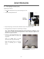
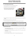
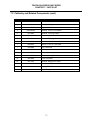
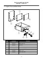
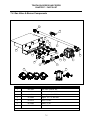
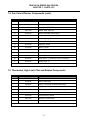
1
Installation & Operation Manual
Model TC25
(Parts Section Included)
Dean, a member of the Commercial Food Equipment Service Association, recommends using
CFESA Certified Technicians.
24-Hour Service Hotline 1-800-551-8633
Price: $6.00
819-5683
MARCH 2002
Please read all sections of this manual and retain for future reference.
This product has been certified as commercial cooking equipment and MUST be installed by
professional personnel as specified. Installation, maintenance and repairs should be performed
by your DEAN FACTORY AUTHORIZED SERVICE CENTER.
CAUTION
Do not store or use gasoline or other flammable vapors and liquids in the vicinity of this or any
other cooking appliance.
CAUTION
Instructions explaining procedures to be followed MUST be posted in a prominent location in
the event the operator detects a gas leak. This information can be obtained from the local gas
company or gas supplier.
WARNING
Improper installation, adjustment, alteration, service or maintenance can cause property
damage, injury or death. Read the installation, operating and maintenance instructions
thoroughly before installing or servicing this equipment.
WARNING
Safe and satisfactory operation of your equipment depends on proper installation. Installation
MUST conform with local codes, or in absence of local codes, with the National Fuel Gas Code,
ANSI Z223.1; The Natural Gas Installation Code, CAN/CGA-B149.1; The Propane Installation
Code, CAN/CGA-B149.2; or The latest edition of the National Electric Code, N.F.P.A. 70.
DANGER
The front ledge of the fryer is not a step. Do not stand on the fryer. Serious injury can result
from slips or contact with the hot oil.
WARNING
Drawings and photos used in this manual are intended to illustrate operational, cleaning and
technical procedures and may not conform to on-site management operational procedures.
WARNING
No structural material on the fryer should be altered or removed to accommodate placement of
the fryer under a hood. Questions? Call the Frymaster/Dean Service Hotline at 1-800-551-8633.
Triathlon Series Gas Fryers
Installation & Operation Manual
TABLE OF CONTENTS
Page #
1.
INTRODUCTION
1-1
1.1
After Purchase
1-1
1.2
Ordering Parts
1-1
1.3
Service Information
1-1
1.4
Safety Information
1-2
2.
IMPORTANT INFORMATION
2-1
2.1
Product Description
2-1
2.2
Principles of Operation
2-1
2.3
Rating Plate
2-1
2.4
Pre-Installation
2-1
2.5
Air Supply and Ventilation
2-3
2.6
Equipment Installed at High Altitudes
2-3
2.7
Receiving and Unpacking Equipment
2-4
3.
INSTALLATION
3-1
3.1
Installing the Fryer
3-1
3.2
Leveling the Fryer
3-1
3.3
Gas Connections
3-2
4.
FRYER OPERATIONS
4-1
4.1
Initial Start-up
4-1
4.2
Boil-Out Procedure
4-3
4.3
Final Preparation
4-5
4.4
Extending Oil/Shortening Life
4-5
4.5
Opening: Beginning the Workday
4-6
4.6
Filtering Basics
4-6
4.7
Closing: End of Day
4-7
4.8
Fryer Shutdown
4-7
Triathlon Series Gas Fryers
Installation & Operation Manual
TABLE OF CONTENTS (cont.)
Page #
5.
PREVENTATIVE MAINTENANCE
5-1
5.1
General
5-1
6.
WIRING DIAGRAMS
6-1
6.1
Robert Shaw Gas-Valve Wiring
6-1
7.
PARTS LIST
7-1
7.1
Accessories
7-1
7.2
Cabinetry and Related Components
7-2
7.3
Frypots, Flues and Drain Valves
7-4
7.4
Gas Valve and Burner Components
7-5
7.5
Thermostat, High-Limit, Pilot and Related Components
7-6
TRIATHLON SERIES GAS FRYERS
CHAPTER 1: INTRODUCTION
1.1 After Purchase
In order to improve service, have the following chart filled in by the Frymaster/Dean Authorized
Service Technician who installs this equipment.
Authorized Service
Technician/FASC
Address
Telephone/Fax
Model Number
Serial Number
Gas Type
1.2 Ordering Parts
Customers may order parts directly from their local factory authorized service center. For this
address and phone number, contact your factory authorized service center or call the Frymaster/Dean
Service Hotline phone number, 1-800-551-8633.
To speed up your order, provide the model number, serial number, gas type, part needed, item part
number (if known), and quantity needed.
Model Number
Serial Number
Optional Equipment
Item Part Number
Type
Quantity Needed
1.3 Service Information
Call the Dean Service Hotline, 1-800-551-8633, for the location of your nearest factory authorized
service center. To assist you more efficiently, always provide the service technician with the model
number, gas type, serial number, and the nature of the problem.
Model Number
Serial Number
Optional Equipment
Nature of Problem
Type
1-1
TRIATHLON SERIES GAS FRYERS
CHAPTER 1: INTRODUCTION
1.4 Safety Information
Before attempting to operate your unit, read the instructions in this manual thoroughly.
Throughout this manual, you will find notations enclosed in double-bordered boxes similar to the
ones below.
CAUTION boxes contain information about actions or conditions that may cause or result in a
malfunction of your system.
CAUTION
Example of a CAUTION box.
WARNING boxes contain information about actions or conditions that may cause or result in
damage to your system, and which may cause your system to malfunction.
WARNING
Example of a WARNING box.
DANGER boxes contain information about actions or conditions that may cause or result in injury
to personnel, and which may cause damage to your system and/or cause your system to malfunction.
DANGER
Hot cooking oil causes severe burns. Never attempt to move a fryer containing hot
cooking oil or to transfer hot cooking oil from one container to another.
1-2
TRIATHLON SERIES GAS FRYERS
CHAPTER 2: IMPORTANT INFORMATION
2.1 Product Description
Dean Triathlon Series gas fryers are energy-efficient, tube-style, gas-fired tabletop units, designcertified by the International Approval Services (AGA/CGA), National Sanitation Foundation
(NSF), and manufactured to their basic performance and application specifications.
All units are shipped completely assembled with accessories packed inside the fryer vessel. All units
are adjusted, tested and inspected at the factory before shipment.
NOTE: The on-site supervisor is responsible for ensuring that operators are made aware of inherent
dangers of operating a deep fat fryer, particularly aspects of oil filtration, draining, and
cleaning of the fryer.
2.2 Principles of Operation
The incoming gas flows through orifices and is mixed with air in the burners to create the correct
ratio for proper combustion. The mixture is ignited at the front end of each heat tube by the pilot
light. A flame spreader slows the flame as it goes through the burner tube. This slower and more
turbulent flame gives much better heat transfer to the walls of the tubes, thereby heating the oil
better.
2.3 Rating Plate
The rating plate is found on the right-side panel of the fryer. Information provided includes the
model and serial number of the fryer, BTU/hr input of the burners, outlet gas pressure in inches
W.C. (mbars) and whether the unit has natural or propane gas orifices.
DANGER
Fryers MUST be connected ONLY to the gas type identified on the attached rating
plate.
2.4 Pre-Installation
A. General: Only a licensed gas fitter should install any gas-fired equipment.
1.
A manual gas shut-off valve must be installed in the gas supply line ahead of the fryers for
safety and ease of future service.
2-1
TRIATHLON SERIES GAS FRYERS
CHAPTER 2: IMPORTANT INFORMATION
2.4 Pre-Installation (cont.)
B. Clearances: The fryer area must be kept free and clear of all combustibles. This unit is designcertified for the following installations:
Commercial installation only (not for household use).
Installation on a non-combustible platform when equipped with factory-supplied 4-inch (10.2 cm)
adjustable legs.
Non-combustible construction with no minimum clearance of the sides and rear, and combustible
construction with a minimum clearance of 6-inches (15-cm) side and 6-inches (15-cm) rear when
equipped with factory-supplied 4-inch (10.2-cm) adjustable legs.
CAUTION
Local building codes usually prohibit a fryer with its open tank of hot oil from being
installed beside an open flame of any type, whether a broiler or the open burner of a
range.
C. Installation Standards:
1.
U.S. installations must meet:
2. Canadian installations must meet:
American National Standard Institute
ANSI Z83.11
American Gas Association
8501 E. Pleasant Valley Road
Cleveland, OH 44131
CAN 1-B149 Installation Codes
Canadian Gas Association
55 Scarsdale Road
Don Mills, ONT, M3B 2R3
National Electrical Code
ANSI/NFPA #70
American National Standard Institute
1430 Broadway
New York, NY 10018
Canadian Electric Code c22.1, part 1
Canadian Standards Association
178 Rexdale Blvd.
Rexdale, ONT, M9W 1R3
NFPA Standards #96 and #211
National Fire Protection Association
470 Atlantic Avenue
Boston, MA 02110
3. CE/EXPORT STANDARDS: Fryer installation must conform with local codes, or in the absence
of local codes, to the appropriate national or European Community (CE) standards.
2-2
TRIATHLON SERIES GAS FRYERS
CHAPTER 2: IMPORTANT INFORMATION
2.5 Air Supply and Ventilation
Keep the area around the fryer clear to prevent obstruction of combustion and ventilation airflow as
well as for service and maintenance.
A. Do not connect this fryer to an exhaust duct.
B. Correct installation and adjustment will ensure adequate airflow to the fryer system.
C. A commercial, heavy-duty fryer must vent its combustion wastes to the outside of the
building. A deep-fat fryer must be installed under a powered exhaust hood, or an exhaust fan
must be provided in the wall above the unit, as exhaust gas temperatures are approximately
500-900°F (260-482°C). Check air movement during installation. Strong exhaust fans in the
exhaust hood or in the overall air conditioning system can produce slight air drafts in the
room.
D. Do not place the fryer’s flue outlet directly into the plenum of the hood, as it will affect the
gas combustion of the fryer.
E. Never store items on shelving over or behind the fryer. Exhaust temperatures can exceed
800°F (427ºC) and may damage or melt items stored near the fryer.
F. Adequate distance must be maintained from the flue outlet of the fryer(s) to the lower edge
of the filter bank. Per NFPA Standards No. 96, a minimum of 18-inches (45-cm) should be
maintained between the flue(s) and the lower edge of the exhaust hood filter.
G. Filters and drip troughs should be part of any industrial hood, but consult local codes before
constructing and installing any hood. The duct system, the exhaust hood and the filter bank
must be cleaned on a regular basis and kept free of grease.
2.6 Equipment Installed at High Altitudes
A. The fryer input rating (BTU/hr) is for elevations up to 2,000 feet (610-m). For elevations
above 2,000 feet (610-m), the rating should be reduced four percent for each additional 1,000
feet (305-m) above sea level.
B. The correct orifices are installed at the factory if operating altitude is known at time of the
customer’s order.
2-3
TRIATHLON SERIES GAS FRYERS
CHAPTER 2: IMPORTANT INFORMATION
2.7 Receiving and Unpacking Equipment
A. Check that the container is upright. Use an outward prying motion - no hammering - to
remove the carton. Unpack the fryer carefully and remove all accessories from the carton.
Do not discard or misplace these, as they will be needed.
B. After unpacking, immediately check the equipment for visible signs of shipping damage. If
damage has occurred, contact the carrier and file the appropriate freight claims. Do not
contact the factory. Shipping damage responsibility is between the carrier and the dealer.
If your equipment arrives damaged:
1. File claim for damages immediately, regardless of extent of damage.
2. Visible loss or damage: Be sure this is noted on the freight bill or express receipt and is
signed by the person making the delivery.
3. Concealed loss or damage: If damage is unnoticed until equipment is unpacked, notify
freight company or carrier immediately, and file a concealed damage claim. This should
be done within 15 days of date of delivery. Be sure to retain container and all packing
materials for inspection.
NOTE: Dean Does Not Assume Responsibility for Damage or Loss Incurred in Transit.
C. Remove all plastic skin from sides, front, and doors of the fryer(s). Failure to do this prior to
initial fryer operation will make the plastic very difficult to remove later.
2-4
TRIATHLON SERIES GAS FRYERS
CHAPTER 3: INSTALLATION
3.1
Installing the Fryer
A. Initial Installation: Legs are installed at the factory. After unpacking, check the legs to ensure
they are properly tightened.
B. Relocating the fryer: Lift the fryer to remove all weight from each leg before moving. Do
not slide the fryer on the legs.
C. If a leg becomes damaged, contact a service agent for immediate repair/replacement.
3.2 Leveling the Fryer
A. All Installations: It is recommended to place the fryer on an even platform.
B. Place a spirit level across the top of the fryer and level the unit both front-to-back and sideto-side. If the unit is not level, it may not function efficiently, and the oil may not drain
properly.
C. Adjust to the high corner and measure with the spirit level. If floor is uneven, level the unit
with the screw adjustments on each leg (see illustration below). Ensure minimum
clearances as discussed in Chapter 2 are maintained during the leveling procedure.
Hold back-up with adjustable
wrench here.
Adjust here to level fryer. Do
not exceed 1" adjustment.
3-1
TRIATHLON SERIES GAS FRYERS
CHAPTER 3: INSTALLATION
3.2 Leveling the Fryer (cont.)
D. Re-leveling: If the fryer is moved, re-level the fryer following the above instructions.
E. The install must be reviewed at the time of installation to ensure it meets the intent of these
instructions.
CAUTION
Fryers must be at room temperature, empty of oil and lifted during movement to
avoid damage and possible bodily injury.
DANGER
Hot shortening can cause severe burns. Avoid contact. Under all circumstances, oil
must be removed from the fryer before attempting to move it to avoid oil spills, and
the falls and severe burns that could occur. This fryer may tip and cause personal
injury if not secured in a stationary position.
3.3 Gas Connections
A. The gas supply (service) line must be the same size or greater than the fryer inlet line. This
fryer is equipped with a 3/4" (19 mm) male inlet. The gas supply line must be sized to
accommodate all the gas-fired equipment that may be connected to that gas supply. Consult
your contractor, gas company, supplier, or other knowledgeable authorities.
CAUTION
All connections must be sealed with a joint compound suitable for the gas being
used, and all connections must be tested with a soapy solution before lighting any
pilots.
B. Rigid Connections: Check any installer-supplied intake pipe(s) visually and clean threading
chips, or any other foreign matter before installing into a service line. If the intake pipes are
not clear of all foreign matter, the orifices will clog when gas pressure is applied. Seal pipe
joints with a sealant resistive to LP gas. When using thread compound on gas piping, use
very small amounts and only on male threads. Use a pipe thread compound that is not
affected by the chemical action of LP gases. DO NOT apply thread compound to the first
two pipe threads—doing so will cause clogging of the burner orifices and control valve.
3-2
TRIATHLON SERIES GAS FRYERS
CHAPTER 3: INSTALLATION
3.3 Gas Connections (cont.)
C. Manual shut-off valve: This gas service supplier-installed valve must be installed in the gas
service line ahead of the fryers in the gas stream and in a position where it can be reached
quickly in the event of an emergency.
D. Regulating Gas Pressure: The fryer and shut-off valve must be disconnected from the gas
supply during any pressure testing of the system.
1. External gas regulators are not normally required on this fryer. A safety control valve
protects the fryer against pressure fluctuations. If the incoming pressure is in excess of
½" PSI (3.45 kPa/35 mbar), a step-down regulator will be required.
CAUTION
The fryer must be isolated from the gas supply piping system by closing its
individual manual shut-off valve during any pressure testing of the gas supply piping
system at pressures equal to or less than ½ PSI (3.45 kPa/35 mbar).
The fryer and its individual shut-off valve must be disconnected from the gas supply
piping system during any pressure testing of the gas supply system at test
pressures in excess of ½ PSI (3.45 kPa/35 mbar).
E. Manifold Pressure: Your local service technician should check the manifold pressure with a
manometer.
1. Check the rating plate for manifold gas pressures. Natural gas units require 3.5" W.C.
(8.71 mbar) and propane requires 10" W.C. (25 mbar).
2. When installing a pressure regulator, ensure the arrow forged into the bottom of the
regulator body is pointing downstream, towards the fryer. The air vent cap is also part
of the regulator and should not be removed.
3. If a vent line from the gas pressure regulator is used, it should be installed in
accordance with local codes or in the absence of local codes, with the National Fuel
Gas Code, ANSI Z223.1-(latest edition).
WARNING
Use a diluted soap solution to find potentially dangerous gas leaks when making
new connections.
F. Regulators can be adjusted in the field, but it is recommended that they not be tampered with
unless the part is known to be out of adjustment or serious pressure fluctuations are found to
exist and can be solved no other way.
3-3
TRIATHLON SERIES GAS FRYERS
CHAPTER 3: INSTALLATION
3.3 Gas Connections (cont.)
G. Only qualified service personnel should make adjustments to the regulators.
H. Orifices: The fryer can be configured to operate on any available gas. The correct safety
control valve, appropriate gas orifices, and pilot burner are installed at the factory. While the
valve can be adjusted in the field, only qualified service personnel should make any
adjustments with the proper test equipment.
WARNING
If gas odors are detected, the gas supply must be shut off at the main shut-off valve.
The local gas company or FASC should be contacted immediately to rectify the
problem.
I.
After connecting the fryer to the gas supply, bleed the gas line of air to ensure that the pilot
will ignite quickly.
3-4
TRIATHLON SERIES GAS FRYERS
CHAPTER 4: FRYER OPERATIONS
4.1 Initial Start-up
A. Cleaning: New units are wiped clean with solvents at the factory to remove any visible signs
of dirt, oil, grease, etc. remaining from the manufacturing process, then coated lightly with
oil. Before any food preparation, wash thoroughly with hot, soapy water to remove any film
residue and dust or debris then rinse out and wipe dry. Also wash any accessories shipped
with the unit. Close the drain valve (see photo below) completely and remove the crumb
screen covering the heating tubes. Ensure the screws holding the thermostat and high-limit
control sensing bulbs (see photo below) into the vessel are tight.
Sensing-bulb location in fry vessel.
Drain valve handle (red).
4.1.1 Pilot Lighting Procedures
Initial Pilot Lighting: All Dean fryers are tested, adjusted and calibrated to sea level conditions
before leaving the factory. Adjustments to assure proper operation of pilot may be necessary on
installation to meet local conditions, low gas pressure, differences in altitude and variations in gas
characteristics. These adjustments correct possible problems caused by rough handling or vibration
during shipment, and are to be performed only by qualified service personnel. These adjustments
are the responsibility of the customer and/or the dealer and are not covered by the Dean warranty.
The inlet pipe at the lower rear of the fryer brings
incoming gas to the pilot safety control valve,
then to the pilot and main burners. The pilot is
located high in the cabinet, left-center, at the base
of the fryer vessel.
Pilot and
thermopile
location
(arrow).
4-1
TRIATHLON SERIES GAS FRYERS
CHAPTER 4: FRYER OPERATIONS
4.1.1 Pilot Lighting Procedures (cont.)
Light the pilot as follows:
1. Turn off the manual shut-off valve on the incoming service line.
2. Turn the operating thermostat off.
Operating
thermostat in
"OFF" position.
3. Depress the pilot gas cock dial on the combination control valve and turn to "OFF".
4. Wait approximately 5 minutes for accumulated gas to disperse.
Note: Inspect high-limit thermostat/temperature probe location prior to filling fry vessel
with water or oil. Ensure that connecting hardware is intact and properly tightened, and
the bulbs are properly attached.
5. Fill the fry vessel with oil/shortening or water
to the bottom OIL LEVEL line scribed on the
vessel back.
NOTE: See Section 4.3.1 for specific
instructions when using solid shortening.
Ensure that heating tubes are covered in
liquid or shortening prior to engaging
burners.
Fill the fry vessel with oil or water to the
bottom OIL LEVEL line.
4-2
TRIATHLON SERIES GAS FRYERS
CHAPTER 4: FRYER OPERATIONS
4.1.1 Pilot Lighting Procedures (cont.)
6. Open the manual shut-off valve on the incoming service line.
7. Apply lighted match or taper to the pilot burner head.
8. Turn the gas cock dial on the control valve to
"Pilot", then depress and hold the dial until
the pilot stays lit (approximately 1 minute).
Gas cock dial in the “pilot” position.
9. If the pilot fails to stay lit, depress the dial and re-light the pilot, depressing the dial longer before
releasing.
10. When the pilot stays lit, turn the gas cock dial to "ON".
11. Turn the operating thermostat on, and then ensure the main burners ignite from the pilot.
WARNING
When checking for burner ignition or performance, do not get too close to the
burners. Slow ignition can cause possible flashback, increasing the potential for
facial and body burns.
4.2 Boil-Out Procedure
A. Pour cleaning solution into the fry vessel and add water to the bottom OIL LEVEL line
scribed in the back of the fry vessel.
B. Set the operating thermostat dial/temperature controller to 225°F (107ºC), just above that of
boiling water.
C. The main burner will ignite.
D. Reset the temperature controller to 200°F (93ºC) when the solution starts to boil.
4-3
TRIATHLON SERIES GAS FRYERS
CHAPTER 4: FRYER OPERATIONS
4.2 Boil-Out Procedure (cont.)
E. The burners will maintain the boil-out solution at a simmer. Simmer the solution for
approximately 45 minutes. Wearing protective gloves, scrub the sides of the fry vessel and
the tubes with the L-shaped Teflon brush, being careful not to disturb the temperature
sensing probe and the high-limit thermostat. USE CARE NOT TO SPLASH SOLUTION
WITH BRUSH- SOLUTION IS HOT!
F. Do not allow the water level to decrease below the bottom OIL LEVEL line in fry vessel
during boil-out operation.
G. After boil out is complete, turn the thermostat dial to "OFF" and drain the solution from the
fry vessel. Place a metal pan or bucket under the drain port to collect the water from the fry
vessel.
H. Close the drain, add fresh water (without boil-out solution) and wash all surfaces of the fry
vessel. Drain again.
I.
Refill the fry vessel with fresh water and vinegar to neutralize any residual boil-out solution.
Wash all surfaces of the fry vessel. Drain completely and wipe down all surfaces of the fry
vessel to completely eliminate water from the vessel.
CAUTION
All drops of water MUST be removed from fry vessel before filling with cooking oil.
Do not turn fryer on to dry… extensive damage will occur to fry vessel and burner
tubes, and ALL applicable warranties will be voided.
NOTE: For a fresh start and prolonged fry vessel life, it is recommended that the boil-out procedure
be performed each time the oil/shortening is changed.
WARNING
Do not go near the area directly over the flue outlet while the fryer is operating.
Always wear oil-proof, insulated gloves when working with the fryer filled with hot
oil.
Always drain hot oil into a metal container. Hot oil can melt plastic buckets and
crack glass containers.
4-4
TRIATHLON SERIES GAS FRYERS
CHAPTER 4: FRYER OPERATIONS
4.3 Final Preparation
WARNING
NEVER set a complete block of solid shortening on top of heating tubes. To do so
will damage the heating tubes and fry vessel, and void the warranty.
4.3.1 Filling Fryer with Cooking Oil/Shortening
A. When using a liquid shortening (cooking oil), fill the fryer to the bottom OIL LEVEL line
scribed into the back of the fryer vessel.
B. When using a solid shortening, first melt it in a suitable container, or cut it into small pieces
and pack it below the heat tubes, between the tubes and on top of the tubes, leaving no air
spaces around the tubes. Do not disturb or bend the sensing bulbs.
C. If the shortening is not melted first, turn the burners "ON" for about 10 seconds, "OFF" for a
minute, etc., until the shortening is melted. If you see smoke coming from the shortening
while melting this way, shorten the "ON" cycle and lengthen the "OFF" cycle. Smoke
indicates potential scorching of the shortening, which will shorten its useful life.
D. Before starting operation, turn the operating thermostat to the probable working
temperature; wait for the temperature to stabilize then check with a high-quality immersion
thermometer to ensure that the thermostat is properly calibrated.
4.4 Extending Shortening/Oil Life
Although 350°F (177°C) is the recommended temperature for most cooking operations, set the fryer
at the lowest possible temperature which produces a high-quality end product. This ensures
maximum life of shortening.
When the fryer is not in use, set the thermostat to a lower temperature than that used during cooking.
Light loads, too, may be cooked at lower temperatures. A good operator should experiment to
determine the optimum temperature and load conditions for the various food items.
4-5
TRIATHLON SERIES GAS FRYERS
CHAPTER 4: FRYER OPERATIONS
4.5 Opening: Beginning the Workday
At the beginning of each work day, always check the fryer to ensure:
1.
The combination or main gas valve is "OFF".
2.
Fry vessel is filled with liquid oil to the bottom OIL LEVEL line scribed into the rear wall
of the fry vessel tank.
To light the fryer:
1.
Open the manual shut-off valve on the incoming service line.
2.
Light the pilot. See Section 4.1.1 for pilot lighting procedures.
After the pilot is lit:
1.
Turn the gas cock dial to "ON".
2.
Turn the thermostat to the desired cooking temperature. Watch to ensure the main burner
ignites from the pilot.
3.
Allow the oil/shortening-filled fry vessel to heat for approximately 30 minutes before
cooking. Oil temperature will stabilize at the desired setpoint, ensuring quality cooking.
4.6 Filtering Basics
CAUTION
When filtering, never leave the filter unit unattended. Oil moving through the lines
can knock the flexible return hose out of the fryer, spraying hot oil and causing
severe burns.
For filtration instructions and troubleshooting, see your operating manual provided with the
filter unit.
Basic rules of filtering are:
ø
The shortening should be filtered at least daily or even more frequently if cooking is heavy.
Filtering ensures long shortening life, better tasting food and minimizes flavors being
transferred from batch to batch.
ø
If using solid shortening, always ensure the hose lines are clear before de-activating the filter
system. Also, hang flexible hose lines up to drain to prevent solid shortening from
solidifying in the lines.
4-6
TRIATHLON SERIES GAS FRYERS
CHAPTER 4: FRYER OPERATIONS
4.7 Closing: End of Day
When closing at night:
ø
Filter the oil in all fryers and drain the flexible hose lines (portable filters).
ø
Cover oil-filled, open fry vessels.
ø
Turn the control knob on the gas valve to "OFF".
4.8 Fryer Shutdown
When closing down for periods longer than overnight:
ø
Drain the shortening and clean the vessel thoroughly.
ø
Discard or filter the shortening, then return filtered shortening to fry vessel. Install fry
vessel cover to prevent shortening contamination.
ø
Non-stainless Fry Vessels Only: If shortening is discarded, lightly coat the inside of nonstainless (mild steel) fry vessels with fresh shortening after cleaning to prevent rusting.
ø
Turn the control knob on the gas valve to "OFF".
ø
Turn the manual valve on the incoming gas service line to "OFF".
ø
Disconnect the portable filter power cord (if used) from the wall socket.
4-7
TRIATHLON SERIES GAS FRYERS
CHAPTER 5: PREVENTATIVE MAINTENANCE
5.1 General
Any equipment works better and lasts longer when maintained properly and kept clean. Cooking
equipment is no exception. Your Triathlon fryer should be kept clean during the working day, and
thoroughly cleaned at the end of each day. Below are recommendations for daily, weekly and
periodic preventative maintenance.
5.1.1 Daily
A. Remove and wash all removable parts.
B. Clean all exterior surfaces of the cabinet. Do not use cleaners, steel wool, or any other
abrasive material on stainless steel.
C. Filter the cooking oil and replace if necessary. The oil should be filtered more frequently
when under heavy use.
5.1.2 Weekly
A. Completely drain the oil from the fryer into a suitable container for disposal. Do not use a
glass or plastic container.
B. Clean the fry-vessel by following boil-out procedures in Chapter 4-2.
CAUTION
Never allow water to boil down and expose the heating tubes. Fry vessel damage
will result.
5.1.3 Periodic
The fryer should be inspected and adjusted periodically by qualified service personnel as part of a
regular kitchen maintenance program.
5-1
TRIATHLON SERIES GAS FRYERS
CHAPTER 5: PREVENTATIVE MAINTENANCE
5.1.4 Stainless Steel Care
WARNING
DO NOT let water splash into the tank of hot oil. It will splatter and can cause severe
burns.
All stainless steel fryer cabinet parts should be wiped regularly with hot, soapy water during the day,
and with a liquid cleanser designed for stainless steel at the end of each day.
A. Do not use steel wool, abrasive cloths, cleansers or powders.
B. Do not use a metal knife, spatula or any other metal tool to scrape stainless steel! Scratches
are almost impossible to remove.
C. If it is necessary to scrape the stainless steel to remove any encrusted materials, soak the area
first to soften the deposit, then use a wood or nylon scraper only.
5-2
TRIATHLON SERIES GAS FRYERS
CHAPTER 6: WIRING DIAGRAMS
6.1 Robert Shaw Gas-Valve Wiring
Combination Gas
Valve
Vent
Robertshaw
PILOT KNOB
Operating
Thermostat
TH
TP
Black
TH
Red
Black
Black
TP
Safety Valve
Red
Red
Red
High-Limit
Yellow (Braided)
THERMOPILE
Orange (Braided)
Red
Red
Black
6-1
TRIATHLON SERIES GAS FRYERS
CHAPTER 7: PARTS LIST
7.1 Accessories
1
2
4
3
5
6
Item
Part Number
Description
1
803-0282
Basket, Fry, 4-1/8 x 5-3/8 x 11"
2
803-0273
Rack, Basket
3
210-1758
Joiner Strip- TC Series
4
210-1220
Basket Hanger
5
803-0278
Brush, Frypot- L-Shaped Teflon
6
106-1915SP
*
803-0197
Cover, Frypot
Fryer’s Friend (Clean-out Rod)
* Not Illustrated
7-1
TRIATHLON SERIES GAS FRYERS
CHAPTER 7: PARTS LIST
7.2 Cabinetry and Related Components
10
8
9
14
2
12
13
11
1
16
7
6
5
4
3
7-2
15
TRIATHLON SERIES GAS FRYERS
CHAPTER 7: PARTS LIST
7.2 Cabinetry and Related Components (cont.)
Item
Part Number
Description
1
211-2943
Panel, Side- Left
2
212-2943
Panel, Side- Right
3
810-2106
Leg, Adjustable
4
200-3035SP
5
201-2944
Channel, Top (Leg)- Right
6
200-2945
Channel, Upper- Front & Back
7
202-2944
Channel, Top (Leg)- Left
8
200-3028
Back, Cabinet
*
809-0816
Screw, 10-16 x ½" Hex Head
*
809-0888
Clip, Tinnerman
9
823-3655
Flue Cap
10
200-3122
Deflector, Heat (Japan)
11
202-1728
Channel, Sliding Door- Left
12
200-2940
Cover, Insulation
13
201-1728
Channel, Sliding Door- Right
14
200-2937
Brace, Cross-Top
15
824-0968
Topcap, TC-25
16
210-1218
Door, Sliding
Channel, Lower- Front & Back
7-3
TRIATHLON SERIES GAS FRYERS
CHAPTER 7: PARTS LIST
7.3 Frypots, Flues and Drain Valves
3
2
4
5
6
1
7
9
8
Item
Part Number
Description
1
823-3290SP
2
200-1734
Shield, Heat- Flue
3
200-1725
Flue, Front
4
200-1724
Flue, Back
5
810-2128
Valve, Drain- 1" (Nut & Washers Included)
6
813-0710
Nipple, 1 x 2-½" NPT BM
7
813-0709
Elbow- 1"- 45°
8
823-3293
Handle, Drain Valve
9
816-0547
Cap, Vinyl- Drain Valve Handle (Red)
Frypot Assembly, TC-25
7-4
TRIATHLON SERIES GAS FRYERS
CHAPTER 7: PARTS LIST
7.4 Gas Valve & Burner Components
2
17
16
12
10
9
15
7
11
8
3
1
2
6
5
4
13
14
Item
Part Number
Description
1
807-3645
Gas Valve- Natural- MV
*
1909
Gas Valve- Propane- MV
2
813-0031
Bushing, ¾ x ½" NPT BM
3
813-0622
Nipple, ½ x 1-½" NPT BM
4
813-0173
Union. ½" NPT
5
813-0062
Elbow, ½" 90°
6
810-2075
Manifold, Gas
*Not Illustrated
7-5
TRIATHLON SERIES GAS FRYERS
CHAPTER 7: PARTS LIST
7.4 Gas Valve & Burner Components (cont.)
Item
Part Number
Description
7
813-0154
Plug, 1/8" NPT Hex Head
8
813-0165
Elbow, Street 90°
9
813-0694
Nipple, ½ x 25" NPT BM
*
200-1745
Shield, Heat- Pipe Inlet
10
810-2219
Orifice Assembly, Natural (#47)
*
1826-5
Orifice Assembly, Propane (#56)
11
810-2225
Collar, Aligning- Orifice
12
823-3292
Bracket, Burner
13
810-2336
Spreader, Flame
14
810-2286
Burner, Center
*
810-2285
Burner, Right
*
810-2279
Burner, Left
15
823-3602
Shield, Front
16
810-0179
Plug, Button- ½" Diameter Hole (Front Shield)
17
810-2043
Clamp, Pipe- ½"
*Not Illustrated
7.5 Thermostat, High-Limit, Pilot and Related Components
Item
Part Number
Description
*
807-3515
Thermostat, Sunne
*
816-0546
Knob, Thermostat
*
810-2047
Spring, Thermostat Probe Bulb Mounting
*
807-3516
High-Limit, 435°F
*
810-2046
Spring, High-Limit Probe Bulb Mounting
*
200-1219
Bracket, Thermostat and High-Limit
*
810-2158
Pilot Assembly, Natural
*
200-1732
Bracket, Pilot Assembly
*
810-2033
Thermopile
*Not Illustrated
7-6
Dean, 8700 Line Avenue, PO Box 51000, Shreveport, Louisiana 71135-1000
Shipping Address: 8700 Line Avenue, Shreveport, Louisiana 71106
TEL 1-318-865-1711
FAX (Parts) 1-318-219-7140
PRINTED IN THE UNITED STATES
FAX (Tech Support) 1-318-219-7135
SERVICE HOTLINE
1-800-551-8633
Price: $6.00
819-5683
MARCH 2002