1
Ramsey Electronics Model No.
RB1
Got a problem with furry intruders in your yard or garden? Here
is a professional strength repeller designed to send those pesky
critters running with their tails between their legs. A convenient,
nature friendly method of keeping animals away from where you
don’t want them
•
Around 4 watts of screaming high frequency audio. Inaudible
to humans, but a terror to animals.
•
3 settings for different levels of coverage
•
Built-in piezo high efficiency speaker
•
External trigger input for use with motion sensors and other
detectors.
•
Operates on 9 to 15 volts DC or AC.
•
LED indicator shows when unit is operating.
•
Informative manual answers questions on theory, hookups
and uses - enhances resale value, too!
•
Add our rugged metal case for years of outdoor or indoor
use.
RB1
RB-1 • 1
1
PARTIAL LIST OF AVAILABLE KITS
RAMSEY TRANSMITTER KITS
• FM25B FM Stereo Transmitter
• AM1 AM Transmitter
• TV6 Television Transmitter
• FM100B Professional FM Stereo Transmitter
RAMSEY RECEIVER KITS
• FR1 FM Broadcast Receiver
• AR1 Aircraft Band Receiver
• SR2 Shortwave Receiver
• AA7 Active Antenna
• SC1 Shortwave Converter
RAMSEY HOBBY KITS
• SG7 Personal Speed Radar
• SS70A Speech Scrambler
• MD3 Microwave Motion Detector
• PH10 Peak hold Meter
• STC1 Stereo Transmitter Companion
• SHA1 Headphone Amplifier
RAMSEY AMATEUR RADIO KITS
• DDF1 Doppler Direction Finder
• HR Series HF All Mode Receivers
• QRP Series HF CW Transmitters
• CW7 CW Keyer
• CPO3 Code Practice Oscillator
• QRP Power Amplifiers
RAMSEY MINI-KITS
Many other kits are available for hobby, school, scouts and just plain FUN. New
kits are always under development. Write or call for our free Ramsey catalog.
RB1 RAT BLASTER INSTRUCTION MANUAL
Ramsey Electronics publication No. MRB1 Revision 1.1
First printing: Feb. 1996 MRW/GMG
COPYRIGHT 1996 by Ramsey Electronics, Inc. 590 Fishers Station Drive, Victor, New York
14564. All rights reserved. No portion of this publication may be copied or duplicated without the
written permission of Ramsey Electronics, Inc. Printed in the United States of America.
RB1
2
Ramsey Publication No. MRB1
Price $5.00
KIT ASSEMBLY
AND INSTRUCTION MANUAL FOR
RB1
RAT BLASTER
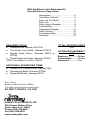
TABLE OF CONTENTS
Introduction .....................................4
How Does It Work? .........................5
Learn As You Build .........................6
Parts List .........................................7
Parts Layout Diagram .....................8
Construction....................................9
Schematic Diagram ......................10
Initial Testing .................................15
Troubleshooting ............................16
Warranty .......................................19
RAMSEY ELECTRONICS, INC.
590 Fishers Station Drive
Victor, New York 14564
Phone (585) 924-4560
Fax (585) 924-4555
www.ramseykits.com
RB1
3
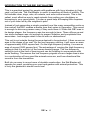
INTRODUCTION TO THE RB1 RAT BLASTER
This is a practical project for people with problems with furry intruders in their
yard, not just rats. The Rat Blaster is useful in repelling all kinds of wildlife. The
list includes deer, dogs, cats, all rodents, and even some insects. This is the
safest, most effective way to repel animals from eating your shrubbery or
burrowing in your carrot patch. It is also a great help at keeping little surprises
out of your lawn left by the neighbor’s pets.
Instead of just generating a single constant tone like many competitive units on
the market, the RB1 creates a warble tone that varies in frequency. This sound
is enough to drive any person crazy if they could hear it. When the RB1 was in
its design stages, the frequency was low enough to hear. Three offices up and
two doors between was not enough to prevent irritation and complaints from
associates. Just imagine what it can do with no obstructions!
This unit is set outside facing the area desired to be protected. It then covers an
area in the shape of an oval. On the low frequency setting, it will cover an area
of approximately 4000 square feet. On the high frequency setting, it covers an
area of around 2500 square feet. The advantage of running the high frequency
setting is that it is well out of the human hearing range. The low frequency
setting is just at the limit of hearing and can be irritating to some people with
acute hearing. The reason the low frequency signals cover a larger area is due
to a combination of how good the animals ears are, and how directional the
sound is from the transducer.
Built into an easy to mount case of durable construction, the Rat Blaster will
operate for years, providing your yard and garden with animal protection. This
is truly the gardener’s dream come true!
RB1
4
HOW DOES IT WORK?
Here is where we get into a little circuit analysis. If you just want to plug it in and
start scaring off critters, you can skip this section. Otherwise here is some
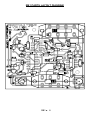
insight into why and how this RB1 works. We will use the schematic located at
the center of the manual to analyze the circuit.
We will begin with the IC marked NE555, U1. This is a simple, free running
oscillator circuit which is used to generate the lower frequency warble rate of
the signal. This rate varies from around 1Hz to 10Hz. The output of this
oscillator is a 12V square wave until it is sent through R2 into C7. These parts
filter the waveform into a sawtooth waveform.
U2, the XR-2209 is set up to be a voltage controlled oscillator running between
15kHz and 50kHz. The higher the voltage seen on pin 4 of U2, the higher the
frequency produced on pin 7 of U2. When the low frequency sawtooth signal
from U1 is sent to pin 4, the high frequency signal of U2 modulates or “warbles”
at a rate of U1’s output frequency.
S2 controls the average DC voltage of the sawtooth by adjusting the rate of
discharge of C7. The less resistance seen from pin 4 to ground, the faster C7
discharges. The faster C7 is discharged, the lower the average voltage of the
sawtooth waveform is. In turn, the lower the average voltage on the sawtooth,
the lower the average frequency on pin 7 of U2 allowing this unit to cover a
larger area.
The output of U2 is then sent to some logic which enables or disables the
speaker driver circuitry depending on what signal is seen on pin 2 and 6 of U3.
When these pins are at a logic ‘0’, or 0 volts, the transducer driver is enabled,
and when it is ‘1’, or 12 volts, it is disabled.
The speaker driver section consists of a push-pull circuit controlled by U3:D, B,
and C. U3:B inverts the signal from U3:A so that when pin 3 is high (12 volts)
pin 4 is low (0 volts). U3:D and U3:C are set up as inverting buffers to drive the
transistors that drive the transducer.
The speaker driver also consists of the four transistors surrounding SP1 which
provide more power capability than what U3 offers. When U3 pin 11 is high, Q4
is turned on, and Q1 is turned off. This presents about 12 volts on one side of
the transducer. While pin 11 is high, pin 10 is low, which turns on Q2 and Q3
off, pulling the other lead of the transducer to near 0 volts. Now there are
almost 12 volts across SP1, allowing the transducer to produce sound. On the
next half of the cycle, the transistors that were off are turned on, and the ones
that were on are shut off. Now there are 12 volts across the transducer
connected in the opposite direction from before. This is all done at a rate of
around 15,000 to 50,000 times a second, producing the high frequency signal
to scare off the beasties.
RB1
5
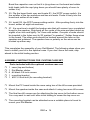
NOTE TO NEWCOMERS: If you are a first time kit builder you may find this
manual easier to understand than you may have expected. Each part in the kit
is checked off as you go, while a detailed description of each part is given. If
you follow each step in the manual in order, and practice good soldering and kit
building skills, the kit is next to fail-safe. If a problem does occur, the manual
will lead you step by step through the troubleshooting guide until you find the
problem and are able to correct it.
RAMSEY “LEARN-AS-YOU-BUILD” ASSEMBLY STRATEGY
Be sure to read through all of the steps, and check the boxes as you go to be
sure you didn't miss any important steps. Although you may be in a hurry to see
results, before you switch on the power, check all wiring and capacitors for
proper orientation. Also check the board for any possible solder shorts, and/or
cold solder joints. All of these mistakes could have detrimental effects on your
kit - not to mention your ego!
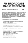
Kit building tips:
Use a good soldering technique - let your soldering iron tip gently heat the
traces to which you are soldering, heating both wires and pads simultaneously.
Apply the solder to the iron and the pad when the pad is hot enough to melt the
solder. The finished joint should look like a drop of water on paper - somewhat
soaked in.
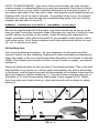
Mount all electrical parts on the top side of the board provided. This is the side
that has little or no traces on it. When parts are installed, the part is placed flat
to the board, and the leads are bent on the backside of the board to prevent the
part from falling out before soldering (1). The part is then soldered securely to
the board (2-4), and the remaining lead length is then clipped off (5). Notice
how the solder joint looks close up, clean and smooth with no holes or sharp
points (6).
RB1
6
RAMSEY RB1 PARTS LIST
Semiconductors
❒ 1 4001 Quad dual input NOR gate (U3)
❒ 1 XR-2209 voltage controlled oscillator (U2)
❒ 1 NE555 timer (U1)
❒ 2 2N3904 NPN transistors (TO92 package marked 3904) (Q3,4)
❒ 2 221-334 PNP transistors (Flat TO92 package marked 221-334) (Q1,2)
❒ 1 1N4002 rectifier diode (D1)
❒ 1 Large red LED (D2)
Resistors
❒ 4 6.2 ohm resistors [blue-red-gold](R12,R13,R14,R15)
❒ 1 2.2K ohm resistor [red-red-red](R16)
❒ 1 3.9K ohm resistor [orange-white-red](R10)
❒ 1 4.7K ohm resistor [yellow-violet-red](R8)
❒ 1 6.8K ohm resistor [blue-gray-red](R7)
❒ 2 10K ohm resistors [brown-black-orange](R6,R11)
❒ 1 22K ohm resistor [red-red-orange](R1)
❒ 2 47K ohm resistors [yellow-violet-orange](R5,R9)
❒ 1 100K ohm resistor [brown-black-yellow](R3)
❒ 2 150K ohm resistors [brown-green-yellow](R2,R4)
Capacitors
❒ 1 330uF electrolytic capacitor (C1)
❒ 3 10uF electrolytic capacitors (C4,C6,C7)
❒ 3 .1uF ceramic capacitors [Marked .1 or 104](C2,C3,C8)
❒ 1 .001 ceramic capacitor [Marked .001 or 102](C5)
Miscellaneous
❒ 1 3PDT power setting switch (S2)
❒ 1 SPDT power switch (S1)
❒ 1 Power jack (J1)
❒ 1 stereo jack (J2)
❒ 1 piezo power speaker horn (SP1)
RB1
7
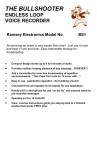
RB1 PARTS LAYOUT DIAGRAM
RB1
8
CONSTRUCTION OF THE RAT BLASTER:
Sort out your parts to begin with, making sure you have all of the parts required.
You can use old egg cartons to hold various parts to make them easier to find.
We will begin building the kit starting with the lower profile parts to make it
easier for us to mount them. You will want to use the parts layout diagram to
assist you in finding where the components go.
For each part, our word "install" always means these steps:
1. Pick the correct part value to start with.
2. Insert it into the correct PC board location, making sure the part is
mounted flush to the PC board unless otherwise noted.
3. Orient it correctly, following the PC board drawing and the written
directions for all parts - especially when there's a right way and a wrong
way to solder it in. (Diode bands, electrolytic capacitor polarity, transistor
shapes, dotted or notched ends of IC's, and so forth.)
4. Solder all connections unless directed otherwise. Use enough heat and
solder flow for clean, shiny, completed connections.
❒
1. Orient the board in the same direction as the parts layout diagram.
❒
2. Install R6, a 10K ohm resistor (brown-black-orange).
❒
3. Install R4, a 150K ohm resistor (brown-green-yellow).
❒
4. Install R5, a 47K ohm resistor (yellow-violet-orange).
❒
5. Install R7,a 6.8K ohm resistor (blue-gray-red).
❒
6. Install R2, another 150K ohm resistor (brown-green-yellow).
❒
7. Install R3, a 100K ohm resistor (brown-black-yellow).
❒
8. Install R9, a 47K ohm resistor (yellow-violet-orange).
❒
9. Install R10, a 3.9K ohm resistor (orange-white-red).
❒
10. Install R8, a 4.7K ohm resistor (yellow-violet-red).
RB1
9
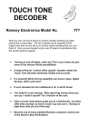
RB1 SCHEMATIC DIAGRAM
RB1
10
RB1
11
❒
11. Install D1, the 1N4002 power diode. This diode prevents the possibility
of someone using the incorrect power supply and inadvertently connecting
the power backwards. Make sure the banded end of the diode (cathode) is
installed in the same direction as shown in the parts layout diagram.
❒
12. Install R16, a 2.2K ohm resistor (red-red-red).
❒
13. Install R1, a 22K ohm resistor (red-red-orange).
❒
14. Install R12, R13, R14, and R15 all 6.2 ohm resistors (blue-red-gold).
❒
15.Install R11, a 10K ohm resistor (brown-black-orange).
❒
16. Install C7, one of the 10uF electrolytic capacitors. Make sure to mount
this part in the correct direction! If you look at the component you will see a
stripe down one side, usually indicating the negative (-) terminal of the
component. You will notice on the parts layout diagram that the hole for the
positive terminal is denoted. You will want to install this component with the
positive (+) lead in the same orientation as shown in the parts layout
diagram. If you do not install it correctly, you will end up with all sorts of
problems in the circuit. Before
soldering, place the leads in the
appropriate holes, then carefully bend
+-20%
+-20%
+-20%
+-20%
the capacitor over making sure the
leads don’t cross and remain as short
as possible. Then solder the
component.
❒
17. Install C4, another 10uF electrolytic capacitor using the same procedure
as with C7. Pay close attention to polarity orientation!
❒
18. Install C6, another 10uF electrolytic capacitor. Make sure that the part is
installed in the correct orientation, bend the component over in the same
orientation as shown in the parts layout diagram, then solder.
❒
19. Install U1, the NE555 IC. Notice that one end of the chip is marked with
a dot, notch, or band. Be sure to orient this end as shown in the parts layout
diagram and the silkscreen. You may use an IC socket if you wish but be
aware that our technicians see more repair problems due to sockets than
due to chips burned out from overheating with a soldering iron. Be careful
not to “bridge” the pins together.
❒
20. Install U3, the 4001 IC. Be sure to orient it as shown on the parts layout.
❒
21. Install U2, an XR-2209 IC, making sure to orient it correctly.
❒
22. Install C5, a .001uF disc capacitor (marked .001 or 102).
RB1
12
❒
23. Install C3, a .1uF disc capacitor (marked .1 or 104).
❒
24. Install C8, another .1uF disc capacitor (marked .1 or 104).
❒
25. Install C2, the last .1uF disc capacitor (marked .1 or 104).
❒
26. It is time to install the transistors, starting with Q3, a 2N3904.
Transistors have three legs and must be mounted correctly. Notice that the
part has a flat side. Orient the flat side as shown on the parts layout. To
install, slide the legs through the circuit board and push the component as
close to the board as possible without straining the leads. Solder all three
connections securely.
❒
27. Install Q2, a PNP transistor (marked 221334). This transistor and Q1
each appear to have two flat sides. Orient the part using the larger flat side
with no writing on it and install Q2 just as you did Q3 in step 26.
❒
28. In the same way, install Q1 the other 221334 transistor.
❒
29. Install Q4 the last transistor, a 2N3904. Watch your orientation.
❒
30. Before installing the larger parts, we have to install JMP1. From a scrap
component lead, form this jumper and install it as you would a resistor.
Jumpers act like small “bridges” to route traces to the top side of the board
and over obstacles (other traces).
❒
31. Now we will install the stereo jack, J2. It is located next to JMP1. This
part only fits into the PC board one way and should be placed with the body
of the part as close to the board as possible. Gently bend the tabs over if
necessary to hold the part in place and solder all three connections.
❒
32. The next part to be installed is J1, the power jack. Press it firmly into the
board and solder all three leads.
There are two components in the center of the PC board that have not been
soldered in yet. Before installing the switches, we will install these parts.
❒
33. Install D2, the large red LED. Note that one of the two leads is longer.
This is the anode and should be placed in the hole closest to the outline for
C1. Install the part with the leads standing about an eighth of an inch above
the board and solder both legs.
❒
34. C1, a 330uF electrolytic capacitor, must be installed on the solder side
of the PC board. This part also has a polarity which is marked on the top
side of the board. One side of the capacitor has a stripe which denotes the
negative side, while the PC board silkscreen marks the positive side. Be
sure to orient the part correctly. On the back or solder side of the board,
insert C1’s leads through to the top side, making sure the polarity is right.
RB1
13
Bend the capacitor over so that it is lying down on the board and solder
both leads (with the cap lying down you should have plenty of room to
solder it in).
❒
35. Flip the board back over and locate S1, the SPDT power switch. It is
the smaller of the two switches and has six leads. Press it firmly into the
board and solder all six leads.
❒
36. Install S2, the 3PDT power setting switch. After pushing firmly into the
board, solder all eight connections.
❒
37. It is now time to install the hookup wire that will connect your completed
board to the speaker. Strip back all four ends of the wire provided about an
eighth of an inch and lightly “tin” them with solder. One pair of ends should
be inserted in the holes next to S2 marked “to speaker”. Solder these wires
to the board. The other ends should be hooked around the tabs on the
speaker and soldered. The speaker has no polarity so the wires can be
hooked up either way.
This completes the assembly of your Rat Blaster! The following steps show you
how to install your kit in the optional case. If you don’t have the case, skip
ahead to the initial testing section.
ASSEMBLY INSTRUCTIONS FOR CUSTOM CASE SET
Parts included with the optional custom case set:
❒
❒
❒
❒
❒
1
1
6
1
1
❒
Mount the PC board inside the case using two of the #6 screws provided.
❒
Mount the speaker inside the case and attach it using two more #6 screws.
❒
The final two #6 screws are for attaching the top cover to the bottom cover.
You may want to wait until after initial testing to screw the top cover on.
❒
The mounting bracket can be attached once a suitable place is found to
mount your Rat Blaster.
case (top and bottom)
Rat Blaster sticker
#6 black 3/8 inch screws
mounting bracket
#20 1/4 inch bolt (for mounting bracket)
RB1
14
INITIAL TESTING:
❒
Connect a suitable 12 volt supply to J1- either 12 VAC or 12 VDC ( positive
tip).
❒
Set the frequency range switch to LOW.
❒
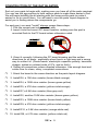
BEFORE turning on the power, please read the WARNING below (also on
the back of the case)
WARNING
TO ELIMINATE ANY POSSIBLE RISK OF HEARING LOSS, AVOID NEARBY
EXPOSURE TO THE “RAT BLASTER” SOUNDS. THIS UNIT CAN CAUSE
PERMANENT HEARING DAMAGE.
❒
Turn on the power. The LED should light and you should hear an annoying,
high pitched whine. If so, your Rat Blaster is working and ready to chase
away those nasty critters bothering you. You can change the frequency
range to whatever you desire and place the Rat Blaster wherever it is
needed. The unit is tested on low frequency because it is easier for the
human ear to hear. If it is functioning on low, rest assured that it will
function on medium and high frequency too!
❒
If you are not able to hear the high frequency noise and you have a
voltmeter,you can still check to be sure that your Rat Blaster is functioning.
Set the meter to AC volts and with the meter leads across the speaker
terminals you should see about 12 to 15 VRMS on a typical meter. Voltage
readings will depend on the supply used, of course. If you are getting a
reading of some kind even if it is not 12 –15 volts, this can be due to the
variations in different meters but the voltage reading indicates that the unit
is working. If you’re using a scope, a bench power supply will give you
readings of about 33vpp and our AC125 will read about 25vpp.
If you hear no sound and get no voltmeter reading, it is time to consult the
troubleshooting guide.
RB1
15
TROUBLESHOOTING GUIDE:
If your RB1 does not work at all, recheck the following:
❒
❒
❒
❒
correct orientation of diodes, electrolytic capacitors, ICs and transistors.
resistor color codes; 2.2K and 22K resistors are easily confused. The
orange and red color bands look the same under certain conditions. This is
also true for 4.7K and 47K resistors.
soldering; solder bridges and cold solder joints are two of the most common
problems we see on kits returned for repair. You shouldn’t need a
magnifying glass. If a connection is suspect, resolder it!
the power supply; make sure you have 12 volts and if you’re using a DC
supply, be sure that the tip is positive.
If you have given your kit a thorough visual inspection, touched up any solder
connections that look less than perfect, and still haven’t found the problem, you
are ready for some more serious troubleshooting. There are several points that
can be checked with a voltmeter or an oscilloscope and may lead you to the
problem. If you have no test equipment of any kind and can’t borrow a meter
from someone, move on to the warranty section at the back of the manual. If
you have a voltmeter you can check the following:
❒
❒
❒
Across the speaker terminals you should see about 12 to 15 VRMS. If you
get any reading move on to the next step.
You can check the output of U1 on pin 3. On AC, the voltage will vary from
0.4 to 2.2 VRMS. On DC, the voltage will vary from 0.2 to 10.5 VDC. The
best way to see what is happening is to check pin 3 with an oscilloscope.
You should see a square wave from zero (0) to twelve (12) volts (or source
voltage if you’re using something other than a 12 volt input) with a period of
two (2) seconds.
If the output of U1 is good, check the output of U2 at pin 7. You should have
about 6 VDC, or approximately 11.5 vpp (AC volts will be changing
constantly. On the oscilloscope you will see a square wave, 0 to 12 (or
source) volts that is sweeping back and forth. The period of the wave will
depend on the frequency setting at S2. If the square wave is not sweeping
but is steady, the problem is in or around the NE555 IC.
The same signal seen on pin 7 of U2 should also be on pin 3 and pin 11 of U3.
If you have a good signal at pin 3 and not at pin 11, U3 may be bad. If you have
a good signal at pin 11 and nothing across the speaker terminals, the problem
is centered around the speaker - Q1, 2, 3, or 4 or R12, 13, 14, or 15.
RB1
16
USING YOUR RAT BLASTER:
Certain animals are affected by different frequency settings and other factors
that you can change to repel the pests that are bothering you. The information
below should help you get the best results from your Rat Blaster.
DOGS: Dogs respond best to the low frequency setting. This is due to the fact
that as they age, domestic dogs lose some of their high frequency hearing.
(That’s why Old Yeller doesn’t seem to hear me when I whistle for him!?!)
CATS: Cats are best repelled using the high frequency setting. If you’re trying
to get rid of both dogs and cats at the same time, the medium or low setting
should be best.
FERAL CATS AND OTHER WILD ANIMALS: Any setting may be useful
against a number of different wild animals because of their acute hearing.
COMMON GARDEN AND YARD PESTS: These would include; rats, ferrets,
weasels, opossums, raccoons, skunks, and woodchucks. The low frequency
setting works best on these types of critters.
DEER: Deer respond best to the medium frequency setting. They can be
difficult to repel and keeping them out of your yard and garden may require
more diligence on your part. You should move your Rat Blaster around and
even change the height at which it is mounted. The frequency setting can also
be changed periodically when using the Rat Blaster to repel deer. A motion
sensor with its output applied to J2 is the most effective way to keep deer off
your property.
CONNECTING AN EXTERNAL TRIGGER:
If you would like to trigger the RB1 externally, you may do so by using a 1/8
inch stereo plug and the external trigger input. The tip of the stereo plug should
be held high (disabling the unit) until switched or triggered low. By pulling pin 6
of U3:B low, the RB1 is enabled and will continue to generate the high
frequency signal until pin 6 is again pulled high. Be sure to use a stereo plug
only! A mono phono plug will short your +12 volt input to ground.
RB1
17
RB1
18
The Ramsey Kit Warranty
Please read carefully BEFORE calling or writing in about your kit. Most problems can be
solved without contacting the factory.
Notice that this is not a "fine print" warranty. We want you to understand your rights and ours too!
All Ramsey kits will work if assembled properly. The very fact that your kit includes this new manual
is your assurance that a team of knowledgeable people have field-tested several "copies" of this kit
straight from the Ramsey inventory. If you need help, please read through your manual carefully. All
information required to properly build and test your kit is contained within the pages!
1. DEFECTIVE PARTS: It's always easy to blame a part for a problem in your kit, Before you
conclude that a part may be bad, thoroughly check your work. Today's semiconductors and passive
components have reached incredibly high reliability levels, and its sad to say that our human
construction skills have not! But on rare occasions a sour component can slip through. All our kit
parts carry the Ramsey Electronics Warranty that they are free from defects for a full ninety (90)
days from the date of purchase. Defective parts will be replaced promptly at our expense. If you
suspect any part to be defective, please mail it to our factory for testing and replacement. Please
send only the defective part(s), not the entire kit. The part(s) MUST be returned to us in suitable
condition for testing. Please be aware that testing can usually determine if the part was truly
defective or damaged by assembly or usage. Don't be afraid of telling us that you 'blew-it', we're all
human and in most cases, replacement parts are very reasonably priced.
2. MISSING PARTS: Before assuming a part value is incorrect, check the parts listing carefully to
see if it is a critical value such as a specific coil or IC, or whether a RANGE of values is suitable
(such as "100 to 500 uF"). Often times, common sense will solve a mysterious missing part
problem. If you're missing five 10K ohm resistors and received five extra 1K resistors, you can
pretty much be assured that the '1K ohm' resistors are actually the 'missing' 10 K parts ("Hum-m-m,
I guess the 'red' band really does look orange!") Ramsey Electronics project kits are packed with
pride in the USA. If you believe we packed an incorrect part or omitted a part clearly indicated in
your assembly manual as supplied with the basic kit by Ramsey, please write or call us with
information on the part you need and proof of kit purchase
3. FACTORY REPAIR OF ASSEMBLED KITS:
To qualify for Ramsey Electronics factory repair, kits MUST:
1. NOT be assembled with acid core solder or flux.
2. NOT be modified in any manner.
3. BE returned in fully-assembled form, not partially assembled.
4. BE accompanied by the proper repair fee. No repair will be undertaken until we have received the
MINIMUM repair fee (1/2 hour labor) of $25.00, or authorization to charge it to your credit
card account.
5. INCLUDE a description of the problem and legible return address. DO NOT send a separate
letter; include all correspondence with the unit. Please do not include your own hardware
such as non-Ramsey cabinets, knobs, cables, external battery packs and the like. Ramsey
Electronics, Inc., reserves the right to refuse repair on ANY item in which we find excessive
problems or damage due to construction methods. To assist customers in such situations,
Ramsey Electronics, Inc., reserves the right to solve their needs on a case-by-case basis.
The repair is $50.00 per hour, regardless of the cost of the kit. Please understand that our
technicians are not volunteers and that set-up, testing, diagnosis, repair and repacking and
paperwork can take nearly an hour of paid employee time on even a simple kit. Of course, if we find
that a part was defective in manufacture, there will be no charge to repair your kit (But please
realize that our technicians know the difference between a defective part and parts burned out or
damaged through improper use or assembly).
4. REFUNDS: You are given ten (10) days to examine our products. If you are not satisfied, you
may return your unassembled kit with all the parts and instructions and proof of purchase to the
factory for a full refund. The return package should be packed securely. Insurance is recommended.
Please do not cause needless delays, read all information carefully.
RB1
19
RB1 Rat Blaster Pest Eliminator Kit
Quick Reference Page Guide
Introduction ..................................... 4
How Does It Work? ........................ 5
Learn As You Build ......................... 6
Parts List ........................................ 7
Parts Layout Diagram ..................... 8
Construction ................................... 9
Schematic Diagram ...................... 10
Initial Testing ................................ 15
Troubleshooting ............................ 16
Warranty ....................................... 19
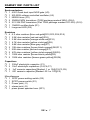
REQUIRED TOOLS
• Soldering Iron Ramsey WLC100
• Thin Rosin Core Solder Ramsey RTS12
• Needle Nose Pliers Ramsey MPP4 or
RTS05
• Small Diagonal Cutters Ramsey RTS04
<OR> Technician’s Tool Kit TK405
ADDITIONAL SUGGESTED ITEMS
• Holder for PC Board/Parts Ramsey HH3
• Desoldering Braid Ramsey RTS08
• Digital Multimeter Ramsey M133
Price: $5.00
Ramsey Publication No. MRB1
Assembly and Instruction manual for:
RAMSEY MODEL NO. RB1
RAMSEY ELECTRONICS, INC.
590 Fishers Station Drive
Victor, New York 14564
Phone (585) 924-4560
Fax (585) 924-4555
www.ramseykits.com
RB1
20
TOTAL SOLDER POINTS
118
ESTIMATED ASSEMBLY
TIME
Beginner ............ ..2.5 hrs
Intermediate......... 1.5 hrs
Advanced ............. 1 hr