1
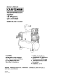
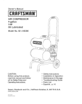
Owner's Manual
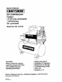
AIR COMPRESSOR
3-gallon
1.5 HP (max developed)
1 HP Running
Oil Lubricated
Model No. 921.153100
CAUTION:
Before using this product,
read this manual and follow
all its Safety Rules and
Operating Instructions.
Sears,
Roebuck
www.sears.com/craftsman
06/17#2004
Part NO. E100731
and Co., Hoffman
•
•
•
•
•
•
Safety instructions
Installation & Operation
Maintenance & Storage
Troubleshooting Guide
Parts List
Espa_ol, p. 10
Estates,
IL 60179 U.S.A.
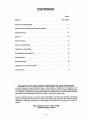
TABLE OF CONTENTS
Page
Warranty ...................... ,................................................................................
see below
Safety Instructions .................................................................................................
1
Important Safety Instructions & Guidelines ...........................................................
1
Specifications .........................................................................................................
2
Glossary ................................................................................................................
2
Duty Cycle .............................................................................................................
2
Parts & Features ...................................................................................................
3
installation & Assembly .........................................................................................
4
Operating Procedures ...........................................................................................
5
Maintenance ..........................................................................................................
6
Storage ..................................................................................................................
6
Troubleshooting Guide ..........................................................................................
7
Parts List.................................................................................................................
8
EspaSol....................................................................................................................
10
Service Number. .........................................................................................
ONE YEAR
FULL
WARRANTY
ON CRAFTSMAN
back cover
AIR COMPRESSOR
If this Craftsman Air Compressor fails due to manufacturer's defects in material or workmanship
within one year of the date of purchase, RETURN IT TO THE NEAREST SEARS STORE OR
SERVICE CENTER IN THE UNITED STATES and it will be replaced or repaired (at our option),
free of charge.
If this Air Compressor is used for commercia?or rental purposes, this warranty applies for only 90
days from the date of purchase. This warranty gives you specific legal rights and you may also
have other rights which vary from state to state.
Sears, Roebuck and Co., Dept. 817WA,
Hoffman Estates, IL 60179
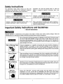
Safety Instructions
The information listed below should be read and
understood by the operator. This information is given to
_rotect the user while operating and storing the air
compressor. We utnize the symbols below to allow the
reader to recognize important information about their
safety.
Indicates an imminently hazardous situation which, if not
avoided, will result in death or serious injury.
Indicates a potentially hazardous situation which, if not
avoided, may result in minor or moderate injury.
Indicates a potentially hazardous situation which, if not
avoided, could result in death or serious injury
When used without the safety alert symbol indicates a
potentially hazardous situation which, if not avoided, may
result in property damage.
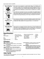
Important Safety Instructions and Guidelines
• Save all instructions
Improper operation or maintenance of this product could result in serious injury and/or property damage. Read and
understand all of the warnings and safety instructions provided before using this equipment.
The air compressor should be operated on a dedicated 15 amp circuit. If the circuit does
not have 15 free amps available, a larger circuit must be used. Always use more air
hose before utilizing extension cords. All extension cords used must be 12 gauge with
a maximum length of 25 ft. The circuit fuse type must be a time delay. Low voltage could
cause damage to the motor.
Risk of Moving Parts
If the air compressor is in operation, all guards and covers should be attached or
installed correctly. If any guard or cover has been damaged, do not operate the
equipment until the proper personnel has correctly repaired the equipment. The power
cord should be free of any moving parts, twisting and/or crimping while in use and while
in storage.
Risk of Burns
There are surfaces on your air compressor that while in operation and thereafter can
cause serious burns if touched. The equipment should be allowed time to cool before
any maintenance is attempted. Items such as the compressor pump and the outlet tube
are normally hot during and after operation.
N
Risk of Falling
Operation of the air compressor should always be in a position that is stable. Never use
the air compressor on a rooftop or elevated positionthat could allow the unit to fall or
be tipped over. Use additional air hose for elevated jobs.
Risk from
Always wear ANSI Z87.1 approved safety glasses with side shields when the air
compressor is in use. Turn off the air compressor and drain the air tank before
performing any type of maintenance or disassembly of the hoses or fittings. Never point
any nozzle or sprayer toward any part of the body or at other people or animals.
Flying Objects
Important Safety Instructions & Guidelines
Risk to Breathing
Avoid using the air compressor in confined areas. Always have adequate space
(12 inches) on all sides of the air compressor. Also keep children, pets, and others out
of the area of operation. This air compressor does not provide breathable air for anyone
or any auxiliary breathing device. Spraying material will always need to be in another
area away from the air compressor to not allow intake air to damage the air compressor
filter.
Risk of
Electrical Shock
Never utilize the air compressor in the rain or wet conditions. Any electrical issues or
repairs should be performed by authorized personnel such as an electrician and should
comply with all national and local electrical codes. The air compressor should also have
the proper three prong grounding plug, correct voltage, and adequate fuse protection.
Risk of
Never operate the compressor near combustible materials, gasoline or solvent vapors.
If spraying flammable materials, locate the air compressor at least 20 feet away from
the spray area. Never operate the air compressor indoors or in a confined area.
Explosion or Fire
Risk of Bursting
Always drain the air compressor tank daily or after each use. if the tank develops a leak,
then replace the air compressor. Never use the air compressor after a leak has been
found or try to make any modifications to the tank. Never modify the air compressor's
factory settings which control the tank pressure or any other function.
Specifications
Pump ......................
Motor Induction ...............
Bore .......................
Stroke ......................
Oil-lube direct drive
1.5 HP max developed,
1HP running
1.65"
1.26"
Voltage Single Phase ...........
120 VAC
Minimum Circuit Requirement .... 15 Amps
Air Tank Capacity .............
3 Gallons
Cut-in Pressure ...............
95 PSI
Cut-out Pressure ..............
125 PSI
SCFM @ 90 PSI ..............
2.4
Glossary
Cut-Out Pressure: The point at which the motor stops
when the tank has reached maximum air
CFM: Cubic feet per minute.
SCFM: Standard cubic feet per minute; a unit of measure
for air delivery.
PSIG: Pounds per square inch gauge; a unit of measure
for pressure.
ASME: American Society of Mechanical Engineers.
California Code: Unit may comply with California Code
462 (I) (2)/(M) (2).
Cut-In Pressure: The air compressorwill automatically
start to refill the tank when the pressure drops
below the prescribed minimum.
pressure.
Code Certification:
Products that bear one or more of
the following marks: UL, CUL, ETL, CSA, have
been evaluated by OSHA-certified independent
safety laboratories and meet the applicable
Underwriters Laboratories Standards for Safety.
Duty Cycle
This is a 50% duty cycle air compressor. Do not run the air compressor more than 30 minutes of one hour. Doing so
could damage the air compressor.
2
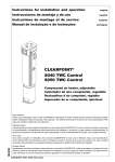
Parts & Features
See figures below for reference.
Air Intake Filter
Provides clean air to the pump and must always be kept free of debris. Check on a daily basis or before each use.
I
Indicates the outgoing air pressure to the tool and is controlled
Regulator Gauge
by the regulator.
Tank Pressure Gauge
Indicates the reserve air pressure in the tank.
Pressure Switch
This controlsthe power to the motor and also the
cut-in/cut-outpressure settings. This switch serves
as the Auto-On/Off positionsfor the unit,
Outlet Tube
Oil Fill Cap
Pressure Relief Valve
The pressure relief valve located on the
side of the pressure switch, is designed to
automatically release compressed air when
the air compressor reaches cut-out pressure.
The released air should only escape
momentarilyand the valve should then close.
J
Used to allow excess tank pressure to
escape into the atmosphere.This valve
should
Safety
onlyValve
open when the tank pressure 1
is above the maximum rated pressure.
Pressure
Relief Tube
Re_,.gulator
I ne air pressure coming from the air tank is
controlled by the regulator. To increase the
pressure turn the knob clockwise and to
decrease the pressure turn the knob
counterclockwise.
Quick
Offers
Connect
a quick release feature for attaching and removing the air hose. 1
Oil Sight Gauge
Tank Drain Valve
/
Used to drain condensation from the air tank, Located at bottom of tank.
I Check
WhenValve
the pump is not in operation the valve closes to retain air pressure inside the tank. An internal component. 1
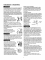
Installation
& Assembly
The air compressor should be turned off and unplugged from
the power source before any maintenance is performed as
well as the air bled from the tank and the unit allowed time
to cool. Personal injuries could occur from moving parts,
electrical sources, compressed air or hot surfaces. The
regulator assembly must be attached before use. Failure to
assemble correctly could result in leaks and possible injury.
If unsure of assembly instructions or you experience difficulty
in the assembly please call your local service department for
further instruction.
Quick Connect Assembly
1. Before assembly be sure that the
Quick Connect (Q.C.) threads have a
sealant applied from the factory to prevent
leaks around the threads. If no sealant is
present, wrap the threaded portion with
Teflon tape.
2. Attach the Q.C. assembly to the air compressor by
aligning the Q.C. threads to the regulator on the manifold.
Be certain to align the threads before tightening to prevent
thread damage.
3. The assembly should turn clockwise 1 to 1.5 revolutions
after hand-tightening with a 13/16ths size wrench. To prevent
damage and leaks, do not
over-tighten.
To Install the Air Intake Filter
Remove the air intake filter from the
poly bag and thread it onto the head
of the compressor as shown.
Do not attempt to start the air compressor without first adding
oil to the crankcase. Serious damage can result unless filled
with oil. The pump is shipped without oil from the factory.
Only use non-detergent oils since multi-viscosity motor oils
leave carbon deposits on pump components, thus reducing
performance and compressor life.
Drain the tank to release all tank air
pressure before removing the oil fill cap.
Be sure the air vent in the oil fill cap (see
figure to the right) is free from debris.
If air vent is blocked, pressure can build
in crankcase causing damage to the
compressor and possible personal injury.
_
Lubrication and Oil
Remove the oil fill cap by turning it
_
counter-clockwise by hand. Fill the
compressor pump with an air compressor
oil such as SAE-30 non-detergent (API
CG/CD Heavy Duty) oil at slow intervals
until the oil reaches the center of the red
circle in the sight glass ( see figure above).
Use SAE-10 during extreme winter conditions.
_.=t_{
'_L
Location of the Air Compressor
The air compressor should always be located in a clean,
dry, and well ventilated environment. The unit should have
at minimum, 12 inches of space on each side. The air filter
intake should be free of any debris or obstructions. Check
the air filter on a daily basis to be sure it is clean and in
working order.
Grounding instructions
This product should be grounded. In the event of an electrical
short circuit, grounding reduces the risk of electric shock by
providing an escape wire for the electric current. This product
is equipped with a cord having a grounding wire with an
appropriate grounding plug. (See the figure below.) The plug
must be plugged into an outlet that is properly installed and
grounded in accordance with all local codes and ordinances.
Check with a qualified
electrician or service
personnel if these
instructions are not
completely understood
or if in doubt as to
whether the tool is
properly grounded.
Outlet
Grounded
Grounding Pin
improper installation of the grounding plug will result in a
risk of electric shock. If repair or replacement of the cord
or plug is necessary, do not connect the grounding wire to
either flat blade terminal. The wire with insulation having an
outer surface that is green with or without yellow stripes is
the grounding wire. Check with a qualified electrician or
serviceman if the grounding instructions are not completely
understood, or if in doubt as to whether the product is
properly grounded. Do not modify the plug provided; if it
will not fit the outlet, have the proper outlet installed by a
qualified electrician.
This product is for use on a circuit having a nominal rating
of 120 volts and is factory-equipped with a specific electric
cord and plug to permit connection to a proper electric circuit.
Make sure that the product is connected to an outlet having
the same configuration as the plug. No adapter should be
used with this product. If the product must be reconnected
for use on a different type of electric circuit, qualified service
personnel should make the reconnection.
Extension Cords
/_-,,,
Use only a 3-wire extension cord that has a 3-blade
grounding plug, and a 3-slot receptacle that will accept the
plug on the product. Make sure your extension cord is in
good condition. When using an extension cord, be sure to
use one heavy enough to carry the current your product will
draw. Cords must not exceed 25 feet and No. 12 AWG size
must be used. An undersized cord will cause a drop in line
voltage resulting in loss of power and overheating.
Break In Procedures
No break in procedure is required by the user. This
product is factory tested to ensure proper operation and
performance.
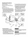
Operating Procedures
Daily Start-Up Procedures
(_)Set the Auto-On/Off lever to the Off position.
(_)oCrheCkthe air compressor visually for any damage
obstruction.
(_CIose
the drain valve.
(_)Check the oil level of the pump.
_tthonnect the air hose to the quick connect socket on
e regulator assembly by inserting the quick connect
plug on the air hose into the quick connect socket. The
quick connect socket collar will snap forward and lock
the plug into place providing an air tight seal between
the socket and plug. To release the air hose push the
collar back on the quick connect socket.
(_Plug
(_Turn the Auto-On/Off lever to the On-Auto position and
the compressor will start and build air pressure in the
tank to cut-out pressure and then shut off automatically.
(_)Adjust the regulator to a PSI setting that is needed for
your application and be sure it is within the safety
standards required to perform the task. If using a
pneumatic tool, the manufacturer should have
recommendations in the manual for that particular
tool on operating PSi settings.
Note: The air compressor is now ready for use. The
following inflation and cleaning accessories packaged
with this unit should only be operated at maximum
pressure of 20-30 PSI: blow gun, tapered nozzle,
inflation needles, blow gun adapter.
the power cord into the proper receptacle.
Dally Shut-Down Procedures
1. Set the Auto-On/Off lever to the Off position.
2. Unplug the power cord from the receptacle.
3. Set the outlet pressure to zero on the regulator.
4. Remove any air tools or accessories. When draining
the tank, always use ear and eye protection, Drain the
tank in a suitable location; condensation will be present
in most cases of draining.
5. Open the drain valve allowing air to bleed from the
tank. After all of the air has bled from the tank, close
the drain valve to prevent debris buildup in the valve,
When draining the tank, always use ear and eye protection.
Drain the tank in a suitable location; condensation will be
present in most cases of draining.
Water that remains in the tank during storage will corrode
and weaken the air tank which could cause the tank to
rupture. To avoid serious injury, be sure to drain the tank
after each use or daily.
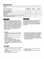
Maintenance
NOTE: Any service procedure not covered in the maintenance schedule below should be performed by qualified service
)ersonnel.
Before each
use or daily
Items to Check/Change
Check Tank Safety Valve
Overall Unit Visual Check
X
Check Oil Level
X
X
Check Air Filter (more frequently in dusty or humid environments)
X
Drain Tank (after each use or daily)
X
Oil Changing
For changing the pump 0il, be sure to do the following:
1. Turn the unit off and unplug the power cord from the
receptacle.
2. Allow the compressor time to cool if it has been in
operation.
3. Open the drain valve to bleed all air from the tank.
4. Close the drain valve.
5. Remove the oil fill cap on the pump.
6. Remove the sight glass with a box end wrench or
socket. Drain the oil into a suitable container and
dispose of properly. The compressor may need to be
tipped slightly towards the drain hole to allow all of the
oil to drain.
Every
100 hours
X
Change Oil
To ensure efficient operation and longer life of the air
compressor unit, a routine maintenance schedule should
be followed. The following schedule is geared toward a
consumer whose compressor is used in a normal working
environment on a daily basis. If necessary, the schedule
should be modified to suit the conditions under which your
compressor is used. The modifications will depend upon
the hours of operation and the working environment. Air
compressors used in an extremely dirty and/or hostile
environment will require a greater frequency of all
maintenance checks.
After first
10 hours
The air compressor should be turned off and unplugged
from the power source before any maintenance is
performed as well as the air bled from the tank and the
unit allowed time to cool. Personal injuries could occur
from moving parts, electrical sources, compressed air or
hot surfaces.
7. Reattach the sight glass. Note: Torque the sight glass
10-12 inch Ibs. when re-assembling. Be sure the gasket
is between the sight glass and the pump crankcase.
8. Refill the compressor pump with an air compressor oil
such as SAE-30 non-detergent (API CG/CD Heavy
Duty) oil at slow intervals until the oil reaches the center
of the red circle in the sight glass. Use a SAE-10 during
extreme winter conditions.
Storage
For storingthe air compressor, be sure to do the following:
1. Turn the unit off and unplug the power cord from the
receptacle.
2. Remove all air hoses, accessories, and air tools from
the air compressor.
3. Perform the daily maintenance schedule.
4. Open the drain valve to bleed all air from the tank.
5. Close the drain valve.
6. Store the air compressor in a clean and dry location.
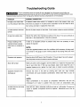
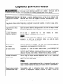
Troubleshooting Guide
The air compressor should be turned off and unplugged from the power source before any
maintenance is performed as well as the air bled from the tank and the unit allowed time to cool.
Personal injuries could occur from moving parts, electrical sources, compressed air, or hot surfaces.
PROBLEM
POSSIBLE CORRECTION
Air leaks at the check valve
A defective check valve results in a constant air leak at the pressure relief valve
or at the pressure relief valve,
when there is pressure in the tank and the compressor is shut off. Drain the tank,
then remove and clean or replace the check valve.
Air leaks between head and
Be sure of proper torque on head bolts. If leak remains, contact a service technician.
cylinder.
Air leak from safety valve.
Operate the safety valve manually by pulling on the ring. If the valve continues to
leak when in the closed position,it should be replaced.
Pressure reading on the
If there is an excessive amount of pressure drop when the accessory is used,
regulated pressure gauge
replace the regulator.
drops when an accessory is
used.
NOTE:
Adjust the regulated pressure under flow conditions(while accessory is being used),
It is normal for the gauge to show minimal pressure loss during initial use of the
tool.
Excessive tank pressure.
Move the Auto-On/Off lever to the Off position. If the unit doesn't shut off, unplug it
from the power source and contact a service technician.
Motor will not start.
Make sure power cord is plugged in and the switch is on. Inspect for the proper size
fuse in your circuit box. If the fuse was tripped, reset it and restart the unit. If
repeated tripping occurs, replace the check valve or contact a service technician.
Excessive moisture in the
Remove
discharge air.
environments will cause excessive condensation. Utilize water filters on your air
the water in the tank by draining
after each use. High humidity
line.
NOTE:
Water condensation is not caused by compressor malfunction. Be sure the
compressor's air
Air leaks from the tank body
or tank welds.
output is greater than your tool's air
consumption rate.
Never drill into, weld or otherwise modify the air tank or it will weaken. The tank can
rupture or explode. Compressor cannot be repaired.
compressor.
Discontinue use of the air
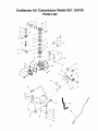
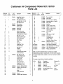
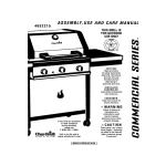
Craftsman Air Compressor Model 921.153100
Parts List
,_
i
32
_j33
20J
_j3,
! ._"_
I
35
F
I
/
31
I
51
50
5
/
52
53
8
Craftsman Air Compressor Model 921.153100
Parts List
Reference Kit
Number Number
Part
Number
Description
IntakeFilterHousing,
1/2NPT(Kunsan)
FilterElement(Kunsan)
HeadBolt,M8x 1.0x 30
1
LockWasher,6mm
E100594 StrainRelief
E100205 PressureGuage,2" 200PSI
8
44
45
E100093 PressureGuage,1.5"200PSI
E100094 SafetyValve
E100227 CylinderHead
E100085 ExhaustElbow
1
1
46
47
E100059 Regulator
E100091 Coupler,QuickConnect
Gasket,Head
E100228 ValvePlate
1
2
48
49
E100595 Nipple,1/4"NPTx 27ram
E100598 Nipple,1/4"NPTx 80mm
1
1
E100229 ValveReed
2
1
E100435
10
11
12
13
14
Quantity
48
2
3
8
9
Description
42
EI00434
2
Part
Number
E100957 PressureSwitch
1
6
7
:_eference Kit
Number Number
41
1
4
5
Quantity
2
2
3
2
1
4
1
2
1
1
1
1
1
Gasket,ValvePlate
Gasket,CylinderUpper
1
1
50
51
52
OutletTubeAssy
E100097 Grip,Handle
Tank
1
1
1
Cylinder,ID42mmx H65mm
Bolt,M6x 1.0x 20
1
5
53
54
E100098 DrainValve,1/4"NPT
E100099 CheckValve
1
1
Gasket,CylinderLower
Ring,Compression
1
2
55
56
6
6
6
15
16
17
18
3
3
3
3
Ring,Scraper
Piston
1
1
57
58
PistonPin
1
59
19
20
3
3
21
22
23
3
3
4
SnapRing,12mm
RodConnecting
Nut,M6x 1.0
Eccentric
2
1
1
1
24
25
4
Oil Fill Cap
O Ring,OD17mmx 2mm
Cover,Crankcase
E100235 Bolt,M5x0.8 x 15
1
1
1
10
FlatWasher,8ram
Isolator,Rubber
16
4
Bolt,M8x 1.25mmx 20mm
E100101 PowerCord14/3x 6'
4
1
Bolt,M8x 1.25ramx 25ram
4
Not Shown
Not Shown
E100110 Label,DrainTankWarning
1
E100370 Label,SpecificationHP,Tanksize 1
Not Shown
Not Shown
E100859 Label,WarningBilingualTank
E100731 Manual,Operators/Parts
1
1
Note:AnypartJkltnumberfieldwithout
a numberisnotavailable.
26
27
5
Seal,Oil SightGauge
1
Descriptionsareprovidedfor referenceonly. TheKit# columnrepresents
thatthe partbeingofferedis availablein a kit. Oneof eachpartper kitwill
be offered.
28
29
5
2
Oil SightGauge
RubberBaffle
1
I
Kitnumberandpartsthatare includedare asfollows:
3O
31
6
Nut,M8x 1.25
Washer,Flat8ram
10
2
Screw,M3x 0.5x 6
4
SpringWasher,3ram
Capacitor,Starting(200pF)
Capacitor,RunningHOpF)
CrankCase
4
1
1
1
Motor
1
32
33
34
35
36
37
38
39
40
E100248
E100247
Cover,MotorRear
E100955 Shroud
E100956 PressureReliefTubeAssy
1
1
1
KitNo.
1
2
PartNo.
E100434
E100959
Description
IntakeFilterKit
GasketKit
ReferenceNo.
1,2
7, 10-11,14,29
3
E100251
PistonKit
13,15-22
4
5
6
E100087
E100088
E100102
Oil FillCapw/O-ring
23-24
Oil SightGaugew/O-ring 27-28
IsolatorKit
30,55-57
CONTENIDO
P.Sgina
Garantfa
...............................................
esta p&gina
Instrucciones de seguridad .........................................
11
Instrucciones y pautas de seguridad importantes
11
Especificaciones
........................
................................................
12
GIosario .......................................................
12
Ciclo de trabajo
12
.................................................
Partes y caractedsticas
Instalaci6n y ensamblaje
...........................................
13
..........................................
14
Procedimientos de operaci6n .......................................
15
Mantenimiento ..................................................
16
Almacenamiento
16
................................................
Diagn6stico y correcci6n de fa_las ...................................
17
Lista de partes ..................................................
GARANT|A
8
DE UN AI_IO SOBRE COMPRESOR
DE AIRE CRAFTSMAN
Si este compresor de aire Craftsman llega a fallar debido a defectos de manufactura o de
matedales atribuibles al fabricante en un plazo de un aSo desde la fecha de compra, DEVUI_LVALO
A LA TIENDA O CENTRO DE SERVICIO SEARS M/_S CERCANO EN LOS ESTADOS UNIDOS
para que le sea reemplazado o reparado (a opci6n nuestra) sin ning_n cargo.
Si este compresor de aire se usa con fines comerciales o de renta, esta garantfa L_nicamente
aplica por 90 (noventa) dfas a partir de la fecha de compra. Esta garantia le da derechos legales
especfficos; adem&s, es posible que usted tenga otros derechos, los cuales varfan segL_n el
estado.
Sears, Roebuck and Co., Dept. 817WA,
Hoffman Estates, IL 60179
10
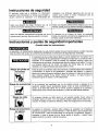
Instrucciones de seguridad
compresor. Los sfmbolos siguientes son los qua se
utilizan para indicar al lector informacion qua es
importante para su seguridad.
El operador debe leer y entender la informaci6n
siguiente. Esta informaci6n se ofrece para proteger al
usuario durante la operaci6n y el almacenaje del
Indica una situaci6n de riesgo inminente que, de no
evitarse, provocarfa lesiones graves o la muerte.
Indica una situaci6n potencialmente peligrosa que, de no
evitarse, podffa provocar lesiones menores o modaradas.
Indica una situaci6n potencialmente peligrosa qua, de no
evitarse, podrfa provocar lesiones graves o la muerte.
AI aparecer sin el sfmbolo de alerta de seguridad,
indica una situaci6n potencialmente peligrosa qua, de no
evitarse, podrfa causar dafios materiales.
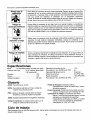
Instrucciones y pautas de seguridad importantes
• Guarde todas las instrucciones,
La operaci6n y el mantenimiento inadecuados de este producto pueden provocar lesiones graves y dafios materiales.
Antes de utilizar este equipo, lea y entienda las advertencias e instrucciones de seguridad aquf contanidas.
El compresor de aire se debe operar desde un circuito dedicado de 15 amperes. Si el
circuito no dispone de una capacidad de 15 amperes, se debe usar un circuito de mayor
capacidad. Si es necasario, antes de emplear una extensi6n el6ctrica, afiada una
manguera de aire m_.s larga. Las extensiones el6ctricas deben ser de calibre 12 y tener
una Iongitud m_.xima de 7.6 metros. El fusible del circuito debe set de acci6n
retardada. Un voltaje demasiado bajo pueda dafiar el motor.
Riesgo por partes en
movimiento
Antes de operar el compresor, todos los protectores y cubiertas deben estar instalados
correctamenta. Si alguno de los protectores o cubiertas est& dafiado, no opera el
equipo sino hasta que personal calificado repare el problema. El cable de corriente se
debe mantener alejado de las partes m6viles del equipo y no debe torcerse ni
prensarse durante su empleo ni al set almacenado.
Riesgo de quemaduras
En su compresor hay superficies que, de ser tocadas clurante y despu6s de su
operaci6n, pueden causar quemaduras graves. Antes de darle mantenimiento al
equipo, sele debe dejar enfriar. Por Io normal, durante y despu6s de su operaci6n,
ciertas partes como la bomba del compresor y el tubo de salida estaran calientes.
i
Riesgo de cafda
El compresor siempre se debe operar en una posici6n estable. Nunca utilice el
comprasor sobre un techo o en una posici6n elevada desde donde podrfa caer o
volcarse. AI trabajar en posiciones elevadas, utilice una manguera de aire mas larga.
Riesgo de lanzamiento
de objetos
AI emplear el compresor, siempre utilice anteojos de seguridad con protectores
laterales que cumplan con la norma ANSI Z87.1. Antes de Ilevar a cabo cualquier clase
de mantenimiento y antes de desconectar las mangueras y acopladores, apague el
compresor y drene el tanque de aire. Nunca apunte la boquilla o rociador hacia
ninguna parte de su cuerpo ni del de otros seres.
11
Instrucciones y pautas de seguridad irnportantes (cont,)
Riesgo para la
respiraci6n
Evite utilizar el compresor de aire en _reas encerradas. Siempre tenga un espacio libre
adecuado (30 cm.) en todos los lados del compresor.Tambi6n mantenga fuera del drea
do operaci6n a mascotas, ni6os y otras personas. Este compresor de aire no provee
aire que pueda ser respirado ni empleado con un dispositivo respiratorio
auxiliar. El materialde rociadosiempre debera, estar en otra zona, alejado del compresor
de aire, para evitar que el aire aspirado daSe el filtro del compresor.
Riesgo de
descargas el_ctricas
Nunca utilice el compresor de aire bajo Iluvia o en lugares mojados. Los problemas
el_ctricos deben ser reparados por personal autorizado, tal como serfa un electricista,
y deben cumplir con las normas electricas nacionales y locales. El compresor tambi_n
debe toner la clavija apropiada de tres terminales y contar con un suministro el_ctrico
que sea del voltaje correcto y con un fusible de protecci6n adecuado.
Rlesgo de
explosi6n y fuego
Nunca opere el compresor cerca de materiales combustibles, gasolina ni vapores de
solventes. Si est_l rociando materiales inflamables, coloque el compresor a una
distancia de cuando menos 6 metros del _.rea de rociado. Nunca opere el compresor
de aire en interiores o on lugares cerrados.
Riesgo de estallido
Drene el compresor diariamente o despuds de cada utilizaci6n. Si el tanque tiene una
fuga, reemplace el compresor. No utilice el compresor si se ha detectado una fuga, ni
trate de modificar el tanque. Nunca modifique los ajustes de f_.brica del compresor que
._ _1 _l_ '
controlan la pres,6n del tanque y dem,s funciones.
Especificaciones
Bomb .....
De impulsi6n directa, lubricada con aceite
Inducci6n del motor.. :...1.5 HP mdximo desarrollado,
1 HP funcionando
Di_.metro ..........................
1.65"
Carrera ...........................
1.26"
Voltaje monofasico ..................
120 VAC
Capacidad mfnima del circuito .........
15 A
Pies cL_bicosx min. (SCFM) a 90 LPPC .. 2.4
Capacidad del tanque de aire ..........
3 galones
Presi6n de arranque .................
95 LPPC (PSI)
Presi6n de parada ..................
125 LPPC (PSI)
Pies cL_bicosx min. (SCFM) a 90 LPPC .. 2.4
Glosario
Presi6n de arranque: El compresor arranca
autorndticamente cuando la presi6n baja a menos
del mfnimo prescrito.
Presi6n de parada: Presibn de aire que tiene que alcanzarse en el tanque para que se detenga el motor.
Certificaci6n de c6digo: Los productos que tienen
alguna o varias de las siguientes marcas han sido
evaluados por laboratorios de seguridad
independientes certificados por OSHA, y cumplen
con las normas de seguridad de Underwriters
Laboratories: UL, CUL, ETL, CSA.
aCFM: Pies cdbicos per minute.
SCFM: Pies c_bicos estdndar per minuto; unidad de
medici6n do suministro de aire.
PSIG: Libras por pulgada cuadrada sobre la presi6n
atmosfdrica; unidad de medici6n de presi6n.
ASME: Sociedad estadounidense de ingenieros mecanicos.
C6digo de California: La unidad puede cumplir con el
c6digo de California 462 (1)(2)/(M) (2).
Ciclo de trabajo
Este compresor tiene un ciclo de trabajo de 50%. Nunca opere el compresor por m_s de 30 minutos cada hora. De
hacerlo, podrfa daSarlo.
12
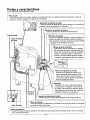
Partes y caracterfsticas
Como referencia, yea las figuras de abajo.
Filtro de aire
Suministra aire Iimpio a la bomba. Siempre se le debe tenet libre de suciedad. Revfselo diariamente o antes de
cada uso. (V_ase la imagon en la secciSn do ensamblaje.
!
Indica la presion de salida del aire que se entrega a la herramienta
presiSn que es contrelada por el regulador.
t
Mandmetro de presidn del tanque
Indica la presi6n de la reserva de aire del tanque.
Tubo de salida
Interruptor de presi6n
Controla el suministro el_ctrico al motor y tambi_n los[
ajustes de presi6n de arranque y presi6n de parada. |
Este interruptor sirve como posici6nde autoencendidoI
Tap6n de Ilenado
de aceite
y apagado (Auto-On/On de la unidad.
J
Vdlvula de alivio de presi6n
Esta v_.lvula, que se encuentra en el costado
del interruptorde presi6n, esta disefiada para
Iiberar aire comprimidode manera automdtica
cuando el compresor Ilegue a la presi6n de
parada. El aire s61odeber_, escapar durante
un instante, cerr_.ndosela v&lvula en seguida.
de seguridad del tanque
Permite que el excese de presibn en el
tanque escape al medio ambiente. Esta
v_.lvula s61ose abrir_ cuando la presi6n
en el tanque este por encima de la presi6n
mdxima nominal del modelo.
Regulador
La presiSndel aire que sale del tanque es
controlada pot el regulador. Para aumentar
la presi6n, gire la perilla en direcci6n de las
manecillas; para disminuida, gire Laperilla en
direcci6n contraria alas maneoillas.
Vdlvula de
retenci6n
Conector de acoplamiento rdpido
Permite conectar y desconectar r_pidamente ]a manguera de aire.
Visor de aceite
J
Sirve para drenar la condensaci6n acumulada en
el fonde del tanque. Se encuentra1
I Vdfvula
de drenado
en la parte
inferior del tanque.
V=_lvulade retenci6n
Cuande la bomba no est,. en operaciSn, esta v_.lvulase cierra para retener la presi6n de aire dentro del tanque.
Es un cemponente interne.
13
J
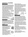
Instalacibn y ensamblaje
Ubicacl6n del compresor de aire
El compresor de sire siempre debe estar en un medio ambiente
limpio, seco y bien ventilado. La unidad debe tener cuando
menos 30 cm, de espacio libre en carla lado. La toms del filtro
de sire debe estar libre de suciedad y obstrucoiones. Por favor
revise diadamente el filtro de aire pars comprobar que est_
limpio yen correcto estado de funcionamiento.
Antes de dar mantenirniento al compresor de aire, se le debe
apagar y desconectar de la fuente de poder, adem_s de purgar
el aire del tanque y dade suficiente tiempo pars enfriarse, Existe
el desgo de que las partes m6viles, ]a fuente el_ctrica, el sire
comprimido y las superficies calientes provoquen lesiones. El
ensamble del regulador debe estar instalado antes de usar el
cornpresor. Un ensamblaje inadecuado puede set causa de
fugas y posiblemente de lesiones. Si no entiende las instrucclones de ensamblaje o tiene dificultad pars Ilevar a cabo el
armado, por favor Ilame a su departamento IocaJde servicio.
Conjunto de conexi6n r_pida
1. Antes de ensamblar, compruebe que
Instrucciones de conexibn a tierra
Este producto se debe conectar a tierra. En caso de
cortocircuito, la conexibn a tierra reduceel desgo de descargas
el_ctricosal ofrecer un alambre de escape para la cordente
el_etdca. Este producto cuenta con un cable que tiene un alarnbre
de tierra y una clavijacon terminal de tierra. La clavija debe
enchufarseen un tomacordenteinstaladoy puestoa tJerrasegL_n
las normas locales, Hable con un eleclricistao agente de servicio
calificadosi no entiende
completamenteestas
Plug
instrucciones, o si tiene
J'_-.-_i _%_-_-__ Grounded
_._|'\/
,_ i _ _
se haya aplicado de fabrica un sellador
..,.-=_ _c_ ,T-_i,,
a la rosca del conector r_pido, con el fin
_J_o_,
._ •
de evitar fugas por esa zona. Si no hay
sellador, enrolle la parte roscada con einta de tefldn.
2. Cone_e el conjunto de conexi6n rdpida al eompresor de
sire, alineando la rosca del conector r_.pido con el regulador
en el colector. Para evitar dados alas roscas, aseg0rese de
alinearlas eorrectamente antes de roscarlas.
dudas
la de
correcta
puesta sobre
a tierra
la herramienta.
3. El conjunto se debe apretar a mano en direcci6n horaria
y luego apretar de 1 a 1.5 vueltas con una Ilave de 13/16".
Para evitar da_ios y fugas, no apriete demasiado.
Instalaci6n del filtro de aire
Saque el filtro de aire de entrada de la
bolsa de poliuretano y enr6squela en el
cabezal de la compresora, come se rnuestra.
/_._.
_
Este producto est_ disedado para trabajar en un cireuito con
un voltaje nominal de 120 volts y est_ dotado de fdbrica con un
cable y clavija que permiten su conexi6n aun circuito eldctfico
apropiado. AsegLirese de que el producto est_ conectado aun
tomacordente con la mnismaconfiguraci6n que la clavija. No se
debe usar un adaptador con este equipo. Si se debe conectar el
equipo aun circuito el_ctrico de diferente tipo, consiga la ayuda
de personal calificado.
Antes de quitar el tap6n de Ilenado de aceite,
Extensiones eldctricas
$61o utilice una extensidn el_ctrica de tres alambres con
una clavija aternzada de tres terminales que pueda enchufarse
en un tomacorriente de tres orificios.AsegL_rese de que su
extensi6n el6ctrica est_ en buenas condiciones. Si utiliza una
extensi6n, compruebe que sea de la capacidad de eordente que
requiere su equipo. Las product is factory tested to ensure proper operation and performance.
L_Z.j_ 'i,L
Lubricaci6n y sceite
Quite el tapdn de Ilenado de aceite girdndolo %.
con la mano en direcci6n contraria alas
manecillas. Llene ]entamente la bomba del
. _\\
compresor con aceite para compresor de sire, "{(f(_O
como aceite SAE-30 no detergente (API
._._//'_..I
CG/CD de trabajo pesado) basts que Ilegue al
centro del c[rculo rojo del visor, como se
muestra en la imagen. En condiciones extrernas
de invierno use aceite SAE-10.
Outlet
Una conexibn a tierra inadecuada puede provocar una
descarga el_ctrica. Si necesita reparar o cambiar el cable
o la clavija, no conecte el alambre de tierra a ninguna de las
terminales planas. El a[ambre de tierra es el de color verde,
con o sin franjas amarillas. Si no entiende completamente las
instrucciones de conexi6n a tierra, o si tiene dudas sobre la
corrects puesta a tierra de Is herramienta, hable con un electricista
o agente de servicio calificado. No modifique la clavija que viene
con el equipo;si no puede enchufarla en el tomacordente, Ilame
aun electdcista para que cambie el tomacorriente.
sin antes
adadir aceite al dep6sito. De no flenado de aceite y seguir el
procedimiento de operaci6n, el compresor podria sufrir da_os
graves. La bomba sale de la fdbrica sin aceite. En el depbsito
queda una pequeFla cantidad de aceite, sobrante de las pruebas en la fdbrica, $61o use aceite no detergente, pues los
aceites mulfigrado para motor dejan dep6sitos de carb6n en tos
componentes de la bomba, reduciendo el desempefio y la vida
del compresor.
drene el tanque para liberar la presi6n de aire._
Compruebe que el respiradero del tapbn de 'i_
Ilenado de aceite est_ limpio (veala
ilustraci6n). Si est_ bloqueado, puede haber
una acumulaci6n de presibn en el dep6sito,
dadando el compresor y posiblemente
causando lesiones al operador.
_1_--_"
./
GroundingPin L_=_' I
Procedimiento inicial de preparacibn
No se requiere un procedimiento inicialde preparacibn.
Este producto ha sido probado an la f_.brica para asegurar su
operaci6n y desempedo adecuados.
"}'_/Y"
14
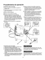
Procedimientos de operaci6n
Procedimiento diario de arranque
(_Ponga el interruptor Auto-On/Often
apagado (Off).
_Compruebe
visualmente qua
dafios ni obstrucciones.
el
la posici6n de
compresor no tenga
(_)Cierre la v&lvula de drenado.
(_Revise
el nivel de aceite de la bomba.
Enchufe la manguera de aire al conector de
acoplamiento rdpido de la unidad del regulador. El
collarin del conector de acoplamiento r#.pido saltar_,
para adelante, sujetando el enchufe y efectuando un
sello entre el conector y el enchufe. Para desconectar
la manguera de aire, empuje hacia atrds el collarfn del
conector de acoplamiento rdpido.
@Mueva el interruptor Auto-OniOffa la posici6n de
encendido (Auto-On); el compresor deberd arrancar,
acumulando presi6n de aire en el tanque hasta Ilegar
a la presi6n de apagado, momento en el cual se
apagard de manera automdtica.
(_)Ajuste el regulador a la presi6n de aire recomendada
para su aplicaci6n, cercior_.ndose de que est_ dentro
de las normas de segufidad para Ilevar a cabo la
tarea. En el caso de herramientas neum&ticas, el
manual del fabricante debe tener recomendaciones
sobre su presi6n de operaci6n.
Nora: Ahora el compresor de aire est,. listo para ser
usado. Los siguientes accesorios de inflado y limpieza,
los cuales vienen con esta unidad, solo se deben
operar a una presi6n mdxima de 20-30 PSI: soplete
(y su adaptador), boquilla c6nica, agujas de inflado.
(_Enchufe el cable de corriente en un tomacorriente
apropiado.
Procedimiento diario de apagado
1. Ponga el interrupter en la posici6n de apagado (Of/).
2. Desconecte el cable del tomacorriente.
3. Ponga en cero el regulador de presi6n de salida.
4. Desconecte las herramientas y accesofios. Siempre
use protecci6n para ofdos y ojos al drenar el tanque.
Drene el tanque en un lugar adecuado; en casi todos
los casos habra, presencia de condensaci6n en el
drenaje.
5. Abra la vdlvula de drenado permitiendo que escape el
aire del tanque. Cuando haya salido del tanque todo el
aire, cierre la v_.lvula de drenado para evitar que le
entre suciedad.
AI drenar el tanque utilice protecci6n para ofdos y ojos.
Drene el tanque en un lugar apropiado; en la mayorfa de
Lasocasiones al drenar saldr& condensaci6n.
Si no drena el tanque, en su interior quedar_, agua que Io
corroer_ y debilitar_., Io cual puede provocar su ruptura.
Siempre drene el tanque diariamente o despu_s de cada
use.
15
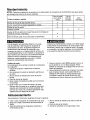
Mantenimiento
NOTA: Cualquier procedimiento de servicio que no este cubierto en el prograrna de mantenimiento que sigue deberd
ser efectuado por personal de servicio calificado.
Antes de cada
uso o diariamente
Puntos a revisar o ¢ambiar
Revisar la va.lvula de seguridad del tanque
X
Reviser visualmente el aspecto general de la unidad
X
Revisar el nivel de aceite
X
Cambiar el aceite
Revisar el filtro de aceite (con mayor frecuencia si se trabaja en
ambientes polvosos o hSmedos)
X
Drene el tanque (cada vez que sea usado o diariamente)
X
Tras las
primeras
10 horas
Cada
100 horas
X
X
A fin de asegurar una operaciSn eficiente y una larga
vida del compresor, debe seguirse un programa de
mantenimiento de rutina. El siguiente programa de
mantenimiento est,. enfocado al consumidor cuyo
compresor es usado en un medio ambiente normal y con
una periodicidad diaria. De ser necesario, el programa se
debe modificar pare adecuarlo alas condiciones bajo las
cuales se usar_, su compresor. Los compresores em
pleados en medios ambientes muy sucios u hostiles
requerir_.n mantenimiento m_.sfrecuente.
Antes de dar mantenimiento al equipo, se le debe apagar
y desconectar del tomacorriente, asf como purger el aire
del tanque y permitir que la unidad se enfrfe. Las partes
en movimiento, las fuentes electricas, el aire comprimido
y las superficies calientes pueden provocar lesiones.
Cambio de aceite
El procedimiento pare cambiar el aceite de la compresora
es el siguiente:
1. Apague el eompresor y desenchufe el cable de
corriente.
2. Si el eompresor ha estado en operaci6n, permita que
se enfrie.
3. Abra la v&lvula de drenado para vaciar el aire del
tanque.
4. Cierre la v&lvula de drenado.
5. Quite el tapSn de [lenado de aceite que se eneuentra
on la bomba.
6. Quite el visor con una Ilave de tuercas o de cubo.
Deje que drene el aeeite on un recipiente adecuado y
deseche este contenedor de manera apropiada. Tel
vez haya que incliner el compresor ligeramente hacia
adelante para que salga todo el aceite.
7. Vuelva a colocar el visor. NOTA: apriete el visor a un
par do apriete de 10 a 12 libras-pulgacla. Revise
tambi_n le colocacion del empaque entre el visor y el
c_,rter del compresor.
8. Llene lentamente la bomba del compresor con aceite
pare compresor de aire, como aceite SAE-30 no
detergente (API CG/CD de trabajo pesado) hasta
que Ilegue al centro del c(rculo rojo del visor. En
condiciones de invierno extremas use aceite SAE-10.
Almacenamiento
Pare almacenar el compresor, asegL_resede hacer Io siguiente:
4. Abra la v_Jvula de drenado para drenar el aire del
tanque.
5. Cierre la v_.lvula de drenado.
6. Guarde el compresor en un lugar limpio y seco.
1. Lleve a cabo el programa de mantenimiento de rutina.
2. Apague la unidad y desconecte del tomacorriente la
clavija.
3. Quite de1compresor las mangueras, accesorios y
herramientas de aire.
16
Diagnbstico y correccibn de fallas
Antes de dar mantenimiento al equipo, se le debe apagar y desconectar del tomacorriente,
asi come purgar el aire del tanque y permitir que la unidad se enfr{e. Las partes en
movimiento, las fuentes el6ctricas, el aire comprLmido y las superficies ca[ientes pueden provoear lesiones.
PROBLEMA
POSIBLE CORRECCION
Fuga de aire en ta valvula do
retenci6n o en la v_.lvu]a de
Una v_.lvula de retenci6n defectuosa provoea una fuga de aire constante en la
v_lvula de alivio cuando est_ apagado el compresor teniendo presi6n de aire.
alivio.
Drene el tanque y quite y limpie o cambie ]a valvula de retenci6n.
Fugas de aire entre la cabeza
Compruebe el apriete de los pernos de la cabeza. Si contin=]a la fuga, Ilame a
y el cilindro,
un t6cnico de servicio.
Fuga de aire en la va.lvula
Opere manualmente la v_.lvula do seguridad tirando del anillo. Si el tanque contin6a
de seguridad,
teniendo una fuga estando la v_.lvula en posici6n cerrada, 6sta deber_, ser cambiada.
La presi6n indicada en el
Si
man6metro de preei6n
cambie el regulador, regulada cae al usar un accesodo.
al
usar
un
accesorio
hay
una
ca[da
excesiva
de
presion,
Ajuste la presi6n regulada bajo condiciones
de flujo (mientras se utiliza un
accesorio).
Es normal que el man6metro
minima al comenzar a utilizar la herramienta.
indique
una caida
de presi6n
Presi6n excesiva
Apague el interruptor de encendido. Si la unidad no se apaga, descon_ctela del
on el tanque,
tomacorriente y comun[quese con un tecnico de servicio.
El motor no arranca.
Compruebe que el cable de corriente esta enchufado y que el interruptor est&
encendido. Compruebe que el fusible de la caja de circuitos sea de la capacidad
adecuada. Si se ha disparado, restabl6zcalo y rearranque la unidad. Si el fusible so
dispara con frecuencia, revise la vaivula de retenci6n o Ilame a un t_cnico de servicio.
Humedad excesiva en el
aire de salida.
Saque el agua del tanque dren_.ndolo despu6s de cada vez que se use. En los
medios ambientes de alta humedad habr_, un exceso de condensaci6n; instale
filtros de agua en su I_nea de aire.
La condensaci6n no es provocada pot una falla en el compresor. Compruebe que la
salida de aire del compresor sea mayor que el consumo de aire de su herramienta.
Fugas do aire en el cuerpo
Nunca taladre,
suelde o modifique de ninguna manera el tanque, pues se
o la soldadura del tanque.
debilitar_.. El tanque
podria
romperse o explotar.
reparado. Ya no utilice el eompresor de aire.
17
El tanque
no puede ser
Your Home
For repair - in your home - of all major brand appliances,
lawn and garden equipment, or heating and cooling systems,
no matter who made it, no matter who sold it!
For the replacement parts, accessories and
owner's manuals that you need to do-it-yourself.
For Sears professional installation of home appliances
and items like garage door openers and water heaters.
1-800-4-MY-HOME
® (1-800-469-4663)
Call anytime, clay or night (U.S.A. and Canada)
www.sears.com
www.sears.ca
Our Home
For repair of carry-in items like vacuums, lawn equipment,
and electronics, call or go on-line for the location of your nearest
Sears Parts & Repair Center.
1-800-488-1222
Call anytime, day or night (U.S.A. only)
www,sears.com
To purchase a protection
1-800-827-6655
agreement
on a product serviced by Sears:
(U.S.A.)
1-800-361-6665
(Canada)
Au Canada pour service en fran_ais:
Para pedir servicio de reparaci6n
a domicilio, y para ordenar piezas:
1-800-LE-FOYER M°
1-888-SU-HOGAR s"
(1-800-553-6937)
www.sears.ca
(1-888-784-6427)
SEARS
® Registered
® Marca
Marque
Trademark/TM
Registradei
de commerce/
Trademark/`"
Marca
de F_b_cei
Marque
ddposde
Service
Marca
Mark
of Sears,
de Servicio
de Sears,
Roebuck
Roebuck
de Sears,
and Co.
_md Co.
Roebuck
and Co.
© Sears,
Roebuck
and Co.