1
DES-7000 Series
Layer 2 Switch
Command Line Interface
Reference Manual
First Edition (February 2003)
6ES7000CLI01
Printed In Taiwan
RECYCLABLE
Wichtige Sicherheitshinweise
1.
Bitte lesen Sie sich diese Hinweise sorgfä ltig durch.
2.
Heben Sie diese Anleitung für den spä tern Gebrauch auf.
3.
Vor jedem Reinigen ist das Gerä t vom Stromnetz zu trennen. Vervenden Sie keine
Flüssig- oder Aerosolreiniger. Am besten dient ein angefeuchtetes Tuch zur Reinigung.
4.
Um eine Beschä digung des Gerä tes zu vermeiden sollten Sie nur Zubehörteile
verwenden, die vom Hersteller zugelassen sind.
5.
Das Gerä t is vor Feuchtigkeit zu schützen.
6.
Bei der Aufstellung des Gerä tes ist auf sichern Stand zu achten. Ein Kippen oder
Fallen könnte Verletzungen hervorrufen. Verwenden Sie nur sichere Standorte und
beachten Sie die Aufstellhinweise des Herstellers.
7.
Die Belüftungsöffnungen dienen zur Luftzirkulation die das Gerä t vor Ü berhitzung
schützt. Sorgen Sie dafür, daß diese Ö ffnungen nicht abgedeckt werden.
8.
Beachten Sie beim Anschluß an das Stromnetz die Anschluß werte.
9.
Die Netzanschluß steckdose muß aus Gründen der elektrischen Sicherheit einen
Schutzleiterkontakt haben.
10. Verlegen Sie die Netzanschluß leitung so, daß niemand darüber fallen kann. Es sollete
auch nichts auf der Leitung abgestellt werden.
11. Alle Hinweise und Warnungen die sich am Gerä ten befinden sind zu beachten.
12. Wird das Gerä t über einen lä ngeren Zeitraum nicht benutzt, sollten Sie es vom
Stromnetz trennen. Somit wird im Falle einer Ü berspannung eine Beschä digung
vermieden.
13. Durch die Lüftungsöffnungen dürfen niemals Gegenstä nde oder Flüssigkeiten in das
Gerä t gelangen. Dies könnte einen Brand bzw. Elektrischen Schlag auslösen.
14. Ö ffnen Sie niemals das Gerä t. Das Gerä t darf aus Gründen der elektrischen Sicherheit
nur von authorisiertem Servicepersonal geöffnet werden.
15. Wenn folgende Situationen auftreten ist das Gerä t vom Stromnetz zu trennen und von
einer qualifizierten Servicestelle zu überprüfen:
a – Netzkabel oder Netzstecker sint beschä digt.
b – Flüssigkeit ist in das Gerä t eingedrungen.
c – Das Gerä t war Feuchtigkeit ausgesetzt.
d – Wenn das Gerä t nicht der Bedienungsanleitung ensprechend funktioniert oder Sie
mit Hilfe dieser Anleitung keine Verbesserung erzielen.
e – Das Gerä t ist gefallen und/oder das Gehä use ist beschä digt.
f–
Wenn das Gerä t deutliche Anzeichen eines Defektes aufweist.
16. Bei Reparaturen dürfen nur Orginalersatzteile bzw. den Orginalteilen entsprechende
Teile verwendet werden. Der Einsatz von ungeeigneten Ersatzteilen kann eine weitere
Beschä digung hervorrufen.
17. Wenden Sie sich mit allen Fragen die Service und Repartur betreffen an Ihren
Servicepartner. Somit stellen Sie die Betriebssicherheit des Gerä tes sicher.
18. Zum Netzanschluß dieses Gerä tes ist eine geprüfte Leitung zu verwenden, Für einen
Nennstrom bis 6A und einem Gerä tegewicht grő ß er 3kg ist eine Leitung nicht leichter
als H05VV-F, 3G, 0.75mm2 einzusetzen.
ii
WARRANTIES EXCLUSIVE
IF THE D-LINK PRODUCT DOES NOT OPERATE AS WARRANTED ABOVE, THE
CUSTOMER'S SOLE REMEDY SHALL BE, AT D-LINK'S OPTION, REPAIR OR
REPLACEMENT. THE FOREGOING WARRANTIES AND REMEDIES ARE EXCLUSIVE AND
ARE IN LIEU OF ALL OTHER WARRANTIES, EXPRESSED OR IMPLIED, EITHER IN FACT
OR BY OPERATION OF LAW, STATUTORY OR OTHERWISE, INCLUDING WARRANTIES OF
MERCHANTABILITY AND FITNESS FOR A PARTICULAR PURPOSE. D-LINK NEITHER
ASSUMES NOR AUTHORIZES ANY OTHER PERSON TO ASSUME FOR IT ANY OTHER
LIABILITY IN CONNECTION WITH THE SALE, INSTALLATION MAINTENANCE OR USE OF
D-LINK'S PRODUCTS
D-LINK SHALL NOT BE LIABLE UNDER THIS WARRANTY IF ITS TESTING AND
EXAMINATION DISCLOSE THAT THE ALLEGED DEFECT IN THE PRODUCT DOES NOT
EXIST OR WAS CAUSED BY THE CUSTOMER'S OR ANY THIRD PERSON'S MISUSE,
NEGLECT, IMPROPER INSTALLATION OR TESTING, UNAUTHORIZED ATTEMPTS TO
REPAIR, OR ANY OTHER CAUSE BEYOND THE RANGE OF THE INTENDED USE, OR BY
ACCIDENT, FIRE, LIGHTNING OR OTHER HAZARD.
LIMITATION OF LIABILITY
IN NO EVENT WILL D-LINK BE LIABLE FOR ANY DAMAGES, INCLUDING LOSS OF DATA,
LOSS OF PROFITS, COST OF COVER OR OTHER INCIDENTAL, CONSEQUENTIAL OR
INDIRECT DAMAGES ARISING OUT THE INSTALLATION, MAINTENANCE, USE,
PERFORMANCE, FAILURE OR INTERRUPTION OF A D- LINK PRODUCT, HOWEVER
CAUSED AND ON ANY THEORY OF LIABILITY. THIS LIMITATION WILL APPLY EVEN IF DLINK HAS BEEN ADVISED OF THE POSSIBILITY OF SUCH DAMAGE.
IF YOU PURCHASED A D-LINK PRODUCT IN THE UNITED STATES, SOME STATES DO
NOT ALLOW THE LIMITATION OR EXCLUSION OF LIABILITY FOR INCIDENTAL OR
CONSEQUENTIAL DAMAGES, SO THE ABOVE LIMITATION MAY NOT APPLY TO YOU.
Limited Warranty
Hardware:
D-Link warrants each of its hardware products to be free from defects in workmanship and
materials under normal use and service for a period commencing on the date of purchase
from D-Link or its Authorized Reseller and extending for the length of time stipulated by
the Authorized Reseller or D-Link Branch Office nearest to the place of purchase.
This Warranty applies on the condition that the product Registration Card is filled out and
returned to a D-Link office within ninety (90) days of purchase. A list of D-Link offices is
provided at the back of this manual, together with a copy of the Registration Card.
If the product proves defective within the applicable warranty period, D-Link will provide
repair or replacement of the product. D-Link shall have the sole discretion whether to
repair or replace, and replacement product may be new or reconditioned. Replacement
product shall be of equivalent or better specifications, relative to the defective product, but
need not be identical. Any product or part repaired by D-Link pursuant to this warranty
shall have a warranty period of not less than 90 days, from date of such repair, irrespective
of any earlier expiration of original warranty period. When D-Link provides replacement,
then the defective product becomes the property of D-Link.
Warranty service may be obtained by contacting a D-Link office within the applicable
warranty period, and requesting a Return Material Authorization (RMA) number. If a
Registration Card for the product in question has not been returned to D-Link, then a
proof of purchase (such as a copy of the dated purchase invoice) must be provided. If
Purchaser's circumstances require special handling of warranty correction, then at the
time of requesting RMA number, Purchaser may also propose special procedure as may be
suitable to the case.
After an RMA number is issued, the defective product must be packaged securely in the
original or other suitable shipping package to ensure that it will not be damaged in transit,
and the RMA number must be prominently marked on the outside of the package. The
package must be mailed or otherwise shipped to D-Link with all costs of
mailing/shipping/insurance prepaid. D-Link shall never be responsible for any software,
firmware, information, or memory data of Purchaser contained in, stored on, or integrated
with any product returned to D-Link pursuant to this warranty.
Any package returned to D-Link without an RMA number will be rejected and shipped back
to Purchaser at Purchaser's expense, and D-Link reserves the right in such a case to levy a
reasonable handling charge in addition mailing or shipping costs.
Software:
Warranty service for software products may be obtained by contacting a D-Link office
within the applicable warranty period. A list of D-Link offices is provided at the back of
this manual, together with a copy of the Registration Card. If a Registration Card for the
product in question has not been returned to a D-Link office, then a proof of purchase
(such as a copy of the dated purchase invoice) must be provided when requesting warranty
service. The term "purchase" in this software warranty refers to the purchase transaction
and resulting license to use such software.
D-Link warrants that its software products will perform in substantial conformance with
the applicable product documentation provided by D-Link with such software product, for
a period of ninety (90) days from the date of purchase from D-Link or its Authorized
Reseller. D-Link warrants the magnetic media, on which D-Link provides its software
product, against failure during the same warranty period. This warranty applies to
purchased software, and to replacement software provided by D-Link pursuant to this
warranty, but shall not apply to any update or replacement which may be provided for
download via the Internet, or to any update which may otherwise be provided free of charge.
D-Link's sole obligation under this software warranty shall be to replace any defective
software product with product which substantially conforms to D-Link's applicable product
documentation. Purchaser assumes responsibility for the selection of appropriate
application and system/platform software and associated reference materials. D-Link
makes no warranty that its software products will work in combination with any hardware,
or any application or system/platform software product provided by any third party,
excepting only such products as are expressly represented, in D-Link's applicable product
documentation as being compatible. D-Link's obligation under this warranty shall be a
reasonable effort to provide compatibility, but D-Link shall have no obligation to provide
compatibility when there is fault in the third-party hardware or software. D-Link makes no
warranty that operation of its software products will be uninterrupted or absolutely errorfree, and no warranty that all defects in the software product, within or without the scope
of D-Link's applicable product documentation, will be corrected.
iv
D-Link Offices for Registration and Warranty Service
The product's Registration Card, provided at the back of this manual, must be sent to a
D-Link office. To obtain an RMA number for warranty service as to a hardware product, or
to obtain warranty service as to a software product, contact the D-Link office nearest you.
An address/telephone/fax/e-mail/Web site list of D-Link offices is provided in the back of
this manual.
Trademarks
Copyright 2001 D-Link Corporation.
Contents subject to change without prior notice.
D-Link is a registered trademark of D-Link Corporation/D-Link
Systems, Inc. All other trademarks belong to their respective
proprietors.
Copyright Statement
No part of this publication may be reproduced in any form or by any
means or used to make any derivative such as translation,
transformation, or adaptation without permission from D-Link
Corporation/D-Link Systems Inc., as stipulated by the United States
Copyright Act of 1976.
FCC Warning
This equipment has been tested and found to comply with the limits
for a Class A digital device, pursuant to Part 15 of the FCC Rules.
These limits are designed to provide reasonable protection against
harmful interference when the equipment is operated in a commercial
environment. This equipment generates, uses, and can radiate radio
frequency energy and, if not installed and used in accordance with
this user’s guide, may cause harmful interference to radio
communications. Operation of this equipment in a residential area is
likely to cause harmful interference in which case the user will be
required to correct the interference at his own expense.
CE Mark Warning
This is a Class A product. In a domestic environment, this product
may cause radio interference in which case the user may be required
to take adequate measures.
vi
Table of Contents
Introduction ................................ ................................ .......... 1
Using the Console CLI ................................ ........................... 6
Command Syntax ................................ ................................ 11
Basic Switch Commands................................ ...................... 15
Switch IP Configuration ................................ ....................... 38
Switch Port Commands................................ ........................ 42
Network Management ................................ .......................... 58
Download/Upload Commands................................ .............. 81
Network Monitoring Commands ................................ ........... 85
Spanning Tree Commands ................................ ................... 92
Layer 2 FDB Commands ................................ ..................... 100
Traffic Segmentation................................ ........................... 113
Broadcast Storm Control Commands ................................ ..120
QOS Commands ................................ ................................ .124
Port Mirroring Commands................................ ................... 134
VLAN Commands................................ ................................ 139
Link Aggregation Commands................................ ...............147
IGMP Snooping Commands................................ .................153
Command History List ................................ ........................ 181
Technical Specifications................................ ...................... 186
Switch System Messages................................ ..................... 189
vii
1
I NTRODUCTION
The switch can be managed through the switch’s serial port,
TELNET, or the Web-based management agent. The Command
Line Interface (CLI) can be used to configure and manage the
switch via the serial port or TELNET interfaces. Before using
in-band system management tools such as TELNET or the
Web-based management software, it is necessary to configure
IP settings and setup user accounts. IP settings configuration
is discussed in this chapter and user accounts setup (create
accounts, config accounts) is described in Chapter 4.
This manual provides a reference for all of the commands
contained in the CLI. Configuration and management of the
switch via the web-based management agent is discussed in
the User’s Guide.
Accessing the Switch via the Serial Port
Use the RJ-45 console port on the front panel of the DES-7003
management module for the initial configuration. To use the
console port, you can run terminal emulation software on a
computer or use a VT100-compatible terminal. You will need
the RJ-45 to DB-9 (RS-232) adapter included with you
shipment to complete the console connection.
To establish a console connection to the Switch:
1. Insert the RJ-45 to DB-9 adapter into the RJ-45
console port on the front panel of the active primary
master management/CPU module. The console port is
labeled and is located next to the LED indicators.
2. Attach the female end of the RS-232 cable (included
with shipment) to the male RS-232 connector on the
adapter.
3. Connect the RS-232 cable to a standard COM port on a
computer.
1
4. The RS-232 connection to the computer should be
configured as follows:
§
Baud rate = 9600
§
Parity = none
§
Data bits = 8
§
Stop bits = 1
§
Flow control = none
Make sure the terminal or computer you are using to make
this connection is configured to match these settings.
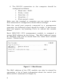
With the serial port properly connected to a management
computer, the following screen should be visible. If this screen
does not appear, try pressing Ctrl+r to refresh the console
screen.
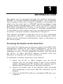
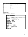
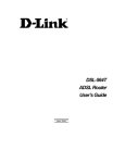
Each DES-7003 CPU management module is assigned a
unique MAC address by the factory. This MAC address cannot
be changed, and can be found from the initial boot console
screen – shown below.
Figure 1- 1. Boot Screen
The MAC address of the CPU module can also be viewed by
requesting a list of basic information about the switch (see
show switch command in Chapter 4).
2
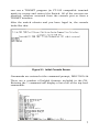
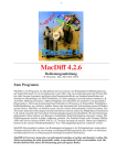
Figure 1- 2. Initial Console Screen User Name Prompt
There is no initial username or password. Just press the enter
key at the User Name prompt and again at the Passwrod
prompt to display the CLI input cursor − DES7000:4@# (or
DES7100:4@# for the DES-7100). This is the command line
where all commands are input.
3
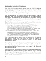
Setting the Switch’s IP Address
The DES-7000 series switch must have a TCP/IP address
assigned to it so that a network management system (Webbased, TELNET, etc.) can find it on the network. You can use
the console manager to access the system’s management
software to view or change it’s IP settings.
The IP address for the switch must be set before it can be
managed with the web-based manager or TELNET session.
The switch IP address can be automatically set using BOOTP
or DHCP protocols, in which case the actual address assigned
to the switch must be known.
The IP address may be set using the Command Line Interface
(CLI) over the console serial port as follows:
1. Starting at the command line prompt DES7000:4@# −
enter the commands config ip ipaddress
xxx.xxx.xxx.xxx/yyy.yyy.yyy.yyy. Where the x’s
represent the IP address to be assigned to the switch and
the y’s represent the corresponding subnet mask.
2. Alternaltively, you can enter DES7000:4@# − enter the
commands config ip ipaddress xxx.xxx.xxx.xxx/z.
Where the x’s represent the IP address to be assigned to
the IP interface and the z represents the corresponding
number of subnets in CIDR notation.
The IP interface on the switch can be assigned an IP address
and subnet mask and can then be used to connect a
management station to the switch’s TELNET or web-based
management agent.
It may be necessary to designate a default gateway to allow
packets to be sent outside the switch’s subnet. You can do this
manually by typing the command config ip gateway
xxx.xxx.xxx.xxx/yyy.yyy.yyy.yyy or config ip gateway
xxx.xxx.xxx.xxx/z.
The may also be configured to obtain IP settings automatically
from a BOOTP or DHCP server. In this case the switch gets its
IP settings including gateway IP from a server. Please read
Chapter 5, Switch IP Configuration for a complete description
of the config ip command set.
4
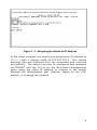
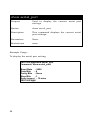
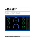
Figure 1- 3. Assigning the Switch an IP Address
In the above example, the switch was assigned an IP address of
10.1.1.1 with a subnet mask of 255.255.255.0. The system
message Success indicates that the command was executed
successfully. The switch can now be configured and managed
via TELNET and the CLI or via the Web-based management
agent using the above IP address to connect to the switch
through the Management port (labeled: Mgmt) on the CPU
module, or through the network.
5
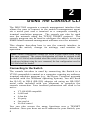
2
U SING
THE
C ONSOLE CLI
The DES-7000 supports a console management interface that
allows the user to connect to the switch’s management agent
via a serial port and a terminal or a computer running a
terminal emulation program. The console can also be used
over the network using the TCP/IP TELNET protocol. The
console program can be used to configure the switch to use an
SNMP-based network management software over the network.
This chapter describes how to use the console interface to
access the switch, change its settings, and monitor its
operation.
Note: Switch configuration settings are saved to non-volatile RAM using
the save command. The current configuration will then be retained in the
switch’s NV-RAM, and reloaded when the switch is rebooted. If the switch
is rebooted without using the save command, the last configuration saved to
NV-RAM will be loaded.
Connecting to the Switch
The console interface is used by connecting the Switch to a
VT100-compatible terminal or a computer running an ordinary
terminal emulator program (e.g., the Hyper Terminal program
included with the Windows operating system). You will need
the RJ-45 to DB-9 (RS-232) adapter nd using an RS-232C
serial cable included with you shipment to complete the
console connection. Your terminal parameters will need to be
set to:
•
•
•
•
•
•
VT-100/ANSI compatible
9,600 baud
8 data bits
No parity
One stop bit
No flow control
You can also access the same functions over a TELNET
interface. Once you have set an IP address for your Switch, you
6
can use a TELNET program (in VT-100 compatible terminal
mode) to access and control the Switch. All of the screens are
identical, whether accessed from the console port or from a
TELNET interface.
After the switch reboots and you have loged in, the console
looks like this:
Figure 2-1. Initial Console Screen
Commands are entered at the command prompt, DES-7000:4#.
There are a number of helpful features included in the CLI.
Entering the ? command will display a list of all of the top-level
commands.
7
Figure 2-2. The ? Command
The dir command has the same function as the ? command.
When you enter a command without its required parameters,
the CLI will prompt you with a Next possible completions:
message.
Figure 2-4. Example Command Parameter Help
In this case, the command config account was entered
without the parameter <username>. The CLI will then prompt
you to enter the <username> with the message, Next possible
completions:. Every command in the CLI has this feature, and
complex commands have several layers of parameter
prompting.
All commands in the CLI function in this way. In addition, the
syntax of the help prompts are the same as presented in this
manual − angle brackets < > indicate a numerical value or
character string, braces { } indicate optional parameters or a
choice of parameters, and brackets [ ] indicate required
parameters.
If a command is entered that is unrecognized by the CLI, the
top-level commands will be displayed under the Available
commands: prompt.
8
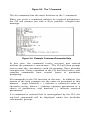
Figure 2-6. The Available Commands Prompt
The top-level commands consist of commands like show or
config.
Most of these commands require one or more
parameters to narrow the top-level command.
This is
equivalent to show what? or config what? Where the what? is
the next parameter.
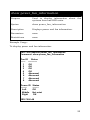
For example, if you enter the show command with no
additional parameters, the CLI will then display all of the
possible next parameters.
9
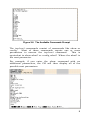
Figure 2-6. Next possible completions: Show Command
In the above example, all of the possible next parameters for
the show command are displayed. At the next command
prompt, the up arrow was used to re-enter the show command,
followed by the account parameter. The CLI then displays the
user accounts configured on the switch.
10
3
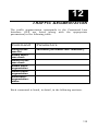
C OMMAND S YNTAX
The following symbols are used in this manual to describe how
command entries are made and values and arguments are
specified in this manual. The on-line help contained in the CLI
and available through the console interface, uses the same
syntax.
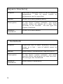
<angle brackets>
Purpose
Encloses a variable or value which must be
specified.
Syntax
config account <username>
Description
In the above syntax example, you must
supply a previously created username in
the <username> space. Do not type the
angle brackets.
Example
Command
config account Irvine999
11
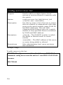
[square brackets]
Purpose
Encloses a required value or set of required
arguments.
One or more values or
arguments can be specified.
Syntax
create account [admin/user]
Description
In the above syntax example, you must
specify either an admin or a user level
account to be created. Do not type the
square brackets.
Example
Command
create account admin
/ backslash
Purpose
Seperates two or more mutually exclusive
items in a list − one of which must be
entered.
Syntax
show snmp [community/trap receiver]
Description
In the above syntax example, you must
specify either community or trap receiver.
Do not type the backslash.
Example
Command
show snmp community
12
{braces}
Purpose
Encloses an optional
optional arguments.
value
or
set
of
Syntax
config igmp [<ipif_name>/all] {version
<value>/query_interval
<sec>/max_response_time <sec>/
robustness_variable
<value>/last_member_query_interval
<vlaue>/state [enabled/disabled]}
Description
In the above syntax example, you must
choose to enter an IP interface name in the
<ipif_name> space or all, but version
<value>, query_interval <sec>,
max_response_time <sec>,
robustness_variable <value>,
last_member_query_interval <value>, and
state [enabled/disabled] are all optional
arguments. You can specify any or all of
the arguments contained by braces. Do not
type the braces.
Example
command
config igmp all version 2
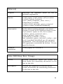
Line Editing Key Usage
Delete
Deletes characeter under the cursor and
then shifts the remaining characters in the
line to the left.
Backspace
Deletes the character to the left of the
cursor and shifts the remaining characters
in the line to the left.
13
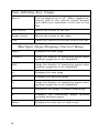
Line Editing Key Usage
Insert
Can be toggled on or off. When toggled on,
inserts text at the current cursor positon
and shifts the remainder of the line to the
left.
Left Arrow
Moves the cursor to the left.
Right Arrow
Moves the cursor to the right.
Tab
Shifts the cursor to the next field to the left.
Multiple Page Display Contr ol Keys
Space
Displays the next page.
CTRL+c
Stops the display of remaining pages when
multiple pages are to be displayed.
ESC
Stops the display of remaining pages when
multiple pages are to be displayed.
n
Displays the next page.
p
Displays the previous page.
q
Stops the display of remaining pages when
multiple pages are to be displayed.
r
Refreshes the pages currently displaying.
a
Displays the remaining
pausing between pages.
Enter
Displays the next line or table entry.
14
pages
without
4
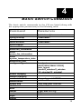
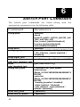
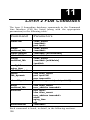
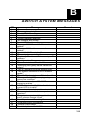
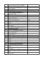
B ASIC S WITCH C OMMANDS
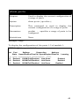
The basic switch commands in the CLI are listed (along with
the appropriate parameters) in the following table.
Command
Parameters
create account
config account
show account
delete account
show session
show switch
show unit_information
show
power_fan_information
show
system_temperature_state
show serial_port
config serial_port
[admin/user] <username>
<username>
enable clipaging
disable clipaging
enable telnet
disable telnet
enable web
disable web
save
reboot
reset
login
logout
<username>
baud_rate
[9600/19200/38400/115200]
auto_logout
[never/2_minutes/5_minutes
/10_minutes/15_minutes]
<tcp_udp_port 1-65535>
<tcp_udp_port 1-65535>
{ [all | unit <2-13>]}
{all}
15
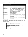
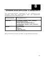
Each command is listed, in detail, in the following sections.
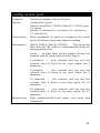
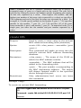
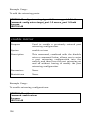
create account
Purpose
Used to create user accounts
Syntax
create account [admin/user] <username>
Description
The create account command is used to
create user accounts that consist of a
username of 1 to 15 characters and a
password of 0 to 15 characters. Up to 8
user accounts can be created.
Parameters
Admin <username>
User <username>
Restrictions
Only Administrator-level users can issue
this command.
Usernames can be between 1 and 15
characters.
Passwords can be between 0 and 15
characters.
Example Usage:
To create an administrator-level user account with the
username “dlink”.
DES7000:4@#create account admin dlink
Command: create account admin dlink
Enter a case-sensitive new password:****
Enter the new password again for confirmation:****
Success.
DES7000:4@#
16
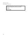
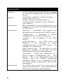
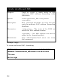
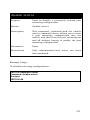
config account
Purpose
Used to configure user accounts
Syntax
config account <username>
Description
The config account command configures a
user account that has been created using
the create account command.
Parameters
<username>
Restrictions
Only Administrator-level users can issue
this command.
Usernames can be between 1 and 15
characters.
Passwords
characters.
can
be
between
0
15
Example Usage:
To configure the user password of “dlink” account:
DES7000:4@#config account dlink
Command: config account dlink
Enter a old password:****
Enter a case-sensitive new password:****
Enter the new password again for confirmation:****
Success.
DES7000:4@#
17
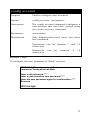
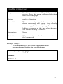
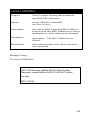
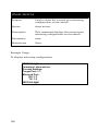
show account
Purpose
Used to display user accounts
Syntax
show account
Description
Displays all user accounts created on the
switch. Up to 8 user accounts can exist on
the switch at one time.
Parameters
None.
Restrictions
None.
Example Usage:
To display the accounts that have been created:
DES7000:4@#show account
Command: show account
Current Accounts:
Username
Access Level
-------------------------System
user
dlink
Admin
DES7000:4@#
18
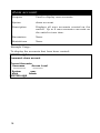
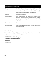
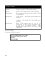
delete account
Purpose
Used to delete an existing user account
Syntax
delete account <username>
Description
The delete account command deletes a user
account that has been created using the
create account command.
Parameters
<username>
Restrictions
Only Administrator-level users can issue
this command.
Example Usage:
To delete the user account “System”:
DES7000:4@#delete account System
Command: delete account System
Success.
DES7000:4@#
19
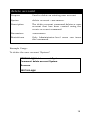
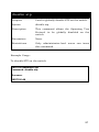
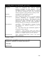
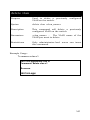
show session
Purpose
Used to display a list of currently logged-in
users.
Syntax
show session
Description
This command displays a list of all the
users that are logged-in at the time the
command is issued.
Parameters
none
Restrictions
Only Administrator-level users can issue
this command.
Example Usage:
To display the way that the users logged in:
DES7000:4@#show session
ID Live Time
--- -----------8 0:17:16.2
20
From
Level Name
------------ ----- --------Serial Port 4 Anonymous
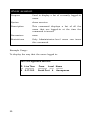
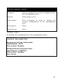
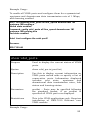
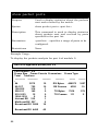
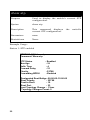
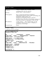
show switch
Purpose
Used to display information about the
switch.
Syntax
show switch
Description
This command displays information about
the switch.
Parameters
None.
Restrictions
None.
Example Usage:
To display the switch information:
DES7000:4@#show switch
Command: show switch
Device Type : DES7000 Fast Ethernet Switching System
Module ID
:1
MAC Address : 00-01-02-03-04-00
IP Address
: 10.90.90.90 (Manual)
VLAN Name
: default
Subnet Mask
: 255.0.0.0
Default Gateway : 0.0.0.0
System Name
:
System Location :
System Contact :
Spanning Tree
: Disabled
IGMP Snooping : Disabled
TELNET
: Enabled (TCP 23)
WEB
: Enabled (TCP 80)
RMON
: Disabled
DES7000:4@#
21
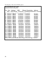
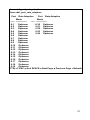
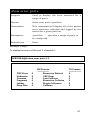
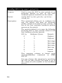
show unit_information
Purpose
Used to display information about the
individual module units.
Syntax
show unit_information
Description
Displays information about the installed
modules.
Parameters
none
Restrictions
none
Example Usage:
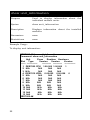
To display unit information:
DES7000:4#show unit_information
Command: show unit_information
Unit
Prom
Runtime Hardware
Slot Type
Version
Version
Version
------- ------------------------- ------------ -------------1 DES7000 CPU 1.00.000 1.00.000 1
2 N/A
N/A
N/A
N/A
3 N/A
N/A
N/A
N/A
4 DES7010 VDSL 0.00.002 0.00.008 0
5 N/A
N/A
N/A
N/A
6 N/A
N/A
N/A
N/A
7 N/A
N/A
N/A
N/A
8 N/A
N/A
N/A
N/A
9 N/A
N/A
N/A
N/A
10 N/A
N/A
N/A
N/A
11 N/A
N/A
N/A
N/A
12 N/A
N/A
N/A
N/A
13 N/A
N/A
N/A
N/A
DES7000:4#
22
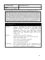
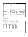
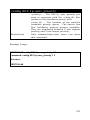
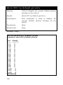
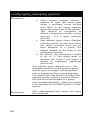
show power_fan_information
Purpose
Used to display information about the
systeem fans and RPS units.
Syntax
show power_fan_information
Description
Displays power and fan information.
Parameters
none
Restrictions
none
Example Usage:
To display power and fan information:
DES-7000:4#show power_fan_information
Command: show power_fan_information
Fan ID Status
------ -----------1
OK
2
OK
3
OK
4
OK
5
Abnormal
6
Abnormal
7
Abnormal
8
Abnormal
Power ID
-------Left
Middle
Right
Status
-------OK
Not exist
OK
DES-7000:4#
23
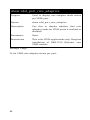
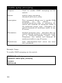
show serial_port
Purpose
Used to display the current serial port
settings.
Syntax
show serial_port
Description
This command displays the current serial
port settings.
Parameters
None.
Restrictions
none
Example Usage:
To display the serial port setting:
DES7000:4@#show serial_port
Command: show serial_port
Baud Rate : 9600
Data Bits
:8
Parity Bits : None
Stop Bits
:1
Auto-Logout : 10 mins
DES7000:4@#
24
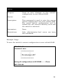
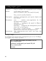
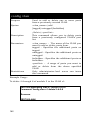
config serial_port
Purpose
Used to configure the serial port.
Syntax
config serial_port
{baud_rate[9600/19200/38400/115200]/aut
o_logout
[never/2_minutes/5_minutes/10_minutes/
15_minutes]}
Description
This command is used to configure the serial
port’s baud rate and auto logout settings.
Parameters
[9600/19200/38400/115200] − The serial bit
rate that will be used to communicate with the
management host.
never − no time limit on the length of time the
console can be open with no user input.
2_minutes − the console will log out the
current user if there is no user input for 2
minutes.
5_minutes − the console will log out the
current user if there is no user input for 5
minutes.
10_minutes − the console will log out the
current user if there is no user input for 10
minutes.
15_minutes − the console will log out the
current user if there is no user input for 15
minutes.
Restrictions
Only administrator-level users can issue this
command.
25
Example Usage:
To configure baud rate:
DES7000:4@#config serial_port baud_rate 9600
Command: config serial_port baud_rate 9600
Success.
DES7000:4@#
26
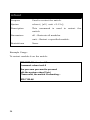
enable clipaging
Purpose
Used to pause the scrolling of the console
screen when the show command displays
more than one page.
Syntax
enable clipaging
Description
This command is used when issuing the
show command will cause the console
screen to rapidly scroll through several
pages.
This command will cause the
console to pause at the end of each page.
The default setting is enabled.
Parameters
None.
Restrictions
Only administrator-level users can issue
this command.
Example Usage:
To enable pausing of the screen display when show
command output reaches the end of the page:
DES7100:4#enable clipaging
Command: enable clipaging
Success.
DES7100:4#
27
disable clipaging
Purpose
Used to disable the pausing of the console
screen scrolling at the end of each page
when the show command would display
more than one screen of information.
Syntax
disable clipaging
Description
This command is used to disable the
pausing of the console screen at the end of
each page when the show command would
display
more
than
one
screen
of
information.
Parameters
None.
Restrictions
Only administrator-level users can issue
this command.
Example Usage:
To disable pausing of the screen display when show command
output reaches the end of the page:
DES7000:4#disable clipaging
Command: disable clipaging
Success.
DES7000:4#
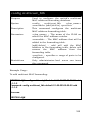
28
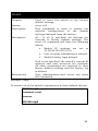
enable telnet
Purpose
Used to enable communication with and
management of the switch using the
TELNET protocol.
Syntax
enable telnet <tcp_port_number>
Description
This command is
TELNET protocol on
can specify the TCP
the switch will use
requests.
Parameters
<tcp_port_number>
−
the TCP port
number. TCP ports are numbered between
1 and 65535. The “well-known” TCP port
for the TELNET protocol is 23.
Restrictions
Only administrator-level users can issue
this command.
used to enable the
the switch. The user
or UDP port number
to listen for TELNET
Example Usage:
To enable TELNET and configure port number:
DES7100:4#enable telnet 23
Command: enable telnet 23
Success.
DES7100:4#
29
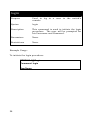
disable telnet
Purpose
Used to disable the TELNET protocol on the
switch.
Syntax
disable telnet
Description
This command is used to disable the
TELNET protocol on the switch.
Parameters
None.
Restrictions
Only administrator-level users can issue
this command.
Example Usage:
To disable the TELNET protocol on the switch:
DES7100:4#disable telnet
Command: disable telnet
Success.
DES7100:4#
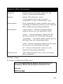
30
enable web
Purpose
Used
to
enable
the
HTTP-based
management software on the switch.
Syntax
enable web <tcp_port_number>
Description
This command is used to enable the Webbased management software on the switch.
The user can specify the TCP port number
the switch will use to listen for TELNET
requests.
Parameters
<tcp_port_number>
−
the TCP port
number. TCP ports are numbered between
1 and 65535. The “well-known” port for the
Web-based management software is 80.
Restrictions
Only administrator-level users can issue
this command.
Example Usage:
To enable HTTP and configure port number:
DES7100:4#enable web 80
Command: enable web 80
Success.
DES7100:4#
31
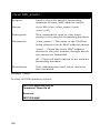
disable web
Purpose
Used
to
disable
the
HTTP-based
management software on the switch.
Syntax
disable web
Description
This command disables the Web-based
management software on the switch.
Parameters
None.
Restrictions
Only administrator-level users can issue
this command.
Example Usage:
To disable HTTP:
DES7100:4#disable web
Command: disable web
Success.
DES7100:4#
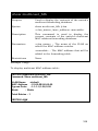
32
save
Purpose
Used to save changes in the switch’s
configuration to non-volitale RAM.
Syntax
save
Description
This command is used to enter the current
switch configuration into non-volitale RAM.
The saved swtich configuration will be
loaded into the switch’s memory each time
the switch is restarted.
Parameters
None.
Restrictions
Only administrator-level users can issue
this command.
Example Usage:
To save the switch’s current configuration to non-volitale RAM:
DES-7000:4#save
Command: save
*********************
*
*
* Do not power off! *
*
*
*********************
Saving all configurations to NV-RAM.......... Done.
DES-7000:4#
33
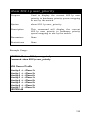
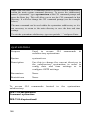
reboot
Purpose
Used to restart the switch.
Syntax
reboot { [all | unit <2-13>]}
Description
This command is used to restart the
switch.
Parameters
all – Restarts all modules.
unit – Restart a specified module.
Restrictions
None.
Example Usage:
To restart module 6 on the switch:
DES-7100:4#reboot unit 6
Command: reboot unit 6
Are you sure you want to proceed
with the system reboot?(y/n)
Please wait, the switch is rebooting...
DES-7100:4#
34
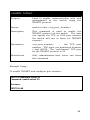
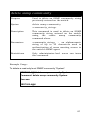
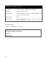
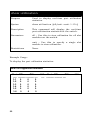
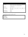
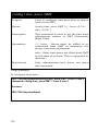
reset
Purpose
Used to reset the switch to the factory
default settings.
Syntax
reset {all}
Description
This command is used to restore the
switch’s configuration to the default
settings assinged from the factory.
Parameters
all – If all is specified, all settings are
restored to factory default settings. The
reset all command will have the following
effects:
•
Switch IP settings are
10.90.90.90/255.0.0.0
•
User account information is deleted.
•
Switch history logis deleted.
set
to
If all is not specified, the switch’s current IP
address and user accounts are retained.
All other parameters are restored to their
factory default settings and the history log
is deleted
Restrictions
Only administrator-level users can issue
this command.
Example Usage:
To restore all of the switch’s parameters to their default values:
DES7000:4@#reset
Command: reset
Success.
DES7000:4@#
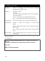
35
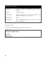
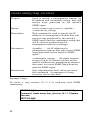
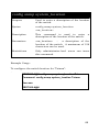
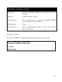
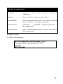
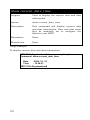
login
Purpose
Used to log in a user to the switch’s
console.
Syntax
login
Description
This command is used to initiate the login
procedure. The user will be prompted for
his Username and Password.
Parameters
None.
Restrictions
None.
Example Usage:
To initiate the login procedure:
DES7000:4@#login
Command: login
UserName:
36
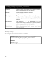
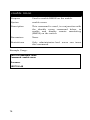
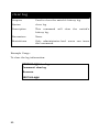
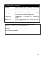
logout
Purpose
Used to log out a user from the swtich’s
console.
Syntax
logout
Description
This command terminates the current
user’s session on the switch’s console.
Parameters
None.
Restrictions
None.
Example Usage:
To terminate the current user’s console session:
DES7000:4@#logout
37
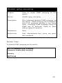
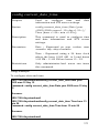
5
S WITCH IP C ONFIGURATION
Switch IP settings and management VLAN designation are
listed below along with the required parameters.
Command Parameters
config ip
ipaddress [<IP address/subnet mask>/gateway
<IP address>]
vlan <vlan_name>
bootp/dhcp
Config IP commands are are described, in detail, in the
following sections.
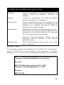
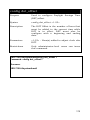
38
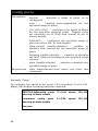
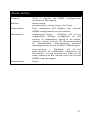
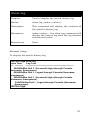
config ip [ipaddress/gateway]
Purpose
Used to manually set switch IP address and
subnet mask or Default Gateway IP
address.
Syntax
config ip [ipaddress <IP address/subnet
mask>/gateway <IP address>]
Description
Used to manually assign IP settings to the
switch and if necessary to designate an IP
address as a default gateway to different
networks or subnet groups.
Parameters
ipaddress<xxx.xxx.xxx.xxx/yyy.yyy.yyy.yyy>
Where the x’s represent the IP address to be
assigned to the switch and the y’s represent
the corresponding subnet mask.
gateway <xxx.xxx.xxx.xxx> Where the x’s
represent the IP address of the default
gateway device.
Restrictions
Only Administrator-level users can issue
this command.
Example Usage:
To manually assign an IP address of 10.41.44.101 and subnet
mask of 255.0.0.0 to the switch, and designate a default
gateway of 10.1.1.254 use the following sequence of commands:
DES-7100:4#config ip ipaddress 10.41.44.101/255.0.0.0
Command: config ip ipaddress 10.41.44.101/8
Success.
DES-7100:4#config ip gateway 10.1.1.254
Command: config ip gateway 10.1.1.254
Success.
DES-7100:4#
39
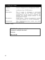
config ip vlan
Purpose
Used to designate the management VLAN.
Syntax
config ip vlan <VLAN name>
Description
This is used to designate a previously
created VLAN as the VLAN from which
management of the switch is allowed. By
default, the VLAN named default is the
management VLAN.
Parameters
VLAN name – Name of previously created
VLAN (see Chapter 14, VLAN Commands).
Restrictions
Only Administrator-level users can issue
this command.
Example Usage:
DES-7100:4#config ip vlan vlan1
Command: config ip vlan vlan1
Success.
DES-7100:4#
40
config ip [bootp/dhcp]
Purpose
Use this to configure the swich to obtain IP
settings, including IP address, subnet mask
and gateway IP address fom a BOOTP or
DHCP server.
Syntax
config ip [bootp/dhcp]
Description
Used to configure the switch to be a client
for a BOOTP or DHCP server.
Parameters*
bootp – Configures the switch to obtain IP
settings from a BOOTP server.
dhcp – Configure the switch to obtain IP
settings from a DHCP server.
Restrictions
Only Administrator-level users can issue
this command.
Example Usage:
To configure the switch to be a DHCP client:
DES-7100:4#config ip dhcp
Command: config ip dhcp
Success.
DES-7100:4#
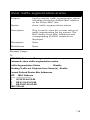
* Important Note: The GBIC uplink ports on the DES-7003 CPU module
are currently not compatible with BOOOTP and DHCP client modes. The
Switch can receive BOOTP or DHCP settings instructions through the
Management Port on the Primary Master CPU module. However, since this
port is not intended for routine network traffic and should not be used to
uplink the Switch to the network, it should be connected directly to a nonnetworked DHCP or BOOTP server with the function limited to providing
service only to the Switch.
41
6
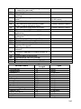
S WITCH P ORT C OMMANDS
The switch port commands are listed (along
appropriate parameters) in the following table.
with
the
Command
Parameters
config ports
<portlist>
speed
[auto/10_half/10_full/100_half/100_full/
1000_half/1000_full]
flow_control [enabled/disabled]
learning [enabled/disabled]
state [enabled/disabled]
<portlist>
{speed [auto| 10_half| 10_full| 100_half
| 100_full] flow_control [enabled |
disabled]}
show ports
config mgmt_port
show mgmt_port
config
vdsl_port_loopback_test
show
vdsl_loopback_test
config vdsl_ports
show vdsl_ports
show vdsl_tx_power
42
<portlist> type [local/line] count <1-10>
{[all | unit <int 2-13>]}
[ <portlist>/ all ] {line_speed
downstream
[Mode_0/512K/1M/2M/3M/4M/5M/8M/10
M/15M]
upstream
[Mode_0/512K/1M/2M/3M/4M/5M/8M/10
M/15M]
/learning [enabled / disabled]
/state [enabled / disabled]
/rate_adaptive_mode [disabled /
default / optimum]}
{<portlist>}
{<portlist>}
Command
Parameters
Show
vdsl_port_rate_adaptive
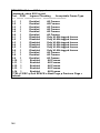
Each command is listed, in detail, in the following sections.
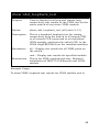
Note: Commands that use a <portlist> parameter allow you to specify a sequential
range of ports or a single port on the switch. The port list is specified by listing the
lowest slot number and the beginning port number on t hat slot, separated by a
colon. Then highest slot number, and the highest port number of the range (also
separeted by a colon) are specified. The beginning and end of the port list range
are seperated by a dash. For example, 6:1 would specify module in slot number 6,
port 1. 7:24 specifies module in slot number 7, port 24. 6:1 -7:24 specifies all of
the ports between module 6, port 1 and module 7, port 24 − in numerical order. For
a single port, just enter the slot number and port number separated by a colon.
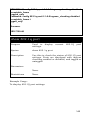
config ports
Purpose
Used to configure the switch’s Ethernet port
settings. For VDSL ports on the DES-7010
switch module, use the config_vdsl_ports
command. Ports on the DES-7006 switch
module have a fixed speed and duplex (100
Mbps Full) and therefore these can not be
configured.
Syntax
config ports [<portlist>] {speed
[auto/10_half/10_full/100_half/100_half/
1000_half/1000_full]
flow_control [enabled/disabled]
learning [enabled/disabled]
state [enabled/disabled]}
Description
This command allows for the configuration of
the switch’s Ethernet ports. Only the ports
listed in the <portlist> will be affected.
43
config ports
Parameters
portlist −
configured.
specifies a range of ports to be
auto
−
enables auto-negotiation for the
specified range of ports.
[10/100/1000] − configures the speed in Mbps
for the specified range of ports. Gigabit ports
are statically set to 1000 and cannot be set to
slower speeds.
[half/full] − configures the specified range of
ports as either full- or half-duplex.
Flow_control [enable/disable] − enables or
disables flow control for the specified range of
ports.
learning [enable/disable] − enables or disables
the MAC address learning on the specified range
of ports.
state [enable/disable] − enables or disables the
specified range of ports.
Restrictions
Only administrator-level users can issue this
command.
Example Usage:
To configure the speed of the ports 1-24 of module 3 to be 100
Mbps, full-duplex, learning and state enabled:
DES7000:4@#config ports 3:1-3:24 speed 100_full
learning on state enable
Command: config ports
learning on state enable
Success.
44
3:1-3:24
speed
100_full
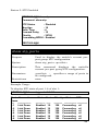
show ports
Purpose
Used to display the current configuration of
a range of ports.
Syntax
show ports {<portlist>}
Description
This command is used to display the
current configuration of a range of ports.
Parameters
portlist − specifies a range of ports to be
configured.
Restrictions
None.
Example Usage:
To display the configuration of the ports 1-3 of module 1:
DES7000:4@#show ports 1:1-1:3
Port
----1:1
1:2
1:3
Port
Settings
Connection
Address
State Speed/Duplex/FlowCtrl Speed/Duplex/FlowCtrl Learning
-------- --------------------- --------------------- -------Enabled 1000M/Full/Disabled Link Down
Enabled
Enabled 1000M/Full/Disabled Link Down
Enabled
Enabled 1000M/Full/Disabled Link Down
Enabled
45
config mgmt_port
Purpose
Used to configure the management port settings.
Syntax
config mgmt_port speed
[auto/10_half/10_full/100_half/100_half]
flow_control [enable/disable]
Description
Configure management port speed, duplex and
flow control.
Parameters
auto
−
enables auto-negotiation for the
specified range of ports.
[10/100] − configures the speed in Mbps of
management port.
[half/full] − configures the management port as
either full- or half-duplex.
flow_control [enable/disable]
−
enables or
disables flow control for management port
Restrictions
Only administrator-level users can issue this
command.
Example Usage:
To configure the speed of the management port to be 100 Mbps,
full-duplex, flow control enabled:
DES7000:4@#config mgmt_port speed 100_full
flow_control enable
Command: config mgmt_port speed 100_full
flow_control enable
Success.
46
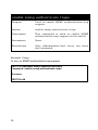
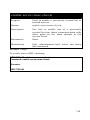
show mgmt_port
Purpose
Used to display the current configuration of
the management port.
Syntax
show mgmt_port
Description
This command is used to display the
current configuration of the management
port.
Parameters
None.
Restrictions
None.
Example Usage:
To display the configuration of the management port:
DES-7100:4#show mgmt_port
Command: show mgmt_port
Management port user setting state :
Speed/duplex : AUTO
Flow control : Enabled
Management port connection state :
Speed/duplex : 100M/FULL
Flow control : Enabled
DES-7100:4#
47
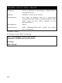
config vdsl_port_loopback_test
Purpose
Used to test local loop and remote loop
connectivity of the VDSL line.
Syntax
config vdsl_port_loopback_test <portlist>
type [local/line] count <1-10>
Description
This is a standard loopback test for testing
connectivity from the switch to remote CPE and
from the switch CPU to the VDSL chip
(PEF22824) on the installed modules.
Parameters
portlist − Specifies a range of ports to be
configured.
local - Specifies type of test as local loopback
test, that is, the internal packet path of the
switch.
line - Specifies type of test as line loopback test,
that is, the packet path from the switch to the
CPE.
count – Specifies number of packets sent for the
test.
Restrictions
This is for VDSL applications only. Requires
installation of DES-7010 Ethernet over VDSL
module.
Example Usage:
To configure a single port (slot 6, port 5) VDSL line loopback
test for connectivity.
DES-7100:4#config vdsl_port_loopback_test 6:5-6:5 type line count 5
Command: config vdsl_port_loopback_test 6:5 type line count 5
Success.
DES-7100:4#
48
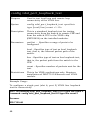
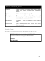
show vdsl_loopback_test
Purpose
Used to display local loop and remote loop
connectivity test results of the VDSL line for the
entire switch of any entire VDSL module.
Syntax
show vdsl_loopback_test [all/unit<2-13]
Description
This is a standard loopback test for testing
connectivity from the switch to all remote CPE
or all remote CPE connected to an individual
VDSL module; and from the switch CPU to the
VDSL chip(PEF22S24) on the installed modules.
Parameters
all – Display test results for all VDSL ports on
the switch.
unit – Display test results for specified module.
Restrictions
This is for VDSL applications only. Requires
installation of DES-7010 Ethernet over VDSL
module.
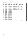
Example Usage:
To show VDSL loopback test results for VDSL module unit 6:
49
DES-7100:4#show vdsl_loopback_test unit 6
Command: show vdsl_loopback_test unit 6
Port State Count Type
Port State
Count Type
Fail/Total
Fail/Total
----- -------- ---------- ------ ----- -------- ---------- -----6:1 Finish 0 / 10 Line
6:20 Finish 0 / 10 Line
6:2 Finish 0 / 10 Line
6:21 Finish 0 / 10 Line
6:3 Finish 0 / 10 Line
6:22 Finish 0 / 10 Line
6:4 Finish 0 / 10 Line
6:23 Finish 0 / 10 Line
6:5 Finish 0 / 10 Line
6:24 Finish 0 / 10 Line
6:6 Finish 0 / 10 Line
6:7 Finish 0 / 10 Line
6:8 Finish 0 / 10 Line
6:9 Finish 0 / 10 Line
6:10 Finish 0 / 10 Line
6:11 Finish 0 / 10 Line
6:12 Finish 0 / 10 Line
6:13 Finish 0 / 10 Line
6:14 Finish 0 / 10 Line
6:15 Finish 0 / 10 Line
6:16 Finish 0 / 10 Line
6:17 Finish 0 / 10 Line
6:18 Finish 0 / 10 Line
6:19 Finish 0 / 10 Line
CTRL+C ESC q Quit SPACE n Next Page p Previous Page r Refresh
50
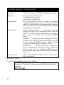
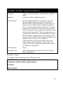
config vdsl_ports
Purpose
Used to customize upstream and downstream
data transmission rates for VDSL ports.
Syntax
config vdsl_ports [ <portlist>/ all ]
{line_speed
downstream
[Mode_0/512K/1M/2M/3M/4M/5M/8M/10M
/15M]
upstream
[Mode_0/512K/1M/2M/3M/4M/5M/8M/10M
/15M]
/ learning [enabled / disabled]
/ state [enabled / disabled]
/ rate_adaptive_mode [disabled / default /
optimum]}
Description
Use this to customize VDSL port upstream and
downstream data transmission speeds or allow
the switch to automatically adjust to the best
possible rate.
51
config vdsl_ports
Parameters
downstream – Downstream data transmission
speed speed, specify speed as Mode 0, 512 Kbps
or from 1 – 15 Mbps.
upstream – Upstream data transmission speed
speed, specify speed as Mode 0, 512 Kbps or
from 1 – 15 Mbps.
Mode 0 – This is the default setting for VDSL
ports. It specifies a downstream speed of 4Mbps
and upstream speed of 1Mbps.
rate adaptive mode – When the VDSL rate
adaptive mode is enabled, the switch
automatically senses line condition and adjusts
downstream and upstream speeds if the set rate
cannot be maintained. The default setting will
set speed to Mode 0 when a rate can no longer
be supported.
optimum – When rate adaptive mode is enabled,
this sets speed to Mode 0 but then tests the
downstream and upstream speed and raises
each incrementally to achieve the best
performance level.
state – Enable or disable the listed ports.
learning – When learning is enabled, MAC
addresses are automatically added to the
forwarding table. When disabled, any additions
to the forwarding table must be entered
manually.
Restrictions
52
This is for VDSL applications only. Requires
installation of DES-7010 Ethernet over VDSL
module.
Example Usage:
To enable all VDSL ports and configure them for a symmetrical
upstream and downstream data transmission rate of 1 Mbps,
with learning enabled
DES-7100:4#config vdsl_ports all line_speed downstream 1M
upstream 1M learning e
nabled state enabled
Command: config vdsl_ports all line_speed downstream 1M
upstream 1M learning ena
bled state enabled
Note! Just configure the exist port!!
Success.
DES-7100:4#
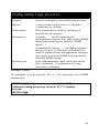
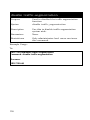
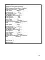
show vdsl_ports
Purpose
Used to display the current status of VDSL
ports.
Syntax
show vdsl_ports {portlist}
Description
Use this to display current information on
VDSL ports switch wide or specify a list of
consecutive ports. Information displayed
includes
port
state,
upstream
and
downstream data transmission rates, link
status and learning status.
Parameters
portlist – Ports may be specified following
the standard format, if no portlist is
specified all VDSL ports are displayed.
Restrictions
This is for VDSL applications only. Requires
installation of DES-7010 Ethernet over
VDSL module.
Example Usage:
53
To display a list of all VDSL ports:
DES-7000:4#show vdsl_ports
Command: show vdsl_ports
Port
Port Settings
VDSL
Ethernet Connection Address
State DS/US Speed Connection Speed/Duplex/FlowCtrl Learning
----- -------- ----------- ----------- --------------------- -------2:1 Enabled 4M/1M
Link Down Link Down
Enabled
2:2 Enabled 4M/1M
Link Down Link Down
Enabled
2:3 Enabled 4M/1M
Link Down Link Down
Enabled
2:4 Enabled 4M/1M
Link Down Link Down
Enabled
2:5 Enabled 4M/1M
Link Down Link Down
Enabled
2:6 Enabled 4M/1M
Link Down Link Down
Enabled
2:7 Enabled 4M/1M
Link Down Link Down
Enabled
2:8 Enabled 4M/1M
Link Down Link Down
Enabled
2:9 Enabled 4M/1M
Link Down Link Down
Enabled
2:10 Enabled 4M/1M
Link Down Link Down
Enabled
2:11 Enabled 4M/1M
Link Down Link Down
Enabled
2:12 Enabled 4M/1M
Link Down Link Down
Enabled
2:13 Enabled 4M/1M
Link Down Link Down
Enabled
2:14 Enabled 4M/1M
Link Down Link Down
Enabled
2:15 Enabled 4M/1M
Link Down Link Down
Enabled
2:16 Enabled 4M/1M
Link Down Link Down
Enabled
2:17 Enabled 4M/1M
Link Down Link Down
Enabled
2:18 Enabled 4M/1M
Link Down Link Down
Enabled
2:19 Enabled 4M/1M
Link Down Link Down
Enabled
2:20 Enabled 4M/1M
Link Down Link Down
Enabled
CTRL+C ESC q Quit SPACE n Next Page p Previous Page r Refresh
54
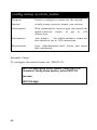
show vdsl_port_tx_power
Purpose
Used to display power settings for VDSL
ports.
Syntax
show vdsl_port_tx_power {portlist}
Description
Use this to display upstream and
downstream power settings (listed in
dBm/Hz) and signal to noise ratios (in dB)
for VDSL ports.
Parameters
portlist – Ports may be specified following
the standard format, if no portlist is
specified all VDSL ports are displayed.
Restrictions
This is for VDSL applications only. Requires
installation of DES-7010 Ethernet over
VDSL module.
Example Usage:
DES-7000:4#show vdsl_port_tx_power 2:1-2:6
Command: show vdsl_port_tx_power 2:1-2:6
Port DS Tx Power US Tx Power DS SNR
(dBm/Hz)
(dBm/Hz)
(dB)
(dB)
---- ------------- ------------- --------- ---------2:1
N/A
N/A
N/A
N/A
2:2
N/A
N/A
N/A
N/A
2:3
N/A
N/A
N/A
N/A
2:4
N/A
N/A
N/A
N/A
2:5
N/A
N/A
N/A
N/A
2:6
N/A
N/A
N/A
N/A
US SNR
CTRL+C ESC q Quit SPACE n Next Page p Previous Page r Refresh
55
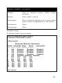
show vdsl_port_rate_adaptive
Purpose
Used to display rate adaptive mode status
per VDSL port.
Syntax
show vdsl_port_rate_adaptive
Description
Use this to display whether that rate
adaptive mode for VDSL ports is enabled or
disabled.
Parameters
None.
Restrictions
This is for VDSL applications only. Requires
installation of DES-7010 Ethernet over
VDSL module.
Example Usage:
To list VDSL rate adaptive status per port:
56
show vdsl_port_rate_adaptive
show vdsl_port_rate_adaptive
Port Rate Adaptive
Port Rate Adaptive
Mode
Mode
----- ------------------ -------------6:1
Optimum
6:20 Optimum
6:2
Optimum
6:21 Optimum
6:3
Optimum
6:22 Optimum
6:4
Optimum
6:23 Optimum
6:5
Optimum
6:24 Optimum
6:6
Optimum
6:7
Optimum
6:8
Optimum
6:9
Optimum
6:10 Optimum
6:11 Optimum
6:12 Optimum
6:13 Optimum
6:14 Optimum
6:15 Optimum
6:16 Optimum
6:17 Optimum
6:18 Optimum
6:19 Optimum
CTRL+C ESC q Quit SPACE n Next Page p Previous Page r Refresh
57
7
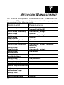
N ETWORK M ANAGEMENT
The network management commands in the Command Line
Interface (CLI) are listed (along with the appropriate
parameters) in the following table.
Command
Parameters
create snmp community
<community_string>
[readonly/readwrite]
<community_string>
<ipaddr>
<community_string>
<ipaddr>
delete snmp community
create snmp
trap_receiver
delete snmp
trap_receiver
create trusted_host
delete trusted_host
config snmp community
config snmp
trap_reciever
config snmp
system_name
config snmp
system_location
config snmp
system_contact
enable snmp traps
disable snmp traps
enable snmp authenticate
traps
disable snmp
authenticate traps
enable rmon
disable rmon
show trusted_hosts
58
<ipaddr>
<ipaddr>
<community_string> [readonly /
readwrite]
<ipaddr>
<community_string>
<sw_name>
<sw_location>
<sw_contact>
<ipaddr>
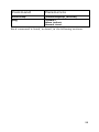
Command
Parameters
show snmp
ping
[community/trap_receiver]
<ipaddr>
times <value>
timeout <sec>
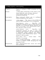
Each command is listed, in detail, in the following sections.
59
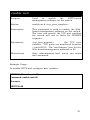
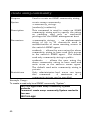
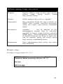
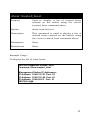
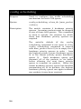
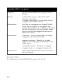
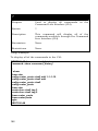
create snmp community
Purpose
Used to create an SNMP community string.
Syntax
create snmp community
<community_string>
[readonly/readwrite]
Description
This command is used to create an SNMP
community string and to specify the string
as enabling read only or read-write
privileges for the SNMP management host.
Parameters
<community_string> − an alphanumeric
string of up to 32 characters used to
authentication of users wanting access to
the switch’s SNMP agent.
readonly − allows the user using the above
community string to have read only access
to the switch’s SNMP agent. The default
read only community string is public.
readwrite − allows the user using the
above community string to have read and
write acces to the switch’s SNMP agent.
The default read write community string is
private.
Restrictions
Only administrator-level users can issue
this command.
A maximum of 4
community strings can be specified.
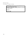
Example Usage:
To create a read-only level SNMP community “System”:
DES7000:4@#create snmp community System
readwrite
Command: create snmp community System readwrite
Success.
DES7000:4@#
60
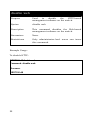
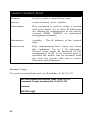
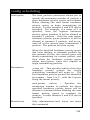
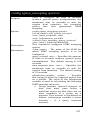
delete snmp community
Purpose
Used to delete an SNMP community string
previously entered on the switch.
Syntax
delete snmp community
<community_string>
Description
This command is used to delete an SNMP
community string entered on the switch
using
the
create
snmp
community
command above.
Parameters
<community_string> − an alphanumeric
string of up to 32 characters used to
authentication of users wanting access to
the switch’s SNMP agent.
Restrictions
Only administrator-level users can issue
this command.
Example Usage:
To delete a read-only level SNMP community “System”:
DES7000:4@#delete snmp community System
Command: delete snmp community System
Success.
DES7000:4@#
61
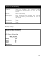
create snmp trap_receiver
Purpose
Used to specify a management station, by
IP address and community string, that will
receive traps generated by the switch’s
SNMP agent.
Syntax
create snmp trap_receiver <ipaddr>
<community_string>
Description
This command is used to specify the IP
address of a management station that will
receive traps generated by the switch’s
SNMP agent and the community string that
will be used to authenticate the
management station’s privileges.
Parameters
<ipaddr> − the IP address of a
management station that will receive SNMP
traps generated by the switch’s SNMP
agent.
<community_string> − An alpha-numeric
string of up to 32 characters that will be
used to authenticate management stations
that want to receive SNMP traps from the
swtich’s SNMP agent.
Restrictions
Only administrator-level users can issue
this command. A maximum of 4 trap
receivers can be specified.
Example Usage:
To create a trap receiver 10.1.1.1 in read-only level SNMP
community:
DES7000:4@#create snmp trap_receiver 10.1.1.1 System
Command: create snmp trap_receiver 10.1.1.1 System
Success.
DES7000:4@#
62
delete snmp trap_receiver
Purpose
Used to delete a trap receiver entry on the
switch
made
using
create
snmp
trap_reciever above.
Syntax
delete snmp trap_reciever <ipaddr>
Description
The command allows the user to delete an
SNMP trap receiver specified previously
using the create trap_receiver command
above.
Parameters
<ipaddr>
−
the IP address of the
management station that is currently
specified to receive traps from the switch’s
SNMP agent. This management station will
be deleted from the list of up to three that
can be entered using the create snmp
trap_receiver commmand above.
Restrictions
Only administrator-level users can issue
this command.
Example Usage:
To delete a trap receiver 10.1.1.1:
DES7000:4@#delete snmp trap_receiver 10.1.1.1
Command: delete snmp trap_receiver 10.1.1.1
Success.
DES7000:4@#
63
create trusted_host
Purpose
Used to create a trusted host entry.
Syntax
create trusted _host <ipaddr>
Description
This command is used to create a trusted
host entry made. Up to three IP addresses
are allowed for management of the switch
in-band SNMP, TELNET or web-based
management software.
Parameters
<ipaddr> − The IP address of the trusted
host.
Restrictions
Only administrator-level users can issue
this command. Up to 3 IP addresses.
Trusted hosts must be members of the
management VLAN. If no trusted host is
specified the switch can be accessed from
any host bay anyone who has a correct
Username and Password.
Example Usage:
To create a trusted host with an IP address 10.48.74.121:
DES7000:4@#create trusted_host 10.48.74.121
Command: create trusted_host 10.48.74.121
Success.
DES7000:4@#
64
delete trusted_host
Purpose
Used to delete a trusted host entry made
using the create trusted_host command
above.
Syntax
delete trusted _host <ipaddr>
Description
This command is used to delete a trusted
host entry made using the create
trusted_host command above.
Parameters
<ipaddr> − The IP address of the trusted
host.
Restrictions
Only administrator-level users can issue
this command.
Example Usage:
To delete a trusted host with an IP address 10.48.74.121:
DES7000:4@#delete trusted_host 10.48.74.121
Command: delete trusted_host 10.48.74.121
Success.
DES7000:4@#
65
config snmp community
Purpose
Used to create an SNMP community string.
Syntax
config snmp community
<community_string>
[readonly/readwrite]
Description
This command is used to create an SNMP
community string on the switch that will be
used to authenticate management stations
that want to access the switch using SNMP
management software.
Parameters
<community_string> − An alpha-numeric
string of up to 32 characters that will be
used to authenticate management stations
that want to access the switch’s SNMP
agent.
readonly − allows the user using the above
community string to have read only access
to the switch’s SNMP agent. The default
read only community string is public.
readwrite − allows the user using the
above community string to have read and
write acces to the switch’s SNMP agent.
The default read write community string is
private.
Restrictions
Only administrator-level users can issue
this command.
Example Usage:
To configure a SNMP community “System”:
DES7000:4@#config snmp community System readwrite
Command: config snmp community System readwrite
Success.
DES7000:4@#
66
config snmp trap_receiver
Purpose
Used to configure a specified trap receiver.
Syntax
config snmp trap_receiver <ipaddr>
<community_string>
Description
This command is used to configure a
specified trap receiver.
Parameters
<ipaddr> − the IP address of a
management station that will receive SNMP
traps generated by the switch’s SNMP
agent.
<community_string> − An alpha-numeric
string of up to 32 characters that will be
used to authenticate management stations
that want to receive SNMP traps from the
swtich’s SNMP agent.
Restrictions
Only administrator-level users can issue
this command. A maximum of 3 trap
receivers is allowed.
Example Usage:
To configure a trap receiver 10.1.1.1 in read-only level SNMP
community:
DES7000:4@#config snmp trap_receiver 10.1.1.1 System
Command: config snmp trap_receiver 10.1.1.1 System
Success.
DES7000:4@#
67
config snmp system_name
Purpose
Used to configure a name for the switch.
Syntax
config snmp system_name <sw_name>
Description
This command is used to give the switch an
alpha-numeric name of up to 128
characters.
Parameters
<sw_name> − an alpha-numeric name for
the switch of up to 128 characters.
Restrictions
Only administrator-level users can issue
this command.
Example Usage:
To configure the switch name for “DES7100”:
.
DES7000:4@#config snmp system_name DES7100
Command: config snmp system_name DES7100
Success.
DES7000:4@#
68
config snmp system_location
Purpose
Used to enter a description of the location
of the switch.
Syntax
config snmp system_location
<sw_location>
Description
This command is used to enter
description of the location of the switch.
Parameters
<sw_location>
−
a description of the
location of the switch. A maximum of 128
characters can be used.
Restrictions
Only administrator-level users can issue
this command.
a
Example Usage:
To configure the switch location for “Taiwan”:
.
DES7000:4@#config snmp system_location Taiwan
Command: config snmp system_location Taiwan
Success.
DES7000:4@#
69
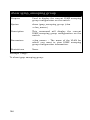
config snmp system_contact
Purpose
Used to enter the name of a contact person
who is responsible for the switch.
Syntax
config snmp system_contact
<sw_contact>
Description
This command is used to enter the name
and/or other information to identify a
contact person who is responsible for the
switch.
Parameters
<sw_contact>
−
a maximum of 128
characters used to identify a contact person
who is responsible for the switch.
Restrictions
Only administrator-level users can issue
this command.
Example Usage:
To configure the switch contact to “dlink”:
.
DES7000:4@#config snmp system_contact dlink
Command: config snmp system_contact dlink
Success.
DES7000:4@#
70
show snmp
Purpose
Used to display the SNMP configuration
entered on the switch.
Syntax
show snmp
[community_string/trap_receiver]
Description
This command will display the current
SNMP configuration on the switch.
Parameters
community_string − Displays all of the
community strings configured on the
switch. A community string is an alphanumeric string of up to 32 characters used
to authenticate management stations
wanting access to the switch’s SNMP agent.
trap_receiver − Displays all of the
trap_receiver IP addresses configured on
the switch. A trap receiver is a host on the
same subnet as the switch that can receive
SNMP trap messages.
Restrictions
None.
71
Example Usage:
To display snmp configurations:
DES7000:4@#show snmp
Command: show snmp
System Name
: DES7100
System Location : Taiwan
System Contact : dlink
SNMP Trap
: Enabled
Authenticate Traps : Enabled
Community String
Rights
---------------------------------------------------------System
Read/Write
public
Read-Only
Develop
Read-Only
private
Read/Write
Total Entries: 4
Trap Receiver:
IP Address
Community String
--------------- ---------------------------------------- -------------------10.1.1.1
Develop
Total Entries: 1
DES7000:4@#
72
show trusted_host
Purpose
Used to display a list of trusted hosts
entered on the switch using the create
trusted_host command above.
Syntax
show trusted_host
Description
This command is used to display a list of
trusted hosts entered on the switch using
the create trusted_host command above.
Parameters
None.
Restrictions
None.
Example Usage:
To display the list of trust hosts:
DES7000:4@#show trusted_host
Command: show trusted_host
Management Station IP Addresses:
IP Address: 10.48.74.121 Port: 23
IP Address: 10.48.75.100 Port: 23
IP Address: 10.48.69.23 Port: 21
DES7000:4@#
73
enable snmp traps
Purpose
Used to enable SNMP trap support.
Syntax
enable snmp traps
Description
This command is used to enable SNMP trap
support on the switch.
Parameters
None.
Restrictions
Only administrator-level users can issue
this command.
Example Usage:
To turn on SNMP trap support:
DES7100:4#enable snmp traps
Command: enable snmp traps
Success.
DES7100:4#
74
disable snmp traps
Purpose
Used to disable SNMP trap support on the
switch.
Syntax
enable snmp traps
Description
This command is used to disable SNMP
trap support on the switch.
Parameters
None.
Restrictions
Only administrator-level users can issue
this command.
Example Usage:
To prevent SNMP traps from being sent from the switch:
DES7100:4#disable snmp traps
Command: disable snmp traps
Success.
DES7100:4#
75
enable snmp authenticate traps
Purpose
Used to enable SNMP authentication trap
support.
Syntax
enable snmp authenticate traps
Description
This command is used to enable SNMP
authentication trap support on the switch.
Parameters
None.
Restrictions
Only administrator-level users can issue
this command.
Example Usage:
To turn on SNMP authentication trap support:
DES7100:4#enable snmp authenticate traps
Command: enable snmp authenticate traps
Success.
DES7100:4#
76
disable snmp authenticate traps
Purpose
Used to disable SNMP authentication trap
support.
Syntax
disable snmp authenticate traps
Description
This command is used to disable SNMP
authentication support on the switch.
Parameters
None.
Restrictions
Only administrator-level users can issue
this command.
Example Usage:
To turn off SNMP authentication trap support:
DES7100:4#disable snmp authenticate traps
Command: disable snmp authenticate traps
Success.
DES7100:4#
77
enable rmon
Purpose
Used to enable RMON on the switch.
Syntax
enable rmon
Description
This command is used, in conjunction with
the disable rmon command below, to
enable and disable remote monitoring
(RMON) on the switch.
Parameters
None.
Restrictions
Only administrator-level users can issue
this command.
Example Usage:
DES7100:4#enable rmon
Command: enable rmon
Success.
DES7100:4#
78
disable rmon
Purpose
Used to disable RMON on the switch.
Syntax
disable rmon
Description
This command is used, in conjunction with
the enable rmon command above, to
enable and disable remote monitoring
(RMON) on the switch.
Parameters
None.
Restrictions
Only administrator-level users can issue
this command.
Example Usage
DES7100:4#disable rmon
Command: disable rmon
Success.
DES7100:4#
79
ping
Description
Used to test the connectivity between
network devices.
ping <ipaddr> {times <value>} {timeout
<sec>}
This command sends Internet Control
Message Protocol (ICMP) echo messages to
a remote IP address. The remote IP address
will then “echo” or return the message.
This is used to confirm connectivity
between the switch and the remote device.
Parameters
<ipaddr> − the IP address of the remote
device.
Purpose
Syntax
times <value> − the number of individual
ICMP echo messages to be sent. A value of
0 will send an infinite ICMP echo messages.
The maximum value is 255. The default is
0
Restrictions
timeout <sec> − defines the time-out period
while waiting for a response from the
remote device. A value of 1 to 99 seconds
can be specified. The default is 1 second.
Only administrator-level users can issue
this command.
Example Usage:
To send ICMP echo message to “10.48.74.121” for 4 times:
DES7000:4@#ping 10.48.74.121 times 4
Command: ping 10.48.74.121
Reply from 10.48.74.121, time<10ms
Reply from 10.48.74.121, time<10ms
Reply from 10.48.74.121, time<10ms
Reply from 10.48.74.121, time<10ms
Ping Statistics for 10.48.74.121
Packets: Sent =4, Received =4, Lost =0
DES7000:4@#
80
8
D OWNLOAD /U PLOAD C OMMANDS
The download/upload commands in the Command Line
Interface (CLI) are listed (along with the appropriate
parameters) in the following table.
Command
Parameters
download
[[ firmware <ipaddr> <path_filename>
{[slave {[all|<2-13>]}/
master {[primary/backup/all]} ] }/
configuration <ipaddr> <path_filename>
{increment}]
configuration
log
<ipaddr>
<path_filename>
upload
Each command is listed, in detail, in the following sections.
81
download
Purpose
Syntax
Description
Parameters
Used to download and install new firmware
or a switch configuration file from a TFTP
server.
[[ firmware <ipaddr> <path_filename>
{[slave {[all/<2-13>]}/
master {[primary/backup/all]} ] }/
configuration <ipaddr> <path_filename>
{increment}]
This command is used to download a new
firmware or a switch configuration file from
a TFTP server.
firmware − download and install new
firmware on the switch from a TFTP server.
configuration
−
download
a
switch
configuration file from a TFTP server.
<ipaddr> − the IP address of the TFTP
server.
<path_filename> − the DOS path and
filename of the firmware or switch
configuration file on the TFTP server. For
example, C:\3326s.had.
unit [<unitid>/all] − all specifies all units
(switches), <unitid> is the unit id of the
switch that will receive the download.
Restrictions
82
increment − allows the download of a
partial switch configuration file.
This
allows a file to be downloaded that will
change only the switch parameters
explicitly stated in the configuration file.
All other switch parameters will remain
unchanged.
The TFTP server must be on the same IP
subnet as the switch. Only administratorlevel users can issue this command.
Example Usage:
DES7000:4@#download configuration 10.48.74.121
c:\cfg\setting.txt
Command: download configuration 10.48.74.121
c:\cfg\setting.txt
Connecting to server................... Done.
Download configuration............. Done.
DES7000:4@#
83
upload
Purpose
Used to upload the current switch settings
or the switch history log to a TFTP server.
Syntax
upload [configuration/log] <ipaddr>
<path_filename>
Description
This command is used to upload either the
switch’s current settings or the switch’s
history log to a TFTP server.
Parameters
configuration − specifies that the switch’s
current settings will be uploaded to the
TFTP server.
log − specifies that the switch history log
will be uploaded to the TFTP server.
<ipaddr> − the IP address of the TFTP
server. The TFTP server must be on the
same IP subnet as the switch.
<path_filename> − specifies the location of
the switch configuration file on the TFTP
server. This file will be replaced by the
uploaded file from the switch.
Restrictions
The TFTP server must be on the same IP
subnet as the switch. Only administratorlevel users can issue this command.
Example Usage:
DES7000:4@#upload configuration 10.48.74.121
c:\cfg\log.txt
Command: upload configuration 10.48.74.121
c:\cfg\log.txt
Connecting to server................... Done.
Upload configuration...................Done.
DES7000:4@#
84
9
N ETWORK M ONITORING
C OMMANDS
The network monitoring commands in the Command Line
Interface (CLI) are listed (along with the appropriate
parameters) in the following table.
Command
Parameters
show packet ports
show error ports
show utilitzation
clear counters
clear log
show log
<portlist>
<portlist>
{[all/unit <unit 1-13>]}
ports <portlist>
index <value>
Each command is listed, in detail, in the following sections.
Note: Commands that use a <portlist> parameter allow you to specify a
sequential range of ports or a single port on the switch. The port list is
specified by listing the lowest slot number and the beginning port number
on that slot, separated by a colon. Then highest slot number, and the
highest port number of the range (also separeted by a colon) are specified.
The beginning and end of the port list range are seperated by a dash. For
example, 6:1 would specify module in slot number 6, port 1. 7:24 specifies
module in slot number 7, port 24. 6:1-7:24 specifies all of the ports
between module 6, port 1 and module 7, port 24 − in numerical order. For a
single port, just enter the slot number and port number separated by a
colon.
85
show packet ports
Purpose
Used to display statistics about the packets
sent and received by the switch.
Syntax
show packet ports <portlist>
Description
This command is used to display statistics
about packets sent and received by ports
specified in the port list.
Parameters
<portlist> − specifies a range of ports to be
configured.
Restrictions
None.
Example Usage:
To display the packets analysis for port 6 of mudule 2:
DES7000:4@#show packet port 2:6
Port number : 2:6
Frame Size Frame Counts Frames/sec Frame Type
Total Total/sec
------------ ------------------------------------ -------64
3275
10
RX Bytes
408973 1657
65-127
755
10
RX Frames
4395
19
128-255
316
1
256-511
145
0
TX Bytes
7918
178
512-1023
15
0
TX Frames 111
2
1024-1518
0
0
Unicast RX 152
1
Multicast RX 557
2
Broadcast RX 3686
16
Broadcast RX 4495
86
42
show error ports
Purpose
Used to display the error statistics for a
range of ports.
Syntax
show error ports <portlist>
Description
This command will display all of the packet
error statistics collected and logged by the
swtich for a given port list.
Parameters
<portlist> − specifies a range of ports to
be configured.
Restrictions
None.
Example Usage:
To display the errors of the port 3 of module 1:
DES7000:4@# show error ports 1:3
CRC Error
Undersize
Oversize
Fragment
Jabber
Drop Pkts
0
0
0
0
0
0
RX Frames
--------------Excessive Deferral
CRC Error
Late Collision
Excessive Collision
Single Collission
Collision
TX Frames
---------------0
0
0
0
0
0
87
show utilization
Purpose
Used to display real-time port utilization
statistics.
Syntax
show utilization {[all/unit <unit 1-13>]}
Description
This command will display the real-time
port utilitization statistics for the switch.
Parameters
all – Use this to view utilization for all slot
modules on the switch.
unit – Use this to specify a single slot
module to view utilization.
Restrictions
None.
Example Usage:
To display the port utilization statistics:
DES7000:4@#show utilization
Port TX/sec RX/sec
----- ---------- ---------- ---1:1
0
0
0
1:2
0
0
0
1:3
0
0
0
1:4
0
0
0
1:5
0
0
0
1:6
0
0
0
88
Util Port TX/sec RX/sec
---- ---------- ---------- ----
Util
clear counters
Purpose
Used to
counters.
clear
the
switch’s
statistics
Syntax
clear counters {ports <portlist>}
Description
This command will clear the counters used
by the switch to compile statistics.
Parameters
<portlist> − specifies a range of ports to
be configured.
Restrictions
Only administrator-level users can issue
this command.
Example Usage:
To clear the counters:
DES7000:4@#clear counters ports 2:7-2:9
Command: clear counters ports 2:7-2:9
Success.
DES7000:4@#
89
clear log
Purpose
Used to clear the switch’s history log.
Syntax
clear log
Description
This command
history log.
Parameters
None.
Restrictions
Only administrator-level users can issue
this command.
Example Usage:
To clear the log information:
DES7000:4@#clear log
Command: clear log
Success.
DES7000:4@#
90
will
clear
the
switch’s
show log
Purpose
Used to display the switch history log.
Syntax
show log {index <value>}
Description
This command will display the contents of
the switch’s history log.
Parameters
index <value> − the show log command will
display the history log until the log number
reaches this value.
Restrictions
None.
Example Usage:
To display the switch history log:
DES7000:4@# show log
Index Time
Log Text
----- ---------- --------------------------------------------------------------4 000d00h50m Unit 1, Successful login through Console
(Username: Anonymous)
3 000d00h50m Unit 1, Logout through Console (Username:
Anonymous)
2 000d00h49m Unit 1, Successful login through Console
(Username: Anonymous)
1
000d00h49m Unit 1, Logout through Console (Username:
Anonymous)
DES7000:4@#
91
10
S PANNING T REE C OMMANDS
The spanning tree commands in the Command Line Interface
(CLI) are listed (along with the appropriate parameters) in the
following table.
Command
Parameters
config stp
maxage <value>
hellotime <value>
forwarddelay <value>
priority <value>
fdpdu [enabled/disabled]
<portlist>
cost <value>
priority <value>
state [enabled/disabled]
config stp_ports
enable stp
disable stp
show stp
show stp_ports
<portlist>
Each command is listed, in detail, in the following sections.
Note: Commands that use a <portlist> parameter allow you to specify a
sequential range of ports or a single port on the switch. The port list is
specified by listing the lowest slot number and the beginning port number
on that slot, separated by a colon. Then highest slot number, and the
highest port number of the range (also separeted by a colon) are specified.
The beginning and end of the port list range are seperated by a dash. For
example, 6:1 would specify module in slot number 6, port 1. 7:24 specifies
module in slot number 7, port 24. 6:1-7:24 specifies all of the ports
between module 6, port 1 and module 7, port 24 − in numerical order. For a
single port, just enter the slot number and port number separated by a
colon.
92
config stp
Purpose
Used to setup STP on the switch.
Syntax
config stp {maxage <value>/hellotime
<value>/forwarddelay
<value>/priority
<value>/fbpdu [enabled/disabled]}
This command is used to setup the
Spanning Tree Protocol (STP) for the entire
switch.
maxage <value> − the maximum amount
of time (in seconds) that the switch will
wait to receive a BPDU packet before
reconfiguring STP.
The default is 20
seconds.
hellotime <value>
−
the time interval
between transmission of configuration
messages by the root device. The default is
2 seconds.
forwarddelay <value> − the maximum
amount of time (in seconds) that the root
device will wait before changing states. The
default is 15 seconds.
priority <value>
−
a numerical value
between 0 and 65535 that is used in
determining the root device, root port, and
designated port.
The device with the
highest priority becomes the root device.
The lower the numerical value, the higher
the priority. The default is 32,768.
fbpdu [enabled/disabled] − allows the
forwarding of STP BPDU packets from other
network devices when STP is disabled on
the switch. The default is enabled.
Only administrator-level users can issue
this command.
Description
Parameters
Restrictions
93
Example Usage:
To set maxage to 18 and hellotime to 4:
DES7000:4@#config stp maxage 18 hellotime 4
Command: config stp maxage 18 hellotime 4
Success.
DES7000:4@#
94
config stp_ports
Purpose
Used to setup STP on the port level.
Syntax
config stp_ports <portlist> {cost
<value>/priority <value>/state
[enabled/disabled]
This command is used to create and
configure STP for a group of ports.
cost <value> − this defines a metric that
indicates the relative cost of forwarding
packets to the specified port list.
The
default cost for a 1000 Mbps port is 4, a
100 Mbps port is 19, and for a 10 Mbps
port the default cost is 100.
priority <value>
−
a numeric value
between 0 and 31 that is used in determing
the root and designated port in an STP port
list. The default is 16, with 0 indicating the
highest priority.
<portlist> − specifies a range of ports to
be configured.
state [enabled/disabled] − allows STP to
be enabled or disabled for the ports
specified in the port list. The default is
disabled.
Only administrator-level users can issue
this command.
Description
Parameters
Restrictions
Example Usage:
To set the path cost 19,the priorty 15, and the state enabled
of the ports 1-5 of module 1:
DES7000:4@#config stp_ports 1:1-1:5 cost 19 priority
15 state enabled
Command: config stp_ports 1-5 cost 19 priority 15
state enabled
Success.
DES7000:4@#
95
enable stp
Purpose
Used to globally enable STP on the switch.
Syntax
enable stp
Description
This command allows the Spanning Tree
Protocol to be globally enabled on the
switch.
Parameters
None.
Restrictions
Only administrator-level users can issue
this command.
Example Usage:
To enable STP on the switch:
DES7100:4#enable stp
Command: enable stp
Success.
DES7100:4#
96
disable stp
Purpose
Used to globally disable STP on the switch.
Syntax
disable stp
Description
This command allows the Spanning Tree
Protocol to be globally disabled on the
switch.
Parameters
None.
Restrictions
Only administrator-level users can issue
this command.
Example Usage:
To disable STP on the switch:
DES7100:4#disable stp
Command: disable stp
Success.
DES7100:4#
97
show stp
Purpose
Used to display the switch’s current STP
configuration.
Syntax
show stp
Description
This command displays
current STP configuration.
Parameters
none
Restrictions
None..
the
Example Usage:
Status 1: STP enabled
DES7000:4@#show stp
Command: show stp
STP Status
Max Age
Hello Time
Forward Delay
Priority
Forwarding BPDU
: Enabled
: 18
:4
: 15
: 32768
: Enabled
Designated Root Bridge: 00-00-00-12-00-00
Root Priority
: 32768
Cost to Root
: 19
Root Port
: 33
Last Topology Change : 13sec
Topology Changes Count: 0
98
switch’s
Status 2: STP Disabled
DES7000:4@#show stp
Command: show stp
STP Status
: Disabled
Max Age
: 18
Hello Time
:4
Forward Delay
: 15
Priority
: 32768
Forwarding BPDU : Enabled
DES7000:4@#
show stp_ports
Purpose
Used to display the switch’s current perport group STP configuration.
Syntax
show stp_ports <portlist>
Description
This command displays the switch’s
current per-port group STP configuration.
Parameters
<portlist> − specifies a range of ports to
be configured.
Restrictions
none
Example Usage:
To display STP state of port 1-6 of slot 1:
DES7000:4@#show stp_ports 1:1-1:2
Port Connection
Name
---- ---------------1:1 Link Down
1:2 Link Down
1:3 Link Down
1:4 Link Down
1:5 Link Down
1:6 Link Down
State Cost
----------Enabled
Enabled
Enabled
Enabled
Enabled
Enabled
----19
19
19
19
19
19
Priority
Status
STP
---------- --------------128 Forwarding
128 Forwarding
128 Forwarding
128 Forwarding
128 Forwarding
128 Forwarding
-----------s0
s0
s0
s0
s0
s0
99
11
L AYER 2 FDB C OMMANDS
The layer 2 forwarding database commands in the Command
Line Interface (CLI) are listed (along with the appropriate
parameters) in the following table.
Command
Parameters
create fdb
<vlan_name>
<macaddr>
port <port>
<vlan_name>
<macaddr>
<macaddr> [src/dst/either]
<macaddr>
<vlan_name>
<macaddr> [add/delete]
<portlist>
<sec>
create
multicast_fdb
create fdbfilter
delete fdbfilter
config
multicast_fdb
config fdb
aging_time
delete fdb_static
delete
fdb_dynamic
clear fdb_static
show
multicast_fdb
show fdb
show fdbfilter
vlan <vlan_name>
port <port>/all
mac <macaddr>
[vlan <vlan_name>/port <port>/all]
vlan <vlan_name>
mac_address <macaddr>
port <port>
vlan <vlan_name>
mac_address <macaddr>
static
aging_time
vid
<macaddr>
Each command is listed, in detail, in the following sections.
100
Note: Commands that use a <portlist> parameter allow you to specify a
sequential range of ports or a single port on the switch. The port list is
specified by listing the lowest slot number and the beginning port number
on that slot, separated by a colon. Then highest slot number, and the
highest port number of the range (also separeted by a colon) are specified.
The beginning and end of the port list range are seperated by a dash. For
example, 6:1 would specify module in slot number 6, port 1. 7:24 specifies
module in slot number 7, port 24. 6:1-7:24 specifies all of the ports
between module 6, port 1 and module 7, port 24 − in numerical order. For a
single port, just enter the slot number and port number separated by a
colon.
create fdb
Purpose
Used to create a static entry to the unicast
MAC address forwarding table (database)
Syntax
create fdb <vlan_name> <macaddr> [port
<port>]
Description
This command will make an entry into the
switch’s unicast MAC address forwarding
database.
Parameters
<vlan_name> − The name of the VLAN on
which the MAC address resides.
<macaddr> − The MAC address that will be
added to the forwarding table.
<port> − The port number corresponding to
the MAC destination address. The switch
will always forward traffic to the specified
device through this port.
Restrictions
Only administrator-level users can issue
this command.
Example Usage:
To create an unicast MAC forwarding:
DES7000:4@#create fdb default 00-00-00-00-01-02 port
2:5
Command: create fdb default 00-00-00-00-01-02 port 2:5
Success.
101
create multicast_fdb
Purpose
Used to create a static entry to the
multicast MAC address forwarding table
(database)
Syntax
create multicast_fdb <vlan_name>
<macaddr>
Description
This command will make an entry into the
switch’s multicast MAC address forwarding
database.
Parameters
<vlan_name> − The name of the VLAN on
which the MAC address resides.
<macaddr> − The MAC address that will be
added to the forwarding table.
Restrictions
Only administrator-level users can issue
this command.
Example Usage:
To create multicast MAC forwarding:
DES7000:4@# create multicast_fdb default 01-00-5E-00-00-00
Command: create multicast_fdb default 01-00-5E-00-00-00
Success.
DES7000:4@#
102
create fdbfilter
Purpose
Used to define filtering restrictions for
specified MAC addresses.
Syntax
create fdbfilter <macaddr>
[src/dst/either]
Description
Use this to filter a specified MAC address.
Packets with this MAC address as a source,
destination or either address are dropped.
Parameters
<macaddr> − The MAC address to be
filtered.
Restrictions
Only administrator-level users can issue
this command.
Example Usage:
To create a FDB filter:
DES-7100:4#create fdbfilter 00b10104e4c3 either
Command: create fdbfilter 00:B1:01:04:E4:C3 either
Success.
DES-7100:4#
103
delete fdbfilter
Purpose
Used to delete a previously created filtering
rule for a specified MAC address.
Syntax
delete fdbfilter <macaddr>
Description
Use this to delete a previously created MAC
address filter.
Parameters
<macaddr> − The filtered MAC address
being removed from the filtered list.
Restrictions
Only administrator-level users can issue
this command.
Example Usage:
To delete a FDB filter:
DES7000:4@#delete fdbfilter 00-00-00-00-01-02
Command: delete fdb 00-00-00-00-01-02
Success.
DES7000:4@#
104
config multicast_fdb
Purpose
Used to configure the switch’s multicast
MAC address forwarding database.
Syntax
config
multicast_fdb
<vlan_name>
<macaddr> [add/delete] <portlist>
Description
This command configures the multicast
MAC address-forwarding table.
Parameters
<vlan_name> − The name of the VLAN on
which the MAC address resides.
<macaddr> − The MAC address that will be
added to the forwarding table.
[add/delete] − add will add the MAC
address to the forwarding table, delete will
remove the MAC address from the
forwarding table.
<portlist> − specifies a range of ports to be
configured.
Restrictions
Only administrator-level users can issue
this command.
Example Usage:
To add multicast MAC forwarding:
DES7000:4@# config multicast_fdb default 01-00-5E-00-00-00 add
1:1-1:5
Command: config multicast_fdb default 01-00-5E-00-00-00 add
1:1-1:5
Success.
DES7000:4@#
105
config fdb aging_time
Purpose
Used to configure the switch’s MAC address
aging time.
Syntax
config fdb aging_time <sec>
Description
This command is used to set the age-out
timer for the switch’s dynamic unicast MAC
address forwarding tables.
Parameters
aging_time <sec> − Specifies the time, in
seconds, that a dynamically learned MAC
address will remain in the switch’s MAC
address forwarding table, without being
accessed, before being dropped from the
database. The default value is 300 seconds.
Restrictions
Only administrator-level users can issue
this command.
Example Usage:
To configure MAC address aging time:
DES7000:4@#config macentry unicast aging_time 300
Command: config macentry unicast aging_time 300
Success.
DES7000:4@#
106
delete fdb_dynamic
Purpose
Used to delete dynamic entries to the
switch’s forwarding database.
Syntax
delete fdb_dynamic [vlan
<vlan_name>/port <port>/mac
<macaddr> /vid <vid number>/all]
Description
This command is used to delete any entry
including permanent entries to the switch’s
MAC address forwarding database.
Parameters
<vlan_name> − Deletes dynamic MAC
addess entries for the specified VLAN.
<port> - Deletes dynamic entries for the
port the entries are forwarded through.
<macaddr> − The MAC address that will be
deleted from the forwarding table.
<vid> - Deletes dynamic entries for the port
the entries are forwarded through.
all − Clears all dynamic entries to the
switch’s forwarding database.
Restrictions
Only administrator-level users can issue
this command.
Example Usage:
To delete a permanent FDB entry:
DES7000:4@#delete fdb default 00-00-00-00-01-02
Command: delete fdb default 00-00-00-00-01-02
Success.
DES7000:4@#
107
clear fdb_static
Purpose
Used to clear the switch’s forwarding
database of static MAC address entries.
Syntax
clear fdb [vlan <vlan_name>/port
<port>/all]
Description
This command is used to clear static
entries to the switch’s forwarding database.
Parameters
<vlan_name> − The name of the VLAN on
being cleared of static MAC address entries.
<port> − Clears the static MAC address
entries for the port number through which
the entries are forwarded.
all − Clears all static entries to the switch’s
forwarding database.
Restrictions
Only administrator-level users can issue
this command.
Example Usage:
To clear all FDB dynamic entries:
DES7000:4@#clear fdb all
Command: clear fdb all
Success.
DES7000:4@#
108
show multicast_fdb
Purpose
Used to display the contents of the switch’s
multicast forwarding database.
Syntax
show mulitcast_fdb [vlan
<vlan_name>/mac_address <macaddr>
Description
This command is used to display the
current contents of the switch’s multicast
MAC address forwarding database.
Parameters
<vlan_name> − The name of the VLAN on
which the MAC address resides.
<macaddr> − The MAC address that will be
added to the forwarding table.
Restrictions
None.
Example Usage:
To display multicast MAC address table:
DES7000:4@#show multicast_fdb
Command: show multicast_fdb
VLAN Name : default
MAC Address : 01-00-5E-00-00-00
Egress Ports : 1:1-1:5,1:26,2:26
Mode
: Static
Total Entries : 1
DES7000:4@#
109
show fdb
Purpose
Used to display the current unicast MAC
address forwarding database.
Syntax
show fdb {port <port>/vlan
<vlan_name>/mac_address
<macaddr>/static/aging_time/vid <vid
number>}
Description
This command will display the current
contents of the switch’s forwarding
database.
Parameters
<port> − Displays MAC address entries in
the FDB by port number.
<vlan_name> − Displays MAC address
entries in the FDB by VLAN.
<macaddr> − Displays MAC address
specified if the address is in the FDB.
static − Displays the static MAC address
entries.
aging_time − Displays the aging time for the
MAC address forwarding database.
<vid number> - Displays MAC address
entries according to the listed VID.
Restrictions
110
None.
Example Usage:
To display unicast MAC address table:
DES7000:4@#show fdb
Command: show fdb
Unicast MAC Address Ageing Time = 300
VID
---1
1
1
VLAN Name
MAC Address
-------------------------------default
00-00-00-00-01-01
default
00-00-00-00-01-02
default
00-50-BA-6B-2A-29
Port Type
---- --------ALL BlackHole
2:5 Permanent
2:9 Dynamic
Total Entries = 3
DES7000:4@#
111
show fdbfilter
Purpose
Used to display the current unicast MAC
address forwarding database.
Syntax
show fdbfilter
Description
This command will display the current
contents of the switch’s forwarding
database filter table.
Parameters
None.
Restrictions
None.
Example Usage:
To display FDB filter table:
DES-7100:4#show fdbfilter
Command: show fdbfilter
MAC Address Filtering
MAC Address
Src/Dst
----------------- ------00:10:E2:F3:00:A1 Src.
00:B1:01:04:E4:C3 Either
10:A2:EE:B3:03:51 Dst.
Total Entries: 3
DES-7100:4#
112
12
T RAFFIC S EGMENTATION
The traffic segmentation commands in the Command Line
Interface (CLI) are listed (along with the appropriate
parameters) in the following table.
Command
Parameters
config servermac-list
enable servermac-check
disable servermac-check
enable trafficsegmentation
disable trafficsegmentation
show trafficsegmentationstatus
add/delete [vid<vlanid> mac <macaddr>]
Each command is listed, in detail, in the following sections.
113
config server-mac-list
Purpose
Used to add to or delete from a list of
servers or routers allowed to associate with
the switch.
Syntax
config srv-mac-list [add/delete] [vid
<vlan id> mac <macaddr>]
Description
Use this to create a list of servers or routers
that are allowed to communicate with other
ports on the switch module using VLAN ID
and MAC addresses. This will limit
communication between ports on a switch
module to only specified servers as defined
by VLAN and MAC address.
Parameters
<vlan id> - The VLAN ID number in which
the added or deleted server or router
resides.
<macaddr> - The MAC address of the server
or router being added or deleted.
Restrictions
Only administrator-level users can issue
this command.
Example Usage:
To add a server to the list:
DES-7100:4#config server-mac-list add vid 1 mac ee0103a3f4a6
Command: config server-mac-list add vid 1 mac EE:01:03:A3:F4:A6
Success.
DES-7100:4#
114
enable server-mac-check
Purpose
Used to enable a previously created list of
trusted servers.
Syntax
enable server-mac-check
Description
Use this to enable use of a previously
created list that limits communication with
other ports on the slave module to the
servers listed.
Parameters
None.
Restrictions
Only administrator-level users can issue
this command.
Example Usage:
To enable server MAC checking:
DES-7100:4#enable server-mac-check
Command: enable server-mac-check
Success.
DES-7100:4#
115
disable server-mac-check
Purpose
Used to disable a previously created list of
trusted servers.
Syntax
disable server-mac-check
Description
Use this to disable use of a previously
created list that limits communication with
other ports on the slave module to the
servers listed.
Parameters
None.
Restrictions
Only administrator-level users can issue
this command.
Example Usage:
To disable server MAC checking:
DES-7100:4#disable server-mac-check
Command: disable server-mac-check
Success.
DES-7100:4#
116
enable traffic-segmentation
Purpose
Used to enable traffic segmetation system
wide.
Syntax
enable traffic-segmentation
Description
Traffic segmentation is used to limit the
broadcast domain of indivudual ports.
When traffic segmentation is enabled, the
ports on the switch slave blade modules
have a limited broadcast domain. In effect,
a separate VLAN is created for each port
that includes the port plus the Master CPU
and its uplink ports. This arrangement is
sometimes referred to as Asymettric VLAN.
When traffic segmentation is enabled, the
ports on the switch slave blade modules are
segmented so they are unable to
communicate with ports that share the
same slave blade module. Ports are not
restricted from communication with ports
on different modules.
Parameters
None.
Restrictions
Only administrator-level users can issue
this command.
Example Usage:
To enable traffic segmentation Switch wide:
DES-7100:4#enable traffic-segmentation
Command: enable traffic-segmentation
Success.
DES-7100:4#
117
disable traffic-segmentation
Purpose
Used to disabled the traffic segmentation
function.
Syntax
disable traffic_segmentation
Description
Use this to disable traffic segmentation
system wide.
Parameters
None.
Restrictions
Only administrator-level users can issue
this command.
Example Usage:
To:
DES-7100:4#disable traffic-segmentation
Command: disable traffic-segmentation
Success.
DES-7100:4#
118
show traffic-segmentation-status
Purpose
Used to display traffic segmentation status
including previously defined MAC address
on the Server-MAC lists.
Syntax
show traffic-segmentation-status
Description
This is used to view the current status of
traffic segemtnation for the system. The
MAC-Server list of MAC addresses and
corresponding VLAN ID numbers are
displayed.
Parameters
None.
Restrictions
None.
Example Usage:
To
DES-7100:4#show traffic-segmentation-status
Command: show traffic-segmentation-status
Traffic Segmentation Status
:Disable
Blocking Traffic not Originate from Server(s) :Enable
Current Defined Router Mac Addresses
VID
MAC Address
------ ------------------1
00:22:33:44:55:66
1
EE:01:03:A3:F4:A6
1
EE:F6:D7:00:A2:6E
DES-7100:4#
119
13
B ROADCAST S TORM C ONTROL
C OMMANDS
The broadcast storm control commands in the Command Line
Interface (CLI) are listed (along with the appropriate
parameters) in the following table.
Command
Parameters
config traffic
control
unit [all-slaves / < 2-13>]
{ broadcast [enabled|disabled] /
multicast [enabled|disabled] /
dlf [enabled|disabled] /
threshold <0-255>}
show traffic
control
Each command is listed, in detail, in the following sections.
120
config traffic control
Purpose
Syntax
Used to configure broadcast/multicast
traffic control.
unit [all-slaves / < 2-13>]
{broadcast [enabled|disabled] /
multicast [enabled|disabled] /
dlf [enabled|disabled] /
threshold <0-255>}
Description
This command is used
broadcast storm control.
to
configure
Parameters
unit – Use [all] to configure traffic control
for entire switch. To specify a slave module
use [slave <unit number>].
[enable/disable] – Use to enable or disable
broadcast, multicast and DLF (Destination
Lookup Fail) traffic control. When DLF is
enabled, the storm control threshold is
applied to ARP packets.
threshold <value> − The upper threshold at
which the specified traffic control is
switched on. The <value> is the number
(0-255) of broadcast/multicast/dlf packets,
in Kbps, received by the switch that will
trigger the storm traffic control measures.
Restrictions
Only administrator-level users can issue
this command.
Example Usage:
To configure traffic control and state:
121
DES7000:4@#config traffic control unit 2 broadcast
enabled
Command: config traffic control unit 2 broadcast
enabled
Success.
DES7000:4@#
122
show traffic control
Purpose
Used to display current traffic control
settings.
Syntax
show traffic control
Description
This command displays the current storm
traffic control configuration on the switch.
Parameters
None.
Restrictions
None.
Example Usage:
To display traffic control setting:
DES7000:4@#show traffic control
Command: show traffic control
Traffic Control
Broadcast Multicast Destination
Module Threshold Storm
Storm
Lookup Fail
------ --------- --------- --------- ----------2
128
Enabled
Disabled
Disabled
3
128
Enabled
Disabled
Disabled
4
128
Enabled
Disabled
Disabled
5
128
Enabled
Disabled
Disabled
6
128
Disabled Disabled Disabled
7
N/A
N/A
N/A
N/A
8
N/A
N/A
N/A
N/A
9
N/A
N/A
N/A
N/A
10
N/A
N/A
N/A
N/A
11
N/A
N/A
N/A
N/A
12
N/A
N/A
N/A
N/A
13
N/A
N/A
N/A
N/A
DES-7000:4#
123
14
QOS C OMMANDS
The MAC address priority commands in the Command Line
Interface (CLI) are listed (along with the appropriate
parameters) in the following table.
Command
Parameters
config 802.1p
default_priority
config 802.1p
user_priority
config scheduling
[<portlist>/all] <priority>
show scheduling
show 802.1p
default_priority
show 802.1p
user_priority
[<portlist>/all] <priority>
<class_id>
max_packet <value>
<portlist>
all
<priority>
<portlist>
Each command is listed, in detail, in the following sections.
Note: Commands that use a <portlist> parameter allow you to specify a
sequential range of ports or a single port on the switch. The port list is
specified by listing the lowest slot number and the beginning port number
on that slot, separated by a colon. Then highest slot number, and the
highest port number of the range (also separeted by a colon) are specified.
The beginning and end of the port list range are seperated by a dash. For
example, 6:1 would specify module in slot number 6, port 1. 7:24 specifies
module in slot number 7, port 24. 6:1-7:24 specifies all of the ports
between module 6, port 1 and module 7, port 24 − in numerical order. For a
single port, just enter the slot number and port number separated by a
colon.
124
config 802.1p default_priority
Purpose
Used to configure the 802.1p default
priority settings on the switch.
If an
untagged packet is received by the switch,
the priority configured with this command
will be written to the packet’s priority field.
Syntax
config 802.1p default_priority
[<portlist>/all] <priority>
Description
This command allows you to specify default
priority handling of untagged packets
received by the switch. The priority value
entered with this command will be used to
determine which of the four hardware
priority queues the packet is forwarded to.
Parameters
<portlist> − This specifies a range of ports
for which the default priority is to be
configured.
all − Specifies that the command applies to
all ports on the switch.
<priority> − The priority value you want to
assign to untagged packets received by the
switch or a range of ports on the switch.
Restrictions
Only administrator-level users can issue
this command.
Example Usage:
DES7100:4#config 802.1p default_priority all 5
Command: config 802.1p default_priority all 5
Success.
DES7100:4#
125
config 802.1p user_priority
Purpose
Used to map the 802.1p user priority of an
incoming packet to one of the four
hardware queues available on the switch.
Syntax
config 802.1p user_priority <priority>
<class_id>
Description
This command allows you to configure the
way the switch will map an incoming
packet, based on its 802.1p user priority, to
one of the four available hardware priority
queues on the switch.
The switch’s default is to map the following
incoming 802.1p user priority values to the
four hardware priority queues:
802.1p
Hardware Queue
Remark
0
0
Highest
1
0
High est
2
1
Mid -high
3
1
Mid -high
4
2
Mid -how
5
2
Mid -low
6
3
Lowest
7
3
Lowest.
This mapping scheme is based
recommendations
contained
in
802.1D.
upon
IEEE
You can change this mapping by specifying
the 802.1p user priority you want to go to
the <class_id> (the number of the hardware
queue).
126
config 802.1p user_priority
<priority> − The 802.1p user priority you
want to associate with the <class_id> (the
number of the hardware queue) with.
<class_id> − The number of the switch’s
hardware priority queue. The switch has
four hardware priority queues available.
They are numbered between 0 (the highest
priority) and 3 (the lowest priority).
Restrictions
Only administrator-level users can issue
this command.
Example Usage:
DES7100:4# config 802.1p user_priority 1 3
Command: config 802.1p user_priority 1 3
Success.
DES7100:4#
127
config scheduling
Purpose
Used to configure the traffic scheduling
mechanism for each COS queue.
Syntax
config scheduling <class_id> [max_packet
<value>]
Description
The switch contains 4 hardware priority
queues. Incoming packets must be mapped
to one of these four queues. This command
is used to specify the rotation by which
these four hardware priority queues are
emptied.
The switch’s default (if the config
scheduling command is not used, or if the
config scheduling command is entered
with max_packet set to 0) is to empty the 4
hardware priority queues in order − from
the highest priority queue (hardware queue
0) to the lowest priority queue (hardware
queue 3).
Each hardware queue will
transmit all of the packets in its buffer
before allowing the next lower priority
queue to transmit its packets. When the
lowest hardware priority queue has finished
transmitting all of its packets, the highest
hardware priority queue can again transmit
any packets it may have received.
128
config scheduling
Description
The max_packets parameter allows you to
specify the maximum number of packets a
given hardware priority queue can transmit
before allowing the next lowest hardware
priority queue to begin transmitting its
packets. A value between 0 and 255 can be
specified. For example, if a value of 3 is
specified, then the highest hardware
priority queue (number 0) will be allowed to
transmit 3 packets − then the next lowest
hardware priority queue (number 1) will be
allowed to transmit 3 packets, and so on,
until all of the queues have transmitted 3
packets. The process will then repeat.
When the specified hardware priority queue
has been waiting to transmit packets for
this amount of time, the current queue will
finish transmitting its current packet, and
then allow the hardware priority queue
whose max_latency timer has expired to
begin transmitting packets.
Parameters
<class_id> − This specifies which of the four
hardware priority queues the config
scheduling command will apply to. The
four hardware priority queues are identified
by number − from 0 to 3 − with the 0 queue
being the lowest priority.
max_packet <value> − Specifies the
maximium number of packets the above
specified hardware priority queue will be
allowed to transmit before allowing the next
lowest priority queue to transmit its
packets. A value between 0 and 255 can be
specified.
Restrictions
Only administrator-level users can issue
this command.
129
Example Usage:
DES7000:4# config scheduling 0 max_packet 100
Command: config scheduling 0 max_packet 100
Success.
DES7000:4#
130
show scheduling
Purpose
Used to display the current traffic
scheduling mechanisms in use on the
switch.
Syntax
show scheduling
Description
This command will display the current
traffic scheduling mechanisms in use on
the switch.
Parameters
None.
Restrictions
None.
Example Usage:
DES7000:4# show scheduling
Command: show scheduling
QOS Output Scheduling
Class-0
Class-1
Class-2
Class-3
MAX. Packets
------------------100
99
91
21
DES7000:4#
131
show 802.1p default_priority
Purpose
Used to display the current default priority
settings on the switch.
Syntax
show 802.1p default_priority
Description
This command is used to display the
current default priority settings on the
switch.
Parameters
None.
Restrictions
None.
Example Usage:
DES7000:4# show 802.1p default_priority
Command: show 802.1p default_priority
Port Priority
------- ----------1:1
0
1:2
0
1:3
0
1:4
0
1:5
0
1:6
0
2:1
0
2:2
0
2:3
0
2:4
0
2:5
0
2:6
0
2:7
0
2:8
0
2:9
0
2:10
0
2:11
0
2:12
0
DES7000:4#
132
show 802.1p user_priority
Purpose
Used to display the current 802.1p user
priority to hardware priority queue mapping
in use by the switch.
Syntax
show 802.1p user_priority
Description
This command will display the current
802.1p user priority to hardware priority
queue mapping in use by the switch.
Parameters
None.
Restrictions
None.
Example Usage:
DES7000:4# show 802.1p user_priority
Command: show 802.1p user_priority
QOS Class of Traffic
Priority-0 ->
Priority-1 ->
Priority-2 ->
Priority-3 ->
Priority-4 ->
Priority-5 ->
Priority-6 ->
Priority-7 ->
DES7000:4#
<Class-1>
<Class-3>
<Class-0>
<Class-1>
<Class-2>
<Class-2>
<Class-3>
<Class-3>
133
14
P ORT M IRRORING C OMMANDS
The port mirroring commands in the Command Line Interface
(CLI) are listed (along with the appropriate parameters) in the
following table.
Command
Parameters
config mirror
target_port <port> source port <port>
[rx/tx/both]
enable mirror
disable mirror
show mirror
Each command is listed, in detail, in the following sections.
134
config mirror
Purpose
Used to conigure a port mirroring on the
switch.
Syntax
config mirror target_port <port>
source_port <port> [rx/tx/both]
Description
This command allows a port to have all of
their traffic also sent to a desnigated port −
where a network sniffer or other device can
monitor the network traffic. In addition,
you can specify that only traffic received by
or sent by or both is mirrored to the target
port.
Parameters
target_port <port> − This specifies the
target port (the port where mirrored
packets will be sent). The port is specified
by the module number and the port
number on that module, separated by a
colon. The target port must be on the same
module as the source port.
source_port <port> − This specifies a port
that will be mirrored. That is, a port for
which all traffic will be copied and sent to
the target port. The port is specified by the
module number and the port number on
that module, separated by a colon. The
source port must be on the same module as
the taret port.
rx − Allows the mirroring of only packets
received (flowing into) the port or ports in
the port list.
tx − Allows the mirroring of only packets
sent (flowing out of) the port or ports in the
port list.
both − Mirrors all the packets received or
sent by the port or ports in the port list.
Restrictions
The target port and the source port must be
on the same module. Only administratorlevel users can issue this command.
135
Example Usage:
To add the mirroring ports:
DES7100:4#config mirror target_port 1:5 source_port 1:6 both
Command: config mirror target_port 1:5 source_port 1:6 both
Success.
DES7100:4#
enable mirror
Purpose
Used to enable a previously entered port
mirroring configuration.
Syntax
enable mirror
Description
This command, combined with the disable
mirror command below, allows you to enter
a port mirroring configuration into the
switch, and then turn the port mirroring on
and off without having to modify the port
mirroring configuration.
Parameters
None.
Restrictions
None.
Example Usage:
To enable mirroring configurations:
DES7100:4#enable mirror
Command: enable mirror
Success.
DES7100:4#
136
disable mirror
Purpose
Used to disable a previously entered port
mirroring configuration.
Syntax
disable mirror
Description
This command, combined with the enable
mirror command above, allows you to enter
a port mirroring configuration into the
switch, and then turn the port mirroring on
and off without having to modify the port
mirroring configuration.
Parameters
None.
Restrictions
Only administrator-level users can issue
this command.
Example Usage:
To disable mirroring configurations:
DES7100:4#disable mirror
Command: disalbe mirror
Success.
DES7100:4#
137
show mirror
Purpose
Used to show the current port mirroring
configuration on the switch.
Syntax
show mirror
Description
This command displays the current port
mirroring configuration on the switch.
Parameters
none
Restrictions
None.
Example Usage:
To display mirroring configuration:
DES7000:4@#show mirror
Command: show mirror
Current Settings
Target Port: 1:1
Mirrored Port:
RX: 1:3
TX: 1:3
DES7000:4@#
138
15
VLAN C OMMANDS
The VLAN commands in the Command Line Interface (CLI) are
listed (along with the appropriate parameters) in the following
table.
Command
Parameters
create vlan
<vlan_name>
tag <vlanid>
<vlan_name>
<vlan_name> {add
[tagged/untagged/forbidden]
/delete} <portlist>
delete vlan
config vlan
show vlan
config 802.1q port
<vlan_name>
[<portlist>/all] [ingress_checking
<enabled/disabled>/acceptable_frame
<tagged_only/admit_all>]
show 802.1q port
Each command is listed, in detail, in the following sections.
Note: Commands that use a <portlist> parameter allow you to specify a
sequential range of ports or a single port on the switch. The port list is
specified by listing the lowest slot number and the beginning port number
on that slot, separated by a colon. Then highest slot number, and the
highest port number of the range (also separeted by a colon) are specified.
The beginning and end of the port list range are seperated by a dash. For
example, 6:1 would specify module in slot number 6, port 1. 7:24 specifies
module in slot number 7, port 24. 6:1-7:24 specifies all of the ports
between module 6, port 1 and module 7, port 24 − in numerical order. For a
single port, just enter the slot number and port number separated by a
colon.
139
create vlan
Purpose
Used to create a VLAN on the switch.
Syntax
create vlan <vlan_name> {tag <vlanid>}
Description
This command allows you to create a VLAN
on the switch.
Parameters
<vlan_name> − The name of the VLAN to be
created.
<vlanid> − The VLAN ID of the VLAN to be
created.
Restrictions
Each VLAN name can
characters. If the VLAN is
it will be a port-based
administrator-level users
command.
Example Usage:
To create a VLAN v1, tag 2:
DES7000:4@#create vlan v1 tag 2
Command: create vlan v1 tag 2
Success.
DES7000:4@#
140
be up to 32
not given a tag,
VLAN.
Only
can issue this
delete vlan
Purpose
Used to delete a previously configured
VLAN on the switch.
Syntax
delete vlan <vlan_name>
Description
This command will delete a previously
configured VLAN on the switch.
Parameters
<vlan_name> − The VLAN name of the
VLAN you want to delete.
Restrictions
Only administrator-level users can issue
this command.
Example Usage:
To remove a vlan v1:
DES7000:4@#delete vlan v1
Command: delete vlan v1
Success.
DES7000:4@#
141
config vlan
Purpose
Used to add or delete one or more ports
from a previously created VLAN.
Syntax
<vlan_name> {add
[tagged/untagged/forbidden]
/delete} <portlist>
Description
This command allows you to delete ports
from a previously configured VLAN’s port
list.
Parameters
<vlan_name> − The name of the VLAN you
want to add or delete ports from.
tagged − Specifies the additional ports as
tagged.
untagged − Specifies the additional ports as
untagged.
forbidden − Specifies the additional ports as
forbidden.
<portlist> − A range of ports you want to
add or delete from the above specified
VLAN.
Restrictions
Only administrator-level users can issue
this command.
Example Usage:
To delete 4 through 8 of module 2 to the VLAN v1:
DES7000:4@#config vlan v1 delete 2:4-2:8
Command: config vlan v1 delete 2:4-2:8
Success.
DES7000:4@#
142
show vlan
Purpose
Syntax
Description
Parameters
Restrictions
Used to display the current VLAN
configuration on the switch
show vlan {<vlan_name>}
This command displays summary
information about each VLAN including the
VLAN ID, VLAN name, the
Tagging/Untagging status, and the
Member/Non-member/Forbidden status of
each port that is a member of the VLAN.
<vlan_name> − The VLAN name of the
VLAN for which you want to display a
summary of settings.
None.
Example Usage:
To display VLAN settings.
DES7000:4@#show vlan
Command: show vlan
VID
:1
VLAN Name
: default
VLAN TYPE : static
Advertisement : Enabled
Member ports : 1:1-1:26,2:1-2:26
Static ports : 1:1-1:26,2:1-2:26
Untagged ports : 1:1-1:25,2:1-2:25
Forbidden ports :
VID
:2
VLAN Name
: v1
VLAN TYPE : static
Advertisement
: Disabled
Member ports : 1:26,2:26
Static ports : 1:26,2:26
Untagged ports :
Forbidden ports :
Total Entries : 2
143
config 802.1q port
Purpose
Used to setup IEEE 802.1Q port based
VLANs.
Syntax
config 802.1q port [<portlist>/all]
[ingress_checking
<enabled/disabled>/acceptable_frame
<tagged_only/admit_all>]
Description
Use this to configure port based VLANs.
Ports can be tagged or untagged, and
ingress filtering can be enabled or disabled
for the listed ports. Set acceptable frame
type to accept only tagged frames or to
admit all frames.
Parameters
<portlist> - Port or ports that are being
configured for 802.1Q VLANs.
ingress_checking – Enable or disable
ingress checking (ingress filtering) on the
listed ports.
acceptable_frame – Frames are tagged
<tagged_only> or untagged <admit_all>
Restrictions
Only administrator-level users can issue
this command.
Example Usage:
To configure port based VLANs for ports 6:1 to 6:6:
144
DES-7100:4#config 802.1q port 6:1-6:6 ingress_checking disabled
acceptable_frame
tagged_only
Command: config 802.1q port 6:1-6:6 ingress_checking disabled
acceptable_frame t
agged_only
Success.
DES-7100:4#
show 802.1q port
Purpose
Used to
settings.
display
current
802.1Q
port
Syntax
show 802.1q port
Description
Use this to check the status of 802.1Q port
settings. Ports are displayed with ingress
checking enabled or disabled, and tagged or
untagged.
Parameters
None.
Restrictions
None.
Example Usage:
To display 802.1Q port settings:
145
DES-7100:4#show 802.1q port
Command: show 802.1q port
Port PVID
Ingress Checking
Acceptable Frame Type
---- -------- -------------------- --------------------------1:1
1
Enabled
All Frames
1:2
1
Enabled
All Frames
1:3
1
Enabled
All Frames
1:4
1
Enabled
All Frames
1:5
1
Enabled
All Frames
1:6
1
Enabled
All Frames
6:1
1
Disabled
Only VLAN-tagged frames
6:2
1
Disabled
Only VLAN-tagged frames
6:3
1
Disabled
Only VLAN-tagged frames
6:4
1
Disabled
Only VLAN-tagged frames
6:5
1
Disabled
Only VLAN-tagged frames
6:6
1
Disabled
Only VLAN-tagged frames
6:7
1
Enabled
All Frames
6:8
1
Enabled
All Frames
6:9
1
Enabled
All Frames
6:10 1
Enabled
All Frames
6:11 1
Enabled
All Frames
6:12 1
Enabled
All Frames
6:13 1
Enabled
All Frames
6:14 1
Enabled
All Frames
CTRL+C ESC q Quit SPACE n Next Page p Previous Page r
Refresh
146
16
L INK A GGREGATION C OMMANDS
The link aggregation commands in the Command Line
Interface (CLI) are listed (along with the appropriate
parameters) in the following table.
Command
Parameters
create
link_aggregation
delete
link_aggregation
config
link_aggregation
group_id <value>
config
link_aggregation
algorithm
show
link_aggregation
group_id <value>
group_id <value>
master_port <port>
ports <portlist>
state [enabled/disabled]
mac_source
mac_destination
mac_source_dest
group_id <value>
algorithm
Each command is listed, in detail, in the following sections.
Note: Commands that use a <portlist> parameter allow you to specify a
sequential range of ports or a single port on the switch. The port list is
specified by listing the lowest slot number and the beginning port number
on that slot, separated by a colon. Then highest slot number, and the
highest port number of the range (also separeted by a colon) are specified.
The beginning and end of the port list range are seperated by a dash. For
example, 6:1 would specify module in slot number 6, port 1. 7:24 specifies
module in slot number 7, port 24. 6:1-7:24 specifies all of the ports
between module 6, port 1 and module 7, port 24 − in numerical order. For a
single port, just enter the slot number and port number separated by a
colon.
147
create link_aggregation group_id
Purpose
Used to create a link aggregation group on
the switch.
Syntax
create link_aggregation group_id <value>
Description
This
command
will
aggregation group.
Parameters
<value> − Specifies the group id.
The
switch allows up to 626 link aggregation
groups to be configured.
The group
number identifies each of the groups.
Restrictions
Only administrator-level users can issue
this command.
create
a
Example Usage:
To create link aggregation group:
DES7000:4@#create link_aggregation group_id 1
Command: create link_aggregation group_id 1
Success.
DES7000:4@#
148
link
delete link_aggregation group_id
Purpose
Used to delete a previously configured link
aggregation group.
Syntax
delete link_aggregation group_id <value>
Description
This command is used to delete a
previously configured link aggregation
group.
Parameters
<value> − Specifies the group id.
The
switch allows up to 626 link aggregation
groups to be configured.
The group
number identifies each of the groups.
Restrictions
Only administrator-level users can issue
this command.
Example Usage:
To delete link aggregation group:
DES7000:4@#delete link_aggregation group_id 6
Command: delete link_aggregation group_id 6
Success.
DES7000:4@#
149
config link_aggregation
Purpose
Syntax
Description
Parameters
Restrictions
Used to configure a previously created link
aggregation group.
config link_aggregation group_id <value>
{master_port <port>/ports <portlist>/
state [enabled/disabled]}
This command allows you to configure a
link aggregation group that was created
with
the
create
link_aggregation
command above.
<value> − Specifies the group id.
The
switch allows up to 626 link aggregation
groups to be configured.
The group
number identifies each of the groups.
<port> − Master port ID. Specifies which
port (by port number) of the link
aggregation group will be the master port.
All of the ports in a link aggregation group
must be on the same module and share the
port configuration with the master port.
<portlist> − Specifies a range of ports that
will belong to the link aggregation group.
Only administrator-level users can issue
this command. All ports in a link
aggregation group must be on the same
module.
Example Usage:
To define a load-sharing group of ports, group-id 1,master port
1 of module 2:
DES7000:4@#config link_aggregation group_id 1 master_port 2:1
ports 2:1-1:8
Command: config link_aggregation group_id 1 master_port 2:1
ports 2:1-1:8
Success.
DES7000:4@#
150
config link_aggregation algorithm
Purpose
Used to configurer
algorithm.
the
link
aggregation
Syntax
config link_aggregation algorithm
[mac_source/mac_destination/mac_source_d
est/
Description
This command configures to part of the packet
examined by the switch when selecting the
egress port for transmitting load-sharing data.
This feature is only available using the addressbased load-sharing algorithm.
Parameters
mac_source − Indicates that the switch should
examine the MAC source address.
mac_destination − Indicates that the switch
should examin the MAC destination address.
mac_source_dest − Indicates that the switch
should examine the MAC source and
ddestination addresses
Restrictions
Only administrator-level users can issue this
command.
Example Usage:
To configure link aggregation algorithm for mac-source-dest:
DES7000:4@#config link_aggregation algorithm
mac_source_dest
Command: config link_aggregation algorithm
mac_source_dest
Success.
DES7000:4@#
151
show link_aggregation
Purpose
Used to display the current link aggregation
configuration on the switch.
Syntax
show link_aggregation {group_id
<value>/algorithm}
Description
This command will display the current link
aggregation configuration of the switch.
Parameters
<value> − Specifies the group id.
The
switch allows up to 626 link aggregation
groups to be configured.
The group
number identifies each of the groups.
Restrictions
None.
Example Usage:
DES7100:4#show link_aggregation
Command: show link_aggregation
Link Aggregation Algorithm = MAC-source-dest
Group ID
:1
Master Port : 2:1
Member Port : 2:1-2:10
Status
: Disabled
Flooding Port : 2:1
DES7100:4#
152
17
IGMP S NOOPING C OMMANDS
The switch port commands in the Command Line Interface
(CLI) are listed (along with the appropriate parameters) in the
following table.
Command
Parameters
config
igmp_snooping
<vlan_name>/all
host_timeout <sec>
router_timeout <sec>
leave_timer <sec>
robustness_variable <value>
last_member_query_interval <sec>
state [enabled/disabled]
<vlan_name>/ all
query_interval <sec>
max_response_time <sec>
robustness_variable <value>
last_member_query_interval <sec>
state [enabled/disabled]
<vlan_name> [add/delete]
<portlist>
forward_mcrouter_only/ disable
config
igmp_snooping
querier
config
router_ports
enable igmp
snooping
disable igmp
snooping
show igmp
snooping group
show igmp
snooping
show router ports
{vlan <vlan_name>}
{vlan <vlan_name>/ detail}
vlan <vlan_name>
static/dynamic
Each command is listed, in detail, in the following sections.
153
Note: Commands that use a <portlist> parameter allow you to specify a
sequential range of ports or a single port on the switch. The port list is
specified by listing the lowest slot number and the beginning port number
on that slot, separated by a colon. Then highest slot number, and the
highest port number of the range (also separeted by a colon) are specified.
The beginning and end of the port list range are seperated by a dash. For
example, 6:1 would specify module in slot number 6, port 1. 7:24 specifies
module in slot number 7, port 24. 6:1-7:24 specifies all of the ports
between module 6, port 1 and module 7, port 24 − in numerical order. For a
single port, just enter the slot number and port number separated by a
colon.
154
config igmp_snooping
Purpose
Used to configurer IGMP snooping on the
switch.
Syntax
config igmp_snooping [<vlan_name>/all]
{host_timeout <sec>/router_timeout
<sec>/leave_timer <sec>/state
[enabled/disabled]}
Description
This command allows you to configure
IGMP snooping on the switch.
Parameters
<vlan_name> − The name of the VLAN for
which IGMP snooping is to be configured.
host_timeout
<sec>
−
Specifies
the
maximum amount of time a host can be a
member of a multicast group without the
switch receiving a host membership report.
The default is 260 seconds.
route_timeout <sec> − Specifies the
maximum amount of time a route will
remain in the switch’s can be a member of
a multicast group without the switch
receiving a host membership report. The
default is 260 seconds.
leave_timer <sec> − Leave timer.
default is 2 seconds.
The
state [enabled/disabled] − Allows you to
enable or disable IGMP snooping for the
specified VLAN.
Restrictions
Only administrator-level users can issue
this command.
155
Example Usage:
To configure the igmp snooping:
DES7000:4@#config igmp_snooping default
host_timeout 250 state enabled
Command: config igmp_snooping default host_timeout
250 state enabled
Success.
DES7000:4@#
156
config igmp_snooping querier
Purpose
Syntax
Description
Parameters
Used to configure the time in seconds
between general query transmissions, the
maximum time in seconds to wait for
reports from members, the permitted
packet
loss
that
guarantees
IGMP
snooping.
config igmp_snooping querier
[<vlan_name>/all] {query_interval
<sec>/max_response_time
<sec>/robustness_variable
<value>/last_member_query_interval
<sec>/state [enabled/disabled]
This command configures IGMP snooping
querier.
<vlan_name> − The name of the VLAN for
which IGMP snooping querier is to be
configured.
query_interval <sec> − Specifies the amount
of time in seconds between general query
transmissions. The default setting is 125
seconds.
max_response_time <sec> − Specifies the
maximum time in seconds to wait for
reports from members. The default setting
is 10 seconds.
robustness_variable <value> − Provides
fine-tuning to allow for expected packet loss
on a subnet. The value of the robustness
variable is used in calculating the following
IGMP message intervals:
§ Group member interval— Amount of
time that must pass before a
multicast router decides there are no
more members of a group on a
network. This interval is calculated as
follows: (robustness variable x query
interval) + (1 x query response
interval).
157
config igmp_snooping querier
Parameters
Restrictions
158
•
Other querier present interval—
Amount of time that must pass
before a multicast router decides
that there is no longer another
multicast router that is the querier.
This interval is calculated as
follows: (robustness variable x query
interval) + (0.5 x query response
interval).
• Last member query count— Number
of group-specific queries sent before
the router assumes there are no
local members of a group. The
default number is the value of the
robustness variable.
• By default, the robustness variable
is set to 2. You might want to
increase this value if you expect a
subnet to experience significant
packet loss.
last_member_query_interval <sec> − The
maximum amount of time between groupspecific query messages, including those
sent in response to leave-group messages.
You might lower this interval to reduce the
amount of time it takes a router to detect
the loss of the last member of a group.
state [enabled/disabled] − Allows the switch
to be specified as an IGMP Querier or Nonquerier.
Only administrator-level users can issue
this command.
Example Usage:
To configure the igmp snooping:
DES7000:4@#config igmp_snooping querier default
query_interval 125 state enabled
Command: config igmp_snooping querier default
query_interval 125 state enabled
Success.
DES7000:4@#
config router_ports
Purpose
Used to configure ports as router ports.
Syntax
config router_ports <vlan_name>
[add/delete] <portlist>
Description
This command allows you to designate a
range of ports as being connected to
multicast-enabled routers. This will ensure
that all packets with such a router as its
destination will reach the multicast-enabled
router − regardless of protocol, etc.
Parameters
<vlan_name> − The name of the VLAN on
which the router port resides.
<portlist> − Specifies a range of ports which
will be configured as router ports.
Restrictions
Only administrator-level users can issue
this command.
Example Usage:
To set up static router ports:
DES7000:4@#config router_ports default add 2:1-2:10
Command: config router_ports default add 2:1-2:10
Success.
DES7000:4@#
159
enable igmp_snooping
Purpose
Used to enable IGMP snooping on the
switch.
Syntax
enable igmp_snooping
{forward_mcrouter_only}
Description
This command allows you to enable IGMP
snooping
on
the
switch.
If
forward_mcrouter_only is specified, the
switch will forward all multicast traffic to
the multicast router, only. Otherwise, the
switch forwards all mulitcast traffic to any
IP router.
Parameters
forward_mcrouter_only − Specifies that the
switch should forward all multicast traffic
to a multicast-enabled router only.
Otherwise, the switch will forward all
multicast traffic to any IP router.
Restrictions
Only administrator-level users can issue
this command.
Example Usage:
To enable IGMP snooping on the switch:
DES7100:4#enable igmp_snooping
Command: enable igmp_snooping
Success.
DES7100:4#
160
disable igmp_snooping
Purpose
Used to enable IGMP snooping on the
switch.
Syntax
disable igmp_snooping
Description
This command disables IGMP snooping on
the switch. IGMP snooping can be disabled
only if IP multicast routing is not being
used. Disabling IGMP snooping allows all
IGMP and IP multicast traffic to flood
within a given IP interface.
Parameters
None.
Restrictions
Only administrator-level users can issue
this command.
Example Usage:
To disable IGMP snooping on the switch:
DES7100:4#disable igmp_snooping
Command: disable igmp_snooping
Success.
DES7100:4#
161
show igmp_snooping
Purpose
Used to display IGMP snooping registration
information, and a summary of all IGMP
timers and states.
Syntax
show igmp_snooping {vlan <vlan_name>}
Description
This command will display the current
IGMP snooping registration information,
and a summary of all IGMP timers and
states.
Parameters
<vlan_name> − The name of the VLAN for
which you want to view the IGMP snooping
configuration.
Restrictions
None.
Example Usage:
To show igmp snooping:
162
DES7000:4@#show igmp_snooping
Command: show igmp_snooping
IGMP Snooping Global State : Disabled
Multicast router Only
: Disabled
VLAN Name
: default
Query Interval
: 125
Max Response Time
: 10
Robustness Value
:2
Last Member Query Interval : 1
Host Timeout
: 260
Route Timeout
: 260
Leave Timer
:2
Querier State
: Disabled
Querier Router Behavior : Non-Querier
State
: Disabled
VLAN Name
: vlan2
Query Interval
: 125
Max Response Time
: 10
Robustness Value
:2
Last Member Query Interval : 1
Host Timeout
: 260
Route Timeout
: 260
Leave Timer
:2
Querier State
: Disabled
Querier Router Behavior : Non-Querier
State
: Disabled
Total Entries: 2
DES7000:4@#
163
show igmp_snooping group
Purpose
Used to display the current IGMP snooping
group configuration on the switch.
Syntax
show igmp_snooping group {vlan
<vlan_name>}
Description
This command will display the current
IGMP snooping group configuration on the
swtich.
Parameters
<vlan_name> − The name of the VLAN for
which you want to view IGMP snooping
group configuration information.
Restrictions
None.
Example Usage:
To show igmp snooping group:
164
DES7000:4@#show igmp_snooping group
Command: show igmp_snooping group
VLAN Name
: default
Multicast group: 224.0.0.2
MAC address : 01-00-5E-00-00-02
Reports
:1
Port Member : 1:26,2:7
VLAN Name
: default
Multicast group: 224.0.0.9
MAC address : 01-00-5E-00-00-09
Reports
:1
Port Member : 1:26,2:7
VLAN Name
: default
Multicast group: 234.5.6.7
MAC address : 01-00-5E-05-06-07
Reports
:1
Port Member : 1:26,2:9
VLAN Name
: default
Multicast group: 236.54.63.75
MAC address : 01-00-5E-36-3F-4B
Reports
:1
Port Member : 1:26,2:7
VLAN Name
: default
Multicast group: 239.255.255.250
MAC address : 01-00-5E-7F-FF-FA
Reports
:2
Port Member : 1:26,2:7
VLAN Name
: default
Multicast group: 239.255.255.254
MAC address : 01-00-5E-7F-FF-FE
Reports
:1
Port Member : 1:26,2:7
Total Entries : 6
DES7000:4@#
165
show router_ports
Purpose
Used to display the currently configured
router ports on the switch.
Syntax
show router_ports {vlan <vlan_name>}
{static/dynamic}
Description
This command will display the router ports
currently configured on the switch.
Parameters
<vlan_name> − The name of the VLAN on
which the router port resides.
static − Displays router ports that have
been statically configured.
dynamic − Displays router ports that have
been dynamically configued.
Restrictions
None.
Example Usage:
To display the router ports.
DES7000:4@#show router_ports
Command: show router_ports
VLAN Name
: default
Static router port
: 2:1-2:10
Dynamic router port :
VLAN Name
: vlan2
Static router port
:
Dynamic router port:
Total Entries: 2
DES7000:4@#
166
18
DATE AND TIME
Command
systemtime
..
show
current_date_time
config
current_date_time
config time_zone
GMT
config start_dst
config end_dst
config dst_offset
dst
config sntp server
sntp
show sntp
config sntp
polling interval
Parameters
{Date [year <2000-2099> mon<1-12> day<131>] / Time [hour <0-23> min <0-59>]}
+/- hour <0-13> min <0-59>
[month<Jan/Feb/Mar/Apr/May/Jun/Jul/Aug/
Sep/Oct/Nov/Dec>
week <last/first/second/third/fourth>
day <Sun/Mon/Tue/Wed/Thu/Fri/Sat>]
[month<Jan/Feb/Mar/Apr/May/Jun/Jul/Aug/
Sep/Oct/Nov/Dec>
week <last/first/second/third/fourth>
day <Sun/Mon/Tue/Wed/Thu/Fri/Sat>]
<1-23>
[enabled/disable] dst
<ipaddress>
[enable/disable] sntp
<64-1024>
Each command is listed, in detail, in the following sections.
167
Note: Date and time CLI commands must be accessed from a subdirectory
within the main system command directory. To access the subdirectory
named “ systemtime” type systemtime at the CLI command prompt and
press the Enter key. This will allow you to use the CLI commands in this
directory. It will also change the CLI command prompt (see the example
below).
The save command can be used within the systemtime subdirectory so it is
not necessary to return to the main directory to save the date and time
settings.
To exit the systemtime subdirectory, type two periods “ ..” and press Enter.
systemtime
Purpose
Used to access CLI
subdirectory systemtime.
Syntax
systemtime
Description
Use this to change the current directory to
the subdirectory systemtime in order to
config date and time settings or to
configure SNTP settings.
Parameters
None.
Restrictions
None.
To access CLI
subdirectory:
commands
DES-7100:4#systemtime
Command: systemtime
DES-7100:4/systemtime#
168
located
in
commands
the
in
systemtime
..
Purpose
Used to leave the subdirectory systemtime
and go back to the main directory.
Syntax
systemtime
Description
Use this to go back to the main CLI
directory.
Parameters
None.
Restrictions
None.
To exit the systemtime subdirectory:
DES-7100:4/systemtime#..
Command: ..
DES-7100:4#
169
show current_date_time
Purpose
Used to display the current time and date
information.
Syntax
show current_date_time
Description
This command will display current date
and time information. Date and time must
first be manually set or configure the
Switch to use SNTP.
Parameters
None.
Restrictions
None.
Usage Example
To display current time and date information:
DES-7100:4/systemtime#show current_date_time
Command: show current_date_time
Date
: 2002. 12. 12
Time
: 12:38:21
DES-7100:4/systemtime#
170
config current_date_time
Purpose
Used
to
configure
time
and
information and NTP server settings.
date
Syntax
config current_date_time {Date [year
<2000-2099> mon<1-12> day<1-31>] /
Time [hour <1-24> min <0-59>]}
Description
This command is used to configure time
and date information and NTP server
settings.
Parameters
Date – Expressed as year <value> mon
<month> day <day of month>
Time – Expressed using a 24 hour clock
where the hour 12:00 AM is 0 and hours
1:00 PM – 11:00 PM are hours 13 – 23.
Restrictions
Only administrator-level users can issue
this command.
Usage Example
To configure date and time:
DES-7100:4/systemtime#config current_date_time Date year
2002 mon 12 day 12
Command: config current_date_time Date year 2002 mon 12 day
12
Success.
DES-7100:4/systemtime#
DES-7100:4/systemtime#config current_date_time Time hour 13
min 56
Command: config current_date_time Time hour 13 min 56
Success.
DES-7100:4/systemtime#
171
config time_zone GMT
Purpose
Used to configure time zone plus or minus
hours from GMT.
Syntax
config time_zone GMT [+/- hour <0-13>
min <0-59> ]
Description
This command is used to set the time zone
adjustement relative to GMT (Greenwich
Mean Time).
Parameters
+/- hour – Hours must be added to or
subtracted from GMT to determine the
proper time zone adjustment.
min – Some time zones are offset from GMT
by fractions of on hour. This is expressed in
minutes.
Restrictions
Only administrator-level users can issue
this command.
Usage Example
To configure time zone:
DES-7100:4/systemtime#config time_zone GMT + hour 8 min 0
Command: config time_zone GMT + hour 8 min 0
Success.
DES-7100:4/systemtime#
172
config start_dst
Purpose
Used to configure the date when Daylight
Savings Time (DST) goes into effect.
Syntax
config start_dst
[month
<Jan/Feb/Mar/Apr/May/Jun/Jul/Aug/Sep/
Oct/Nov/Dec>
week <last/first/second/third/fourth>
day <Sun/Mon/Tue/Wed/Thu/Fri/Sat>]
Description
Use this to define the date when DST begins.
Parameters
month – Define the month in which DST begins.
week – Define the week of the month in which
DST begins.
day – Define the day of the week in which DST
begins.
Restrictions
Only administrator-level users can issue this
command.
Usage Example
To configure DST start time and date:
DES-7100:4/systemtime#config start_dst month Oct week last
day Sun
Command: config start_dst month Oct week last day Sun
Success.
DES-7100:4/systemtime#
173
config end_dst
Purpose
Syntax
Used to configure the date when Daylight
Savings Time (DST) ends.
config end_dst
[month
<Jan/Feb/Mar/Apr/May/Jun/Jul/Aug/Sep
/Oct/Nov/Dec>
week <last/first/second/third/fourth>
day < Sun/Mon/Tue/Wed/Thu/Fri/Sat>]
Description
Use this to define the date when DST ends.
Parameters
month – Define the month in which DST
emds.
week – Define the week of the month in which
DST ends.
day – Define the day of the week in which DST
ends.
Restrictions
Only administrator-level users can issue this
command.
Usage Example
To configure:
DES-7100:4/systemtime#config end_dst month Apr week first
day Sun
Command: config end_dst month Apr week first day Sun
Success.
DES-7100:4/systemtime#
174
config dst_offset
Purpose
Used to configure Daylight Savings Time
(DST) offset.
Syntax
config dst_offset <1-23>
Description
The DST Offset is the number of hour that
must be added to the current time while
DST is in effect. DST must also be
configure with a beginning and ending
date.
Parameters
<1-23> - Hour(s) added to adjust clock ofor
DST.
Restrictions
Only administrator-level users can issue
this command.
DES-7100:4/systemtime#config dst_offset 1
Command: config dst_offset 1
Success.
DES-7100:4/systemtime#
175
dst
Purpose
Used to enable DST time adjustment.
Syntax
[enabled/disabled] dst
Description
The DST time adjustment can be enable or
disabled where appropriate.
Parameters
enabled – Enables
adjustment.
use
of
DST
time
disabled – Disables
adjustment.
use
of
DST
time
Restrictions
Only administrator-level users can issue
this command.
DES-7100:4/systemtime#set dst enabled
Command: set dst enabled
Success.
DES-7100:4/systemtime#
176
config sntp server
Purpose
Used to define the IP address of an SNTP
(Simple Network Time Protocol) server.
Syntax
config sntp server <ipaddress>
Description
This establishes the IP address of an SNTP
server used to update system time.
Parameters
<ipaddress> - IP address of a know SNTP
server.
Restrictions
Only administrator-level users can issue
this command.
DES-7100:4/systemtime#config sntp server 172.101.51.21
Command: config sntp server 172.101.51.21
Success.
DES-7100:4/systemtime#
177
sntp
Purpose
Used to enable or disable use of SNTP
services.
Syntax
[enable/disable] sntp
Description
Use this to enable or disable a previously
defined SNTP server for system time
updates.
Parameters
enable – Enables use of SNTP.
Restrictions
Only administrator-level users can issue
this command.
DES-7100:4/systemtime#config dst_offset 1
Command: config dst_offset 1
Success.
DES-7100:4/systemtime#
178
show sntp
Purpose
Used to display SNTP status and other
relevant time settings.
Syntax
show sntp
Description
This is used to display SNTP server
information as well as DST and time zone
settings.
Parameters
None.
Restrictions
Only administrator-level users can issue
this command.
DES-7100:4/systemtime#show sntp
Command: show sntp
SNTP : Enabled
NTP Server IP: 172.101.51.21
NTP polling interval : 1024 sec
Time Zone : + 8: 0
Daylight Saving Time(DST): Disabled
Start DST
Week : fourth
Day : Sun
Month: Oct
End DST
Week : first
Day : Sun
Month: Apr
DST offset : 1 hour
DES-7100:4/systemtime#
179
config sntp polling_interval
Purpose
Used to define SNTP polling interval.
Syntax
config sntp polling_interval <64-1024>
Description
Use this to enable or disable a previously
defined SNTP server for system time
updates.
Parameters
<64– 1024> - Time in seconds between
SNTP query packets used to update system
time.
Restrictions
Only administrator-level users can issue
this command.
DES-7100:4/systemtime#config sntp polling_interval 1024
Command: config sntp polling_interval 1024
Success.
DES-7100:4/systemtime#
180
19
C OMMAND H ISTORY L IST
The switch port commands in the Command Line Interface
(CLI) are listed (along with the appropriate parameters) in the
following table.
Command
?
show
command_history
dir
config
command_history
Parameters
<value>
Each command is listed, in detail, in the following sections.
181
?
Purpose
Used to display all commands in the
Command Line Interface (CLI).
Syntax
?
Description
This command will display all of the
commands available through the Command
Line Interface (CLI).
Parameters
None.
Restrictions
None.
Usage Example
To display all of the commands in the CLI:
DES7100:4#show command_history
Command: show command_history
?
? show
show vlan
config router_ports vlan2 add 1:1-1:10
config router_ports vlan2 add
config router_ports vlan2
config router_ports
show vlan
create vlan vlan2 tag 3
create vlan vlan2 tag 2
show router_ports
show router ports
login
DES7100:4#
182
show command_history
Purpose
Used to display the command history.
Syntax
show command_history
Description
This command will display the command
history.
Parameters
None.
Restrictions
None.
Usage Example
To display the command history:
DES7000:4@#show command_history
Command: show command_history
?
? show
show vlan
config router_ports vlan2 add 1:1-1:10
config router_ports vlan2 add
config router_ports vlan2
config router_ports
show vlan
create vlan vlan2 tag 3
create vlan vlan2 tag 2
show router_ports
show router ports
login
DES7000:4@#
183
dir
Purpose
Used to display all commands.
Syntax
dir
Description
This command will display all commands.
Parameters
None.
Restrictions
None.
Usage Example To display all of the commands:
DES7000:4#dir
Command: dir
.
?
clear
clear arptable
clear counters
clear log
clear macentry unicast
config account
config auto logout
config baud rate
config bootprelay
config bootprelay add ipif
config bootprelay delete ipif
config command history
config dnsr
config dvmrp
config gvrp
config igmp
config igmp snooping
config ingress_checking
config ipif
config ipif System
- more -
184
config command_history
Purpose
Used to configure the command history.
Syntax
config command_history <value>
Description
This command is used to configure the
command history.
Parameters
<value> −
Restrictions
None.
Usage Example
To configure the command history:
DES7000:4@#config command_history 20
Command: config command_history 20
Success.
DES7000:4@#
185
A
T ECHNICAL S PECIFICATIONS
General
IEEE 802.3 10BASE-T Ethernet
IEEE 802.3u 100BASE-TX Fast Ethernet
IEEE 802.3z 1000BASE-SX/LX Gigabit Ethernet
IEEE 802.1ab 1000BASE-T Gigabit Ethernet
IEEE 802.1p/q
IEEE 802.3x
Standards:
RFC 1123, RFC 2236
RFC1493, RFC 951
RFC2131, RFC1058
RFC1723, RFC 1389
RFC1253, RFC1583
RFC2178, RFCRFC 1850
RFC 1112, RFC 2236
Protocols:
CSMA/CD
Data Transfer
Rates:
Half-duplex
Full-Duplex
Ethernet
10 Mbps
20 Mbps
Fast Ethernet
100 Mbps
200 Mbps
Gigabit Ethernet
Topology:
186
n/a
Star
2000 Mbps
Performance
Transmission Method:
Store and Forward
RAM Buffer:
2M/16M
Filtering Address Table:
Unicast 16
Packet Filtering/
Forwarding Rate:
Wire speed
MAC Address Learning:
32K/8K
Forwarding Table Age
Time:
10~2200 sec.
General
Network Cables:
2-pair Category 3/4/5 UTP (max. 100 m)
10BASE-T:
EIA/TIA-568 100-ohm STP (max. 100 m)
100BASE-TX:
Fiber Optic:
2-pair Category 5 UTP (max. 100 m)
EIA/TIA-568 100-ohm STP (max. 100 m)
2-pair Category 5 UTP (max. 100 m)
EIA/TIA-568 100-ohm STP (max. 100 m)
Number of
Ports:
288
Physical and Environmental
AC inputs:
85-264V AC, 47/63 Hz
DC input::
-48V DC; 16.6A
Power
Consumption:
1500W
DC fans:
Two built-in 60 x 60 mm fans per power supply unit
Operating
Temperature:
0 - 40°C
187
Physical and Environmental
Storage
Temperature:
-25 - 55 °C
Humidity:
5% - 95% non-condensing
DES-7000
H:
70cm(27.56in)
W: 44.5cm(17.52in)
Dimensions:
D:
47cm(18.50in)
DES-7100
H: 35.6cm(14.02in)
W: 44.5cm(17.52in)
D: 29.4cm(11.57in)
Weight:
DES-7000: 40.2kg
DES-7100: 24.2kg
EMI:
CE Class A
Safety:
CSA international
188
B
S WITCH S YSTEM M ESSAGES
NO.
1
2
3
4
5
7
8
9
10
11
12
13
14
15
16
17
18
19
20
21
22
23
24
25
26
27
28
29
Message
Remark
“Success.”
“Error applying data!”
"Invalid IP address!”
“Invalid subnet mask!”
“Invalid gateway address!”
“All changes are saved!”
"Invalid MAC address!”
"No more MAC-Based VLANs can be
added!”
"No more MAC addresses can be
added!”
“Invalid VLAN Description!”
"The entry does not exist.”
"Duplicate IP address! Enter a unique IP
address.”
"Invalid metrics!”
"Flow Control is not Enabled! ”
"Spanning tree group name cannot be
empty!”
"The IP interface must be deleted first! ”
"The system interface is not in manual
mode!”
"The VLAN already has a IP Interface! ”
"The specified IGMP snooping entry
cannot be modified.”
"You have more than 255 IGMP
snooping entries.”
"IGMP state in the VLAN is disabled or
current VID is invalid!”
"The external module port is not exist. ”
"You must select at least one port
member!”
"Target mirror port can't be set in the
trunk, please change it first! ”
"Invalid port or width setting! ”
"Untagged ports overlapped! ”
"Invalid VLAN name!”
"Invalid duplicate VLAN ID!”
189
30
31
32
33
34
35
36
37
38
39
40
41`
42
43
44
45
46
47
48
49
50
51
52
53
54
55
56
57
58
59
60
61
62
190
"Incorrect aging time specified. The
value must be from 300 to 1000000!"
"The specified entry is not found! ”
"All changes applied BUT trunk member
follows master!”
"Master port can't be half-duplex mode!”
"The EEPROM is full!”
"The VLAN has no router ports.”
"IGMP snooping is disabled in the
designated VLAN.”
"The username is invalid.”
"Incorrect password”
"The specified user already exists. Enter
a unique username.”
"The username does not exist. Enter the
name of an existing user”
"One active Admin user must exist! ”
"Confirmation error! Passwords do not
match.”
"No more user accounts can be added! ”
"Please wait, loading factory
parameters.....”
"You need to configure a port within the
range selected to view!”
"Invalid port settings!”
"The TFTP process was stopped!”
"Cannot upload log. The switch does not
have a history log!”
"The maximum number of spanning tree
group is twelve!”
“MAC address must be unicast! ”
“MAC address must be multicast!”
"Forwarding/Filtering Table is full! ”
"Multicast member must exist in the
VLAN.”
"The member port must exist in the
VLAN.”
"Duplicate route! Enter a unique rou te.”
"Target port can't be source port! ”
"This port member can't be set.”
"Port members must belong to the same
VLAN.”
"The target port can't be selected as a
mirror port.”
"Invalid or undefined VID!”
"Specified vid is not in the static VLAN
table.”
"This is the DEFAULT_VLAN, it cannot
be removed.”
Add user
Delete and Update
user.
Delete or Update user.
Add or Update user.
Add user.
63
64
65
66
67
68
69
70
71
72
73
74
75
76
77
78
79
80
81
82
"This VLAN is used by routing interface,
it cannot be removed.”
"Invalid VLAN name.”
"The VLAN name you entered is
existing.”
"The VLAN name you entered does not
exist.”
"Invalid Interface name.”
"The interface name already exists.
Enter a unique interface name.”
"The interface name does not exist. ”
"VLAN table is full!”
"The specified VID has no MAC
addresses.”
"The specified port has no MAC
addresses.”
"Port Based VLAN overlaped!”
"Default VLAN can't be deleted.”
"VLAN name overlaped!”
"You can't delete the VLAN which is
used by IP subnet!”
"The system IP interface can't be
deleted.”
"Invalid IP address or invalid number of
pings.”
"Search entry is not found! ”
"Membership can't be overlap! ”
"The default entry can't be deleted! ”
"Non-egress port must set to TAG!”
Variable Name
<username>
<password>
<ipaddr>
<netmask>
<gateway>
<vlan_name>
<sw_name>
<sw_location>
<sw_contact>
Password
<community_string>
<server_ip>
<path_filename>
<macaddr>
<ipif>
Maxmum
Length
15
15
15
15
15
32
128
128
128
15
32
15
64
17
12
Check IP Address or
VLAN name.
Check Interface Name.
Check Interface Name.
Check Interface Name.
Type
String
String
IP-Address
IP-Address
IP-Address
String
String
String
String
String
String
IP-Address
String
MAC-Address
String
191
Chapter 14 - System Message Text
The system shows the warning message text after applying the
settings, entering an invalid value or response for other action.
NO.
1
2
3
4
5
7
8
9
10
11
12
13
14
15
16
17
18
19
20
21
22
23
24
25
26
27
28
29
30
31
32
192
Message
“Success.”
“Fail!”
"Invalid IP address!”
“Invalid subnet mask!”
“Invalid gateway address!”
“All changes are saved!”
"Invalid MAC address!”
"No more MAC-Based VLANs can be
added!”
"No more MAC addresses can be
added!”
“Invalid VLAN Description!”
"The entry does not exist.”
"Duplicate IP address! Enter a unique IP
address.”
"Invalid metrics!”
"Flow Control is not Enabled!”
"Spanning tree group name cannot be
empty!”
"The IP interface must be deleted first! ”
"The system interface is not in manual
mode!”
"The VLAN already has a IP Interface! ”
"The specified IGMP snooping entry
cannot be modified.”
"You have more than 255 IGMP
snooping entries.”
"IGMP state in the VLAN is disabled or
current VID is invalid!”
"The external module port is not exist. ”
"You must select at least one port
member!”
"Target mirror port can't be set in the
trunk, please change it first! ”
"Invalid port or width setting! ”
"Untagged ports overlapped! ”
"Invalid VLAN name!”
"Invalid duplicate VLAN ID!”
"Incorrect aging time specified. The
value must be from 300 to 1000000! "
"The specified entry is not found! ”
"All changes applied BUT trunk member
follows master!”
Remark
33
34
35
36
37
38
39
40
41`
42
43
44
45
46
47
48
49
50
51
52
53
54
55
56
57
58
59
60
61
62
63
64
65
"Master port can't be half-duplex mode!”
"The EEPROM is full!”
"The VLAN has no router ports.”
"IGMP snooping is disabled in the
designated VLAN.”
"The username is invalid.”
"Incorrect password”
"The specified user already exists. Enter
a unique username.”
"The username does not exist. Enter the
name of an existing user”
"One active Admin user must exist! ”
"Confirmation error! Passwords do not
match.”
"No more user accounts can be added! ”
"Please wait, loading factory
parameters.”
"You need to configure a port within the
range selected to view!”
"Invalid port settings!”
"The TFTP process was stopped!”
"Cannot upload log. The switch does not
have a history log!”
"The maximum number of spanning tree
group is twelve!”
“MAC address must be unicast!”
“MAC address must be multicast!”
"Forwarding/Filtering Table is full! ”
"Multicast member must exist in the
VLAN.”
"The member port must exist in the
VLAN.”
"Duplicate route! Enter a unique route. ”
"Target port can't be source port!”
"This port member can't be set.”
"Port members must belong to the same
VLAN.”
"The target port can't be selected as a
mirror port.”
"Invalid or undefined VID!”
"Specified vid is not in the static VLAN
table.”
"This is the DEFAULT_VLAN, it cannot
be removed.”
"This VLAN is used by routing interface,
it cannot be removed.”
"Invalid VLAN name.”
"The VLAN name you entered is
existing.”
Add user
Delete and Update
user.
Delete or Update user.
Add or Update user.
Add user.
193
66
67
68
69
70
71
72
73
74
75
76
77
78
79
80
81
82
83
84
85
86
87
88
89
194
"The VLAN name you entered does not
exist.”
"Invalid Interface name.”
"The interface name already exists.
Enter a unique interface name.”
"The interface name does not exist. ”
"VLAN table is full!”
"The specified VID has no MAC
addresses.”
"The specified port has no MAC
addresses.”
"Port Based VLAN overlaped!”
"Default VLAN can't be deleted.”
"VLAN name overlaped!”
"You can't delete the VLAN which is
used by IP subnet!”
"The system IP interface can't be
deleted.”
"Invalid IP address or invalid number of
pings.”
"Search entry is not found! ”
"Membership can't be overlap! ”
"The default entry can't be deleted! ”
"Non-egress port must set to TAG!”
"STP port settings can't be setted in
trunking member port!”
"Invalid key_id!”
"Invalid area_id!”
"Invalid ipaddr!”
"Invalid host address assigned! ”
"Bad network mask assigned! ”
"Only System interface can change
bootmode !”
Check IP Address or
VLAN name.
Check Interface Name.
Check Interface Name.
Check Interface Name.