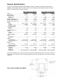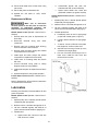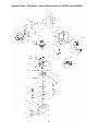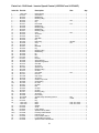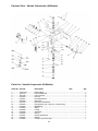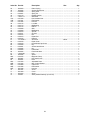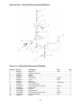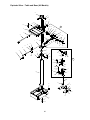
1
This .pdf document is bookmarked
Operating Instructions and Parts Manual
20-inch Variable Speed Drill Presses
Models: J-2221VS, J-2223VS, J-2232AC, J-2234AC
JET
427 New Sanford Road
LaVergne, Tennessee 37086
Ph.: 800-274-6848
www.jettools.com
Part No. M-354221
Revision D 03/2015
(ECR TW0135)
Copyright © 2015 JET
Warranty and Service
JET warrants every product it sells against manufacturers’ defects. If one of our tools needs service or repair, please
contact Technical Service by calling 1-800-274-6846, 8AM to 5PM CST, Monday through Friday.
Warranty Period
The general warranty lasts for the time period specified in the literature included with your product or on the official
JET branded website.
•
JET products carry a limited warranty which varies in duration based upon the product. (See chart below)
•
Accessories carry a limited warranty of one year from the date of receipt.
•
Consumable items are defined as expendable parts or accessories expected to become inoperable within a
reasonable amount of use and are covered by a 90 day limited warranty against manufacturer’s defects.
Who is Covered
This warranty covers only the initial purchaser of the product from the date of delivery.
What is Covered
This warranty covers any defects in workmanship or materials subject to the limitations stated below. This warranty
does not cover failures due directly or indirectly to misuse, abuse, negligence or accidents, normal wear-and-tear,
improper repair, alterations or lack of maintenance. JET woodworking machinery is designed to be used with Wood.
Use of these machines in the processing of metal, plastics, or other materials outside recommended guidelines may
void the warranty. The exceptions are acrylics and other natural items that are made specifically for wood turning.
Warranty Limitations
Woodworking products with a Five Year Warranty that are used for commercial or industrial purposes default to a
Two Year Warranty. Please contact Technical Service at 1-800-274-6846 for further clarification.
How to Get Technical Support
Please contact Technical Service by calling 1-800-274-6846. Please note that you will be asked to provide proof
of initial purchase when calling. If a product requires further inspection, the Technical Service representative will
explain and assist with any additional action needed. JET has Authorized Service Centers located throughout the
United States. For the name of an Authorized Service Center in your area call 1-800-274-6846 or use the Service
Center Locator on the JET website.
More Information
JET is constantly adding new products. For complete, up-to-date product information, check with your local distributor
or visit the JET website.
How State Law Applies
This warranty gives you specific legal rights, subject to applicable state law.
Limitations on This Warranty
JET LIMITS ALL IMPLIED WARRANTIES TO THE PERIOD OF THE LIMITED WARRANTY FOR EACH PRODUCT.
EXCEPT AS STATED HEREIN, ANY IMPLIED WARRANTIES OF MERCHANTABILITY AND FITNESS FOR A
PARTICULAR PURPOSE ARE EXCLUDED. SOME STATES DO NOT ALLOW LIMITATIONS ON HOW LONG AN
IMPLIED WARRANTY LASTS, SO THE ABOVE LIMITATION MAY NOT APPLY TO YOU.
JET SHALL IN NO EVENT BE LIABLE FOR DEATH, INJURIES TO PERSONS OR PROPERTY, OR FOR
INCIDENTAL, CONTINGENT, SPECIAL, OR CONSEQUENTIAL DAMAGES ARISING FROM THE USE OF OUR
PRODUCTS. SOME STATES DO NOT ALLOW THE EXCLUSION OR LIMITATION OF INCIDENTAL OR
CONSEQUENTIAL DAMAGES, SO THE ABOVE LIMITATION OR EXCLUSION MAY NOT APPLY TO YOU.
JET sells through distributors only. The specifications listed in JET printed materials and on official JET website are
given as general information and are not binding. JET reserves the right to effect at any time, without prior notice,
those alterations to parts, fittings, and accessory equipment which they may deem necessary for any reason
whatsoever. JET® branded products are not sold in Canada by JPW Industries, Inc.
Product Listing with Warranty Period
90 Days – Parts; Consumable items; Light-Duty Air Tools
1 Year – Motors; Machine Accessories; Heavy-Duty Air Tools; Pro-Duty Air Tools
2 Year – Metalworking Machinery; Electric Hoists, Electric Hoist Accessories; Woodworking Machinery used
for industrial or commercial purposes
5 Year – Woodworking Machinery
Limited Lifetime – JET Parallel clamps; VOLT Series Electric Hoists; Manual Hoists; Manual Hoist
Accessories; Shop Tools; Warehouse & Dock products; Hand Tools
NOTE: JET is a division of JPW Industries, Inc. References in this document to JET also apply to JPW Industries,
Inc., or any of its successors in interest to the JET brand.
2
Table of Contents
Section
Page
Warranty and Service ............................................................................................................................................ 2 Table of Contents .................................................................................................................................................. 3 Warning ................................................................................................................................................................. 4 Machinery General Safety Warnings .................................................................................................................... 4 General Electrical Cautions................................................................................................................................... 5 Safety Instructions for Drill Presses ...................................................................................................................... 6 Introduction ........................................................................................................................................................... 6 General Specifications .......................................................................................................................................... 7 Hole centers in Base (all models) ...................................................................................................................... 7 Operation and Set-Up ........................................................................................................................................... 8 Securing the Base ............................................................................................................................................. 8 Raising the Drill Head and Table ....................................................................................................................... 9 Electrical Connection ............................................................................................................................................ 9 Operating Controls .............................................................................................................................................. 10 Manual Speed Control (Models J-2221VS and J-2223VS) ............................................................................. 10 Inverter Speed Control (Models J-2232AC and J-2234AC) ............................................................................ 10 Depth Indicator — All Models .......................................................................................................................... 11 Maintenance ........................................................................................................................................................ 11 Replacement of Drive Belt ............................................................................................................................... 11 Replacement of Motor ..................................................................................................................................... 12 Lubrication........................................................................................................................................................... 12 Adjustments ........................................................................................................................................................ 13 Table Adjustment ............................................................................................................................................ 13 Radial Head Adjustment (All Models) .............................................................................................................. 13 Speed Pickup Adjustment (All Models) ........................................................................................................... 13 Operating Precautions ........................................................................................................................................ 13 Drilling Recommendations .................................................................................................................................. 14 Speeds for Drilling ........................................................................................................................................... 14 Feeds for Drilling ............................................................................................................................................. 14 Indication of Extreme Speeds and Feeds ....................................................................................................... 14 Speeds for High Speed Steel Drills ................................................................................................................. 14 Optional Equipment ............................................................................................................................................. 15 Coolant System Installation ............................................................................................................................. 15 Replacement Parts.............................................................................................................................................. 16 Exploded View – Drill Head – Manual Speed Control (J-2221VS and J-2223VS) .......................................... 17 Parts List – Drill Head – Manual Speed Control (J-2221VS and J-2223VS) ................................................... 18 Exploded View – Drill Head – Inverter Speed Control (J-2232AC and J-2234AC) ......................................... 20 Parts List – Drill Head – Inverter Speed Control (J-2232AC and J-2234AC) .................................................. 21 Exploded View – Spindle Components (All Models) ....................................................................................... 23 Parts List – Spindle Components (All Models) ................................................................................................ 23 Exploded View – Safety Shield Assembly (All Models) ................................................................................... 25 Parts List – Safety Shield Assembly (All Models) ............................................................................................ 25 Exploded View – Table and Base (All Models) ............................................................................................... 26 Parts List – Table and Base (All Models) ........................................................................................................ 27 Wiring Diagram – Models J-2221VS and J-2223VS ....................................................................................... 29 Wiring Diagram – Models J-2232AC and J-2234AC ....................................................................................... 30 3
Warning
- Misuse of this machine can cause serious
injury.
- For safety, machine must be set up, used and
serviced properly.
- Read, understand and follow instructions in
the Operating Instructions and Parts Manual
which was shipped with your machine.
- Never overreach—you may slip and fall.
When servicing machine:
- Always disconnect the machine from its
electrical supply while servicing.
- Always follow instructions in Operating
Instructions and Parts Manual when changing
accessory tools or parts.
- Never modify the machine without consulting
JET.
You—the stationary power tool user—hold the
key to safety.
When setting up machine:
- Always avoid using machine in damp or
poorly lighted work areas.
- Always be sure the machine support is
securely anchored to the floor or the work
bench.
Read and follow these simple rules for best results
and full benefits from your machine. Used properly,
JET machinery is among the best in design and
safety. However, any machine used improperly can
be rendered inefficient and unsafe. It is absolutely
mandatory that those who use our products be
properly trained in how to use them correctly. They
should read and understand the Operating
Instructions and Parts Manual as well as all labels
affixed to the machine. Failure in following all of
these warnings can cause serious injuries.
When using machine:
- Always wear safety glasses with side shields
(See ANSI Z87.1)
- Never wear loose clothing or jewelry.
Machinery General Safety Warnings
Always wear protective eye wear when
operating machinery. Eye wear shall be impact
resistant, protective safety glasses with side
shields which comply with ANSI Z87.1
specifications. Use of eye wear which does not
comply with ANSI Z87.1 specifications could
result in severe injury from breakage of eye
protection.
7.
Never leave the machine running while
unattended. Machine shall be shut off
whenever it is not in operation.
8.
Disconnect electrical power before servicing.
Whenever changing accessories or general
maintenance is done on the machine,
electrical power to the machine must be
disconnected before work is done.
2.
Wear proper apparel. No loose clothing or
jewelry which can get caught in moving parts.
Rubber soled footwear is recom-mended for
best footing.
9.
3.
Do not overreach. Failure to maintain proper
working position can cause you to fall into the
machine or cause your clothing to get caught,
pulling you into the machine.
Maintain all machine tools with care. Follow all
maintenance instructions for lubricating and
the changing of accessories. No attempt shall
be made to modify or have makeshift repairs
done to the machine. This not only voids the
warranty but also renders the machine unsafe.
1.
4.
Keep guards in place and in proper working
order. Do not operate the machine with guards
removed.
5.
Avoid dangerous working environments. Do
not use stationary machine tools in wet or
damp locations. Keep work areas clean and
well lit.
6.
10. Machinery must be anchored to the floor.
11. Secure work. Use clamps or a vise to hold
work, when practical. It is safer than using your
hands and it frees both hands to operate the
machine.
12. Never brush away chips while the machine is
in operation.
13. Keep work area clean. Cluttered areas invite
accidents.
Avoid accidental starts by being sure the start
switch is “OFF” before plugging in the
machine.
14. Remove adjusting keys and wrenches before
turning machine on.
4
15. Use the right tool. Don’t force a tool or
attachment to do a job for which it was not
designed.
18. All visitors should be kept at a safe distance
from the work area. Make workshop
completely safe by using padlocks, master
switches, or by removing starter keys.
16. Use only recommended accessories and
follow manufacturer’s instructions pertaining to
them.
19. Know the tool you are using — its application,
limitations, and potential hazards.
17. Keep hands in sight and clear of all moving
parts and cutting surfaces.
Familiarize yourself with the following safety notices used in this manual:
This means that if precautions are not heeded, it may result in minor injury and/or
possible machine damage.
This means that if precautions are not heeded, it may result in serious or even fatal
injury.
General Electrical Cautions
This drill press should be grounded in accordance with the National Electrical Code and local codes and
ordinances. This work should be done by a qualified electrician. The saw should be grounded to protect the
user from electrical shock.
Wire sizes
Caution: For circuits which are far away from the electrical service box, the wire size must be increased in
order to deliver ample voltage to the motor. To minimize power losses and to prevent motor overheating and
burnout, the use of wire sizes for branch circuits or electrical extension cords according to the following table is
recommended.
AWG (American Wire Gauge) number
Conductor Length
0-50 feet
50-100 feet
Over 100 feet
240 Volt lines
No. 14
No. 14
No. 12
5
120 Volt lines
No. 14
No. 12
No. 8
Safety Instructions for Drill Presses
5.
Keep hands in sight. Do not put hands or
fingers around, on, or below any rotating
cutting tools. Leather safety gloves should be
used when handling any sharp objects or
cutting tools. See Figure A.
6.
Always use the correct tooling. Tooling shall
always be maintained and properly sharpened.
All tooling must be run at the proper speeds
and feeds as they apply to the job. Use only
recommended accessories and follow those
manufacturer’s instructions pertaining to them.
Tooling shall not be forced in to any work
piece but fed according to the proper
specifications. Failure to follow these
instructions will not only ruin the tooling as well
as the machine, but can cause serious injury.
Always wear protective eye wear when
operating, servicing or adjusting machinery.
Eyewear shall be impact resistant, protective
safety glasses with side shields complying with
ANSI Z87.1 specifications. Use of eye wear
which does not comply with ANSI Z87.1
specifications could result in severe injury from
breakage of eye protection. Figure B.
7.
When drilling in material which causes dust, a
dust mask shall be worn. See Figure C.
8.
Avoid contact with coolant, especially guarding
the eyes.
9.
Never brush away any chips while the
machine is in operation. All clean up should be
done when the machine is stopped.
Non-slip footwear and safety shoes are
recommended. See Figure D.
10. Wear ear protectors (plugs or muffs) during
extended periods of operation. See Figure E.
1.
All work shall be secured using either clamps
or a vise to the drill press table. It is unsafe to
use your hands to hold any workpiece being
drilled.
2.
Drill press head and table shall be securely
locked to the column before operating the drill
press. This must always be checked prior to
starting the machine.
3.
4.
A
B
C
D
E
Introduction
This manual is provided by JET covering the safe operation and maintenance procedures for a JET 20-inch
Variable Speed Drill Press. This manual contains instructions on installation, safety precautions, general
operating procedures, maintenance instructions and parts breakdown. This machine has been designed and
constructed to provide years of trouble free operation if used in accordance with instructions set forth in this
manual. If there are any questions or comments, please contact either your local supplier or JET. JET can also
be reached at our web site: www.jettools.com.
6
General Specifications
The JET 20-inch Variable Speed Drill presses Models J-2221VS, J-2223VS, J-2232AC and J-2234AC are
available in manual speed control or inverter speed control configuration. Electrical power options are singlephase, 115 and 220 volts; or 3-phase, 440 volts.
Manual Speed Control Models
Inverter Speed Control Models
Model ................................................... J-2221VS................. J-2223VS ................... J-2232AC ................J-2234AC
Stock Number ........................................... 354221.....................354223 ....................... 354214 .................... 354216
Drilling Capacity:
Cast Iron (in.) ............................................ 1-1/4........................ 1-1/4 ........................... 1-1/2 ....................... 1-1/2
Steel (in.) ....................................................... 1.............................. 1 ........................... 1-3/8 ....................... 1-3/8
Spindle to Table Max. (in.) .......................... 30-1/4...................... 30-1/4 ......................... 30-1/4 ..................... 30-1/4
Spindle to Base Max. (in.) ........................... 44-1/2...................... 44-1/2 ......................... 44-1/2 ..................... 44-1/2
Spindle to Column Max. (in.) ..................... 10-7/16.................... 10-7/16 ....................... 10-7/16 ....................10-7/16
Motor:
Rating........................................ 2HP, 1-Phase........... 2HP, 3-Phase ..............2HP, 3-Phase .......... 2HP, 3-Phase
Voltage ............................................. 115/220V................. 220/440V ........................... 220V ....................... 440V
Pre-wired Voltage ....................................115V........................ 220V ........................... 220V ....................... 440V
T-Slots (Table/Base):
Number ......................................................... 2.............................. 2 ................................. 2 ............................. 2
Size (in.) ..................................................... 5/8........................... 5/8 .............................. 5/8 .......................... 5/8
Column Diameter (in.) ................................... 4-1/2........................ 4-1/2 ........................... 4-1/2 ....................... 4-1/2
Spindle:
Travel (in.) ..................................................... 6.............................. 6 ................................. 6 ............................. 6
Taper....................................................... MT-3........................ MT-3 ........................... MT-3 ....................... MT-3
RPM (variable) .................................. 300-2000..................300-2000 ...................... 65-2000 ...................65-2000
Quill:
Diameter (in.) ................................................. 3.............................. 3 ................................. 3 ............................. 3
Travel (in.) ..................................................... 6.............................. 6 ................................. 6 ............................. 6
Table:
Overall Size (in.) ............................ 22 x 18-3/4............... 22 x 18-3/4 .................. 22 x 18-3/4 .............. 22 x 18-3/4
Working Surface (in.)................. 18-1/8 x 14-3/4......... 18-1/8 x 14-3/4 ............ 18-1/8 x 14-3/4 ........ 18-1/8 x 14-3/4
Travel (in.) ................................................... 18............................ 18 ............................... 18 ........................... 18
Base:
Overall Size (in.) .................................. 26 x 19..................... 26 x 19 ........................26 x 19 .................... 26 x 19
Working Surface (in.)............... 15-1/4 x 12-1/16....... 15-1/4 x 12-1/16 .......... 15-1/4 x 12-1/16 ...... 15-1/4 x 12-1/16
Overall Dimensions:
Length (in.) ............................................ 34-1/4...................... 34-1/4 ......................... 36-5/8 ..................... 36-5/8
Width (in.) .................................................... 27............................ 27 ............................... 27 ........................... 27
Height (in.) ................................................... 78............................ 78 ............................... 78 ........................... 78
Net Weight........................... 715 lbs.(325 kgs.)..... 715 lbs.(325 kgs.) ........ 792 lbs.(325 kgs.) .... 792 lbs.(325 kgs.)
The above specifications were current at the time this manual was published, but because of our policy of continuous
improvement, JET reserves the right to change specifications at any time and without prior notice, without incurring
obligations.
Hole centers in Base (all models)
7
The JET Model J-2221VS and J-2223VS drill
presses feature manual speed control. Models J2232AC and J-2234AC have inverter speed
control. This manual contains procedures for both
speed control versions. The manual provides
separate instructions when differences in operation
and maintenance exist.
Operation and Set-Up
Securing the Base
The base of the drill press has four mounting slots;
two slots on both sides of the base. The drill press
should be level and rest solidly on the floor. Place
shims under the four mounting slots in the base as
needed to level the drill press.
Refer to Figures 1 and 2 for key features of the drill
press.
When securing the base to the floor, apply even
torque to the fasteners to prevent distortion of the
base.
Figure 1
Drill Press Features
(Manual Speed Control Model)
Figure 2
Drill Press Features
(Inverter Speed Control Model)
8
Raising the Drill Head and Table
Slide a grommet onto the cord to be installed later
in the control box hole, to prevent stress to the
power cord.
The drill press is shipped with the table and drill
head supported by wooden blocks near the bottom
of the column.
The head is raised to the operating position using a
strap and hoist, then secured to the column by
tightening the hex cap screw. The table is raised to
the desired position using the crank handle. See
Adjustments section for more information.
1.
Bring the lead wires through the hole in the
side of the control box and connect as follows
(refer to Figure 3a):
2.
If your incoming power is single phase,
connect the two leads to L1 and L2, and the
green ground wire to the grounding screw.
Electrical Connection
Electrical connections must
be made by a qualified electrician in
compliance with all relevant codes. This
machine must be properly grounded to help
prevent electrical shock and possible fatal
injury.
L1 L2 L3
Refer to the Wiring Diagram section for wiring
information.
Grounding
Screw
The Drill Press is not supplied with a power cord.
To connect power, you may either install a power
cord with a UL/CSA listed plug, or hard wire the
machine directly to a service panel.
If the drill press is to be hard-wired to a panel,
make sure a disconnect is available for the
operator. (During hard-wiring of the machine, make
sure the fuses have been removed or the breakers
have been tripped in the circuit to which the drill
press will be connected.)
Figure 3a
Manual control models: Model J-2221VS (1Phase) is pre-wired for 110 volts. Model J-2223VS
(3-Phase) is pre-wired for 220 volts.
3.
If your incoming power is three phase,
connect the three leads to L1, L2 and L3, and
the green ground wire to the grounding screw.
NOTE: If rewiring the J-2221VS or J-2223VS for
alternate voltage, you must reconnect the wire on
the LED display accordingly (Figure 3), in addition
to changing the motor leads.
This drill press must be properly grounded.
Make sure the green ground wire is secured to the
grounding screw as described.
Make sure the power available matches the power
requirement of the drill. When the drill is connected
properly, the spindle turns clockwise in a
conventional drilling rotation. If the spindle does not
turn clockwise, disconnect the drill from the power
supply and reverse two of the three power leads
(except ground wire green).
Figure 3
Inverter control models: Model J-2232AC (3Phase) is pre-wired for 220 volt only. The machine
can also be run on 1-Phase power by hooking up
the ground, L1 and L2 wires, as explained below.
Model J-2234AC (3-Phase) is pre-wired for 440
volt only.
To wire the drill press with inverter control:
If using a power cord, strip back the cord until
about 3 to 4 inches of the lead wires are exposed.
9
Operating Controls
To avoid damage to the speed
adjustment mechanism, the drive motor must
be operating before attempting to adjust the
speed setting.
Manual Speed Control (Models J2221VS and J-2223VS)
A speed shift lever is on the right side of the head
(refer to Figure 2 for location). The handle is turned
clockwise to increase spindle speed and
counterclockwise to reduce speed.
Refer to Figure 4.
Spindle Selector Switch
A three-position selector switch is provided at the
left side of the drill head. It is used to select spindle
rotation: reverse (REV), off (OFF), and forward
(FWD).
Front Panel
The front panel (Figure 5) is mounted on the front
of the drill head. The panel contains all the controls
required to operate the drill press. There are
additional controls on the inverter mounted on the
left side of the drill head. The inverter is preprogrammed at the factory and the settings are not
to be changed!
Speed Control Hand Wheel
To avoid damage to the speed
adjustment mechanism, the drive motor must
be operating before attempting to adjust the
speed setting.
A speed control hand wheel is provided on the left
front of the head (Figure 4). The handle is turned
clockwise to increase spindle speed and
counterclockwise to reduce speed. To set the
speed, the speed control handle is turned until the
pointer on the front panel is at the desired speed.
Speed Indicator
An LED spindle speed indicator is provided on the
front panel. The LED indicates speeds from 300 to
2000 rpm.
A selector switch is provided at the left side of the
drill head. The two-position switch is used to start
and stop the drive motor.
Figure 5
Control Panel (Inverter Control)
Inverter On Indicator
The INVERTER ON light indicates that the inverter
is powered up.
Spindle On Pushbutton Switch
The SPINDLE ON pushbutton is used to start the
drive motor. To stop the motor, the pushbutton is
pressed (the switch toggles on and off).
Figure 4
Control Panel (Manual Speed Control)
Emergency Stop Pushbutton Switch
The mushroom shaped EMG. STOP pushbutton
switch provides a quick means of stopping the
drive motor. To reset the pushbutton switch, the
knob is turned clockwise (as shown on the face of
the knob).
Inverter Speed Control (Models J2232AC and J-2234AC)
Speed Shift Lever
10
RPM Display
Maintenance
The spindle speed display shows the spindle RPM
selected by the speed control knob.
Replacement of Drive Belt
Spindle Speed Knob
Make sure to disconnect
electrical power to the drill press to avoid the
possibility of inadvertent operation and
exposure to potentially lethal voltage levels.
The SPINDLE SPEED knob is used to set the
desired spindle speed (clockwise increases).
Spindle Selector
The SPINDLE selector switch is used to set the
desired direction of spindle rotation. The REV.
(reverse) setting will provide counterclockwise
rotation. The FOR. setting will provide clockwise
rotation.
Manual Speed Control (Models J-2221VS and J2223VS)
Drilling Speed Chart
A DRILLING SPEED CHART is provided on the
front panel. The chart can be used to select the
speed required for various drill sizes (0.196 inch to
1.000 inch — 5 mm to 25 mm) and materials (steel,
cast iron, aluminum, and copper). The chart
defines spindle speeds from 300 to 2000 RPM.
1.
Start drill press. Set speed control to highest
speed. Stop drill press.
2.
Disconnect electrical power by setting drill
press circuit breaker to OFF.
3.
Remove head cover.
4.
Remove belt. (With speed control setting at the
highest speed, the belt should be loose
enough to remove.)
5.
Install the replacement belt. Install the head
cover.
6.
Set the drill press circuit breaker ON.
7.
Operate the drill press to verify correct
operation.
Depth Indicator — All Models
Refer to Figure 6.
Inverter Speed Control (Models J-2232AC and J2234AC)
1.
Disconnect electrical power by setting drill
press circuit breaker to OFF.
2.
Remove pan screws from small cover (around
column). Remove pan screws and eight bolts
from head cover.
3.
Loosen set screw and remove shift lever.
4.
Remove plastic spindle cup.
5.
Remove head cover. Leave small cover in
place.
6.
Disconnect electrical wiring from motor
junction box. Remove motor from mounting
plate.
7.
Remove motor mounting plate.
8.
Remove three screws from pulley covers
(discs). Remove used belt. Install the
replacement belt.
9.
Install pulley covers and secure with three
screws in each pulley cover.
Figure 6
A drilling depth indicator is provided on the front of
the drill head. The indicator can be set for depths
up to 6.5 inches (16.5 mm). A knurled knob is
provided at the front, underside of the head. Before
starting the motor, set the end of the drill against
the surface into which the hole is to be drilled. The
indicator is zeroed out using the knurled knob. The
motor is started and the hole drilled until the
indicator pointer reaches the desired depth.
10. Install motor mounting plate. Install motor and
connect electrical wiring (refer to Wiring
Diagram section for wiring details).
11. Install the head cover and secure with pan
screws and eight bolts.
11
12. Secure small head cover to head cover using
pan screws.
b.
Countershaft spindle and push rod:
Lubricate with SAE 20 oil occasionally.
13. Set the drill press circuit breaker ON.
c.
Speed control handle cam: Clean and
grease with medium cup grease annually.
14. Operate the drill press to verify correct
operation.
Inverter Speed Control (Models J-2232AC and J2234AC)
Replacement of Motor
Make sure to disconnect
electrical power to the drill press to avoid the
possibility of inadvertent operation and
exposure to potentially lethal voltage levels.
Manual Speed Control (Models J-2221VS and J2223VS)
1.
Remove drive belt (refer to Replacement Of
Drive Belt).
2.
Disconnect electrical
junction box.
3.
Remove nuts from mounting studs securing
motor to drill head. Remove motor.
4.
Remove upper and lower pulleys and related
components from motor shaft.
5.
Install upper and lower pulleys and related
components on replacement motor shaft.
6.
Install motor on mounting studs and secure
with nuts.
7.
Connect electrical wiring (refer to Wiring
Diagram section for wiring details).
8.
Install drive belt (refer to Replacement Of Drive
Belt).
9.
Operate drill press to verify proper operation.
wiring
from
1.
Spindle pulley drive: Lubricate spindle splines
occasionally with light grease.
2.
Quill and column: Lubricate with light film of oil.
3.
Lift rack: Lubricate regularly with SAE 20 oil
(clean rack with kerosene before applying oil).
4.
Variable speed drive:
a.
Periodically check oil level in sight gauge
on (left side of head) (refer to Figure 7).
b.
If level is below centerline of sight gauge,
add oil.
c.
To add oil, remove oil fill tube cover plate.
Pull fill tube out of hole in head cover.
d.
Add SAE 20 oil to bring oil level up to the
centerline of the sight gauge.
e.
Put end of fill tube back through hole in
head cover. Install fill tube cover and
secure with two screws.
motor
Inverter Speed Control (Models J-2232AC and J2234AC)
Refer to Replacement Of Drive Belt for instructions
on removal of the drive motor.
Lubrication
Following are lubrication recommendations for drill
press components.
Figure 7
Manual Speed Control (Models J-2221VS and J2223VS)
1.
Spindle pulley drive: Lubricate spindle splines
occasionally with light grease.
2.
Quill and column: Lubricate with light film of oil.
3.
Lift rack: Lubricate regularly with SAE 20 oil
(clean rack with kerosene before applying oil).
4.
Variable drive:
a.
Speed control fork: service oil hole with
SAE 20 oil once a week.
12
3.
Adjustments
Operate drill press to verify that speed readout
is operating correctly.
Table Adjustment
Operating Precautions
Refer to Figure 8.
The following operating and safety precautions
must be observed in order to avoid harm to the
operator or damage to the drill press.
The table can be raised or lowered to
accommodate the height of the workpiece. To raise
or lower the table, loosen the table lock using the
hand crank. Then use the hand crank to move the
table to the desired height. Then lock the table in
position.
Figure 8
1.
The head assembly must be locked to the
column so the thrust produced by drilling will
not force the head assembly up the column.
2.
The work table must be locked to the column
so it will not be forced down the column.
3.
Before drilling, release the quill lock nut to
permit free travel of the quill.
4.
Be sure the belt is tightened to the proper
tension.
5.
DO NOT start to drill the workpiece until
making certain the workpiece is held down
securely.
6.
MAKE SURE THE DRIVE MOTOR IS
RUNNING BEFORE turning the speed control
handwheel in either direction.
7.
Point of operation protection is required for
maximum safety.
This remains the
responsibility of the user/purchaser since
conditions differ between jobs.
8.
Make sure the drill is secured in the spindle or
chuck before attempting to use the drill press.
9.
Make sure the spindle taper is clean and free
of burrs, scoring, and galling to assure
maximum gripping.
Radial Head Adjustment (All Models)
Change the radial position of
the drill head only if the drill press base is
secured to the floor. Swinging the drill head
without the base being secured to the floor will
cause the drill press to become unstable and
tip over resulting in injury and/or damage to the
machine.
10. Lock the quill in position when using any sideloaded tool.
The radial position of the drill head can be changed
to accommodate the drilling of a hole that may be
offset from the center of the table. Reposition the
drill head as follows:
1.
Loosen the two clamping hex nuts using the
hex socket wrench provided with the machine.
2.
The swing the drill head to the desired
position.
3.
Tighten the two clamping nuts.
Speed Pickup Adjustment (All Models)
1.
Loosen screws securing speed pickup (ref.
68A, page 23) to plate (ref. 69A, page 23).
2.
Adjust the speed pickup gap to approximately
1/8-inch. Re-tighten screws.
13
Indication of Extreme Speeds and
Feeds
Drilling Recommendations
A drill that splits up the web is evidence of too
much feed or insufficient tip clearance at the center
as a result of improper grinding. The rapid wearing
away of the extreme outer corners of the cutting
edges indicates that the speed is too high. A drill
chipping or braking out at the cutting edges
indicates that either the feed is too heavy or the
drill has been ground with too much tip clearance.
Speeds for Drilling
The speed of a drill is usually measured in terms of
the rate at which the outer periphery of the tool
moves in relation to the work being drilled. The
common term for this is Surface Feet per Minute
(SFM). The relationship of SFM is expressed in the
following formulas:
Speeds for High Speed Steel Drills
SFM = 0.26 X rpm X Drill Diameter (in inches)
Material
RPM = 3.8 x ________SFM__________
Drill diameter (in inches)
Alloy Steel — 300 to 400 Brinell ................ 20 - 30
Stainless Steel .......................................... 30 - 40
Automotive Steel Forgings ........................ 40 - 50
Tool Steel, 1.2C ........................................ 50 - 60
Steel, .4C to .5C........................................ 70 - 80
Mild Machinery Steel, .2C to .3C ............. 80 - 110
Hard Chilled Cast Iron ............................... 30 - 40
Medium Hard Cast Iron ........................... 70 - 100
Soft Cast Iron ........................................ 100 - 150
Malleable Iron ........................................... 80 - 90
High Nickel Steel or Monel ........................ 40 - 50
High Tensile Bronze ................................. 70 -150
Ordinary Brass and Bronze ................... 200 - 300
Aluminum and its Alloys ........................ 200 - 300
Magnesium and its Alloys...................... 250 - 400
Slate, Marble, and Stone ............................ 15 -25
Plastics and similar material (Bakelite) .. 100 - 150
Wood ..................................................... 300 -400
Titanium Alloys.......................................... 10 - 25
Titanium Alloy Sheet ................................. 50 - 60
In general, the higher the speed the shorter the drill
life. Operating at the low end of the speed range
for a particular material will result in longer life. The
most efficient speed for operating a drill depends
on many variables:
1.
2.
3.
4.
5.
6.
Speed
In SFPM
Composition and hardness of material.
Depth of the hole.
Efficiency of the cutting fluid.
Type and condition of the drilling machine.
Desired quality of the hole.
Difficulty of set-up.
Feeds for Drilling
The feed of a drill is governed by the size of the
tool and the material drilled. Because the feed rate
partially determines the rate of production and also
is a factor in tool life, it should be chosen carefully
for each job. In general, the most effective feeds
will be found in the following ranges:
In cases where carbon steel drills are applicable,
the drill should be run at speeds of from 40 to 50
percent of those given above.
Diameter of Drill
Feed per Revolution
(inches)
(inches)
Under 1/8 .................... 0.001 to 0.002
1/8 to 1/4 ..................... 0.002 to 0.004
1/4 to 1/2 ..................... 0.004 to 0.007
1/2 to 5/8 ..................... 0.007 to 0.015
14
Optional Equipment
Coolant System Installation
1.
Remove the large reservoir cover plate from
the machine base. Tap 1/4-20 threads in the 4
pilot holes.
2.
Install the cover plate back onto the machine
base.
3.
Insert the pump into the opening, utilize the
screws from the small round cover plate to
fasten the pump to the base.
4.
Position the power switch and valve bracket on
the spindle casting. Mark mounting hole
locations and drill holes. (Refer to Figure 8)
Install the 3/8-inch hose coupling to the
coolant pump. If needed, apply a light coat of
pipe sealant or thread seal tape to the threads
to prevent leakage.
7.
Mount the flow valve to the bracket, connect
the supply hose to the pump and valve, use
hose clamps at the ends.
8.
Install the flexible nozzle to the flow valve.
9.
Install the 1/2-inch hose coupler to the
worktable, and seal threads if needed.
Connect the return hose.
10. Connect the power cord to a suitable source
and ground (refer to General Electrical
Cautions).
Note: Mount components near the lower edge
of the spindle casting. Do not mount
components above the line shown in Figure 9.
5.
6.
11. Fill the reservoir with appropriate machining
coolant.
Install the power switch and valve bracket with
the provided fastener hardware.
15
Troubleshooting
Trouble
Spindle does not turn.
Spindle noisy.
Drill stalls.
Poorly drilled holes.
Motor overheating.
Table cannot be raised.
No speed readout.
Probable Cause
Remedy
Motor overload protector tripped.
Press motor overload reset button.
Circuit breaker tripped.
Reset circuit breaker.
Branch circuit breaker tripped or fuse
blown.
Reset branch circuit breaker/replace fuse.
Open wire in switch circuit.
Repair open circuit.
Defective switch.
Replace switch.
Broken drive belt.
Replace drive belt.
Damaged spindle bearings.
Replace bearings.
Worn spline.
Replace spline.
Worn drive belt.
Check condition of belt. Replace if glazed
or slipping on pulleys.
Excessive feed rate for size of drill and
material being drilled. No cutting fluid or
improper cutting fluid.
Reduce feed pressure or use cutting fluid.
Use correct cutting fluid.
Drill dull.
Sharpen drill.
Lack of rigidity in hold-down method.
Check that all T-slot hold-downs are tight
and that table-lock and drill head bolts are
tight.
Speed too fast for material and drill size.
Check spindle speed recommendations.
Reduce speed if necessary.
Feed too fast for material and drill size.
Reduce feed rate.
No or improper cutting fluid or coolant
being used.
Use cutting fluid, or change to proper fluid
or coolant for material being drilled.
Improperly ground drill bit.
Check for proper angles and reliefs.
Regrind to proper geometry.
Electrical circuit fault.
Check current draw in circuit. Make sure
current draw is the same as rating on
motor plate.
Oversize drill.
Reduce drill size.
Excessive feed.
Reduce feed rate.
No cutting fluid, or wrong fluid.
Use correct cutting fluid for the material
and drill.
Lack of lubrication.
Lubricate.
Speed pickup out of adjustment or failed.
Adjust gap between speed pickup and
post spindle pulley. If there is no readout
on the LED speed indicator after adjusting
the gap, replace the speed pickup.
Replacement Parts
Replacement parts are listed on the following pages. To order parts or reach our service department, call 1800-274-6848, Monday through Friday (see our website for business hours, www.jettools.com). Having the
Model Number and Serial Number of your machine available when you call will allow us to serve you quickly
and accurately.
16
Exploded View – Drill Head – Manual Speed Control (J-2221VS and J-2223VS)
78
84
81
79
88
86A
83
87
91
86B
81B
81A
60
96
81C
76
50
82
85
77
60C
60D
60B
50
59
57
58
47
60A
42
50
56
66
48
43
54
52
63A
65
62
61
90
89
44
53
45
55
51
41
46
49
93
33
39
40
67
39
35
14
92
94
34
37
32
11
13
12
10
26
38
36
64A
11A
30
9
11B
8
15
16
17
18
29
19
28
7
21
27
20
22
23
24
25
17
95
80A
80
80C
80B
Parts List – Drill Head – Manual Speed Control (J-2221VS and J-2223VS)
Index No. Part No.
Description
Size
Qty
7 ................ 5510077 .................... Spindle Step Pulley.................................................. ...................................... 1
8 ................ 5510078 .................... Spindle Nut .............................................................. ...................................... 1
9 ................ 5510079 .................... V-Belt ....................................................................... ...................................... 1
10 .............. 5510080 .................... VS Lower Spindle Pulley ......................................... ...................................... 1
11 .............. 5510081 .................... VS Upper Spindle Pulley ......................................... ...................................... 1
11A ............ 5513673 .................... Cap Screw ............................................................... ...................................... 1
11B ............ 5513674 .................... Hex Nut .................................................................... ...................................... 4
12 .............. 5510082 .................... Ball Bearing ............................................................. ...................................... 1
13 .............. 5510083 .................... Bearing Cover .......................................................... ...................................... 1
14 .............. 5510084 .................... Speed Change Lever ............................................... ...................................... 1
15 .............. 5510085 .................... Ball Bearing ............................................................. ...................................... 2
16 .............. 5510086 .................... Bushing .................................................................... ...................................... 1
17 .............. 5510087 .................... Bushing .................................................................... ...................................... 1
18 .............. 5510088 .................... Hex Bolt ................................................................... ...................................... 4
19 .............. 5510089 .................... Washer .................................................................... ...................................... 4
20 .............. 5510090 .................... Bearing Housing ...................................................... ...................................... 1
21 .............. 5510091 .................... Set Screw ................................................................ ...................................... 1
22 .............. 5510092 .................... Spindle Mid Shaft..................................................... ...................................... 1
23 .............. 5510093 .................... Key........................................................................... ...................................... 1
24 .............. 5510094 .................... Key........................................................................... ...................................... 1
25 .............. 5510095 .................... C-Ring (Shaft) .......................................................... ...................................... 1
26 .............. 5510096 .................... Variable Speed Belt ................................................. ...................................... 1
27 .............. 5510097 .................... C-Ring (Shaft) .......................................................... ...................................... 2
28 .............. 5510098 .................... Spring Cover ............................................................ ...................................... 1
29 .............. 5510099 .................... Spring ...................................................................... ...................................... 1
30 .............. 5510100 .................... VS Lower Motor Pulley ............................................ ...................................... 1
32 .............. 5510102 .................... Key........................................................................... ...................................... 1
33 .............. 5510103 .................... VS Upper Motor Pulley ............................................ ...................................... 1
34 .............. 5510104 .................... Set Screw ................................................................ ...................................... 1
35 .............. 5510105 .................... Speed Change Bracket............................................ ...................................... 1
36 .............. 5510106 .................... Link .......................................................................... ...................................... 1
37 .............. 5510107 .................... Shaft ........................................................................ ...................................... 1
38 .............. 5510108 .................... C-Ring (Shaft) .......................................................... ...................................... 1
39 .............. 5510109 .................... C-Ring (Hole) ........................................................... ...................................... 1
40 .............. 5510110 .................... Ball Bearing ............................................................. ...................................... 2
41 .............. 5510111 .................... Nut ........................................................................... ...................................... 2
42 .............. 5512114 .................... Control Rod Sleeve.................................................. ...................................... 1
43 .............. 5512115 .................... Control Rod.............................................................. ...................................... 1
44 .............. 5510114 .................... Pin Spring ................................................................ ...................................... 1
45 .............. 5510115 .................... Pin............................................................................ ...................................... 1
46 .............. 5510116 .................... Roller ....................................................................... ...................................... 1
47 .............. 5510117 .................... Hex Nut .................................................................... ...................................... 1
48 .............. 5512116 .................... Housing.................................................................... ...................................... 1
49 .............. 5513675 .................... Cap Screw ............................................................... M8x35 ........................... 2
50 .............. 5513676 .................... Pan Head Screw...................................................... ...................................... 6
51 .............. 5510121 .................... Helix Gear ................................................................ ...................................... 1
52 .............. 5510122 .................... Worm Gear .............................................................. ...................................... 1
53 .............. 5510123 .................... Thrust Bearing ......................................................... ...................................... 1
54 .............. 5510124 .................... Bushing .................................................................... ..................................... 1
55 .............. 5513677 .................... Set Screw ................................................................ ...................................... 1
56 .............. 5510126 .................... Hand Wheel (includes #58) ..................................... ...................................... 1
57 .............. 5510127 .................... Retaining Ring ......................................................... ...................................... 1
58 .............. 5510126 .................... Hand Grip ................................................................ ...................................... 1
59 .............. 5510129 .................... Set Screw ................................................................ ...................................... 1
60 .............. J-5513678 ................. Pulley Cover Assembly (incl 60A,60B,60C,60D) ..... ...................................... 1
60A ............ J-5513679 ................. Nameplate Bracket .................................................. ...................................... 1
60B ............ J-5513680 ................. Cover Plate .............................................................. ...................................... 1
60C............ 5513681 .................... Cap Screw ............................................................... ...................................... 2
60D............ J-5513682 ................. Plate Bracket ........................................................... ...................................... 1
18
Index No. Part No.
Description
Size
Qty
61 .............. 5510131 .................... Thrust Bearing ......................................................... ...................................... 1
62 .............. 5510132 .................... Shaft ........................................................................ ...................................... 1
63A ............ 5513683 .................... Cap Screw ............................................................... ...................................... 2
64A ............ 5513519 .................... LED Display ............................................................ 115/230/24V.................. 1
.................. 5513736 .................... LED Display ............................................................ 220/440 ......................... 1
65 .............. 5513690 .................... Face Plate................................................................ ...................................... 1
66 .............. 5513685 .................... C-Ring (Hole) ........................................................... ...................................... 1
67 .............. 5510137 .................... Round Head Screw.................................................. ...................................... 4
76 .............. 5511848 .................... Knob ........................................................................ ...................................... 1
77 .............. 5514634 .................... Set Screw ................................................................ M3x8 ............................. 1
78 .............. 5511849 .................... Cover ....................................................................... ...................................... 1
79 .............. 5513354 .................... Screw....................................................................... ...................................... 2
80 .............. J-5510344 ................. Motor........................................................................ 2HP 1PH 115/220V....... 1
.................. 5510345 .................... Motor........................................................................ 2HP 3PH 220/440V....... 1
80A ............ 5517320 .................... Square Key .............................................................. ...................................... 1
80B ............ 5517321 .................... Flat Washer ............................................................. ...................................... 4
80C............ 5517322 .................... Hex Nut .................................................................... ...................................... 4
81 .............. 5517323 .................... Fwd/Rev Switch ....................................................... 1 Phase ......................... 1
.................. 5517331 .................... Fwd/Rev Switch ....................................................... 3 Phase ......................... 1
81A ............ 5517324 .................... Switch Plate ............................................................. ...................................... 1
81B ............ 5517325 .................... Label ........................................................................ ...................................... 1
81C............ 5517326 .................... Label Cover ............................................................. ...................................... 1
82 .............. 5513356 .................... Switch Box ............................................................... ...................................... 1
83 .............. 5513357 .................... Screw....................................................................... ...................................... 2
84 .............. 5513358 .................... Hex Nut .................................................................... ...................................... 4
85 .............. 5513359 .................... Screw....................................................................... ...................................... 4
86A ............ 5517327 .................... Strain Relief ............................................................. ...................................... 2
86B ............ 5517328 .................... Hex Nut .................................................................... ...................................... 2
87 .............. 5517329 .................... Connection Cord ...................................................... ...................................... 1
88 .............. 5517330 .................... Power Cord.............................................................. ...................................... 1
89 .............. 5513935 .................... VS Spindle Pulley Assembly.................................... ...................................... 1
90 .............. 5513934 .................... VS Motor Pulley Assembly ...................................... ...................................... 1
91 .............. 5513355 .................... Switch Assembly (includes items 76-79,81-85) ....... 1 Phase ......................... 1
.................. 5514716 .................... Switch Assembly (includes items 76-79,81-85) ....... 3 Phase ......................... 1
92 .............. 2221VS-92 ................ Bushing .................................................................... ...................................... 1
93 .............. TS-1503041 .............. Socket Head Cap Screw.......................................... M6 x 16 ......................... 2
94 .............. TS-1524021 .............. Set Screw ................................................................ M8 x 10 ......................... 1
95 .............. 2221VS-95 ................ Key........................................................................... 5 x 20 mm ..................... 1
96 .............. 5515285 .................... Spindle Cap ............................................................. ...................................... 1
19
Exploded View – Drill Head – Inverter Speed Control (J-2232AC and J-2234AC)
20
Parts List – Drill Head – Inverter Speed Control (J-2232AC and J-2234AC)
Index No. Part No.
Description
Size
Qty
1 ................ J-5517332 .................. Head Casting ............................................................ ...................................... 1
2 ................ 5510142 ..................... Oil Window ............................................................... ...................................... 1
3 ................ 5510143 ..................... Ball Bearing .............................................................. ...................................... 1
4 ................ 5510144 ..................... Retaining Ring .......................................................... ...................................... 1
5 ................ 5510145 ..................... Gear ......................................................................... 32T ................................ 1
6 ................ 5510146 ..................... Key ........................................................................... ...................................... 1
7 ................ 5510147 ..................... Drive Shaft ................................................................ 13T ................................ 1
8 ................ 5510148 ..................... Ball Bearing .............................................................. ...................................... 1
9 ................ 5510149 ..................... Retaining Ring .......................................................... ...................................... 1
10 .............. 5510150 ..................... Ball Bearing .............................................................. ...................................... 1
11 .............. 5510151 ..................... Retaining Ring .......................................................... ...................................... 1
12 .............. 5510153 ..................... Gear ......................................................................... 55T ................................ 1
13 .............. 5510152 ..................... Set Screw ................................................................. ...................................... 1
14 .............. 5510155 ..................... Spring ....................................................................... ...................................... 1
15 .............. 5510154 ..................... Steel Ball .................................................................. ...................................... 1
16 .............. 5510159 ..................... Key ........................................................................... ...................................... 1
17 .............. 5517333 ..................... Drain Plug ................................................................. 3/8 NPT ......................... 1
18 .............. 5510158 ..................... Gear ......................................................................... 18T ................................ 1
20 .............. 5510160 ..................... Key ........................................................................... ...................................... 1
21 .............. 5510161 ..................... Mid Shaft .................................................................. ...................................... 1
22 .............. 5510162 ..................... Key ........................................................................... ...................................... 1
23 .............. 5510163 ..................... Retaining Ring .......................................................... ...................................... 2
24 .............. 5510164 ..................... Ball Bearing .............................................................. ...................................... 1
25 .............. 5510165 ..................... Pin ............................................................................ ...................................... 1
26 .............. 5510166 ..................... Bar ........................................................................... ...................................... 1
26-1 ........... 5517334 ..................... Ring.......................................................................... ...................................... 1
27 .............. 5510167 ..................... Hex Nut .................................................................... ...................................... 1
28 .............. 5510168 ..................... Spring Washer .......................................................... ...................................... 1
29 .............. 5510169 ..................... Speed Change Block................................................. ...................................... 1
30 .............. 5510170 ..................... Gear Bar ................................................................... ...................................... 1
31 .............. 5510171 ..................... Set Screw ................................................................. ...................................... 1
32 .............. 5517335 ..................... Speed Lever ............................................................. ...................................... 1
33 .............. 5517336 ..................... Retaining Ring .......................................................... ...................................... 1
34 .............. 5510173 ..................... Oil Seal ..................................................................... ...................................... 1
35 .............. 5510177 ..................... Gear Shaft ................................................................ 18T ................................ 1
36 .............. 5517337 ..................... Hex Nut .................................................................... ...................................... 1
37 .............. 5517338 ..................... Cap Screw ................................................................ ...................................... 1
38 .............. 5510178 ..................... Set Screw ................................................................. ...................................... 1
39 .............. 5517339 ..................... Gearbox Top Cover ................................................... ...................................... 1
40 .............. 5510180 ..................... Oil Fill Fitting ............................................................. ...................................... 1
40-1 ........... 5517340 ..................... Fill Tube.................................................................... ...................................... 1
41 .............. 5510181 ..................... Oil Seal ..................................................................... ...................................... 1
42 .............. 5510182 ..................... Bolt ........................................................................... ...................................... 1
43 .............. 5510183 ..................... Oil Seal ..................................................................... ...................................... 1
44 .............. 5510184 ..................... Oil Seal ..................................................................... ...................................... 1
44-1 ........... 5517341 ..................... Retaining Ring .......................................................... ...................................... 1
45 .............. 5510185 ..................... Set Screw ................................................................. ...................................... 1
46 .............. 5510186 ..................... Drive Pulley............................................................... ...................................... 1
47 .............. 5517342N .................. Spindle Pulley with Driving Sleeve ............................. 48T ................................ 1
48 .............. 5517343 ..................... Belt ........................................................................... 720x8............................. 1
52 .............. 5510192 ..................... Key ........................................................................... ...................................... 1
53 .............. J-5517349 .................. Motor ........................................................................ 2HP, 3PH, 220V ............. 1
.................. J-5517350 .................. Motor ........................................................................ 2HP, 3PH, 440V ............. 1
54 .............. 5510194 ..................... Washer ..................................................................... ...................................... 4
55 .............. 5510195 ..................... Screw ....................................................................... ...................................... 4
56 .............. 5510204 ..................... E-stop Switch ............................................................ ...................................... 1
56-1 ........... 5510197 ..................... Speed Proximity Switch ............................................. ...................................... 1
56-2 ........... 5510198 ..................... Proximity Switch Bracket ........................................... ...................................... 1
57 .............. 5510201 ..................... Indicator Light ........................................................... ...................................... 1
59 .............. 5510199 ..................... Pump Selector Switch ............................................... ...................................... 1
60 .............. 5510200 ..................... Forward/Reverse Switch............................................ ...................................... 1
61 .............. 5510196 ..................... Speed Control Potentiometer ..................................... ...................................... 1
21
Index No. Part No.
Description
Size
Qty
62 .............. 5510202 ..................... Green Pushbutton Switch .......................................... ...................................... 1
63 .............. 5510206 ..................... Screw ....................................................................... ...................................... 4
64 .............. 5517351 ..................... Control Panel ............................................................ ...................................... 1
64-1 ........... 5517352 ..................... Plate Bracket ............................................................ ...................................... 1
65 .............. 5510209 ..................... Pan Head Screw ....................................................... ...................................... 2
66 .............. 5510210 ..................... Oil Filler Cover .......................................................... ...................................... 1
67 .............. J-5517353 .................. Pulley Cover ............................................................. ...................................... 1
67-4 ........... 5510215 ..................... Pan Head Screw ....................................................... ...................................... 2
67-6 ........... 5517357 ..................... Screw ....................................................................... ...................................... 2
68 .............. 5510216 ..................... Spring Washer .......................................................... ...................................... 2
69 .............. 5510217 ..................... Screw ....................................................................... ...................................... 2
70 .............. J-5517359 .................. Enclosure (w/door & latch) ......................................... ...................................... 1
71 .............. 5510219 ..................... Screw ....................................................................... ...................................... 4
72 .............. 5510220 ..................... Bolt ........................................................................... ...................................... 4
73.............. 5517360 ..................... Washer ..................................................................... ...................................... 4
74 .............. 5510222 ..................... Cable Relief .............................................................. ...................................... 1
74-1 ........... 5517361 ..................... Cable Relief .............................................................. ...................................... 1
75 .............. 5510223 ..................... Electric Cable............................................................ ...................................... 1
75-1 ........... 5517362 ..................... Electric Cable............................................................ ...................................... 1
76 .............. 5510224 ..................... Window Cover........................................................... ...................................... 1
77 .............. 5517363 ..................... Component Mounting Panel ...................................... ...................................... 1
79 .............. 5510227 ..................... Insulation Board ........................................................ ...................................... 1
80 .............. 5510228 ..................... Fuse Block ................................................................ ...................................... 1
81 .............. 5510229 ..................... Transformer .............................................................. ...................................... 1
82.............. 5517364 ..................... Washer ..................................................................... ...................................... 4
83.............. 5517365 ..................... Pan Head Screw ....................................................... ...................................... 4
84 .............. 5517366 ..................... Cap Screw ................................................................ ...................................... 4
84-1 ........... 5517367 ..................... Lock Washer ............................................................. ...................................... 4
84-2 ........... 5517368 ..................... Hex Nut .................................................................... ...................................... 4
85 .............. 5510233-1/3 ............... Delta Inverter, M-type (serial no. 10110090 and higher)..220V, 1/3PH................ 1
.................. 5512670 ..................... Delta Inverter, M-type ............................................... 440V, 3PH ..................... 1
85-1 ........... 5517371 ..................... Flat Washer .............................................................. ...................................... 4
85-2 ........... 5517372 ..................... Screw ....................................................................... ...................................... 4
86 .............. 5517373 ..................... Sub-Panel ................................................................. ...................................... 1
86-1 ........... 5517374 ..................... Screw ....................................................................... ...................................... 4
87 .............. 5510235 ..................... Terminal Block .......................................................... ...................................... 1
88 .............. 5517375 ..................... Mounting Rail ............................................................ ...................................... 1
89 .............. 5510237 ..................... Contactor .................................................................. ...................................... 1
89-1 ........... 5510238 ..................... Relay ........................................................................ ...................................... 1
90 .............. 5510240 ..................... Relay ........................................................................ ...................................... 1
94 .............. 5510242 ..................... Screw ....................................................................... ...................................... 2
95 .............. 5510243 ..................... Screw ....................................................................... ...................................... 2
96 .............. 5510244 ..................... Microswitch ............................................................... ...................................... 2
97 .............. 5510245 ..................... Microswitch Bracket .................................................. ...................................... 2
98 .............. 5510246 ..................... Microswitch Support Rod ........................................... ...................................... 1
99 .............. 5514648 ..................... Electrical Enclosure Complete ................................... 220V, 3PH ..................... 1
.................. 5514649 ..................... Electrical Enclosure Complete .................................. 440V, 3PH ..................... 1
105............. 5513519 ..................... LED Display .............................................................. 24V ................................ 1
106............. 5513683 ..................... Cap Screw ................................................................ ...................................... 2
107............. 5515285 ..................... Spindle Cap .............................................................. ...................................... 1
22
Exploded View – Spindle Components (All Models)
Parts List – Spindle Components (All Models)
Index No. Part No.
Description
Size
Qty
1 ................ J-5517332 ................. Head Casting ........................................................... ...................................... 1
2 ................ 5517376 .................... Hex Shoulder Bolt .................................................... ...................................... 2
3 ................ 5517378 .................... Cam Lock Rod ......................................................... ...................................... 2
4 ................ 5510250 .................... Hex Nut .................................................................... ...................................... 2
5 ................ 5510251 .................... Hex Head Wrench ................................................... ...................................... 1
7 ................ 5510252 .................... Set Screw ................................................................ ...................................... 1
8 ................ 5517379 .................... External Tooth Washer ............................................ ...................................... 1
10 .............. 5510253 .................... Driving Sleeve (for J-2221VS, J-2223VS only) ........ ...................................... 1
11 .............. 5510254 .................... Ball Bearing ............................................................. ...................................... 2
12 .............. 5510255 .................... Spacer ..................................................................... ...................................... 1
14 .............. 5510256 .................... C-Ring...................................................................... ...................................... 1
15 .............. 5510258 .................... Set Screw ................................................................ ...................................... 1
16 .............. 5510259 .................... Roll Pin .................................................................... ...................................... 1
26 .............. 5510261 .................... Socket Head Screw ................................................. ...................................... 1
27 .............. 5510262 .................... Washer .................................................................... ...................................... 1
28 .............. 5510263 .................... Container (includes #29)......................................... ...................................... 1
23
Index No. Part No.
Description
Size
Qty
29 .............. 5510263 .................... Return Spring........................................................... ...................................... 1
30 .............. 5510265 .................... Socket Head Screw ................................................. ...................................... 3
31 .............. 5510266 .................... Spring Seat .............................................................. ...................................... 1
32 .............. 5510267 .................... Spring Pin ................................................................ ...................................... 1
36 .............. 5513770 .................... Rubber Washer........................................................ ...................................... 1
37 .............. J-5513771 ................. Quill Band ................................................................ ...................................... 1
37A ............ 5517380 .................... Hex Shoulder Bolt .................................................... ...................................... 1
37B ............ 5517381 .................... Flat Washer ............................................................. ...................................... 2
37C............ 5517382 .................... Hex Nut .................................................................... ...................................... 1
38 .............. 5513772 .................... Lock Nut................................................................... ...................................... 2
39 .............. 5513773 .................... Ball Bearing ............................................................. ...................................... 1
40 .............. 5513774 .................... Drift Pin .................................................................... ...................................... 1
41 .............. 5510268 .................... Quill.......................................................................... ...................................... 1
42 .............. 5510269 .................... Ball Bearing ............................................................. ...................................... 1
43 .............. 5510270 .................... Spindle ..................................................................... ...................................... 1
44 .............. 5510271 .................... Oil Seal .................................................................... ...................................... 1
45 .............. 5510272 .................... Nut ........................................................................... ...................................... 1
46 .............. 5510273 .................... Depth Rod................................................................ ...................................... 1
50 .............. 5510276 .................... Retainer ................................................................... ...................................... 1
51 .............. TS-1523011 .............. Set Screw ................................................................ M6x6 ............................. 1
53 .............. 5510278 .................... Depth Scale ............................................................. ...................................... 1
58 .............. 5510279 .................... Round Head Cap Screw .......................................... ...................................... 4
60 .............. 5510280 .................... Key........................................................................... ...................................... 1
61 .............. 5510281 .................... Socket Head Screw ................................................. ...................................... 3
62 .............. 5510282 .................... Key........................................................................... ...................................... 1
63 .............. 5510283 .................... Feed Shaft ............................................................... ...................................... 1
66 .............. 5510284 .................... Feed Shaft Seat....................................................... ...................................... 1
67 .............. J-5510285 ................. Hub .......................................................................... ...................................... 1
68 .............. 5510286 .................... Spoke....................................................................... ...................................... 3
68A ............ 5513515 .................... Magnetic Pickup ...................................................... ...................................... 1
68B ............ 5513687 .................... Pan Head Screw...................................................... ...................................... 2
69 .............. 5510287 .................... Knob ........................................................................ ...................................... 3
69A ............ 5517383 .................... Adjustable Plate ....................................................... ...................................... 1
69B ............ 5517384 .................... Mag. Pickup Bracket ................................................ ...................................... 1
69C............ 5513689 .................... Cap Screw ............................................................... ...................................... 1
69D............ 5517385 .................... Flat Washer ............................................................. ...................................... 1
69E ............ 5517386 .................... Hex Nut .................................................................... ...................................... 1
70 .............. 5517387 .................... Screw....................................................................... ...................................... 2
71 .............. 5511849 .................... Cover ....................................................................... ...................................... 1
72 .............. 5513354 .................... Screw....................................................................... ...................................... 4
73 .............. 32106A ...................... Safety Shield Assembly (for 20” DP) ....................... ...................................... 1
24
Exploded View – Safety Shield Assembly (All Models)
Parts List – Safety Shield Assembly (All Models)
Index No. Part No.
Description
Size
Qty
1............... 6293347...................Spring Pin...........................................................3x16 ........................... 1
2............... 32106A-2 .................Support Bracket Bar .............................................................................. 1
3............... 32106A-3 .................Bushing ................................................................................................. 1
4............... 32106A-4 .................Spacer................................................................................................... 1
5............... 32106A-5 .................Lock Handle .......................................................M6x20 ........................ 1
6............... 32106A-6 .................C-Clip .................................................................S30 ............................ 1
7............... 32106A-7 .................Bracket .................................................................................................. 1
8 ................ 32106A-8................... Safety Shield............................................................ 530x210mm .................. 1
9............... 32106A-9 .................Lower Bracket Bar ................................................................................. 1
10 ............. TS-1504021 .............Hex Socket Head Cap Screw..............................M8x12 ........................ 1
11 ............. 32106A-11 ...............Support Arm .......................................................................................... 1
12 ............. TS-0640091 .............Hex Nut ..............................................................3/8”............................. 1
13 ............. TS-0720091 .............Spring Washer....................................................3/8”............................. 1
14 ............. TS-1504041 .............Hex Socket Head Cap Screw..............................M8x20 ........................ 1
15 ............. 32106A-16 ...............Lock Bolt with Knob ............................................M8 .............................. 1
16 ............. 32106A-17 ...............Spacer................................................................................................... 1
25
Exploded View – Table and Base (All Models)
55
7-1
7
35
35-1
35-2
35-3
37-1
56
32A 31
30
37
29
66
34
26A
25
12
24
11
18-1
16
9
20A
19
11
21
18
18-2
14
17
22
18-3
13
10
23
9-1
8
36
7-1
39
48
6
47
40
7
15
45
40-1
57
46
Line in
58
65
59
37-1
50
45
60
To Pump
62
61
43
4
42
38
3
41
62 44
2-2
2-1
5
53
49
50
51
2
1
1-1
1-2
26
Parts List – Table and Base (All Models)
Index No. Part No.
Description
Size
Qty
1 ................ J-5510288 ................. Base......................................................................... ...................................... 1
.................. J-5510288A ............... Base (serial no. 7090589 and higher for 2221/2223VS ...................................... 1
(serial no. 7100425 and higher for 2232/2234AC)
1-1 ............. TS-0720111 .............. Lock Washer ............................................................ 1/2"................................ 6
1-2 ............. TS-0070031 .............. Hex Cap Screw ........................................................ 1/2" x 1-1/2” .................. 6
2 ................ J-5510289 ................. Coolant Cover Plate................................................. ...................................... 1
2-1 ............. 20EVS-C2-1 .............. Small Cover ............................................................. ...................................... 1
2-2 ............. 20EVS-C4 ................. Screw w/Washer ...................................................... 1/4"................................ 3
3 ................ 5510456 .................... Coolant Pump .......................................................... 115V, 1P ....................... 1
.................. 5512103 .................... Coolant Pump .......................................................... 220/440V, 3P ................ 1
4 ................ 5510291 .................... Hex Bolt ................................................................... ...................................... 4
5 ................ 5517388 .................... Pan Head Screw...................................................... ...................................... 3
6 ................ 5510293 .................... Ball Seat .................................................................. ...................................... 1
.................. 5510293A .................. Ball Seat (serial no. 7090589 and higher for 2221/2223VS................................ 1
(serial no. 7100425 and higher for 2232/2234AC)
7 ................ 5510294 .................... Set Screw ................................................................ ...................................... 4
7-1 ............. 5517389 .................... Brass Block .............................................................. ...................................... 4
8 ................ 5510295 .................... Ball Bearing ............................................................. ...................................... 1
9 ................ J-5510296 ................. Lock Ring ................................................................. ...................................... 1
.................. J-5510296A ............... Lock Ring (serial no. 7090589 and higher for 2221/2223VS .............................. 1
(serial no. 7100425 and higher for 2232/2234AC)
9-1 ............. 5517390 .................... Pin............................................................................ ...................................... 1
10 .............. 5516859 .................... Table Raiser Shaft ................................................... ...................................... 1
11 .............. 5510298 .................... Spring Pin ................................................................ ...................................... 4
12 .............. 5516858 .................... Table Clamp Shaft ................................................... ...................................... 1
13 .............. 5516860 .................... Table Raiser Coupling ............................................. ...................................... 1
14 .............. 5510300 .................... Socket Head Screw ................................................. ...................................... 1
15 .............. 5510301 .................... Nut ........................................................................... ...................................... 1
16 .............. 5510302 .................... Rack......................................................................... ...................................... 1
17 .............. 5514663 .................... Large Bevel Gear..................................................... ...................................... 1
18 .............. 5517391 .................... Bearing Housing ...................................................... ...................................... 1
18-1 ........... 5517392 .................... Ball Bearing ............................................................. 6202ZZ.......................... 2
18-2 ........... 5517393 .................... Washer .................................................................... ...................................... 2
18-3 ........... 5510303 .................... Cap Screw ............................................................... ...................................... 2
19 .............. 5510304 .................... Small Bevel Gear ..................................................... ...................................... 2
20 .............. J-5510305 ................. Bracket Cover .......................................................... ...................................... 1
20A ............ J-5510305A ............... Bracket Cover (serial no. 10120276 and higher for J-2221/J-2223VS) ............. 1
(serial no. 11010102 and higher for J-2232AC/J-2234AC)
21 .............. 5510306 .................... C-Ring...................................................................... ...................................... 1
22 .............. 5510307 .................... Ball Bearing ............................................................. ...................................... 1
23 .............. 5510308 .................... Shaft ........................................................................ ...................................... 1
24 .............. 5510309 .................... C-Ring...................................................................... ...................................... 2
25 .............. 5510310 .................... Socket Head Screw ................................................. ...................................... 4
26 .............. 5510311 .................... Shaft ........................................................................ ...................................... 1
26A ............ 5510311A .................. Shaft (serial no. 10120276 and higher for J-2221/J-2223VS) ............................ 1
(serial no. 11010102 and higher for J-2232AC/J-2234AC)
29 .............. 5510314 .................... Bearing .................................................................... ...................................... 1
30 .............. 5510315 .................... Table Raise Worm ................................................... ...................................... 1
31 .............. 5510316 .................... Key........................................................................... ...................................... 1
32 .............. 5510317 .................... Worm Gear .............................................................. ...................................... 1
32A ............ 5510317A .................. Worm Gear Assembly (serial no. 10120276 and higher for J-2221/J-2223VS) .. 1
(serial no. 11010102 and higher for J-2232AC/J-2234AC)
34 .............. 5510319 .................... Front Cam Lock ....................................................... ...................................... 1
35 .............. 5510320 .................... Rear Cam Lock........................................................ ...................................... 1
35-1 ........... 5517396 .................... Spring ...................................................................... ...................................... 1
35-2 ........... 5517397 .................... Cap Screw ............................................................... M6x25 ........................... 1
35-3 ........... 5517398 .................... Pin............................................................................ 5x25 .............................. 2
27
Index No. Part No.
Description
Size
Qty
36 .............. J-5510321 ................. Table Raise Crank ................................................... ...................................... 2
37 .............. J-5510322 ................. Table ........................................................................ ...................................... 1
37-1 ........... 5517399 .................... Hose Coupler (Return)............................................. 1/2"................................ 1
38 .............. 5510323 .................... Column .................................................................... ...................................... 1
.................. 5510323A .................. Column (serial no. 7090589 and higher for 2221/2223VS................................. 1
(serial no. 7100425 and higher for 2232/2234AC)
.................. 5510323B .................. Column with Column Base Assembly ...................... ...................................... 1
(serial no. 14101393 and higher for 2221/2223VS)
(serial no. 14100286 and higher for 2232/2234AC)
39 .............. 5510324 .................... Table Raise Handle ................................................. ...................................... 1
40 .............. 5510325 .................... Hex Head Screw ...................................................... ...................................... 1
40-1 ........... 5510334 .................... Washer .................................................................... ...................................... 1
41 .............. 5510326 .................... Clamp ...................................................................... ...................................... 1
42 .............. 5510327 .................... Pan Head Screw...................................................... ...................................... 1
43 .............. 5510328 .................... Clear Vinyl Hose ...................................................... 3/8"................................ 1
44 .............. 5510329 .................... Hose Coupler (Supply) ............................................ 3/8"................................ 1
45 .............. 5512112 .................... Socket Head Cap Screw.......................................... #10-32 x 1" .................... 4
46 .............. 5510331 .................... Mounting Bracket ..................................................... ...................................... 1
47 .............. 5510332 .................... Valve ........................................................................ ...................................... 1
48 .............. 5510333 .................... Flexible Nozzle ........................................................ ...................................... 1
49 .............. 5517400 .................... Pan Head Screw...................................................... ...................................... 1
50 .............. 5517401 .................... Clear Vinyl Hose ...................................................... 1/2"................................ 1
51 .............. 5517402 .................... Hose Clamp ............................................................. ...................................... 1
53 .............. 5517404 .................... Drain Plug ................................................................ 3/8 NPT......................... 1
55 .............. J-5517406 ................. Rack Collar .............................................................. ...................................... 1
56 .............. 5513932 .................... Table Raiser Assembly ............................................ ...................................... 1
57 .............. 9057451 .................... Flat Washer ............................................................. #10 ................................ 2
58 .............. 5517488 .................... Hex Nut .................................................................... 1/2"................................ 1
59 .............. 5517489 .................... Power Cord.............................................................. ...................................... 1
60 .............. 5517490 .................... Switch Assembly...................................................... ...................................... 1
61 .............. 5517491 .................... Pump Cord............................................................... 1 Phase ......................... 1
.................. 5517492 .................... Pump Cord............................................................... 3 Phase ......................... 1
62 .............. 5517493 .................... Hose Clamp, Rad. Type .......................................... ...................................... 2
65 .............. 5512104 .................... Coolant System Complete.................1/8 HP, 115/220V, 1 Phase ................. 1
.................. 5508071 .................... Coolant System Complete.................1/8 HP, 220/440V, 3 Phase ................. 1
66 .............. TS-1522021 .............. Socket Set Screw ................................................... M5 x8 ............................ 2
.................. J2221-SBCA ............. Support Bearing Collar Assembly (includes #6,7,7-1,8,9,9-1) ........................ 1
28
Wiring Diagram – Models J-2221VS and J-2223VS
29
Wiring Diagram – Models J-2232AC and J-2234AC
30
This page intentionally left blank
31
427 New Sanford Road
LaVergne, Tennessee 37086
Phone: 800-274-6848
www.jettools.com
32