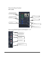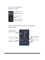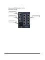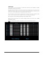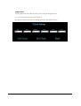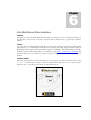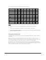
1
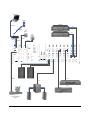
Multi - room Amp R1 AUDAC PROFESSIONAL AUDIO EQUIPMENT Multi-room Amplifier R1 User Manual & Installation Guide AUDAC PROFESSIONAL AUDIO EQUIPMENT User Manual & Installation Guide AUDAC http://www.audac.be [email protected] Index INTRODUCTION..................................................................................................................................................................................................................... 4 ENVIRONMENT ...................................................................................................................................................................................................................... 5 SAFETY REQUIREMENTS ................................................................................................................................................................................................... 6 CAUTION - SERVICING ...................................................................................................................................................................................................... 6 PIN CONNECTIONS ON CONNECTORS........................................................................................................................................................................... 7 ATTENTION .......................................................................................................................................................................................................................... 7 OVERVIEW FRONT AND REAR PANEL OF THE R1 .................................................................................................................................................... 8 FRONT:................................................................................................................................................................................................................................... 8 REAR: ..................................................................................................................................................................................................................................... 8 OVERVIEW ZONE CONTROL ............................................................................................................................................................................................ 9 ZONE 1 - 8 (FRONT).............................................................................................................................................................................................................. 9 OVERVIEW AUDIO INPUTS AND OUTPUTS 1 - 8.......................................................................................................................................................... 9 INPUT 1-8 ( REAR ) ............................................................................................................................................................................................................... 9 OVERVIEW PRIORITY INPUTS ....................................................................................................................................................................................... 10 PRIORITY INPUT 1 AND 2 (REAR) .................................................................................................................................................................................... 10 OVERVIEW CASCADED CONTROL PORTS AND AUDIOLINK .............................................................................................................................. 10 CASCADING PORTS (REAR) ............................................................................................................................................................................................ 10 OVERVIEW DATA CONTROL PORTS ............................................................................................................................................................................ 11 DATA CONTROL PART (REAR)....................................................................................................................................................................................... 11 GETTING STARTED ............................................................................................................................................................................................................ 12 SPECIAL FUNCTIONS ......................................................................................................................................................................................................... 13 SAVE SETTINGS ...................................................................................................................................................................................................................... 13 RECALL SETTINGS.................................................................................................................................................................................................................. 13 ENABLE OR DISABLE THE ROUTING BUTTONS ....................................................................................................................................................................... 13 RESET TO FACTORY SETTINGS ............................................................................................................................................................................................... 13 WIRE UP THE SYSTEM ...................................................................................................................................................................................................... 14 REMOTE CONTROL INTERFACE ................................................................................................................................................................................... 16 STANDARD WEB BASED USER INTERFACE ............................................................................................................................................................... 17 CONTROL SCREEN:........................................................................................................................................................................................................... 17 CONFIGURATION SCREEN:............................................................................................................................................................................................. 18 CHANGE PASSWORD SETTINGS.................................................................................................................................................................................... 19 CHANGE NETWORK SETTINGS ..................................................................................................................................................................................... 20 CHANGE PRIORITY SETTINGS ....................................................................................................................................................................................... 21 RESTORE FACTORY SETTINGS...................................................................................................................................................................................... 21 TIMER SETTINGS............................................................................................................................................................................................................... 22 TIME SETTINGS ................................................................................................................................................................................................................. 23 LITE WEB BASED USER INTERFACE ............................................................................................................................................................................ 24 PURPOSE: ............................................................................................................................................................................................................................ 24 ACCESS:............................................................................................................................................................................................................................... 24 START-UP SCREEN: .......................................................................................................................................................................................................... 24 ROOM CONFIGURATION SCREEN:................................................................................................................................................................................ 25 NAME CONFIGURATION SCREEN:................................................................................................................................................................................ 26 CASCADING THE R1 ........................................................................................................................................................................................................... 27 2 USING THE AUDIO LINK ................................................................................................................................................................................................... 28 WALL MOUNTED CONTROL PANELS (OPTIONAL) ................................................................................................................................................. 29 JUMPER SETTINGS FOR ZONE OUTPUT SELECTION............................................................................................................................................. 30 CONNECTING THE AUDAC PAGING SYSTEM ........................................................................................................................................................... 31 ADDITIONAL INFORMATION R1 .................................................................................................................................................................................... 33 TECHNICAL SPECIFICATIONS ................................................................................................................................................................................................. 33 PERSONAL NOTES............................................................................................................................................................................................................... 34 3 Introduction This section describes briefly the possibilities of the R1 multi-room amplifier. T he R1 multi-room amplifier is developed as an easy to use, flexible solution for multiroom use. During the development of the R1, the AUDAC-engineers wanted to achieve four goals: - Delivering a flexible audio solution to control multiple zones. - Easy to use - Excellent sound quality - An advanced digital control interface Where other multi-room amplifiers aren’t ‘all in one’ devices, the R1 is a truly polyvalent solution. It has the flexibility of an advanced multi-room amplifier, combined with several digital options. By simply surfing to the webpage, you can get full control of the R1 basic functions. The R1 can be directly plugged into a basic Ethernet LAN network. No extra control software is needed, just a computer (pda, pocket pc, …) and a web browser with the Macromedia Flash Player 8.0 (or higher) plug-in installed, will do the job. The R1 has 8 stereo line level Inputs, 8 stereo line level outputs and 8 x 40W stereo amplified outputs, 2 priority inputs, an audio link input and output. To control al these features, a RS232 port, Ethernet port, 8 RS485 ports to connect wall mounted control panels and a data uplink and downlink are present. The R1 can be used in commercial applications such as restaurants, clubs, bars, theatres, hotels, conference facilities, houses of worship, professional offices, public buildings, private houses… As a simple example, when installed in a private house, you could connect: a tuner to play your favorite radio-station in the kitchen, a CD-player to play relaxing music in the bathroom, a PC to play your MP3 songs, your TV to boost-up the surround sound while looking at your favorite movie, … and on top of it, you could also connect your doorbell to one of the priority input channels so you hear when someone is ringing at your door. Each zone can have one or more digital wall mounted control panels for selecting a music source, and setting the volume. Up to 8 wall mounted control panels are possible. It is also possible to connect the Audac Paging System to the R1 using the APM-Amplifier interface. 4 Chapter 1 Environment Do not place this unit in an enclosed environment such as a bookshelf or closet. Ensure there is adequate ventilation to cool the unit. Do not block the ventilation openings. Do not place the unit in environments which contain high levels of dust, heat, moisture or vibration. Do not use the unit near water or other liquids. Make sure no water or other liquids can be spilled, dripped or splashed on the unit. The unit is developed for indoor use only. Do not use the unit outdoors. Do not place objects (books, vases, …) on top of the unit. Place the unit on a stable base. 5 Safety Requirements Always handle the unit with care. Only use a grounded socket outlet and a power cord with grounding plug to plug in the unit. This unit is not a toy. It should not be operated by children. Do not stick objects through the ventilation openings of the R1. Do not open the unit. (risk for electrical shock) The R1 contains several ‘jumpers’ which can be set. These settings may only be done by qualified people. CAUTION - SERVICING This unit contains no user serviceable parts. Refer all servicing to qualified service personnel. Do not perform any servicing unless you are qualified to do so. Note This product conforms to the following European Standards: EN 50081-1: 1992, EN 50082-1: 1992, EN 60065: 1994 6 Pin connections on Connectors Cinch (RCA): tip = Signal (left or right), Ring = Ground RJ45 (RS485) Wall panel , Datalink: Pin 1 White-Orange / Pin 2 Orange / Pin 3 White-Green +12V DC Pin 4 Blue RS485 A Pin 5 White-Blue RS485 B Pin 6 Green Pin 7 White-Brown / Pin 8 Brown / GND RS232 (serial connection interface) The serial data protocol and wiring for the R1 can be downloaded at www.audac.be/download or can be asked at [email protected]. ATTENTION The Cat5 cabling must always be ‘straight’. In case of self made cabling, it must be done as described above, to make the system work properly. 7 Chapter 2 Overview front and rear panel of the R1 FRONT: REAR: 8 Overview Zone Control ZONE 1 - 8 (FRONT) Zone Output Level VU-Bar Status Leds Routing Leds Power Button Routing Button Zone Output 2 Band Tone Control Zone Output Volume Control Overview Audio Inputs and Outputs 1 - 8 INPUT 1-8 ( REAR ) Input Clipping LED Input Gain Control Stereo Line Input (Cinch, line level) Stereo Zone Output (Cinch, line level) Amplified Zone Outputs 8 x 40W stereo 9 Overview Priority Inputs PRIORITY INPUT 1 and 2 (REAR) Priority Input Level Gain Control Priority Input (Differential) Priority Input Contact Overview Cascaded Control Ports and Audiolink CASCADING PORTS (REAR) Dipswitch for cascading address settings Audio Link Input Data Uplink Audio Link Output Data Downlink 10 Overview DATA Control Ports DATA CONTROL PART (REAR) Ethernet connection (RJ45) Serial Control Port (RS232) Wall Panel Outlets (RS485) Power Socket and Fuse 11 Chapter 3 Getting Started When turning on the power, the R1 start-up procedure will take place. This will take about 30sec.. The red “Wait” led will light up when the power is switched on. When the start-up procedure has completed, the green “Run” led will light up and the R1 is ready to be used. On the front panel you can route an Input channel to a specific Zone output simply by pressing the routing button of the Zone output. The led of the selected Input for the Zone output will light up. By pressing the button a second time, you will choose the next Input channel to be routed to the Zone output. Treble (High), Bass (Low) and Volume (Vol.) of the Zone outputs can be changed on the front panel. Stereo VU-bars indicate the signal level on the output Zones. On the rear panel, the gain of the Input channels and the priority channels can be adjusted. When an input signal is clipping, the clipping led of the input on the back panel will light up red. The output section on the rear panel of the R1 has 8 stereo line level Zone Outputs and 8 stereo amplified Zone Outputs (8 x 40W stereo at 4ohm). The R1 can be controlled with Wall Mounted Control Panels (RS-485). Each Wall Mounted Control Panel has to be set to control the right output Zone. This can be done by setting “jumpers” on the inside of the Wall Mounted Control Panel. It is also possible to connect the Audac Paging System to the R1. The R1 has also 2 differential Priority Input channels with gain control. When one of the priority contacts is closed, the according Priority input is switched on and will be routed to all ( !! ) output Zones. Priority input 1 has the highest priority. This means that when both Priority contacts are closed, Priority input 1 will be the routed to all zone outputs, discriminating Priority input 2. More advanced changes to the priority settings can be made via the website. (see chapter 5) 12 Special functions When using one of these special functions, all the routing leds on the front of the R1 will blink a couple of times to indicate the functions is being processed. When the blinking stops, the function has been processed and you can release the pressed buttons. Save settings Routing settings can be saved by pressing simultaneously the buttons on ‘Zone 7’ and ‘Zone 8’ on the front panel of the R1. Hold down the 2 buttons for about 10 seconds. Recall settings Recalling the saved routing settings can be done by pressing simultaneously the buttons ‘Zone 5’ and ‘Zone 6’ on the front panel of the R1. Hold down the 2 buttons for about 10 seconds. Enable or disable the routing buttons The routing buttons (Zone 1 to Zone 8) on the front panel of the R1 can be disabled by pressing together the buttons of ‘Zone 3’ and ‘Zone 4’. Hold down the 2 buttons for at least 10 seconds. To enable the routing buttons on the front panel of the R1, press down the ‘Zone 3’ and the ‘Zone 4’ buttons simultaneously for at least 10 seconds. Reset to factory settings To reset the R1 to the original factory settings, hold down the “Zone 1” and “Zone 2” buttons for at least 20 seconds. The R1 will restart, the “wait” led will go on and after about 30 seconds the green “run” led will light up. The R1 settings are now restored to the factory settings, this means the IP-address will be reset to 192.168.0.181 (subnetmask 255.255.255.0) and all previously saved settings will be lost. REMEMBER If you do not save the routing settings, the next time the R1 starts up, it will recall the standard or previously saved settings !!!! 13 Chapter 4 Wire up the System The AUDAC R1 amplifier is very easy in use. Following cable specs must be followed to guarantee a correct operation: 1. Speaker cable for amplified zone outputs: minimum 2x1.5 mm2 (distance >15m: 2x2.5mm2) 2. Wall Mounted Panel: UTP/FTP Cat5 cable 3. Music sources and line level zone outputs: must be connected with audio cable of good quality 4. Ethernet connection: UTP/FTP cat5 cable 14 Notebook Pocket PC Amplifier 1 Ethernet R+L Wireless Amplifier 2 Wall panel 1 R+L Wall panel 2 Wireless Router RS485 Ethernet RS485 R L RS232 R+L L+R Tuner R +L L R CD player Sub Home automation systems 15 Chapter 5 Remote Control Interface To use the remote control interface, the R1 has to be plugged into an Ethernet LAN network with a standard (straight) network cable. Make sure the R1 default network address (IP-address: 192.168.0.181, subnetmask: 255.255.255.0) is within range of the connected Ethernet LAN network ! If the R1 default network address is not within range of your LAN network, contact your network specialist. The default network address can be changed with the Standard Web Based User Interface but therefore a network connection has to be made first !! A pc (or pda, pocket pc, …1) with a web browser and the Macromedia Flash 8.0 plug-in (or higher) installed, is necessary to use the web based user interfaces. The pc needs to be connected within the same Ethernet LAN network. The default URL for the Standard Web Based User Interface is: http://192.168.0.181 The default URL for the Lite Web Based User Interface is: http://192.168.0.181/small.html Be aware: the letters are case sensitive !! 1 pda or pocket PC with at least a 312MHz processor or better 16 Standard Web Based User Interface CONTROL SCREEN: When you surf to the webpage of the R1, you will see the control screen of the R1. Default the IP address is http://192.168.0.181 The “Connection Status” will indicate “online” if a connection with the R1 has been made. Following changes can be made: routing of the input channels to the zone outputs, volume settings of the Zone outputs and Zone output muting. The settings of the front panel controls can be saved by pressing the “Save Settings” button, and the saved setting can be recalled by pressing the “Recall Settings” button. 17 CONFIGURATION SCREEN: This window will be opened after pressing the “Configuration” button in the control window and after logging in. (Default Username: audac, default password: R1 ) In this window you can choose to change the password settings to get into the configuration screen, change the network settings of the R1, change the priority settings of the R1, restore the R1’s original ( !! ) factory settings, set timers and set the date and clock in the time settings window. 18 CHANGE PASSWORD SETTINGS The user name and password can be changed in this window. There is a secret “rescue” password in case of emergency (passwords lost). This can be asked at [email protected] . After the change of settings, press the “Change Settings” button. The “Change Settings” button must be pressed to save the changed parameters. 19 CHANGE NETWORK SETTINGS In this window the IP-address can be changed manually or can be set to DHCP. Do not forget to press the “Change Settings” button after the changes are made !! Standard the IP-address will be 192.168.0.181. (The subnetmask is set fixed to 255.255.255.0) Be aware: When set to DHCP, the DHCP-server of the network will automatically give a free IPaddress to the R1. You will have to find out this IP-address yourself to be able to surf to the R1’s website !!!! The next time you start-up the R1, the IP-address given by the DHCP-server can be different !!!! If you don’t know the given IP-address, the R1 will be lost in the network !!! It is possible to restore the factory settings and thus also the factory network address by pressing together the routing buttons of Zone 1 and Zone 2 and holding them down for 20 seconds. To use the automatic time adjustment, you need to fill in an ip-address for the R1, the default gateway of your network, an ip-address of a timeserver and the time zone. Check the NTP option and do not forget to press the “Change settings” button. Time zones marked with a ” * ” uses daylight saving time. Timeservers can be found on: http://www.eecis.udel.edu/~mills/ntp/clock1a.html http://ntp.isc.org/bin/view/Servers/StratumOneTimeServers 20 CHANGE PRIORITY SETTINGS Here you can enable or disable both priority channels. You can also choose on which Zone output you want to route the priority channels. Remember: if you enable both priority channels and you route them to the same zone output, priority channel 1 will have the highest priority in case both priority channels are switched on. Do not forget to press the “Change Settings” button when you are done. RESTORE FACTORY SETTINGS BE CAREFULL to press this button. It really will recall the ORIGINAL factory settings !!! It does not recall previously saved settings. In stead, it recalls the original factory settings !! If you want to recall previously saved settings, you need to press the “Recall Settings” button in the “Control Screen” or press simultaneously the buttons ‘Zone 5’ and ‘Zone 6’ on the front panel of the R1. Hold down the 2 buttons for about 10 seconds. 21 TIMER SETTINGS In this window you can set 8 timers on a weekly base. The timers can be disabled or enabled individually by checking the enable box. An input zone can be routed to one or more output zones. The input zone can be chosen in the dropdown list and the output zones can be chosen by checking the checkboxes. The action can be set to “On” or “Off” which means the routing will be made or released. Hour and minutes can be chosen from a dropdown list. The days of the week on which the timer needs to be active (when the timer is enabled) can be set by checking the checkboxes. Do not forget to save the settings by pressing the “Save Settings” button. Make sure the date and time is set correctly. Setting the time can be done in the “TIME SETTINGS” window. Note: An “Output Zone” can have a maximum of 4 “On” and 4 “Off states each day. 22 TIME SETTINGS In this window the date and time can be set by using the dropdown lists. To set the clock press the “Set Clock” button. To readout the date and time from the R1, press the “Get Clock” button. 23 Chapter 6 Lite Web Based User interface PURPOSE: The purpose of the Lite Web Based User Interface is to offer easy access to the basic functions of the R1 and to offer access to the R1 on devices with a small screen, e.g. pocket PC’s, PDA’s, GSM’s … ACCESS: To access the Lite Web Based User Interface you will need a web browser with the “Macromedia Flash Player 8 ” or “Macromedia Flash Player 8 for pocket PC 2003” plug-in installed. The Lite Web Based User Interface can be accessed by typing “/small.html” after the IP-address of the R1. If the R1 has the standard IP-address, you will have to type: http://192.168.0.181/small.html (Be aware: the letters are case sensitive !!). It takes a couple of seconds to load the Flash controls in the website. START-UP SCREEN: The start-up screen let’s you select the Room ( = zone output) you wish to control. Press on the ”– “ or “ + “ button on the screen to select the wanted Room and press “ GO “. After you have pressed “ GO “, you will see the ” Room Configuration Screen “. 24 ROOM CONFIGURATION SCREEN: In this screen you can assign an input source to the selected room, change the output volume or mute the output volume. To configure another room or to go back to the “ Start-up Screen “, press on the name of the selected room. To change the names of the input sources and/or the rooms, press 3 times the “ Audac “ logo on the bottom of the screen. 25 NAME CONFIGURATION SCREEN: This screen can be activated by pressing 3 times on the “Audac” logo in the “Room Configuration Screen”. Here you can change the names of the “ Rooms“ and the names of the “ Input Sources“. By pressing the “ – “ and the “ + “ buttons on the screen you can navigate throughout the list of room names and input source names. By placing the cursor in the field and using the keyboard you can change the names to your flavour. When the changes are made, press the “ Save” button. 26 Chapter 7 Cascading the R1 It is possible to place up to 16 R1 multi-room amplifiers in cascade. To cascade R1’s, you need to give each R1 a cascade address, this is done by setting the dipswitch at the rear panel. Make sure there is always one R1 configured as master and each address can be used only one time. The Data Uplink of the master needs to be connected to the Data Downlink of the first slave. The Data Uplink of the first slave needs to be connected to the Data Downlink of the second slave… and so on. Further more, each R1 needs to be connected to the same local network using the Ethernet remote control port. This also means that each R1 needs to have its unique IP-address in the local Ethernet network. To give each R1 an unique IP-address, DHCPmode will be enabled automatically when the cascade address of the R1 is within the slave range !! One of the advantages of cascading R1’s is that you will have an easy to use web interface to control all of the cascaded R1’s. When you want to change the settings of one of the cascaded R1’s, you only have to surf to the website of the ‘master’ R1. The web page you see now is extended with tabs on the bottom. You only have to click on the correct tab, wait until the R1’s settings are uploaded to the website and you will be able to change the settings of the desired R1. **** TO DO: Picture tabbed webpage **** Another advantage is that you can use more then 8 wall mounted control panels to control only one zone. The number of wall mounted control panels to control one zone is limited to 32. 27 In a cascaded setup, the Zone outputs are numbered as follows: Cascade setting Zone 1 Master Slave 1 Slave 2 Slave 3 Slave 4 Slave 5 Slave 6 Slave 7 Slave 8 Slave 9 Slave 10 Slave 11 Slave 12 Slave 13 Slave 14 Slave 15 1 9 17 25 33 41 49 57 65 73 81 89 97 105 113 121 Zone 2 2 10 18 26 34 42 50 58 66 74 82 90 98 106 114 122 Zone 3 3 11 19 27 35 43 51 59 67 75 83 91 99 107 115 123 Zone 4 4 12 20 28 36 44 52 60 68 76 84 92 100 108 116 124 Zone 5 5 13 21 29 37 45 53 61 69 77 85 93 101 109 117 125 Zone 6 6 14 22 30 38 46 54 62 70 78 86 94 102 110 118 126 Zone 7 Zone 8 7 15 23 31 39 47 55 63 71 79 87 95 103 111 119 127 8 16 24 32 40 48 56 64 72 80 88 96 104 112 120 128 Note: - Only the first 32 zones can be controlled using the wall mounted control panels. - A zone can be controlled by a maximum of 32 wall mounted control panels. - The maximum combined cable length of the wall mounted control panels should be less then 500 meters (RS485 specification). Using the Audio Link At the rear panel two D-sub 25 pole connectors are available to link through audio of one R1 to another R1. Make sure that when you link through audio from one R1 to another, no audio sources are connected to the inputs of the R1 where you use the Audio Link Input. So the rule is: when you use the Audio Link Input, no other audio sources are connected to the Line Inputs. The advantage of the Audio Link is that when you have 8 or less input sources and need more then 8 Zone outputs, you can connect the input sources to another R1 with one single cable. This means a smaller pile of cables at the rear and a cleaner rack setup. 28 Chapter 8 Wall Mounted Control Panels (Optional) The R1 Multi-room amplifier can be equipped with wall mounted control panels to control each Zone output. A Zone output can be controlled by more then one wall mounted control panel. The maximum number of wall mounted control panels connected to a R1 multi-room amplifier is eight. These wall mounted control panels are controlled by a RS485 data bus and must be connected to the R1 with “twisted pair” or “CAT5” cable. Following settings can be changed: - Volume of the Zone output which the panel is configured for (e.g. Zone 1) - Input source selection for the Zone output. (e.g. CD player, Tuner, Computer, …) The wall mounted control panel can be configured to control the settings of a Zone output (e.g. Living room, Board room …). This is done by jumper settings on the inside of the wall mounted control panel. If the wall mounted control panel is connected to the R1, and the R1 is turned on, the digit on the wall mounted control panel will show a zero for a couple of seconds, for the next couple of seconds it will show the zone output for which the wall mounted control panel is configured and last it will keep displaying the selected input source. When changing the volume of the zone output, the digit on the wall mounted control panel will show the zone outputs volume. The volume will be changed in smaller steps then the digit can show. If one of the volume control buttons is held down, the volume will keep increasing or decreasing. After the change has been made, the digit will show again the selected input source. 29 Jumper settings for zone output selection A B C D E A J J J J J J J J J J J J J J J J B J J J J J J J J C D E J J J J J J J J J J J J J J J J J J J J J J J J J J J J J J J J J J J J J J J J J J J J J J J J J J J J J J J J Zone output 1 2 3 4 5 6 7 8 9 10 11 12 13 14 15 16 17 18 19 20 21 22 23 24 25 26 27 28 29 30 31 32 Cascade settings Master Slave 1 Slave 2 Slave 3 30 J = set jumper Chapter 9 Connecting the Audac Paging System The Audac Paging System can be connected to the R1 Multi-room amplifier. To connect the Audac Paging System to the R1 an additional module, the “APM-Amplifier interface”, is necessary. On one side of this APM-Amplifier interface you can connect the Audac Paging System (RJ45 connector) and an optional 24V power supply to power the interface and the paging system. On the other side of the interface, you can connect to the R1. The data connection (RJ45 connector) to the R1 needs to be plugged into one of the RS485 ports on the back of the R1. The audio connection (RCA jack) must always be connected to the first line input channel (Line 1) of the R1. Cable specifications for the R1-side of this interface are described in chapter 1 of this manual. A simple diagram is drawn on the next page. It is possible to cascade 4 R1 multi-room amplifiers and control each of the output zones with the paging system. This means 32 output zones can be controlled individually with the Audac Paging System. Cascading R1’s is described in chapter 7 of this manual. How to configure the Audac Paging System for a setup with the Audac R1 will be described in the help file of the Audac Paging System Configuration Tool. 31 ARJ3 ARJ3 APM01 ARJ3 APM04 ARJ3 APM08 ARU04 ARJ3 ARU08 ARJ3 ARU16 ARJ3 +24V APM16 APM-Amplifier interface 32 Chapter 10 Additional Information R1 Technical specifications Sensitivity Line input -20/+4 dB 25k Ohm Frequency response THD+N by 1 kHz Signal to Noise ratio Slew rate 20 Hz – 20 kHz less than 0.1% 100 dB@1kHz +/- 13V/µsec Digital control Remote zone control Web based control RS-232 RS-485 Ethernet Zone outputs 1-8 +3dB 100 Ohm unbalanced Output power per channel (R1) 20 Watt 8 Ohm 40 Watt 4 Ohm Power Supply Max. power consumption R1 Lite Max. power consumption R1 240V AC, 50-60Hz 60 W TBD W Weight R1 Lite Weight R1 Dimensions (B x H x D) Unit height 10 kg 16 kg 482 mm x 132mm x 350mm 3HE 33 Personal Notes 34