1
FRORU#WHOHYLVLRQ#
Fkdvvlv = N49D+Q,bPL
Prgho = FO5<P73PT5[[D[#
VHUYLFH
Pdqxdo
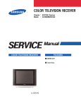
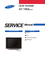
FRORU#WHOHYLVLRQ
IHDWXUHV
■ Turbo Plus
■ DNIe jr.
■ Low Stand-By Power Wattage
■ SOUND Equalizer
CL-29M40MQ
This Service Manual is a property of Samsung Electronics Co.,Ltd.
Any unauthorized use of Manual can be punished under applicable
International and/or domestic law.
© Samsung Electronics Co., Ltd. Dec. 2006
Printed in Korea
AA82-04286A
Table of Contents
Chapter 1 Precaution
■ 1-1 Safety Precautions . . . . . . . . . . . . . . . . . . . . . . . . . . . . . . . . . . . . . . . . . . . . . . . . . . . . . . . . . . . 1-1
■ 1-2 Servicing Precautions . . . . . . . . . . . . . . . . . . . . . . . . . . . . . . . . . . . . . . . . . . . . . . . . . . . . . . . . 1-3
■ 1-3 Static Electricity Precautions . . . . . . . . . . . . . . . . . . . . . . . . . . . . . . . . . . . . . . . . . . . . . . . . . . . 1-4
■ 1-4 Installation Precautions . . . . . . . . . . . . . . . . . . . . . . . . . . . . . . . . . . . . . . . . . . . . . . . . . . . . . . . 1-5
Chapter 2 Product Specification
■ 2-1 Product Features . . . . . . . . . . . . . . . . . . . . . . . . . . . . . . . . . . . . . . . . . . . . . . . . . . . . . . . . . . . . 2-1
■ 2-2 Key Features . . . . . . . . . . . . . . . . . . . . . . . . . . . . . . . . . . . . . . . . . . . . . . . . . . . . . . . . . . . . . . . 2-2
■ 2-3 Specifications Analysis . . . . . . . . . . . . . . . . . . . . . . . . . . . . . . . . . . . . . . . . . . . . . . . . . . . . . . . . 2-3
■ 2-4 Accessories . . . . . . . . . . . . . . . . . . . . . . . . . . . . . . . . . . . . . . . . . . . . . . . . . . . . . . . . . . . . . . . . 2-4
Chapter 3 Alignment & Adjustment
■ 3-1 Service Instruction . . . . . . . . . . . . . . . . . . . . . . . . . . . . . . . . . . . . . . . . . . . . . . . . . . . . . . . . . . . 3-1
■ 3-2 How to Access Service Mode . . . . . . . . . . . . . . . . . . . . . . . . . . . . . . . . . . . . . . . . . . . . . . . . . . . 3-2
■ 3-3 Factory Data . . . . . . . . . . . . . . . . . . . . . . . . . . . . . . . . . . . . . . . . . . . . . . . . . . . . . . . . . . . . . . . . 3-3
■ 3-4 Service Adjustment . . . . . . . . . . . . . . . . . . . . . . . . . . . . . . . . . . . . . . . . . . . . . . . . . . . . . . . . . . 3-10
■ 3-5 Software Upgrade . . . . . . . . . . . . . . . . . . . . . . . . . . . . . . . . . . . . . . . . . . . . . . . . . . . . . . . . . . . 3-12
■ 3-6 Replacements & Calibration . . . . . . . . . . . . . . . . . . . . . . . . . . . . . . . . . . . . . . . . . . . . . . . . . . . . 3-16
Chapter 4 Exploded View & Part List
■ 4-1 CL29M40MQ2XXAX . . . . . . . . . . . . . . . . . . . . . . . . . . . . . . . . . . . . . . . . . . . . . . . . . . . . . . . . . 4-1
Chapter 5 Electrical Part List
■ 5-1 CL29M40MQ2XXAX . . . . . . . . . . . . . . . . . . . . . . . . . . . . . . . . . . . . . . . . . . . . . . . . . . . . . . . . . 5-1
Chapter 6 Troubleshooting
■ 6-1 Checkpoints by Error Mode . . . . . . . . . . . . . . . . . . . . . . . . . . . . . . . . . . . . . . . . . . . . . . . . . . . . 6-1
■ 6-2 Troubleshooting Procedures by Error Modes . . . . . . . . . . . . . . . . . . . . . . . . . . . . . . . . . . . . . . . 6-3
■ 6-3 Troubleshooting Procedures by ASS'Y . . . . . . . . . . . . . . . . . . . . . . . . . . . . . . . . . . . . . . . . . . . 6-4
Chapter 7 Block Diagram
■ 7-1 Overall Block Diagram . . . . . . . . . . . . . . . . . . . . . . . . . . . . . . . . . . . . . . . . . . . . . . . . . . . . . . . . 7-1
■ 7-2 Partial Block Diagram . . . . . . . . . . . . . . . . . . . . . . . . . . . . . . . . . . . . . . . . . . . . . . . . . . . . . . . . . 7-2
Chapter 8 Wiring Diagram
■ 8-1 Overall Wiring . . . . . . . . . . . . . . . . . . . . . . . . . . . . . . . . . . . . . . . . . . . . . . . . . . . . . . . . . . . . . . . 8-1
■ 8-2 Pin Connection . . . . . . . . . . . . . . . . . . . . . . . . . . . . . . . . . . . . . . . . . . . . . . . . . . . . . . . . . . . . . . 8-2
Chapter 9 PCB Diagram
■ 9-1 Main Board . . . . . . . . . . . . . . . . . . . . . . . . . . . . . . . . . . . . . . . . . . . . . . . . . . . . . . . . . . . . . . . . . 9-1
■ 9-2 PIP Module . . . . . . . . . . . . . . . . . . . . . . . . . . . . . . . . . . . . . . . . . . . . . . . . . . . . . . . . . . . . . . . . . 9-4
■ 9-3 CRT Board . . . . . . . . . . . . . . . . . . . . . . . . . . . . . . . . . . . . . . . . . . . . . . . . . . . . . . . . . . . . . . . . . 9-5
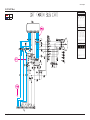
Chapter 10 Schematic Diagram
■ 10-1 Power & Deflection Block . . . . . . . . . . . . . . . . . . . . . . . . . . . . . . . . . . . . . . . . . . . . . . . . . . . . . 10-1
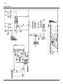
■ 10-2 IF & UOC(Chroma_Micom) Block . . . . . . . . . . . . . . . . . . . . . . . . . . . . . . . . . . . . . . . . . . . . . . 10-2
■ 10-3 PIP & CRT Block . . . . . . . . . . . . . . . . . . . . . . . . . . . . . . . . . . . . . . . . . . . . . . . . . . . . . . . . . . . 10-3
■ 10-4 AV & Sound Block . . . . . . . . . . . . . . . . . . . . . . . . . . . . . . . . . . . . . . . . . . . . . . . . . . . . . . . . . . 10-4
Precaution
1. Precaution
To avoid possible damages or electric shocks or exposure to radiation, follow the instructions below with regard to safety,
installation, service and ESD.
1-1 Safety Precautions
1.
Make sure all protective devices are properly installed
including non-metallic handles and compartment covers
when installing or re-installing the chassis or chassis
assemblies.
2.
Make sure that no gaps exist between the cabinets for
children to insert their fingers in to prevent children from
receiving electric shocks. Gaps mentioned above include
ventilation holes of a too great magnitude between the
vaccum tube and the cabinet mask, and the improper
installation of the rear cabinet.
5.
Warning for Engineering Changes:
Never make any changes or additions to the circuit
design or the internal part for this product.
Ex: Do not add any audio or video accessory
connectors. This might cause physical damage.
Furthermore, any changes or additions to the original
design/engineering will invalidate the warranty.
6.
Warning - Hot Chassis:
Some TV chassis are directly connected to one end of
the AC power cord for electrical reasons.
Without insulated transformers, the product can only be
repaired safely when the chassis is connected to the
earthed end of the AC power source.
Errors may occur when the resistance is below 1.0 ㏁ or
over 5.2 ㏁.
In these cases, make sure that the device is repaired
before sending it back to the customer.
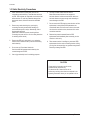
3.
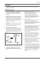
Check for Electricity Leakage (Figure 1-1)
Warning: Do not use an insulated transformer for checking the leakage. Use only those current leakage testers
or mirroring systems that comply with ANSIC 101.1 and
the Underwriter Laboratory's specifications (UL1410,
59.7).
LEAKAGE
CURRENT
TESTER
DEVICE
UNDER
TEST
2-WIRE CORD
EARTH
GROUND
Fig. 1-1 AC Leakage Test
4.
A high voltage is maintained within the specified limits
using safety parts, calibration and tolerances. When
voltage exceeds the specified limits, check each special
part.
Samsung Electronics
7.
Some TV chassis are shipped with an additional
secondary grounding system. The secondary system is
adjacent to the AC power line. These two grounding
systems are separated in the circuit using an
unbreakable/unchangeable insulation material.
8.
When any parts, material or wiring appear overheated or
damaged, replace them with new regular ones
immediately. When any damage or overheating is
detected, correct this immediately and make a regular
check of possible errors.
(READING SHOULD
NOT BE ABOVE
0.5mA)
TEST ALL
EXPOSED METAL
SURFACES
ALSO TEST WITH
PLUG REVERSED
(USING AC ADAPTER
PLUG AS REQUIRED)
To make sure the AC power cord is properly connected,
follow the instructions below. Use the voltmeter to
measure the voltage between the chassis and the
earthed ground. If the measurement is over 1.0V, unplug
the AC power cord and change the polarity before reinserting it. Measure the voltage between the chassis
and the ground again.
9. Check for the original shape of the lead, especially that
of the antenna wiring, any sharp edges, the AC power
and the high voltage power. Carefully check if the wiring
is too tight, incorrectly placed or loose. Never change the
space between the part and the printed circuit board.
Check the AC power cord for possible damages. Keep
the part or the lead away from any heat-emitting
materials.
1-1
Precaution
10. Safety Indication:
Some electrical circuits or device related materials
require special attention to their safety features, which
cannot be viewed by the naked eye. If an original part is
replaced with another irregular one, the safety or
protective features will be lost even if the new one has a
higher voltage or more watts.
Critical safety parts should be bracketed with (
! ).
Use only regular parts for replacements (in particular,
flame resistance and dielectric strength specifications).
Irregular parts or materials may cause electric shock or
fire.
1-2
Samsung Electronics
Precaution
1-2 Servicing Precautions
Warning 1: First carefully read the "Safety Instruction" in this service manual.
When there is a conflict between the service and the safety instructions, follow the safety instruction at all times.
Warning 2: Any electrolytic capacitor with the wrong polarity will explode.
1.
The service instructions are printed on the cabinet, and
should be followed by any service personnel.
2.
Make sure to unplug the AC power cord from the power
source before starting any repairs.
(a) Remove or re-install parts or assemblies.
(b) Disconnect the electric plug or connector, if any.
(c) Connect the test part in parallel with the electrolytic
capacitor.
3.
4.
5.
6.
Insulation Check Process: Unplug the power cord from
the AC source and turn the switch on. Connect the insulating resistance meter (500v) to the AC plug blade.
The insulating resistance between the blade of the AC
plug and that of the conductive material should be more
than 1 ㏁.
7.
Some parts are placed at a higher position than the
printed board. Insulated tubes or tapes are used for this
purpose. The internal wiring is clamped using buckles to
avoid contact with heat emitting parts. These parts are
installed back to their original position.
Any B+ interlock should not be damaged.
If the metal heat sink is not properly installed, no
connection to the AC power should be made.
8.
After the repair, make sure to check if the screws, parts
or cables are properly installed. Make sure no damage is
caused to the repaired part and its surroundings.
Make sure the grounding lead of the tester is connected
to the chassis ground before connecting to the positive
lead. The ground lead of the tester should be removed
last.
9.
Beware of risks of any current leakage coming into
contact with the high-capacity capacitor.
Check for insulation between the blade of the AC plug
and that of any conductive materials (i.e. the metal
panel, input terminal, earphone jack, etc).
10. The sharp edges of the metal material may cause
physical damage, so ensure wearing protective gloves
during the repair.
Samsung Electronics
1-3
Precaution
1-3 Static Electricity Precautions
1.
Some semi-conductive ("solid state") devices are
vulnerable to static electricity. These devices are known
as ESD. ESD includes the integrated circuit and the field
effect transistor. To avoid any materials damage from
electrostatic shock, follow the instructions described
below.
2.
Remove any static electricity from your body by
connecting the earth ground before handling any
semi-conductive parts or ass'ys. Alternatively, wear a
dischargeable wrist-belt.
(Make sure to remove any static electricity before
connecting the power source - this is a safety instruction
for avoiding electric shock)
3.
Remove the ESD ass'y and place it on a conductive
surface such as aluminum foil to prevent accumulating
static electricity.
4.
Do not use any Freon-based chemicals.
Such chemicals will generate static electricity that
causes damage to the ESD.
5.
Use only grounded-tip irons for soldering purposes.
6.
Use only anti-static solder removal devices.
Most solder removal devices do not support an
anti-static feature. A solder removal device without an
anti-static feature can store enough static electricity to
cause damage to the ESD.
7.
Do not remove the ESD from the protective box until the
replacement is ready. Most ESD replacements are
covered with lead, which will cause a short to the entire
unit due to the conductive foam, aluminum foil or other
conductive materials.
8.
Remove the protective material from the ESD
replacement lead immediately after connecting it to the
chassis or circuit ass'y.
9.
Take extreme caution in handling any uncovered ESD
replacements. Actions such as brushing clothes or lifting
your leg from the carpet floor can generate enough static
electricity to damage the ESD.
CAUTION
These servicing instructions are for use by
qualified service personnel only.
To reduce the risk of electric shock do not
perform any servicing other than that contained in the
operating instructions unless you are qualified to do so.
1-4
Samsung Electronics
Precaution
1-4 Installation Precautions
1.
For safety reasons, more than two people are required
for carrying the product.
2.
Keep the power cord away from any heat emitting
devices, as a melted covering may cause fire or electric
shock.
3.
Do not place the product in areas with poor ventilation
such as a bookshelf or closet. The increased internal
temperature may cause fire.
4.
Bend the external antenna cable when connecting it to
the product. This is a measure to protect it from being
exposed to moisture. Otherwise, it may cause a fire or
electric shock.
5.
Make sure to turn the power off and unplug the power
cord from the outlet before repositioning the product.
Also check the antenna cable or the external connectors
if they are fully unplugged. Damage to the cord may
cause fire or electric shock.
Samsung Electronics
6.
Keep the antenna far away from any high-voltage cables
and install it firmly. Contact with the high-voltage cable or
the antenna falling over may cause fire or electric shock.
7.
Check the basics of the screen test.
- Image position/size, Tilt adjustment
1-5
MEMO
1-6
Samsung Electronics
Alignment & Adjustment
3. Alignment & Adjustment
3-1 Service Instruction
1. General Adjustment :
In general, a color TV can provide ideal visual quality by adjusting the basic settings such as the vertical size, horizontal size,
focus, etc.
Display a black and white picture on the screen to check if the picture is clearly displayed.
If there are some 'spotted' points on the screen when displaying a black and white picture, degauss the screen using the
degauss coil. If the spotted points remain, re-adjust the purity and the convergence.
This completes the basic performance examination.
Notice.
■ These adjustments and the check list are only applied to K16A chassis-applied models.
■ Only use 230V for the measurement set. It is recommended using an insulation transformer when supplying power to
the set so as to prevent shock to the set or to yourself.
■ These adjustment specifications have been created on the basis of the domestic K16A chassis-applied remote control
model. Some of the contents may be changed subject to the sales location and the product specifications.
※When replacing the Module Service Instruction
1. When replacing the MAIN Board : Tilt adjustment, Focus adjustment, Screen voltage, W/B adjustment are all required. Since
the settings including the Channel information, Deflection, etc. are saved to the EEPROM,
recogfigure these settings when replacing the MAIN Board.
The notation of the software information : T-RHMNSA-1000 refer to "GREEN2 BASIC MODEL EUROPE. ver.1000"
Since the settings including the Channel information, Deflection, etc. are
saved to the EEPROM, recogfigure these settings when replacing the MAIN Board.
2. When replacing the CRT Ass'y : No adjustments required
3. When replacing the front panel Master Power switch : No adjustments required
4. When replacing the Side AV Ass'y : No adjustments required
5. When replacing the PIP Module : No adjustments required
6. When replacing the Control Ass'y : No adjustments required
7. When replacing the PFC Ass'y : No adjustments required
Samsung Electronics
3-1
Alignment & Adjustment
3-2 How to Access Service Mode
1. To enter Service Mode, press the keys on the remote control according to the following sequence. (in Stand-by status)
Mute → 1 → 8 → 2 → Power On
※ When failing to enter Service Mode, repeat the procedure above.
2. The initial screen of Service Mode.
Option1 XX XX XX XX XX
Option2
Deflection
Video Adjust1
Video Adjust2
Video Adjust3
Video Adjust4
Video Adjust5
YC Delay
Others
Bus Stop Off
CHECKSUM 0000
G2 Adjust
RESET
T-RHMNSA-XXXX 20XX/XX/XX
3. Functions of the Keys within Service Mode.
3-2
MENU
Show all menus
▲ /▼
Move the cursor to select an item.
◀/▶
Adjust the selected configuration value
Samsung Electronics
Alignment & Adjustment
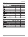
3-3 Factory Data
★ The underlined are items applied during the service adjustment. None of the others should be adjusted.
1. Option1
Model
No
Item
Var./Fixed
CL29M16MQ
CL29M2MQ
CL29M21FQ
CL29T21FQ
1
System
Var.
CL
CL
CL
2
Video Mute
Var.
400msec
400msec
400msec
3
AV Jack
Var.
2RCA+S+DVD
2RCA+S+DVD
2RCA+S+DVD
4
Sound
Var.
Stereo
Stereo
Stereo
5
Volume Curve
Var.
Large
Large
Large
6
Initial Lang.
Var.
Engilsh
Engilsh
Engilsh
7
Tilt
Var.
Off
Off
On
8
DNIe Jr
Var.
Off
On
On
9
PIP
Var.
Off
Off
2-Tuner
10
Auto Power On
Var.
Off
Off
Off
11
Caption
Var.
On
On
On
12
Vchip
Var.
Off
Off
Off
13
Child Look
Var.
Off
Off
Off
14
Plug Play
Var.
On
On
On
15
StandBy LED
Var.
Off
Off
Off
2. Option2
Model
No
Item
Var./Fixed
CL29M16MQ
CL29M2MQ
CL29M21FQ
CL29T21FQ
1
X-Ray Protect
Var.
Off
Off
Off
2
High Deviation
Var.
Off
Off
Off
3
V-Guard
Var.
On
On
On
4
ACS
Var.
Off
Off
Off
5
CRT
Var.
4:3 Zoom
4:3 Zoom
4:3 Zoom
6
LNA
Var.
Off
Off
On
7
Hotel Mode
Var.
Off
Off
Off
8
Philippines
Var.
Off
Off
Off
Samsung Electronics
3-3
Alignment & Adjustment
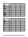
3. Deflection(NTSC 60Hz)
Model
No
Item
Var./Fixed
CL29M16MQ
CL29M2MQ
CL29M21FQ
CL29T21FQ
1
V Amp
Var.
47
47
47
2
V Shift
Var.
24
24
24
3
H EW
Var.
48
48
48
4
H Shift
Var.
49
49
49
5
V Linearity
Var.
30
30
30
6
V S-Correction
Fixed
32
32
32
7
V Slope
Fixed
30
30
30
8
V Scroll
Fixed
25
25
25
9
V Zoom
Fixed
48
48
48
10
H Parabola
Var.
45
45
45
11
Upper Corner
Var.
51
51
51
12
Lower Corner
Var.
54
54
54
13
H Trapezium
Var.
22
22
22
14
Bow
Var.
26
26
26
15
Angle
Var.
29
29
29
4. Deflection(PAL N 50Hz)
Model
No
Item
Var./Fixed
CL29M16MQ
CL29M2MQ
CL29M21FQ
CL29T21FQ
1
V Amp
Var.
0
0
0
2
V Shift
Var.
0
0
0
3
H EW
Var.
0
0
0
4
H Shift
Var.
-6
-6
-6
5
V Linearity
Fixed
0
0
0
6
V S-Correction
Fixed
0
0
0
7
V Slope
Fixed
0
0
0
8
V Scroll
Fixed
0
0
0
9
V Zoom
Fixed
0
0
0
10
H Parabola
Fixed
0
0
0
11
Upper Corner
Fixed
0
0
0
12
Lower Corner
Fixed
0
0
0
13
H Trapezium
Fixed
0
0
0
14
Bow
Fixed
0
0
0
15
Angle
Fixed
0
0
0
3-4
Samsung Electronics
Alignment & Adjustment
Samsung Electronics
3-5
Alignment & Adjustment
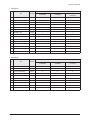
5. Video Adjust1
Model
No
Item
Var./Fixed
CL29M16MQ
CL29M2MQ
CL29M21FQ
CL29T21FQ
1
R Cutoff
Var.
20
20
20
2
B Cutoff
Var.
49
49
49
3
R Drive
Var.
29
29
29
4
G Drive
Fixed
15
15
15
5
B Drive
Var.
21
21
21
6
Sub Bright
Var.
17
17
17
7
Sub Contrast
Var.
7
7
7
8
PAL/SECAM Sub Color
Fixed
23
23
23
9
NTSC Sub Color
Fixed
21
21
21
10
NTSC Sub Tint
Fixed
15
15
15
11
YUV Sub Tint
Fixed
32
32
32
12
AKB Option
Fixed
0
0
0
13
Peaking CFO & Delay Mode
Fixed
1
1
1
14
Sub Sharpness-RF
Fixed
10
10
10
6. Video Adjust2
Model
No
Item
Var./Fixed
CL29M16MQ
CL29M2MQ
CL29M21FQ
CL29T21FQ
Fixed
25
25
25
Var.
24
24
24
1
Melody Volume
2
RF AGC
3
IF AGC Speed
Fixed
1
1
1
4
VM Mode
Fixed
0
0
0
5
VM Gain
Fixed
0
0
0
6
VM Delay
Fixed
0
0
0
7
Blue Stretch
Fixed
0
0
0
8
G2 Adjust Bright
Fixed
48
48
48
9
Soft Clipping Level
Fixed
1
1
1
10
Peak White Limit
Fixed
8
8
8
11
Cathode Drive Level
Fixed
4
4
4
12
IF Demodulator
Fixed
30
30
30
13
Fast Filter IF PLL
Fixed
0
0
0
14
FOAB
Fixed
3
3
3
3-6
Samsung Electronics
Alignment & Adjustment
7. Video Adjust3
Model
No
Item
Var./Fixed
CL29M16MQ
CL29M2MQ
CL29M21FQ
CL29T21FQ
1
PIP Contrast
Fixed
10
10
10
2
PIP Bright
Fixed
4
4
4
3
PIP Tint
Fixed
3
3
3
4
PIP Color
Fixed
8
8
8
5
PIP YC Delay
Fixed
12
12
12
6
PIP PAL V.Pos
Fixed
1
1
1
7
PIP NTSC V. Pos
Fixed
1
1
1
8
PIP H. Pos
Fixed
2
2
2
9
PIP R Cutoff
Fixed
7
7
7
10
PIP G Cutoff
Fixed
6
6
6
11
PIP B Cutoff
Fixed
7
7
7
12
PIP R Drive
Fixed
139
139
139
13
PIP G Drive
Fixed
152
152
152
14
PIP B Drive
Fixed
142
142
142
15
PIP AGC Mode
Fixed
3
3
3
8. Video Adjust4
Model
No
Item
1
IF Preset Value 1
2
Var./Fixed
CL29M16MQ
CL29M2MQ
CL29M21FQ
CL29T21FQ
Fixed
32
32
32
IF Preset Value 2
Fixed
32
32
32
3
IF PLL Osc Preset Value
Fixed
0
0
0
4
Preset Gain R
Fixed
20
20
20
5
Preset Gain G
Fixed
20
20
20
6
Preset Gain B
Fixed
20
20
20
7
Turbo Center Frequency
Fixed
0
0
0
8
DCXO Caps/NICAM Center
Fixed
59
59
59
9
DCXO Scaning Control Gain
Fixed
3
3
3
10
Component H-Shift Offset
Fixed
-4
-4
-4
Samsung Electronics
3-7
Alignment & Adjustment
9. Video Adjust5
Model
No
Item
Var./Fixed
CL29M16MQ
CL29M2MQ
CL29M21FQ
CL29T21FQ
1
System I Output Signal AMP
Fixed
0
0
0
2
Bypass of Chroma Base Band
Fixed
1
1
1
3
Fixed Beam Current
Fixed
0
0
0
4
Fixed Beam Current 1
Fixed
0
0
0
5
IF Sensitivity
Fixed
0
0
0
6
Forced Digital Interface
Fixed
0
0
0
7
Enable Digital Interface
Fixed
0
0
0
8
Sync Performance Trick Mode
Fixed
0
0
0
9
Vertical Overscan
Fixed
0
0
0
10
Beam Current Limiting
Fixed
0
0
0
11
Comb filter
Fixed
0
0
0
12
De Interlace
Fixed
0
0
0
13
Chroma Trap Mode
Fixed
0
0
0
14
Black Current Measure Line
Fixed
0
0
0
15
EHT Tracking Mode
Fixed
1
1
1
10. YC Delay
Model
No
Item
Var./Fixed
CL29M16MQ
CL29M2MQ
CL29M21FQ
CL29T21FQ
1
PAL Delay
Fixed
8
8
8
2
NTSC Delay
Fixed
8
8
8
3
PAL AV Delay
Fixed
8
8
8
4
NTSC AV Delay
Fixed
8
8
8
3-8
Samsung Electronics
Alignment & Adjustment
11. Others
Model
No
Item
Var./Fixed
CL29M16MQ
CL29M2MQ
CL29M21FQ
CL29T21FQ
1
Service Blanking
Fixed
0
0
0
2
High Current Level
Fixed
1
1
1
3
Black Area
Fixed
2
2
2
4
Black Stretch
Fixed
2
2
2
5
OSD Brightness
Fixed
10
10
10
6
PWL Active
Fixed
1
1
1
7
Bypass Peaking Delay
Fixed
0
0
0
8
Ratio Pre. & After Shoot
Fixed
2
2
2
9
Ratio Posi. & Nega Peaks
Fixed
1
1
1
10
Dynamic Skin
Fixed
0
0
0
11
Gamma & White Stretch
Fixed
1
1
1
12
Video Depandent Coring
Fixed
2
2
2
13
PAL/NTSC Ident Sensitivity
Fixed
1
1
1
14
Comb Filter Diode Clamp
Fixed
1
1
1
15
DC Transfer Ratio
Fixed
1
1
1
12. Bus Stop : Off
13. Checksum : 0000
14. G2 Adjust : Screen Adjust OK/NG/Obove
15. Reset
Item
DATA
MICOM(UOC3)
Version NO.
T-RHMNSA-****
2005/**/**
T-RHMNSA-****
2005/**/**
T-RHMNSA-****
2005/**/**
White Balance
(NTSC/PAL N-M)
275/275/40ft
265/265/2.0ft
275/275/40ft
265/265/2.0ft
275/275/40ft
265/265/2.0ft
Samsung Electronics
3-9
Alignment & Adjustment
3-4 Service Adjustment
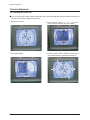
3-4-1 Adjusting the Picture Size
■ Since the K16A chassis includes a deflection adjustment of the Factory Data, adjustments must be performed according to the
following procedures when replacing the Main Board.
1. Display the Lion pattern.
2. Press "Power Off → Mute → 1 → 8 → 2 → Power On"
using the remote control and enter Factory Mode.
3. Enter Deflection Mode.
4. Adjust the V-AMP, V-SHIFT, H-AMP and H-SHIFT items so
that the width becomes 5 and the height becomes 4.
3-10
Samsung Electronics
Alignment & Adjustment
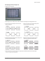
3-4-2 Adjusting the Picture Straight Lines
1. Display the Cross Hatch pattern.
2. Adjust settings other than V-AMP, V-SHIFT, H-AMP and H-SHIFT so that straight lines are displayed without curves.
3. Adjust BOW and the Angle settings so that the center line
becomes a straight line.
4. Adjust the H-Parabola and H-Trapezium settings so that
the left and right lines become straight.
5. Adjust the Upper Corner and the Low Corner settings so that
the end of the lines become straight.
6. Adjust the V-Linearity and V-SC settings so that the
intervals of the horizontal lines become uniform.
7. When the adjustments are complete, display the Lion pattern and check that the picture size has not been changed.
If there is no change, finish the adjustments.
Samsung Electronics
3-11
Alignment & Adjustment
3-5 Software Upgrade
3-5-1 Checking the Version of the Software (Analog SW)
1. To enter Service Mode, press the keys on the remote control according to the following sequence. (in Stand-by status)
Mute → 1 → 8 → 2 → Power On
2. When entering Service mode, the software information is displayed at the top of the service mode menu OSD.
ex) T-RHMNSA-1000 20XX/XX/XX
3-12
Samsung Electronics
Alignment & Adjustment
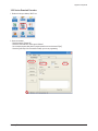
3-5-2 Service Download Procedure
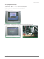
1. Double click the your desktop “WISP” icon.
2. Check the standard
- Check the appoint "Picasso N2"
- Check the "Flash selection" item is appoint "Manual"
- You can adjust program delay time for program speed but we use the normal "5[ms]"
- Check the green lamp if this is sometime red lamp you can not programming
Samsung Electronics
3-13
Alignment & Adjustment
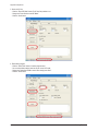
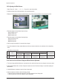
3. Check the IIC line
- Click the “Enter ISP Mode” button For IIC bus line problem or not
- Change the “Press Send to enter ISP Mode”
- Click the “Send” button
4. Erase before program
- Click the “Erase Flash” button for before program erase
- You can select flash selection item but we use normal “All” mode
- Change the “Select flash ROM to erase. When ready press Send.”
- Click the “Send” button
3-14
Samsung Electronics
Alignment & Adjustment
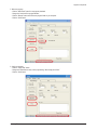
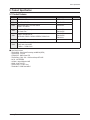
5. Write new program
- Click the “Write Flash” button for new program download
- Change the “Load.hex file to program flashes.”
- Click the “Browse” button and find the new program folder in your computer
- Click the “Send” button
6. Verify new program
- Click the “Verify Flash” button
- Change the “Select flash to verify correct programming. When ready press Send.”
- Click the “Send” button
Samsung Electronics
3-15
Alignment & Adjustment
3-6 Replacements & Calibration
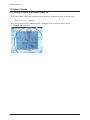
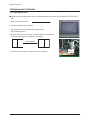
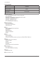
3-6-1 Adjusting the Focus
■ Adjustments must be performed according to the following procedures when replacing the K16A chassis, CRT PCB, FBT or
CRT.
1. Display the Cross Hatch pattern.
2. Set the Screen Adjustment to "Standard".
3. Turn the Static Focus VR clockwise to the maximum position.
(End of clockwise direction)
4. Slowly turn the Static Focus VR counter clockwise so that the center vertical line
is the most clearly displayed. [adjusted point : Center(2/1)]
After Adjustment
5. Check the entire screen focus and repeat steps 3 to 4, if necessary.
Single
Focus VR
3-16
Samsung Electronics
Alignment & Adjustment
3-6-2 Adjusting the Screen Voltage
1. Select "Power Off → Mute → 1 → 8 → 2 → Power On" to enter Service Mode.
2. Initialize all settings to the values appropriate to the corresponding model.
3. Display the Toshiba pattern.
4. First check IBRM in "G2 Adjust" of Factory and adjust Screen VR until the color of IBRM item turns green.
Screen
VR
Samsung Electronics
3-17
Alignment & Adjustment
3-6-3 Adjusting the White Balance
1. Select "Power Off → Mute → 1 → 8 → 2 → Power On" to enter Service Mode.
2. Initialize all settings to the values appropriate to the corresponding model.
3. Display the Toshiba pattern and adjust the White Balance using CA100 with the coordinates of the corresponding model.
4. Enter Video Adjust1 of Service Mode. Adjust Low/Light.
- Adjust Sub Bright to set Y.
- Adjust B Cutoff to set y.
- Adjust R Cutoff to set x.
5. Enter Video Adjust1 of Service Mode. Adjust High/Light.
- Adjust Sub Contrast to set Y.
- Adjust B Drive to set y.
- Adjust R Drive to set x.
6. Check Low/Light and readjust it if its value has been changed.
7. If you have readjusted Low/Light, readjust High/Light until the two values are identical to the coordinates of the corresponding
model.
※ White Balance Standard Data
Model
No
Item
1
White Balance
CL21M21EQ2XXAX
CL21T21EQ2
CL21M21MQ2
CL21M2MQ2
CL21M21MQ2XXAZ
CL21M6MQ2X/XAZ
275/275/50ft
265/265/2.5ft
275/275/50ft
265/265/2.5ft
275/275/47ft
265/265/2.3ft
275/275/47ft
265/265/2.3ft
Required Adjustment
White Balance
(Standard Data)
3-6-4 Check List for the Screen Voltage and White Balance Adjustment
1. The Screen Voltage and White Balance are connected each other, and both of them have to be configured to the correct values.
2. Adjust the White Balance after the Screen Voltage was adjusted, and check if the Screen Voltage is normal after adjusting the
White Balance.
3. If the White Balance is readjusted, check the Screen Voltage again.
4. When the adjustment is finished, check the following checklist.
- If there is a spot on the screen when turning the TV set off/on, adjust the Screen Voltage again.
- If there is a ghost line on the screen, adjust the Screen Voltage again.
3-18
Samsung Electronics
Product Specification
2. Product Specification
2-1 Product Features
Block
CRT
Specfication
Core Parts
29" FLAT AK CRT
GREEN CRT
RF Part
1TUNER F/S TUNER
TDQ-6F/13F2S
Power
WORLD WIDE INPUT VOLTAGE RANGE
STD-BY : 5W UNDER
STR-W6750F
Video
- MULTI SYSTEM(NT/PAL)
- 1H Comb Filter
TDA12005PQ,
TDA12015PQ
Audio
- Output : 5W/10W/15W X2
- BTSC/SAP STEREO : PSEUDO STEREO, TURBO PLUS
TDA12005PQ,
TDA12015PQ,
TDA7297SA
Cabinet
Other
Remark
- 29" CABINET
- BASIC MODEL : CL29M21FQ2XXAX
- UOC3 with a built-in MSP
- TURBO → TURBO PLUS
■ Core Parts Functions
- TDA12005PQ : Video/Sound Processing and MICOM (NTSC)
- TDA12015PQ : Tri-noma
- STR-W6750F : SMPS Power STR
- TDA7297SA(or 7266) : 5W ~ 15W Sound Output BTL AMP
- 24C16 : 16K EEPROM
- LA78040 : Vertical Deflection AMP
- C5936 : H-OUT S/W TR
- TDA-6F/13F2S : F/S PAL Tuner
- TDA6108AJF : R/G/B Drive AMP IC
Samsung Electronics
2-1
Product Specification
2-2 Key Features
Model
CL-29M40MQ
Voltage
AC100-240V
Frequency of Operation
50/60 Hz
Power Consumption
110 Watts
Dimensions (mm)
784 X 503 X 590.5
Weight (Kg/ lbs)
41/90.39
■ Hardware Configuration
- 1 Chip : UOC3 TDA12005PQ(CHROMA, IF+Deflection, MICOM, MSP)
- Tuner : TDA-6F/13F2S
- SOUND AMP : TDA7297SA(ZIP, 15P, -, DUAL, 32dB, PLASTIC, 20V, 30W)
- SMPS Controller : STR-W6750F(6P, TO-3P-F7L)
- Vertical AMP : LA78045(TO220, 7P, 15V)
- Flyback Trans : FOK14B001(11P, 27KV)
- CRT : A51QDX993X(A) (AK, 1H Single Focus)
■ Software Configuration
- MCU : 80C51-controller core
- Data Capture for US Closed Caption
- 0.4883s machine cycle
■ Picture
- Enhance : DNIe Jr.(Digital Natural Image Engine)
- System : NTSC3.58
- Interlaced(60Hz)
- AKB(Auto Kinetic Bais)
- Comb Filter : 1H Comb Filter
- 4:3/Zoom
■ Sound
- BTSC/SAP-STEREO
- Output : 5/10/15W X 2CH
- Auto Stereo, Sound Equalizer, Auto Mute, Auto Volume Limit, PSEUDO STEREO, TURBO PLUS
■ Feature
- Composite (RCA A/V, DVD), S-Video(Y/C)
- Picture Size : Zoom/4:3
- Auto Serch
- Sleep Timer : 180 Min
- Clock Setting
- Blue Screen, Melody On-Off, Picture Mode Select
■ In/Out Terminals
- Rear : 2RCA/DVD/S-VHS
- Front or Side A/V Input(Side A/V Preferability)
■ Remocon
- Universal Interface TM85
■ Power Consumption : 105W
2-2
Samsung Electronics
Product Specification
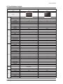
2-3 Specifications Analysis
Model
CL29M21PQ
CL-29M40MQ
Chassis
KS7A
K16A
Design
Picture
Sound
Convenience
Voltage
Jacks
Screen Size
29"
29"
Pure Flat CRT
○
○
DNIe Jr.
○
○
Comb Filter
1H
1H
Velocity Modulation
×
×
Video Noise Reduction
○
○
Auto Kinetic Bias
○
○
Color Tone Control
○
○
Tilt Control
×
×
Picture Mode
4 Mode
4 Mode
MTS/SAP
○
○
Output Power(RMS)
15W x 2
15W x 2
Tweeter
×
×
BBE
×
×
Surround
Surround
Surround
Sound Mode
5 Mode
5 Mode
Graphic Equalizer
×
×
Sub-Woofer Speaker
×
×
Auto Volume Leveler
○
○
Melody On/Off
○
○
Turbo Sound
○
○
PIP
2T (Optional)
×
Plug & Play
○
○
Zoom Mode
○
○
OSD Demo
○
○
OSD Language
E/F/S
E/F/S
Previous Channel
○
○
Closed Caption
○
○
On/Off Timer
○
○
Sleep Timer
○
○
Auto Power Off
○
○
Clock
○
○
Channel Scan
×
×
Self-diagnostic System
○
○
Remote Control
TM76
TM75
Remote Surf
○
○
Channel Labelling
○
○
Blue Screen
○
○
Rack
×
×
Voltage
AC100-240V
AC120V (Mexico)
AC100-240V
Stand-by
under 3W
under 5W
RF Input
R1
R1
A/V Input
S1/R2
S1/R2
Monitor Output
R1
R1
S-VHS Input
R1
R1
Headphone
S1
S1
DVD Input
○
○
PC Input(VGA)
×
×
Samsung Electronics
2-3
Product Specification
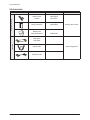
2-4 Accessories
Accessories that can be purchased
additionally
Supplied Accessories
Accessories
2-4
Item
Item code
Remote Control
Batteries
AA59-00385A
4301-000121
Owner's Instructions
AA68-03859A
Warranty Card
Safety Guide Manual
AA68-03242F
Video Cable /
Audio Cable
-
Antenna Cable
-
Component Cable
-
Remark
Samsung Service center
Internet shopping mall
Samsung Electronics
Troubleshooting
6. Troubleshooting
6-1 Checkpoints by Error Mode
■ Power LED: Check that the LED works when turning the Master Switch ON/OFF
■ LED Indicators: See table 6-2-1 Basic Troubleshooting: LED Diagnosis on the Front Panel.
■ In case of a power failure or abnormal screen, check the following items.
1) Check that the power cord is correctly connected to a 230V wall outlet.
2) Check that the Master Switch has been pressed.
3) Check that the transmitter is turned on.
4) Check that transmitter device selection is set to TV.
5) Check that the signal cable is properly connected.
6) Check that channel setting has been set.
Samsung Electronics
6-1
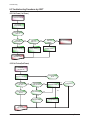
Troubleshooting
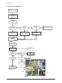
6-1-1 Flow Chart for Malfunction
No Picture & No Sound
Check the AC
voltage impress
Check the master
switch on
Check the
FUSE “FP801S”
Yes
Check the
“D801S” #1
Yes
Check the
IC801S #1
W6750F
Yes
Check the others part
No
No
Change “FP801S”
Yes
Change “IC801S”
Change “D801S”
Yes
Compleat
Repair No Power
No picture & no sound
(1st power OK)
Check the +125V line
Yes
Check the others
B+ line
No
“D811”(D805A) open
and check
No
Change the “D805A”
(D805A)
Yes
Yes
T444 B+ Pin #3
Open and check
Check the +125V line
others part
No
Yes
Check the “Q401”
IC601
IC901
IC201S
TU01S
No
Change the “Q401”
Compleat
repair no power
IC802
IC803
Q401S
IC804
LED
Power cord
6-2
T401S
IC801S
QE01 IC301S
Samsung Electronics
Troubleshooting
6-2 Troubleshooting Procedures by Error Modes
6-2-1 Basic Troubleshooting: Diagnosis of LED on the Front Panel
● : Light is On
◑ : Light is Blinking
○ : Light is Off
Power
Description
○
This happens when the Master Switch is not pressed or the power cord is disconnected.
●
This happens when the power cord is connected and the power switch is pressed.
If you cannot set the power switch on by pressing it, check the power switch Ass'y.
○→◑→●
If you press the power switch of the transmitter or the channel key on the remote control when in
St-BY status, the screen will be turned on.
If the LED blinks and the screen is not displayed, check the connection between the Control
Assy and the Main Board.
6-2-2 Troubleshooting by the Checksum
■ Diagnosis of trouble by the checksum is neither reliable nor convenient.
You can only use the checksume of the current direct-view TV to determine whether the software is corrupted or not.
The Checksum value is determined according to the version of the software loaded on the set.
Therefore, you can determine whether the software has been properly downloaded, if you know the correct checksum for that
version of the software.
You can check the checksum according in the following order.
Factory Mode → Checksum → Right Button → Calculate Checksum → Output Checksum (e.g. 3036)
■ Checksum Examples
T-TR2PEU-1000 : checksum = 8036
T-TR2PEU-1010 : checksum = B612
Samsung Electronics
6-3
Troubleshooting
6-3 Troubleshooting Procedures by ASS'Y
6-3-1 No Power (1st Power)
No Picture & No Sound
Check the AC
voltage impress
Check the master
switch on
Check the
FUSE “FP801S”
Check the
“D801S” #1
Yes
Yes
Check the
IC801S #1
W6750F
Yes
Check the others part
No
No
Change “FP801S”
Yes
Change “IC801S”
Change “D801S”
Yes
Compleat
Repair No Power
6-3-2 No Picture(2nd Power)
No picture
(1st power OK)
Check the +125V line
Yes
Check the others
B+ line
No
“D811”(D811A) open
and check
No
Change the “D811”
(D811A)
Yes
T444 B+ Pin #3
Open and check
Yes
Yes
Check IC501 Pin#6
Change IC201
No
Check the “Q401”
No
Yes
No
Change the “Q401”
Change IC501
Compleat
repair no picture
6-4
Samsung Electronics
Troubleshooting
6-3-3 No Sound
No sound
(1st power OK)
Check the +14V line
No
Yes
Check FD801S
(FD802S)
No
Change FD801S
(FD802S)
Check D807
Yes
Yes
Check IC201 Pin#58,59
Change IC201
No
Check IC601 Pin#6
Yes
No
Change IC601”
Compleat
repair no sound
IC601
IC901
IC201S
IC802
IC803
Q401S
IC804
LED
Power cord
Samsung Electronics
TU01S
T401S
IC801S
QE01 IC301S
6-5
MEMO
6-6
Samsung Electronics
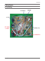
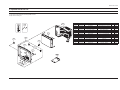
Wiring Diagram
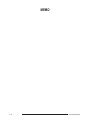
8. Wiring Diagram
8-1 Overall Wiring
PIP MODULE
SPEAKER
AV PCB
CRT SIGNAL
& POWER
CONTROL PCB
POWERSWITCH
Samsung Electronics
8-1
Wiring Diagram
8-2 Pin Connection
CN 503
CN 901
P i n N O. P i n N am e
CN 902
P i n N O.
P i n N am e
1
ST D - L E D
2
T IM E - L E D
3
GN D
4
V CC
5
I.R
P i n N O.
P i n N am e
1
B - OU T
1
K EY - IN 2
2
G- OU T
2
K EY - IN 1
3
R- O U T
3
GN D
4
GN D
K EY - IN 3
5
SE N SE
6
GN D
7
N .C
N O.
4
FN 01
P i n N am e
Pin
P i n N am e
8
GN D
1
R+ OU T
CN P01
CN P02
1
T IL T OU T
9
GN D
2
R- O U T
P i n N O. P i n N am e
P i n N O. P i n N am e
2
T IL T OU T
10
N .C
3
L + OU T
1
B+ 8V
1
OSD - R
3
GN D
11
GN D
4
L - OU T
2
B+ 5V
2
OSD - G
4
GN D
12
H EA T ER
3
GN D
3
OSD - B
13
N .C
4
SC L
4
OSD - F / B
14
B+ 200V
5
SD A
6
GN D
7
H - SY N C
8
V - SY N C
7
9
P IP - F / B
8
10
P IP - B
11
P IP - G
12
P IP - R
SU b -
5
CV B S
6
PIP MODULE
GN D
P IP -
CNP01
CV B S
CNP02
N .C
CN 501A
P i n N O.
P i n N am e
1
GN D
2
N .C
3
GN D
4
H EA T ER
5
N .C
6
B+ 200V
CN 900
P i n N O.
P i n N am e
1
SC L
2
GN D
3
B + 3 .3 V
4
SD A
P i n N am e
P i n N O.
P i n N am e
CN 702
1
B - OU T
1
A V 2 - R- I N
P i n N O.
P i n N am e
2
G- OU T
2
A V 2 - L - IN
1
C - OU T
3
R- O U T
3
A V 2 - L - OU T
2
GN D
4
GN D
4
A V 2 - R- O U T
3
Y - OU T
5
SE N SE
5
GN D
4
GN D
6
GN D
6
A V 2 - V - IN
5
C - IN
7
N .C
7
GN D
6
GN D
8
GN D
8
A V 2 - V - OU T
7
Y - IN
P i n N O.
TU02S
CN 701
CN 502
8-2
P i n N O.
CN 601
TU01S
Samsung Electronics
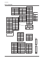
Block Diagram
7. Block Diagram
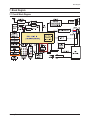
7-1 Overall Block Diagram
Samsung Electronics
7-1
Block Diagram
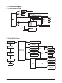
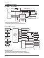
7-2 Partial Block Diagram
7-2-1 Deflection Block Diagram
7-2-2 Power Block Diagram
Switching IC
(FREEW6750F)
15V
SOUND AMP IC B+
EEPROM
13V
BRIDGE DIODE
Mai n -Tr an s
(15W:4950 Type)
(7W:3942 Type)
DS9951
line-filter
8V
IC-REG.(78R08)
IC-REG.(78R33)
UOC3 IC
3.3V
KEY MATRIX
H.D.T B+
6V
IC-REG.(78R05)
PIP MODULE
5V
TUNER
14.5V
Relay(Option)
125V
VERTICAL IC
-13.5V
VIDEO AMP
AC Input
100~240Volts
FBT
180V
6.25Vrms
CRT HEATER
CRT H.V,Focus,
Screen Vol.
7-2
Samsung Electronics
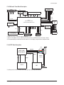
Block Diagram
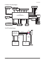
7-2-3 Micom & Tuner Block Diagram
PIP MODULE
(TDA9488X)
IF
TUNER
(TDQ-6F/13F2S)
VIDEO-SAW
(M3953)
5V
33V
V-IF
SOUNDSAW
(M9370)
S-IF
5V
AV1,AV2,S-VIDEO,MOMITOR OUT
S-CASTLE
CVBS1
R/L IN
Y
CVBS2
R/L IN
V_sync
CVBS OUT
R/L OUT
C
R/G/B
SCL/SDA
PIP CVBS OUT
UOC3 IC
(TDA 12005PQ/TDA 12015PQ)
CHROMA /SOUND/MICOM/DEFL ECTION
Y
Pb
Pr
EEPROM
(24C16)
COMPONE
NT
(480i)
R/L OUT
SCL/SDA
SOUND AMP
TDA7297SA
(TDA7266SA)
5V
KEY1
KEY3
5V 8V 3.3V 1.8V
SPEAKER
SENCE
KEY1 MATRIX
(CH UP/DOWN,
VOL UP/DOWN, MENU)
(Y/Pb/Pr)
KEY3 MATRIX
POWER KEY
HEAD-PHONE
H-DRIVE/S-CASTLE
V-DRIVE/V-sync
R/ G / B O U T
7-2-4 CRT Drive Block Diagram
CRT
RK/GK/BK
VIDEO AMP
(TDA6108AJF)
DY HV
B+180V
R G
B
UOC3
Heater
SCREEN
FOCUS
SENCE
FBT
H.V
Samsung Electronics
7-3
MEMO
7-4
Samsung Electronics
Circuit Description
13. Circuit Description
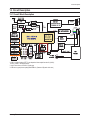
13-1 Overall Block Description
* K16A is a typical analog CRT TV set adapted to New mutiple-function IC (UOC3).
UOC3 = UOC2 + Sound processor.
* Only IF block is out of UOC3 IC. (Split type)
* K16A have a good picture quality,called DNIe Jr. (Gamma & Dynamic skin tone)
Samsung Electronics
13-1
Circuit Description
13-2 Partial Block Description
13-2-1 Deflection Block Description
H-DRIVE
H-deflection TR(ST2001H)
H.D.T
S-CASTLE
H.V
B+15V
UOC3
B-13.5V
FBT
FOCUS
SCREEN
VDP
VDN
V-deflection
V-Sync
(LA78040)
D.Y
PIP MODULE
(TDA9488X)
* Deflection of K16A is same to a typical analog TV set.
* K16A line-up is only 21"F model, so it have not E/W and pin-coushion circuit.
13-2-2 Power Block Description
Switching IC
(FREEW6750F)
15V
SOUND AMP IC B+
EEPROM
13V
BRIDGE DIODE
Mai n -Tr an s
(15W:4950 Type)
(7W:3942 Type)
8V
IC-REG.(78R08)
IC-REG.(78R33)
UOC3 IC
3.3V
KEY MATRIX
H.D.T B+
DS9951
line-filter
6V
IC-REG.(78R05)
PIP MODULE
5V
TUNER
14.5V
125V
VERTICAL IC
Relay(Option)
-13.5V
VIDEO AMP
AC Input
100~240Volts
FBT
180V
6.25Vrms
CRT HEATER
CRT H.V,Focus,
Screen Vol.
* It is the Power circuit of K16A that emphasize sound output level.(15W,10W) so, we use SANKEN Power IC(STR-6750F).
* Main trans have 2pins for sound B+option.
* We use 2types Sound Amp.
(TDA7297SA can output over 10W+10W, TDA7266SA can output under 7W+7W)
* UOC IC need variety power supply, so we use 3type IC vol.regulator. (78R33,78R05,78R08)
13-2
Samsung Electronics
Circuit Description
13-2-3 Micom & Tuner Block Description
PIP MODULE
(TDA9488X)
IF
TUNER
(TDQ-6F/13F2S)
VIDEO-SAW
(M3953)
5V
33V
V-IF
SOUNDSAW
(M9370)
S-IF
5V
AV1,AV2,S-VIDEO,MOMITOR OUT
S-CASTLE
CVBS1
R/L IN
Y
CVBS2
R/L IN
V_sync
CVBS OUT
R/L OUT
C
R/G/B
SCL/SDA
PIP CVBS OUT
UOC3 IC
(TDA 12005PQ/TDA 12015PQ)
CHROMA /SOUND/MICOM/DEFL ECTION
Y
Pb
Pr
EEPROM
(24C16)
COMPONE
NT
(480i)
R/L OUT
SCL/SDA
SOUND AMP
TDA7297SA
(TDA7266SA)
5V
KEY1
KEY3
5V 8V 3.3V 1.8V
SPEAKER
SENCE
KEY1 MATRIX
(CH UP/DOWN,
VOL UP/DOWN, MENU)
(Y/Pb/Pr)
KEY3 MATRIX
POWER KEY
HEAD-PHONE
H-DRIVE/S-CASTLE
V-DRIVE/V-sync
R/ G / B O U T
* TUNER is non-LNA, F/S tuner for analog NTSC CTV.
* UOC3 IC include Micom, chroma, deflection and sound processor. (with DBX fuction),so IC line-up is simple.
* PIP, Component(480i) are switched at the PIP module, so it can't display sub-picture at the Component mode.
13-2-4 CRT Block Description
CRT
RK/GK/BK
VIDEO AMP
(TDA6108AJF)
DY HV
B+180V
Heater
SCREEN
FOCUS
R G
B
UOC3
SENCE
FBT
H.V
* R,G,B output from UOC3 IC is small, so we need high-output video amp(TDA6108AJF).
Samsung Electronics
13-3
MEMO
13-4
Samsung Electronics
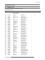
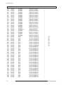
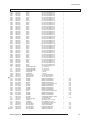
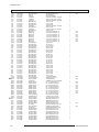
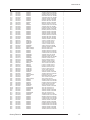
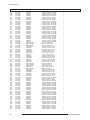
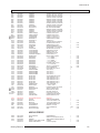
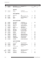
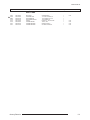
Electrical Part List
5. Electrical Part List
5-1 CL29M40MQ2XXAX
You can search for the updated part code through ITSELF web site.
URL:http://itself.sec.samsung.co.kr
Loc.No.
Code No.
Description
Specification
Q'ty
SA/SNA
S.N.A
Remark
ASSY CHASSIS
M0017
AA91-10472E
ASSY CHASSIS
CL29M40MQ2XXAX
1
M0014
C101
C102
C103
C104
C105
C106
C109
C110
C125
C130
C131
C132
C133
C137
C139
C140
C143
C144
C145
C146
C147
C148
C202
C204
C205
C206
C218
C219
C301
C302
C304
C305
C306
C312
C313
C401
C402
C403
C404
C405
C407
C408
C409
C410
C411
C412
C413
C414
C417
C419
C424
C498
C501
C502
C503
C504
C505
C506
C507
C508
C509
AA94-16007C
2202-002037
2401-003578
2202-002037
2401-000302
2401-000480
2202-002037
2401-003036
2202-002037
2202-002037
2305-000412
2305-000412
2305-000412
2305-000665
2401-000660
2401-000660
2305-000665
2202-000222
2202-000127
2306-000134
2401-000480
2202-000807
2305-000289
2401-003517
2202-002037
2202-002037
2401-000050
2401-000050
2202-002037
2301-000342
2201-000192
2401-000365
2305-000285
2201-000003
2202-000796
2202-000796
2301-000383
2401-000302
2201-000599
2305-000382
2301-001338
2401-002268
2201-000556
2401-001397
2401-002288
2201-000556
2401-001527
2201-000556
2301-001083
2202-000796
2305-000665
2201-000132
2305-000237
2001-000281
2001-000281
2001-000281
2301-001259
2202-000825
2401-000430
2401-000430
2201-000723
2201-002147
ASSY PCB MAIN
C-CERAMIC,MLC-AXIAL
C-AL
C-CERAMIC,MLC-AXIAL
C-AL
C-AL
C-CERAMIC,MLC-AXIAL
C-AL
C-CERAMIC,MLC-AXIAL
C-CERAMIC,MLC-AXIAL
C-FILM,LEAD-PEF
C-FILM,LEAD-PEF
C-FILM,LEAD-PEF
C-FILM,LEAD-PEF
C-AL
C-AL
C-FILM,LEAD-PEF
C-CERAMIC,MLC-AXIAL
C-CERAMIC,MLC-AXIAL
C-FILM,LEAD-PPF
C-AL
C-CERAMIC,MLC-AXIAL
C-FILM,LEAD-PEF
C-AL
C-CERAMIC,MLC-AXIAL
C-CERAMIC,MLC-AXIAL
C-AL
C-AL
C-CERAMIC,MLC-AXIAL
C-FILM,LEAD-PEF
C-CERAMIC,DISC
C-AL
C-FILM,LEAD-PEF
C-CERAMIC,DISC
C-CERAMIC,MLC-AXIAL
C-CERAMIC,MLC-AXIAL
C-FILM,LEAD-PEF
C-AL
C-CERAMIC,DISC
C-FILM,LEAD-PEF
C-FILM,LEAD-OTHER
C-AL
C-CERAMIC,DISC
C-AL
C-AL
C-CERAMIC,DISC
C-AL
C-CERAMIC,DISC
C-FILM,LEAD-PPF
C-CERAMIC,MLC-AXIAL
C-FILM,LEAD-PEF
C-CERAMIC,DISC
C-FILM,LEAD-PEF
R-CARBON
R-CARBON
R-CARBON
C-FILM,LEAD-PPF
C-CERAMIC,MLC-AXIAL
C-AL
C-AL
C-CERAMIC,DISC
C-CERAMIC,DISC
CL29M40MQ2XXAX
100nF,80-20%,50V,Y5V
1000uF,20%,10V,GP,TP,8x20mm,5
100nF,80-20%,50V,Y5V
100uF,20%,25V,GP,TP,6.3x11,5
10uF,20%,50V,GP,TP,5x11,5
100nF,80-20%,50V,Y5V
100uF,20%,16V,GP,TP,5X11mm,5mm
100nF,80-20%,50V,Y5V
100nF,80-20%,50V,Y5V
470nF,5%,63V,TP,-,5mm
470nF,5%,63V,TP,-,5mm
470nF,5%,63V,TP,-,5mm
100nF,5%,63V,TP,7.5x4.0x
2.2uF,20%,50V,GP,TP,5x11,5
2.2uF,20%,50V,GP,TP,5x11,5
100nF,5%,63V,TP,7.5x4.0x
3.3nF,20%,16V,Y5P,TP
10nF,+80-20%,25V,Y5V
150nF,5%,400V,TP,19x17x1
10uF,20%,50V,GP,TP,5x11,5
22nF,+80-20%,25V,Y5V
220nF,5%,63V,TP,-,5mm
22uF,20%,50V,LZ,TP,5x11mm,5
100nF,80-20%,50V,Y5V
100nF,80-20%,50V,Y5V
10uF,20%,16V,GP,TP,5x11,2.5
10uF,20%,16V,GP,TP,5x11,2.5
100nF,80-20%,50V,Y5V
2.2nF,5%,50V,TP,7.4x3.9x
0.01nF,0.25pF,500V,C0G,-,
100uF,20%,50V,WT,TP,10x12.5mm,
220NF,5%,100V,TP,10.5X5.
0.068NF,10%,2KV,SL,TP,7X5
1NF,10%,50V,Y5P,TP,3
1NF,10%,50V,Y5P,TP,3
10nF,5%,50V,TP,6x7x3.2mm
100uF,20%,25V,GP,TP,6.3x11,5
0.56NF,10%,500V,Y5P,TP,5.
4.7nF,5%,400V,TP,-,5mm
0.68NF,5%,1.6KV,BK,28X
2.2uF,20%,250V,LZ,TP,8X11,5
0.47NF,10%,500V,Y5P,TP,5.
470uF,20%,25V,GP,TP,10x16,5
470uF,20%,25V,WT,TP,10x20,5
0.47NF,10%,500V,Y5P,TP,5.
47uF,20%,250V,HR,TP,13x25mm,5m
0.47NF,10%,500V,Y5P,TP,5.
27nF,5%,400V,TP,20x7.5x1
1NF,10%,50V,Y5P,TP,3
100nF,5%,63V,TP,7.5x4.0x
0.1NF,10%,500V,Y5P,TP,6.5
1uF,5%,63V,TP,7.5x15.5mm
100OHM,5%,1/8W,AA,TP,1.8X3.2MM
100OHM,5%,1/8W,AA,TP,1.8X3.2MM
100OHM,5%,1/8W,AA,TP,1.8X3.2MM
100nF,5%,400V,TP,19x8x16
680pF,10%,50V,Y5P,TP
10uF,20%,250V,GP,TP,10x16mm,5m
10uF,20%,250V,GP,TP,10x16mm,5m
4.7NF,20%,3KV,Y5U,TP,16X5
2.7NF,10%,500V,Y5P,TP,10X
1
1
1
1
1
1
1
1
1
1
1
1
1
1
1
1
1
1
1
1
1
1
1
1
1
1
1
1
1
1
1
1
1
1
1
1
1
1
1
1
1
1
1
1
1
1
1
1
1
1
1
1
1
1
1
1
1
1
1
1
1
1
Samsung Electronics
5-1
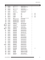
Electrical Part List
Loc.No.
C510
C511
C601
C602
C607
C608
C610
C611
C612
C613
C620
C621
C627
C629
C638
C642
C643
C644
C701
C702
C703
C704
C705
C713
C715
C717
C719
C721
C722
C723
C724
C725
C801
C803
C807
C808
C809
C810
C811
C812
C815
C817
C818
C819
C820
C821
C822
C823
C824
C825
C826
C828
C830
C843
C844
C845
C846
C888
C901
C902
C903
C904
C905
C906
C907
C908
C909
C910
C911
C912
C913
C914
C915
C916
C917
C918
C919
5-2
Code No.
2201-002147
2401-000553
2401-001914
2401-001914
2202-000231
2202-000231
2301-000289
2301-000289
2401-001914
2401-001914
2305-000665
2401-003139
2202-000231
2202-000231
2202-000231
2202-000231
2202-000231
2202-000231
2202-000243
2202-000243
2202-000243
2202-000243
2202-000243
2305-000289
2305-000289
2305-000289
2305-000289
2401-000660
2401-000660
2202-002037
2202-002037
2202-002037
2301-000383
2401-002251
2301-001342
2401-003046
2301-000111
2301-000383
2401-002463
2401-002075
2401-003224
2401-000703
2201-000556
2401-003141
2201-000406
2401-000262
2401-000262
2201-000291
2305-000289
2401-003224
2401-000302
2201-000374
2305-000412
2301-000192
2301-000356
2201-000599
2401-000698
2201-000556
2401-002144
2202-000796
2401-003036
2202-002037
2401-002463
2401-000050
2202-002037
2401-003036
2202-002037
2401-003036
2202-002037
2401-003036
2202-002037
2202-002037
2401-003036
2202-002037
2202-002037
2401-003036
2401-003036
Description
C-CERAMIC,DISC
C-AL
C-AL
C-AL
C-CERAMIC,MLC-AXIAL
C-CERAMIC,MLC-AXIAL
C-FILM,LEAD-PEF
C-FILM,LEAD-PEF
C-AL
C-AL
C-FILM,LEAD-PEF
C-AL
C-CERAMIC,MLC-AXIAL
C-CERAMIC,MLC-AXIAL
C-CERAMIC,MLC-AXIAL
C-CERAMIC,MLC-AXIAL
C-CERAMIC,MLC-AXIAL
C-CERAMIC,MLC-AXIAL
C-CERAMIC,MLC-AXIAL
C-CERAMIC,MLC-AXIAL
C-CERAMIC,MLC-AXIAL
C-CERAMIC,MLC-AXIAL
C-CERAMIC,MLC-AXIAL
C-FILM,LEAD-PEF
C-FILM,LEAD-PEF
C-FILM,LEAD-PEF
C-FILM,LEAD-PEF
C-AL
C-AL
C-CERAMIC,MLC-AXIAL
C-CERAMIC,MLC-AXIAL
C-CERAMIC,MLC-AXIAL
C-FILM,LEAD-PEF
C-AL
C-FILM,LEAD-PPF
C-AL
C-FILM,LEAD-PEF
C-FILM,LEAD-PEF
C-AL
C-AL
C-AL
C-AL
C-CERAMIC,DISC
C-AL
C-CERAMIC,DISC
C-AL
C-AL
C-CERAMIC,DISC
C-FILM,LEAD-PEF
C-AL
C-AL
C-CERAMIC,DISC
C-FILM,LEAD-PEF
C-FILM,LEAD-PEF
C-FILM,LEAD-PEF
C-CERAMIC,DISC
C-AL
C-CERAMIC,DISC
C-AL
C-CERAMIC,MLC-AXIAL
C-AL
C-CERAMIC,MLC-AXIAL
C-AL
C-AL
C-CERAMIC,MLC-AXIAL
C-AL
C-CERAMIC,MLC-AXIAL
C-AL
C-CERAMIC,MLC-AXIAL
C-AL
C-CERAMIC,MLC-AXIAL
C-CERAMIC,MLC-AXIAL
C-AL
C-CERAMIC,MLC-AXIAL
C-CERAMIC,MLC-AXIAL
C-AL
C-AL
Specification
2.7NF,10%,500V,Y5P,TP,10X
1uF,10%,50V,GP,TP,5x11,5
1uF,20%,50V,BP,TP,5x11,5
1uF,20%,50V,BP,TP,5x11,5
0.33NF,10%,50V,Y5P,T
0.33NF,10%,50V,Y5P,T
5.6nF,5%,50V,TP,7x6x3mm,
5.6nF,5%,50V,TP,7x6x3mm,
1uF,20%,50V,BP,TP,5x11,5
1uF,20%,50V,BP,TP,5x11,5
100nF,5%,63V,TP,7.5x4.0x
1000uF,20%,25V,WT,TP,10*20,5mm
0.33NF,10%,50V,Y5P,T
0.33NF,10%,50V,Y5P,T
0.33NF,10%,50V,Y5P,T
0.33NF,10%,50V,Y5P,T
0.33NF,10%,50V,Y5P,T
0.33NF,10%,50V,Y5P,T
33pF,5%,50V,SL,TP,3.
33pF,5%,50V,SL,TP,3.
33pF,5%,50V,SL,TP,3.
33pF,5%,50V,SL,TP,3.
33pF,5%,50V,SL,TP,3.
220nF,5%,63V,TP,-,5mm
220nF,5%,63V,TP,-,5mm
220nF,5%,63V,TP,-,5mm
220nF,5%,63V,TP,-,5mm
2.2uF,20%,50V,GP,TP,5x11,5
2.2uF,20%,50V,GP,TP,5x11,5
100nF,80-20%,50V,Y5V
100nF,80-20%,50V,Y5V
100nF,80-20%,50V,Y5V
10nF,5%,50V,TP,6x7x3.2mm
470uF,20%,200V,GP,BK,25x40mm,1
1.5nF,5%,800V,TP,15x6.5x
47uF,20%,50V,WT,TP,6.3x11,2.5
1.8nF,5%,50V,TP,6.5x3.0x
10nF,5%,50V,TP,6x7x3.2mm
470uF,20%,16V,GP,TP,8x11.5,5
4.7uF,20%,50V,GP,TP,5x11,5
470uF,20%,16V,WT,TP,8X11.5,5mm
2200uF,20%,25V,GP,-,12.5x25mm,
0.47NF,10%,500V,Y5P,TP,5.
2200uF,20%,25V,WT,TP,13x25,5mm
0.27NF,10%,2KV,Y5P,TP,6.3
100uF,20%,160V,HR,TP,16x25,7.5
100uF,20%,160V,HR,TP,16x25,7.5
1NF,10%,500V,Y5P,TP,7.5X3
220nF,5%,63V,TP,-,5mm
470uF,20%,16V,WT,TP,8X11.5,5mm
100uF,20%,25V,GP,TP,6.3x11,5
0.22NF,5%,50V,C0G,TP,10.5
470nF,5%,63V,TP,-,5mm
1nF,5%,50V,TP,5.3x10mm,5
47nF,5%,50V,TP,7.5x4.0x6
0.56NF,10%,500V,Y5P,TP,5.
2200uF,20%,16V,WT,TP,12.5x25,5
0.47NF,10%,500V,Y5P,TP,5.
47uF,20%,16V,GP,TP,5x11,5
1NF,10%,50V,Y5P,TP,3
100uF,20%,16V,GP,TP,5X11mm,5mm
100nF,80-20%,50V,Y5V
470uF,20%,16V,GP,TP,8x11.5,5
10uF,20%,16V,GP,TP,5x11,2.5
100nF,80-20%,50V,Y5V
100uF,20%,16V,GP,TP,5X11mm,5mm
100nF,80-20%,50V,Y5V
100uF,20%,16V,GP,TP,5X11mm,5mm
100nF,80-20%,50V,Y5V
100uF,20%,16V,GP,TP,5X11mm,5mm
100nF,80-20%,50V,Y5V
100nF,80-20%,50V,Y5V
100uF,20%,16V,GP,TP,5X11mm,5mm
100nF,80-20%,50V,Y5V
100nF,80-20%,50V,Y5V
100uF,20%,16V,GP,TP,5X11mm,5mm
100uF,20%,16V,GP,TP,5X11mm,5mm
Q'ty
SA/SNA
Remark
1
1
1
1
1
1
1
1
1
1
1
1
1
1
1
1
1
1
1
1
1
1
1
1
1
1
1
1
1
1
1
1
1
1
1
1
1
1
1
1
1
1
1
1
1
1
1
1
1
1
1
1
1
1
1
1
1
1
1
1
1
1
1
1
1
1
1
1
1
1
1
1
1
1
1
1
1
Samsung Electronics
Electrical Part List
Loc.No.
Code No.
C920
C921
C922
C924
C925
C926
C927
C928
C929
C930
C931
CIS1
CIS1
CIS1
CIS1
CIS1
CIS1
CIS1
CIS1
CIS3
CN330
CN330
CN330
CN330
CN330
CN330
CN909
CP01
CR402S
CR403S
CR404S
CR406S
CV113
CV114
CX801S
CY802S
D101
D201
D303
D305
D401
D402
D403
D404
D405
D406
D407
D408
D409
D501
D502
D503
D504
D510
D511
D512
D513
D606
D630
D631
D801S
D803
D804
D805
D807
D808
D809A
D811
D813
DZ242
DZ301
DZ302
DZ303
DZ305
DZ306
DZ403
DZ501
2202-002037
2401-003578
2401-003036
2202-002037
2401-000050
2202-002037
2401-003036
2301-000383
2301-000301
2401-000553
2202-002037
0205-001154
0205-001154
0205-001154
0205-001154
0205-001154
0205-001154
0205-001154
0205-001154
AA40-00016A
3711-001084
3711-003043
3711-003241
3711-002643
3711-002645
3711-002647
AA37-00001A
2201-000146
2306-000329
2301-001456
2303-000296
2306-000195
2202-000127
2202-000127
2306-000318
2201-000446
0401-000005
0401-000005
0402-000546
0401-000005
0402-000537
0402-000132
0402-000132
0402-001599
0402-000534
0402-000540
0402-000540
0402-001295
0401-000005
0401-000006
0401-000006
0401-000006
0402-000546
0401-000005
0401-000005
0401-000005
0401-000005
0401-000005
0401-000005
0401-000005
0402-001477
0402-000546
0401-000006
0401-000006
0402-001604
0402-000132
AA96-00243D
0402-001603
0402-000493
0403-001318
0403-001329
0403-001329
0403-001221
0403-001329
0403-000700
0401-000005
0403-000720
Samsung Electronics
Description
C-CERAMIC,MLC-AXIAL
C-AL
C-AL
C-CERAMIC,MLC-AXIAL
C-AL
C-CERAMIC,MLC-AXIAL
C-AL
C-FILM,LEAD-PEF
C-FILM,LEAD-PEF
C-AL
C-CERAMIC,MLC-AXIAL
OIL-SILICON
OIL-SILICON
OIL-SILICON
OIL-SILICON
OIL-SILICON
OIL-SILICON
OIL-SILICON
OIL-SILICON
TUNER
HEADER-BOARD TO CABLE
HEADER-BOARD TO CABLE
HEADER-BOARD TO CABLE
HEADER-BOARD TO CABLE
HEADER-BOARD TO CABLE
HEADER-BOARD TO CABLE
CONNECTOR-FBT FIX PIN
C-CERAMIC,DISC
C-FILM,LEAD-PPF
C-FILM,LEAD-OTHER
C-FILM,LEAD-PPF
C-FILM,LEAD-PPF
C-CERAMIC,MLC-AXIAL
C-CERAMIC,MLC-AXIAL
C-FILM,LEAD-PPF
C-CERAMIC,DISC
DIODE-SWITCHING
DIODE-SWITCHING
DIODE-RECTIFIER
DIODE-SWITCHING
DIODE-RECTIFIER
DIODE-RECTIFIER
DIODE-RECTIFIER
DIODE-RECTIFIER
DIODE-RECTIFIER
DIODE-RECTIFIER
DIODE-RECTIFIER
DIODE-RECTIFIER
DIODE-SWITCHING
DIODE-SWITCHING
DIODE-SWITCHING
DIODE-SWITCHING
DIODE-RECTIFIER
DIODE-SWITCHING
DIODE-SWITCHING
DIODE-SWITCHING
DIODE-SWITCHING
DIODE-SWITCHING
DIODE-SWITCHING
DIODE-SWITCHING
DIODE-BRIDGE
DIODE-RECTIFIER
DIODE-SWITCHING
DIODE-SWITCHING
DIODE-RECTIFIER
DIODE-RECTIFIER
ASSY HEAT SINK P
DIODE-RECTIFIER
DIODE-RECTIFIER
DIODE-ZENER
DIODE-ZENER
DIODE-ZENER
DIODE-ZENER
DIODE-ZENER
DIODE-ZENER
DIODE-SWITCHING
DIODE-ZENER
Specification
100nF,80-20%,50V,Y5V
1000uF,20%,10V,GP,TP,8x20mm,5
100uF,20%,16V,GP,TP,5X11mm,5mm
100nF,80-20%,50V,Y5V
10uF,20%,16V,GP,TP,5x11,2.5
100nF,80-20%,50V,Y5V
100uF,20%,16V,GP,TP,5X11mm,5mm
10nF,5%,50V,TP,6x7x3.2mm
6.8nF,5%,50V,TP,6.5X5.5X
1uF,10%,50V,GP,TP,5x11,5
100nF,80-20%,50V,Y5V
G746,-,G746,-,G746,-,G746,-,G746,-,G746,-,G746,-,G746,-,TDQ-6F/13F2S,NTSC,181CH,45.75MHZ,7
BOX,8P,1R,2.5MM,ST
BOX,4P,1R,2.5MM,ST
BOX,14P,1R,2.5MM,S
BOX,4P,1R,2.5mm,ST
BOX,6P,1R,2.5mm,ST
BOX,8P,1R,2.5mm,ST
JM-3500,CPTTV,0.36
0.1NF,5%,50V,SL,TP,5X3.5M
7NF,3%,1.6KV,BK,28.5X18.
5.1NF,5%,1.6KV,BK,29X9
18nF,5%,630V,BK,20x16x9.
360nF,5%,400V,BK,26x19x1
10nF,+80-20%,25V,Y5V
10nF,+80-20%,25V,Y5V
220nF,20%,275V,BK,26x7x1
3.3NF,20%,400V,Y5U,BK,15X
1N4148,75V,150mA,DO-35,T
1N4148,75V,150mA,DO-35,T
TVR10G,400V,1A,DO-41,TP
1N4148,75V,150mA,DO-35,T
RH1A,600V,0.6A,DO-204AC,
1N4004,400V,1A,DO-41,TP
1N4004,400V,1A,DO-41,TP
DGP30L,1500,3A,DO-201AD(
RG10V,400V,1.2A,DO-201,T
RU20A,600V,1.5A,-,TP
RU20A,600V,1.5A,-,TP
GUR460L-5700,600V,4A,DO1N4148,75V,150mA,DO-35,T
BAV21,250V,200mA,DO-35,T
BAV21,250V,200mA,DO-35,T
BAV21,250V,200mA,DO-35,T
TVR10G,400V,1A,DO-41,TP
1N4148,75V,150mA,DO-35,T
1N4148,75V,150mA,DO-35,T
1N4148,75V,150mA,DO-35,T
1N4148,75V,150mA,DO-35,T
1N4148,75V,150mA,DO-35,T
1N4148,75V,150mA,DO-35,T
1N4148,75V,150mA,DO-35,T
GSIB460,600V,4A,SIP-4,ST
TVR10G,400V,1A,DO-41,TP
BAV21,250V,200mA,DO-35,T
BAV21,250V,200mA,DO-35,T
MUR420,200V,4A,DO-201AD,
1N4004,400V,1A,DO-41,TP
D06U20S,AA62-00045B,BRI
MUR480E,800V,4A,DO-201AD
1R5GU41,400V,1.5A,DO-15L
MTZJ4.3B,4.17-4.43V,500mW,DO
MTZJ24B,22.75-23.73V,500mW,D
MTZJ24B,22.75-23.73V,500mW,D
UZ39BSB,35.36-37.19V,500mW,D
MTZJ24B,22.75-23.73V,500mW,D
TZP33A,5%,1000mW,DO-41,TP
1N4148,75V,150mA,DO-35,T
MTZJ9.1B,8.57-9.01V,500mW,DO
Q'ty
1
1
1
1
1
1
1
1
1
1
1
0.1
0.1
0.1
0.1
0.2
0.2
0.2
0.2
1
1
1
1
1
1
1
1
1
1
1
1
1
1
1
1
1
1
1
1
1
1
1
1
1
1
1
1
1
1
1
1
1
1
1
1
1
1
1
1
1
1
1
1
1
1
1
1
1
1
1
1
1
1
1
1
1
1
SA/SNA
Remark
S.N.A
S.N.A
S.N.A
S.N.A
S.N.A
S.N.A
S.N.A
S.N.A
S.N.A
5-3
Electrical Part List
Loc.No.
DZ502
DZ503
DZ510
DZ605
DZ701
DZ702
DZ703
DZ704
DZ705
DZ707
DZ708
DZ712
DZ713
DZ714
DZ802
DZ804
DZ807
DZ810
DZ811
DZ812
DZ813
DZ814
DZ815
DZ816
DZ818
DZ819
DZ901
DZ902
DZ903
DZ904
DZ905
EL501
EL502
EL800
EL801
EL803
EL804
EL805
EL806
EL807
EL808
EL809
EY422
EY600
EY601
EY602
EY603
EY800
EY801
EY802
EY803
EY804
EY820
EY821
EY823
EY825
EY826
EY827
EY828
EY829
EY831
EY832
EY833
EY834
EY835
EY836
EY837
EY838
EY839
EY840
EY841
EY842
EY843
EY844
EY845
EY846
EY847
5-4
Code No.
0403-000720
0403-000720
0403-000716
0403-000714
0403-000720
0403-000720
0403-000720
0403-000720
0403-000720
0403-000720
0403-000720
0403-000720
0403-000720
0403-000720
0403-000717
0403-000508
0403-000718
0403-000508
0403-000700
0403-000700
0403-000720
0403-001320
0403-001321
0401-000005
0403-000720
0403-000714
0403-000719
0403-000719
0403-000508
0403-000508
0403-001317
6042-000001
6042-000001
6042-000001
6042-000001
6042-000001
6042-000001
6042-000001
6042-000001
6042-000001
6042-000001
6042-000001
6042-000002
6042-000002
6042-000002
6042-000002
6042-000002
6042-000002
6042-000002
6042-000002
6042-000002
6042-000002
6042-000002
6042-000002
6042-000002
6042-000002
6042-000002
6042-000002
6042-000002
6042-000002
6042-000002
6042-000002
6042-000002
6042-000002
6042-000002
6042-000002
6042-000002
6042-000002
6042-000002
6042-000002
6042-000002
6042-000002
6042-000002
6042-000002
6042-000002
6042-000002
6042-000002
Description
DIODE-ZENER
DIODE-ZENER
DIODE-ZENER
DIODE-ZENER
DIODE-ZENER
DIODE-ZENER
DIODE-ZENER
DIODE-ZENER
DIODE-ZENER
DIODE-ZENER
DIODE-ZENER
DIODE-ZENER
DIODE-ZENER
DIODE-ZENER
DIODE-ZENER
DIODE-ZENER
DIODE-ZENER
DIODE-ZENER
DIODE-ZENER
DIODE-ZENER
DIODE-ZENER
DIODE-ZENER
DIODE-ZENER
DIODE-SWITCHING
DIODE-ZENER
DIODE-ZENER
DIODE-ZENER
DIODE-ZENER
DIODE-ZENER
DIODE-ZENER
DIODE-ZENER
EYELET
EYELET
EYELET
EYELET
EYELET
EYELET
EYELET
EYELET
EYELET
EYELET
EYELET
EYELET
EYELET
EYELET
EYELET
EYELET
EYELET
EYELET
EYELET
EYELET
EYELET
EYELET
EYELET
EYELET
EYELET
EYELET
EYELET
EYELET
EYELET
EYELET
EYELET
EYELET
EYELET
EYELET
EYELET
EYELET
EYELET
EYELET
EYELET
EYELET
EYELET
EYELET
EYELET
EYELET
EYELET
EYELET
Specification
MTZJ9.1B,8.57-9.01V,500mW,DO
MTZJ9.1B,8.57-9.01V,500mW,DO
MTZJ4.7B,4.59-4.77V,500mW,DO
MTZJ3.3B,3.32-3.53V,500mW,DO
MTZJ9.1B,8.57-9.01V,500mW,DO
MTZJ9.1B,8.57-9.01V,500mW,DO
MTZJ9.1B,8.57-9.01V,500mW,DO
MTZJ9.1B,8.57-9.01V,500mW,DO
MTZJ9.1B,8.57-9.01V,500mW,DO
MTZJ9.1B,8.57-9.01V,500mW,DO
MTZJ9.1B,8.57-9.01V,500mW,DO
MTZJ9.1B,8.57-9.01V,500mW,DO
MTZJ9.1B,8.57-9.01V,500mW,DO
MTZJ9.1B,8.57-9.01V,500mW,DO
MTZJ5.1B,4.94-5.2V,500mW,DOMTZJ5.6B,5.45-5.73V,500mW,DO
MTZJ6.8B,6.52-6.79V,500mW,DO
MTZJ5.6B,5.45-5.73V,500mW,DO
TZP33A,5%,1000mW,DO-41,TP
TZP33A,5%,1000mW,DO-41,TP
MTZJ9.1B,8.57-9.01V,500mW,DO
MTZJ6.2C,6.16-6.4V,500mW,DOMTZJ6.8C,6.7-6.97V,500mW,DO1N4148,75V,150mA,DO-35,T
MTZJ9.1B,8.57-9.01V,500mW,DO
MTZJ3.3B,3.32-3.53V,500mW,DO
MTZJ7.5B,7.11-7.44V,500mW,DO
MTZJ7.5B,7.11-7.44V,500mW,DO
MTZJ5.6B,5.45-5.73V,500mW,DO
MTZJ5.6B,5.45-5.73V,500mW,DO
MTZJ3.0B,3.01-3.22V,500mW,DO
ID2.2,OD2.7,L3.1,NI+SN,BSP3-1/2H
ID2.2,OD2.7,L3.1,NI+SN,BSP3-1/2H
ID2.2,OD2.7,L3.1,NI+SN,BSP3-1/2H
ID2.2,OD2.7,L3.1,NI+SN,BSP3-1/2H
ID2.2,OD2.7,L3.1,NI+SN,BSP3-1/2H
ID2.2,OD2.7,L3.1,NI+SN,BSP3-1/2H
ID2.2,OD2.7,L3.1,NI+SN,BSP3-1/2H
ID2.2,OD2.7,L3.1,NI+SN,BSP3-1/2H
ID2.2,OD2.7,L3.1,NI+SN,BSP3-1/2H
ID2.2,OD2.7,L3.1,NI+SN,BSP3-1/2H
ID2.2,OD2.7,L3.1,NI+SN,BSP3-1/2H
ID1.5,OD2,L2.8,NI+SN,BSP3-1/2H
ID1.5,OD2,L2.8,NI+SN,BSP3-1/2H
ID1.5,OD2,L2.8,NI+SN,BSP3-1/2H
ID1.5,OD2,L2.8,NI+SN,BSP3-1/2H
ID1.5,OD2,L2.8,NI+SN,BSP3-1/2H
ID1.5,OD2,L2.8,NI+SN,BSP3-1/2H
ID1.5,OD2,L2.8,NI+SN,BSP3-1/2H
ID1.5,OD2,L2.8,NI+SN,BSP3-1/2H
ID1.5,OD2,L2.8,NI+SN,BSP3-1/2H
ID1.5,OD2,L2.8,NI+SN,BSP3-1/2H
ID1.5,OD2,L2.8,NI+SN,BSP3-1/2H
ID1.5,OD2,L2.8,NI+SN,BSP3-1/2H
ID1.5,OD2,L2.8,NI+SN,BSP3-1/2H
ID1.5,OD2,L2.8,NI+SN,BSP3-1/2H
ID1.5,OD2,L2.8,NI+SN,BSP3-1/2H
ID1.5,OD2,L2.8,NI+SN,BSP3-1/2H
ID1.5,OD2,L2.8,NI+SN,BSP3-1/2H
ID1.5,OD2,L2.8,NI+SN,BSP3-1/2H
ID1.5,OD2,L2.8,NI+SN,BSP3-1/2H
ID1.5,OD2,L2.8,NI+SN,BSP3-1/2H
ID1.5,OD2,L2.8,NI+SN,BSP3-1/2H
ID1.5,OD2,L2.8,NI+SN,BSP3-1/2H
ID1.5,OD2,L2.8,NI+SN,BSP3-1/2H
ID1.5,OD2,L2.8,NI+SN,BSP3-1/2H
ID1.5,OD2,L2.8,NI+SN,BSP3-1/2H
ID1.5,OD2,L2.8,NI+SN,BSP3-1/2H
ID1.5,OD2,L2.8,NI+SN,BSP3-1/2H
ID1.5,OD2,L2.8,NI+SN,BSP3-1/2H
ID1.5,OD2,L2.8,NI+SN,BSP3-1/2H
ID1.5,OD2,L2.8,NI+SN,BSP3-1/2H
ID1.5,OD2,L2.8,NI+SN,BSP3-1/2H
ID1.5,OD2,L2.8,NI+SN,BSP3-1/2H
ID1.5,OD2,L2.8,NI+SN,BSP3-1/2H
ID1.5,OD2,L2.8,NI+SN,BSP3-1/2H
ID1.5,OD2,L2.8,NI+SN,BSP3-1/2H
Q'ty
1
1
1
1
1
1
1
1
1
1
1
1
1
1
1
1
1
1
1
1
1
1
1
1
1
1
1
1
1
1
1
1
1
1
1
1
1
1
1
1
1
1
1
1
1
1
1
1
1
1
1
1
1
1
1
1
1
1
1
1
1
1
1
1
1
1
1
1
1
1
1
1
1
1
1
1
1
SA/SNA
Remark
S.N.A
S.N.A
S.N.A
S.N.A
S.N.A
S.N.A
S.N.A
S.N.A
S.N.A
S.N.A
S.N.A
Samsung Electronics
Electrical Part List
Loc.No.
Code No.
EY848
EY849
EY850
EY851
EY852
EY853
EY854
EY855
EY856
EY857
EY858
EY859
EY860
EY861
EY862
EY863
EY864
EY865
EY866
EY867
EY868
EY869
EY870
EY871
EY872
EY873
EY874
EY875
EY876
EY877
EY878
EY879
EY880
EY881
EY882
EY883
EY887
EY890
EY893
EY898
EY899
EY982
EY983
F101
F101
F101
F101
F801A
F801B
FD801A
FD802
FD802S
GT101
GT102
GT103
GT104
GT301
GT404
GT501
GT502
GT503
GT504
GT801
GT804
GT805
GT806
H/S
H/S
IC012
IC063
IC112
IC201
IC301
IC501
IC601
IC801S
IC802
6042-000002
6042-000002
6042-000002
6042-000002
6042-000002
6042-000002
6042-000002
6042-000002
6042-000002
6042-000002
6042-000002
6042-000002
6042-000002
6042-000002
6042-000002
6042-000002
6042-000002
6042-000002
6042-000002
6042-000002
6042-000002
6042-000002
6042-000002
6042-000002
6042-000002
6042-000002
6042-000002
6042-000002
6042-000002
6042-000002
6042-000002
6042-000002
6042-000002
6042-000002
6042-000002
6042-000002
6042-000002
6042-000002
6042-000002
6042-000002
6042-000002
6042-000002
6042-000002
2901-000297
2901-000297
2901-000297
2901-000299
3602-000114
3602-000114
3601-001228
3601-000281
3601-001163
BH71-40300A
BH71-40300A
BH71-40300A
BH71-40300A
AA60-40012F
BH71-40300A
BH71-40300A
BH71-40300A
BH71-40300A
BH71-40300A
AA60-40012G
BH71-40300A
BH71-40300A
BH71-40300A
0502-001263
AA61-01390A
1203-001217
AA13-00116A
1103-001211
AA09-00508A
AA96-00623F
AA96-50311P
BP96-00418B
AA96-50373P
AA96-00243Q
Samsung Electronics
Description
EYELET
EYELET
EYELET
EYELET
EYELET
EYELET
EYELET
EYELET
EYELET
EYELET
EYELET
EYELET
EYELET
EYELET
EYELET
EYELET
EYELET
EYELET
EYELET
EYELET
EYELET
EYELET
EYELET
EYELET
EYELET
EYELET
EYELET
EYELET
EYELET
EYELET
EYELET
EYELET
EYELET
EYELET
EYELET
EYELET
EYELET
EYELET
EYELET
EYELET
EYELET
EYELET
EYELET
FILTER-EMI ON BOARD
FILTER-EMI ON BOARD
FILTER-EMI ON BOARD
FILTER-EMI ON BOARD
FUSE-HOLDER
FUSE-HOLDER
FUSE-AXIAL LEAD
FUSE-CARTRIDGE
FUSE-AXIAL LEAD
PIN-HINGE
PIN-HINGE
PIN-HINGE
PIN-HINGE
PIN-GT
PIN-HINGE
PIN-HINGE
PIN-HINGE
PIN-HINGE
PIN-HINGE
PIN-GT
PIN-HINGE
PIN-HINGE
PIN-HINGE
TR-POWER
BRACKET
IC-POSI.ADJUST REG.
IC HYBRID
IC-EEPROM
IC MICOM MTP
ASSY HEAT SINK P
ASSY HEAT SINK P
ASSY HEAT SINK P
ASSY HEAT SINK P
ASSY HEAT SINK P
Specification
ID1.5,OD2,L2.8,NI+SN,BSP3-1/2H
ID1.5,OD2,L2.8,NI+SN,BSP3-1/2H
ID1.5,OD2,L2.8,NI+SN,BSP3-1/2H
ID1.5,OD2,L2.8,NI+SN,BSP3-1/2H
ID1.5,OD2,L2.8,NI+SN,BSP3-1/2H
ID1.5,OD2,L2.8,NI+SN,BSP3-1/2H
ID1.5,OD2,L2.8,NI+SN,BSP3-1/2H
ID1.5,OD2,L2.8,NI+SN,BSP3-1/2H
ID1.5,OD2,L2.8,NI+SN,BSP3-1/2H
ID1.5,OD2,L2.8,NI+SN,BSP3-1/2H
ID1.5,OD2,L2.8,NI+SN,BSP3-1/2H
ID1.5,OD2,L2.8,NI+SN,BSP3-1/2H
ID1.5,OD2,L2.8,NI+SN,BSP3-1/2H
ID1.5,OD2,L2.8,NI+SN,BSP3-1/2H
ID1.5,OD2,L2.8,NI+SN,BSP3-1/2H
ID1.5,OD2,L2.8,NI+SN,BSP3-1/2H
ID1.5,OD2,L2.8,NI+SN,BSP3-1/2H
ID1.5,OD2,L2.8,NI+SN,BSP3-1/2H
ID1.5,OD2,L2.8,NI+SN,BSP3-1/2H
ID1.5,OD2,L2.8,NI+SN,BSP3-1/2H
ID1.5,OD2,L2.8,NI+SN,BSP3-1/2H
ID1.5,OD2,L2.8,NI+SN,BSP3-1/2H
ID1.5,OD2,L2.8,NI+SN,BSP3-1/2H
ID1.5,OD2,L2.8,NI+SN,BSP3-1/2H
ID1.5,OD2,L2.8,NI+SN,BSP3-1/2H
ID1.5,OD2,L2.8,NI+SN,BSP3-1/2H
ID1.5,OD2,L2.8,NI+SN,BSP3-1/2H
ID1.5,OD2,L2.8,NI+SN,BSP3-1/2H
ID1.5,OD2,L2.8,NI+SN,BSP3-1/2H
ID1.5,OD2,L2.8,NI+SN,BSP3-1/2H
ID1.5,OD2,L2.8,NI+SN,BSP3-1/2H
ID1.5,OD2,L2.8,NI+SN,BSP3-1/2H
ID1.5,OD2,L2.8,NI+SN,BSP3-1/2H
ID1.5,OD2,L2.8,NI+SN,BSP3-1/2H
ID1.5,OD2,L2.8,NI+SN,BSP3-1/2H
ID1.5,OD2,L2.8,NI+SN,BSP3-1/2H
ID1.5,OD2,L2.8,NI+SN,BSP3-1/2H
ID1.5,OD2,L2.8,NI+SN,BSP3-1/2H
ID1.5,OD2,L2.8,NI+SN,BSP3-1/2H
ID1.5,OD2,L2.8,NI+SN,BSP3-1/2H
ID1.5,OD2,L2.8,NI+SN,BSP3-1/2H
ID1.5,OD2,L2.8,NI+SN,BSP3-1/2H
ID1.5,OD2,L2.8,NI+SN,BSP3-1/2H
-,3A,-,3.5x5mm,TP,-,3A,-,3.5x5mm,TP,-,3A,-,3.5x5mm,TP,-,6A,UL/CSA,-,9x7.5,
-,-,30mohm
-,-,30mohm
125V,10A,FAST-ACTING,EPO
250V,4A,TIME-LAG,GLASS,5.
125V,7A,-,EPOXY,2.4X7.1M
BRASS,D2.36!,HEAT/SINK,SN
BRASS,D2.36!,HEAT/SINK,SN
BRASS,D2.36!,HEAT/SINK,SN
BRASS,D2.36!,HEAT/SINK,SN
4P,2.36PI,6/12/14mm,NYLON66,LOCKI
BRASS,D2.36!,HEAT/SINK,SN
BRASS,D2.36!,HEAT/SINK,SN
BRASS,D2.36!,HEAT/SINK,SN
BRASS,D2.36!,HEAT/SINK,SN
BRASS,D2.36!,HEAT/SINK,SN
3P,2.36PI,10/5mm,NYLON66,LOCKING
BRASS,D2.36!,HEAT/SINK,SN
BRASS,D2.36!,HEAT/SINK,SN
BRASS,D2.36!,HEAT/SINK,SN
FJAF6810A,NPN,60000MW,TP-3PF(FO
CT-29A20HR,SECC,T1.0
431,TO-92,3P,4.58MIL
STR-W6750F,6,-20 to +115,TO-3P
24C16,2Kx8Bit,DIP,8P,10.16x7.1
TDA12005PQ/N1FCO-MTP,CL21M2
LA78045,SCREW,AA62-0005
AA62-30175D,TDA6108AJF,
AA62-30182F,SCREW,TDA72
AA62-30181V,STR-W6750F,
SCREW,AA62-00045A,1203-
Q'ty
1
1
1
1
1
1
1
1
1
1
1
1
1
1
1
1
1
1
1
1
1
1
1
1
1
1
1
1
1
1
1
1
1
1
1
1
1
1
1
1
1
1
1
1
1
1
1
1
1
1
1
1
1
1
1
1
1
1
1
1
1
1
1
1
1
1
1
1
1
1
1
1
1
1
1
1
1
SA/SNA
Remark
S.N.A
S.N.A
S.N.A
S.N.A
S.N.A
S.N.A
S.N.A
S.N.A
S.N.A
S.N.A
S.N.A
S.N.A
S.N.A
S.N.A
S.N.A
S.N.A
S.N.A
S.N.A
S.N.A
S.N.A
S.N.A
5-5
Electrical Part List
Loc.No.
Code No.
IC803
JA333
JA333
JP104
JP105
L101
L102
L103
L107
L108
L201
L202
L204
L2514
L2514
L2514
L2514
L2514
L2514
L2514
L2514
L303B
L424
L503A
L605
L606
L607
L608
L702
L704
L705
L706
L707
L708
L709
L710
L808
L902
L903
L906
L907
L908
L909
L910
L911
LD901
LX801S
M0014
M0018
M0081
M0081
M0081
M0081
M0081
M0081
M0081
M0081
M0081
M2893
P803T
PC801S
Q207
Q261
Q262
Q401
Q403
Q404
Q409
Q501
Q502
Q802
Q805
Q806
Q902
Q903
Q904
Q905
AA96-00243R
3722-001333
3722-001423
2001-000281
2001-000005
2001-000281
2701-000114
2701-000114
2701-000159
2001-000281
2701-000114
2001-000793
2701-000114
3301-000287
3301-000287
3301-000287
3301-000287
3301-000287
3301-000287
3301-000287
3301-000287
2701-001040
2701-000142
2702-001092
2701-000177
2701-000177
2701-000177
2701-000177
2701-000142
2701-000142
2701-000177
2701-000177
2701-000142
2701-000142
2701-000142
2701-000142
2701-001030
2701-000114
2701-000114
2701-000114
2701-000114
2701-000114
2701-000114
2701-000114
2701-000114
AA96-00555A
AA29-00015A
AA97-16499G
AA97-16124C
6003-000335
6003-000335
6003-000333
6003-000334
6003-000334
6003-000333
6003-000334
6003-000333
6003-000335
AA39-00376B
1404-001264
0604-001032
0501-000283
0501-000283
0501-000389
AA96-00624H
0502-001007
AA96-00624G
0505-001723
0501-000389
0501-000389
0501-000389
0501-000389
0501-000389
0501-000389
0501-000283
0501-000283
0501-000389
5-6
Description
ASSY HEAT SINK P
JACK-PIN
JACK-PIN
R-CARBON
R-CARBON
R-CARBON
INDUCTOR-AXIAL
INDUCTOR-AXIAL
INDUCTOR-AXIAL
R-CARBON
INDUCTOR-AXIAL
R-CARBON
INDUCTOR-AXIAL
BEAD-AXIAL
BEAD-AXIAL
BEAD-AXIAL
BEAD-AXIAL
BEAD-AXIAL
BEAD-AXIAL
BEAD-AXIAL
BEAD-AXIAL
INDUCTOR-AXIAL
INDUCTOR-AXIAL
INDUCTOR-RADIAL
INDUCTOR-AXIAL
INDUCTOR-AXIAL
INDUCTOR-AXIAL
INDUCTOR-AXIAL
INDUCTOR-AXIAL
INDUCTOR-AXIAL
INDUCTOR-AXIAL
INDUCTOR-AXIAL
INDUCTOR-AXIAL
INDUCTOR-AXIAL
INDUCTOR-AXIAL
INDUCTOR-AXIAL
INDUCTOR-AXIAL
INDUCTOR-AXIAL
INDUCTOR-AXIAL
INDUCTOR-AXIAL
INDUCTOR-AXIAL
INDUCTOR-AXIAL
INDUCTOR-AXIAL
INDUCTOR-AXIAL
INDUCTOR-AXIAL
ASSY LED GUIDE
FILTER LINE NOISE
ASSY AUTO-MAIN
ASSY MICOM
SCREW-TAPTITE
SCREW-TAPTITE
SCREW-TAPTITE
SCREW-TAPTITE
SCREW-TAPTITE
SCREW-TAPTITE
SCREW-TAPTITE
SCREW-TAPTITE
SCREW-TAPTITE
LEAD CONNECTOR
THERMISTOR-PTC
PHOTO-COUPLER
TR-SMALL SIGNAL
TR-SMALL SIGNAL
TR-SMALL SIGNAL
ASSY HEAT SINK P
TR-POWER
ASSY HEAT SINK P
FET-SILICON
TR-SMALL SIGNAL
TR-SMALL SIGNAL
TR-SMALL SIGNAL
TR-SMALL SIGNAL
TR-SMALL SIGNAL
TR-SMALL SIGNAL
TR-SMALL SIGNAL
TR-SMALL SIGNAL
TR-SMALL SIGNAL
Specification
AA62-00045A,KA78R08,TVD
9P,NI,BLK,ANGLE
3P+S1P,NI,BLK,ANGLE
100OHM,5%,1/8W,AA,TP,1.8X3.2MM
390ohm,5%,1/8W,AA,TP,1.8x3.2mm
100OHM,5%,1/8W,AA,TP,1.8X3.2MM
10UH,10%,2534
10UH,10%,2534
22UH,10%,4298
100OHM,5%,1/8W,AA,TP,1.8X3.2MM
10UH,10%,2534
47OHM,5%,1/8W,AA,TP,1.8X3.2MM
10UH,10%,2534
,3.5x1.0x6.0mm,3000mA,TP,,,50
,3.5x1.0x6.0mm,3000mA,TP,,,50
,3.5x1.0x6.0mm,3000mA,TP,,,50
,3.5x1.0x6.0mm,3000mA,TP,,,50
,3.5x1.0x6.0mm,3000mA,TP,,,50
,3.5x1.0x6.0mm,3000mA,TP,,,50
,3.5x1.0x6.0mm,3000mA,TP,,,50
,3.5x1.0x6.0mm,3000mA,TP,,,50
10UH,10%,4514
1UH,10%,2534
2.2uH,10%,4x6mm
33UH,10%,2534
33UH,10%,2534
33UH,10%,2534
33UH,10%,2534
1UH,10%,2534
1UH,10%,2534
33UH,10%,2534
33UH,10%,2534
1UH,10%,2534
1UH,10%,2534
1UH,10%,2534
1UH,10%,2534
43UH,10%,4514
10UH,10%,2534
10UH,10%,2534
10UH,10%,2534
10UH,10%,2534
10UH,10%,2534
10UH,10%,2534
10UH,10%,2534
10UH,10%,2534
-,-,UEX-LD-030,GREEN
WS32W8,28-20MH 1.5A,+CL29M40MQ2XXAX
T-RHMNSA-1027,K16A,TDA12005PQ
RH,+,-,2S,M3,L8,ZPC(WHT),S
RH,+,-,2S,M3,L8,ZPC(WHT),S
RH,+,-,2S,M3,L10,ZPC(WHT),
RH,+,-,2S,M3,L6,ZPC(WHT),S
RH,+,-,2S,M3,L6,ZPC(WHT),S
RH,+,-,2S,M3,L10,ZPC(WHT),
RH,+,-,2S,M3,L6,ZPC(WHT),S
RH,+,-,2S,M3,L10,ZPC(WHT),
RH,+,-,2S,M3,L8,ZPC(WHT),S
ET-PAL CIS,UL1007/1185#26
4.5OHM,+30/-20%,220V,290V
TR,170-260%,300mW,DIP-4,ST
KSA539,PNP,400mW,TO-92,T
KSA539,PNP,400mW,TO-92,T
KSC815,NPN,400mW,TO-92,T
,SCREW,AA62-00057A,FJFA
KSC2073-H2,NPN,25W,TO-220,ST,6
SCREW,AA62-00057B,FQP63
FQP630TSTU,N,200V,9A,0.4OHM,
KSC815,NPN,400mW,TO-92,T
KSC815,NPN,400mW,TO-92,T
KSC815,NPN,400mW,TO-92,T
KSC815,NPN,400mW,TO-92,T
KSC815,NPN,400mW,TO-92,T
KSC815,NPN,400mW,TO-92,T
KSA539,PNP,400mW,TO-92,T
KSA539,PNP,400mW,TO-92,T
KSC815,NPN,400mW,TO-92,T
Q'ty
SA/SNA
1
1
1
1
1
1
1
1
1
1
1
1
1
1
1
1
1
1
1
1
1
1
1
1
1
1
1
1
1
1
1
1
1
1
1
1
1
1
1
1
1
1
1
1
1
1
1
1
1
1
1
1
1
1
1
1
1
1
1
1
1
1
1
1
1
1
1
1
1
1
1
1
1
1
1
1
1
S.N.A
Remark
S.N.A
S.N.A
S.N.A
S.N.A
S.N.A
S.N.A
S.N.A
S.N.A
S.N.A
S.N.A
S.N.A
S.N.A
S.N.A
S.N.A
S.N.A
S.N.A
S.N.A
S.N.A
S.N.A
S.N.A
S.N.A
Samsung Electronics
Electrical Part List
Loc.No.
R105
R106
R109
R113
R114
R123
R124
R163
R167
R169
R205
R208
R210
R211
R213
R215
R216
R217
R218
R262
R263
R301
R302
R303
R304
R305
R306
R307
R309
R310
R311
R312
R318
R401
R402
R403
R404
R405
R406
R407
R408
R409
R410
R411
R413
R414
R418
R419
R422
R423
R424
R425
R426
R427
R428
R429
R431
R450
R501
R501H
R502H
R504
R505
R511
R514
R520
R521
R522
R523
R551
R603
R606
R607
R608
R609
R610
R620
Code No.
2001-000331
2001-000947
2001-000786
2001-000645
2001-000319
2001-000281
2001-000515
2001-000577
2001-000924
2004-001914
2001-000613
2001-000302
2001-000878
2001-000857
2001-000908
2001-000281
2001-000281
2001-000281
2001-000290
2001-000429
2001-000429
2001-000281
2004-001371
2008-001076
2008-001015
2004-001371
2001-000016
2001-000281
2003-002205
2003-002205
2001-000290
2001-000290
2001-000734
2001-001072
2001-001070
2001-000622
2001-001114
2001-001153
2001-000028
2003-002151
2004-001390
2004-004015
2004-001971
2001-001164
2008-000253
2008-000264
2008-000292
2001-000281
2001-000331
2003-001042
2001-000012
2004-000433
2003-000540
2001-000786
2001-000258
2001-000563
2004-005059
2008-000294
2001-000281
2002-001017
2002-001017
2001-000281
2001-000281
2002-001017
2001-001062
2001-000734
2001-000679
2001-000734
2001-000734
2001-000281
2001-000281
2001-000837
2001-000812
2001-000812
2001-000281
2001-000281
2001-000290
Samsung Electronics
Description
R-CARBON
R-CARBON
R-CARBON
R-CARBON
R-CARBON
R-CARBON
R-CARBON
R-CARBON
R-CARBON
R-METAL
R-CARBON
R-CARBON
R-CARBON
R-CARBON
R-CARBON
R-CARBON
R-CARBON
R-CARBON
R-CARBON
R-CARBON
R-CARBON
R-CARBON
R-METAL(S)
R-FUSIBLE(S)
R-FUSIBLE(S)
R-METAL(S)
R-CARBON(S)
R-CARBON
R-METAL OXIDE(S)
R-METAL OXIDE(S)
R-CARBON
R-CARBON
R-CARBON
R-CARBON(S)
R-CARBON(S)
R-CARBON
R-CARBON(S)
R-CARBON(S)
R-CARBON(S)
R-METAL OXIDE
R-METAL(S)
R-METAL(S)
R-METAL(S)
R-CARBON(S)
R-FUSIBLE(S)
R-FUSIBLE(S)
R-FUSIBLE(S)
R-CARBON
R-CARBON
R-METAL OXIDE(S)
R-CARBON
R-METAL
R-METAL OXIDE(S)
R-CARBON
R-CARBON
R-CARBON
R-METAL(S)
R-FUSIBLE(S)
R-CARBON
R-COMPOSITION
R-COMPOSITION
R-CARBON
R-CARBON
R-COMPOSITION
R-CARBON(S)
R-CARBON
R-CARBON
R-CARBON
R-CARBON
R-CARBON
R-CARBON
R-CARBON
R-CARBON
R-CARBON
R-CARBON
R-CARBON
R-CARBON
Specification
12KOHM,5%,1/8W,AA,TP,1.8X3.2MM
7.5KOHM,5%,1/8W,AA,TP,1.8X3.2MM
47KOHM,5%,1/8W,AA,TP,1.8X3.2MM
330KOHM,5%,1/8W,AA,TP,1.8X3.2MM
120KOHM,5%,1/8W,AA,TP,1.8X3.2MM
100OHM,5%,1/8W,AA,TP,1.8X3.2MM
220OHM,5%,1/8W,AA,TP,1.8X3.2MM
2KOHM,5%,1/8W,AA,TP,1.8X3.2MM
680OHM,5%,1/8W,AA,TP,1.8X3.2MM
39Kohm,2%,1/8W,AA,TP,1.8x3.5mm
3.9KOHM,5%,1/8W,AA,TP,1.8X3.2MM
10OHM,5%,1/8W,AA,TP,1.8X3.2MM
6.2KOHM,5%,1/8W,AA,TP,1.8X3.2MM
560OHM,5%,1/8W,AA,TP,1.8X3.2MM
62KOHM,5%,1/8W,AA,TP,1.8X3.2MM
100OHM,5%,1/8W,AA,TP,1.8X3.2MM
100OHM,5%,1/8W,AA,TP,1.8X3.2MM
100OHM,5%,1/8W,AA,TP,1.8X3.2MM
10KOHM,5%,1/8W,AA,TP,1.8X3.2MM
1KOHM,5%,1/8W,AA,TP,1.8X3.2MM
1KOHM,5%,1/8W,AA,TP,1.8X3.2MM
100OHM,5%,1/8W,AA,TP,1.8X3.2MM
1.5Kohm,1%,1/2W,AA,TP,2.4x6.4
1.8ohm,5%,2W,AF,TP,3.9x10mm
1.5ohm,5%,2W,AF,TP,3.9x10mm
1.5Kohm,1%,1/2W,AA,TP,2.4x6.4
1OHM,5%,1/2W,AA,TP,2.4X6.4MM
100OHM,5%,1/8W,AA,TP,1.8X3.2MM
330ohm,5%,2W,AG,TP,3.9X
330ohm,5%,2W,AG,TP,3.9X
10KOHM,5%,1/8W,AA,TP,1.8X3.2MM
10KOHM,5%,1/8W,AA,TP,1.8X3.2MM
4.7KOHM,5%,1/8W,AA,TP,1.8X3.2MM
12OHM,5%,1/2W,AA,TP,2.4X6.4M
120OHM,5%,1/2W,AA,TP,2.4X6.4
300KOHM,5%,1/8W,AA,TP,1.8X3.2MM
270OHM,5%,1/2W,AA,TP,2.4X6.4
47ohm,5%,1/2W,AA,TP,2.4x6.4m
100OHM,5%,1/2W,AA,TP,2.4X6.4
18KOHM,5%,2W,AG,TP,6X16MM
1Kohm,2%,1/2W,AA,TP,2.4x6.4mm
9.1Kohm,1%,1/2W,AA,TP,2.5x6.5
6.2Kohm,1%,1/2W,AA,TP,2.5x6.5
56KOHM,5%,1/2W,AA,TP,2.4X6.4
0.47ohm,5%,1W,AF,TP,3.9x10m
1ohm,5%,1W,AF,TP,3.9x10mm
3.3ohm,5%,2W,AF,TP,3.9x10mm
100OHM,5%,1/8W,AA,TP,1.8X3.2MM
12KOHM,5%,1/8W,AA,TP,1.8X3.2MM
5.6Kohm,5%,2W,AF,TP,3.9
680KOHM,5%,1/8W,AA,TP,1.8X3.2MM
1Kohm,1%,1/8W,AA,TP,1.8x3.2mm
1Kohm,5%,2W,AF,TP,4x12m
47KOHM,5%,1/8W,AA,TP,1.8X3.2MM
1.8KOHM,5%,1/8W,AA,TP,1.8X3.2MM
27KOHM,5%,1/8W,AA,TP,1.8X3.2MM
2.7KOHM,1%,1/2W,AA,TP,6.4X2.4
33ohm,5%,2W,AF,TP,3.9x10mm
100OHM,5%,1/8W,AA,TP,1.8X3.2MM
1Kohm,10%,1/2W,AA,TP,3.7x9
1Kohm,10%,1/2W,AA,TP,3.7x9
100OHM,5%,1/8W,AA,TP,1.8X3.2MM
100OHM,5%,1/8W,AA,TP,1.8X3.2MM
1Kohm,10%,1/2W,AA,TP,3.7x9
10MOHM,5%,1/2W,AA,TP,2.4X6.4
4.7KOHM,5%,1/8W,AA,TP,1.8X3.2MM
36KOHM,5%,1/8W,AA,TP,1.8X3.2MM
4.7KOHM,5%,1/8W,AA,TP,1.8X3.2MM
4.7KOHM,5%,1/8W,AA,TP,1.8X3.2MM
100OHM,5%,1/8W,AA,TP,1.8X3.2MM
100OHM,5%,1/8W,AA,TP,1.8X3.2MM
51KOHM,5%,1/8W,AA,TP,1.8X3.2MM
5.6KOHM,5%,1/8W,AA,TP,1.8X3.2MM
5.6KOHM,5%,1/8W,AA,TP,1.8X3.2MM
100OHM,5%,1/8W,AA,TP,1.8X3.2MM
100OHM,5%,1/8W,AA,TP,1.8X3.2MM
10KOHM,5%,1/8W,AA,TP,1.8X3.2MM
Q'ty
SA/SNA
Remark
1
1
1
1
1
1
1
1
1
1
1
1
1
1
1
1
1
1
1
1
1
1
1
1
1
1
1
1
1
1
1
1
1
1
1
1
1
1
1
1
1
1
1
1
1
1
1
1
1
1
1
1
1
1
1
1
1
1
1
1
1
1
1
1
1
1
1
1
1
1
1
1
1
1
1
1
1
5-7
Electrical Part List
Loc.No.
R621
R622
R623
R701
R702
R703
R704
R705
R706
R707
R708
R709
R712
R713
R714
R719
R720
R721
R722
R726
R727
R728
R729
R730
R802
R803
R804
R805
R807
R808
R809
R810
R813
R815
R816
R817
R818
R819
R820
R821
R823
R825
R826
R827
R828
R829
R830
R831
R832
R833
R836
R841
R895
R901
R902
R903
R905
R906
R908
R910
R911
R912
R913
R914
R915
R916
R917
R918
R919
R920
R921
R923
R924
R925
R926
R927
R928
5-8
Code No.
2001-000241
2001-000241
2001-000290
2001-000969
2001-000969
2001-000969
2001-000969
2001-000969
2001-000812
2001-000812
2001-000812
2001-000812
2001-000969
2001-000969
2001-000969
2001-000812
2001-000812
2001-000812
2001-000812
2001-000281
2001-000281
2001-000281
2001-000281
2001-000281
2003-000586
2003-000586
2003-000586
2001-001088
2001-000037
2001-001150
2001-001150
2001-001097
2009-001011
2008-000266
2004-001891
2001-001088
2001-001131
2004-001983
2001-001088
2004-001377
2003-002020
2003-002129
2003-002129
2008-001011
2003-002129
2001-001078
2001-001078
2001-001078
2001-001079
2001-000007
2001-001138
2001-000734
2001-001152
2001-000440
2001-000429
2001-000734
2001-000008
2001-000281
2001-000281
2001-000281
2001-000347
2001-000347
2001-000005
2001-000449
2001-000613
2001-000878
2001-000347
2001-000429
2001-000008
2001-000281
2001-000734
2001-000786
2001-000591
2001-000440
2001-000591
2001-000302
2001-000302
Description
R-CARBON
R-CARBON
R-CARBON
R-CARBON
R-CARBON
R-CARBON
R-CARBON
R-CARBON
R-CARBON
R-CARBON
R-CARBON
R-CARBON
R-CARBON
R-CARBON
R-CARBON
R-CARBON
R-CARBON
R-CARBON
R-CARBON
R-CARBON
R-CARBON
R-CARBON
R-CARBON
R-CARBON
R-METAL OXIDE(S)
R-METAL OXIDE(S)
R-METAL OXIDE(S)
R-CARBON(S)
R-CARBON(S)
R-CARBON(S)
R-CARBON(S)
R-CARBON(S)
R-METAL PLATE
R-FUSIBLE(S)
R-METAL(S)
R-CARBON(S)
R-CARBON(S)
R-METAL(S)
R-CARBON(S)
R-METAL(S)
R-METAL OXIDE(S)
R-METAL OXIDE(S)
R-METAL OXIDE(S)
R-FUSIBLE(S)
R-METAL OXIDE(S)
R-CARBON(S)
R-CARBON(S)
R-CARBON(S)
R-CARBON(S)
R-CARBON
R-CARBON(S)
R-CARBON
R-CARBON(S)
R-CARBON
R-CARBON
R-CARBON
R-CARBON
R-CARBON
R-CARBON
R-CARBON
R-CARBON
R-CARBON
R-CARBON
R-CARBON
R-CARBON
R-CARBON
R-CARBON
R-CARBON
R-CARBON
R-CARBON
R-CARBON
R-CARBON
R-CARBON
R-CARBON
R-CARBON
R-CARBON
R-CARBON
Specification
1.5KOHM,5%,1/8W,AA,TP,1.8X3.2MM
1.5KOHM,5%,1/8W,AA,TP,1.8X3.2MM
10KOHM,5%,1/8W,AA,TP,1.8X3.2MM
75OHM,5%,1/8W,AA,TP,1.8X3.2MM
75OHM,5%,1/8W,AA,TP,1.8X3.2MM
75OHM,5%,1/8W,AA,TP,1.8X3.2MM
75OHM,5%,1/8W,AA,TP,1.8X3.2MM
75OHM,5%,1/8W,AA,TP,1.8X3.2MM
5.6KOHM,5%,1/8W,AA,TP,1.8X3.2MM
5.6KOHM,5%,1/8W,AA,TP,1.8X3.2MM
5.6KOHM,5%,1/8W,AA,TP,1.8X3.2MM
5.6KOHM,5%,1/8W,AA,TP,1.8X3.2MM
75OHM,5%,1/8W,AA,TP,1.8X3.2MM
75OHM,5%,1/8W,AA,TP,1.8X3.2MM
75OHM,5%,1/8W,AA,TP,1.8X3.2MM
5.6KOHM,5%,1/8W,AA,TP,1.8X3.2MM
5.6KOHM,5%,1/8W,AA,TP,1.8X3.2MM
5.6KOHM,5%,1/8W,AA,TP,1.8X3.2MM
5.6KOHM,5%,1/8W,AA,TP,1.8X3.2MM
100OHM,5%,1/8W,AA,TP,1.8X3.2MM
100OHM,5%,1/8W,AA,TP,1.8X3.2MM
100OHM,5%,1/8W,AA,TP,1.8X3.2MM
100OHM,5%,1/8W,AA,TP,1.8X3.2MM
100OHM,5%,1/8W,AA,TP,1.8X3.2MM
22Kohm,5%,2W,AF,TP,4x12
22Kohm,5%,2W,AF,TP,4x12
22Kohm,5%,2W,AF,TP,4x12
1KOHM,5%,1/2W,AA,TP,2.4X6.4M
330OHM,5%,1/2W,AA,TP,2.4X6.4
470KOHM,5%,1/2W,AA,TP,2.4X6.
470KOHM,5%,1/2W,AA,TP,2.4X6.
2.4KOHM,5%,1/2W,AA,TP,2.4X6.
0.18ohm,10%,5W,CL,TP,5x14x
1ohm,5%,2W,AF,TP,3.9x10mm
133Kohm,1%,1/2W,AA,TP,2.5x6.5
1KOHM,5%,1/2W,AA,TP,2.4X6.4M
33KOHM,5%,1/2W,AA,TP,2.4X6.4
2.49Kohm,1%,1/2W,AA,TP,2.4x6.
1KOHM,5%,1/2W,AA,TP,2.4X6.4M
120Kohm,1%,1/2W,AA,TP,2.4x6.4
56Kohm,5%,2W,AF,TP,3.9x
3.9ohm,5%,2W,AF,TP,3.9x
3.9ohm,5%,2W,AF,TP,3.9x
0.18ohm,10%,2W,AF,TP,3.9x10
3.9ohm,5%,2W,AF,TP,3.9x
15KOHM,5%,1/2W,AA,TP,2.4X6.4
15KOHM,5%,1/2W,AA,TP,2.4X6.4
15KOHM,5%,1/2W,AA,TP,2.4X6.4
15OHM,5%,1/2W,AA,TP,2.4X6.4M
3KOHM,5%,1/8W,AA,TP,1.8X3.2MM
390OHM,5%,1/2W,AA,TP,2.4X6.4
4.7KOHM,5%,1/8W,AA,TP,1.8X3.2MM
47KOHM,5%,1/2W,AA,TP,2.4X6.4
1OHM,5%,1/8W,AA,TP,1.8X3.2MM
1KOHM,5%,1/8W,AA,TP,1.8X3.2MM
4.7KOHM,5%,1/8W,AA,TP,1.8X3.2MM
15KOHM,5%,1/8W,AA,TP,1.8X3.2MM
100OHM,5%,1/8W,AA,TP,1.8X3.2MM
100OHM,5%,1/8W,AA,TP,1.8X3.2MM
100OHM,5%,1/8W,AA,TP,1.8X3.2MM
13KOHM,5%,1/8W,AA,TP,1.8X3.2MM
13KOHM,5%,1/8W,AA,TP,1.8X3.2MM
390ohm,5%,1/8W,AA,TP,1.8x3.2mm
2.2KOHM,5%,1/8W,AA,TP,1.8X3.2MM
3.9KOHM,5%,1/8W,AA,TP,1.8X3.2MM
6.2KOHM,5%,1/8W,AA,TP,1.8X3.2MM
13KOHM,5%,1/8W,AA,TP,1.8X3.2MM
1KOHM,5%,1/8W,AA,TP,1.8X3.2MM
15KOHM,5%,1/8W,AA,TP,1.8X3.2MM
100OHM,5%,1/8W,AA,TP,1.8X3.2MM
4.7KOHM,5%,1/8W,AA,TP,1.8X3.2MM
47KOHM,5%,1/8W,AA,TP,1.8X3.2MM
3.3KOHM,5%,1/8W,AA,TP,1.8X3.2MM
1OHM,5%,1/8W,AA,TP,1.8X3.2MM
3.3KOHM,5%,1/8W,AA,TP,1.8X3.2MM
10OHM,5%,1/8W,AA,TP,1.8X3.2MM
10OHM,5%,1/8W,AA,TP,1.8X3.2MM
Q'ty
SA/SNA
Remark
1
1
1
1
1
1
1
1
1
1
1
1
1
1
1
1
1
1
1
1
1
1
1
1
1
1
1
1
1
1
1
1
1
1
1
1
1
1
1
1
1
1
1
1
1
1
1
1
1
1
1
1
1
1
1
1
1
1
1
1
1
1
1
1
1
1
1
1
1
1
1
1
1
1
1
1
1
Samsung Electronics
Electrical Part List
Loc.No.
Code No.
Description
Specification
Q'ty
R929
R930
R932
R933
R934
R935
R936
R939
R941
RL801
RM901
RP100
RP101
RP102
RP16
RP17
RP801S
RY801S
SF101
SF102
T0010
T0066
T0066
T0074
T0077
T0085
T0087
T0087
T0087
T0088
T0105
T0175
T0175
T0175
T0175
T0175
T0175
T0175
T0245
T0296
T0310
T0310
T0310
T0310
T0313
T0313
T0313
T0313
T0313
T0313
T0900
T401
T444
T801S
V999S
VP801
VX801S
X201
2001-000331
2001-000007
2001-000786
2001-000281
2001-000924
2001-000281
2001-000281
2001-000522
2001-000281
3501-001053
AA32-00015A
2001-000924
2001-000290
2001-000281
2003-002064
2003-002064
2002-001010
2002-001012
2904-001107
2904-001418
AA27-00286A
AA62-30181V
AA62-30182F
1201-002244
AA41-01172D
1201-002118
1203-003954
1203-001944
1203-004010
1204-002183
AA60-30001A
AA62-00045A
AA62-00045A
AA62-00045A
AA62-00056A
AA62-00057B
AA62-00057A
AA62-30175D
0202-001492
AA27-30003W
4715-000001
4715-000001
4715-000001
4715-000001
3404-001004
3404-001252
3404-001252
3404-001252
3404-001252
3404-001252
1404-001045
AA26-50001R
AA26-00057C
AA26-00228D
3704-001197
1405-000152
1405-000187
2801-003316
0402-001374
R-CARBON
R-CARBON
R-CARBON
R-CARBON
R-CARBON
R-CARBON
R-CARBON
R-CARBON
R-CARBON
RELAY-POWER
Module Remocon
R-CARBON
R-CARBON
R-CARBON
R-METAL OXIDE(S)
R-METAL OXIDE(S)
R-COMPOSITION
R-COMPOSITION
FILTER-SAW AV
FILTER-SAW AV
COIL CHOKE
HEAT SINK-ES
HEAT SINK-ES
IC-VIDEO AMP
PCB MAIN
IC-AUDIO AMP
IC-POSI.FIXED REG.
IC-POSI.FIXED REG.
IC-POSI.FIXED REG.
IC-VERTICAL PROCESSO
WASHER-PLATE
HEAT SINK-PS
HEAT SINK-PS
HEAT SINK-PS
HEAT SINK-PS
HEAT SINK-PS
HEAT SINK-PS
HEAT SINK-PS
SOLDER-WIRE FLUX
COIL LINEARITY
SURGE ABSORBER
SURGE ABSORBER
SURGE ABSORBER
SURGE ABSORBER
SWITCH-TACT
SWITCH-TACT
SWITCH-TACT
SWITCH-TACT
SWITCH-TACT
SWITCH-TACT
THERMISTOR-NTC
TRANS-H.DRIVE
TRANS FBT
TRANS SWITCHING
SOCKET-CRT
VARISTOR
VARISTOR
CRYSTAL-UNIT
DIODE-RECTIFIER
12KOHM,5%,1/8W,AA,TP,1.8X3.2MM
3KOHM,5%,1/8W,AA,TP,1.8X3.2MM
47KOHM,5%,1/8W,AA,TP,1.8X3.2MM
100OHM,5%,1/8W,AA,TP,1.8X3.2MM
680OHM,5%,1/8W,AA,TP,1.8X3.2MM
100OHM,5%,1/8W,AA,TP,1.8X3.2MM
100OHM,5%,1/8W,AA,TP,1.8X3.2MM
22KOHM,5%,1/8W,AA,TP,1.8X3.2MM
100OHM,5%,1/8W,AA,TP,1.8X3.2MM
5Vdc,530mW,10000mA,1FormA,15
FRP-3521H31,38KHZ,940MM,M
680OHM,5%,1/8W,AA,TP,1.8X3.2MM
10KOHM,5%,1/8W,AA,TP,1.8X3.2MM
100OHM,5%,1/8W,AA,TP,1.8X3.2MM
7.5OHM,5%,2W,AF,TP,3.9X
7.5OHM,5%,2W,AF,TP,3.9X
1.8Mohm,5%,1/2W,AA,TP,3.7x
8.2Mohm,5%,1/2W,AA,TP,3.7x
45.75MHz,SIP5K,TP,12.6dB,N
45.75MHZ,-,ST,-,-,1MH,CPTTV,1MH,10%,0.5OHM,1A,D
CT-29M16V,AL6063,T2.0,64,40
CS29M6,A6063S,T2.0,26.2,52.
TDA6108AJF,DBS9MPF,9P,21.8x
CL29M21MQ,FR-1,1,00,1.6,330X245
TDA7297SA,ZIP,15P,-,DUAL,32
KA78R05CTU,TO-220F,4P
78RM33,TO-220,3P,-,PL
KA78R08CTU,TO-220F,4P
LA78045,TO220,7P,15
M3,ID3.5,15X8.5,T1.0,SBHG
-,-,T1.0,-,-,DREAM,-,-,-,-,
-,-,T1.0,-,-,DREAM,-,-,-,-,
-,-,T1.0,-,-,DREAM,-,-,-,-,
-,-,T1.0,-,41*35*70,D2,-,-,
CT-29K12P,A1050S,1.0,41,60,
-,-,T1.0,-,41*20*60,D2,-,-,
-,SECC,T1.0,-,33X15X30 FT-2
HSE-02 LFM48 SR-34 S,-,
54uH,YL81DR14x15,11mm,18x
1000V,+50-10%,-,-,1000V,+50-10%,-,-,1000V,+50-10%,-,-,1000V,+50-10%,-,-,12V,50mA,160gf,8.4x22.7mm,SP
12VDC,50MA,130GF,7.5X7.1,1
12VDC,50MA,130GF,7.5X7.1,1
12VDC,50MA,130GF,7.5X7.1,1
12VDC,50MA,130GF,7.5X7.1,1
12VDC,50MA,130GF,7.5X7.1,1
4.7ohm,4.565A,2900K,-,-,-,-,-,80MH,-,-,520UH,-,-,FUH29A001G,CPTTV,3.56,4177,FER
42B135-**,CORE,80V~280V,
8P+SEN,29PI,22.5PI,NI+SN,560V,2500A,14x8.5mm,TP
615Vdc,1250A,12.5x7mm,TP
24.576MHz,30ppm,28-AAM,20pF
FFPF06U20S,200V,6A,TO-22
1
1
1
1
1
1
1
1
1
1
1
1
1
1
1
1
1
1
1
1
1
1
1
1
1
1
1
1
1
1
1
1
1
1
1
1
1
1
0.25
1
1
1
1
1
1
1
1
1
1
1
1
1
1
1
1
1
1
1
1
T0091
JA333
L2514
L2514
M2893
PCB
T0245
T0569
AA94-15813C
3722-001164
3301-000287
3301-000287
AA39-20068J
AA41-01212A
0202-001492
AA97-16525C
ASSY PCB MISC-A/V SIDE
JACK-PIN
BEAD-AXIAL
BEAD-AXIAL
LEAD CONNECTOR
PCB SUB-SIDE A/V
SOLDER-WIRE FLUX
ASSY AUTO-A/V SIDE
29K40,S16A
3P,SN,WH:YE:RE,STRAIGHT
,3.5x1.0x6.0mm,3000mA,TP,,,50
,3.5x1.0x6.0mm,3000mA,TP,,,50
,8P,600MM,YBNH250-08,6709
KS7D,FR-1,-,00,1.6,245*
HSE-02 LFM48 SR-34 S,-,
29K40
1
1
1
1
1
1
0.003
1
CL29M40MQ2XXAX
HDPE,T0.03,L400,W240,TRP,8,2,PE M
TIMECOP,TM85,39,INTERACE,NTSC,NO
All Model,S
comm,Samsung,Englis
1
1
1
1
1
SA/SNA
Remark
S.N.A
S.N.A
S.N.A
S.N.A
S.N.A
S.N.A
S.N.A
S.N.A
S.N.A
S.N.A
S.N.A
S.N.A
S.N.A
S.N.A
S.N.A
S.N.A
S.N.A
ASSY ACCESSORY
M0045
T0524
T0074
T0210
AA92-11656Z
6902-000009
AA59-00385A
AA68-03242F
AA68-03777A
Samsung Electronics
ASSY ACCESSORY
BAG PE
REMOCON
MANUAL FLYER-01,SAFETY GUIDE
MANUAL USERS-CARD,03
S.N.A
S.N.A
S.N.A
S.N.A
5-9
Electrical Part List
Loc.No.
M0753
T0238
Code No.
AA68-03859A
BN68-00797A
BP68-00515A
Description
Specification
MANUAL USERS-04
comm,Samsung,Spanish,S.A
MANUAL FLYER-03,WARRANT CARD SAMEX BASIC
MANUAL FLYER-REGISTRATION CARD
Q'ty
SA/SNA
1
S.N.A
1
S.N.A
PRC CARD, 1
Remark
S.N.A
ASSY BOX
M0003
T0130
AA92-11831A
AA69-03590A
ASSY BOX
BOX-00,SET
CL29M40MQ2XXAX
29M40(OVERSEA),CB,DY-06,AB,YE
1
1.01
S.N.A
S.N.A
29M40
LDPE,T0.2,L1800,W1000,TRP,,,LDPE
HDPE/NITRON/HDPE,T0.015/T0.5/T0.0
LDPE,T0.2,L1000,W500,TRP,,,
AUTO,33X17.8X2.4,H18,33X17.8X
W18,CLEA,1G
1
0.018
1
0.05
6
5.9
S.N.A
S.N.A
S.N.A
S.N.A
S.N.A
S.N.A
CL29M40MQ2XXAX
TH,+,2,M4,L15,ZPC(BLK),SWR
RH,+,B,M4,L15,ZPC(BLK),SWR
RH,+,B,M4,L15,ZPC(BLK),SWR
TH,+,-,B,M4,L12,ZPC(WHT),S
2160(TTSEC),-,20MM,5MM,BL
-,SWRCH18A,M6,L30,HH,+,WC,-,Z
29Z30(SLIM),HIPS V0,T2.0,-,29 ALL,STS304,T0.5,,,,
29M40,HIPS,HB,GR503,B
15W,8ohm,92dB/1W,0.5m,140Hz
RH,+,-,B,M4,L12,ZPC(BLK),S
RH,+,-,B,M4,L12,ZPC(BLK),S
RH,+,-,B,M4,L12,ZPC(BLK),S
KS7A/CL29M21,UL1007#22,4P
-,FELT,330X10,-,-,BLK,T0.5,,FELT,250X10,,,BLK,T0.5,,
501H,HIPS,-,-,HB,NTR,-,SUS304,-,-,OD6,N7,OD6,-,
29M40(SAMEX),HIPS,T2.6,HB,BK
29M40(SAMEX),ABS,HB,SVM3012
29M40(SAMEX),ABS,HB,SVM3012
29M40(SAMEX),PC,CLEAR
,AL,T1.5,10.6,L65,BLK,SILVER
ALL MODEL,NYLON 66,V2,
ALL MODEL,NYLON 66,V2,
PJT,ACRYL-FOAM,T0.25,W20.0mm
PJT,ACRYL-FOAM,T0.25,W30.0mm
1
2
7
2
1
4
4
1
2
1
2
1
8
1
1
1
2
1
1
1
1
1
1
1
1
1
0.28
0.2
S.N.A
S.N.A
S.N.A
S.N.A
S.N.A
S.N.A
S.N.A
S.N.A
S.N.A
S.N.A
S.N.A
S.N.A
S.N.A
S.N.A
S.N.A
29M40,HIPS,HB,GR503,BK50
-,FELT,330X10,-,-,BLK,T0.5,29M40(SAMEX),HIPS,T2.5,HB,BK5
K16A,PS,SHEET,T0.3,BLK,RCA9P+
29K40,T0.3,BLK,GREEN
-,PE,HB,-,BLK,-
1
3
1
1
1
1
S.N.A
S.N.A
S.N.A
S.N.A
S.N.A
S.N.A
A68QFN793X001,+380,TIMECOP 29K4
A68QFN793X001,+380,1.09,20.0,1
29,CPTTV,8.5mH,60T,4.5O
29K5,NYLON 66
D-Coil Clamp,NYLON 6/6,V0,
KS3A/CW29A6VN,29,NTSC,2P
1
1
1
4
4
1
S.N.A
ASSY P/MATERIAL
M0113
T0376
T0524
T0376
T0214
T0172
AA92-11832A
6902-000001
6902-000007
6902-000061
AA60-40006A
AA69-02609A
ASSY P/MATERIAL
BAG AIR
BAG PE
BAG AIR
PIN-STAPLE
BAND-PP
ASSY COVER FRONT
M0001
T0081
M0081
M0081
M0081
T0609
T0238
T0569
T0003
T0082
M0081
M0081
M0081
M2893
T0069
T0069
T0607
CIS7
M0112
T0023
T0022
T0057
T0527
T0527
T0382
T0382
AA90-05608A
6002-000522
6003-001026
6003-001026
6003-001268
AA60-00095C
AA60-10050V
AA61-00813D
AA61-01316A
AA96-04371A
3001-001592
6003-001019
6003-001019
6003-001019
AA39-00369B
AA60-00091J
AA60-00091R
AA61-40113A
AA61-60003J
AA63-01502A
AA64-04399A
AA64-04400A
AA64-04401A
AA64-70117B
AA65-00011C
AA65-30105A
BP61-00509C
BP61-00495C
ASSY COVER FRONT
SCREW-TAPPING
SCREW-TAPTITE
SCREW-TAPTITE
SCREW-TAPTITE
SPACER-GUM,CRT
BOLT-HEX
SUPPORT-CRT
BRACKET
ASSY COVER P-FRONT
SPEAKER
SCREW-TAPTITE
SCREW-TAPTITE
SCREW-TAPTITE
LEAD CONNECTOR
SPACER-FELT
SPACER-FELT
STOPPER-PCB
SPRING ETC-CS
COVER-FRONT
KNOB POWER
KNOB CONTROL
WINDOW-RMC LED
BADGE-BRAND
CLAMPER CORE-WIRE
CLAMPER CORE-WIRE
HOLDER-CARE
HOLDER-CARE
S.N.A
S.N.A
S.N.A
S.N.A
S.N.A
ASSY COVER REAR
M0002
T0069
M0006
T0066
T0578
T0522
AA90-05609A
AA60-00091J
AA63-01503A
AA64-03974H
AA64-04297R
AA65-30008A
ASSY COVER REAR
SPACER-FELT
COVER-REAR
INLAY-BACK
INLAY AV
CLAMPER CORE-CORD
ASSY CPT
T0521
T0063
T0089
T0527
T0064
T0603
5-10
AA91-09537R
AA03-00420A
AA27-00348A
AA61-01373A
AA65-00047A
AA98-70010B
ASSY CPT
CRT COLOR
COIL DEGAUSSING
HOLDER-D COIL
CLAMPER CORE
ASSY TBC WIRE P
S.N.A
S.N.A
S.N.A
Samsung Electronics
Electrical Part List
Loc.No.
Code No.
Description
Specification
Q'ty
SA/SNA
1
1
1
1
1
1
1
1
S.N.A
Remark
ASSY FIXING
T0892
T0268
M2893
T0245
T0010
T0016
T0527
T0527
AA91-09950A
AA39-10006K
AA39-20010B
AA39-20010D
AA61-20284A
AA65-30009A
AA65-30018A
AA65-30104C
Samsung Electronics
ASSY FIXING
CBF-POWER CORD
LEAD CONNECTOR
LEAD CONNECTOR-ASSY
HOLDER
CLAMPER CORE-FBT
CLAMPER CORE-WIRE
CLAMPER CORE-WIRE
CL29K40PQ2XXAX
-,KJ-10,SPT-2 2/18AWG,240
,1P,500,YFH800-01,S,1617#
,1P,400,YFH800-01,S,
P-CORD,PP,-,-,-,BLK,VO,KE-002
-,ABS,V0,-,BLK,DONG-A,NYLON-66,-,-,-,
ALL MODEL,NYLON 66,V2,
S.N.A
S.N.A
S.N.A
S.N.A
5-11
MEMO
5-12
Samsung Electronics
Exploded View & Part List
4. Exploded View & Part List
4-1 CL29M40MQ2XXAX
You can search for the updated part code through ITSELF web site.
URL:http://itself.sec.samsung.co.kr
T0074
M0006
T0268
T0063
T0003
T0091
T0569
Loc.No.
Code No.
Description
Specification
Q'ty
SA/SNA
CIS7
AA61-60003J
SPRING ETC-CS
-,SUS304,-,-,OD6,N7,OD6,-,
1
S.N.A
S.N.A
M0006
AA63-01503A
COVER-REAR
29M40(SAMEX),HIPS,T2.5,HB,BK5
1
M0014
AA94-16007C
ASSY PCB MAIN
CL29M40MQ2XXAX
1
S.A
M0112
AA63-01502A
COVER-FRONT
29M40(SAMEX),HIPS,T2.6,HB,BK
1
S.N.A
T0003
AA96-04371A
ASSY COVER P-FRONT
29M40,HIPS,HB,GR503,B
1
S.A
T0022
AA64-04400A
KNOB CONTROL
29M40(SAMEX),ABS,HB,SVM3012
1
S.N.A
T0023
AA64-04399A
KNOB POWER
29M40(SAMEX),ABS,HB,SVM3012
1
S.N.A
T0057
AA64-70117B
BADGE-BRAND
,AL,T1.5,10.6,L65,BLK,SILVER
1
S.N.A
T0063
AA03-00420A
CRT COLOR
A68QFN793X001,+380,1.09,20.0,1
1
S.A
T0074
AA59-00385A
REMOCON
TIMECOP,TM85,39,INTERACE,NTSC,NO
1
S.A
T0082
3001-001592
SPEAKER
15W,8ohm,92dB/1W,0.5m,140Hz
2
S.A
T0091
AA94-15813C
ASSY PCB MISC-A/V SIDE
29K40,S16A
1
S.A
T0268
AA39-10006K
CBF-POWER CORD
-,KJ-10,SPT-2 2/18AWG,240
1
S.A
T0569
AA61-00813D
SUPPORT-CRT
29Z30(SLIM),HIPS V0,T2.0,-,-
1
S.N.A
T0607
AA61-40113A
STOPPER-PCB
501H,HIPS,-,-,HB,NTR,-
1
S.N.A
M0112
T0082
T0022
T0607
M0014
T0057
CIS7
T0023
Samsung Electronics
4-1
Schematic Diagram
10. Schematic Diagram
10-1 Power & Deflection Block
This Document can not be used without Samsung’s authorization.
TP01
Power
Signal
TP02
TP02
TP03
TP08
TP01
TP03
TP08
Samsung Electronics
10-1
Schematic Diagram
10-2 IF & UOC(Chroma_Micom) Block
This Document can not be used without Samsung’s authorization.
TP04
Power
Signal
TP07
TP05
TP06
TP06
TP07
TP04
TP05
10-2
Samsung Electronics
Schematic Diagram
10-3 PIP & CRT Block
This Document can not be used without Samsung’s authorization.
TP09
Power
Signal
TP10
TP11
Samsung Electronics
10-3
Schematic Diagram
10-4 AV & Sound Block
This Document can not be used without Samsung’s authorization.
10-4
Samsung Electronics