1
MP6000
BAR CODE
PROGRAMMING GUIDE
MP6000
BAR CODE PROGRAMMING GUIDE
72E-172633-04
Revision A
November 2014
ii
MP6000 BAR CODE PROGRAMMING GUIDE
No part of this publication may be reproduced or used in any form, or by any electrical or mechanical means,
without permission in writing from Zebra. This includes electronic or mechanical means, such as photocopying,
recording, or information storage and retrieval systems. The material in this manual is subject to change
without notice.
The software is provided strictly on an “as is” basis. All software, including firmware, furnished to the user is on
a licensed basis. Zebra grants to the user a non-transferable and non-exclusive license to use each software
or firmware program delivered hereunder (licensed program). Except as noted below, such license may not be
assigned, sub-licensed, or otherwise transferred by the user without prior written consent of Zebra. No right to
copy a licensed program in whole or in part is granted, except as permitted under copyright law. The user shall
not modify, merge, or incorporate any form or portion of a licensed program with other program material, create
a derivative work from a licensed program, or use a licensed program in a network without written permission
from Zebra. The user agrees to maintain Zebra’s copyright notice on the licensed programs delivered
hereunder, and to include the same on any authorized copies it makes, in whole or in part. The user agrees not
to decompile, disassemble, decode, or reverse engineer any licensed program delivered to the user or any
portion thereof.
Zebra reserves the right to make changes to any software or product to improve reliability, function, or design.
Zebra does not assume any product liability arising out of, or in connection with, the application or use of any
product, circuit, or application described herein.
No license is granted, either expressly or by implication, estoppel, or otherwise under any Zebra Technologies
Corporation, intellectual property rights. An implied license only exists for equipment, circuits, and subsystems
contained in Zebra products.
Zebra Technologies Corporation
Lincolnshire, IL U.S.A.
http://www.zebra.com
Warranty
Subject to the terms of Zebra’s hardware warranty statement, the MP6000 is warranted against defects in
workmanship and materials for a period of 1 (one) year from the date of shipment.
For the complete Zebra hardware product warranty statement, go to:
http://www.motorolasolutions.com/warranty
iii
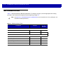
Revision History
Changes to the original guide are listed below:
Change
Date
Description
-01 Rev. A
6/2013
Initial Release.
-02 Rev. A
5/2014
Added:
- New software information
- Aux scanner parameters
- RS-232 NCR and Datalogic information
- Dual Cable Scale bar codes
- Reset button
- Third Party Scale parameters.
-03 Rev. A
7/2014
Added:
- New parameters...
- GS1 QR parameter
- GS1-Datamatrix parameter
- Center Object Detect
- Coerce UPC/EAN
- UPC/EAN/JAN Supplemental Aim ID Format
- Text to NCR Variant bullet under RS-232 Host Types
Updated:
- Renamed Bar Code Self Service Mode to Bar Code Hold-off Mode
- Changed the default for IBM Specification Version to Version 2.2
-04 Rev. A
11/2014
Zebra branding; add Symbol Native API (SNAPI) Interface bar code to USB chapter;
add SNAPI chapter.
iv
MP6000 BAR CODE PROGRAMMING GUIDE
TABLE OF CONTENTS
Warranty ......................................................................................................................................... ii
Revision History .............................................................................................................................. iii
About This Guide
Introduction .....................................................................................................................................
Chapter Descriptions ......................................................................................................................
Notational Conventions...................................................................................................................
Related Documents ........................................................................................................................
Recommended Services Information..............................................................................................
xiii
xiii
xiv
xv
xv
Chapter 1: USB INTERFACE BAR CODES
Introduction ....................................................................................................................................
USB Parameter Defaults ................................................................................................................
USB Host Parameters ....................................................................................................................
USB Device Type .....................................................................................................................
USB Country Keyboard Types - Country Codes ......................................................................
USB Keystroke Delay ..............................................................................................................
Simulated Caps Lock ...............................................................................................................
USB CAPS Lock Override .......................................................................................................
Scan Disable Mode ..................................................................................................................
USB Ignore Unknown Characters ............................................................................................
USB Convert Unknown to Code 39 .........................................................................................
USB Ignore Beep Directive ......................................................................................................
USB Ignore Type Directive ......................................................................................................
Emulate Keypad .......................................................................................................................
Emulate Keypad with Leading Zero .........................................................................................
USB Keyboard FN1 Substitution ..............................................................................................
Function Key Mapping .............................................................................................................
Convert Case ...........................................................................................................................
USB Static CDC .......................................................................................................................
USB Transmission Speed Parameters ....................................................................................
IBM USB Scale Default Response Status ...............................................................................
IBM Specification Version ........................................................................................................
ASCII Character Set for USB .........................................................................................................
1-1
1-2
1-3
1-3
1-9
1-14
1-17
1-19
1-21
1-24
1-26
1-28
1-30
1-32
1-34
1-36
1-38
1-40
1-43
1-45
1-58
1-61
1-63
vi
MP6000 BAR CODE PROGRAMMING GUIDE
Chapter 2: RS-232 INTERFACE BAR CODES
Introduction ....................................................................................................................................
RS-232 Parameter Defaults ...........................................................................................................
RS-232 Host Parameters ...............................................................................................................
RS-232 Host Types .......................................................................................................................
RS-232 Host -Datalogic Variant ...............................................................................................
RS-232 Host Preferences ..............................................................................................................
Baud Rate ................................................................................................................................
Parity ........................................................................................................................................
Stop Bits ...................................................................................................................................
Data Bits ..................................................................................................................................
Check Receive Errors ..............................................................................................................
Hardware Handshaking ...........................................................................................................
Software Handshaking .............................................................................................................
Host Serial Response Timeout ................................................................................................
RTS Line State .........................................................................................................................
Beep on <BEL> ........................................................................................................................
Intercharacter Delay .................................................................................................................
Wincor-Nixdorf Beep/LED Options ..........................................................................................
Ignore Unknown Characters ....................................................................................................
NCR Variant Preferences ........................................................................................................
ASCII Character Set for RS-232 ....................................................................................................
2-1
2-2
2-3
2-7
2-17
2-18
2-18
2-23
2-26
2-28
2-30
2-32
2-38
2-44
2-49
2-51
2-53
2-58
2-61
2-63
2-72
Chapter 3: IBM RS-485 INTERFACE BAR CODES
Introduction ....................................................................................................................................
IBM Parameter Defaults ................................................................................................................
IBM RS-485 Host Parameters .......................................................................................................
Port Address ............................................................................................................................
Scale Port Address ........................................................................................................................
IBM RS-485 Miscellaneous Parameters ........................................................................................
Convert Unknown to Code 39 ..................................................................................................
Ignore Beep Directive ..............................................................................................................
Ignore Configuration Directive .................................................................................................
Scan Disable Mode ..................................................................................................................
3-1
3-2
3-3
3-3
3-7
3-11
3-11
3-13
3-15
3-17
Chapter 4: SCALE CONFIGURATION
Introduction ....................................................................................................................................
Scanning Sequence Examples ......................................................................................................
Errors While Scanning ...................................................................................................................
Scale Parameter Defaults ..............................................................................................................
Legal Scale Units ...........................................................................................................................
Legal Scale Dampening Filter Setting ...........................................................................................
Scale Enable ..................................................................................................................................
Scale Reset ...................................................................................................................................
Scale Display Configuration ...........................................................................................................
Scale Enforce Zero Return ............................................................................................................
Scale Beep After Weight Request .................................................................................................
Ignore Scale Pole Directives ..........................................................................................................
Maximum Initial Zero Setting Range ..............................................................................................
4-1
4-2
4-2
4-2
4-3
4-5
4-9
4-11
4-12
4-14
4-16
4-18
4-20
TABLE OF CONTENTS
Chapter 5: USER PREFERENCES & MISCELLANEOUS OPTIONS
Introduction ....................................................................................................................................
Scanning Sequence Examples ......................................................................................................
Errors While Scanning ...................................................................................................................
User Preferences/Miscellaneous Options Parameter Defaults ......................................................
User Preferences ...........................................................................................................................
Set Default Parameter .............................................................................................................
Parameter Bar Code Scanning ................................................................................................
Beep After Good Decode .........................................................................................................
Beeper Tone ............................................................................................................................
Beeper Volume ........................................................................................................................
Beeper Duration .......................................................................................................................
Volume Button Enable .............................................................................................................
Suppress Power-up Beeps ......................................................................................................
Decode Session Timeout .........................................................................................................
Timeout Between Decodes, Same Symbol .............................................................................
Same Symbol Report Timeout .................................................................................................
Swipe Frame Timeout ..............................................................................................................
Presentation Frame Timeout ...................................................................................................
Cell Phone Frame Timeout ......................................................................................................
Fuzzy 1D Processing ...............................................................................................................
Mobile Phone Display Mode ....................................................................................................
PDF Prioritization .....................................................................................................................
PDF Prioritization Timeout .......................................................................................................
Center Object Detect ...............................................................................................................
Center IR Sensitivity ................................................................................................................
Stitching Type ..........................................................................................................................
Scanning Usage Mode .............................................................................................................
RS-232 Device Port Configuration ...........................................................................................
Third Party Scale Parameters ..................................................................................................
Exclude Decode Field Of Views ...............................................................................................
Illumination Configurations .......................................................................................................
Product ID (PID) Type ..............................................................................................................
Continuous Bar Code Read .....................................................................................................
Miscellaneous Scanner Parameters ..............................................................................................
Transmit Code ID Character ....................................................................................................
Prefix/Suffix Values ..................................................................................................................
Scan Data Transmission Format .............................................................................................
FN1 Substitution Values ..........................................................................................................
Copy Statistics to a Staging Flash Drive ..................................................................................
5-1
5-2
5-2
5-2
5-4
5-4
5-7
5-9
5-11
5-17
5-22
5-25
5-27
5-29
5-30
5-31
5-33
5-34
5-35
5-36
5-38
5-40
5-42
5-43
5-45
5-48
5-50
5-52
5-57
5-63
5-67
5-74
5-77
5-79
5-79
5-82
5-86
5-94
5-95
Chapter 6: EAS PARAMETERS
Introduction ....................................................................................................................................
Scanning Sequence Examples ......................................................................................................
Errors While Scanning ...................................................................................................................
User Preferences/Miscellaneous Options Parameter Defaults ......................................................
EAS Operating Modes ...................................................................................................................
Operating Modes ...........................................................................................................................
Sensormatic Auto Mode ...........................................................................................................
Sensormatic Always Enable Deactivation Mode ......................................................................
Sensormatic Bar Code Interlock Mode ....................................................................................
6-1
6-2
6-2
6-2
6-4
6-5
6-5
6-6
6-7
vii
viii
MP6000 BAR CODE PROGRAMMING GUIDE
Bar Code Auto Interlock Mode .................................................................................................
Bar Code Hold Off Mode ..........................................................................................................
Sensormatic Scan Enable Interlock Mode ...............................................................................
Checkpoint Bar Code Interlock Mode ......................................................................................
Checkpoint Scan Enable Interlock Mode .................................................................................
EAS LED On Mode ..................................................................................................................
EAS Disable Mode ...................................................................................................................
Sensormatic Deactivation Timeout ..........................................................................................
Sensormatic EAS Deactivation ................................................................................................
Sensormatic EAS Beeps ..........................................................................................................
Sensormatic Request Messages .............................................................................................
Checkpoint Interlock Polarity .........................................................................................................
Checkpoint Interlock Polarity (continued) ................................................................................
Deactivation Override Button .........................................................................................................
6-8
6-9
6-10
6-11
6-12
6-13
6-14
6-15
6-16
6-18
6-29
6-36
6-37
6-38
Chapter 7: AUXILIARY SCANNER BAR CODES
Introduction ....................................................................................................................................
Auxiliary Scanner Parameters .......................................................................................................
Auxiliary Scanner Decode with Unknown Type .......................................................................
Host Type .................................................................................................................................
Baud Rate ................................................................................................................................
Data Bits ..................................................................................................................................
Stop Bits ...................................................................................................................................
Parity ........................................................................................................................................
Host RTS State ........................................................................................................................
7-1
7-2
7-2
7-6
7-9
7-16
7-18
7-20
7-23
Chapter 8: 123SCAN2
Introduction .................................................................................................................................... 8-1
Chapter 9: SSI INTERFACE
Introduction .................................................................................................................................... 9-1
Chapter 10: SNAPI INTERFACE
Introduction .................................................................................................................................... 10-1
Chapter 11: SYMBOLOGIES
Introduction ....................................................................................................................................
Scanning Sequence Examples ......................................................................................................
Errors While Scanning ...................................................................................................................
Symbology Parameter Defaults .....................................................................................................
Disable All Code Types .................................................................................................................
UPC/EAN .......................................................................................................................................
Enable/Disable UPC-A .............................................................................................................
Enable/Disable UPC-E .............................................................................................................
Enable/Disable UPC-E1 ...........................................................................................................
Enable/Disable EAN-8/JAN-8 ..................................................................................................
Enable/Disable EAN-13/JAN-13 ..............................................................................................
Enable/Disable Bookland EAN ................................................................................................
Bookland ISBN Format ............................................................................................................
11-1
11-1
11-1
11-2
11-7
11-8
11-8
11-10
11-12
11-14
11-16
11-18
11-20
TABLE OF CONTENTS
Decode UPC/EAN/JAN Supplementals ...................................................................................
User-Programmable Supplementals ........................................................................................
UPC/EAN Redundancy ............................................................................................................
UPC/EAN/JAN Supplemental Redundancy .............................................................................
Transmit UPC-A Check Digit ...................................................................................................
Transmit UPC-E Check Digit ...................................................................................................
Transmit UPC-E1 Check Digit .................................................................................................
UPC-A Preamble .....................................................................................................................
UPC-E Preamble .....................................................................................................................
UPC-E1 Preamble ...................................................................................................................
Convert UPC-E to UPC-A ........................................................................................................
Convert UPC-E1 to UPC-A ......................................................................................................
EAN-8/JAN-8 Extend ...............................................................................................................
Coerce UPC/EAN ....................................................................................................................
UPC/EAN/JAN Supplemental AIM ID Format ..........................................................................
UCC Coupon Extended Code ..................................................................................................
Coupon Report .........................................................................................................................
ISSN EAN ................................................................................................................................
Code 128 .......................................................................................................................................
Enable/Disable Code 128 ........................................................................................................
Set Lengths for Code 128 ........................................................................................................
Enable/Disable GS1-128 (formerly UCC/EAN-128) .................................................................
Enable/Disable GS1-128 (formerly UCC/EAN-128) .................................................................
Enable/Disable ISBT 128 .........................................................................................................
ISBT Concatenation .................................................................................................................
Check ISBT Table ....................................................................................................................
ISBT Concatenation Redundancy ............................................................................................
Code 128 Stitching ...................................................................................................................
Code 128 Stitching Security Level ...........................................................................................
Code 128 Marginless Mode .....................................................................................................
Enable/Disable Code 39 ..........................................................................................................
Enable/Disable Trioptic Code 39 .............................................................................................
Convert Code 39 to Code 32 ...................................................................................................
Code 32 Prefix .........................................................................................................................
Set Lengths for Code 39 ..........................................................................................................
Code 39 Check Digit Verification .............................................................................................
Transmit Code 39 Check Digit .................................................................................................
Code 39 Full ASCII Conversion ...............................................................................................
Code 39 Stitching .....................................................................................................................
Code 39 Stitching Security Level .............................................................................................
Code 39 Marginless Mode .......................................................................................................
Code 93 .........................................................................................................................................
Enable/Disable Code 93 ..........................................................................................................
Set Lengths for Code 93 ..........................................................................................................
Code 93 Stitching .....................................................................................................................
Code 93 Stitching Security Level .............................................................................................
Code 93 Marginless Mode .......................................................................................................
Interleaved 2 of 5 (ITF) ..................................................................................................................
Enable/Disable Interleaved 2 of 5 ............................................................................................
I 2 of 5 Check Digit Verification ................................................................................................
Transmit I 2 of 5 Check Digit ....................................................................................................
ix
11-22
11-36
11-38
11-39
11-40
11-42
11-44
11-46
11-49
11-52
11-55
11-57
11-59
11-61
11-63
11-66
11-68
11-71
11-73
11-73
11-75
11-80
11-81
11-82
11-84
11-87
11-89
11-90
11-92
11-97
11-99
11-101
11-103
11-105
11-107
11-111
11-113
11-115
11-117
11-119
11-124
11-126
11-126
11-128
11-133
11-135
11-140
11-142
11-142
11-149
11-152
x
MP6000 BAR CODE PROGRAMMING GUIDE
Convert I 2 of 5 to EAN-13 .......................................................................................................
Interleaved 2 of 5 Stitching ......................................................................................................
Interleaved 2 of 5 Stitching Security Level ...............................................................................
Interleaved 2 of 5 Marginless Mode .........................................................................................
Discrete 2 of 5 (DTF/D 2 of 5) ........................................................................................................
Enable/Disable Discrete 2 of 5 .................................................................................................
Set Lengths for Discrete 2 of 5 ................................................................................................
Codabar (NW - 7) ..........................................................................................................................
Enable/Disable Codabar ..........................................................................................................
Set Lengths for Codabar ..........................................................................................................
CLSI Editing .............................................................................................................................
NOTIS Editing ..........................................................................................................................
Codabar Upper or Lower Case Start/Stop Characters Detection ............................................
MSI ................................................................................................................................................
Enable/Disable MSI .................................................................................................................
Set Lengths for MSI .................................................................................................................
MSI Check Digits .....................................................................................................................
Transmit MSI Check Digit(s) ....................................................................................................
MSI Check Digit Algorithm .......................................................................................................
Chinese 2 of 5 ................................................................................................................................
Enable/Disable Chinese 2 of 5 .................................................................................................
Inverse 1D .....................................................................................................................................
GS1 DataBar .................................................................................................................................
GS1 DataBar Limited ...............................................................................................................
GS1 DataBar Expanded ..........................................................................................................
GS1 DataBar Limited Security Level .......................................................................................
Convert GS1 DataBar to UPC/EAN .........................................................................................
Composite ......................................................................................................................................
Composite CC-C ......................................................................................................................
Composite CC-A/B ...................................................................................................................
Composite TLC-39 ...................................................................................................................
UPC Composite Mode .............................................................................................................
Composite Beep Mode ............................................................................................................
GS1-128 Emulation Mode for UCC/EAN Composite Codes ....................................................
2D Symbologies .............................................................................................................................
Enable/Disable PDF417 ...........................................................................................................
Enable/Disable MicroPDF417 ..................................................................................................
Code 128 Emulation ................................................................................................................
Data Matrix ...............................................................................................................................
Data Matrix Inverse ..................................................................................................................
GS1 Data Matrix ......................................................................................................................
QR Code ..................................................................................................................................
QR Inverse ...............................................................................................................................
GS1 QR ...................................................................................................................................
MicroQR ...................................................................................................................................
Aztec ........................................................................................................................................
Aztec Inverse ...........................................................................................................................
Redundancy Level .........................................................................................................................
Redundancy Level 1 ................................................................................................................
Redundancy Level 2 ................................................................................................................
Redundancy Level 3 ................................................................................................................
11-154
11-156
11-158
11-163
11-165
11-165
11-167
11-172
11-172
11-174
11-179
11-181
11-183
11-185
11-185
11-187
11-192
11-194
11-196
11-198
11-198
11-200
11-203
11-205
11-207
11-209
11-213
11-215
11-215
11-217
11-219
11-221
11-224
11-227
11-229
11-229
11-231
11-233
11-235
11-237
11-240
11-242
11-244
11-247
11-249
11-251
11-253
11-256
11-256
11-256
11-256
TABLE OF CONTENTS
xi
Redundancy Level 4 ................................................................................................................
Security Level ................................................................................................................................
Intercharacter Gap Size ...........................................................................................................
Macro PDF Features ......................................................................................................................
Flush Macro Buffer ...................................................................................................................
Abort Macro PDF Entry ............................................................................................................
11-256
11-261
11-265
11-267
11-267
11-268
Chapter 12: DRIVER’S LICENSE SET UP
Introduction ....................................................................................................................................
Driver’s License Parsing ................................................................................................................
No Driver’s License Parsing .....................................................................................................
Embedded Driver’s License Parsing ........................................................................................
Parsing Driver’s License Data Fields (Embedded Driver's License Parsing) .................................
Embedded Driver's License Parsing Criteria - Code Type .......................................................
Driver’s License Parse Field Bar Codes ..................................................................................
AAMVA Parse Field Bar Codes ...............................................................................................
Parser Version ID Bar Codes ...................................................................................................
User Preferences ...........................................................................................................................
Set Default Parameter .............................................................................................................
Output Gender as M or F .........................................................................................................
Date Format .............................................................................................................................
Send Keystroke (Control Characters and Keyboard Characters) ............................................
Parsing Rule Example ...................................................................................................................
Embedded Driver's License Parsing ADF Example .................................................................
12-1
12-5
12-5
12-6
12-7
12-7
12-8
12-21
12-90
12-91
12-91
12-92
12-93
12-106
12-234
12-255
Chapter 13: ADVANCED DATA FORMATTING
Introduction .................................................................................................................................... 13-1
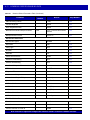
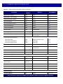
Appendix A: STANDARD DEFAULT PARAMETERS
Appendix B: PROGRAMMING REFERENCE
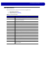
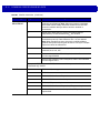
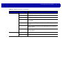
Symbol Code Identifiers ................................................................................................................. B-1
AIM Code Identifiers ...................................................................................................................... B-3
Appendix C: SAMPLE BAR CODES
Code 39 .........................................................................................................................................
UPC/EAN .......................................................................................................................................
UPC-A, 100% ...........................................................................................................................
EAN-13, 100% .........................................................................................................................
Code 128 .......................................................................................................................................
Interleaved 2 of 5 ...........................................................................................................................
GS1 DataBar-14 ............................................................................................................................
PDF417 ..........................................................................................................................................
Data Matrix .....................................................................................................................................
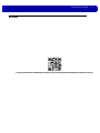
QR Code ........................................................................................................................................
C-1
C-2
C-2
C-3
C-4
C-5
C-6
C-7
C-8
C-9
xii
MP6000 BAR CODE PROGRAMMING GUIDE
Appendix D: NUMERIC BAR CODES
Numeric Bar Codes .......................................................................................................................
0 ...............................................................................................................................................
1 ...............................................................................................................................................
2 ...............................................................................................................................................
3 ...............................................................................................................................................
4 ...............................................................................................................................................
5 ...............................................................................................................................................
6 ...............................................................................................................................................
7 ...............................................................................................................................................
8 ...............................................................................................................................................
9 ...............................................................................................................................................
Cancel ............................................................................................................................................
D-1
D-1
D-2
D-3
D-4
D-5
D-6
D-7
D-8
D-9
D-10
D-11
Appendix E: ASCII CHARACTER SETS
Character Sets ............................................................................................................................... E-1
Index
ABOUT THIS GUIDE
Introduction
The MP6000 Bar Code Programming Guide includes the programming bar codes to configure the MP6000.
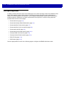
Chapter Descriptions
• Chapter 1, USB INTERFACE BAR CODES provides bar codes to set up the bioptic scanner with a USB host.
• Chapter 2, RS-232 INTERFACE BAR CODES provides bar codes to set up the bioptic scanner with an
RS-232 host, such as point-of-sale devices, host computers, or other devices with an available RS-232 port.
• Chapter 3, IBM RS-485 INTERFACE BAR CODES provides bar codes to set up the bioptic scanner with IBM
RS-485 Point of Sale (POS) systems.
• Chapter 4, SCALE CONFIGURATION provides bar codes to configure and calibrate the scale.
• Chapter 5, USER PREFERENCES & MISCELLANEOUS OPTIONS describes features frequently used to
customize how data transmits to the host device and programming bar codes for selecting user preference
features for the MP6000.
• Chapter 6, EAS PARAMETERS describes the EAS features, and provides programming bar codes for
selecting these features.
• Chapter 7, AUXILIARY SCANNER BAR CODES includes the parameter bar codes in this chapter configure
the MP6000 for connection to an auxiliary scanner.
• Chapter 8, 123SCAN2 describes the 123Scan2 utility.
• Chapter 9, SSI INTERFACE Customers using RS-232 OPOS require the Simple Serial Interface (SSI), which
provides a communications link between Zebra scanners, and a serial host.
• Chapter 10, SNAPI INTERFACE includes information about the USB-SNAPI Interface.
• Chapter 11, SYMBOLOGIES describes all symbology features and provides programming bar codes for
selecting these features for the MP6000.
• Chapter 12, DRIVER’S LICENSE SET UP describes how to program the MP6000 to read and use the data
contained in the 2D bar codes on US driver's licenses, and AAMVA compliant ID cards.
• Chapter 13, ADVANCED DATA FORMATTING briefly describes ADF and refers to the guide.
xiv
MP6000 BAR CODE PROGRAMMING GUIDE
• Appendix A, STANDARD DEFAULT PARAMETERS provides a table of all host devices and
miscellaneous scanner defaults.
• Appendix B, PROGRAMMING REFERENCE provides a table of AIM code identifiers, ASCII character
conversions, and keyboard maps.
• Appendix C, SAMPLE BAR CODES includes sample bar codes of various code types.
• Appendix D, NUMERIC BAR CODES includes the numeric bar codes to scan for parameters requiring
specific numeric values.
• Appendix E, ASCII CHARACTER SETS includes ASCII character set values.
Notational Conventions
The following conventions are used in this document:
• Italics are used to highlight the following:
• Chapters and sections in this and related documents
• Dialog box, window and screen names
• Drop-down list and list box names
• Check box and radio button names.
• Bold text is used to highlight the following:
• Key names on a keypad
• Button names on a screen.
• bullets (•) indicate:
• Action items
• Lists of alternatives
• Lists of required steps that are not necessarily sequential
• Sequential lists (e.g., those that describe step-by-step procedures) appear as numbered lists.
• Throughout the programming bar code menus, asterisks (*) are used to denote default parameter
settings.
* Indicates Default
*Baud Rate 9600
Feature/Option
• Symbols:
NOTE
This symbol indicates something of special interest or importance to the reader. Failure to read the
note will not result in physical harm to the reader, equipment or data.
CAUTION
This symbol indicates that if this information is ignored, the possibility of data or material damage
may occur.
IMPORTANT This symbol points out meaningful advice.
WARNING!
This symbol indicates that if this information is ignored the possibility that serious
personal injury may occur.
ABOUT THIS GUIDE
xv
Related Documents
• MP6000 Integrator Guide, p/n 72E-172632-xx, provides installation information, interface setups, scale
calibration procedure, beeper and LED indicators, warning and error messages, and information about
using the MP6000.
• Advanced Data Formatting Programmer Guide (ADF), p/n 72E-69680-xx, provides ADF information and
the bar codes necessary to customize data before transmission to a host.
For the latest version of this guide and all guides, go to: http://www.motorolasolutions.com/support.
Recommended Services Information
If you have a problem using the equipment, contact your facility's technical or systems support. If there is a
problem with the equipment, they will contact the Zebra Customer Support Center at:
http://www.motorolasolutions.com/support.
When contacting Zebra support, please have the following information available:
• Serial number of the unit
• Model number or product name
• Software type and version number
responds to calls by e-mail, telephone or fax within the time limits set forth in service agreements.
If your problem cannot be solved by the Zebra Customer Support Center, you may need to return your
equipment for servicing and will be given specific directions or a Field Service Technician may be sent to your
location to perform the repair, depending on your level of entitlement set forth in the service agreement. is not
responsible for any damages incurred during shipment if the approved shipping container is not used. Shipping
the units improperly can possibly void the warranty.
If you purchased your business product from a business partner, please contact that business partner for
support.
recommends the following Service options to keep the MP6000 operating at peak performance throughout its
lifecycle:
• Service from the Start with Advance Exchange Support (available for scanner-only configurations).
• Service from the Start with On Site System Support (available for scanner-only and scanner/scale
configurations).
xvi
MP6000 BAR CODE PROGRAMMING GUIDE
CHAPTER 1 USB INTERFACE BAR CODES
Introduction
This chapter includes the programming bar codes for the USB host interface. The MP6000 connects directly to
a USB host, or a powered USB hub. An additional power supply is required (PWRS-14000-148R). Only a USB
Power Plus host (IBM registers) can power the MP6000 using a Power Plus cable, with an external power
supply.
For detailed technical information about the MP6000 including installation, setting up interfaces, calibrating the
scale, and operation refer to the MP6000 Integrator Guide (p/n 72E-172632-xx).
Throughout the programming bar code menus, asterisks (*) indicate default values.
*Indicates Default
*Scan Disable Mode - Full Disable
Feature/Option
1-2
MP6000 BAR CODE PROGRAMMING GUIDE
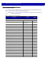
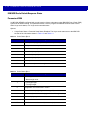
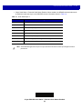
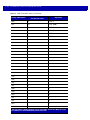
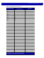
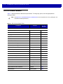
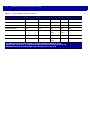
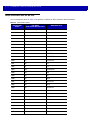
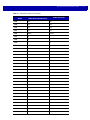
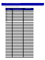
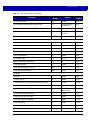
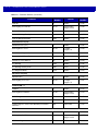
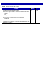
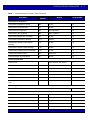
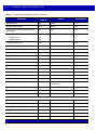
USB Parameter Defaults
Table 1-1 lists the defaults for USB host parameters. To change any option, scan the appropriate bar code(s)
provided in the Parameter Descriptions section beginning on page 1-3.
NOTE
See Appendix A, STANDARD DEFAULT PARAMETERS for all user preferences, hosts, symbologies, and
miscellaneous default parameters.
Table 1-1 USB Interface Parameter Defaults
Parameter
Default
Page
Number
USB Host Parameters
USB Device Type
IBM Table Top
1-3
USB Country Keyboard Types - Country Codes
North American Standard
USB Keyboard
1-9
USB Keystroke Delay
No Delay
1-14
Simulated Caps Lock
Disable
1-17
USB CAPS Lock Override
Disable
1-19
Scan Disable Mode
Full Disable
1-21
USB Ignore Unknown Characters
Enable
1-19
Scan Disable Mode
Full Disable
1-21
USB Ignore Unknown Characters
Enable
1-24
USB Convert Unknown to Code 39
Disable
1-26
USB Ignore Beep Directive
Ignore
1-28
USB Ignore Type Directive
Ignore
1-30
Emulate Keypad
Disable
1-32
Emulate Keypad with Leading Zero
Disable
1-34
USB Keyboard FN 1 Substitution
Disable
1-36
Function Key Mapping
Disable
1-38
Convert Case
Disable
1-40
USB Static CDC
Enable
1-43
USB HID Polling Interval
8 msec
1-45
Fast HID Keyboard
Disable
1-54
Quick Keypad Emulation
Disable
1-56
IBM USB Scale Default Response Status
Disabled
1-58
IBM Specification Version
Version 2.2
1-61
USB INTERFACE BAR CODES
1-3
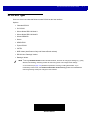
USB Host Parameters
USB Device Type
Select the desired USB device type from the following options.
• * IBM Table-top USB
• IBM Hand-held USB
• IBM OPOS (IBM Hand-held USB with Full Scan Disable)
• HID Keyboard Emulation
• CDC COM Port Emulation.
• Symbol Native API (SNAPI)
NOTE
1. When changing USB device types, the MP6000 automatically resets and issues the standard
startup beep sequences.
2. Select IBM Hand-held USB to disable data transmission when an IBM register issues a Scan
Disable command. Illumination and decoding are still permitted. Select IBM OPOS (IBM Hand-held
USB with Full Scan Disable) to completely shut off the scanner when an IBM register issues a Scan
Disable command, including illumination, decoding, and data transmission.
3. Before selecting CDC COM Port Emulation, install the USB CDC driver on the host to ensure the
scanner does not stall during power up (due to a failure to enumerate USB). If the scanner stalls, to
recover it:
a. Install the USB CDC driver
or
b. After power-up, hold the trigger for 10 seconds, which allows the scanner to power up using an
alternate USB configuration. Upon power-up, scan another USB Device Type.
* IBM Table-top USB
1-4
MP6000 BAR CODE PROGRAMMING GUIDE
USB Device Type (continued)
IBM Hand-held USB
USB INTERFACE BAR CODES
USB Device Type (continued)
IBM OPOS
(IBM Hand-held USB with Full Scan Disable)
1-5
1-6
MP6000 BAR CODE PROGRAMMING GUIDE
USB Device Type (continued)
When the HID Keyboard host is selected, and the MP6000 has auxiliary scanners connected, use ADF rules to
program the auxiliary scanners to add a 500 msec pause to the end of the data to prevent the interleaving of bar
code data from multiple scanners. This works with standard RS-232, and SSI over RS-232 (with the Send Raw
Decode Data setting).
HID Keyboard Emulation
USB INTERFACE BAR CODES
USB Device Type (continued)
CDC COM Port Emulation
1-7
1-8
MP6000 BAR CODE PROGRAMMING GUIDE
USB Device Type (continued)
Symbol Native API (SNAPI) Interface
USB INTERFACE BAR CODES
1-9
USB Country Keyboard Types - Country Codes
Scan the bar code corresponding to the keyboard type from the following options. This setting applies only to
the USB HID Keyboard Emulation device.
Options:
• *North American Standard USB Keyboard
• German Windows
• French Windows
• French Canadian Windows 95/98
• French Canadian Windows 2000/XP.
NOTE
When changing USB country keyboard types the digital scanner automatically resets and issues the
standard startup beep sequences.
*North American Standard USB Keyboard
1 - 10 MP6000 BAR CODE PROGRAMMING GUIDE
USB Country Keyboard Types - Country Codes (continued)
German Windows
USB INTERFACE BAR CODES 1 - 11
USB Country Keyboard Types - Country Codes (continued)
French Windows
1 - 12 MP6000 BAR CODE PROGRAMMING GUIDE
USB Country Keyboard Types - Country Codes (continued)
French Canadian Windows 95/98
USB INTERFACE BAR CODES 1 - 13
USB Country Keyboard Types - Country Codes (continued)
French Canadian Windows 2000/XP
1 - 14 MP6000 BAR CODE PROGRAMMING GUIDE
USB Keystroke Delay
This parameter sets the delay, in milliseconds, between emulated keystrokes. Scan the appropriate bar code
from the following options to increase the delay when hosts require a slower transmission of data.
Options:
• *No Delay
• Medium Delay (20 msec)
• Long Delay (40 msec).
*No Delay
USB INTERFACE BAR CODES 1 - 15
USB Keystroke Delay (continued)
Medium Delay (20 msec)
1 - 16 MP6000 BAR CODE PROGRAMMING GUIDE
USB Keystroke Delay (continued)
Long Delay (40 msec)
USB INTERFACE BAR CODES 1 - 17
Simulated Caps Lock
Enable this to invert upper and lower case characters on the bar code as if the Caps Lock state is enabled on
the keyboard. This inversion occurs regardless of the keyboard’s Caps Lock state. Note that this only applies
to alpha characters.
Options:
• *Disable Simulated Caps Lock
• Enable Simulated Caps Lock.
*Disable Simulated Caps Lock
1 - 18 MP6000 BAR CODE PROGRAMMING GUIDE
Simulated Caps Lock (continued)
Enable Simulated Caps Lock
USB INTERFACE BAR CODES 1 - 19
USB CAPS Lock Override
This option applies only to the HID Keyboard Emulation device. Enable this to preserve the case of the data
regardless of the state of the Caps Lock key. This setting is always enabled for the Japanese, Windows
(ASCII) keyboard type and can not be disabled.
Options:
• *Do Not Override Caps Lock Key (Disable)
• Override Caps Lock Key (Enable).
NOTE
If both Simulated Caps Lock and Caps Lock Override are enabled, Caps Lock Override takes
precedence.
Override Caps Lock Key
(Enable)
1 - 20 MP6000 BAR CODE PROGRAMMING GUIDE
USB CAPS Lock Override (continued)
*Do Not Override Caps Lock Key
(Disable)
USB INTERFACE BAR CODES 1 - 21
Scan Disable Mode
Parameter # 1214
This parameter determines the behavior of the MP6000 when it receives a Scan Disable directive from the
connected host.
Options:
• *Full Disable - Scanning bar codes is disabled.
• Transmit Disable - The MP6000 may scan bar codes, but transmission of bar code data is disabled.
• Auto Disable - MP6000 disables scanning after transmission of a bar code, and remains disabled until
the host sends a Scan Enable.
NOTE
This feature is currently supported by IBM Table Top USB, IBM Hand-held USB, and all IBM 46XX
interfaces.
* Full Disable
(0)
1 - 22 MP6000 BAR CODE PROGRAMMING GUIDE
Scan Disable Mode (continued)
Transmit Disable
(1)
USB INTERFACE BAR CODES 1 - 23
Scan Disable Mode (continued)
Auto Disable
(2)
1 - 24 MP6000 BAR CODE PROGRAMMING GUIDE
USB Ignore Unknown Characters
This option applies only to the IBM device. Unknown characters are characters the host does not recognize.
Options:
• *Send Bar Codes with Unknown Characters - Select Send Bar Codes With Unknown Characters to
send all bar code data except for unknown characters. The MP6000 issues no error beeps.
• Do Not Send Bar Codes with Unknown Characters - Select Do Not Send Bar Codes With Unknown
Characters, for IBM devices, to prevent sending bar codes containing at least one unknown character to
the host. The MP6000 issues an error beep.
*Send Bar Codes with Unknown Characters
USB INTERFACE BAR CODES 1 - 25
USB Ignore Unknown Characters (continued)
Do Not Send Bar Codes with Unknown Characters
1 - 26 MP6000 BAR CODE PROGRAMMING GUIDE
USB Convert Unknown to Code 39
This option applies only to the IBM Hand-held, IBM Table Top, and IBM OPOS (IBM Hand-held USB with Full
Scan Disable) devices. Scan a bar code below to enable or disable converting unknown bar code type data to
Code 39.
Options:
• *Disable Convert Unknown to Code 39
• Enable Convert Unknown to Code 39.
*Disable Convert Unknown to Code 39
USB INTERFACE BAR CODES 1 - 27
USB Convert Unknown to Code 39 (continued)
Enable Convert Unknown to Code 39
1 - 28 MP6000 BAR CODE PROGRAMMING GUIDE
USB Ignore Beep Directive
This applies only to IBM Hand-held, IBM Table Top, and IBM OPOS (IBM Hand-held USB with Full Scan
Disable) devices. Scan one of the following bar codes to honor or ignore a beep directive. All directives are still
acknowledged as if they were processed.
Options:
• Honor USB Beep Directive
• *Ignore USB Beep Directive.
Honor USB Beep Directive
USB INTERFACE BAR CODES 1 - 29
USB Ignore Beep Directive (continued)
*Ignore USB Beep Directive
1 - 30 MP6000 BAR CODE PROGRAMMING GUIDE
USB Ignore Type Directive
This applies only to IBM hand-held, IBM tabletop, and OPOS devices. Scan one of the following bar codes to
honor or ignore a code type enable/disable directive. All directives are still acknowledged as if they were
processed.
Options:
• Honor USB Ignore Type Directive
• *Ignore USB Type Directive.
Honor USB Ignore Type Directive
USB INTERFACE BAR CODES 1 - 31
USB Ignore Type Directive (continued)
*Ignore USB Type Directive
1 - 32 MP6000 BAR CODE PROGRAMMING GUIDE
Emulate Keypad
Enable this to send all characters as ASCII sequences over the numeric keypad. For example ASCII A
transmits as “ALT make” 0 6 5 “ALT Break”.
Options:
• *Disable Keypad Emulation
• Enable Keypad Emulation.
*Disable Keypad Emulation
USB INTERFACE BAR CODES 1 - 33
Emulate Keypad (continued)
Enable Keypad Emulation
1 - 34 MP6000 BAR CODE PROGRAMMING GUIDE
Emulate Keypad with Leading Zero
Enable this to send character sequences sent over the numeric keypad as ISO characters which have a
leading zero. For example ASCII A transmits as “ALT MAKE” 0 0 6 5 “ALT BREAK”.
Options:
• *Disable Keypad Emulation with Leading Zero
• Enable Keypad Emulation with Leading Zero.
*Disable Keypad Emulation with Leading Zero
USB INTERFACE BAR CODES 1 - 35
Emulate Keypad with Leading Zero (continued)
Enable Keypad Emulation with Leading Zero
1 - 36 MP6000 BAR CODE PROGRAMMING GUIDE
USB Keyboard FN1 Substitution
This option applies only to the USB HID Keyboard Emulation device. Enable this to replace any FN1
characters in an EAN 128 bar code with a user-selected Key Category and value (see FN1 Substitution Values
on page 5-94 to set the Key Category and Key Value).
Options:
• Enable USB Keyboard FN1 Substitution
• *Disable USB Keyboard FN1 Substitution.
Enable USB Keyboard FN1 Substitution
USB INTERFACE BAR CODES 1 - 37
USB Keyboard FN 1 Substitution (continued)
*Disable USB Keyboard FN1 Substitution
1 - 38 MP6000 BAR CODE PROGRAMMING GUIDE
Function Key Mapping
ASCII values under 32 are normally sent as a control-key sequences (see Table 1-5 on page 1-63). Enable this
parameter to send the keys in bold in place of the standard key mapping. Table entries that do not have a bold
entry remain the same whether or not you enable this parameter.
Options:
• *Disable Function Key Mapping
• Enable Function Key Mapping.
*Disable Function Key Mapping
USB INTERFACE BAR CODES 1 - 39
Function Key Mapping (continued)
Enable Function Key Mapping
1 - 40 MP6000 BAR CODE PROGRAMMING GUIDE
Convert Case
Enable this to convert all bar code data to the selected case.
Options:
• *No Case Conversion
• Convert All to Upper Case
• Convert All to Lower Case.
*No Case Conversion
USB INTERFACE BAR CODES 1 - 41
Convert Case (continued)
Convert All to Upper Case
1 - 42 MP6000 BAR CODE PROGRAMMING GUIDE
Convert Case (continued)
Convert All to Lower Case
USB INTERFACE BAR CODES 1 - 43
USB Static CDC
When disabled, each device connected consumes another COM port (first device = COM1,
second device = COM2, third device = COM3, etc.)
When enabled, each device connects to the same COM port
Options:
• *Enable USB Static CDC
• Disable USB Static CDC.
*Enable USB Static CDC
1 - 44 MP6000 BAR CODE PROGRAMMING GUIDE
USB Static CDC (continued)
Disable USB Static CDC
USB INTERFACE BAR CODES 1 - 45
USB Transmission Speed Parameters
Use the following parameters to speed USB data transmission:
• USB HID Polling Interval - When using more current USB systems, use this parameter to set a lower
interval in order to increase data transmission speed.
• Fast HID Keyboard - When configured as a USB HID keyboard device, use this parameter to increase
the data transmission speed of printable (7-bit) ASCII characters.
• Quick Keypad Emulation - When configured as a USB HID keyboard device, use this parameter to
increase the data transmission speed of a mix of both printable (7-bit) and full (8-bit) ASCII characters.
NOTE
Enabling Emulate Keypad on page 1-32 or Quick Keypad Emulation on page 1-56 overrides Fast HID
Keyboard.
USB HID Polling Interval
This option speeds data transmission for all USB devices except CDC. Scan the appropriate bar code to set
the polling interval. The polling interval determines the rate at which data can be sent between the scanner and
the host computer. A lower number indicates a faster data rate. The default value is 8 msec.
Options:
•
•
•
•
•
•
•
•
1 msec
2 msec
3 msec
4 msec
5 msec
6 msec
7 msec
* 8 msec.
Changing the polling interval re-initializes the scanner.
CAUTION
Ensure the host can handle the selected data rate. Selecting a data rate that is too fast for the host can
result in lost data.
1 msec
1 - 46 MP6000 BAR CODE PROGRAMMING GUIDE
USB HID Polling Interval (continued)
2 msec
USB INTERFACE BAR CODES 1 - 47
USB HID Polling Interval (continued)
3 msec
1 - 48 MP6000 BAR CODE PROGRAMMING GUIDE
USB HID Polling Interval (continued)
4 msec
USB INTERFACE BAR CODES 1 - 49
USB HID Polling Interval (continued)
5 msec
1 - 50 MP6000 BAR CODE PROGRAMMING GUIDE
USB HID Polling Interval (continued)
6 msec
USB INTERFACE BAR CODES 1 - 51
USB HID Polling Interval (continued)
7 msec
1 - 52 MP6000 BAR CODE PROGRAMMING GUIDE
USB HID Polling Interval (continued)
*8 msec
USB INTERFACE BAR CODES 1 - 53
USB HID Polling Interval (continued)
9 msec
1 - 54 MP6000 BAR CODE PROGRAMMING GUIDE
Fast HID Keyboard
This option transmits USB HID keyboard data at a faster rate.
Options:
• Enable Fast HID Keyboard
• * Disable Fast HID Keyboard.
NOTE
Enabling Emulate Keypad on page 1-32 or Quick Keypad Emulation overrides Fast HID Keyboard.
Enable
USB INTERFACE BAR CODES 1 - 55
Fast HID Keyboard (continued)
*Disable
1 - 56 MP6000 BAR CODE PROGRAMMING GUIDE
Quick Keypad Emulation
This option applies only to the HID keyboard emulation device when Emulate Keypad on page 1-32 is enabled.
This parameter enables a quicker method of emulation utilizing the numeric keypad. The default value is
Disable.
Options:
• Enable Quick Keypad Emulation
• *Disable Quick Keypad Emulation.
NOTE
Enabling Emulate Keypad on page 1-32 or Quick Keypad Emulation overrides Fast HID Keyboard.
Enable
USB INTERFACE BAR CODES 1 - 57
Quick Keypad Emulation (continued)
*Disable
1 - 58 MP6000 BAR CODE PROGRAMMING GUIDE
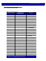
IBM USB Scale Default Response Status
Parameter #1286
An MP6200 (MP6000 configured with a scale) sends a 2-byte scale status to the IBM USB Point of Sale (POS)
system as the default setting. This parameter allows a user to program the MP6200 scanner/scale to send
either 2-byte scale status, or a 3-byte scale extended status.
Options:
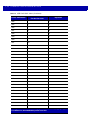
• *2-byte Scale Status - Extended Scale Status Disabled: The 2-byte scale status sent to the IBM POS
consists of the information shown in Table 1-2 and Table 1-3.
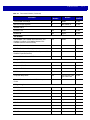
Table 1-2 Scale Status Byte 0
Bit Position
Description
0
Flash update in progress (if flash update is implemented).
1
Configuration data response frame.
2
Extended status response frame.
3
Not defined (always 0).
4
Not defined (always 0).
5
Not defined (always 0).
6
Unacceptable command.
7
Device not ready to receive weigh commands.
Table 1-3 Scale Status Byte 1
Bit Position
Description
0
0: US weigh mode.
1: Metric weigh mode.
1
0: Four digit weight.
1: Five digit weight.
2
Weight data not include/scale in motion.
3
Data value error (weight digits not in range 0-9).
4
Read error (timeout occurred trying to obtain valid weight/status).
5
Remote display required but not detected.
6
Scale hardware error.
7
Undefined command received (command reject).
USB INTERFACE BAR CODES 1 - 59
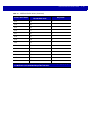
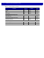
• 3-byte Scale Status - Extended Scale Status Enabled: When enabled, the MP6200 scanner/scale sends
an additional scale status byte to the IBM POS with the information shown in Table 1-4.
Table 1-4 Scale Status Byte 2
Bit Position
Description
0
Configuration successful.
1
Scale under zero.
2
Scale over capacity.
3
Scale center-of-zero.
4
Scale requires zeroing.
5
Scale warm up in progress.
6
Duplicate weight (United Kingdom mode only).
7
Not defined (always 0).
NOTE
Some IBM POS applications require a 3-byte extended scale status for better price/weight transaction
performance.
*2-byte IBM USB Scale Status - Extended Scale Status Disabled
(0)
1 - 60 MP6000 BAR CODE PROGRAMMING GUIDE
IBM USB Scale Default Response Status (continued)
3-byte IBM USB Scale Status - Extended Scale Status Enabled
(1)
USB INTERFACE BAR CODES 1 - 61
IBM Specification Version
The IBM USB interface specification version selected defines how code types are reported over the IBM USB
interface.
Options:
• Original Specification
• *Version 2.2.
Original Specification
1 - 62 MP6000 BAR CODE PROGRAMMING GUIDE
IBM Specification Version (continued)
*Version 2.2
USB INTERFACE BAR CODES 1 - 63
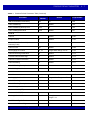
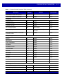
ASCII Character Set for USB
Table 1-5 USB Prefix/Suffix Values
Full ASCII Code 39
Encode Char.acter
Prefix/ Suffix Value
Keystroke
1000
%U
CTRL 2
1001
$A
CTRL A
1002
$B
CTRL B
1003
$C
CTRL C
1004
$D
CTRL D
1005
$E
CTRL E
1006
$F
CTRL F
1007
$G
CTRL G
1008
$H
CTRL H/BACKSPACE1
1009
$I
CTRL I/HORIZONTAL TAB1
1010
$J
CTRL J
1011
$K
CTRL K
1012
$L
CTRL L
1013
$M
CTRL M/ENTER1
1014
$N
CTRL N
1015
$O
CTRL O
1016
$P
CTRL P
1017
$Q
CTRL Q
1018
$R
CTRL R
1019
$S
CTRL S
1020
$T
CTRL T
1021
$U
CTRL U
1022
$V
CTRL V
1023
$W
CTRL W
1024
$X
CTRL X
1025
$Y
CTRL Y
1
The keystroke in bold transmits only if you enable Function Key Mapping on page
1-38. Otherwise, the unbolded keystroke transmits.
1 - 64 MP6000 BAR CODE PROGRAMMING GUIDE
Table 1-5 USB Prefix/Suffix Values (Continued)
Full ASCII Code 39
Encode Char.acter
Prefix/ Suffix Value
Keystroke
1026
$Z
CTRL Z
1027
%A
CTRL [/ESC1
1028
%B
CTRL \
1029
%C
CTRL ]
1030
%D
CTRL 6
1031
%E
CTRL -
1032
Space
Space
1033
/A
!
1034
/B
“
1035
/C
#
1036
/D
$
1037
/E
%
1038
/F
&
1039
/G
‘
1040
/H
(
1041
/I
)
1042
/J
*
1043
/K
+
1044
/L
,
1045
-
-
1046
.
.
1047
/O
/
1048
0
0
1049
1
1
1050
2
2
1051
3
3
1052
4
4
1053
5
5
1054
6
6
1
The keystroke in bold transmits only if you enable Function Key Mapping on page
1-38. Otherwise, the unbolded keystroke transmits.
USB INTERFACE BAR CODES 1 - 65
Table 1-5 USB Prefix/Suffix Values (Continued)
Full ASCII Code 39
Encode Char.acter
Prefix/ Suffix Value
Keystroke
1055
7
7
1056
8
8
1057
9
9
1058
/Z
:
1059
%F
;
1060
%G
<
1061
%H
=
1062
%I
>
1063
%J
?
1064
%V
@
1065
A
A
1066
B
B
1067
C
C
1068
D
D
1069
E
E
1070
F
F
1071
G
G
1072
H
H
1073
I
I
1074
J
J
1075
K
K
1076
L
L
1077
M
M
1078
N
N
1079
O
O
1080
P
P
1081
Q
Q
1082
R
R
1083
S
S
1
The keystroke in bold transmits only if you enable Function Key Mapping on page
1-38. Otherwise, the unbolded keystroke transmits.
1 - 66 MP6000 BAR CODE PROGRAMMING GUIDE
Table 1-5 USB Prefix/Suffix Values (Continued)
Full ASCII Code 39
Encode Char.acter
Prefix/ Suffix Value
Keystroke
1084
T
T
1085
U
U
1086
V
V
1087
W
W
1088
X
X
1089
Y
Y
1090
Z
Z
1091
%K
[
1092
%L
\
1093
%M
]
1094
%N
^
1095
%O
_
1096
%W
`
1097
+A
a
1098
+B
b
1099
+C
c
1100
+D
d
1101
+E
e
1102
+F
f
1103
+G
g
1104
+H
h
1105
+I
i
1106
+J
j
1107
+K
k
1108
+L
l
1109
+M
m
1110
+N
n
1111
+O
o
1112
+P
p
1
The keystroke in bold transmits only if you enable Function Key Mapping on page
1-38. Otherwise, the unbolded keystroke transmits.
USB INTERFACE BAR CODES 1 - 67
Table 1-5 USB Prefix/Suffix Values (Continued)
Full ASCII Code 39
Encode Char.acter
Prefix/ Suffix Value
Keystroke
1113
+Q
q
1114
+R
r
1115
+S
s
1116
+T
t
1117
+U
u
1118
+V
v
1119
+W
w
1120
+X
x
1121
+Y
y
1122
+Z
z
1123
%P
{
1124
%Q
|
1125
%R
}
1126
%S
~
1The
keystroke in bold transmits only if you enable Function Key Mapping on page
1-38. Otherwise, the unbolded keystroke transmits.
1 - 68 MP6000 BAR CODE PROGRAMMING GUIDE
Table 1-6 USB ALT Key Character Set
ALT Keys
Keystroke
2064
ALT 2
2065
ALT A
2066
ALT B
2067
ALT C
2068
ALT D
2069
ALT E
2070
ALT F
2071
ALT G
2072
ALT H
2073
ALT I
2074
ALT J
2075
ALT K
2076
ALT L
2077
ALT M
2078
ALT N
2079
ALT O
2080
ALT P
2081
ALT Q
2082
ALT R
2083
ALT S
2084
ALT T
2085
ALT U
2086
ALT V
2087
ALT W
2088
ALT X
2089
ALT Y
2090
ALT Z
USB INTERFACE BAR CODES 1 - 69
Table 1-7 USB GUI Key Character Set
GUI Key
Keystroke
3000
Right Control Key
3048
GUI 0
3049
GUI 1
3050
GUI 2
3051
GUI 3
3052
GUI 4
3053
GUI 5
3054
GUI 6
3055
GUI 7
3056
GUI 8
3057
GUI 9
3065
GUI A
3066
GUI B
3067
GUI C
3068
GUI D
3069
GUI E
3070
GUI F
3071
GUI G
3072
GUI H
3073
GUI I
3074
GUI J
3075
GUI K
3076
GUI L
3077
GUI M
3078
GUI N
3079
GUI O
3080
GUI P
3081
GUI Q
Note: GUI Shift Keys - The Apple™ iMac keyboard has
an apple key on either side of the space bar.
Windows-based systems have a GUI key to the left of
the left ALT key, and to the right of the right ALT key.
1 - 70 MP6000 BAR CODE PROGRAMMING GUIDE
Table 1-7 USB GUI Key Character Set (Continued)
GUI Key
Keystroke
3082
GUI R
3083
GUI S
3084
GUI T
3085
GUI U
3086
GUI V
3087
GUI W
3088
GUI X
3089
GUI Y
3090
GUI Z
Note: GUI Shift Keys - The Apple™ iMac keyboard has
an apple key on either side of the space bar.
Windows-based systems have a GUI key to the left of
the left ALT key, and to the right of the right ALT key.
USB INTERFACE BAR CODES 1 - 71
Table 1-8 USB F Key Character Set
F Keys
Keystroke
5001
F1
5002
F2
5003
F3
5004
F4
5005
F5
5006
F6
5007
F7
5008
F8
5009
F9
5010
F10
5011
F11
5012
F12
5013
F13
5014
F14
5015
F15
5016
F16
5017
F17
5018
F18
5019
F19
5020
F20
5021
F21
5022
F22
5023
F23
5024
F24
1 - 72 MP6000 BAR CODE PROGRAMMING GUIDE
Table 1-9 USB Numeric Keypad Character Set
Numeric Keypad
Keystroke
6042
*
6043
+
6044
undefined
6045
-
6046
.
6047
/
6048
0
6049
1
6050
2
6051
3
6052
4
6053
5
6054
6
6055
7
6056
8
6057
9
6058
Enter
6059
Num Lock
USB INTERFACE BAR CODES 1 - 73
Table 1-10 USB Extended Keypad Character Set
Extended Keypad
Keystroke
7001
Break
7002
Delete
7003
PgUp
7004
End
7005
Pg Dn
7006
Pause
7007
Scroll Lock
7008
Backspace
7009
Tab
7010
Print Screen
7011
Insert
7012
Home
7013
Enter
7014
Escape
7015
Up Arrow
7016
Down Arrow
7017
Left Arrow
7018
Right Arrow
1 - 74 MP6000 BAR CODE PROGRAMMING GUIDE
CHAPTER 2 RS-232 INTERFACE BAR CODES
Introduction
This chapter includes the programming bar codes for the RS-232 host interface. Use the RS-232 interface to
connect the MP6000 to POS devices, host computers, or other devices with an available RS-232 port (e.g.,
com port).
For detailed technical information about the MP6000 including installation, setting up interfaces, calibrating the
scale, and operation refer to the MP6000 Integrator Guide (p/n 72E-172632-xx). Also see Character Sets on
page E-1 for the character sets.
NOTE
The MP6000 uses TTL RS-232 signal levels, which interface with most system architectures. For system
architectures requiring RS-232C signal levels, offers different cables providing TTL-to-RS-232C
conversion.
Throughout the programming bar code menus, asterisks (*) indicate default values.
* Indicates Default
*Baud Rate 9,600
Feature/Option
2-2
MP6000 BAR CODE PROGRAMMING GUIDE
RS-232 Parameter Defaults
Table 2-1 lists the defaults for RS-232 host parameters. To change any option, scan the appropriate bar
code(s) provided.
NOTE
See Appendix A, STANDARD DEFAULT PARAMETERS for all user preferences, hosts, symbologies, and
miscellaneous default parameters.
Table 2-1 RS-232 Host Default Table
Parameter
Default
Page
Number
RS-232 Host Parameters
RS-232 Host Types
Standard
2-7
Baud Rate
9600
2-18
Parity Type
None
2-23
Stop Bits
1
2-26
Data Bits
8-bit
2-28
Check Receive Errors
Enable
2-30
Hardware Handshaking
None
2-32
Software Handshaking
None
2-38
Host Serial Response Timeout
2 Sec
2-44
RTS Line State
Low RTS
2-49
Beep on <BEL>
Disable
2-51
Intercharacter Delay
0 msec
2-53
Wincor-Nixdorf Beep/LED Options
Normal Operation
2-58
Ignore Unknown Characters
Send Bar Code
2-61
NCR Use Prefix
Enabled
2-63
NCR Prefix
1002 (STX)
2-65
NCR Suffix
1003 (ETX)
2-66
NCR Use Block Check Character
Enabled
2-67
NCR Interface
Follow System
2-69
RS-232 INTERFACE BAR CODES
2-3
RS-232 Host Parameters
Various RS-232 hosts use their own parameter default settings. Selecting standard, ICL, Fujitsu,
Wincor-Nixdorf Mode A, Wincor-Nixdorf Mode B, OPOS/JPOS, Olivetti, Omron, Common Use Terminal
Equipment (CUTE-LP/LG bar code readers), NCR, or Datalogic sets the defaults listed in Table 2-2 and Table
2-3.
Table 2-2
Terminal Specific RS-232
Parameter
ICL
Fujitsu
Wincor-Nixdorf
Mode A
Wincor-Nixdorf Mode
B/OPOS/JPOS
Baud Rate
9600
9600
9600
9600
Parity
Even
None
Odd
Odd
Stop Bit Select
One
One
One
One
ASCII Format
8-Bit
8-Bit
8-Bit
8-Bit
Hardware Handshaking
RTS/CTS Option 3
None
RTS/CTS Option 3
RTS/CTS Option 3
Software Handshaking
None
None
None
None
Serial Response Timeout
9.9 Sec.
2 Sec.
None
None
RTS Line State
High
Low
Low
Low = No data to send
Beep On <BEL>
Disable
Disable
Disable
Disable
Transmit Code ID
Yes
Yes
Yes
Yes
Data Transmission Format
Data/Suffix
Data/Suffix
Data/Suffix
Data/Suffix
Prefix
None
None
None
None
Suffix
CR (1013)
CR (1013)
CR (1013)
CR (1013)
In the Wincor-Nixdorf Mode B, if CTS is low, scanning is disabled. When CTS is high, scanning is enabled.
If you scan Wincor-Nixdorf Mode B without connecting the digital scanner to the proper host, it may
appear unable to scan. If this happens, scan a different RS-232 host type within 5 seconds of cycling
power to the digital scanner.
Table 2-3
Terminal Specific RS-232
Parameter
Olivetti
Omron
CUTE
NCR
Datalogic
Baud Rate
9600
9600
9600
9600
9600
Parity
Even
None
Even
Odd
Odd
Stop Bit Select
One
One
One
One
One
ASCII Format
7-Bit
8-Bit
7-Bit
7-Bit
7-Bit
Hardware Handshaking
None
None
None
None
None
Software Handshaking
ACK/NAK
None
None
None
None
The CUTE host disables all parameter scanning, including Set Defaults. If you
inadvertently select CUTE, scan Enable Parameter Bar Code Scanning (located in the
MP6000 Bar Code Programming Guide) then change the host selection.
2-4
MP6000 BAR CODE PROGRAMMING GUIDE
Table 2-3
Terminal Specific RS-232 (Continued)
Parameter
Olivetti
Omron
CUTE
NCR
Datalogic
Serial Response Timeout
9.9 Sec.
9.9 Sec.
9.9 Sec.
9.9 Sec.
9.9 Sec.
RTS Line State
Low
High
High
High
High
Beep On <BEL>
Disable
Disable
Disable
Disable
Enable
Transmit Code ID
Yes
Yes
Yes
Yes
Yes
Data Transmission Format
Prefix/Data/Suffix
Data/Suffix
Prefix/Data/
Suffix
Prefix/
Suffix *
Data/Suffix
Prefix
STX (1002)
None
STX (1002)
STX *
None
Suffix
ETX (1003)
CR (1013)
CR (1013) ETX
(1003)
ETX *
CR (1013)
The CUTE host disables all parameter scanning, including Set Defaults. If you
inadvertently select CUTE, scan Enable Parameter Bar Code Scanning (located in the
MP6000 Bar Code Programming Guide) then change the host selection.
RS-232 INTERFACE BAR CODES
RS-232 Host Parameters (continued)
Selecting ICL, Fujitsu, Wincor-Nixdorf Mode A, Wincor-Nixdorf Mode B, OPOS/JPOS, Olivetti, Omron,
Common Use Terminal Equipment (CUTE-LP/LG bar code readers), NCR, or Datalogic enables the
transmission of code ID characters listed in Table 2-4 and Table 2-5. These code ID characters are not
programmable and are separate from the Transmit Code ID feature. Do not enable the Transmit Code ID
feature for these terminals.
Table 2-4
Terminal Specific Code ID Characters
Code Type
ICL
Fujitsu
Wincor-Nixdorf
Mode B/
OPOS/JPOS
Wincor-Nixdorf
Mode A
UPC-A
A
A
A
A
UPC-E
E
E
C
C
EAN-8/JAN-8
FF
FF
B
B
EAN-13/JAN-13
F
F
A
A
Bookland EAN
F
F
A
A
Code 39
C <len>
None
M
M
Code 39 Full ASCII
None
None
M
M
Trioptic
None
None
None
None
Code 32
None
None
None
None
Codabar
N <len>
None
N
N
Code 128
L <len>
None
K
K
GS1-128
L <len>
None
P
P
Code 93
None
None
L
L
I 2 of 5
I <len>
None
I
I
D 2 of 5
H <len>
None
H
H
MSI
None
None
O
O
IATA
H<len>
None
H
H
GS1 Databar Variants
None
None
E
E
PDF417
None
None
Q
Q
MicroPDF417
None
None
S
S
Data Matrix
None
None
R
R
QR Codes
None
None
U
U
Aztec/Aztec Rune
None
None
V
V
* 2D bar codes are not supported.
2-5
2-6
MP6000 BAR CODE PROGRAMMING GUIDE
Table 2-5
Terminal Specific Code ID Characters
Code Type
Olivetti
Omron
CUTE
NCR
Datalogic
UPC-A
A
A
A
A
A
UPC-E
C
E
None
E
E
EAN-8/JAN-8
B
FF
None
FF
FF
EAN-13/JAN-13
A
F
A
F
F
Bookland EAN
A
F
None
None
None
Code 39
M <len>
C <len>
3
B1
*
Code 39 Full ASCII
None
None
3
None
None
Trioptic
None
None
None
None
$T
Code 32
None
None
None
None
AE
Codabar
N <len>
N <len>
None
None
%
Code 128
K <len>
L <len>
5
B3
#
GS1-128
P <len>
L <len>
5
None
None
Code 93
L <len>
None
None
None
&
I 2 of 5
I <len>
I <len>
1
B2
i
D 2 of 5
H <len>
H <len>
2
None
None
MSI
O <len>
None
None
None
@
IATA
H<len>
H<len>
2
None
IA
GS1 Databar Variants
None
None
None
]e0
GS1 Databar - R4
GS1 Databar Limited - RL
GS1 Databar Expanded - RX
PDF417
None
None
6
n/a*
P
MicroPDF417
None
None
6
n/a*
mP
Data Matrix
None
None
4
n/a*
Dm
QR Codes
None
None
7
n/a*
QR
Aztec/Aztec Rune
None
None
8
n/a*
Az
* 2D bar codes are not supported.
RS-232 INTERFACE BAR CODES
2-7
RS-232 Host Types
Scan one of the bar codes that follow to select RS-232 as the host interface.
Options:
• *Standard RS-232
• ICL RS-232
• Wincor-Nixdorf RS-232 Mode A
• Wincor-Nixdorf RS-232 Mode B
• Olivetti ORS4500
• Omron
• OPOS/JPOS
• Fujitsu RS-232
• CUTE 2
• NCR Variant (both Scanner-Only and Scanner/Scale variants)
• RS-232 Host -Datalogic Variant
• Datalogic Variant.
NOTES 1 Scanning Standard RS-232 activates the RS-232 driver, but does not change port settings (e.g., parity,
data bits, handshaking). Selecting another RS-232 host type bar code changes these settings.
2
The CUTE host (on page 2-15) disables all parameter scanning, including Set Defaults. If you
inadvertently select CUTE, scan Enable Parameter Bar Code Scanning (located in the MP6000 Bar
Code Programming Guide) then change the host selection.
*Standard RS-232
2-8
MP6000 BAR CODE PROGRAMMING GUIDE
RS-232 Host Types (continued)
ICL RS-232
RS-232 INTERFACE BAR CODES
RS-232 Host Types (continued)
Wincor-Nixdorf RS-232 Mode A
2-9
2 - 10 MP6000 BAR CODE PROGRAMMING GUIDE
RS-232 Host Types (continued)
Wincor-Nixdorf RS-232 Mode B
RS-232 INTERFACE BAR CODES 2 - 11
RS-232 Host Types (continued)
Olivetti ORS4500
2 - 12 MP6000 BAR CODE PROGRAMMING GUIDE
RS-232 Host Types (continued)
Omron
RS-232 INTERFACE BAR CODES 2 - 13
RS-232 Host Types (continued)
OPOS/JPOS
2 - 14 MP6000 BAR CODE PROGRAMMING GUIDE
RS-232 Host Types (continued)
Fujitsu RS-232
RS-232 INTERFACE BAR CODES 2 - 15
RS-232 Host Types (continued)
CUTE 2
2 - 16 MP6000 BAR CODE PROGRAMMING GUIDE
RS-232 Host Types (continued)
Scan the bar code below to enable the NCR variant of the RS-232 host.
NCR Variant
RS-232 INTERFACE BAR CODES 2 - 17
RS-232 Host Types (continued)
RS-232 Host -Datalogic Variant
Scan the bar code below to enable the Datalogic variant of the RS-232 host.
Datalogic Variant
2 - 18 MP6000 BAR CODE PROGRAMMING GUIDE
RS-232 Host Preferences
Baud Rate
Baud rate is the number of bits of data transmitted per second. Set the MP6000 's baud rate to match the baud
rate setting of the host device. Otherwise, data may not reach the host device or may reach it in distorted form.
NOTE
The MP6000 does not support baud rates below 9600.
Options:
• *Baud Rate 9600
• Baud Rate 19,200
• Baud Rate 38,400
• Baud Rate 57,600
• Baud Rate 115,200.
*Baud Rate 9600
RS-232 INTERFACE BAR CODES 2 - 19
Baud Rate (continued)
Baud Rate 19,200
2 - 20 MP6000 BAR CODE PROGRAMMING GUIDE
Baud Rate (continued)
Baud Rate 38,400
RS-232 INTERFACE BAR CODES 2 - 21
Baud Rate (continued)
Baud Rate 57,600
2 - 22 MP6000 BAR CODE PROGRAMMING GUIDE
Baud Rate (continued)
Baud Rate 115,200
RS-232 INTERFACE BAR CODES 2 - 23
Parity
A parity check bit is the most significant bit of each ASCII coded character. Select the parity type according to
host device requirements.
Options:
• Odd: Select parity to set the parity bit value to 0 or 1, based on data, to ensure that the coded character
contains an odd number of 1 bits.
• Even: Select parity to set the parity bit value is set to 0 or 1, based on data, to ensure that the coded
character contains an even number of 1 bits.
• *None: Select when no parity bit is required.
Odd
2 - 24 MP6000 BAR CODE PROGRAMMING GUIDE
Parity (continued)
Even
RS-232 INTERFACE BAR CODES 2 - 25
Parity (continued)
*None
2 - 26 MP6000 BAR CODE PROGRAMMING GUIDE
Stop Bits
The stop bit(s) at the end of each transmitted character marks the end of transmission of one character and
prepares the receiving device for the next character in the serial data stream. Select the number of stop bits
(one or two) based on the number the receiving terminal is programmed to accommodate. Set the number of
stop bits to match host device requirements.
Options:
•
*1 Stop Bit
• 2 Stop Bits.
*1 Stop Bit
RS-232 INTERFACE BAR CODES 2 - 27
Stop Bits (continued)
2 Stop Bits
2 - 28 MP6000 BAR CODE PROGRAMMING GUIDE
Data Bits
This parameter allows the MP6000 to interface with devices requiring a 7-bit or 8-bit ASCII protocol.
Options:
• 7-bit
• *8-bit.
7-Bit
RS-232 INTERFACE BAR CODES 2 - 29
Data Bits (continued)
*8-Bit
2 - 30 MP6000 BAR CODE PROGRAMMING GUIDE
Check Receive Errors
Select whether or not to check the parity, framing, and overrun of received characters. The parity value of
received characters is verified against the parity parameter selected in the section Parity on page 2-23.
Options:
• *Check For Received Errors (Enable)
• Do Not Check For Received Errors (Disable).
*Check For Received Errors
(Enable)
RS-232 INTERFACE BAR CODES 2 - 31
Check Receive Errors (continued)
Do Not Check For Received Errors
(Disable)
2 - 32 MP6000 BAR CODE PROGRAMMING GUIDE
Hardware Handshaking
The data interface consists of an RS-232 port designed to operate either with or without the hardware
handshaking lines, Request to Send (RTS), and Clear to Send (CTS).
Disable Standard RTS/CTS handshaking to transmit scan data as it becomes available. Select Standard
RTS/CTS handshaking to transmit scan data according to the following sequence:
• The MP6000 reads the CTS line for activity. If CTS is asserted, the scanner waits up to Host Serial
Response Timeout for the host to de-assert the CTS line. If, after Host Serial Response Timeout
(default), the CTS line is still asserted, the scanner sounds a transmit error, and discards any scanned
data.
• When the CTS line is de-asserted, the MP6000 asserts the RTS line and waits up to Host Serial
Response Timeout for the host to assert CTS. When the host asserts CTS, the scanner transmits data.
If, after Host Serial Response Timeout (default), the CTS line is not asserted, the scanner sounds a
transmit error, and discards the data.
• When data transmission completes, the MP6000 de-asserts RTS 10 msec after sending the last
character.
• The host should respond by negating CTS. The MP6000 checks for a de-asserted CTS upon the next
transmission of data.
During the transmission of data, the CTS line should be asserted. If CTS is de-asserted for more than 50 ms
between characters, the MP6000 aborts transmission, sounds a transmission error, and discards the data.
If this communication sequence fails, the MP6000 issues an error indication. In this case, the data is lost and
must be re-scanned.
If hardware handshaking and software handshaking are both enabled, hardware handshaking takes
precedence.
NOTE
The DTR signal is jumpered to the active state.
RS-232 INTERFACE BAR CODES 2 - 33
Hardware Handshaking (continued)
Options:
• None: Scan this bar code to disable hardware handshaking.
• Standard RTS/CTS: Scan this bar code to select Standard RTS/CTS Hardware Handshaking.
• RTS/CTS Option 1: If you select RTS/CTS Option 1, the MP6000 asserts RTS before transmitting and
ignores the state of CTS. The scanner de-asserts RTS when the transmission completes.
• RTS/CTS Option 2: If you select Option 2, RTS is always high or low (user-programmed logic level).
However, the MP6000 waits for CTS to be asserted before transmitting data. If CTS is not asserted
within Host Serial Response Timeout (default), the scanner issues an error indication and discards the
data.
• RTS/CTS Option 3: If you select Option 3, the MP6000 asserts RTS prior to any data transmission,
regardless of the state of CTS. The scanner waits up to Host Serial Response Timeout (default) for CTS
to be asserted. If CTS is not asserted during this time, the scanner issues an error indication and
discards the data. The MP6000 de-asserts RTS when transmission is complete.
*None
2 - 34 MP6000 BAR CODE PROGRAMMING GUIDE
Hardware Handshaking (continued)
Standard RTS/CTS
RS-232 INTERFACE BAR CODES 2 - 35
Hardware Handshaking (continued)
RTS/CTS Option 1
2 - 36 MP6000 BAR CODE PROGRAMMING GUIDE
Hardware Handshaking (continued)
RTS/CTS Option 2
RS-232 INTERFACE BAR CODES 2 - 37
Hardware Handshaking (continued)
RTS/CTS Option 3
2 - 38 MP6000 BAR CODE PROGRAMMING GUIDE
Software Handshaking
This parameter offers control of the data transmission process in addition to, or instead of, that offered by
hardware handshaking. There are five options.
If software handshaking and hardware handshaking are both enabled, hardware handshaking takes
precedence.
Options:
• None: Select this to transmit data immediately. The MP6000 expects no response from the host.
• ACK/NAK: If you select this option, after transmitting data, the MP6000 expects either an ACK or NAK
response from the host. When it receives a NAK, the scanner transmits the same data again and waits
for either an ACK or NAK. After three unsuccessful attempts to send data after receiving NAKs, the
MP6000 issues an error indication and discards the data.
The MP6000 waits up to the programmable Host Serial Response Timeout to receive an ACK or NAK. If
the scanner does not get a response in this time, it issues an error indication and discards the data.
There are no retries when a timeout occurs.
• ENQ: If you select this option, the MP6000 waits for an ENQ character from the host before transmitting
data. If it does not receive an ENQ within the Host Serial Response Timeout, the MP6000 issues an error
indication and discards the data. The host must transmit an ENQ character at least every Host Serial
Response Timeout to prevent transmission errors.
• ACK/NAK with ENQ: This combines the two previous options. For re-transmissions of data, due to a NAK
from the host, an additional ENQ is not required.
• XON/XOFF: An XOFF character turns the MP6000 transmission off until the scanner receives an XON
character. There are two situations for XON/XOFF:
• The MP6000 receives an XOFF before has data to send. When the scanner has data to send, it waits
up to Host Serial Response Timeout for an XON character before transmission. If it does not receive
the XON within this time, the MP6000 issues an error indication and discards the data.
• The MP6000 receives an XOFF during a transmission. Data transmission then stops after sending the
current byte. When the MP6000 receives an XON character, it sends the rest of the data message.
The MP6000 waits indefinitely for the XON.
RS-232 INTERFACE BAR CODES 2 - 39
Software Handshaking (continued)
*None
2 - 40 MP6000 BAR CODE PROGRAMMING GUIDE
Software Handshaking (continued)
ACK/NAK
RS-232 INTERFACE BAR CODES 2 - 41
Software Handshaking (continued)
ENQ
2 - 42 MP6000 BAR CODE PROGRAMMING GUIDE
Software Handshaking (continued)
ACK/NAK with ENQ
RS-232 INTERFACE BAR CODES 2 - 43
Software Handshaking (continued)
XON/XOFF
2 - 44 MP6000 BAR CODE PROGRAMMING GUIDE
Host Serial Response Timeout
This parameter specifies how long the MP6000 waits for an ACK, NAK, or CTS before determining that a
transmission error occurred. This only applies when in one of the ACK/NAK software handshaking modes, or
RTS/CTS hardware handshaking mode.
Options:
• *Minimum: 2 Sec
• Low: 2.5 Sec
• Medium: 5 Sec
• High: 7.5 Sec
• Maximum: 9.9 Sec.
*Minimum: 2 Sec
RS-232 INTERFACE BAR CODES 2 - 45
Host Serial Response Timeout (continued)
Low: 2.5 Sec
2 - 46 MP6000 BAR CODE PROGRAMMING GUIDE
Host Serial Response Timeout (continued)
Medium: 5 Sec
RS-232 INTERFACE BAR CODES 2 - 47
Host Serial Response Timeout (continued)
High: 7.5 Sec
2 - 48 MP6000 BAR CODE PROGRAMMING GUIDE
Host Serial Response Timeout (continued)
Maximum: 9.9 Sec
RS-232 INTERFACE BAR CODES 2 - 49
RTS Line State
This parameter sets the idle state of the Serial Host RTS line. Scan a bar code below to select Low RTS or
High RTS line state.
Options:
• *Host: Low RTS
• Host: High RTS.
*Host: Low RTS
2 - 50 MP6000 BAR CODE PROGRAMMING GUIDE
RTS Line State (continued)
Host: High RTS
RS-232 INTERFACE BAR CODES 2 - 51
Beep on <BEL>
If you enable this parameter, the MP6000 issues a beep when it detects a <BEL> character on the RS-232
serial line. <BEL> indicates an illegal entry or other important event.
Options:
• *Do Not Beep On <BEL> Character (Disable)
• Beep On <BEL> Character (Disable).
Beep On <BEL> Character
(Enable)
2 - 52 MP6000 BAR CODE PROGRAMMING GUIDE
Beep on <BEL> (continued)
*Do Not Beep On <BEL> Character
(Disable)
RS-232 INTERFACE BAR CODES 2 - 53
Intercharacter Delay
This parameter specifies the intercharacter delay inserted between character transmissions.
Options:
• *Minimum: 0 msec
• Low: 25 msec
• Medium: 50 msec
• High: 75 msec
• Maximum: 99 msec.
*Minimum: 0 msec
2 - 54 MP6000 BAR CODE PROGRAMMING GUIDE
Intercharacter Delay (continued)
Low: 25 msec
RS-232 INTERFACE BAR CODES 2 - 55
Intercharacter Delay (continued)
Medium: 50 msec
2 - 56 MP6000 BAR CODE PROGRAMMING GUIDE
Intercharacter Delay (continued)
High: 75 msec
RS-232 INTERFACE BAR CODES 2 - 57
Intercharacter Delay (continued)
Maximum: 99 msec
2 - 58 MP6000 BAR CODE PROGRAMMING GUIDE
Wincor-Nixdorf Beep/LED Options
If you selected Wincor-Nixdorf Mode B, this indicates when the digital scanner beeps and turns on its LED after
a decode.
Options:
• *Normal Operation (Beep/LED immediately after decode)
• Beep/LED After Transmission
• Beep/LED After CTS Pulse.
*Normal Operation
(Beep/LED immediately after decode)
RS-232 INTERFACE BAR CODES 2 - 59
Wincor-Nixdorf Beep/LED Options (continued)
Beep/LED After Transmission
2 - 60 MP6000 BAR CODE PROGRAMMING GUIDE
Wincor-Nixdorf Beep/LED Options (continued)
Beep/LED After CTS Pulse
RS-232 INTERFACE BAR CODES 2 - 61
Ignore Unknown Characters
Unknown characters are characters the host does not recognize.
Options:
• *Send Bar Codes with Unknown Characters: Select to send all bar code data except for unknown
characters. The MP6000 issues no error beeps.
• Do Not Send Bar Codes With Unknown Characters: Select to send bar code data up to the first unknown
character. The MP6000 issues an error beep.
*Send Bar Code
(with unknown characters)
2 - 62 MP6000 BAR CODE PROGRAMMING GUIDE
Ignore Unknown Characters (continued)
Do Not Send Bar Codes
(with unknown characters)
RS-232 INTERFACE BAR CODES 2 - 63
NCR Variant Preferences
NCR Use Prefix
Parameter #1238
When NCR Variant is selected, this parameter determines whether or not the prefix is used for all
communications.
Options:
• Disabled
• *Enabled.
Disabled
(00h)
2 - 64 MP6000 BAR CODE PROGRAMMING GUIDE
NCR Use Prefix (continued)
*Enabled
(01h)
RS-232 INTERFACE BAR CODES 2 - 65
NCR Prefix
Parameter # 1282
When NCR variant is selected, and NCR Use Prefix is enabled, this parameter determines the Prefix
Character used for all communications. The default is 1002 (STX).
To select the poll interval, scan the bar code below, then scan four numeric bar codes from Appendix D,
NUMERIC BAR CODES that correspond to the desired character in Table 2-6 (ASCII Character Set for
RS-232 on page 2-72).
NCR Prefix
2 - 66 MP6000 BAR CODE PROGRAMMING GUIDE
NCR Suffix
Parameter # 1283
When NCR variant is selected, this parameter determines the suffix (terminator) character used for all
communications. The default is 1003 (ETX).
To select the poll interval, scan the bar code below, then scan four numeric bar codes from Appendix D,
NUMERIC BAR CODES that correspond to the desired character in Table 2-6 (ASCII Character Set for
RS-232 on page 2-72).
Options:
• Disabled
• *Enabled.
NCR Suffix
RS-232 INTERFACE BAR CODES 2 - 67
NCR Use Block Check Character (BCC)
Parameter #1239
When NCR variant is selected, this parameter determines whether or not to enable the use of the Block Check
Character (after the Terminator byte) for all communications.
Options:
• Disabled
• *Enabled.
Disabled
(00h)
2 - 68 MP6000 BAR CODE PROGRAMMING GUIDE
NCR Use Block Check Character (BCC)
*Enabled
(01h)
RS-232 INTERFACE BAR CODES 2 - 69
NCR Interface
Parameter #1240
When NCR variant is selected, this parameter determines the NCR specific interface to be used for all
communications. NCR supports two interfaces: scanner only, and scanner/scale.
Options:
• *Follow System: Scan this bar code for auto system detection. If the system has a scale installed, the
scanner/scale interface is used; if the system has no scale installed, scanner only is
used.
• Scanner Only:
Scan this bar code to force the system to use the scanner only interface whether or not
a scale is installed.
• Scanner/Scale: Scan this bar code to force the system to use the scanner/scale interface whether or
not a scale is installed.
*Follow System
(00h)
2 - 70 MP6000 BAR CODE PROGRAMMING GUIDE
NCR Interface (continued)
Scanner Only
(01h)
RS-232 INTERFACE BAR CODES 2 - 71
NCR Interface (continued)
Scanner/Scale
(01h)
2 - 72 MP6000 BAR CODE PROGRAMMING GUIDE
ASCII Character Set for RS-232
You can assign the values in Table 2-6 as prefixes or suffixes for ASCII character data transmission.
Table 2-6 Prefix/Suffix Values
Prefix/Suffix
Value
Full ASCII
Code 39 Encode Character
ASCII Character
1000
%U
NUL
1001
$A
SOH
1002
$B
STX
1003
$C
ETX
1004
$D
EOT
1005
$E
ENQ
1006
$F
ACK
1007
$G
BELL
1008
$H
BCKSPC
1009
$I
HORIZ TAB
1010
$J
LF/NW LN
1011
$K
VT
1012
$L
FF
1013
$M
CR/ENTER
1014
$N
SO
1015
$O
SI
1016
$P
DLE
1017
$Q
DC1/XON
1018
$R
DC2
1019
$S
DC3/XOFF
1020
$T
DC4
1021
$U
NAK
1022
$V
SYN
1023
$W
ETB
1024
$X
CAN
1025
$Y
EM
1026
$Z
SUB
1027
%A
ESC
RS-232 INTERFACE BAR CODES 2 - 73
Table 2-6 Prefix/Suffix Values (Continued)
Prefix/Suffix
Value
Full ASCII
Code 39 Encode Character
ASCII Character
1028
%B
FS
1029
%C
GS
1030
%D
RS
1031
%E
US
1032
Space
Space
1033
/A
!
1034
/B
"
1035
/C
#
1036
/D
$
1037
/E
%
1038
/F
&
1039
/G
‘
1040
/H
(
1041
/I
)
1042
/J
*
1043
/K
+
1044
/L
,
1045
-
-
1046
.
.
1047
/O
/
1048
0
0
1049
1
1
1050
2
2
1051
3
3
1052
4
4
1053
5
5
1054
6
6
1055
7
7
1056
8
8
1057
9
9
1058
/Z
:
2 - 74 MP6000 BAR CODE PROGRAMMING GUIDE
Table 2-6 Prefix/Suffix Values (Continued)
Prefix/Suffix
Value
Full ASCII
Code 39 Encode Character
ASCII Character
1059
%F
;
1060
%G
<
1061
%H
=
1062
%I
>
1063
%J
?
1064
%V
@
1065
A
A
1066
B
B
1067
C
C
1068
D
D
1069
E
E
1070
F
F
1071
G
G
1072
H
H
1073
I
I
1074
J
J
1075
K
K
1076
L
L
1077
M
M
1078
N
N
1079
O
O
1080
P
P
1081
Q
Q
1082
R
R
1083
S
S
1084
T
T
1085
U
U
1086
V
V
1087
W
W
1088
X
X
1089
Y
Y
RS-232 INTERFACE BAR CODES 2 - 75
Table 2-6 Prefix/Suffix Values (Continued)
Prefix/Suffix
Value
Full ASCII
Code 39 Encode Character
ASCII Character
1090
Z
Z
1091
%K
[
1092
%L
\
1093
%M
]
1094
%N
^
1095
%O
_
1096
%W
`
1097
+A
a
1098
+B
b
1099
+C
c
1100
+D
d
1101
+E
e
1102
+F
f
1103
+G
g
1104
+H
h
1105
+I
i
1106
+J
j
1107
+K
k
1108
+L
l
1109
+M
m
1110
+N
n
1111
+O
o
1112
+P
p
1113
+Q
q
1114
+R
r
1115
+S
s
1116
+T
t
1117
+U
u
1118
+V
v
1119
+W
w
1120
+X
x
2 - 76 MP6000 BAR CODE PROGRAMMING GUIDE
Table 2-6 Prefix/Suffix Values (Continued)
Prefix/Suffix
Value
Full ASCII
Code 39 Encode Character
ASCII Character
1121
+Y
y
1122
+Z
z
1123
%P
{
1124
%Q
|
1125
%R
}
1126
%S
~
1127
Undefined
7013
ENTER
CHAPTER 3 IBM RS-485 INTERFACE BAR
CODES
Introduction
This chapter includes the programming bar codes for the IBM RS-485 host interface.
For detailed technical information about the MP6000 including installation, setting up interfaces, calibrating the
scale, and operation refer to the MP6000 Integrator Guide (p/n 72E-172632-xx).
Throughout the programming bar code menus, asterisks (*) indicate default values.
* Indicates Default
*Disable Convert to Code 39
Feature/Option
3-2
MP6000 BAR CODE PROGRAMMING GUIDE
IBM Parameter Defaults
Table 3-1 lists the defaults for IBM host parameters. To change any option, scan the appropriate bar code(s)
provided in the Parameter Descriptions section beginning on page 3-3.
NOTE
See Appendix A, STANDARD DEFAULT PARAMETERS for all user preferences, hosts, symbologies, and
miscellaneous default parameters.
Table 3-1 IBM Host Default Table
Parameter
Default
Page
Number
IBM RS-485 Host Parameters
Port Addresses
None Selected
3-3
Scale Port Addresses
None Selected
3-7
Convert Unknown to Code 39
Disable
3-11
Ignore Beep Directive
Honor
3-13
Ignore Configuration Directive
Ignore
3-15
Scan Disable Mode
Full Disable
3-17
IBM RS-485 Miscellaneous Parameters
IBM RS-485 INTERFACE BAR CODES
IBM RS-485 Host Parameters
Port Address
This parameter sets the IBM RS-485 port used.
NOTE
Scanning one of these bar codes enables the RS-485 interface on the MP6000.
Options:
• *None Selected
• Hand-held Scanner Emulation (Port 9B)
• Non-IBM Scanner Emulation (Port 5B)
• Table-top Scanner Emulation (Port 17).
*None Selected
3-3
3-4
MP6000 BAR CODE PROGRAMMING GUIDE
Port Address (continued)
Hand-held Scanner Emulation (Port 9B)
IBM RS-485 INTERFACE BAR CODES
Port Address (continued)
Non-IBM Scanner Emulation (Port 5B)
3-5
3-6
MP6000 BAR CODE PROGRAMMING GUIDE
Port Address (continued)
Table-top Scanner Emulation (Port 17)
IBM RS-485 INTERFACE BAR CODES
Scale Port Address
The scale port address must be configured for the scale to operate on the IBM RS-485 bus.
Options:
• *None Selected
• Port 6A
• Port 6B
• Port 6E.
*None Selected
3-7
3-8
MP6000 BAR CODE PROGRAMMING GUIDE
Scale Port Address (continued)
Port 6A
IBM RS-485 INTERFACE BAR CODES
Scale Port Address (continued)
Port 6B
3-9
3 - 10 MP6000 BAR CODE PROGRAMMING GUIDE
Scale Port Address (continued)
Port 6E
IBM RS-485 INTERFACE BAR CODES 3 - 11
IBM RS-485 Miscellaneous Parameters
Convert Unknown to Code 39
Scan a bar code below to enable or disable the conversion of unknown bar code type data to Code 39.
Options:
• Enable Convert Unknown to Code 39
• *Disable Convert Unknown to Code 39.
Enable Convert Unknown to Code 39
3 - 12 MP6000 BAR CODE PROGRAMMING GUIDE
Convert Unknown to Code 39 (continued)
*Disable Convert Unknown to Code 39
IBM RS-485 INTERFACE BAR CODES 3 - 13
Ignore Beep Directive
Scan one of the following bar codes to honor or ignore a beep directive made over the IBM RS-485 bus. All
directives are still acknowledged to the IBM RS-485 host as if they were processed.
Options:
• Honor Beep Directive
• *Ignore Beep Directive.
Honor Beep Directive
3 - 14 MP6000 BAR CODE PROGRAMMING GUIDE
Ignore Beep Directive (continued)
*Ignore Beep Directive
IBM RS-485 INTERFACE BAR CODES 3 - 15
Ignore Configuration Directive
Scan one of the following bar codes to honor or ignore a code type enable/disable directive made over the IBM
RS-485 bus. All directives are still acknowledged to the IBM RS-485 host as if they were processed.
Options:
• Honor Configuration Directive
• *Ignore Configuration Directive.
Honor Configuration Directive
3 - 16 MP6000 BAR CODE PROGRAMMING GUIDE
Ignore Configuration Directive (continued)
*Ignore Configuration Directive
IBM RS-485 INTERFACE BAR CODES 3 - 17
Scan Disable Mode
Parameter # 1214
This parameter determines the behavior of the MP6000 when it receives a Scan Disable directive from the
connected host.
Options:
• *Full Disable: Scanning bar codes is disabled.
• Transmit Disable: The MP6000 may scan bar codes, but transmission of bar code data is disabled.
• Auto Disable: MP6000 disables scanning after transmission of a bar code, and remains disabled until the
host sends a Scan Enable.
NOTE
This feature is currently supported by IBM Table Top USB, IBM Hand-held USB, and all IBM 46XX
interfaces.
* Full Disable
(0)
3 - 18 MP6000 BAR CODE PROGRAMMING GUIDE
Scan Disable Mode
Transmit Disable
(1)
IBM RS-485 INTERFACE BAR CODES 3 - 19
Scan Disable Mode
Auto Disable
(2)
3 - 20 MP6000 BAR CODE PROGRAMMING GUIDE
CHAPTER 4 SCALE CONFIGURATION
Introduction
You can program the MP6000 to perform various functions, or activate different features. This chapter
describes each scale calibration feature, and provides programming bar codes for selecting these features.
The MP6000 ships with the settings shown in Table 4-1 on page 4-2 (also see Appendix A, STANDARD
DEFAULT PARAMETERS for all host device and miscellaneous defaults). If the default values suit
requirements, programming is not necessary.
To set feature values, scan a single bar code or a short bar code sequence. The settings are stored in
non-volatile memory and are preserved even when the MP6000 is powered down.
* Indicates Default
* Disable Scale Display Configuration
Feature/Option
4-2
MP6000 BAR CODE PROGRAMMING GUIDE
Scanning Sequence Examples
In most cases, scanning one bar code sets the parameter value. For example, to enable the Scale Display,
scan the Enable Scale Display Configuration bar code listed under Scale Display Configuration on page
4-12.
Errors While Scanning
Unless otherwise specified, to correct an error during a scanning sequence, just re-scan the correct parameter.
Scale Parameter Defaults
Table 4-1 lists defaults for user preferences parameters. To change the default values, scan the appropriate
bar codes in this guide. These new values replace the standard default values in memory. To recall the default
parameter values, scan the Set Default Parameter on page 5-4.
NOTE
Table 4-1
See Appendix A, STANDARD DEFAULT PARAMETERS for all user preferences, hosts, symbologies, and
miscellaneous default parameters.
User Preferences Parameter Defaults
Parameter
Parameter
Number
Default
Page Number
Legal Scale Units
995
n/a
4-3
Legal Scale Dampening Filter Setting
996
Low Vibration Sensitivity
4-5
Scale Enable
1197
Enable
4-9
Scale Reset
6019
n/a
4-11
Scale Display Configuration
986
Disable
4-12
Scale Enforce Zero Return
987
Disable
4-14
Scale Beep After Weight Request
988
Disable
4-16
Scale Port Address
n/a
Not Selected
See Scale Port Address
on page 3-7 for this
parameter.
Ignore Scale Pole Directives
1242
Ignore
4-18
Maximum Initial Zero Setting Range
1285
n/a
4-20
SCALE CONFIGURATION
4-3
Legal Scale Units
Parameter # 995
Scan a weight unit below to set the legal weight units for the MP6000. Scan Kilograms for international units;
scan Pounds for the United States.
NOTE
This legal scale unit can only be programmed when the scale is placed into a legal scale calibration mode.
Refer to the MP6000 Integrator Guide (p/n 72E-172632-xx) for detailed information about scale
calibration.
Options:
• Kilograms
• Pounds.
Kilograms
(0)
4-4
MP6000 BAR CODE PROGRAMMING GUIDE
Legal Scale Units (continued)
Pounds
(1)
SCALE CONFIGURATION
4-5
Legal Scale Dampening Filter Setting
Parameter # 996
Scan a bar code below to set the vibration sensitivity of the scale. The higher the number value, the less
sensitive the scale is to vibration. The scale must be in a calibration mode to program this parameter. Refer to
the MP6000 Integrator Guide (p/n 72E-172632-xx) for detailed information about calibrating the scale.
Options:
•
•
•
•
0 = Normal Vibration Sensitivity
1 = *Low Vibration Sensitivity
2 = Very Low Vibration Sensitivity
3 = Ultra Low Vibration Sensitivity.
Normal Vibration Sensitivity
(0)
4-6
MP6000 BAR CODE PROGRAMMING GUIDE
Legal Scale Dampening Filter Setting (continued)
* Low Vibration Sensitivity
(1)
SCALE CONFIGURATION
Legal Scale Dampening Filter Setting (continued)
Very Low Vibration Sensitivity
(2)
4-7
4-8
MP6000 BAR CODE PROGRAMMING GUIDE
Legal Scale Dampening Filter Setting (continued)
Ultra Low Vibration Sensitivity
(3)
SCALE CONFIGURATION
4-9
Scale Enable
Parameter # 1197
This parameter enables and disables the functionality of an already existing scale. If the scale was not properly
installed, this parameter does nothing.
Options:
• *Scale Enable
• Scale Disable.
*Scale Enable
4 - 10 MP6000 BAR CODE PROGRAMMING GUIDE
Scale Enable (continued)
Scale Disable
SCALE CONFIGURATION 4 - 11
Scale Reset
Parameter # 6009
Scan STISCLRST to reset the scale. This parameter can be scanned in any mode of operation. If a pole
display is enabled, and installed, it repeats the 7-segment test. Refer to the MP6000 Integrator Guide (p/n
72E-172632-xx) for details.
STISCLRST
4 - 12 MP6000 BAR CODE PROGRAMMING GUIDE
Scale Display Configuration
Parameter # 986
Scan Enable Scale Display Configuration below to enable the pole display port. Scale Display Configuration
is disabled by default.
Options:
• Enable Scale Display Configuration: When a pole display is installed and connected to the
MP6000/scale, the pole display shows weight, and/or additional alphanumeric information associated
with the state of the scale. If a pole display is not connected, and Enable Scale Display Configuration
is scanned, the 7-segment display scrolls the code U23 indicating that there is a remote Scale Display
communication error.
• *Disable Scale Display Configuration: Scan this parameter when no Scale Display is installed. When a
Scale Display is installed and connected to the MP6000/scale, the Scale Display remains blank. The
Scale Display can be installed and programmed in any mode of operation.
Refer to the MP6000 Integrator Guide (p/n 72E-163525-xx) for detailed information about the audit trail, scale
calibration, and error/warning conditions.
Enable Scale Display Configuration
(1)
SCALE CONFIGURATION 4 - 13
Scale Display Configuration (continued)
* Disable Scale Display Configuration
(0)
4 - 14 MP6000 BAR CODE PROGRAMMING GUIDE
Scale Enforce Zero Return
Parameter # 987
Scan a bar code to below to enable or disable enforce zero return.
Options:
• *Disable Scale Enforce Zero Return: Provides live gross weight in real time upon request from a
Point-of-sale (POS) system. This is the factory default.
• Enable Scale Enforce Zero Return: The scale must return to zero weight between POS weight requests.
If the scale fails to return to zero weight between POS weight requests then all subsequent weight
requests are returned to the POS as an invalid weight.
Enable Scale Enforce Zero Return
(1)
SCALE CONFIGURATION 4 - 15
Scale Enforce Zero Return (continued)
* Disable Scale Enforce Zero Return
(0)
4 - 16 MP6000 BAR CODE PROGRAMMING GUIDE
Scale Beep After Weight Request
Parameter # 988
Scan Enable Scale Beep After Weight below to sound a beep tone after a successful weight request.
Options:
• Enable Scale Beep After Weight: The scale beeps a single beep tone after each successful weight
request by the POS system. The beep tone sounds when the weight is above zero, stable, and the
previous weight does not equal the present weight.
• *Disable Scale Beep After Weight: The scale does not beep after a weight request is made by the POS
system. Disable is the factory default.
Enable Scale Beep After Weight
(1)
SCALE CONFIGURATION 4 - 17
Scale Beep After Weight Request (continued)
* Disable Scale Beep After Weight
(0)
4 - 18 MP6000 BAR CODE PROGRAMMING GUIDE
Ignore Scale Pole Directives
Parameter #1242
The pole display is required to be consumer facing if the POS system is not certified for displaying live gross
weight.
When Ignore Scale Pole Directives is set to honor scale pole directives (Honor Scale Pole Directives), a
Remote display required but not detected status is returned to the POS system (see bit position 5 in Table 1-2
on page 1-58) if the pole display configuration was set to Enable Scale Display Configuration (see Scale
Display Configuration on page 4-12), and a pole display was either uninstalled, or failed at the scale display
port on the MP6000 (refer to the MP6000 Integrator Guide, p/n 72E-172632-xx, for the pole display port). The
7-segment display scrolls a U23 fault code under this condition. This prevents the POS display from showing
live gross weight, and does not allow the POS to complete a price/weight transaction unless a pole display is
connected, and shows live gross weight.
Options:
• *Ignore Scale Pole Directives: Always returns the status Remote display required but not detected to the
POS system. POS weight display and/or price/weight transactions are enabled whether a pole display is
installed or not.
• Honor Scale Pole Directives: Returns the status Remote display required but not detected to the POS
system when the Scale Display Configuration is enabled (page 4-12), and the pole display is either
uninstalled, or the connection to the port is faulty. This prevents live gross weight from displaying on the
POS system, and inhibits price/weight scale transactions at the POS until a pole display is installed and
shows live gross weight.
*Ignore Scale Pole Directives
(1)
SCALE CONFIGURATION 4 - 19
Ignore Scale Pole Directives (continued)
Honor Scale Pole Directives
(0)
4 - 20 MP6000 BAR CODE PROGRAMMING GUIDE
Maximum Initial Zero Setting Range
Parameter #1285
Initial Zero Setting - The scale indication is set to zero automatically when the device is powered on, and
before it is ready for use.
The default Initial Zero Setting range is set to -5% to +15% of the maximum capacity of the scale (i.e.: -1.5 lb to
4.5 lb, -0.75 kg to 2.25 kg).
When an object is left on the scale, and within this weight range at scale power up, it automatically zeroes the
weight.
When the object is removed, the scale is in a negative weight condition, and an indication is present on the
display (i.e.; dashes ------, or a blank display).
There are two ways to clear this condition, depending on the weight of the object that was initially on the scale.
• After removal of a light weight object, the scale can be zeroed by touching the Zero button on the
MP6000 front panel which zeros from -2% to 2% of the maximum capacity (i.e.: -0.6 lb to 0.6 lb, -0.3kg to
0.3 kg).
• After removal of a heavy weighted object, the scale can only be zeroed by power cycling the MP6000 to
reset the scale. (Ensure no objects remain on the scale. If so, remove and reapply power.)
This parameter allows a user to reduce the overall range of Initial Zero Setting by scanning a parameter which
adjusts the positive limit from 2% to 15% in 1% increments. In addition, this parameter is intended to
compensate for scale life time drift.
• Higher values may require cause the MP6000 scale to fail more frequently at power on, making removal
of the item from the platter and rebooting necessary.
• Lower values may require more frequent scale calibrations.
If you frequently leave items on the platter during periods of non-use (like a cash drawer) you should set this
value to 2 (0.9lb or 0.45kg). This prevents the need to reboot the MP6000 due to exceeding this maximum
power on weight limit (see Table 4-2 on page 4-21).
For example, if the maximum initial zero setting range is programmed for +2% then if a weight greater 2% (i.e.:
0.6 lb, 0.3 kg) is left on the weighing surface at power up and then removed, the scale automatically finds zero
with no intervention required by the user. In most all scenarios, a user would only want to program this setting
for +2%, or leave the default setting of +15%.
Scan Set Scale Maximum Initial Zero Setting Range, followed by two numeric bar codes from Appendix D,
NUMERIC BAR CODES, that correspond to the desired percent (e.g., 2% = 02, 3% = 03, 4% = 04, 10% = 10,
15% = 15). The range is 2% to 15% (i.e.: 02 to 15). The default setting is 15% maximum weight capacity (i.e.:
4.5 lb, 2.25 kg).
NOTES 1,A lower setting may result in more frequent legal scale calibrations.
2.Regardless of this parameter value, items above 4.5 lb or 2.25 kg also cause a u13 7-segment display
message, but in this case the user can simply remove the items to clear the fault. A power cycle is not
required.
SCALE CONFIGURATION 4 - 21
Maximum Initial Zero Setting Range (continued)
Table 4-2 Parameter Value Settings.
Param Value
Lbs
Kgs
2 (minimum)
0.6
0.30
3
0.9
0.45
4
1.2
0.60
5
1.5
0.75
6
1.8
0.90
7
2.1
1.05
8
2.4
1.20
9
2.7
1.35
10
3.0
1.50
11
3.3
1.65
12
3.6
1.80
13
3.9
1.95
14
4.2
2.10
15
(maximum/default)
4.5
2.25
Set Scale Maximum Initial Zero Setting Range
4 - 22 MP6000 BAR CODE PROGRAMMING GUIDE
CHAPTER 5 USER PREFERENCES &
MISCELLANEOUS OPTIONS
Introduction
You can program the MP6000 to perform various functions, or activate different features. This chapter
describes each user preference feature and provides programming bar codes for selecting these features.
The MP6000 ships with the settings shown in Table 5-1 on page 5-2 (also see Appendix A, STANDARD
DEFAULT PARAMETERS for all host device and miscellaneous defaults). If the default values suit
requirements, programming is not necessary.
To set feature values, scan a single bar code or a short bar code sequence. The settings are stored in
non-volatile memory and are preserved even when the MP6000 is powered down.
If not using a USB cable, select a host type (see each host chapter for specific host information) after the
power-up beeps sound. This is only necessary upon the first power-up when connected to a new host.
To return all features to default values, scan the Set Default Parameter on page 5-4. Throughout the
programming bar code menus, asterisks indicate (*) default values.
* Indicates Default
*High Volume
Feature/Option
(00h)
Option Hex Value
5-2
MP6000 BAR CODE PROGRAMMING GUIDE
Scanning Sequence Examples
In most cases, scanning one bar code sets the parameter value. For example, to set the beeper tone to high,
scan the High Tone (beeper tone) bar code in the Beeper Tone section on page 5-11. Other parameters, such
as Serial Response Timeout or Data Transmission Formats, require scanning several bar codes. See these
parameter descriptions for this procedure.
Errors While Scanning
Unless otherwise specified, to correct an error during a scanning sequence, just re-scan the correct parameter.
User Preferences/Miscellaneous Options Parameter Defaults
Table 5-1 lists defaults for user preferences parameters. To change the default values, scan the appropriate
bar codes in this guide. These new values replace the standard default values in memory. To recall the default
parameter values, scan the Set Default Parameter on page 5-4.
NOTE
Table 5-1
See Appendix A, STANDARD DEFAULT PARAMETERS for all user preferences, hosts, symbologies, and
miscellaneous default parameters.
User Preferences Parameter Defaults
Parameter
Parameter
Number
Default
Page
Number
User Preferences
Set Default Parameter
Set Defaults
5-4
Parameter Bar Code Scanning
236
Enable
5-7
Beep After Good Decode
56
Enable
5-9
Beeper Tone
145
Medium
5-11
Beeper Volume
140
Highest
5-17
Beeper Duration
628
Medium
5-22
Volume Button Enable
1287
Enable
5-25
Suppress Power-up Beeps
721
Do not suppress
5-27
Decode Session Timeout
136
9.9 Sec
5-29
Timeout Between Decodes, Same Symbol
137
0.5 Sec
5-30
Same Symbol Report Timeout
1284
Disable
5-31
Fuzzy 1D Processing
514
Enable
5-36
Swipe Frame Timeout
1226
15 ms
5-33
Presentation Frame Timeout
1227
35 ms
5-34
Cell Phone Frame Timeout
1228
35 ms
5-35
USER PREFERENCES & MISCELLANEOUS OPTIONS
Table 5-1
User Preferences Parameter Defaults (Continued)
Parameter
Parameter
Number
Default
Page
Number
Mobile Phone Display Mode
716
Disable
5-38
PDF Prioritization
719
Disable
5-40
PDF Prioritization Timeout
720
300 ms
5-42
Center Object Detect
1128
Enable
5-43
Center IR Sensitivity
1219
Medium
5-45
Stitching Type
1229
Swipe Stitching
5-48
Scanning Usage Mode
1230
Cashier/Trained User
5-50
RS-232 Device Port Configuration
1246
Aux 1 Sensormatic and
Aux 2 RS-232 Scanner
5-52
1294
1295
1296
Disable Third Party Scale
Active High
Active High
5-57
5-59
5-61
Exclude Decode Field Of Views
1249
Include All Fields Of View
5-63
Illumination Configurations
1250
Full Brightness on Both
Vertical and Horizontal
5-67
Product ID (PID) Type
1281
Host Type Unique
5-74
Continuous Bar Code Read
649
Disable
5-77
Transmit Code ID Character
45
None
5-79
Prefix Value
99, 105
7013 <CR><LF>
5-82
Suffix 1 Value
Suffix 2 Value
98, 104
100, 106
7013 <CR><LF>
5-82
Scan Data Transmission Format
235
Data as is
5-86
FN1 Substitution Values
103 109
7013 <CR> <LF>
5-94
Copy Statistics to a Staging Flash Drive
1137
Enable
5-95
Third Party Scale Parameters
Third Party Scale
Third Party Scale LED Pin
Third Party Scale Zero Pin
Miscellaneous Options
5-3
5-4
MP6000 BAR CODE PROGRAMMING GUIDE
User Preferences
Set Default Parameter
You can reset the MP6000 to two types of defaults: factory defaults or custom defaults. Scan the appropriate
bar code below to reset the MP6000 to its default settings and/or set its current settings as custom defaults.
Options:
• *Set Defaults: Scan this bar code to reset all default parameters as follows.
• If you previously set custom defaults by scanning Write to Custom Defaults, scan Set Defaults to
retrieve and restore the MP6000 custom default settings.
• If you did not set custom defaults, scan Set Defaults to restore the factory default values listed in
Table A-1.
• Set Factory Defaults: Scan this bar code to restore the factory default values listed in Table A-1. This
deletes any custom defaults set.
• Write to Custom Defaults: Scan this bar code to set the current digital scanner settings as custom
defaults. Once set, you can recover custom default settings by scanning Set Defaults.
*Set Defaults
USER PREFERENCES & MISCELLANEOUS OPTIONS
Set Default Parameter (continued)
Set Factory Defaults
5-5
5-6
MP6000 BAR CODE PROGRAMMING GUIDE
Set Default Parameter (continued)
Write to Custom Defaults
USER PREFERENCES & MISCELLANEOUS OPTIONS
5-7
Parameter Bar Code Scanning
Parameter # 236
To disable the decoding of parameter bar codes, including the Set Defaults parameter bar codes, scan the
Disable Parameter Scanning bar code below. To enable decoding of parameter bar codes, scan Enable
Parameter Scanning.
Options:
• *Enable Parameter Bar Code Scanning
• Disable Parameter Bar Code Scanning.
*Enable Parameter Bar Code Scanning
(01h)
5-8
MP6000 BAR CODE PROGRAMMING GUIDE
Parameter Bar Code Scanning (continued)
Disable Parameter Bar Code Scanning
(00h)
USER PREFERENCES & MISCELLANEOUS OPTIONS
5-9
Beep After Good Decode
Parameter # 56
Scan a bar code below to select whether or not the MP6000 beeps after a good decode. If selecting Do Not
Beep After Good Decode, the beeper still operates during parameter menu scanning and to indicate error
conditions.
Options:
• *Beep After Good Decode (Enable)
• Do Not Beep After Good Decode (Disable).
*Beep After Good Decode
(Enable)
(01h)
5 - 10 MP6000 BAR CODE PROGRAMMING GUIDE
Beep After Good Decode (continued)
Do Not Beep After Good Decode
(Disable)
(00h)
USER PREFERENCES & MISCELLANEOUS OPTIONS 5 - 11
Beeper Tone
Parameter # 145
To select a decode beep frequency (tone), scan one of the bar codes that follow.
If the decode tone is set to Off, the Volume/Tone button on the MP6000 cannot be used to control the volume
of decode tones. To enable the Volume/Tone button, scan a tone other than Off.
Options:
• Off
• Low Tone
• *Medium Tone
• High Tone
• Medium to High Tone (2-tone)
• Chirp.
Off
(03h)
5 - 12 MP6000 BAR CODE PROGRAMMING GUIDE
Beeper Tone (continued)
Low Tone
(02
USER PREFERENCES & MISCELLANEOUS OPTIONS 5 - 13
Beeper Tone (continued)
*Medium Tone
(01h)
5 - 14 MP6000 BAR CODE PROGRAMMING GUIDE
Beeper Tone (continued)
High Tone
(00h)
USER PREFERENCES & MISCELLANEOUS OPTIONS 5 - 15
Beeper Tone (continued)
Medium to High Tone (2-tone)
(04h)
5 - 16 MP6000 BAR CODE PROGRAMMING GUIDE
Beeper Tone (continued)
Chirp
(05h)
USER PREFERENCES & MISCELLANEOUS OPTIONS 5 - 17
Beeper Volume
Parameter # 140
To select a beeper volume, scan the one of the bar codes that follows.
Options:
• Low Volume
• Medium Volume
• High Volume
• Higher Volume
• *Highest Volume.
Low Volume
(02h)
5 - 18 MP6000 BAR CODE PROGRAMMING GUIDE
Beeper Volume (continued)
Medium Volume
(01h)
USER PREFERENCES & MISCELLANEOUS OPTIONS 5 - 19
Beeper Volume (continued)
High Volume
(00h)
5 - 20 MP6000 BAR CODE PROGRAMMING GUIDE
Beeper Volume (continued)
Higher Volume
(03h)
USER PREFERENCES & MISCELLANEOUS OPTIONS 5 - 21
Beeper Volume (continued)
*Highest Volume
(04h)
5 - 22 MP6000 BAR CODE PROGRAMMING GUIDE
Beeper Duration
Parameter # 628
To select the duration for the beeper, scan one of the following bar codes.
Options:
• Short
• * Medium
• Long.
Short
(00h)
USER PREFERENCES & MISCELLANEOUS OPTIONS 5 - 23
Beeper Duration (continued)
* Medium
(01h)
5 - 24 MP6000 BAR CODE PROGRAMMING GUIDE
Beeper Duration (continued)
Long
(02h)
USER PREFERENCES & MISCELLANEOUS OPTIONS 5 - 25
Volume Button Enable
Parameter # 1287
When this parameter is enabled the physical Volume button on the front panel of the MP6000 can be used to
change the speaker volume and tone.
When this parameter is disabled the speaker volume and tone cannot be changed using the physical Volume
button on the front panel of the MP6000.
Options:
• *Enable
• Disable.
*Enable
(1)
5 - 26 MP6000 BAR CODE PROGRAMMING GUIDE
Volume Button Enable (continued)
Disable
(0)
USER PREFERENCES & MISCELLANEOUS OPTIONS 5 - 27
Suppress Power-up Beeps
Parameter # 721
Select whether or not to suppress the MP6000 power-up beeps.
Options:
• * Do Not Suppress Power-up Beeps
• Suppress Power-up Beeps.
* Do Not Suppress Power-up Beeps
(00h)
5 - 28 MP6000 BAR CODE PROGRAMMING GUIDE
Suppress Power-up Beeps (continued)
Suppress Power-up Beeps
(01h)
USER PREFERENCES & MISCELLANEOUS OPTIONS 5 - 29
Decode Session Timeout
Parameter # 136
This parameter sets the maximum time decode processing continues during a scan attempt. It is
programmable in 0.1 second increments from 0.5 to 9.9 seconds. The default timeout is 9.9 seconds.
Options:
To set a Decode Session Timeout, scan the bar code below. Next, scan two numeric bar codes from Appendix
D, NUMERIC BAR CODES that correspond to the desired on time. Enter a leading zero for single digit
numbers. For example, to set a Decode Session Timeout of 0.5 seconds, scan the bar code below, then scan
the 0 and 5 bar codes. To correct an error or change the selection, scan Cancel on page D-11.
NOTE
The Decode Session Timeout cannot be less than or equal to Timeout Between Decodes, Same Symbol.
Decode Session Timeout
5 - 30 MP6000 BAR CODE PROGRAMMING GUIDE
Timeout Between Decodes, Same Symbol
Parameter # 137
Use this option to prevent the beeper from continuously beeping when a symbol is left in the MP6000’s field of
view. It is programmable in 0.1 second increments from 0.0 to 9.9 seconds. The default interval is 0.5 seconds.
Options:
To select the timeout between decodes for the same symbol, scan the bar code below, then scan two numeric
bar codes from Appendix D, NUMERIC BAR CODES that correspond to the desired interval, in 0.1 second
increments.
NOTE
The Timeout between Decodes, Same Symbol cannot be greater than or equal to the Decode Session
Timeout.
Timeout Between Decodes, Same Symbol
USER PREFERENCES & MISCELLANEOUS OPTIONS 5 - 31
Same Symbol Report Timeout
Parameter # 1284
Affects how the Timeout Between Decodes, Same Symbol parameter is applied (see page 5-30).
When this parameter is disabled a bar code in the decode region decodes only once, even if the bar code
remains indefinitely in the region. The user must remove the bar code, and reintroduce the bar code into the
region before it decodes a second time.
When this parameter is enabled a bar code in the decode region decodes each time the same symbol timeout
expires. Use Enable mode when using fast two-handed scanning of two of the same items. This usage
scenario has a tendency to not decode the second of the two items. By enabling this mode the second item
unconditionally decodes after the same symbol timeout expires. After enabling this setting the user may need
to adjust the Timeout Between Decodes, Same Symbol parameter ( page 5-30) so that the second item
does not decode too quickly.
Options:
• *Disable Same Symbol Report Timeout
• Enable Same Symbol Report Timeout.
*Disable
(0)
5 - 32 MP6000 BAR CODE PROGRAMMING GUIDE
Same Symbol Report Timeout (continued)
Enable
(1)
USER PREFERENCES & MISCELLANEOUS OPTIONS 5 - 33
Swipe Frame Timeout
Parameter # 1226
Specifies how much time to spend on processing the frame that is optimized to decode images where the bar
code is swiped in front of the scanner. The range is 11 - 500 milliseconds. The default is 15 milliseconds.
Scan the bar code below, then scan three digits from Appendix D, NUMERIC BAR CODES. If a two digit
timeout is desired, scan the zero bar code before scanning the two digits.
Swipe Frame Timeout
(milliseconds)
5 - 34 MP6000 BAR CODE PROGRAMMING GUIDE
Presentation Frame Timeout
Parameter # 1227
Specifies how much time to spend on processing the frame that is optimized to decode images where the bar
code is presented to the scanner. The range is 11 - 500 milliseconds. The default is 35 milliseconds.
Scan the bar code below, then scan three digits from Appendix D, NUMERIC BAR CODES. If a two digit
timeout is desired, scan the zero bar code before scanning the two digits.
Presentation Frame Timeout
(milliseconds)
USER PREFERENCES & MISCELLANEOUS OPTIONS 5 - 35
Cell Phone Frame Timeout
Parameter # 1228
Specifies how much time to spend on processing the frame that is optimized to decode bar codes from cell
phone displays. The range is 11 - 500 milliseconds. The default is 35 milliseconds.
Scan the bar code below, then scan three digits from Appendix D, NUMERIC BAR CODES. If a two digit
timeout is desired, scan the zero bar code before scanning the two digits.
Cell Phone Frame Timeout
(milliseconds)
5 - 36 MP6000 BAR CODE PROGRAMMING GUIDE
Fuzzy 1D Processing
Parameter # 514
This option is enabled by default to optimize decode performance on 1D bar codes, including damaged and
poor quality symbols. Disable this only if you experience time delays when decoding 2D bar codes, or in
detecting a no decode.
Options:
• *Enable Fuzzy 1D Processing
• Disable Fuzzy 1D Processing.
*Enable Fuzzy 1D Processing
(01h)
USER PREFERENCES & MISCELLANEOUS OPTIONS 5 - 37
Fuzzy 1D Processing (continued)
Disable Fuzzy 1D Processing
(00h)
5 - 38 MP6000 BAR CODE PROGRAMMING GUIDE
Mobile Phone Display Mode
Parameter # 716
This mode improves bar code reading performance on mobile phones and electronic displays.
Options:
• *Disable Mobile Phone Display Mode
• Enable Mobile Phone Display Mode.
* Disable Mobile Phone Display Mode
(00h)
USER PREFERENCES & MISCELLANEOUS OPTIONS 5 - 39
Mobile Phone Display Mode (continued)
Enable Mobile Phone Display Mode
(03h)
5 - 40 MP6000 BAR CODE PROGRAMMING GUIDE
PDF Prioritization
Parameter # 719
Enable this feature to delay decoding a 1D bar code (Code 128 of 8 to 25 characters length) by the value
specified in PDF Prioritization Timeout. During that time the MP6000 attempts to decode a PDF417 symbol
(e.g., on a US driver's license), and if successful reports this only. If it does not decode (can not find) a PDF417
symbol, it reports the 1D symbol after the timeout. The 1D symbol must be in the device’s field of view for the
MP6000 to report it. This parameter does not affect decoding other symbologies.
Options:
• *Disable PDF Prioritization
• Enable PDF Prioritization.
*Disable PDF Prioritization
(00h)
USER PREFERENCES & MISCELLANEOUS OPTIONS 5 - 41
PDF Prioritization (continued)
Enable PDF Prioritization
(01h)
5 - 42 MP6000 BAR CODE PROGRAMMING GUIDE
PDF Prioritization Timeout
Parameter # 720
When PDF Prioritization is enabled, this timeout specifies how long the MP6000 attempts to decode a PDF417
symbol before reporting the 1D bar code in the field of view.
Scan the following bar code, then scan four digits from Appendix D, NUMERIC BAR CODES that specify the
timeout in milliseconds. For example, to enter 400 ms, scan the following bar code, then scan 0400. The range
is 0 to 5000 ms, and the default is 300 ms.
PDF Prioritization Timeout
USER PREFERENCES & MISCELLANEOUS OPTIONS 5 - 43
Center Object Detect
Parameter # 1128
This parameter controls the scanner’s ability to detect object motion in front of the scanning volume.
Options:
• Disable Center Object Detect
• *Enable Center Object Detect.
Disable Center Object Detect
(00h)
5 - 44 MP6000 BAR CODE PROGRAMMING GUIDE
Center Object Detect (continued)
*Enable Center Object Detect
(01h)
USER PREFERENCES & MISCELLANEOUS OPTIONS 5 - 45
Center IR Sensitivity
Parameter # 1219
This parameter controls the distance, or range, at which the scanner detects object motion in front of the
scanning volume.
Options:
• Short
• *Medium
• Long.
Short
(241)
5 - 46 MP6000 BAR CODE PROGRAMMING GUIDE
Center IR Sensitivity (continued)
*Medium
(81)
USER PREFERENCES & MISCELLANEOUS OPTIONS 5 - 47
Center IR Sensitivity (continued)
Long
(17)
5 - 48 MP6000 BAR CODE PROGRAMMING GUIDE
Stitching Type
Parameter # 1229
This parameter configures the stitching algorithm to perform either where the bar code was swiped in front of
the scanner, or only presented to the scanner.
When the stitching algorithm is configured to run when a bar code is swiped in front of a scanner, a swipe
performance of UPC family and PDF bar codes might be slightly lower. If the stitching algorithm runs only when
a bar code is presented to a scanner, swipe performance is not affected, but it takes longer to read long,
one-dimensional bar codes.
Options:
• *Swipe Stitching
• Presentation Stitching.
*Swipe Stitching
(00h)
USER PREFERENCES & MISCELLANEOUS OPTIONS 5 - 49
Stitching Type (continued)
Presentation Stitching
(01h)
5 - 50 MP6000 BAR CODE PROGRAMMING GUIDE
Scanning Usage Mode
Parameter # 1230
This parameter configures the scanner for either a trained user/cashier, or for self-checkout operation.
Options:
• *Cashier/Trained User
• Self-Checkout.
*Cashier/Trained User
(00h)
USER PREFERENCES & MISCELLANEOUS OPTIONS 5 - 51
Scanning Usage Mode (continued)
Self-Checkout
(01h)
5 - 52 MP6000 BAR CODE PROGRAMMING GUIDE
RS-232 Device Port Configuration
Parameter # 1246
This option allows the user to select which devices to attach to the MP6000, and to which port they are
attached. Scan the appropriate bar codes that follow to select the proper configuration.
The available configurations/options are:
• *0= Aux 1 Sensormatic, and Aux 2 RS-232 Scanner
• 1 = Aux 1 Dual Cable Scale, and Aux 2 RS-232 Scanner
• 2 = Aux 1 Sensormatic, and Aux 2 Dual Cable Scale.
• 4 = Aux 1 Third Party Scale, Aux 2 Sensormatic.
Changes to this parameter do not take effect until the next power cycle (power cycling does not apply to
123Scan2). For that reason always remember to perform one of the functions below after scanning a device
port parameter.
• Cycle power to the scanner (disconnect, and re-connect scanner cable).
or
• Use the MP6000 Reset button (button combination to reboot the MP6000.
When selecting any of the device port configuration options, ensure the devices connected to the MP6000
correctly match the devices defined for the option. For example, if option 1 is scanned, only a dual cable scale
should be connected to the Aux 1 port, and an RS-232 scanner should be connected to the Aux 2 port. Turning
on the MP6000 with connected devices that do not match the option can result in communication failures. To
ensure successful operation the proper sequence for setting this option is as follows.
1.
Power off the MP6000 (disconnect the power cable).
2.
Disconnect all RS-232 devices (RS-232 scanner, Sensormatic, and/or dual cable scale).
3.
Power on the MP6000(reconnect the power cable).
4.
Scan the appropriate bar code option that matches the intended configuration.
5.
Power off the MP6000.
6.
Connect the appropriate devices.
7.
Power on the MP6000.
USER PREFERENCES & MISCELLANEOUS OPTIONS 5 - 53
RS-232 Device Port Configuration (continued)
*Aux 1 Sensormatic and Aux 2 RS-232 Scanner
(00h)
5 - 54 MP6000 BAR CODE PROGRAMMING GUIDE
RS-232 Device Port Configuration (continued)
Aux 1 Dual Cable Scale and Aux 2 RS-232 Scanner
(01h)
USER PREFERENCES & MISCELLANEOUS OPTIONS 5 - 55
RS-232 Device Port Configuration (continued)
Aux 1 Sensormatic and Aux 2 Dual Cable Scale
(02h)
5 - 56 MP6000 BAR CODE PROGRAMMING GUIDE
RS-232 Device Port Configuration (continued)
Aux 1 Third Party Scale, Aux 2 Sensormatic
(04h)
USER PREFERENCES & MISCELLANEOUS OPTIONS 5 - 57
Third Party Scale Parameters
Third Party Scale
Parameter # 1294
Enable or disable Third Party Scale functionality. When disabled Third Party Scale LED Pin (parameter #
1295) and Third Party Scale Zero Pin (parameter # 1296) are ignored/overridden.
Options:
• Enable Third Party Scale
• *Disable Third Party Scale.
Enable Third Party Scale
(1)
5 - 58 MP6000 BAR CODE PROGRAMMING GUIDE
Third Party Scale (continued)
* Disable Third Party Scale
(0)
USER PREFERENCES & MISCELLANEOUS OPTIONS 5 - 59
Third Party Scale LED Pin
Parameter # 1295
This parameter defines the polarity of the LED/Tare input pin that illuminates the scale LED. This parameter
has no effect if Third Party Scale (parameter # 1294) is disabled.
Options:
• Active Low
• *Active High.
Active Low
(0)
5 - 60 MP6000 BAR CODE PROGRAMMING GUIDE
Third Party Scale LED Pin (continued)
*Active High
(1)
USER PREFERENCES & MISCELLANEOUS OPTIONS 5 - 61
Third Party Scale Zero Pin
Parameter # 1296
This parameter defines the polarity of the zero output pin when the Scale Zero button is pressed. This
parameter has no effect if Third Party Scale (parameter # 1294) is disabled.
Options:
• Active Low
• *Active High.
Active Low
(0)
5 - 62 MP6000 BAR CODE PROGRAMMING GUIDE
Third Party Scale Zero Pin (continued)
*Active High
(1)
USER PREFERENCES & MISCELLANEOUS OPTIONS 5 - 63
Exclude Decode Field Of Views
Parameter # 1249
Used to prevent decoding from specific fields of view.
Options:
• * Include All Fields Of View
• Exclude Left Horizontal
• Exclude Right Horizontal
• Exclude Left Horizontal & Horizontal Right.
* Include All Fields Of View
(0)
5 - 64 MP6000 BAR CODE PROGRAMMING GUIDE
Exclude Decode Field Of Views (continued)
Exclude Left Horizontal
(1)
USER PREFERENCES & MISCELLANEOUS OPTIONS 5 - 65
Exclude Decode Field Of Views (continued)
Exclude Right Horizontal
(2)
5 - 66 MP6000 BAR CODE PROGRAMMING GUIDE
Exclude Decode Field Of Views (continued)
Exclude Left Horizontal & Horizontal Right
(3)
USER PREFERENCES & MISCELLANEOUS OPTIONS 5 - 67
Illumination Configurations
Parameter # 1250
Allows the illumination brightness of each field of view to be controlled.
Options:
• * Full Brightness on both Vertical and Horizontal
• Dim Vertical Brightness Only
• Extra Dim Vertical Brightness Only
• Dim Horizontal Brightness Only
• Extra Dim Horizontal Brightness Only
• Dim Both Horizontal and Vertical
• Extra Dime Both Horizontal and Vertical.
* Full Brightness on both Vertical and Horizontal
(0)
5 - 68 MP6000 BAR CODE PROGRAMMING GUIDE
Illumination Configurations (continued)
Dim Vertical Brightness Only
(1)
USER PREFERENCES & MISCELLANEOUS OPTIONS 5 - 69
Illumination Configurations (continued)
Extra Dim Vertical Brightness Only
(2)
5 - 70 MP6000 BAR CODE PROGRAMMING GUIDE
Illumination Configurations (continued)
Dim Horizontal Brightness Only
(3)
USER PREFERENCES & MISCELLANEOUS OPTIONS 5 - 71
Illumination Configurations (continued)
Extra Dim Horizontal Brightness Only
(4)
5 - 72 MP6000 BAR CODE PROGRAMMING GUIDE
Illumination Configurations (continued)
Dim Both Horizontal and Vertical
(5)
USER PREFERENCES & MISCELLANEOUS OPTIONS 5 - 73
Illumination Configurations (continued)
Extra Dime Both Horizontal and Vertical
(6)
5 - 74 MP6000 BAR CODE PROGRAMMING GUIDE
Product ID (PID) Type
Parameter # 1281
Defines the PID value reported in USB enumeration.
Options:
• *Host Type Unique
• Product Unique
• IBM Unique.
*Host Type Unique
(0)
USER PREFERENCES & MISCELLANEOUS OPTIONS 5 - 75
PID Type (continued)
Product Unique
(1)
5 - 76 MP6000 BAR CODE PROGRAMMING GUIDE
PID Type (continued)
IBM Unique
(2)
USER PREFERENCES & MISCELLANEOUS OPTIONS 5 - 77
Continuous Bar Code Read
Parameter # 649
Enable this to report every bar code when scanning.
Options:
• *Disable Continuous Bar Code Read
• Enable Continuous Bar Code Read.
*Disable Continuous Bar Code Read
(0h)
5 - 78 MP6000 BAR CODE PROGRAMMING GUIDE
Continuous Bar Code Read (continued)
Enable Continuous Bar Code Read
(1h)
USER PREFERENCES & MISCELLANEOUS OPTIONS 5 - 79
Miscellaneous Scanner Parameters
Transmit Code ID Character
Parameter # 45
A Code ID character identifies the code type of a scanned bar code. This is useful when decoding more than
one code type. In addition to any single character prefix already selected, the Code ID character is inserted
between the prefix and the decoded symbol.
Select no Code ID character, a Symbol Code ID character, or an AIM Code ID character. For Code ID
Characters, see Symbol Code Identifiers on page B-1 and AIM Code Identifiers on page B-3.
Options:
• Symbol Code ID Character
• AIM Code ID Character
• *None.
Symbol Code ID Character
(02h)
5 - 80 MP6000 BAR CODE PROGRAMMING GUIDE
Transmit Code ID Character (continued)
AIM Code ID Character
(01h)
USER PREFERENCES & MISCELLANEOUS OPTIONS 5 - 81
Transmit Code ID Character (continued)
*None
(00h)
5 - 82 MP6000 BAR CODE PROGRAMMING GUIDE
Prefix/Suffix Values
Key Category Parameter # P = 99, S1 = 98, S2 = 100
Decimal Value Parameter # P = 105, S1 = 104, S2 = 106
You can append a prefix and/or one or two suffixes to scan data for use in data editing. To set a value for a
prefix or suffix, scan a four-digit number (i.e., four bar codes from Appendix D, NUMERIC BAR CODES) that
corresponds to that value. See Table E-1 on page E-1 for the four-digit codes.
When using host commands to set the prefix or suffix, set the key category parameter to 1, then set the 3-digit
decimal value. See Table E-1 on page E-1 for the four-digit codes.
To correct an error or change a selection, scan Cancel on page D-11.
NOTE
To use Prefix/Suffix values, first set the Scan Data Transmission Format on page 5-86.
Options:
• Scan Prefix
• Scan Suffix 1
• Scan Suffix 2
• Data Format Cancel.
Scan Prefix
(07h)
USER PREFERENCES & MISCELLANEOUS OPTIONS 5 - 83
Prefix/Suffix Values (continued)
Scan Suffix 1
(06h)
5 - 84 MP6000 BAR CODE PROGRAMMING GUIDE
Prefix/Suffix Values (continued)
Scan Suffix 2
(08h)
USER PREFERENCES & MISCELLANEOUS OPTIONS 5 - 85
Prefix/Suffix Values (continued)
Data Format Cancel
5 - 86 MP6000 BAR CODE PROGRAMMING GUIDE
Scan Data Transmission Format
Parameter # 235
To set the scan data format, scan one of the following bar codes.
NOTE
If using this parameter do not use ADF rules to set the prefix/suffix.
To set values for the prefix and/or suffix, see Prefix/Suffix Values on page 5-82.
Options:
• *Data As Is
• <DATA> <SUFFIX 1>
• <DATA> <SUFFIX 2>
• DATA> <SUFFIX 1> <SUFFIX 2>
• <PREFIX> <DATA >
• <PREFIX> <DATA> <SUFFIX 1>
• <PREFIX> <DATA> <SUFFIX 2>
• <PREFIX> <DATA> <SUFFIX 1> <SUFFIX 2>.
*Data As Is
(00h)
USER PREFERENCES & MISCELLANEOUS OPTIONS 5 - 87
Scan Data Transmission Format (continued)
<DATA> <SUFFIX 1>
(01h)
5 - 88 MP6000 BAR CODE PROGRAMMING GUIDE
Scan Data Transmission Format (continued)
<DATA> <SUFFIX 2>
(02h)
USER PREFERENCES & MISCELLANEOUS OPTIONS 5 - 89
Scan Data Transmission Format (continued)
<DATA> <SUFFIX 1> <SUFFIX 2>
(03h)
5 - 90 MP6000 BAR CODE PROGRAMMING GUIDE
Scan Data Transmission Format (continued)
<PREFIX> <DATA >
(04h)
USER PREFERENCES & MISCELLANEOUS OPTIONS 5 - 91
Scan Data Transmission Format (continued)
<PREFIX> <DATA> <SUFFIX 1>
(05h)
5 - 92 MP6000 BAR CODE PROGRAMMING GUIDE
Scan Data Transmission Format (continued)
<PREFIX> <DATA> <SUFFIX 2>
(06h)
USER PREFERENCES & MISCELLANEOUS OPTIONS 5 - 93
Scan Data Transmission Format (continued)
<PREFIX> <DATA> <SUFFIX 1> <SUFFIX 2>
(07h)
5 - 94 MP6000 BAR CODE PROGRAMMING GUIDE
FN1 Substitution Values
Key Category Parameter # 103
Decimal Value Parameter # 109
The wedge and USB HID keyboard hosts support a FN1 Substitution feature. Enabling this substitutes any
FN1 character (0x1b) in an EAN128 bar code with a value. This value defaults to 7013 (Enter key).
When using host commands to set the FN1 substitution value, set the key category parameter to 1, then set
the 3-digit keystroke value. See the ASCII character set table for the current host interface for the desired
value.
To select a FN1 substitution value via bar code menus:
1.
Scan the Set FN1 Substitution Value bar code below.
2.
Locate the keystroke desired for FN1 substitution in the ASCII character set table in the appropriate host
interface chapter. Enter the 4-digit ASCII value by scanning each digit in Appendix D, NUMERIC BAR
CODES.
To correct an error or change the selection, scan Cancel on page D-11.
See USB Keyboard FN1 Substitution on page 1-36 to enable FN1 substitution for the USB HID keyboard.
Set FN1 Substitution Value
USER PREFERENCES & MISCELLANEOUS OPTIONS 5 - 95
Copy Statistics to a Staging Flash Drive
Parameter # 1137
If disabled, scan Enable Copy Statistics to a Staging Flash Drive to copy all data/configurations from the
MP6000 to a staging USB flash drive.
Refer to the MP6000 Integrator Guide (p/n 72E-172632-xx) for detailed information about the staging flash
drive cloning.
Options:
• Disable Copy Statistics to a Staging Flash Drive
• *Enable Copy Statistics to a Staging Flash Drive.
Disable Copy Statistics to a Staging Flash Drive
(00h)
5 - 96 MP6000 BAR CODE PROGRAMMING GUIDE
Copy Statistics to a Staging Flash Drive (continued)
* Enable Copy Statistics to a Staging Flash Drive
(01h)
CHAPTER 6 EAS PARAMETERS
Introduction
You can program the MP6000 to perform various functions, or activate different features. This chapter
describes the EAS features, and provides programming bar codes for selecting these features.
The MP6000 ships with the settings shown in Table 6-1 on page 6-2 (also see Appendix A, STANDARD
DEFAULT PARAMETERS for all host device and miscellaneous defaults). If the default values suit
requirements, programming is not necessary.
To set feature values, scan a single bar code or a short bar code sequence. The settings are stored in
non-volatile memory and are preserved even when the MP6000 is powered down.
To return all features to default values, scan the Set Default Parameter on page 5-4. Throughout the
programming bar code menus, asterisks indicate (*) default values.
* Indicates Default
*Hard Tag Beep 1
Feature/Option
(00h)
Option Hex Value
6-2
MP6000 BAR CODE PROGRAMMING GUIDE
Scanning Sequence Examples
In most cases, scanning one bar code sets the parameter value. For example, to set the Sensormatic Interlock
Bar Code Mode to enable tag deactivation only after a bar code is decoded, scan Sensormatic Always
Enable Deactivation Mode in the section, Sensormatic Always Enable Deactivation Mode on page 6-6.
Other parameters, such as Sensormatic Deactivation Timeout, require scanning more than one bar code.
See Sensormatic Deactivation Timeout on page 6-15 for this procedure.
Errors While Scanning
Unless otherwise specified, to correct an error during a scanning sequence, just re-scan the correct parameter.
User Preferences/Miscellaneous Options Parameter Defaults
Table 6-1 lists defaults for user preferences parameters. To change the default values, scan the appropriate
bar codes in this guide. These new values replace the standard default values in memory. To recall the default
parameter values, scan the Set Default Parameter on page 5-4.
NOTE
1. The EAS LED, located on the front of the MP6000, works in conjunction with the type of EAS device
used. With a Sensormatic EAS system, the EAS LED is on always, and blinks when a tag is
deactivated. With a Checkpoint EAS system, the EAS LED can be turned on by scanning EAS LED On
Mode on page 6-13. The LED does not blink.
2. See Appendix A, STANDARD DEFAULT PARAMETERS for all user preferences, hosts,
symbologies, and miscellaneous default parameters.
Table 6-1
EAS Parameter Defaults
Parameter
Operating Modes
Parameter
Number
Default
Page
Number
977
Disable
6-5 to 6-14
Sensormatic Deactivation Timeout
982
10 sec
6-15
Sensormatic EAS Deactivation
979
Enable
6-16
Sensormatic Soft Tag Beeps
984
Soft Tag Beep 1
6-19
Sensormatic Hard Tag Beeps
985
Hard Tag Beep 1
6-22
Sensormatic Detected Any Time Beep
980
Enable
6-25
Sensormatic Deactivation Fail Beep
1213
Disable
6-27
Sensormatic Request Communication
Message
978
Enable
6-30
Sensormatic Request Voltage Message
1130
Enable
6-32
Miscellaneous Parameters
EAS PARAMETERS
Table 6-1
EAS Parameter Defaults (Continued)
Parameter
Parameter
Number
Default
Page
Number
Sensormatic Request Scan Time Message
1136
Enable
6-34
Checkpoint Interlock Polarity
983
Active Low
6-36
EAS Deactivation Override Button
981
Enable
6-38
6-3
6-4
MP6000 BAR CODE PROGRAMMING GUIDE
EAS Operating Modes
In addition to EAS preferences (also in this chapter) there are 10 EAS operating modes for the MP6000, listed
below. EAS operating modes control whether or not EAS functionality is enabled, and is independent of
whether or not EAS equipment is connected. It is the installer's responsibility to match these modes with the
installed equipment. Enabling one of these modes without EAS equipment, or with the wrong equipment
installed results in EAS error messages.
• Sensormatic Auto (page 6-5)
• Sensormatic Always Enable Deactivation (page 6-6)
• Sensormatic Bar Code Interlock (page 6-7)
• Sensormatic Bar Code Auto Interlock (page 6-8)
• Sensormatic Hold Off (page 6-9)
• Sensormatic Scan Enable Interlock (page 6-10)
• Checkpoint Bar Code Interlock (page 6-11)
• Checkpoint Scan Enable Interlock (page 6-12)
• EAS LED On (page 6-13).
• EAS Disable (page 6-14)
Scan the appropriate bar codes on the following pages to configure the MP6000 with these modes.
EAS PARAMETERS
6-5
Operating Modes
Parameter # 977
Sensormatic Auto Mode
Sensormatic Auto Mode is dependent on the Scan Enable Time that the MP6000 reads from the
Sensormatic ScanMax Pro control box (this value is set by Sensormatic in the control box during installation).
If the Scan Enable Time equals 0 seconds, or 30 seconds, the MP6000 works in Sensormatic Scan Enable
Interlock Mode (see page 6-10).
Otherwise Scan Enable Time is from 1 second to 29 seconds. In this mode tag deactivation is active following
a bar code decode, and remains active until this timer expires.
NOTE
More than one tag can be deactivated during this time.
Sensormatic Auto Mode
(00h)
6-6
MP6000 BAR CODE PROGRAMMING GUIDE
Sensormatic Always Enable Deactivation Mode
When Sensormatic Always Enable Deactivation Mode is scanned, tag deactivation is always enabled when
the MP6000 is powered on.
NOTE
When the MP6000 is in Sensormatic Always Enable Deactivation mode, the tags are always deactivated
by the MP6000 if the tags are in the deactivation field.
Sensormatic Always Enable Deactivation Mode
(01h)
EAS PARAMETERS
6-7
Sensormatic Bar Code Interlock Mode
Scan Sensormatic Bar Code Interlock Mode to enable tag deactivation only after a bar code is decoded. The
tag deactivation time uses the time value set with Sensormatic Deactivation Timeout on page 6-15.
NOTE
Additional tags can be deactivated during the deactivation time if the tags are in the deactivation field.
Sensormatic Bar Code Interlock Mode
(02h)
6-8
MP6000 BAR CODE PROGRAMMING GUIDE
Bar Code Auto Interlock Mode
The MP6000 enables deactivation only when a bar code decodes. The deactivation state only lasts 1.2
seconds to avoid subsequent tag deactivation.
Sensormatic Bar Code Auto Interlock Mode
(03h)
EAS PARAMETERS
Bar Code Hold Off Mode
Scan the bar code below to enable Hold Off mode. In this mode, if a tag is detected, bar codes are not
decoded (no beep, no transmission to host) until the tag is deactivated.
NOTE
A bar code decode does not occur if a hard tag is detected, until the hard tag is removed from the
detection field.
Hold Off Mode
(04h)
6-9
6 - 10 MP6000 BAR CODE PROGRAMMING GUIDE
Sensormatic Scan Enable Interlock Mode
When Sensormatic Scan Enable Interlock Mode is scanned, if the POS application sends a Scan Enable
message to the MP6000, then the tag deactivated is enabled. If the POS application sends a Scan Disable
message to the MP6000, then the tag deactivated is disabled.
Sensormatic Scan Enable Interlock Mode
(07h)
EAS PARAMETERS 6 - 11
Checkpoint Bar Code Interlock Mode
Scan Checkpoint Bar Code Interlock Mode to enable Checkpoint tag deactivation for 3 seconds after a bar
code is decoded. The Checkpoint device controls all audible and visual feedback (the MP600 does not
produce any audio and visual feedback for tag detection nor tag deactivation).
This is also programmable inside the Checkpoint device by the Checkpoint installer.
Bar Code Interlock Mode
(6)
6 - 12 MP6000 BAR CODE PROGRAMMING GUIDE
Checkpoint Scan Enable Interlock Mode
When Checkpoint Scan Enable Interlock Mode is scanned the following occurs:
• Tag deactivation is active after the MP6000 receives a Scan Enable command from a host (POS
application).
• Tag deactivation is inactive after the MP6000 receives a Scan Disable command from a host (POS
application).
• Tag deactivation is enabled on power on.
Checkpoint Scan Enable Interlock Mode
(07h)
EAS PARAMETERS 6 - 13
EAS LED On Mode
Scan EAS LED On Mode to turn on the EAS LED. If there is EAS equipment, it controls the EAS tag detection
and deactivation by itself.
EAS LED On Mode
(09h)
6 - 14 MP6000 BAR CODE PROGRAMMING GUIDE
EAS Disable Mode
Parameter # 977
In this mode EAS tags are not detected, or deactivated.
Disable EAS
(08h)
EAS PARAMETERS 6 - 15
Sensormatic Deactivation Timeout
Parameter # 982
This option determines the period of time in which EAS tag deactivation is allowed following a good bar code
decode. This option only applies to Sensormatic Bar Code Interlock Mode on page 6-7.
Scan Sensormatic Deactivation Timeout followed by two numeric bar codes from Appendix D, NUMERIC
BAR CODES to set the EAS deactivation window to a time from 1 to 29 seconds. Single numerals must be
preceded by a zero. For example, to set the deactivation time period to 8 seconds, scan Sensormatic
Deactivation Timeout; scan 0 (zero); then scan 8.
When a tag is successfully deactivated, the deactivation time period is still active, and additional deactivations
can occur.
Sensormatic Deactivation Timeout
6 - 16 MP6000 BAR CODE PROGRAMMING GUIDE
Sensormatic EAS Deactivation
Parameter # 979
Options:
• Sensormatic Disable EAS Deactivation - scan to prevent any soft tags from being deactivated.
• *Sensormatic Enable EAS Deactivation - scan to allow soft tags to be deactivated.
Sensormatic Disable EAS Deactivation
(00h)
EAS PARAMETERS 6 - 17
Sensormatic EAS Deactivation (continued)
*Sensormatic Enable EAS Deactivation
(01h)
6 - 18 MP6000 BAR CODE PROGRAMMING GUIDE
Sensormatic EAS Beeps
Scan a bar code in this section to set the audible alerts upon Sensormatic EAS tag detection, and/or
deactivation. These modes have no affect if using Checkpoint equipment.
In all cases (except when disabled) there are several types of beeps per bar code with a tag.
Options:
• Sensormatic EAS Soft Tag Beeps
• Disable Soft Tag Beep
• *Sensormatic EAS Soft Tag Beep 1
• Sensormatic EAS Soft Tag Beep 2
• Sensormatic EAS Hard Tag Beeps
• Disable Hard Tag Beep
• * Beep Indication Type 1
• Beep Indication Type 2
• *Enable Detected Any Time Beep
• Disable Detected Any Time Beep
• *Disable Deactivation Fail Beep
• Enable Deactivation Fail Beep.
Table 6-2 Sensormatic Beep Types
Beep Type
Description
Page
EAS Soft Tag Beeps
The MP6000 sounds a soft tag beep when a soft tag is
deactivated.
6-19
EAS Hard Tag Beeps
The MP6000 sounds a hard tag beep when the MP6000
conclusively detects a hard tag.
6-22
Detected Any Time Beep
The MP6000 sounds a beep when a soft/hard tag is in the
detected field.
6-25
EAS Deactivation Fail Beeps
The MP6000 generates a deactivation fail beep if a tag is not
deactivated, and is considered live, and the type of tag (soft or
hard) cannot be determined.
6-27
EAS PARAMETERS 6 - 19
Sensormatic EAS Beeps (continued)
Sensormatic EAS Soft Tag Beeps
Parameter # 984
Disable Soft Tag Beep
(00h)
NOTE
When Disable Soft Tag Beep is scanned, no audible beep sounds when an EAS soft tag is deactivated.
6 - 20 MP6000 BAR CODE PROGRAMMING GUIDE
Sensormatic EAS Beeps (continued)
Sensormatic EAS Soft Tag Beep 1
When Senormatic EAS Soft Tag Beep 1 is scanned, a low tone short beep sounds when an EAS soft tag is
deactivated.
*Sensormatic EAS Soft Tag Beep 1
(01h)
EAS PARAMETERS 6 - 21
Sensormatic EAS Beeps (continued)
Sensormatic EAS Soft Tag Beep 2
When Senormatic EAS Soft Tag Beep 2 is scanned, a low tone medium duration beep sounds when an EAS
soft tag is deactivated.
Sensormatic Soft Tag Beep 2
(02h)
6 - 22 MP6000 BAR CODE PROGRAMMING GUIDE
Sensormatic EAS Beeps (continued)
Sensormatic EAS Hard Tag Beeps
Parameter # 985
Disable Hard Tag Beep
(00h)
EAS PARAMETERS 6 - 23
Sensormatic EAS Beeps (continued)
Scan Beep Indication Type 1 for a high tone short beep.
* Beep Indication Type 1
(01h)
6 - 24 MP6000 BAR CODE PROGRAMMING GUIDE
Sensormatic EAS Beeps (continued)
Scan Beep Indication Type 2 for a high tone medium duration beep.
Beep Indication Type 2
(02h)
EAS PARAMETERS 6 - 25
Sensormatic EAS Beeps (continued)
Sensormatic EAS Tag Detected Any Time Beep
Parameter # 980
*Enable Detected Any Time Beep
(01h)
6 - 26 MP6000 BAR CODE PROGRAMMING GUIDE
Sensormatic EAS Beeps (continued)
Disable Detected Any Time Beep
(00h)
EAS PARAMETERS 6 - 27
Sensormatic EAS Beeps (continued)
Sensormatic EAS Deactivation Fail Beep
Parameter # 1213
*Disable Deactivation Fail Beep
(00h)
6 - 28 MP6000 BAR CODE PROGRAMMING GUIDE
Sensormatic EAS Beeps (continued)
Enable Deactivation Fail Beep
(01h)
EAS PARAMETERS 6 - 29
Sensormatic Request Messages
There are three EAS message types (communication, high voltage, and enable scan time) that can be
selected by scanning the EAS message parameters that follow.
• Request Communication/Connection Message:
Enabling this feature allows communication with the control box.
• Request Voltage Message:
Enabling this feature sends messages about dangerous voltage levels.
• Request Scan Time Message:
This message is only available in Auto Interlock Mode. The messages sent check to validate scan time is
synchronized between the MP6000 and the control box.
When any of these message types are enabled, messages are sent between the MP6000 and the control box
periodically (approximately every 2 seconds). Error messages display on the 7-segment display. Refer to the
MP6000 Integrator Guide (p/n 72E-172632-xx) for error messages.
Options:
• *Enable Communication/Connection Message
• Disable Communication/Connection Message
• *Enable Voltage Message
• Disable Voltage Message
• *Enable Scan Time Message
• Disable Scan Time Message
6 - 30 MP6000 BAR CODE PROGRAMMING GUIDE
Sensormatic Request Communication/Connection Message
Parameter # 978
*Enable Communication/Connection Message
(01h)
EAS PARAMETERS 6 - 31
Sensormatic Request Communication/Connection Message (continued)
Disable Communication/Connection Message
(00h)
6 - 32 MP6000 BAR CODE PROGRAMMING GUIDE
Sensormatic Request Voltage Message
Parameter # 1130
*Enable Voltage Message
(01h)
EAS PARAMETERS 6 - 33
Sensormatic Request Voltage Message (continued)
Disable Voltage Message
(00h)
6 - 34 MP6000 BAR CODE PROGRAMMING GUIDE
Sensormatic Request Scan Time Message
Parameter # 1136
*Enable Scan Time Message
(01h)
EAS PARAMETERS 6 - 35
Sensormatic Request Scan Time Message (continued)
Disable Scan Time Message
(00h)
6 - 36 MP6000 BAR CODE PROGRAMMING GUIDE
Checkpoint Interlock Polarity
Parameter # 983
EAS Checkpoint Interlock Polarity determines the interlock pulse polarity required to deactivate a tag (the
polarity must match the setting in the EAS control box).
Options:
• *Active Low - Tag deactivation is initiated by an active low pulse.
• Active High - Tag deactivation is initiated by an active high pulse.
*Active Low
(00h)
EAS PARAMETERS 6 - 37
Checkpoint Interlock Polarity (continued)
Active High
(01h)
6 - 38 MP6000 BAR CODE PROGRAMMING GUIDE
Deactivation Override Button
Parameter # 981
The EAS button on the MP6000 can be pressed to deactivate soft tags on items without decoding the bar code
on the item.
Options:
• Disable EAS Deactivation Override Button - scan to disable the feature; pressing the EAS button has no
effect.
• *Enable EAS Deactivation Override Button - scan to activate the EAS button.
When Enable EAS Deactivation Override Button is scanned, the operator can press the EAS button on the
MP6000 to override the EAS settings. After pressing the EAS button, the operator has the next 3 seconds to
present a soft tag for deactivation. During this override period bar codes are not decoded. The MP6000 exits
the override mode, and returns to normal operation after either a tag deactivation, or the 3 second timeout.
Enabling this override can be useful in the following situations:
• When using Interlock mode, and a bar code cannot be scanned, the operator must physically enter the
bar code data. In this case, after the operator enters the bar code data and presses the EAS button, s/he
has the next 3 seconds to present a soft tag to deactivate.
• When a bar code is scanned but the tag was not deactivated. In this case, the operator cannot pass the
item through the deactivation area a second time to deactivate the tag because the bar code would
decode a second time (charging the item twice). Instead, the operator presses the EAS button, and for
the next 3 seconds s/he can present a soft tag which will be deactivated without re-reading the bar code.
*Enable Deactivation Override Button
(01h)
EAS PARAMETERS 6 - 39
Deactivation Override Button (continued)
Disable Deactivation Override Button
(00h)
6 - 40 MP6000 BAR CODE PROGRAMMING GUIDE
CHAPTER 7 AUXILIARY SCANNER BAR
CODES
Introduction
The parameter bar codes in this chapter, and the bar code defaults in Table 7-1, are solely for the MP6000.
These bar codes configure the MP6000 for connection to an auxiliary scanner. The auxiliary scanner requires
its own configuration, and should be programmed with matching settings found in the auxiliary scanner’s
Product Reference Guide.
In addition to these settings the auxiliary scanner must be independently configured as a stand alone scanner,
as though it were connected directly to a host. An auxiliary scanner connected to an MP6000 does not assume
the MP6000 configuration.
For detailed technical information about the MP6000 including installation, setting up interfaces, calibrating the
scale, and operation refer to the MP6000 Integrator Guide (p/n 72E-172632-xx).
NOTE
Table 7-1
Auxiliary RS-232 scanners should only be attached/detached when the MP6000 is powered off.
MP6000 Auxiliary Scanner Connection Parameter Defaults
Parameter
Default
Page
Number
Auxiliary Scanner Decode with Unknown Type
Send Unknown as Code 39
7-2
Host Protocol
Zebra Scanner Auto Switch
7-6
Baud Rate
9600
7-9
Data Bits
8 Data Bits
7-16
Stop Bits
One Stop
7-18
Parity
No Parity
7-20
Host RTS State
Low RTS
7-23
7-2
MP6000 BAR CODE PROGRAMMING GUIDE
Auxiliary Scanner Parameters
Auxiliary Scanner Decode with Unknown Type
If an auxiliary scanner is connected via SSI over RS-232 for Zebra scanners, HID Keyboard for non-Zebra
scanners, or standard RS-232, and the Send Raw Decode Data option is enabled, the MP6000 transmits
decode data with the code type set by this parameter. The default is value 1 (Send Unknown as Code 39).
Options:
• *Send Unknown as Code 39
• Send Unknown as Code 128
• Send Unknown as PDF-417
• Send Unknown as Data Matrix.
*Send Unknown as Code 39
(01h)
AUXILIARY SCANNER BAR CODES
Auxiliary Scanner Decode with Unknown Type (continued)
Send Unknown as Code 128
(03h)
7-3
7-4
MP6000 BAR CODE PROGRAMMING GUIDE
Auxiliary Scanner Decode with Unknown Type (continued)
Send Unknown as PDF-417
(11h)
AUXILIARY SCANNER BAR CODES
Auxiliary Scanner Decode with Unknown Type (continued)
Send Unknown as Data Matrix
(1Bh)
7-5
7-6
MP6000 BAR CODE PROGRAMMING GUIDE
Host Type
The MP6000 only supports standard RS-232, Wincor-Nixdorf B for non-Zebra scanners, and additionally SSI
over RS-232 for Zebra scanners. Scan one of the bar codes that follow to select RS-232 as the host interface
for the Zebra auxiliary scanner.
Options:
• Standard RS-232
• Wincor-Nixdorf RS-232 Mode B
• * Zebra Scanner Auto Switch.
Standard RS-232
AUXILIARY SCANNER BAR CODES
Host Type (continued)
Wincor-Nixdorf RS-232 Mode B
7-7
7-8
MP6000 BAR CODE PROGRAMMING GUIDE
Host Type (continued)
Zebra Scanner Auto Switch Mode
This mode only applies to Zebra RS-232 scanners. In this mode the MP6000 decides which protocol a scanner
uses based on the primary host. For example, if the MP6000 is using SSI over CDC it automatically switches
the auxiliary serial scanner to SSI over RS-232. If the user selects Wincor-Nixdorf B, the auxiliary RS-232 port
only uses the Wincor-Nixdorf B protocol, and that does not change unless another auxiliary RS-232 protocol
setting is scanned.
* Zebra Scanner Auto Switch
AUXILIARY SCANNER BAR CODES
7-9
Baud Rate
Baud rate is the number of bits of data transmitted per second. Set the MP6000 baud rate to match the baud
rate setting of the auxiliary scanner. Otherwise, data may not reach the host device or may reach it in distorted
form.
NOTE
The MP6000 does not support baud rates below 9600.
Options:
• *Baud Rate 9600
• Baud Rate 19200
• Baud Rate 38400
• Baud Rate 115200
• Baud Rate 230400
• Baud Rate 460800
• Baud Rate 921600.
* Baud Rate 9600
7 - 10 MP6000 BAR CODE PROGRAMMING GUIDE
Baud Rate (continued)
Baud Rate 19200
AUXILIARY SCANNER BAR CODES 7 - 11
Baud Rate (continued)
Baud Rate 38400
7 - 12 MP6000 BAR CODE PROGRAMMING GUIDE
Baud Rate (continued)
Baud Rate 115200
AUXILIARY SCANNER BAR CODES 7 - 13
Baud Rate (continued)
Baud Rate 230400
7 - 14 MP6000 BAR CODE PROGRAMMING GUIDE
Baud Rate (continued)
Baud Rate 460800
AUXILIARY SCANNER BAR CODES 7 - 15
Baud Rate (continued)
Baud Rate 921600
7 - 16 MP6000 BAR CODE PROGRAMMING GUIDE
Data Bits
This parameter allows the MP6000 to interface with auxiliary scanners requiring a 7-bit or 8-bit ASCII protocol.
Options:
• 7 Data Bits
• *8 Data Bits.
7 Data Bits
AUXILIARY SCANNER BAR CODES 7 - 17
Data Bits (continued)
*8 Data Bits
7 - 18 MP6000 BAR CODE PROGRAMMING GUIDE
Stop Bits
The stop bit(s) at the end of each transmitted character marks the end of transmission of one character and
prepares the receiving device for the next character in the serial data stream. Select the number of stop bits
(one or two) based on the number the receiving terminal is programmed to accommodate. Set the number of
stop bits to match auxiliary scanner requirements.
Options:
• Two Stops
• *One Stop.
Two Stops
AUXILIARY SCANNER BAR CODES 7 - 19
Stop Bits (continued)
*One Stop
7 - 20 MP6000 BAR CODE PROGRAMMING GUIDE
Parity
The stop bit(s) at the end of each transmitted character marks the end of transmission of one character and
prepares the receiving device for the next character in the serial data stream. Select the number of stop bits
(one or two) based on the number the receiving terminal is programmed to accommodate. Set the number of
stop bits to match auxiliary scanner requirements.
Options:
• Even Parity
• Odd Parity
• *No Parity.
Even Parity
AUXILIARY SCANNER BAR CODES 7 - 21
Parity (continued)
Odd Parity
7 - 22 MP6000 BAR CODE PROGRAMMING GUIDE
Parity (continued)
*No Parity
AUXILIARY SCANNER BAR CODES 7 - 23
Host RTS State
This parameter sets the idle state of the auxiliary serial host RTS line. Scan a bar code below to select a Low
RTS, or High RTS line state.
Options:
• High RTS
• *Low RTS.
High RTS
7 - 24 MP6000 BAR CODE PROGRAMMING GUIDE
Host RTS State (continued)
*Low RTS
CHAPTER 8 123SCAN2
Introduction
123Scan² is an easy to use, PC-based software tool that enables rapid customized setup of Zebra decoders.
For detailed information about 123Scan², and how to use this utility to configure the MP6000, refer to the
MP6000 Integrator Guide (p/n 72E-172632-xx).
IMPORTANT When configuring the MP6000 by scanning a 2D programming bar code generated by 123Scan2,
the only device programmed is the MP6000. If an MX101 (CSS) device, and/or an auxiliary scanner
(e.g., DS6878) are connected to the MP6000, each device must scan its own programming bar code
to be configured.
8-2
MP6000 BAR CODE PROGRAMMING GUIDE
CHAPTER 9 SSI INTERFACE
Introduction
Customers using RS-232 OPOS require the Simple Serial Interface (SSI), which provides a communications
link between Zebra scanners, and a serial host. MP6000 includes a limited SSI implementation for special
purposes. Contact the Zebra Customer Support Center online at: http://www.motorolasolutions.com/support,
or call 1.800.653.5350 for more information.
All communication between the decoder and host occurs over the hardware interface lines using the SSI
protocol. Refer to the Simple Serial Interface Programmer’s Guide, p/n 72-40451-xx, for more information on
SSI.
9-2
MP6000 BAR CODE PROGRAMMING GUIDE
CHAPTER 10SNAPI INTERFACE
Introduction
Customers using USB OPOS often require the USB-SNAPI Interface, which provides a communications link
between Zebra scanners and a USB host. MP6000 includes a limited SNAPI implementation for special
purposes. Contact the Zebra Customer Support Center online at: http://www.motorolasolutions.com/support, or
call 1.800.653.5350 for more information.
All communication between the decoder and host occurs over the hardware interface lines using the SNAPI
protocol.
10 - 2 MP6000 BAR CODE PROGRAMMING GUIDE
CHAPTER 11SYMBOLOGIES
Introduction
This chapter describes symbology features and provides programming bar codes for selecting these features.
To set feature values, scan a single bar code or a short bar code sequence. The settings are stored in
non-volatile memory and are preserved even when the MP6000 powers down.
Select a host type (see each host chapter for specific host information) after the power-up beeps sound. This is
only necessary upon the first power-up when connected to a new host.
To return all features to default values, scan the Set Default Parameter on page 5-4. Throughout the
programming bar code menus, asterisks (*) indicate default values.
* Indicates Default
*Enable UPC-A
(01h)
Feature/Option
Option Hex Value
Scanning Sequence Examples
In most cases, scanning one bar code sets the parameter value. For example, to transmit bar code data
without the UPC-A check digit, simply scan the Do Not Transmit UPC-A Check Digit bar code under Transmit
UPC-A Check Digit on page 11-40. The MP6000 issues a fast warble beep and the LED turns green, signifying
a successful parameter entry.
Other parameters, such as Set Length(s) for D 2 of 5 require scanning several bar codes. See the individual
parameter, such as Set Length(s) for D 2 of 5, for this procedure.
Errors While Scanning
Unless otherwise specified, to correct an error during a scanning sequence, just re-scan the correct parameter.
11 - 2
MP6000 BAR CODE PROGRAMMING GUIDE
Symbology Parameter Defaults
Table 11-1 lists the defaults for all symbologies parameters. To change the default values, scan the appropriate
bar codes in this guide. These new values replace the standard default values in memory. To recall the default
parameter values, scan the Set Default Parameter on page 5-4.
NOTE
See Appendix A, STANDARD DEFAULT PARAMETERS for all user preferences, hosts, and
miscellaneous default parameters.
Table 11-1 Parameter Defaults
Parameter
Parameter
Number
Default
Disable All Code Types
Page
Number
11-7
UPC/EAN
UPC-A
1
Enable
11-8
UPC-E
2
Enable
11-10
UPC-E1
12
Disable
11-12
EAN-8/JAN 8
4
Enable
11-14
EAN-13/JAN 13
3
Enable
11-16
Bookland EAN
83
Disable
11-19
Bookland ISBN Format
576
ISBN-10
11-20
Decode UPC/EAN/JAN Supplementals (2 and 5 digits)
16
Ignore
11-24
N/A
11-36
User-Programmable Supplementals
Supplemental 1:
Supplemental 2:
579
580
UPC/EAN Redundancy
1225
1
11-38
UPC/EAN/JAN Supplemental Redundancy
80
10
11-39
Transmit UPC-A Check Digit
40
Enable
11-40
Transmit UPC-E Check Digit
41
Enable
11-42
Transmit UPC-E1 Check Digit
42
Enable
11-44
UPC-A Preamble
34
System Character
11-46
UPC-E Preamble
35
System Character
11-49
UPC-E1 Preamble
36
System Character
11-52
Convert UPC-E to A
37
Disable
11-56
Convert UPC-E1 to A
38
Disable
11-58
EAN-8/JAN-8 Extend
39
Disable
11-60
SYMBOLOGIES
11 - 3
Table 11-1 Parameter Defaults (Continued)
Parameter
Parameter
Number
Default
Page
Number
Coerce UPC/EAN
915
Disable
11-62
UPC/EAN/JAN Supplemental Aim ID Format
672
Combined AIM ID, 1
Transmission
11-64
UCC Coupon Extended Code
85
Disable
11-67
Coupon Report
730
New Coupon
Symbols
11-69
ISSN EAN
617
Disable
11-72
Code 128
8
Disable
11-73
Set Length(s) for Code 128
209, 210
Any Length
11-75
GS1-128 (formerly UCC/EAN-128)
14
Disable
11-80
ISBT 128
84
Disable
11-82
ISBT Concatenation
577
Disable
11-84
Check ISBT Table
578
Enable
11-87
ISBT Concatenation Redundancy
223
10
11-89
Code 128 Stitching
72
Disable
11-90
Code 128 Stitching Security Level
1205
0
11-92
Code 128 Marginless Mode
1208
Disable
11-97
Code 39
0
Disable
11-99
Trioptic Code 39
13
Disable
11-101
Convert Code 39 to Code 32 (Italian Pharmacy Code)
86
Disable
11-103
Code 32 Prefix
231
Disable
11-105
Set Length(s) for Code 39
18, 19
Length Within
Range: 2 to 55
11-107
Code 39 Check Digit Verification
48
Disable
11-111
Transmit Code 39 Check Digit
43
Disable
11-113
Code 39 Full ASCII Conversion
17
Disable
11-115
Code 39 Stitching
70
Disable
11-117
Code 39 Stitching Security Level
1206
0
11-119
Code 39 Marginless Mode
1209
Disable
11-124
Code 128
Code 39
Code 93
11 - 4
MP6000 BAR CODE PROGRAMMING GUIDE
Table 11-1 Parameter Defaults (Continued)
Parameter
Parameter
Number
Default
Page
Number
Code 93
9
Disable
11-126
Set Length(s) for Code 93
26, 27
Length Within
Range: 4 to 55
11-128
Code 93 Stitching
1224
Disable
11-133
Code 93 Stitching Security Level
1216
Level 1
11-135
Code 93 Marginless Mode
1223
Disable
11-140
Interleaved 2 of 5 (ITF)
6
Disable
11-142
Set Lengths for I 2 of 5
22, 23
1 Length;
Length = 14
11-144
I 2 of 5 Check Digit Verification
49
Disable
11-149
Transmit I 2 of 5 Check Digit
44
Disable
11-152
Convert I 2 of 5 to EAN 13
82
Disable
11-154
ITF Stitching
1204
Disable
11-156
ITF Stitching Security Level
1207
Level 1
11-158
ITF Marginless Mode
1210
Disable
11-163
Discrete 2 of 5
5
Disable
11-165
Set Length(s) for D 2 of 5
20, 21
1 Length;
Length = 12
11-167
Codabar
7
Disable
11-172
Set Lengths for Codabar
24, 25
Length Within
Range: 5 to 55
11-174
CLSI Editing
54
Disable
11-179
NOTIS Editing
55
Disable
11-181
Codabar Upper or Lower Case Start/Stop Characters
Detection
855
Lower Case
11-183
MSI
11
Disable
11-185
Set Length(s) for MSI
30, 31
Length Within
Range: 4 to 55
11-187
MSI Check Digits
50
One
11-192
Interleaved 2 of 5 (ITF)
Discrete 2 of 5 (DTF)
Codabar (NW - 7)
MSI
SYMBOLOGIES
11 - 5
Table 11-1 Parameter Defaults (Continued)
Parameter
Parameter
Number
Default
Page
Number
Transmit MSI Check Digit
46
Disable
11-194
MSI Check Digit Algorithm
51
Mod 10/Mod 10
11-196
Chinese 2 of 5
408
Disable
11-198
Inverse 1D
586
Regular
11-200
GS1 DataBar (GS1 DataBar Omnidirectional, GS1
DataBar Truncated, GS1 DataBar Stacked, GS1
DataBar Stacked Omnidirectional)
338
Disable
11-203
GS1 DataBar Limited
339
Disable
11-205
GS1 DataBar Limited Security Level
728
3
11-209
GS1 DataBar Expanded (GS1 DataBar Expanded, GS1
DataBar Expanded Stacked)
340
Disable
11-207
Convert GS1 DataBar to UPC/EAN
397
Disable
11-213
Composite CC-C
341
Disable
11-215
Composite CC-A/B
342
Disable
11-217
Composite TLC-39
371
Disable
11-219
UPC Composite Mode
344
Never Linked
11-221
Composite Beep Mode
398
Beep As Each Code
Type is Decoded
11-224
GS1-128 Emulation Mode for UCC/EAN Composite
Codes
427
Disable
11-227
PDF417
15
Disable
11-229
MicroPDF417
227
Disable
11-231
Code 128 Emulation
123
Disable
11-233
Data Matrix
292
Disable
11-235
Data Matrix Inverse
588
Regular
11-237
GS1 Data Matrix
1336
Disable
11-240
QR Code
293
Disable
11-242
QR Inverse
587
Regular
11-244
GS1 QR
1343
Disable
11-247
Chinese 2 of 5
GS1 DataBar
Composite
2D Symbologies
11 - 6
MP6000 BAR CODE PROGRAMMING GUIDE
Table 11-1 Parameter Defaults (Continued)
Parameter
Parameter
Number
Default
Page
Number
MicroQR
573
Disable
11-249
Aztec
574
Disable
11-251
Aztec Inverse
589
Regular
11-253
Redundancy Level
78
1
11-256
Security Level (UPC/EAN and Code 93)
77
1
11-261
Intercharacter Gap Size
381
Normal
11-265
Symbology-Specific Security Levels
Macro PDF
Flush Macro PDF Buffer
11-267
Abort Macro PDF Entry
11-268
SYMBOLOGIES
11 - 7
Disable All Code Types
To disable all symbologies, scan the bar code below. This is useful when enabling only a few code types.
Disable All Code Types
11 - 8
MP6000 BAR CODE PROGRAMMING GUIDE
UPC/EAN
Enable/Disable UPC-A
Parameter # 1
To enable or disable UPC-A, scan the appropriate bar code below.
Options:
• *Enable UPC-A
• Disable UPC-A.
*Enable UPC-A
(01h)
SYMBOLOGIES
Enable/Disable UPC-A (continued)
Disable UPC-A
(00h)
11 - 9
11 - 10
MP6000 BAR CODE PROGRAMMING GUIDE
Enable/Disable UPC-E
Parameter # 2
To enable or disable UPC-E, scan the appropriate bar code below.
Options:
• *Enable UPC-E
• Disable UPC-E.
*Enable UPC-E
(01h)
SYMBOLOGIES
Enable/Disable UPC-E (continued)
Disable UPC-E
(00h)
11 - 11
11 - 12
MP6000 BAR CODE PROGRAMMING GUIDE
Enable/Disable UPC-E1
Parameter # 12
UPC-E1 is disabled by default.
To enable or disable UPC-E1, scan the appropriate bar code below.
NOTE
UPC-E1 is not a UCC (Uniform Code Council) approved symbology.
Options:
• Enable UPC-E1
• *Disable UPC-E1.
Enable UPC-E1
(01h)
SYMBOLOGIES
Enable/Disable UPC-E1 (continued)
*Disable UPC-E1
(00h)
11 - 13
11 - 14
MP6000 BAR CODE PROGRAMMING GUIDE
Enable/Disable EAN-8/JAN-8
Parameter # 4
To enable or disable EAN-8/JAN-8, scan the appropriate bar code below.
Options:
• *Enable EAN-8/JAN-8
• Disable EAN-8/JAN-8.
*Enable EAN-8/JAN-8
(01h)
SYMBOLOGIES
Enable/Disable EAN-8/JAN-8 (continued)
Disable EAN-8/JAN-8
(00h)
11 - 15
11 - 16
MP6000 BAR CODE PROGRAMMING GUIDE
Enable/Disable EAN-13/JAN-13
Parameter # 3
To enable or disable EAN-13/JAN-13, scan the appropriate bar code below.
Options:
• *Enable EAN-13/JAN-13
• Disable EAN-13/JAN-13.
*Enable EAN-13/JAN-13
(01h)
SYMBOLOGIES
Enable/Disable EAN-13/JAN-13 (continued)
Disable EAN-13/JAN-13
(00h)
11 - 17
11 - 18
MP6000 BAR CODE PROGRAMMING GUIDE
Enable/Disable Bookland EAN
Parameter # 83
To enable or disable Bookland EAN, scan the appropriate bar code below.
Options:
• Enable Bookland EAN
• *Disable Bookland EAN.
Enable Bookland EAN
(01h)
SYMBOLOGIES
11 - 19
Enable/Disable Bookland EAN (continued)
*Disable Bookland EAN
(00h)
NOTE
If Bookland EAN is enabled, select a Bookland ISBN Format on page 11-20. Also select either Decode
UPC/EAN Supplementals, Autodiscriminate UPC/EAN Supplementals, or Enable 978/979 Supplemental
Mode in Decode UPC/EAN/JAN Supplementals on page 11-22.
11 - 20
MP6000 BAR CODE PROGRAMMING GUIDE
Bookland ISBN Format
Parameter # 576
If Bookland EAN is enabled, select one of the following formats for Bookland data.
Options:
• *Bookland ISBN-10 - The MP6000 reports Bookland data starting with 978 in traditional 10-digit format
with the special Bookland check digit for backward-compatibility. Data starting with 979 is not considered
Bookland in this mode.
• Bookland ISBN-13 - The MP6000 reports Bookland data (starting with either 978 or 979) as EAN-13 in
13-digit format to meet the 2007 ISBN-13 protocol.
*Bookland ISBN-10
(00h)
SYMBOLOGIES
11 - 21
Bookland ISBN Format (continued)
Bookland ISBN-13
(01h)
NOTE
For Bookland EAN to function properly, ensure Bookland EAN is enabled (see Enable/Disable Bookland
EAN on page 11-18), then select either Decode UPC/EAN Supplementals, Autodiscriminate UPC/EAN
Supplementals, or Enable 978/979 Supplemental Mode in Decode UPC/EAN/JAN Supplementals on
page 11-22.
11 - 22
MP6000 BAR CODE PROGRAMMING GUIDE
Decode UPC/EAN/JAN Supplementals
Parameter # 16
Supplementals are bar codes appended according to specific format conventions (e.g., UPC A+2, UPC E+2,
EAN 13+2).
Options:
• Decode UPC/EAN/JAN with Supplementals - the MP6000 only decodes UPC/EAN symbols with
supplemental characters, and ignores symbols without supplementals.
• *Ignore UPC/EAN/JAB with Supplementals - if the MP6000 is presented with a UPC/EAN plus
supplemental symbol, the scanner decodes UPC/EAN and ignores the supplemental characters.
• Autodiscriminate UPC/EANJAN Supplementals - the MP6000 decodes UPC/EAN symbols with
supplemental characters immediately. If the symbol does not have a supplemental, the MP6000 must
decode the bar code the number of times set via UPC/EAN/JAN Supplemental Redundancy on page
11-39 before transmitting its data to confirm that there is no supplemental.
• If you select one of the following Supplemental Mode options, the MP6000 immediately transmits
EAN-13 bar codes starting with that prefix that have supplemental characters. If the symbol does not
have a supplemental, the MP6000 must decode the bar code the number of times set via UPC/EAN/JAN
Supplemental Redundancy on page 11-39 before transmitting its data to confirm that there is no
supplemental. The MP6000 transmits UPC/EAN bar codes that do not have that prefix immediately.
• Enable 378/379 Supplemental Mode.
• Enable 978/979 Supplemental Mode.
NOTE
If you select 978/979 Supplemental Mode and are scanning Bookland EAN bar codes, see
Enable/Disable Bookland EAN on page 11-18 to enable Bookland EAN, and select a format using
Bookland ISBN Format on page 11-20.
• Enable 977 Supplemental Mode.
• Enable 414/419/434/439 Supplemental Mode.
• Enable 491 Supplemental Mode.
• Enable Smart Supplemental Mode - applies to EAN-13 bar codes starting with any prefix listed
previously.
• Supplemental User-Programmable Type 1 - applies to EAN-13 bar codes starting with a 3-digit
user-defined prefix. Set this 3-digit prefix using User-Programmable Supplementals on page 11-36.
• Supplemental User-Programmable Type 1 and 2 - applies to EAN-13 bar codes starting with either of
two 3-digit user-defined prefixes. Set the 3-digit prefixes using User-Programmable Supplementals on
page 11-36.
• Smart Supplemental Plus User-Programmable 1 - applies to EAN-13 bar codes starting with any
prefix listed previously or the user-defined prefix set using User-Programmable Supplementals on
page 11-36.
• Smart Supplemental Plus User-Programmable 1 and 2 - applies to EAN-13 bar codes starting with
any prefix listed previously or one of the two user-defined prefixes set using User-Programmable
Supplementals on page 11-36.
NOTE
To minimize the risk of invalid data transmission, select either to decode or ignore supplemental
characters.
SYMBOLOGIES
Decode UPC/EAN/JAN Supplementals (continued)
Decode UPC/EAN/JAN Only With Supplementals
(01h)
11 - 23
11 - 24
MP6000 BAR CODE PROGRAMMING GUIDE
Decode UPC/EAN/JAN Supplementals (continued)
*Ignore Supplementals
(00h)
SYMBOLOGIES
Decode UPC/EAN/JAN Supplementals (continued)
Autodiscriminate UPC/EAN/JAN Supplementals
(02h)
11 - 25
11 - 26
MP6000 BAR CODE PROGRAMMING GUIDE
Decode UPC/EAN/JAN Supplementals (continued)
Enable 378/379 Supplemental Mode
(04h)
SYMBOLOGIES
Decode UPC/EAN/JAN Supplementals (continued)
Enable 978/979 Supplemental Mode
(05h)
11 - 27
11 - 28
MP6000 BAR CODE PROGRAMMING GUIDE
Decode UPC/EAN/JAN Supplementals (continued)
Enable 977 Supplemental Mode
(07h)
SYMBOLOGIES
Decode UPC/EAN/JAN Supplementals (continued)
Enable 414/419/434/439 Supplemental Mode
(06h)
11 - 29
11 - 30
MP6000 BAR CODE PROGRAMMING GUIDE
Decode UPC/EAN/JAN Supplementals (continued)
Enable 491 Supplemental Mode
(08h)
SYMBOLOGIES
Decode UPC/EAN/JAN Supplementals (continued)
Enable Smart Supplemental Mode
(03h)
11 - 31
11 - 32
MP6000 BAR CODE PROGRAMMING GUIDE
Decode UPC/EAN/JAN Supplementals (continued)
Supplemental User-Programmable Type 1
(09h)
SYMBOLOGIES
Decode UPC/EAN/JAN Supplementals (continued)
Supplemental User-Programmable Type 1 and 2
(0Ah)
11 - 33
11 - 34
MP6000 BAR CODE PROGRAMMING GUIDE
Decode UPC/EAN/JAN Supplementals (continued)
Smart Supplemental Plus User-Programmable 1
(0Bh)
SYMBOLOGIES
Decode UPC/EAN/JAN Supplementals (continued)
Smart Supplemental Plus User-Programmable 1 and 2
(0Ch)
11 - 35
11 - 36
MP6000 BAR CODE PROGRAMMING GUIDE
User-Programmable Supplementals
Supplemental 1: Parameter # 579
Supplemental 2: Parameter # 580
Options:
• If you selected a Supplemental User-Programmable option from Decode UPC/EAN/JAN Supplementals
on page 11-22, select User-Programmable Supplemental 1 to set the 3-digit prefix. Then select the 3
digits using the numeric bar codes beginning on page D-1.
• Select User-Programmable Supplemental 2 to set a second 3-digit prefix. Then select the 3 digits
using the numeric bar codes beginning on page D-1.
User-Programmable Supplemental 1
SYMBOLOGIES
User-Programmable Supplementals (continued)
User-Programmable Supplemental 2
11 - 37
11 - 38
MP6000 BAR CODE PROGRAMMING GUIDE
UPC/EAN Redundancy
Parameter # 1225
This option adjusts the number of additional times to decode a UPC/EAN symbol before decode data is
transmitted. The range is from zero to five times. The default is 1.
Scan UPC/EAN Redundancy below to set a decode redundancy value. Next, scan one numeric bar code in
Appendix D, NUMERIC BAR CODES. Enter a leading zero for single digit numbers. To correct an error, or
change a selection, scan Cancel on page D-11.
UPC/EAN Redundancy
(Range 0 - 5)
SYMBOLOGIES
11 - 39
UPC/EAN/JAN Supplemental Redundancy
Parameter # 80
If you selected Autodiscriminate UPC/EAN/JAN Supplementals, this option adjusts the number of times to
decode a symbol without supplementals before transmission. The range is from 2 to 25 times. Five or above is
recommended when decoding a mix of UPC/EAN/JAN symbols with and without supplementals. The default is
10.
Scan UPC/EAN/JAN Supplemental Redundancy below to set a decode redundancy value. Next, scan two
numeric bar codes in Appendix D, NUMERIC BAR CODES. Enter a leading zero for single digit numbers. To
correct an error or change a selection, scan Cancel on page D-11.
UPC/EAN/JAN Supplemental Redundancy
11 - 40
MP6000 BAR CODE PROGRAMMING GUIDE
Transmit UPC-A Check Digit
Parameter # 40
The check digit is the last character of the symbol used to verify the integrity of the data. Scan the appropriate
bar code below to transmit the bar code data with or without the UPC-A check digit. It is always verified to
guarantee the integrity of the data.
Options:
• *Transmit UPC-A Check Digit
• Do Not Transmit UPC-A Check Digit.
*Transmit UPC-A Check Digit
(01h)
SYMBOLOGIES
Transmit UPC-A Check Digit (continued)
Do Not Transmit UPC-A Check Digit
(00h)
11 - 41
11 - 42
MP6000 BAR CODE PROGRAMMING GUIDE
Transmit UPC-E Check Digit
Parameter # 41
The check digit is the last character of the symbol used to verify the integrity of the data. Scan the appropriate
bar code below to transmit the bar code data with or without the UPC-E check digit. It is always verified to
guarantee the integrity of the data.
Options:
• *Transmit UPC-E Check Digit
• Do Not Transmit UPC-E Check Digit.
*Transmit UPC-E Check Digit
(01h)
SYMBOLOGIES
Transmit UPC-E Check Digit (continued)
Do Not Transmit UPC-E Check Digit
(00h)
11 - 43
11 - 44
MP6000 BAR CODE PROGRAMMING GUIDE
Transmit UPC-E1 Check Digit
Parameter # 42
The check digit is the last character of the symbol used to verify the integrity of the data. Scan the appropriate
bar code below to transmit the bar code data with or without the UPC-E1 check digit. It is always verified to
guarantee the integrity of the data.
Options:
• *Transmit UPC-E1 Check Digit
• Do Not Transmit UPC-E1 Check Digit.
*Transmit UPC-E1 Check Digit
(01h)
SYMBOLOGIES
Transmit UPC-E1 Check Digit (continued)
Do Not Transmit UPC-E1 Check Digit
(00h)
11 - 45
11 - 46
MP6000 BAR CODE PROGRAMMING GUIDE
UPC-A Preamble
Parameter # 34
Preamble characters are part of the UPC symbol, and include Country Code and System Character. There are
three options for transmitting a UPC-A preamble to the host device: transmit System Character only, transmit
System Character and Country Code (“0” for USA), and transmit no preamble. Select the appropriate option to
match the host system.
Options:
• No Preamble (<DATA>)
• *System Character (<SYSTEM CHARACTER> <DATA>)
• System Character & Country Code (< COUNTRY CODE> <SYSTEM CHARACTER> <DATA>).
No Preamble (<DATA>)
(00h
SYMBOLOGIES
UPC-A Preamble (continued)
*System Character (<SYSTEM CHARACTER> <DATA>)
(01h)
11 - 47
11 - 48
MP6000 BAR CODE PROGRAMMING GUIDE
UPC-A Preamble (continued)
System Character & Country Code
(< COUNTRY CODE> <SYSTEM CHARACTER> <DATA>)
(02h)
SYMBOLOGIES
11 - 49
UPC-E Preamble
Parameter # 35
Preamble characters are part of the UPC symbol, and include Country Code and System Character. There are
three options for transmitting a UPC-E preamble to the host device: transmit System Character only, transmit
System Character and Country Code (“0” for USA), and transmit no preamble. Select the appropriate option to
match the host system.
Options:
• No Preamble (<DATA>)
• *System Character (<SYSTEM CHARACTER> <DATA>)
• System Character & Country Code (< COUNTRY CODE> <SYSTEM CHARACTER> <DATA>).
No Preamble (<DATA>)
(00h)
11 - 50
MP6000 BAR CODE PROGRAMMING GUIDE
UPC-E Preamble (continued)
*System Character (<SYSTEM CHARACTER> <DATA>)
(01h)
SYMBOLOGIES
UPC-E Preamble (continued)
System Character & Country Code
(< COUNTRY CODE> <SYSTEM CHARACTER> <DATA>)
(02h)
11 - 51
11 - 52
MP6000 BAR CODE PROGRAMMING GUIDE
UPC-E1 Preamble
Parameter # 36
Preamble characters are part of the UPC symbol, and include Country Code and System Character. There are
three options for transmitting a UPC-E1 preamble to the host device: transmit System Character only, transmit
System Character and Country Code (“0” for USA), and transmit no preamble. Select the appropriate option to
match the host system.
Options:
• No Preamble (<DATA>)
• *System Character (<SYSTEM CHARACTER> <DATA>)
• System Character & Country Code (< COUNTRY CODE> <SYSTEM CHARACTER> <DATA>).
No Preamble (<DATA>)
(00h)
SYMBOLOGIES
UPC-E1 Preamble (continued)
*System Character (<SYSTEM CHARACTER> <DATA>)
(01h)
11 - 53
11 - 54
MP6000 BAR CODE PROGRAMMING GUIDE
UPC-E1 Preamble (continued)
System Character & Country Code
(< COUNTRY CODE> <SYSTEM CHARACTER> <DATA>)
(02h)
SYMBOLOGIES
11 - 55
Convert UPC-E to UPC-A
Parameter # 37
Enable this to convert UPC-E (zero suppressed) decoded data to UPC-A format before transmission. After
conversion, the data follows UPC-A format and is affected by UPC-A programming selections (e.g., Preamble,
Check Digit).
Disable this to transmit UPC-E decoded data as UPC-E data, without conversion.
Options:
• Convert UPC-E to UPC-A (Enable)
• *Do Not Convert UPC-E to UPC-A (Disable).
Convert UPC-E to UPC-A (Enable)
(01h)
11 - 56
MP6000 BAR CODE PROGRAMMING GUIDE
Convert UPC-E to UPC-A (continued)
*Do Not Convert UPC-E to UPC-A (Disable)
(00h)
SYMBOLOGIES
11 - 57
Convert UPC-E1 to UPC-A
Parameter # 38
Enable this to convert UPC-E1 decoded data to UPC-A format before transmission. After conversion, the data
follows UPC-A format and is affected by UPC-A programming selections (e.g., Preamble, Check Digit).
Disable this to transmit UPC-E1 decoded data as UPC-E1 data, without conversion.
Options:
• Convert UPC-E1 to UPC-A (Enable)
• *Do Not Convert UPC-E1 to UPC-A (Disable).
Convert UPC-E1 to UPC-A (Enable)
(01h)
11 - 58
MP6000 BAR CODE PROGRAMMING GUIDE
Convert UPC-E1 to UPC-A (continued)
*Do Not Convert UPC-E1 to UPC-A (Disable)
(00h)
SYMBOLOGIES
11 - 59
EAN-8/JAN-8 Extend
Parameter # 39
Enable this parameter to add five leading zeros to decoded EAN-8 symbols to make them compatible in format
to EAN-13 symbols.
Disable this to transmit EAN-8 symbols as is.
Options:
• Enable EAN/JAN Zero Extend
• *Disable EAN/JAN Zero Extend.
Enable EAN/JAN Zero Extend
(01h)
11 - 60
MP6000 BAR CODE PROGRAMMING GUIDE
EAN-8/JAN-8 Extend (continued)
*Disable EAN/JAN Zero Extend
(00h)
SYMBOLOGIES
Coerce UPC/EAN
Parameter # 915
When disabled this parameter reports Coupon bar codes with a Coupon Symbol-ID.
When enabled this parameter reports Coupon bar codes with a UPC Symbol-ID.
Options:
• Enable Coerce UPC/EAN
• *Disable Coerce UPC/EAN.
Enable Coerce UPC/EAN
(01h)
11 - 61
11 - 62
MP6000 BAR CODE PROGRAMMING GUIDE
Coerce UPC/EAN (continued)
*Disable Coerce UPC/EAN
(00h)
SYMBOLOGIES
11 - 63
UPC/EAN/JAN Supplemental AIM ID Format
Parameter # 672
Scan a bar code to select one of the following options.
• Separate AIM IDs, 1 Transmission - UPC/EAN with supplemental transmit as:
]E<0 or 4><data>]E<1 or 2>[supp data]
• Combined AIM ID, 1 Transmission (default) -All UPC/EAN with supplementals other than EAN-8
transmit as:
]E3<data+supps]
• Separate AIM IDs, Separate Transmissions: Same as option Separate AIM IDs, 1 Transmission,
except the <data> and [supp data] appear as two separate bar codes.
Options:
• Separate AIM IDs, 1 Transmission
• Combined AIM ID, 1 Transmission
• Separate AIM IDs, Separate Transmissions
Separate AIM IDs, 1 Transmission
(00h)
11 - 64
MP6000 BAR CODE PROGRAMMING GUIDE
UPC/EAN/JAN Supplemental AIM ID Format (continued)
*Combined AIM ID, 1 Transmission
(01h)
SYMBOLOGIES
UPC/EAN/JAN Supplemental AIM ID Format (continued)
Separate AIM IDs, Separate Transmissions
(02h)
11 - 65
11 - 66
MP6000 BAR CODE PROGRAMMING GUIDE
UCC Coupon Extended Code
Parameter # 85
Enable this parameter to decode UPC-A bar codes starting with digit ‘5’, EAN-13 bar codes starting with digit
‘99’, and UPC-A/GS1-128 Coupon Codes. UPCA, EAN-13, and GS1-128 must be enabled to scan all
types of Coupon Codes.
Options:
• Enable UCC Coupon Extended Code
• *Disable UCC Coupon Extended Code.
Enable UCC Coupon Extended Code
(01h)
SYMBOLOGIES
11 - 67
UCC Coupon Extended Cod (continued)
*Disable UCC Coupon Extended Code
(00h)
NOTE
See UPC/EAN/JAN Supplemental Redundancy on page 11-39 to control autodiscrimination of the
GS1-128 (right half) of a coupon code.
11 - 68
MP6000 BAR CODE PROGRAMMING GUIDE
Coupon Report
Parameter # 730
Traditional coupon symbols (old coupon symbols) are composed of two bar codes: UPC/EAN and Code128. A
new coupon symbol is composed of a single Databar Expanded bar code. The new coupon format offers more
options for purchase values (up to $999.99) and supports complex discount offers such as a second purchase
requirement.
An interim coupon symbol also exists that contains both types of bar codes: UPC/EAN and Databar Expanded.
This format accommodates both retailers that do not recognize or use the additional information included in the
new coupon symbol, as well as those who can process new coupon symbols.
Options:
Scan a bar code below to select one of the following options for decoding coupon symbols:
• Old Coupon Symbols - Scanning an old coupon symbol reports both UPC and Code 128, scanning an
interim coupon symbol reports UPC, and scanning a new coupon symbol reports nothing (no decode).
• *New Coupon Symbols - Scanning an old coupon symbol reports either UPC or Code 128, and scanning
an interim coupon symbol or a new coupon symbol reports Databar Expanded.
• Both Coupon Formats - Scanning an old coupon symbol reports both UPC and Code 128, and scanning an
interim coupon symbol or a new coupon symbol reports Databar Expanded.
Old Coupon Symbols
(00h)
SYMBOLOGIES
Coupon Report (continued)
*New Coupon Symbols
(01h)
11 - 69
11 - 70
MP6000 BAR CODE PROGRAMMING GUIDE
Coupon Report (continued)
Both Coupon Formats
(02h)
SYMBOLOGIES
ISSN EAN
Parameter # 617
Options:
• Enable ISSN EAN
• *Disable ISSN EAN.
Enable ISSN EAN
(01h)
11 - 71
11 - 72
MP6000 BAR CODE PROGRAMMING GUIDE
ISSN EAN (continued)
*Disable ISSN EAN
(00h)
SYMBOLOGIES
Code 128
Enable/Disable Code 128
Parameter # 8
Options:
• Enable Code 128
• *Disable Code 128.
Enable Code 128
(01h)
11 - 73
11 - 74
MP6000 BAR CODE PROGRAMMING GUIDE
Code 128 (continued)
*Disable Code 128
(00h)
SYMBOLOGIES
11 - 75
Set Lengths for Code 128
Parameter # L1 = 209, L2 = 210
The length of a code refers to the number of characters (i.e., human readable characters), including check
digit(s) the code contains. Set lengths for Code 128 to any length, one or two discrete lengths, or lengths within
a specific range.
NOTE
When setting lengths for different bar code types, enter a leading zero for single digit numbers.
Options:
• Code 128 One Discrete Length - Select this option to decode only Code 128 symbols containing a
selected length. Select the length using the numeric bar codes in Appendix D, NUMERIC BAR CODES.
For example, to decode only Code 128 symbols with 14 characters, scan Code 128 - One Discrete
Length, then scan 1 followed by 4. To correct an error or change the selection, scan Cancel on page
D-11.
• Code 128 Two Discrete Lengths - Select this option to decode only Code 128 symbols containing
either of two selected lengths. Select lengths using the numeric bar codes in Appendix D, NUMERIC
BAR CODES. For example, to decode only Code 128 symbols containing either 2 or 14 characters,
select Code 128 - Two Discrete Lengths, then scan 0, 2, 1, and then 4. To correct an error or
change the selection, scan Cancel on page D-11.
• Code 128 Length Within Range - Select this option to decode a Code 128 symbol with a specific
length range. Select lengths using numeric bar codes in Appendix D, NUMERIC BAR CODES. For
example, to decode Code 128 symbols containing between 4 and 12 characters, first scan Code 128
- Length Within Range. Then scan 0, 4, 1, and 2 (enter a leading zero for single digit numbers). To
correct an error or change the selection, scan Cancel on page D-11.
• *Code 128 Any Length - Select this option to decode Code 128 symbols containing any number of
characters within the MP6000’s capability.
11 - 76
MP6000 BAR CODE PROGRAMMING GUIDE
Set Lengths for Code 128 (continued)
Code 128 - One Discrete Length
SYMBOLOGIES
Set Lengths for Code 128 (continued)
Code 128 - Two Discrete Lengths
11 - 77
11 - 78
MP6000 BAR CODE PROGRAMMING GUIDE
Set Lengths for Code 128 (continued)
Code 128 - Length Within Range
SYMBOLOGIES
Set Lengths for Code 128 (continued)
*Code 128 - Any Length
11 - 79
11 - 80
MP6000 BAR CODE PROGRAMMING GUIDE
Enable/Disable GS1-128 (formerly UCC/EAN-128)
Parameter # 14
Options:
• Enable GS1-128
• *Disable GS1-128.
Enable GS1-128
(01h)
SYMBOLOGIES
Enable/Disable GS1-128 (formerly UCC/EAN-128)
*Disable GS1-128
(00h)
11 - 81
11 - 82
MP6000 BAR CODE PROGRAMMING GUIDE
Enable/Disable ISBT 128
Parameter # 84
ISBT 128 is a variant of Code 128 used in the blood bank industry. Scan a bar code below to enable or disable
ISBT 128. If necessary, the host must perform concatenation of the ISBT data.
Options:
• Enable ISBT 128
• *Disable ISBT 128.
Enable ISBT 128
(01h)
SYMBOLOGIES
Enable/Disable ISBT 128 (continued)
*Disable ISBT 128
(00h)
11 - 83
11 - 84
MP6000 BAR CODE PROGRAMMING GUIDE
ISBT Concatenation
Parameter # 577
Select an option for concatenating pairs of ISBT code types:
• *Disable ISBT Concatenation - The MP6000 does not concatenate pairs of ISBT codes it
encounters.
• Enable ISBT Concatenation - There must be two ISBT codes in order for the MP6000 to decode and
perform concatenation. The MP6000 does not decode single ISBT symbols.
• Autodiscriminate ISBT Concatenation - The MP6000 decodes and concatenates pairs of ISBT codes
immediately. If only a single ISBT symbol is present, the MP6000 must decode the symbol the number of
times set via ISBT Concatenation Redundancy on page 11-89 before transmitting its data to confirm that
there is no additional ISBT symbol.
*Disable ISBT Concatenation
(00h)
SYMBOLOGIES
ISBT Concatenation (continued)
Enable ISBT Concatenation
(01h)
11 - 85
11 - 86
MP6000 BAR CODE PROGRAMMING GUIDE
ISBT Concatenation (continued)
Autodiscriminate ISBT Concatenation
(02h)
SYMBOLOGIES
11 - 87
Check ISBT Table
Parameter # 578
The ISBT specification includes a table that lists several types of ISBT bar codes that are commonly used in
pairs. If you set ISBT Concatenation to Enable, enable Check ISBT Table to concatenate only those pairs
found in this table. Other types of ISBT codes are not concatenated.
Options:
• *Enable Check ISBT Table
• Disable Check ISBT Table.
*Enable Check ISBT Table
(01h)
11 - 88
MP6000 BAR CODE PROGRAMMING GUIDE
Check ISBT Table (continued)
Disable Check ISBT Table
(00h)
SYMBOLOGIES
11 - 89
ISBT Concatenation Redundancy
Parameter # 223
If you set ISBT Concatenation to Autodiscriminate, use this parameter to set the number of times the
MP6000 must decode an ISBT symbol before determining that there is no additional symbol.
Scan the bar code below, then scan two numeric bar codes in Appendix D, NUMERIC BAR CODES to set a
value between 2 and 20. Enter a leading zero for single digit numbers. To correct an error or change a
selection, scan Cancel on page D-11. The default is 10.
ISBT Concatenation Redundancy
11 - 90
MP6000 BAR CODE PROGRAMMING GUIDE
Code 128 Stitching
Parameter # 72
This parameter enables/disables Code 128 stitching. Enabling this parameter is helpful for decoding longer bar
codes.
Options:
• *Disable Code 128 Stitching
• Enable Code 128 Stitching.
*Disable
SYMBOLOGIES
Code 128 Stitching (continued)
Enable
11 - 91
11 - 92
MP6000 BAR CODE PROGRAMMING GUIDE
Code 128 Stitching Security Level
Parameter # 1205
This parameter sets the security level for Code 128 bar codes. Select increasing levels of security for
decreasing levels of bar code quality. There is an inverse relationship between security, and digital scanner
aggressiveness, so choose only that level of security necessary for any given application.
Options:
• *Security Level 0 - This default setting allows the digital scanner to operate in its most aggressive state,
while providing sufficient security in decoding most "in-spec" bar codes.
• Security Level 1 - This setting eliminates most mis-decodes.
• Security Level 2 - Select this option if Security Level 1 fails to eliminate mis-decodes.
• Security Level 3 - If you selected Security Level 2 and mis-decodes still occur, select this security level.
IMPORTANT Selecting this option is an extreme measure against mis-decoding severely out of spec bar
codes. Selecting this level of security significantly impairs the decoding ability of the digital
scanner. If you need this level of security, try to improve the quality of the bar codes.
• Security Level 4: If you selected Security Level 3 and mis-decodes still occur, select this security level.
IMPORTANT Selecting this option is an extreme measure against mis-decoding severely out of spec bar
codes. Selecting this level of security significantly impairs the decoding ability of the digital
scanner. If you need this level of security, try to improve the quality of the bar codes.
*Level 0
SYMBOLOGIES
Code 128 Stitching Security Level (continued)
Level 1
11 - 93
11 - 94
MP6000 BAR CODE PROGRAMMING GUIDE
Code 128 Stitching Security Level (continued)
Level 2
SYMBOLOGIES
Code 128 Stitching Security Level (continued)
Level 3
11 - 95
11 - 96
MP6000 BAR CODE PROGRAMMING GUIDE
Code 128 Stitching Security Level (continued)
Level 4
SYMBOLOGIES
11 - 97
Code 128 Marginless Mode
Parameter # 1208
This parameter allows decoding a bar code with relaxed requirement regarding the size of clear margin around
the bar code.
Options:
• *Disable Marginless Mode
• Enable Marginless Mode.
*Disable Marginless Mode
11 - 98
MP6000 BAR CODE PROGRAMMING GUIDE
Code 128 Marginless Mode (continued)
Enable Marginless Mode
SYMBOLOGIES
Enable/Disable Code 39
Parameter # 0
To enable or disable Code 39, scan the appropriate bar code below.
Options:
• Enable Code 39
• *Disable Code 39.
Enable Code 39
(01h)
11 - 99
11 - 100 MP6000 BAR CODE PROGRAMMING GUIDE
Enable/Disable Code 39 (continued)
*Disable Code 39
(00h)
NOTE
You cannot enable Trioptic Code 39 and Code 39 Full ASCII simultaneously.
SYMBOLOGIES 11 - 101
Enable/Disable Trioptic Code 39
Parameter # 13
Trioptic Code 39 is a variant of Code 39 used in the marking of computer tape cartridges. Trioptic Code 39
symbols always contain six characters.
Options:
• Enable Trioptic Code 39
• *Disable Trioptic Code 39.
Enable Trioptic Code 39
(01h)
11 - 102 MP6000 BAR CODE PROGRAMMING GUIDE
Enable/Disable Trioptic Code 39 (continued)
*Disable Trioptic Code 39
(00h)
SYMBOLOGIES 11 - 103
Convert Code 39 to Code 32
Parameter # 86
Code 32 is a variant of Code 39 used by the Italian pharmaceutical industry.
NOTE
Code 39 must be enabled for this parameter to function.
Options:
• Enable Convert Code 39 to Code 32
• *Disable Convert Code 39 to Code 32.
Enable Convert Code 39 to Code 32
(01h)
11 - 104 MP6000 BAR CODE PROGRAMMING GUIDE
Convert Code 39 to Code 32 (continued)
*Disable Convert Code 39 to Code 32
(00h)
SYMBOLOGIES 11 - 105
Code 32 Prefix
Parameter # 231
Scan the appropriate bar code below to enable or disable adding the prefix character “A” to all Code 32 bar
codes.
NOTE
Convert Code 39 to Code 32 must be enabled for this parameter to function.
Options:
• Enable Code 32 Prefix
• *Disable Code 32 Prefix.
Enable Code 32 Prefix
(01h)
11 - 106 MP6000 BAR CODE PROGRAMMING GUIDE
Code 32 Prefix (continued)
*Disable Code 32 Prefix
(00h)
SYMBOLOGIES 11 - 107
Set Lengths for Code 39
Parameter # L1 = 18, L2 = 19
The length of a code refers to the number of characters (i.e., human readable characters), including check
digit(s) the code contains. Set lengths for Code 39 to any length, one or two discrete lengths, or lengths within
a specific range. If Code 39 Full ASCII is enabled, Length Within a Range or Any Length are the preferred
options. The range for Code 39 lengths is 0 - 55.
NOTE
When setting lengths for different bar code types, enter a leading zero for single digit numbers.
Options:
• Code 39 One Discrete Length - Select this option to decode only Code 39 symbols containing a selected
length. Select the length using the numeric bar codes in Appendix D, NUMERIC BAR CODES. For
example, to decode only Code 39 symbols with 14 characters, scan Code 39 - One Discrete Length,
then scan 1 followed by 4. To correct an error or change the selection, scan Cancel on page D-11.
• Code 39 Two Discrete Lengths - Select this option to decode only Code 39 symbols containing either
of two selected lengths. Select lengths using the numeric bar codes in Appendix D, NUMERIC BAR
CODES. For example, to decode only Code 39 symbols containing either 2 or 14 characters, select
Code 39 - Two Discrete Lengths, then scan 0, 2, 1, and then 4. To correct an error or change the
selection, scan Cancel on page D-11.
• *Code 39 Length Within Range - Select this option to decode a Code 39 symbol with a specific
length range. Select lengths using numeric bar codes in Appendix D, NUMERIC BAR CODES. For
example, to decode Code 39 symbols containing between 4 and 12 characters, first scan Code 39 Length Within Range. Then scan 0, 4, 1, and 2 (enter a leading zero for single digit numbers). To
correct an error or change the selection, scan Cancel on page D-11.
• Code 39 Any Length - Select this option to decode Code 39 symbols containing any number of
characters within the MP6000’s capability.
Code 39 - One Discrete Length
11 - 108 MP6000 BAR CODE PROGRAMMING GUIDE
Set Lengths for Code 39 (continued)
Code 39 - Two Discrete Lengths
SYMBOLOGIES 11 - 109
Set Lengths for Code 39 (continued)
*Code 39 - Length Within Range
11 - 110 MP6000 BAR CODE PROGRAMMING GUIDE
Set Lengths for Code 39 (continued)
Code 39 - Any Length
SYMBOLOGIES 11 - 111
Code 39 Check Digit Verification
Parameter # 48
Enable this feature to check the integrity of all Code 39 symbols to verify that the data complies with specified
check digit algorithm. Only Code 39 symbols which include a modulo 43 check digit are decoded. Enable this
feature if the Code 39 symbols contain a Modulo 43 check digit.
Options:
• Enable Code 39 Check Digit
• *Disable Code 39 Check Digit.
Enable Code 39 Check Digit
(01h)
11 - 112 MP6000 BAR CODE PROGRAMMING GUIDE
Code 39 Check Digit Verification (continued)
*Disable Code 39 Check Digit
(00h)
SYMBOLOGIES 11 - 113
Transmit Code 39 Check Digit
Parameter # 43
Scan a bar code below to transmit Code 39 data with or without the check digit.
Options:
• Transmit Code 39 Check Digit (Enable)
• *Do Not Transmit Code 39 Check Digit (Disable).
Transmit Code 39 Check Digit (Enable)
(01h)
11 - 114 MP6000 BAR CODE PROGRAMMING GUIDE
Transmit Code 39 Check Digit (continued)
*Do Not Transmit Code 39 Check Digit (Disable)
(00h)
NOTE
Code 39 Check Digit Verification must be enabled for this parameter to function.
SYMBOLOGIES 11 - 115
Code 39 Full ASCII Conversion
Parameter # 17
Code 39 Full ASCII is a variant of Code 39 which pairs characters to encode the full ASCII character set. To
enable or disable Code 39 Full ASCII, scan the appropriate bar code below.
Options:
• Enable Code 39 Full ASCII
• *Disable Code 39 Full ASCII.
Enable Code 39 Full ASCII
(01h)
11 - 116 MP6000 BAR CODE PROGRAMMING GUIDE
Code 39 Full ASCII Conversion (continued)
*Disable Code 39 Full ASCII
(00h)
NOTE
You cannot enable Trioptic Code 39 and Code 39 Full ASCII simultaneously.
Code 39 Full ASCII to Full ASCII Correlation is host-dependent, and is therefore described in the ASCII
Character Set Table for the appropriate interface. See the Character Sets on page E-1.
SYMBOLOGIES 11 - 117
Code 39 Stitching
Parameter # 70
This parameter enables/disables Code 39 stitching. Enabling this parameter is helpful for decoding longer bar
codes.
Options:
• Enable Code 39 Stitching
• *Disable Code 39 Stitching.
*Disable
11 - 118 MP6000 BAR CODE PROGRAMMING GUIDE
Code 39 Stitching (continued)
Enable
SYMBOLOGIES 11 - 119
Code 39 Stitching Security Level
Parameter # 1206
This parameter sets the security level for Code 39 bar codes. Select increasing levels of security for
decreasing levels of bar code quality. There is an inverse relationship between security, and digital scanner
aggressiveness, so choose only that level of security necessary for any given application.
Options:
• *Security Level 0 - This default setting allows the digital scanner to operate in its most aggressive state,
while providing sufficient security in decoding most "in-spec" bar codes.
• Security Level 1 - This setting eliminates most mis-decodes.
• Security Level 2 - Select this option if Security Level 1 fails to eliminate misdecodes.
• Security Level 3 - If you selected Security Level 2, and mis-decodes still occur, select this security level.
IMPORTANT Selecting this option is an extreme measure against mis-decoding severely out of spec bar
codes. Selecting this level of security significantly impairs the decoding ability of the digital
scanner. If you need this level of security, try to improve the quality of the bar codes.
• Security Level 4: If you selected Security Level 3 and mis-decodes still occur, select this security level.
IMPORTANT Selecting this option is an extreme measure against mis-decoding severely out of spec bar
codes. Selecting this level of security significantly impairs the decoding ability of the digital
scanner. If you need this level of security, try to improve the quality of the bar codes.
*Level 0
11 - 120 MP6000 BAR CODE PROGRAMMING GUIDE
Code 39 Stitching Security Level (continued)
Level 1
SYMBOLOGIES 11 - 121
Code 39 Stitching Security Level (continued)
Level 2
11 - 122 MP6000 BAR CODE PROGRAMMING GUIDE
Code 39 Stitching Security Level (continued)
Level 3
SYMBOLOGIES 11 - 123
Code 39 Stitching Security Level (continued)
Level 4
11 - 124 MP6000 BAR CODE PROGRAMMING GUIDE
Code 39 Marginless Mode
Parameter # 1209
This parameter allows decoding a bar code with relaxed requirement regarding the size of clear margin around
the bar code.
Options:
• Enable Marginless Mode
• *Disable Marginless Mode.
*Disable Marginless Mode
SYMBOLOGIES 11 - 125
Code 39 Marginless Mode (continued)
Enable Marginless Mode
11 - 126 MP6000 BAR CODE PROGRAMMING GUIDE
Code 93
Enable/Disable Code 93
Parameter # 9
To enable or disable Code 93, scan the appropriate bar code below.
Enable Code 93
(01h)
SYMBOLOGIES 11 - 127
Code 93 (continued)
*Disable Code 93
(00h)
11 - 128 MP6000 BAR CODE PROGRAMMING GUIDE
Set Lengths for Code 93
Parameter # L1 = 26, L2 = 27
The length of a code refers to the number of characters (i.e., human readable characters), including check
digit(s) the code contains. Set lengths for Code 93 to any length, one or two discrete lengths, or lengths within
a specific range. The range for Code 93 lengths is 0 - 55.
Options:
• Code 93 One Discrete Length - Select this option to decode only Code 93 symbols containing a selected
length. Select the length using the numeric bar codes in Appendix D, NUMERIC BAR CODES. For
example, to decode only Code 93 symbols with 14 characters, scan Code 93 - One Discrete Length,
then scan 1 followed by 4. To correct an error or to change the selection, scan Cancel on page D-11.
• Code 93 Two Discrete Lengths - Select this option to decode only Code 93 symbols containing either
of two selected lengths. Select lengths using the numeric bar codes in Appendix D, NUMERIC BAR
CODES. For example, to decode only Code 93 symbols containing either 2 or 14 characters, select
Code 93 - Two Discrete Lengths, then scan 0, 2, 1, and then 4. To correct an error or to change
the selection, scan Cancel on page D-11.
• *Code 93 Length Within Range - Select this option to decode a Code 93 symbol with a specific
length range. Select lengths using the numeric bar codes in Appendix D, NUMERIC BAR CODES. For
example, to decode Code 93 symbols containing between 4 and 12 characters, first scan Code 93 Length Within Range. Then scan 0, 4, 1, and 2 (enter a leading zero for single digit numbers). To
correct an error or change the selection, scan Cancel on page D-11.
• Code 93 Any Length - Scan this option to decode Code 93 symbols containing any number of characters
within the MP6000’s capability.
SYMBOLOGIES 11 - 129
Set Lengths for Code 93 (continued)
Code 93 - One Discrete Length
11 - 130 MP6000 BAR CODE PROGRAMMING GUIDE
Set Lengths for Code 93 (continued)
Code 93 - Two Discrete Lengths
SYMBOLOGIES 11 - 131
Set Lengths for Code 93 (continued)
*Code 93 - Length Within Range
11 - 132 MP6000 BAR CODE PROGRAMMING GUIDE
Set Lengths for Code 93 (continued)
Code 93 - Any Length
SYMBOLOGIES 11 - 133
Code 93 Stitching
Parameter # 1224
This parameter enables Code 93 stitching. This is helpful for decoding longer bar codes.
Options:
• Enable Code 93 Stitching
• *Disable Code 93 Stitching.
*Disable
11 - 134 MP6000 BAR CODE PROGRAMMING GUIDE
Code 93 Stitching (continued)
Enable
SYMBOLOGIES 11 - 135
Code 93 Stitching Security Level
Parameter # 1216
This parameter sets the security level for Code 93 bar codes. Select increasing levels of security for
decreasing levels of bar code quality. There is an inverse relationship between security, and digital scanner
aggressiveness, so choose only that level of security necessary for any given application.
Options:
• Security Level 0: This setting allows the digital scanner to operate in its most aggressive state, while
providing sufficient security in decoding most "in-spec" bar codes.
• *Security Level 1: This default setting eliminates most mis-decodes.
• Security Level 2: Select this option if Security Level 1 fails to eliminate mis-decodes.
• Security Level 3: If you selected Security Level 2 and mis-decodes still occur, select this security level.
IMPORTANT Selecting this option is an extreme measure against mis-decoding severely out of spec bar
codes. Selecting this level of security significantly impairs the decoding ability of the digital
scanner. If you need this level of security, try to improve the quality of the bar codes.
• Security Level 4: If you selected Security Level 3 and mis-decodes still occur, select this security level.
IMPORTANT Selecting this option is an extreme measure against mis-decoding severely out of spec bar
codes. Selecting this level of security significantly impairs the decoding ability of the digital
scanner. If you need this level of security, try to improve the quality of the bar codes.
Level 0
11 - 136 MP6000 BAR CODE PROGRAMMING GUIDE
Code 93 Stitching Security Level (continued)
*Level 1
SYMBOLOGIES 11 - 137
Code 93 Stitching Security Level (continued)
Level 2
11 - 138 MP6000 BAR CODE PROGRAMMING GUIDE
Code 93 Stitching Security Level (continued)
Level 3
SYMBOLOGIES 11 - 139
Code 93 Stitching Security Level (continued)
Level 4
11 - 140 MP6000 BAR CODE PROGRAMMING GUIDE
Code 93 Marginless Mode
Parameter # 1223
This parameter allows decoding a bar code with relaxed requirement regarding the size of clear margin around
the bar code.
Options:
• Enable Marginless Mode
• *Disable Marginless Mode.
*Disable Marginless Mode
SYMBOLOGIES 11 - 141
Code 93 Marginless Mode (continued)
Enable Marginless Mode
11 - 142 MP6000 BAR CODE PROGRAMMING GUIDE
Interleaved 2 of 5 (ITF)
Enable/Disable Interleaved 2 of 5
Parameter # 6
To enable or disable Interleaved 2 of 5, scan the appropriate bar code below, and select an Interleaved 2 of 5
length from the following pages.
Options:
• Enable Interleaved 2 of 5
• *Disable Interleaved 2 of 5.
Enable Interleaved 2 of 5
(01h)
SYMBOLOGIES 11 - 143
Interleaved 2 of 5 (ITF) (continued)
*Disable Interleaved 2 of 5
(00h)
11 - 144 MP6000 BAR CODE PROGRAMMING GUIDE
Set Lengths for Interleaved 2 of 5 (I 2 of 5)
Parameter # L1 = 22, L2 = 23
The length of a code refers to the number of characters (i.e., human readable characters), including check
digit(s) the code contains. Set lengths for I 2 of 5 to any length, one or two discrete lengths, or lengths within a
specific range. The range for Interleaved 2 of 5 lengths is 0 - 55.
Options:
• *I 2 of 5 One Discrete Length - Select this option to decode only I 2 of 5 symbols containing a selected
length. Select the length using the numeric bar codes in Appendix D, NUMERIC BAR CODES. For
example, to decode only I 2 of 5 symbols with 14 characters, scan I 2 of 5 - One Discrete Length, then
scan 1 followed by 4. To correct an error or to change the selection, scan Cancel on page D-11.
• I 2 of 5 Two Discrete Lengths - Select this option to decode only I 2 of 5 symbols containing either of
two selected lengths. Select lengths using the numeric bar codes in Appendix D, NUMERIC BAR
CODES. For example, to decode only I 2 of 5 symbols containing either 2 or 14 characters, select I 2 of
5 - Two Discrete Lengths, then scan 0, 2, 1, and then 4. To correct an error or to change the
selection, scan Cancel on page D-11.
• I 2 of 5 Length Within Range - Select this option to decode an I 2 of 5 symbol with a specific length
range. Select lengths using numeric bar codes in Appendix D, NUMERIC BAR CODES. For example,
to decode I 2 of 5 symbols containing between 4 and 12 characters, first scan I 2 of 5 - Length Within
Range. Then scan 0, 4, 1, and 2 (enter a leading zero for single digit numbers). To correct an error or
change the selection, scan Cancel on page D-11.
• I 2 of 5 Any Length - Scan this option to decode I 2 of 5 symbols containing any number of characters
within the MP6000’s capability.
NOTE
Due to the construction of the I 2 of 5 symbology, it is possible for a scan line covering only a portion of the
code to transmit as a complete scan, yielding less data than is encoded in the bar code. To prevent this,
select specific lengths (I 2 of 5 - One Discrete Length, Two Discrete Lengths) for I 2 of 5 applications.
SYMBOLOGIES 11 - 145
Set Lengths for Interleaved 2 of 5 (continued)
*I 2 of 5 - One Discrete Length
11 - 146 MP6000 BAR CODE PROGRAMMING GUIDE
Set Lengths for Interleaved 2 of 5 (continued)
I 2 of 5 - Two Discrete Lengths
SYMBOLOGIES 11 - 147
Set Lengths for Interleaved 2 of 5 (continued)
I 2 of 5 - Length Within Range
11 - 148 MP6000 BAR CODE PROGRAMMING GUIDE
Set Lengths for Interleaved 2 of 5 (continued)
I 2 of 5 - Any Length
SYMBOLOGIES 11 - 149
I 2 of 5 Check Digit Verification
Parameter # 49
Enable this feature to check the integrity of all I 2 of 5 symbols to verify the data complies with either the
specified Uniform Symbology Specification (USS), or the Optical Product Code Council (OPCC) check digit
algorithm.
Options:
• *Disable I 2 of 5 Check Digit Verification
• USS Check Digit
• OPCC Check Digit.
*Disable
(00h)
11 - 150 MP6000 BAR CODE PROGRAMMING GUIDE
I 2 of 5 Check Digit Verification (continued)
USS Check Digit
(01h)
SYMBOLOGIES 11 - 151
I 2 of 5 Check Digit Verification (continued)
OPCC Check Digit
(02h)
11 - 152 MP6000 BAR CODE PROGRAMMING GUIDE
Transmit I 2 of 5 Check Digit
Parameter # 44
Scan the appropriate bar code below to transmit I 2 of 5 data with or without the check digit.
Options:
• Transmit I 2 of 5 Check Digit (Enable)
• *Do Not Transmit I 2 of 5 Check Digit (Disable).
Transmit I 2 of 5 Check Digit (Enable)
(01h)
SYMBOLOGIES 11 - 153
Transmit I 2 of 5 Check Digit (continued)
*Do Not Transmit I 2 of 5 Check Digit (Disable)
(00h)
11 - 154 MP6000 BAR CODE PROGRAMMING GUIDE
Convert I 2 of 5 to EAN-13
Parameter # 82
Enable this parameter to convert 14-character I 2 of 5 codes to EAN-13, and transmit to the host as EAN-13.
To accomplish this, the I 2 of 5 code must be enabled, and the code must have a leading zero and a valid
EAN-13 check digit.
Options:
• Convert I 2 of 5 to EAN-13 (Enable)
• *Do Not Convert I 2 of 5 to EAN-13 (Disable).
Convert I 2 of 5 to EAN-13 (Enable)
(01h)
SYMBOLOGIES 11 - 155
Convert I 2 of 5 to EAN-13 (continued)
*Do Not Convert I 2 of 5 to EAN-13 (Disable)
(00h)
11 - 156 MP6000 BAR CODE PROGRAMMING GUIDE
Interleaved 2 of 5 Stitching
Parameter # 1204
This parameter enables Interleaved 2 of 5 stitching. This helpful for decoding longer bar codes.
Options:
• Enable Interleaved 2 of 5 Stitching
• *Disable Interleaved 2 of 5 Stitching.
*Disable
SYMBOLOGIES 11 - 157
Interleaved 2 of 5 Stitching (continued)
Enable
11 - 158 MP6000 BAR CODE PROGRAMMING GUIDE
Interleaved 2 of 5 Stitching Security Level
Parameter # 1207
This parameter sets the security level for Interleaved 2 of 5 bar codes. Select increasing levels of security for
decreasing levels of bar code quality. There is an inverse relationship between security and digital scanner
aggressiveness, so choose only that level of security necessary for any given application.
Options:
• Security Level 0 - This setting allows the digital scanner to operate in its most aggressive state, while
providing sufficient security in decoding most "in-spec" bar codes.
• *Security Level 1 - This default setting eliminates most mis-decodes.
• Security Level 2 - Select this option if Security Level 1 fails to eliminate mis-decodes.
• Security Level 3 - If you selected Security Level 2 and mis-decodes still occur, select this security level.
IMPORTANT Selecting this option is an extreme measure against mis-decoding severely out of spec bar
codes. Selecting this level of security significantly impairs the decoding ability of the digital
scanner. If you need this level of security, try to improve the quality of the bar codes.
• Security Level 4: If you selected Security Level 3 and mis-decodes still occur, select this security level.
IMPORTANT Selecting this option is an extreme measure against mis-decoding severely out of spec bar
codes. Selecting this level of security significantly impairs the decoding ability of the digital
scanner. If you need this level of security, try to improve the quality of the bar codes.
Level 0
SYMBOLOGIES 11 - 159
Interleaved 2 of 5 Stitching Security Level (continued)
*Level 1
11 - 160 MP6000 BAR CODE PROGRAMMING GUIDE
Interleaved 2 of 5 Stitching Security Level (continued)
Level 2
SYMBOLOGIES 11 - 161
Interleaved 2 of 5 Stitching Security Level (continued)
Level 3
11 - 162 MP6000 BAR CODE PROGRAMMING GUIDE
Interleaved 2 of 5 Stitching Security Level (continued)
Level 4
SYMBOLOGIES 11 - 163
Interleaved 2 of 5 Marginless Mode
Parameter # 1210
This parameter allows decoding a bar code with relaxed requirement regarding the size of clear margin around
the bar code
Options:
• Enable Marginless Mode
• *Disable Marginless Mode.
*Disable Marginless Mode
11 - 164 MP6000 BAR CODE PROGRAMMING GUIDE
Interleaved 2 of 5 Marginless Mode (continued)
Enable Marginless Mode
SYMBOLOGIES 11 - 165
Discrete 2 of 5 (DTF/D 2 of 5)
Enable/Disable Discrete 2 of 5
Parameter # 5
Options:
• Enable Discrete 2 of 5
• *Disable Discrete 2 of 5.
Enable Discrete 2 of 5
(01h)
11 - 166 MP6000 BAR CODE PROGRAMMING GUIDE
Discrete 2 of 5 (DTF) (continued)
*Disable Discrete 2 of 5
(00h)
SYMBOLOGIES 11 - 167
Set Lengths for Discrete 2 of 5
Parameter # L1 = 20, L2 = 21
The length of a code refers to the number of characters (i.e., human readable characters), including check
digit(s) the code contains. Set lengths for D 2 of 5 to any length, one or two discrete lengths, or lengths within a
specific range. The range for Discrete 2 of 5 lengths is 0 - 55.
Options:
• *D 2 of 5 One Discrete Length - Select this option to decode only D 2 of 5 symbols containing a selected
length. Select the length using the numeric bar codes in Appendix D, NUMERIC BAR CODES. For
example, to decode only D 2 of 5 symbols with 14 characters, scan D 2 of 5 - One Discrete Length,
then scan 1 followed by 4. To correct an error or to change the selection, scan Cancel on page D-11.
• D 2 of 5 Two Discrete Lengths - Select this option to decode only D 2 of 5 symbols containing either
of two selected lengths. Select lengths using the numeric bar codes in Appendix D, NUMERIC BAR
CODES. For example, to decode only D 2 of 5 symbols containing either 2 or 14 characters, select D 2
of 5 - Two Discrete Lengths, then scan 0, 2, 1, and then 4. To correct an error or to change the
selection, scan Cancel on page D-11.
• D 2 of 5 Length Within Range - Select this option to decode a D 2 of 5 symbol with a specific length
range. Select lengths using numeric bar codes in Appendix D, NUMERIC BAR CODES. For example,
to decode D 2 of 5 symbols containing between 4 and 12 characters, first scan D 2 of 5 - Length
Within Range. Then scan 0, 4, 1, and 2 (enter a leading zero for single digit numbers). To correct an
error or change the selection, scan Cancel on page D-11.
• D 2 of 5 Any Length - Scan this option to decode D 2 of 5 symbols containing any number of characters
within the MP6000’s capability.
NOTE
Due to the construction of the D 2 of 5 symbology, it is possible for a scan line covering only a portion of
the code to transmit as a complete scan, yielding less data than is encoded in the bar code. To prevent
this, select specific lengths (D 2 of 5 - One Discrete Length, Two Discrete Lengths) for D 2 of 5
applications.
11 - 168 MP6000 BAR CODE PROGRAMMING GUIDE
Set Lengths for Discrete 2 of 5 (continued)
*D 2 of 5 - One Discrete Length
SYMBOLOGIES 11 - 169
Set Lengths for Discrete 2 of 5 (continued)
D 2 of 5 - Two Discrete Lengths
11 - 170 MP6000 BAR CODE PROGRAMMING GUIDE
Set Lengths for Discrete 2 of 5 (continued)
D 2 of 5 - Length Within Range
SYMBOLOGIES 11 - 171
Set Lengths for Discrete 2 of 5 (continued)
D 2 of 5 - Any Length
11 - 172 MP6000 BAR CODE PROGRAMMING GUIDE
Codabar (NW - 7)
Enable/Disable Codabar
Parameter # 7
Options:
• Enable Codabar
• *Disable Codabar.
Enable Codabar
(01h)
SYMBOLOGIES 11 - 173
Codabar (NW - 7) (continued)
*Disable Codabar
(00h)
11 - 174 MP6000 BAR CODE PROGRAMMING GUIDE
Set Lengths for Codabar
Parameter # L1 = 24, L2 = 25
The length of a code refers to the number of characters (i.e., human readable characters), including check
digit(s) the code contains. Set lengths for Codabar to any length, one or two discrete lengths, or lengths within
a specific range. The range for Codabar lengths is 5 - 55.
Options:
• Codabar One Discrete Length - Select this option to decode only Codabar symbols containing a
selected length. Select the length using the numeric bar codes in Appendix D, NUMERIC BAR CODES.
For example, to decode only Codabar symbols with 14 characters, scan Codabar - One Discrete
Length, then scan 1 followed by 4. To correct an error or to change the selection, scan Cancel on
page D-11.
• Codabar Two Discrete Lengths - Select this option to decode only Codabar symbols containing
either of two selected lengths. Select lengths using the numeric bar codes in Appendix D, NUMERIC
BAR CODES. For example, to decode only Codabar symbols containing either 2 or 14 characters, select
Codabar - Two Discrete Lengths, then scan 0, 2, 1, and then 4. To correct an error or to change
the selection, scan Cancel on page D-11.
• *Codabar Length Within Range - Select this option to decode a Codabar symbol with a specific
length range. Select lengths using numeric bar codes in Appendix D, NUMERIC BAR CODES. For
example, to decode Codabar symbols containing between 4 and 12 characters, first scan Codabar Length Within Range. Then scan 0, 4, 1, and 2 (enter a leading zero for single digit numbers). To
correct an error or change the selection, scan Cancel on page D-11.
• Codabar Any Length - Scan this option to decode Codabar symbols containing any number of
characters within the MP6000’s capability.
SYMBOLOGIES 11 - 175
Set Lengths for Codabar (continued)
Codabar - One Discrete Length
11 - 176 MP6000 BAR CODE PROGRAMMING GUIDE
Set Lengths for Codabar (continued)
Codabar - Two Discrete Lengths
SYMBOLOGIES 11 - 177
Set Lengths for Codabar (continued)
*Codabar - Length Within Range
11 - 178 MP6000 BAR CODE PROGRAMMING GUIDE
Set Lengths for Codabar (continued)
Codabar - Any Length
SYMBOLOGIES 11 - 179
CLSI Editing
Parameter # 54
Enable this parameter to strip the start and stop characters and insert a space after the first, fifth, and tenth
characters of a 14-character Codabar symbol. Enable this feature if the host system requires this data format.
NOTE
Symbol length does not include start and stop characters.
Options:
• Enable CLSI Editing
• *Disable CLSI Editing.
Enable CLSI Editing
(01h)
11 - 180 MP6000 BAR CODE PROGRAMMING GUIDE
CLSI Editing (continued)
*Disable CLSI Editing
(00h)
SYMBOLOGIES 11 - 181
NOTIS Editing
Parameter # 55
Enable this parameter to strip the start and stop characters from a decoded Codabar symbol. Enable this
feature if the host system requires this data format.
Options:
• Enable NOTIS Editing
• *Disable NOTIS Editing.
Enable NOTIS Editing
(01h)
11 - 182 MP6000 BAR CODE PROGRAMMING GUIDE
NOTIS Editing (continued)
*Disable NOTIS Editing
(00h)
SYMBOLOGIES 11 - 183
Codabar Upper or Lower Case Start/Stop Characters Detection
Parameter # 855
Select whether to detect upper case or lower case Codabar start/stop characters.
Options:
• Upper Case
• *Lower Case.
Upper Case
(00h)
11 - 184 MP6000 BAR CODE PROGRAMMING GUIDE
Codabar Upper or Lower Case Start/Stop Characters Detection (continued)
*Lower Case
(01h)
SYMBOLOGIES 11 - 185
MSI
Enable/Disable MSI
Parameter # 11
Options:
• Enable MSI
• *Disable MSI.
Enable MSI
(01h)
11 - 186 MP6000 BAR CODE PROGRAMMING GUIDE
MSI (continued)
*Disable MSI
(00h)
SYMBOLOGIES 11 - 187
Set Lengths for MSI
Parameter # L1 = 30, L2 = 31
The length of a code refers to the number of characters (i.e., human readable characters), including check
digit(s) the code contains. Set lengths for MSI to any length, one or two discrete lengths, or lengths within a
specific range.
Options:
• MSI One Discrete Length - Select this option to decode only MSI symbols containing a selected length.
Select the length using the numeric bar codes in Appendix D, NUMERIC BAR CODES. For example, to
decode only MSI symbols with 14 characters, scan MSI - One Discrete Length, then scan 1 followed by
4. To correct an error or to change the selection, scan Cancel on page D-11.
• MSI Two Discrete Lengths - Select this option to decode only MSI symbols containing either of two
selected lengths. Select lengths using the numeric bar codes in Appendix D, NUMERIC BAR CODES.
For example, to decode only MSI symbols containing either 2 or 14 characters, select MSI - Two
Discrete Lengths, then scan 0, 2, 1, and then 4. To correct an error or to change the selection,
scan Cancel on page D-11.
• *MSI Length Within Range - Select this option to decode a MSI symbol with a specific length
range. Select lengths using numeric bar codes in Appendix D, NUMERIC BAR CODES. For example,
to decode MSI symbols containing between 4 and 12 characters, first scan MSI - Length Within
Range. Then scan 0, 4, 1, and 2 (enter a leading zero for single digit numbers). To correct an error or
change the selection, scan Cancel on page D-11.
• MSI Any Length - Scan this option to decode MSI symbols containing any number of characters within
the MP6000’s capability.
11 - 188 MP6000 BAR CODE PROGRAMMING GUIDE
Set Lengths for MSI (continued)
NOTE
Due to the construction of the MSI symbology, it is possible for a scan line covering only a portion of the
code to transmit as a complete scan, yielding less data than is encoded in the bar code. To prevent this,
select specific lengths (MSI - One Discrete Length, Two Discrete Lengths) for MSI applications.
MSI - One Discrete Length
SYMBOLOGIES 11 - 189
Set Lengths for MSI (continued)
MSI - Two Discrete Lengths
11 - 190 MP6000 BAR CODE PROGRAMMING GUIDE
Set Lengths for MSI (continued)
*MSI - Length Within Range
SYMBOLOGIES 11 - 191
Set Lengths for MSI (continued)
MSI - Any Length
11 - 192 MP6000 BAR CODE PROGRAMMING GUIDE
MSI Check Digits
Parameter # 50
With MSI symbols, one check digit is mandatory and always verified by the reader. The second check digit is
optional. If the MSI codes include two check digits, scan the Two MSI Check Digits bar code to enable
verification of the second check digit.
See MSI Check Digit Algorithm on page 11-196 for the selection of second digit algorithms.
Options:
• *One MSI Check Digit
• Two MSI Check Digits.
*One MSI Check Digit
(00h)
SYMBOLOGIES 11 - 193
MSI Check Digits (continued)
Two MSI Check Digits
(01h)
11 - 194 MP6000 BAR CODE PROGRAMMING GUIDE
Transmit MSI Check Digit(s)
Parameter # 46
Scan a bar code below to transmit MSI data with or without the check digit.
Options:
• Transmit MSI Check Digit(s) (Disable)
• *Do Not Transmit MSI Check Digit(s) (Disable).
Transmit MSI Check Digit(s) (Enable)
(01h)
SYMBOLOGIES 11 - 195
Transmit MSI Check Digit(s) (continued)
*Do Not Transmit MSI Check Digit(s) (Disable)
(00h)
11 - 196 MP6000 BAR CODE PROGRAMMING GUIDE
MSI Check Digit Algorithm
Parameter # 51
Two algorithms are possible for the verification of the second MSI check digit. Select the bar code below
corresponding to the algorithm used to encode the check digit.
Options:
• MOD 10/MOD 11
• *MOD 10/MOD 10.
MOD 10/MOD 11
(00h)
SYMBOLOGIES 11 - 197
MSI Check Digit Algorithm (continued)
*MOD 10/MOD 10
(01h)
11 - 198 MP6000 BAR CODE PROGRAMMING GUIDE
Chinese 2 of 5
Enable/Disable Chinese 2 of 5
Parameter # 408
Options:
• Enable Chinese 2 of 5
• *Disable Chinese 2 of 5.
Enable Chinese 2 of 5
(01h)
SYMBOLOGIES 11 - 199
Chinese 2 of 5 (continued)
*Disable Chinese 2 of 5
(00h)
11 - 200 MP6000 BAR CODE PROGRAMMING GUIDE
Inverse 1D
Parameter # 586
This parameter sets the 1D inverse decoder setting.
Options:
• *Regular Only - the MP6000 decodes regular 1D bar codes only.
• Inverse Only - the MP6000 decodes inverse 1D bar codes only.
• Inverse Autodetect - the MP6000 decodes both regular and inverse 1D bar codes.
*Regular
(00h)
SYMBOLOGIES 11 - 201
Inverse 1D (continued)
Inverse Only
(01h)
11 - 202 MP6000 BAR CODE PROGRAMMING GUIDE
Inverse 1D (continued)
Inverse Autodetect
(02h)
SYMBOLOGIES 11 - 203
GS1 DataBar
Parameter # 338
When Enable GS1 DataBar is scanned, the following GS1 DataBar types are supported:
• GS1 DataBar Omnidirectional
• GS1 DataBar Truncated
• GS1 DataBar Stacked
• GS1 DataBar Stacked Omnidirectional.
Options:
• Enable GS1 DataBar
• *Disable GS1 DataBar
Enable GS1 DataBar
(01h)
11 - 204 MP6000 BAR CODE PROGRAMMING GUIDE
GS1 DataBar (continued)
*Disable GS1 DataBar
(00h)
SYMBOLOGIES 11 - 205
GS1 DataBar Limited
Parameter # 339
Options:
• Enable GS1 DataBar Limited
• *Disable GS1 DataBar Limited.
Enable GS1 DataBar Limited
(01h)
11 - 206 MP6000 BAR CODE PROGRAMMING GUIDE
GS1DataBar Limited (continued)
*Disable GS1 DataBar Limited
(00h)
SYMBOLOGIES 11 - 207
GS1 DataBar Expanded
Parameter # 340
When Enable GS1 DataBar Expanded is scanned, the following GS1 DataBar Expanded types are
supported:
• GS1 DataBar Expanded
• GS1 DataBar Expanded Stacked.
Options:
• Enable GS1 DataBar Expanded
• *Disable GS1 DataBar Expanded.
Enable GS1 DataBar Expanded
(01h)
11 - 208 MP6000 BAR CODE PROGRAMMING GUIDE
GS1 DataBar Expanded (continued)
*Disable GS1 DataBar Expanded
(00h)
SYMBOLOGIES 11 - 209
GS1 DataBar Limited Security Level
Parameter # 728
The MP6000 offers four levels of decode security for GS1 DataBar Limited bar codes. There is an inverse
relationship between security and digital scanner aggressiveness. Increasing the level of security may result in
reduced aggressiveness in scanning, so only choose the level of security necessary.
• Level 1 - No clear margin required. This complies with the original GS1 standard, yet might result in
erroneous1 decoding of the DataBar Limited bar code when scanning some UPC symbols that start with
the digits “9” and “7”.
• Level 2 - Automatic risk detection. This level of security may result in erroneous decoding of DataBar
Limited bar codes when scanning some UPC symbols. If a misdecode is detected, the scanner operates
in Level 3 or Level 1.
• *Level 3 - Security level reflects newly proposed GS1 standard that requires a 5X trailing clear margin.
• Level 4 - Security level extends beyond the standard required by GS1. This level of security requires a
5X leading and trailing clear margin.
Security Level 1
(01h)
1.May result in erroneous decoding due to Databar Limited and UPC symbologies.
11 - 210 MP6000 BAR CODE PROGRAMMING GUIDE
GS1 DataBar Limited Security Level (continued)
Security Level 2
(02h)
SYMBOLOGIES 11 - 211
GS1 DataBar Limited Security Level (continued)
*Security Level 3
(03h)
11 - 212 MP6000 BAR CODE PROGRAMMING GUIDE
GS1 DataBar Limited Security Level (continued)
Security Level 4
(04h)
SYMBOLOGIES 11 - 213
Convert GS1 DataBar to UPC/EAN
Parameter # 397
This parameter only applies to GS1 DataBar and GS1 DataBar Limited symbols not decoded as part of a
Composite symbol. Enable this to strip the leading '010' from DataBar and DataBar Limited symbols encoding
a single zero as the first digit, and report the bar code as EAN-13.
For bar codes beginning with two or more zeros but not six zeros, this parameter strips the leading '0100' and
reports the bar code as UPC-A. The UPC-A Preamble parameter that transmits the system character and
country code applies to converted bar codes. Note that neither the system character nor the check digit can be
stripped.
Options:
• Enable Convert GS1 DataBar to UPC/EAN
• *Disable Convert GS1 DataBar to UPC/EAN.
Enable Convert GS1 DataBar to UPC/EAN
(01h)
11 - 214 MP6000 BAR CODE PROGRAMMING GUIDE
Convert GS1 DataBar to UPC/EAN (continued)
*Disable Convert GS1 DataBar to UPC/EAN
(00h)
SYMBOLOGIES 11 - 215
Composite
Composite CC-C
Parameter # 341
Options:
• Enable CC-C
• *Disable CC-C.
Enable CC-C
(01h)
11 - 216 MP6000 BAR CODE PROGRAMMING GUIDE
Composite (continued)
*Disable CC-C
(00h)
SYMBOLOGIES 11 - 217
Composite CC-A/B
Parameter # 342
Scan a bar code below to enable or disable Composite bar codes of type CC-A/B.
NOTE
If you enable this code type, also see UPC Composite Mode on page 11-221.
Options:
• Enable CC-A/B
• *Disable CC-A/B.
Enable CC-A/B
(01h)
11 - 218 MP6000 BAR CODE PROGRAMMING GUIDE
Composite CC-A/B (continued)
*Disable CC-A/B
(00h)
SYMBOLOGIES 11 - 219
Composite TLC-39
Parameter # 371
Scan a bar code below to enable or disable Composite bar codes of type TLC-39.
Options:
• Enable TLC39
• *Disable TLC39.
Enable TLC39
(01h)
11 - 220 MP6000 BAR CODE PROGRAMMING GUIDE
Composite TLC-39 (continued)
*Disable TLC39
(00h)
SYMBOLOGIES 11 - 221
UPC Composite Mode
Parameter # 344
If you enable Composite CC-A/B on page 11-217, select an option for linking UPC symbols with a 2D symbol
during transmission as if they were one symbol.
Options:
• *UPC Never Linked - Transmit UPC bar codes regardless of whether a 2D symbol is detected.
• UPC Always Linked - Transmit UPC bar codes and the 2D portion.
If 2D is not present, the UPC bar code does not transmit.
• Autodiscriminate UPC Composites - The MP6000 determines if there is a 2D portion, then transmits the
UPC, as well as the 2D portion if present.
*UPC Never Linked
(00h)
11 - 222 MP6000 BAR CODE PROGRAMMING GUIDE
UPC Composite Mode (continued)
UPC Always Linked
(01h)
SYMBOLOGIES 11 - 223
UPC Composite Mode (continued)
Autodiscriminate UPC Composites
(02h)
11 - 224 MP6000 BAR CODE PROGRAMMING GUIDE
Composite Beep Mode
Parameter # 398
To select the number of decode beeps when a composite bar code is decoded, scan the appropriate bar code.
Options:
• Single Beep After Both are Decoded
• *Beep as Each Code Type is Decoded
• Double Beep After Both are Decoded.
Single Beep After Both are Decoded
(00h)
SYMBOLOGIES 11 - 225
Composite Beep Mode (continued)
*Beep as Each Code Type is Decoded
(01h)
11 - 226 MP6000 BAR CODE PROGRAMMING GUIDE
Composite Beep Mode (continued)
Double Beep After Both are Decoded
(02h)
SYMBOLOGIES 11 - 227
GS1-128 Emulation Mode for UCC/EAN Composite Codes
Parameter # 427
Options:
• Enable GS1-128 Emulation Mode for UCC/EAN Composite Codes
• *Disable GS1-128 Emulation Mode for UCC/EAN Composite Codes.
Enable GS1-128 Emulation Mode for
UCC/EAN Composite Codes
(01h)
11 - 228 MP6000 BAR CODE PROGRAMMING GUIDE
GS1-128 Emulation Mode for UCC/EAN Composite Codes (continued)
*Disable GS1-128 Emulation Mode for
UCC/EAN Composite Codes
(00h)
SYMBOLOGIES 11 - 229
2D Symbologies
Enable/Disable PDF417
Parameter # 15
Enable or disable PDF417.
Options:
• Enable PDF417
• *Disable PDF417.
Enable PDF417
(01h)
11 - 230 MP6000 BAR CODE PROGRAMMING GUIDE
2D Symbologies (continued)
*Disable PDF417
(00h)
SYMBOLOGIES 11 - 231
Enable/Disable MicroPDF417
Parameter # 227
Enable or disable MicroPDF417.
Options:
• Enable MicroPDF417
• *Disable MicroPDF417.
Enable MicroPDF417
(01h)
11 - 232 MP6000 BAR CODE PROGRAMMING GUIDE
Enable/Disable MicroPDF417 (continued)
*Disable MicroPDF417
(00h)
SYMBOLOGIES 11 - 233
Code 128 Emulation
Parameter # 123
Enable this parameter to transmit data from certain MicroPDF417 symbols as Code 128. AIM Code ID
Character (01h) on page 5-80 must be enabled for this parameter to work.
Enable Code 128 Emulation to transmit these MicroPDF417 symbols with one of the following prefixes:
]C1
if the first codeword is 903-905
]C2
if the first codeword is 908 or 909
]C0
if the first codeword is 910 or 911
Disable Code 128 Emulation to transmit these MicroPDF417 symbols with one of the following prefixes:
]L3
if the first codeword is 903-905
]L4
if the first codeword is 908 or 909
]L5
if the first codeword is 910 or 911
Enable or disable Code 128 Emulation.
NOTE
Linked MicroPDF codewords 906, 907, 912, 914, and 915 are not supported. Use GS1 Composites
instead.
Options:
• Enable Code 128 Emulation
• *Disable Code 128 Emulation.
Enable Code 128 Emulation
(01h)
11 - 234 MP6000 BAR CODE PROGRAMMING GUIDE
Code 128 Emulation (continued)
*Disable Code 128 Emulation
(00h)
SYMBOLOGIES 11 - 235
Data Matrix
Parameter # 292
Options:
• Enable Data Matrix
• *Disable Data Matrix.
Enable Data Matrix
(01h)
11 - 236 MP6000 BAR CODE PROGRAMMING GUIDE
Data Matrix (continued)
*Disable Data Matrix
(00h)
SYMBOLOGIES 11 - 237
Data Matrix Inverse
Parameter # 588
This parameter sets the Data Matrix inverse decoder setting.
Options:
• *Regular Only - The MP6000 decodes regular Data Matrix bar codes only.
• Inverse Only - The MP6000 decodes inverse Data Matrix bar codes only.
• Inverse Autodetect - The MP6000 decodes both regular and inverse Data Matrix bar codes.
*Regular Only
(00h)
11 - 238 MP6000 BAR CODE PROGRAMMING GUIDE
Data Matrix Inverse (continued)
Inverse Only
(01h)
SYMBOLOGIES 11 - 239
Data Matrix Inverse (continued)
Inverse Autodetect
(02h)
11 - 240 MP6000 BAR CODE PROGRAMMING GUIDE
GS1 Data Matrix
Parameter # 1336
Enable or disable GS1 Data Matrix.
Options:
• Enable
• *Disable.
Enable GS1 Data Matrix
(01h)
SYMBOLOGIES 11 - 241
GS1 Data Matrix
*Disable GS1 Data Matrix
(00h)
11 - 242 MP6000 BAR CODE PROGRAMMING GUIDE
QR Code
Parameter # 293
Enable or disable QR Code.
Options:
• Enable QR Code
• *Disable QR Code.
Enable QR Code
(01h)
SYMBOLOGIES 11 - 243
QR Code (continued)
*Disable QR Code
(00h)
11 - 244 MP6000 BAR CODE PROGRAMMING GUIDE
QR Inverse
Parameter # 587
This parameter sets the QR inverse decoder setting.
Options:
• *Regular Only - the MP6000 decodes regular QR bar codes only.
• Inverse Only - the MP6000 decodes inverse QR bar codes only.
• Inverse Autodetect - the MP6000 decodes both regular and inverse QR bar codes.
*Regular Only
(00h)
SYMBOLOGIES 11 - 245
QR Inverse (continued)
Inverse Only
(01h)
11 - 246 MP6000 BAR CODE PROGRAMMING GUIDE
QR Inverse (continued)
Inverse Autodetect
(02h)
SYMBOLOGIES 11 - 247
GS1 QR
Parameter # 1343
Enable or disable GS1 QR.
Options:
• Enable GS1 QR
• *Disable GS1 QR.
Enable GS1 QR
(01h)
11 - 248 MP6000 BAR CODE PROGRAMMING GUIDE
GS1 QR (continued)
*Disable GS1 QR
(00h)
SYMBOLOGIES 11 - 249
MicroQR
Parameter # 573
Enable or disable MicroQR.
Options:
• Enable MicroQR
• *Disable MicroQR.
Enable MicroQR
(01h)
11 - 250 MP6000 BAR CODE PROGRAMMING GUIDE
MicroQR (continued)
*Disable MicroQR
(00h)
SYMBOLOGIES 11 - 251
Aztec
Parameter # 574
Enable or disable Aztec.
Options:
• Enable Aztec
• *Disable Aztec.
Enable Aztec
(01h)
11 - 252 MP6000 BAR CODE PROGRAMMING GUIDE
Aztec (continued)
*Disable Aztec
(00h)
SYMBOLOGIES 11 - 253
Aztec Inverse
Parameter # 589
This parameter sets the Aztec inverse decoder setting.
Options:
• *Regular Only - the MP6000 decodes regular Aztec bar codes only.
• Inverse Only - the MP6000 decodes inverse Aztec bar codes only.
• Inverse Autodetect - the MP6000 decodes both regular and inverse Aztec bar codes.
*Regular Only
(00h)
11 - 254 MP6000 BAR CODE PROGRAMMING GUIDE
Aztec Inverse (continued)
Inverse Only
(01h)
SYMBOLOGIES 11 - 255
Aztec Inverse (continued)
Inverse Autodetect
(02h)
11 - 256 MP6000 BAR CODE PROGRAMMING GUIDE
Redundancy Level
Parameter # 78
The MP6000 offers four levels of decode redundancy. Select higher redundancy levels for decreasing levels of
bar code quality. As redundancy levels increase, the MP6000’s aggressiveness decreases.
Select the redundancy level appropriate for the bar code quality.
Options:
• *Redundancy Level 1
• Redundancy Level 2
• Redundancy Level 3
• Redundancy Level 4.
Redundancy Level 1
The following code types must be successfully read twice before being decoded:
Table 11-2 Redundancy Level 1 Codes
Code Type
Code Length
Codabar
8 characters or less
MSI
4 characters or less
D 2 of 5
8 characters or less
I 2 of 5
8 characters or less
Redundancy Level 2
The following code types must be successfully read twice before being decoded:
Table 11-3 Redundancy Level 2 Codes
Code Type
All
Code Length
All
Redundancy Level 3
Code types other than the following must be successfully read twice before being decoded. The following
codes must be read three times:
Table 11-4 Redundancy Level 3 Codes
Code Type
Code Length
MSI
4 characters or less
D 2 of 5
8 characters or less
I 2 of 5
8 characters or less
Codabar
8 characters or less
Redundancy Level 4
The following code types must be successfully read three times before being decoded:
Table 11-5 Redundancy Level 4 Codes
Code Type
All
Code Length
All
SYMBOLOGIES 11 - 257
Redundancy Level (continued)
*Redundancy Level 1
(01h)
11 - 258 MP6000 BAR CODE PROGRAMMING GUIDE
Redundancy Level (continued)
Redundancy Level 2
(02h)
SYMBOLOGIES 11 - 259
Redundancy Level (continued)
Redundancy Level 3
(03h)
11 - 260 MP6000 BAR CODE PROGRAMMING GUIDE
Redundancy Level (continued)
Redundancy Level 4
(04h)
SYMBOLOGIES 11 - 261
Security Level
Parameter # 77
The MP6000 offers four levels of decode security for delta bar codes, which include UPC/EAN and Code 93.
Select increasing levels of security for decreasing levels of bar code quality. There is an inverse relationship
between security and digital scanner aggressiveness, so choose only that level of security necessary for any
given application.
Options:
• Security Level 0 - This setting allows the MP6000 to operate in its most aggressive state, while providing
sufficient security in decoding most “in-spec” bar codes.
• *Security Level 1 - This default setting eliminates most misdecodes.
• Security Level 2 - Select this option if Security level 1 fails to eliminate misdecodes.
• Security Level 3 - If you selected Security Level 2 and misdecodes still occur, select this security level.
Be advised, selecting this option is an extreme measure against mis-decoding severely out of spec bar
codes. Selecting this level of security significantly impairs the decoding ability of the MP6000. If you need
this level of security, try to improve the quality of the bar codes.
Security Level 0
(00h)
11 - 262 MP6000 BAR CODE PROGRAMMING GUIDE
Security Level (continued)
*Security Level 1
(01h)
SYMBOLOGIES 11 - 263
Security Level (continued)
Security Level 2
(02h)
11 - 264 MP6000 BAR CODE PROGRAMMING GUIDE
Security Level (continued)
Security Level 3
(03h)
SYMBOLOGIES 11 - 265
Intercharacter Gap Size
Parameter # 381
The Code 39 and Codabar symbologies have an intercharacter gap that is typically quite small. Due to various
bar code-printing technologies, this gap can grow larger than the maximum size allowed, preventing the
MP6000 from decoding the symbol. If this problem occurs, scan the Large Intercharacter Gaps parameter to
tolerate these out-of-specification bar codes.
Options:
• *Normal Intercharacter Gaps
• Large Intercharacter Gaps.
*Normal Intercharacter Gaps
(06h)
11 - 266 MP6000 BAR CODE PROGRAMMING GUIDE
Intercharacter Gap Size (continued)
Large Intercharacter Gaps
(0Ah)
SYMBOLOGIES 11 - 267
Macro PDF Features
Macro PDF is a special feature for concatenating multiple PDF symbols into one file. The scanner can decode
symbols that are encoded with this feature, and can store more than 64 Kb of decoded data stored in up to 50
MacroPDF symbols.
CAUTION
When printing, keep each Macro PDF sequence separate, as each sequence has unique identifiers.
Do not mix bar codes from several Macro PDF sequences, even if they encode the same data. When
scanning Macro PDF sequences, scan the entire Macro PDF sequence without interruption. If, when
scanning a mixed sequence, the MP6000 emits two long low beeps (Low/Low) this indicates an
inconsistent file ID or inconsistent symbology error.
Flush Macro Buffer
This flushes the buffer of all decoded Macro PDF data stored to that point, transmits it to the host device, and
aborts from Macro PDF mode.
Flush Macro PDF Buffer
11 - 268 MP6000 BAR CODE PROGRAMMING GUIDE
Abort Macro PDF Entry
This clears all currently-stored Macro PDF data in the buffer without transmission and aborts from Macro PDF
mode.
Abort Macro PDF Entry
CHAPTER 12 DRIVER’S LICENSE SET UP
Introduction
The MP6000 is capable of parsing out information from standard US driver's licenses and certain other
American Association of Motor Vehicle Administrators (AAMVA) compliant ID cards. This is achieved using
internally embedded algorithms, where scanning bar codes activates algorithms internally embedded in the
digital scanner to produce formatted data. Use the formatted data for age verification, credit card application
information, and more.
This chapter describes how to program the MP6000 to read and use the data contained in the 2D bar codes on
US driver's licenses and AAMVA compliant ID cards.
Table 12-1 DL Parsing Parameter Table
Parameter
Default
Page
Number
DL Parsing Parameters
Driver’s License Parsing
No Driver’s
License
Parsing
12-5
Driver’s License Parse Field Bar Codes
N/A
12-8
Begin New Driver’s License Parse Rule
Save Driver’s License Parse Rule
Quit Entering Driver’s License Rule
Erase Driver’s License Parse Rules
First Name
Middle Name/Initial
Last Name
Name Suffix
Name Prefix
Expiration Date
Birth Date
Issue Date
ID Number (Formatted)
12 - 2
MP6000 BAR CODE PROGRAMMING GUIDE
Table 12-1 DL Parsing Parameter Table (Continued)
Parameter
Default
AAMVA Parse Field Bar Codes
Page
Number
N/A
12-21
Set Default Parameter
N/A
12-91
Output Gender as M or F
N/A
12-92
Date Format
CCYYMMDD
12-93
N/A
12-106
AAMVA Issuer ID
Full Name
Last Name
First Name
Middle Name / Initial
Name Suffix
Name Prefix
Mailing Address Line 1
Mailing Address Line 2
Mailing Address City
Mailing Address State
Mailing Address Postal Code
Home Address Line 1
Home Address Line 2
Home Address City
Home Address State
Home Address Postal Code
License ID Number
License Class
License Restrictions
License Endorsements
Height (Feet and/or Inches)
Height (Centimeters)
*CCYYMMDD
CCYYDDMM
MMDDCCYY
MMCCYYDD
DDMMCCYY
DDCCYYMM
YYMMDD
Weight (Pounds)
Weight (Kilograms)
Eye Color
Hair Color
License Expiration Date
Birth Date
Gender
License Issue Date
License Issue State
Social Security Number
Permit Class
Permit Expiration Date
Permit ID Number
Permit Issue Date
Permit Restrictions
Permit Endorsements
AKA Social Security Name
AKA Full Name
AKA Last Name
AKA First Name
AKA Middle Name / Initial
AKA Name Suffix
AKA Name Prefix
AKA Birth Date
Issue Timestamp
Number of Duplicates
Medical Codes
Organ Donor
Nonresident
Customer ID
Weight Range
Document Discriminator
Country
Federal Commission Codes
Place of Birth
Audit Information
Inventory Control
Race / Ethnicity
Std Vehicle Class
Std Endorsements
Std Restrictions
Class Description
Endorsement Description
Restrictions Description
Height in Inches
Height in Centimeters
YYDDMM
MMDDYY
MMYYDD
DDMMYY
DDYYMM
No Separator
Send Keystroke
Control Characters
Send Control A
Send Control B
Send Control C
Send Control D
Send Control E
Send Control F
Send Control G
Send Control H
Send Control I
Send Control J
Send Control K
Send Control L
Send Control M
Send Control N
Send Control O
Send Control P
Send Control Q
Send Control R
Send Control S
Send Control T
Send Control U
Send Control V
Send Control W
Send Control X
Send Control Y
Send Control Z
Send Control [
Send Control \
Send Control ]
Send Control 6
Send Control -
DRIVER’S LICENSE SET UP
12 - 3
Table 12-1 DL Parsing Parameter Table (Continued)
Parameter
Default
Keyboard Characters
Send Space
Send !
Send "
Send #
Send $
Send %
Send &
Send '
Send (
Send )
Send *
Send +
Send ,
Send Send .
Send /
Send 0
Send 1
Send 2
Send 3
Send 4
Send 5
Send 6
Send 7
Send 8
Send 9
Send :
Send ;
Send <
Send =
Send >
Send ?
Send @
Send A
Send B
Send C
Send D
Send E
Send F
Send G
Send H
Send I
Send J
Send K
Send L
Send M
Send N
Send O
Send P
Send Q
Page
Number
12-137
Send R
Send S
Send T
Send U
Send V
Send W
Send X
Send Y
Send Z
Send [
Send \
Send ]
Send ^
Send _
Send `
Send a
Send b
Send c
Send d
Send e
Send f
Send g
Send h
Send i
Send j
Send k
Send l
Send m
Send n
Send o
Send p
Send q
Send r
Send s
Send t
Send u
Send v
Send w
Send x
Send y
Send z
Send {
Send |
Send }
Send ~
Send Tab Key
Send Enter Key
Parsing Rule Example
When the sample bar codes are scanned in the numbered sequence (followed by a driver’s license bar
code) this example programs the scanner to extract and transmit first, middle, and last names; mailing
address line 1; mailing address line 2; mailing address city; mailing address state; mailing address
postal code; and, date of birth.
1 Embedded Driver's License Parsing
12 Send Enter Key
2 Begin New Driver's License Parse Rule
13 Mailing Address City
3 First Name
14 Send Space
4 Send Space
15 Mailing Address State
5 Middle Name / Initial
16 Send Space
6 Send Space
17 Mailing Address Postal Code
7 Last Name
18 Send Enter Key
8 Send Enter Key
19 Birth Date
9 Mailing Address Line 1
20 Send Enter Key
10 Send Space
21 Save Driver's Licence Parse Rule
11 Mailing Address Line 2
N/A
12-234
12 - 4
MP6000 BAR CODE PROGRAMMING GUIDE
Table 12-1 DL Parsing Parameter Table (Continued)
Parameter
Embedded Driver’s License Parsing ADF Example
When the sample bar codes are scanned in the numbered sequence this example creates a parsing
rule for parsed data configured to result in the format: Last Name, First Name.
1 Begin New Driver’s License Parse Rule
2 Last Name
3 Send ,
4 Send Space
5 First Name
6 Save Driver’s Licence Parse Rule
Then, in order to limit the full name to 15 characters, create the following ADF rule:
1 Begin New Rule
2 Criterion: Parsed Driver's License
3 Action: Send Next 15 Characters
4 Save Rule
For a license belonging to Michael Williams, the parsed data is Williams, Michael and Williams, Micha
after applying the previous ADF rule.
Default
N/A
Page
Number
12-255
DRIVER’S LICENSE SET UP
12 - 5
Driver’s License Parsing
To enable driver's license parsing on the digital scanner, scan the Embedded Driver's License Parsing bar code.
This does not require Zebra software (.DLL).
Scan the bar codes on the following pages in the order indicating the sequence of data fields that the digital
scanner outputs. See Parsing Driver’s License Data Fields (Embedded Driver's License Parsing) on page 12-7
for more information.
No Driver’s License Parsing
*No Driver’s License Parsing
12 - 6
MP6000 BAR CODE PROGRAMMING GUIDE
Embedded Driver’s License Parsing
Embedded Driver’s License Parsing
DRIVER’S LICENSE SET UP
12 - 7
Parsing Driver’s License Data Fields (Embedded Driver's License Parsing)
To begin programming a parsing rule:
1.
Scan Begin New Driver’s License Parse Rule on page 12-8.
2.
Scan any of the field bar codes on the following pages, or Send Keystroke (Control Characters and
Keyboard Characters) on page 12-106 to complete the parsing rule.
3.
After entering the entire rule, scan Save Driver’s License Parse Rule on page 12-9 to save the rule.
NOTE
Only ONE driver’s license parsing rule may be stored in memory at any time. Saving a new rule replaces
the prior rule.
To abort the programming sequence at any time during programming, scan Quit Entering Driver’s License Rule
on page 12-10. Any previously saved rule is retained.
To erase a programmed saved rule, scan Erase Driver’s License Parse Rules on page 12-11.
Embedded Driver's License Parsing Criteria - Code Type
After specifying the fields and their order for the parsed driver's license, you can also apply standard ADF rules
to the parsed data using the Parsed Driver’s License criterion bar code in the Advanced Data Formatting
Programmer Guide.
NOTE
Only create standard ADF rules on parsed driver's license data when configured for Embedded Driver's
License Parsing.
See Embedded Driver's License Parsing ADF Example on page 12-255 for a sample ADF rule using this code
type criterion.
12 - 8
MP6000 BAR CODE PROGRAMMING GUIDE
Driver’s License Parse Field Bar Codes
Begin New Driver’s License Parse Rule
DRIVER’S LICENSE SET UP
Driver’s License Parse Field Bar Codes (continued)
Save Driver’s License Parse Rule
12 - 9
12 - 10
MP6000 BAR CODE PROGRAMMING GUIDE
Driver’s License Parse Field Bar Codes (continued)
Quit Entering Driver’s License Rule
DRIVER’S LICENSE SET UP
Driver’s License Parse Field Bar Codes (continued)
Erase Driver’s License Parse Rules
12 - 11
12 - 12
MP6000 BAR CODE PROGRAMMING GUIDE
Driver’s License Parse Field Bar Codes (continued)
The parse fields currently supported begin below. Not all IDs present data in the same format. For example,
some IDs may have separate fields for first name, last name, and middle initial, and others may have a single
field with the entire name. In addition, some IDs may expire on the subject's birth date and the actual expiration
date field may only indicate the year. In order to present data in a consistent format, the following nine bar
codes return data that may be calculated from the actual data contained within the ID bar code.
First Name
DRIVER’S LICENSE SET UP
Driver’s License Parse Field Bar Codes (continued)
Middle Name/Initial
12 - 13
12 - 14
MP6000 BAR CODE PROGRAMMING GUIDE
Driver’s License Parse Field Bar Codes (continued)
Last Name
DRIVER’S LICENSE SET UP
Driver’s License Parse Field Bar Codes (continued)
Name Suffix
12 - 15
12 - 16
MP6000 BAR CODE PROGRAMMING GUIDE
Driver’s License Parse Field Bar Codes (continued)
Name Prefix
DRIVER’S LICENSE SET UP
Driver’s License Parse Field Bar Codes (continued)
Expiration Date
12 - 17
12 - 18
MP6000 BAR CODE PROGRAMMING GUIDE
Driver’s License Parse Field Bar Codes (continued)
Birth Date
DRIVER’S LICENSE SET UP
Driver’s License Parse Field Bar Codes (continued)
Issue Date
12 - 19
12 - 20
MP6000 BAR CODE PROGRAMMING GUIDE
Driver’s License Parse Field Bar Codes (continued)
ID Number (Formatted)
DRIVER’S LICENSE SET UP
AAMVA Parse Field Bar Codes
AAMVA Issuer ID
12 - 21
12 - 22
MP6000 BAR CODE PROGRAMMING GUIDE
AAMVA Parse Field Bar Codes (continued)
Full Name
DRIVER’S LICENSE SET UP
AAMVA Parse Field Bar Codes (continued)
Last Name
12 - 23
12 - 24
MP6000 BAR CODE PROGRAMMING GUIDE
AAMVA Parse Field Bar Codes (continued)
First Name
DRIVER’S LICENSE SET UP
AAMVA Parse Field Bar Codes (continued)
Middle Name / Initial
12 - 25
12 - 26
MP6000 BAR CODE PROGRAMMING GUIDE
AAMVA Parse Field Bar Codes (continued)
Name Suffix
DRIVER’S LICENSE SET UP
AAMVA Parse Field Bar Codes (continued)
Name Prefix
12 - 27
12 - 28
MP6000 BAR CODE PROGRAMMING GUIDE
AAMVA Parse Field Bar Codes (continued)
Mailing Address Line 1
DRIVER’S LICENSE SET UP
AAMVA Parse Field Bar Codes (continued)
Mailing Address Line 2
12 - 29
12 - 30
MP6000 BAR CODE PROGRAMMING GUIDE
AAMVA Parse Field Bar Codes (continued)
Mailing Address City
DRIVER’S LICENSE SET UP
AAMVA Parse Field Bar Codes (continued)
Mailing Address State
12 - 31
12 - 32
MP6000 BAR CODE PROGRAMMING GUIDE
AAMVA Parse Field Bar Codes (continued)
Mailing Address Postal Code
DRIVER’S LICENSE SET UP
AAMVA Parse Field Bar Codes (continued)
Home Address Line 1
12 - 33
12 - 34
MP6000 BAR CODE PROGRAMMING GUIDE
AAMVA Parse Field Bar Codes (continued)
Home Address Line 2
DRIVER’S LICENSE SET UP
AAMVA Parse Field Bar Codes (continued)
Home Address City
12 - 35
12 - 36
MP6000 BAR CODE PROGRAMMING GUIDE
AAMVA Parse Field Bar Codes (continued)
Home Address State
DRIVER’S LICENSE SET UP
AAMVA Parse Field Bar Codes (continued)
Home Address Postal Code
12 - 37
12 - 38
MP6000 BAR CODE PROGRAMMING GUIDE
AAMVA Parse Field Bar Codes (continued)
License ID Number
DRIVER’S LICENSE SET UP
AAMVA Parse Field Bar Codes (continued)
License Class
12 - 39
12 - 40
MP6000 BAR CODE PROGRAMMING GUIDE
AAMVA Parse Field Bar Codes (continued)
License Restrictions
DRIVER’S LICENSE SET UP
AAMVA Parse Field Bar Codes (continued)
License Endorsements
12 - 41
12 - 42
MP6000 BAR CODE PROGRAMMING GUIDE
AAMVA Parse Field Bar Codes (continued)
Height (Feet and/or Inches)
DRIVER’S LICENSE SET UP
AAMVA Parse Field Bar Codes (continued)
Height (Centimeters)
12 - 43
12 - 44
MP6000 BAR CODE PROGRAMMING GUIDE
AAMVA Parse Field Bar Codes (continued)
Weight (Pounds)
DRIVER’S LICENSE SET UP
AAMVA Parse Field Bar Codes (continued)
Weight (Kilograms)
12 - 45
12 - 46
MP6000 BAR CODE PROGRAMMING GUIDE
AAMVA Parse Field Bar Codes (continued)
Eye Color
DRIVER’S LICENSE SET UP
AAMVA Parse Field Bar Codes (continued)
Hair Color
12 - 47
12 - 48
MP6000 BAR CODE PROGRAMMING GUIDE
AAMVA Parse Field Bar Codes (continued)
License Expiration Date
DRIVER’S LICENSE SET UP
AAMVA Parse Field Bar Codes (continued)
Birth Date
12 - 49
12 - 50
MP6000 BAR CODE PROGRAMMING GUIDE
AAMVA Parse Field Bar Codes (continued)
Gender
DRIVER’S LICENSE SET UP
AAMVA Parse Field Bar Codes (continued)
License Issue Date
12 - 51
12 - 52
MP6000 BAR CODE PROGRAMMING GUIDE
AAMVA Parse Field Bar Codes (continued)
License Issue State
DRIVER’S LICENSE SET UP
AAMVA Parse Field Bar Codes (continued)
Social Security Number
12 - 53
12 - 54
MP6000 BAR CODE PROGRAMMING GUIDE
AAMVA Parse Field Bar Codes (continued)
Permit Class
DRIVER’S LICENSE SET UP
AAMVA Parse Field Bar Codes (continued)
Permit Expiration Date
12 - 55
12 - 56
MP6000 BAR CODE PROGRAMMING GUIDE
AAMVA Parse Field Bar Codes (continued)
Permit ID Number
DRIVER’S LICENSE SET UP
AAMVA Parse Field Bar Codes (continued)
Permit Issue Date
12 - 57
12 - 58
MP6000 BAR CODE PROGRAMMING GUIDE
AAMVA Parse Field Bar Codes (continued)
Permit Restrictions
DRIVER’S LICENSE SET UP
AAMVA Parse Field Bar Codes (continued)
Permit Endorsements
12 - 59
12 - 60
MP6000 BAR CODE PROGRAMMING GUIDE
AAMVA Parse Field Bar Codes (continued)
AKA Social Security Name
DRIVER’S LICENSE SET UP
AAMVA Parse Field Bar Codes (continued)
AKA Full Name
12 - 61
12 - 62
MP6000 BAR CODE PROGRAMMING GUIDE
AAMVA Parse Field Bar Codes (continued)
AKA Last Name
DRIVER’S LICENSE SET UP
AAMVA Parse Field Bar Codes (continued)
AKA First Name
12 - 63
12 - 64
MP6000 BAR CODE PROGRAMMING GUIDE
AAMVA Parse Field Bar Codes (continued)
AKA Middle Name / Initial
DRIVER’S LICENSE SET UP
AAMVA Parse Field Bar Codes (continued)
AKA Name Suffix
12 - 65
12 - 66
MP6000 BAR CODE PROGRAMMING GUIDE
AAMVA Parse Field Bar Codes (continued)
AKA Name Prefix
DRIVER’S LICENSE SET UP
AAMVA Parse Field Bar Codes (continued)
AKA Birth Date
12 - 67
12 - 68
MP6000 BAR CODE PROGRAMMING GUIDE
AAMVA Parse Field Bar Codes (continued)
Issue Timestamp
DRIVER’S LICENSE SET UP
AAMVA Parse Field Bar Codes (continued)
Number of Duplicates
12 - 69
12 - 70
MP6000 BAR CODE PROGRAMMING GUIDE
AAMVA Parse Field Bar Codes (continued)
Medical Codes
DRIVER’S LICENSE SET UP
AAMVA Parse Field Bar Codes (continued)
Organ Donor
12 - 71
12 - 72
MP6000 BAR CODE PROGRAMMING GUIDE
AAMVA Parse Field Bar Codes (continued)
Nonresident
DRIVER’S LICENSE SET UP
AAMVA Parse Field Bar Codes (continued)
Customer ID
12 - 73
12 - 74
MP6000 BAR CODE PROGRAMMING GUIDE
AAMVA Parse Field Bar Codes (continued)
Weight Range
DRIVER’S LICENSE SET UP
AAMVA Parse Field Bar Codes (continued)
Document Discriminator
12 - 75
12 - 76
MP6000 BAR CODE PROGRAMMING GUIDE
AAMVA Parse Field Bar Codes (continued)
Country
DRIVER’S LICENSE SET UP
AAMVA Parse Field Bar Codes (continued)
Federal Commission Codes
12 - 77
12 - 78
MP6000 BAR CODE PROGRAMMING GUIDE
AAMVA Parse Field Bar Codes (continued)
Place of Birth
DRIVER’S LICENSE SET UP
AAMVA Parse Field Bar Codes (continued)
Audit Information
12 - 79
12 - 80
MP6000 BAR CODE PROGRAMMING GUIDE
AAMVA Parse Field Bar Codes (continued)
Inventory Control
DRIVER’S LICENSE SET UP
AAMVA Parse Field Bar Codes (continued)
Race / Ethnicity
12 - 81
12 - 82
MP6000 BAR CODE PROGRAMMING GUIDE
AAMVA Parse Field Bar Codes (continued)
Std Vehicle Class
DRIVER’S LICENSE SET UP
AAMVA Parse Field Bar Codes (continued)
Std Endorsements
12 - 83
12 - 84
MP6000 BAR CODE PROGRAMMING GUIDE
AAMVA Parse Field Bar Codes (continued)
Std Restrictions
DRIVER’S LICENSE SET UP
AAMVA Parse Field Bar Codes (continued)
Class Description
12 - 85
12 - 86
MP6000 BAR CODE PROGRAMMING GUIDE
AAMVA Parse Field Bar Codes (continued)
Endorsement Description
DRIVER’S LICENSE SET UP
AAMVA Parse Field Bar Codes (continued)
Restrictions Description
12 - 87
12 - 88
MP6000 BAR CODE PROGRAMMING GUIDE
AAMVA Parse Field Bar Codes (continued)
Height in Inches
DRIVER’S LICENSE SET UP
AAMVA Parse Field Bar Codes (continued)
Height in Centimeters
12 - 89
12 - 90
MP6000 BAR CODE PROGRAMMING GUIDE
Parser Version ID Bar Codes
Include this field to emit embedded parser software version identification.
Parser Version ID
DRIVER’S LICENSE SET UP
User Preferences
Set Default Parameter
Scan this bar code to return all parameters to the default values listed in Table A-1 on page A-1.
*Set All Defaults
12 - 91
12 - 92
MP6000 BAR CODE PROGRAMMING GUIDE
Output Gender as M or F
Scan this bar code to report the gender as M or F instead of a numeric value.
Output gender as M or F
DRIVER’S LICENSE SET UP
12 - 93
Date Format
Use these bar codes to select the date format that is displayed. Date fields include the following:
• CCYY = 4-digit year (CC=2-digit century [00-99], YY=2-digit year in the century [00-99])
• MM = 2-digit month [01-12]
• DD = 2-digit day of the month [00-31]
The default is Date Format CCYYMMDD.
NOTE
To specify a date separator, i.e., a character separating each field of the date, scan the Send <character>
bar code that corresponds to the alphanumeric character to use as the date separator immediately
following the date format bar code. To select no date separator, scan the No Separator DL parsing rule
immediately following the date format bar code.
*CCYYMMDD
12 - 94
MP6000 BAR CODE PROGRAMMING GUIDE
Date Format (continued)
CCYYDDMM
DRIVER’S LICENSE SET UP
Date Format (continued)
MMDDCCYY
12 - 95
12 - 96
MP6000 BAR CODE PROGRAMMING GUIDE
Date Format (continued)
MMCCYYDD
DRIVER’S LICENSE SET UP
Date Format (continued)
DDMMCCYY
12 - 97
12 - 98
MP6000 BAR CODE PROGRAMMING GUIDE
Date Format (continued)
DDCCYYMM
DRIVER’S LICENSE SET UP
Date Format (continued)
YYMMDD
12 - 99
12 - 100
MP6000 BAR CODE PROGRAMMING GUIDE
Date Format (continued)
YYDDMM
DRIVER’S LICENSE SET UP 12 - 101
Date Format (continued)
MMDDYY
12 - 102
MP6000 BAR CODE PROGRAMMING GUIDE
Date Format (continued)
MMYYDD
DRIVER’S LICENSE SET UP 12 - 103
Date Format (continued)
DDMMYY
12 - 104
MP6000 BAR CODE PROGRAMMING GUIDE
Date Format (continued)
DDYYMM
DRIVER’S LICENSE SET UP 12 - 105
Date Format (continued)
No Separator
Scan this bar code immediately following a date format bar code to use no separator character between the
date fields.
No Separator
12 - 106
MP6000 BAR CODE PROGRAMMING GUIDE
Send Keystroke (Control Characters and Keyboard Characters)
Control Characters
Scan a Send bar code for the keystroke to send.
Send Control A
DRIVER’S LICENSE SET UP 12 - 107
Control Characters (continued)
Send Control B
12 - 108
MP6000 BAR CODE PROGRAMMING GUIDE
Control Characters (continued)
Send Control C
DRIVER’S LICENSE SET UP 12 - 109
Control Characters (continued)
Send Control D
12 - 110
MP6000 BAR CODE PROGRAMMING GUIDE
Control Characters (continued)
Send Control E
DRIVER’S LICENSE SET UP 12 - 111
Control Characters (continued)
Send Control F
12 - 112
MP6000 BAR CODE PROGRAMMING GUIDE
Control Characters (continued)
Send Control G
DRIVER’S LICENSE SET UP 12 - 113
Control Characters (continued)
Send Control H
12 - 114
MP6000 BAR CODE PROGRAMMING GUIDE
Control Characters (continued)
Send Control I
DRIVER’S LICENSE SET UP 12 - 115
Control Characters (continued)
Send Control J
12 - 116
MP6000 BAR CODE PROGRAMMING GUIDE
Control Characters (continued)
Send Control K
DRIVER’S LICENSE SET UP 12 - 117
Control Characters (continued)
Send Control L
12 - 118
MP6000 BAR CODE PROGRAMMING GUIDE
Control Characters (continued)
Send Control M
DRIVER’S LICENSE SET UP 12 - 119
Control Characters (continued)
Send Control N
12 - 120
MP6000 BAR CODE PROGRAMMING GUIDE
Control Characters (continued)
Send Control O
DRIVER’S LICENSE SET UP 12 - 121
Control Characters (continued)
Send Control P
12 - 122
MP6000 BAR CODE PROGRAMMING GUIDE
Control Characters (continued)
Send Control Q
DRIVER’S LICENSE SET UP 12 - 123
Control Characters (continued)
Send Control R
12 - 124
MP6000 BAR CODE PROGRAMMING GUIDE
Control Characters (continued)
Send Control S
DRIVER’S LICENSE SET UP 12 - 125
Control Characters (continued)
Send Control T
12 - 126
MP6000 BAR CODE PROGRAMMING GUIDE
Control Characters (continued)
Send Control U
DRIVER’S LICENSE SET UP 12 - 127
Control Characters (continued)
Send Control V
12 - 128
MP6000 BAR CODE PROGRAMMING GUIDE
Control Characters (continued)
Send Control W
DRIVER’S LICENSE SET UP 12 - 129
Control Characters (continued)
Send Control X
12 - 130
MP6000 BAR CODE PROGRAMMING GUIDE
Control Characters (continued)
Send Control Y
DRIVER’S LICENSE SET UP 12 - 131
Control Characters (continued)
Send Control Z
12 - 132
MP6000 BAR CODE PROGRAMMING GUIDE
Control Characters (continued)
Send Control [
DRIVER’S LICENSE SET UP 12 - 133
Control Characters (continued)
Send Control \
12 - 134
MP6000 BAR CODE PROGRAMMING GUIDE
Control Characters (continued)
Send Control ]
DRIVER’S LICENSE SET UP 12 - 135
Control Characters (continued)
Send Control 6
12 - 136
MP6000 BAR CODE PROGRAMMING GUIDE
Control Characters (continued)
Send Control -
DRIVER’S LICENSE SET UP 12 - 137
Keyboard Characters
Scan a Send bar code for the keyboard characters to send.
Send Space
12 - 138
MP6000 BAR CODE PROGRAMMING GUIDE
Keyboard Characters (continued)
Send !
DRIVER’S LICENSE SET UP 12 - 139
Keyboard Characters (continued)
Send “
12 - 140
MP6000 BAR CODE PROGRAMMING GUIDE
Keyboard Characters (continued)
Send #
DRIVER’S LICENSE SET UP 12 - 141
Keyboard Characters (continued)
Send $
12 - 142
MP6000 BAR CODE PROGRAMMING GUIDE
Keyboard Characters (continued)
Send %
DRIVER’S LICENSE SET UP 12 - 143
Keyboard Characters (continued)
Send &
12 - 144
MP6000 BAR CODE PROGRAMMING GUIDE
Keyboard Characters (continued)
Send ‘
DRIVER’S LICENSE SET UP 12 - 145
Keyboard Characters (continued)
Send (
12 - 146
MP6000 BAR CODE PROGRAMMING GUIDE
Keyboard Characters (continued)
Send )
DRIVER’S LICENSE SET UP 12 - 147
Keyboard Characters (continued)
Send *
12 - 148
MP6000 BAR CODE PROGRAMMING GUIDE
Keyboard Characters (continued)
Send +
DRIVER’S LICENSE SET UP 12 - 149
Keyboard Characters (continued)
Send ,
12 - 150
MP6000 BAR CODE PROGRAMMING GUIDE
Keyboard Characters (continued)
Send -
DRIVER’S LICENSE SET UP 12 - 151
Keyboard Characters (continued)
Send .
12 - 152
MP6000 BAR CODE PROGRAMMING GUIDE
Keyboard Characters (continued)
Send /
DRIVER’S LICENSE SET UP 12 - 153
Keyboard Characters (continued)
Send 0
12 - 154
MP6000 BAR CODE PROGRAMMING GUIDE
Keyboard Characters (continued)
Send 1
DRIVER’S LICENSE SET UP 12 - 155
Keyboard Characters (continued)
Send 2
12 - 156
MP6000 BAR CODE PROGRAMMING GUIDE
Keyboard Characters (continued)
Send 3
DRIVER’S LICENSE SET UP 12 - 157
Keyboard Characters (continued)
Send 4
12 - 158
MP6000 BAR CODE PROGRAMMING GUIDE
Keyboard Characters (continued)
Send 5
DRIVER’S LICENSE SET UP 12 - 159
Keyboard Characters (continued)
Send 6
12 - 160
MP6000 BAR CODE PROGRAMMING GUIDE
Keyboard Characters (continued)
Send 7
DRIVER’S LICENSE SET UP 12 - 161
Keyboard Characters (continued)
Send 8
12 - 162
MP6000 BAR CODE PROGRAMMING GUIDE
Keyboard Characters (continued)
Send 9
DRIVER’S LICENSE SET UP 12 - 163
Keyboard Characters (continued)
Send :
12 - 164
MP6000 BAR CODE PROGRAMMING GUIDE
Keyboard Characters (continued)
Send ;
DRIVER’S LICENSE SET UP 12 - 165
Keyboard Characters (continued)
Send <
12 - 166
MP6000 BAR CODE PROGRAMMING GUIDE
Keyboard Characters (continued)
Send =
DRIVER’S LICENSE SET UP 12 - 167
Keyboard Characters (continued)
Send >
12 - 168
MP6000 BAR CODE PROGRAMMING GUIDE
Keyboard Characters (continued)
Send ?
DRIVER’S LICENSE SET UP 12 - 169
Keyboard Characters (continued)
Send @
12 - 170
MP6000 BAR CODE PROGRAMMING GUIDE
Keyboard Characters (continued)
Send A
DRIVER’S LICENSE SET UP 12 - 171
Keyboard Characters (continued)
Send B
12 - 172
MP6000 BAR CODE PROGRAMMING GUIDE
Keyboard Characters (continued)
Send C
DRIVER’S LICENSE SET UP 12 - 173
Keyboard Characters (continued)
Send D
12 - 174
MP6000 BAR CODE PROGRAMMING GUIDE
Keyboard Characters (continued)
Send E
DRIVER’S LICENSE SET UP 12 - 175
Keyboard Characters (continued)
Send F
12 - 176
MP6000 BAR CODE PROGRAMMING GUIDE
Keyboard Characters (continued)
Send G
DRIVER’S LICENSE SET UP 12 - 177
Keyboard Characters (continued)
Send H
12 - 178
MP6000 BAR CODE PROGRAMMING GUIDE
Keyboard Characters (continued)
Send I
DRIVER’S LICENSE SET UP 12 - 179
Keyboard Characters (continued)
Send J
12 - 180
MP6000 BAR CODE PROGRAMMING GUIDE
Keyboard Characters (continued)
Send K
DRIVER’S LICENSE SET UP 12 - 181
Keyboard Characters (continued)
Send L
12 - 182
MP6000 BAR CODE PROGRAMMING GUIDE
Keyboard Characters (continued)
Send M
DRIVER’S LICENSE SET UP 12 - 183
Keyboard Characters (continued)
Send N
12 - 184
MP6000 BAR CODE PROGRAMMING GUIDE
Keyboard Characters (continued)
Send O
DRIVER’S LICENSE SET UP 12 - 185
Keyboard Characters (continued)
Send P
12 - 186
MP6000 BAR CODE PROGRAMMING GUIDE
Keyboard Characters (continued)
Send Q
DRIVER’S LICENSE SET UP 12 - 187
Keyboard Characters (continued)
Send R
12 - 188
MP6000 BAR CODE PROGRAMMING GUIDE
Keyboard Characters (continued)
Send S
DRIVER’S LICENSE SET UP 12 - 189
Keyboard Characters (continued)
Send T
12 - 190
MP6000 BAR CODE PROGRAMMING GUIDE
Keyboard Characters (continued)
Send U
DRIVER’S LICENSE SET UP 12 - 191
Keyboard Characters (continued)
Send V
12 - 192
MP6000 BAR CODE PROGRAMMING GUIDE
Keyboard Characters (continued)
Send W
DRIVER’S LICENSE SET UP 12 - 193
Keyboard Characters (continued)
Send X
12 - 194
MP6000 BAR CODE PROGRAMMING GUIDE
Keyboard Characters (continued)
Send Y
DRIVER’S LICENSE SET UP 12 - 195
Keyboard Characters (continued)
Send Z
12 - 196
MP6000 BAR CODE PROGRAMMING GUIDE
Keyboard Characters (continued)
Send [
DRIVER’S LICENSE SET UP 12 - 197
Keyboard Characters (continued)
Send \
12 - 198
MP6000 BAR CODE PROGRAMMING GUIDE
Keyboard Characters (continued)
Send ]
DRIVER’S LICENSE SET UP 12 - 199
Keyboard Characters (continued)
Send ^
12 - 200
MP6000 BAR CODE PROGRAMMING GUIDE
Keyboard Characters (continued)
Send _
DRIVER’S LICENSE SET UP 12 - 201
Keyboard Characters (continued)
Send `
12 - 202
MP6000 BAR CODE PROGRAMMING GUIDE
Keyboard Characters (continued)
Send a
DRIVER’S LICENSE SET UP 12 - 203
Keyboard Characters (continued)
Send b
12 - 204
MP6000 BAR CODE PROGRAMMING GUIDE
Keyboard Characters (continued)
Send c
DRIVER’S LICENSE SET UP 12 - 205
Keyboard Characters (continued)
Send d
12 - 206
MP6000 BAR CODE PROGRAMMING GUIDE
Keyboard Characters (continued)
Send e
DRIVER’S LICENSE SET UP 12 - 207
Keyboard Characters (continued)
Send f
12 - 208
MP6000 BAR CODE PROGRAMMING GUIDE
Keyboard Characters (continued)
Send g
DRIVER’S LICENSE SET UP 12 - 209
Keyboard Characters (continued)
Send h
12 - 210
MP6000 BAR CODE PROGRAMMING GUIDE
Keyboard Characters (continued)
Send i
DRIVER’S LICENSE SET UP 12 - 211
Keyboard Characters (continued)
Send j
12 - 212
MP6000 BAR CODE PROGRAMMING GUIDE
Keyboard Characters (continued)
Send k
DRIVER’S LICENSE SET UP 12 - 213
Keyboard Characters (continued)
Send l
12 - 214
MP6000 BAR CODE PROGRAMMING GUIDE
Keyboard Characters (continued)
Send m
DRIVER’S LICENSE SET UP 12 - 215
Keyboard Characters (continued)
Send n
12 - 216
MP6000 BAR CODE PROGRAMMING GUIDE
Keyboard Characters (continued)
Send o
DRIVER’S LICENSE SET UP 12 - 217
Keyboard Characters (continued)
Send p
12 - 218
MP6000 BAR CODE PROGRAMMING GUIDE
Keyboard Characters (continued)
Send q
DRIVER’S LICENSE SET UP 12 - 219
Keyboard Characters (continued)
Send r
12 - 220
MP6000 BAR CODE PROGRAMMING GUIDE
Keyboard Characters (continued)
Send s
DRIVER’S LICENSE SET UP 12 - 221
Keyboard Characters (continued)
Send t
12 - 222
MP6000 BAR CODE PROGRAMMING GUIDE
Keyboard Characters (continued)
Send u
DRIVER’S LICENSE SET UP 12 - 223
Keyboard Characters (continued)
Send v
12 - 224
MP6000 BAR CODE PROGRAMMING GUIDE
Keyboard Characters (continued)
Send w
DRIVER’S LICENSE SET UP 12 - 225
Keyboard Characters (continued)
Send x
12 - 226
MP6000 BAR CODE PROGRAMMING GUIDE
Keyboard Characters (continued)
Send y
DRIVER’S LICENSE SET UP 12 - 227
Keyboard Characters (continued)
Send z
12 - 228
MP6000 BAR CODE PROGRAMMING GUIDE
Keyboard Characters (continued)
Send {
DRIVER’S LICENSE SET UP 12 - 229
Keyboard Characters (continued)
Send |
12 - 230
MP6000 BAR CODE PROGRAMMING GUIDE
Keyboard Characters (continued)
Send }
DRIVER’S LICENSE SET UP 12 - 231
Keyboard Characters (continued)
Send ~
12 - 232
MP6000 BAR CODE PROGRAMMING GUIDE
Keyboard Characters (continued)
Send Tab Key
DRIVER’S LICENSE SET UP 12 - 233
Keyboard Characters (continued)
Send Enter Key
12 - 234
MP6000 BAR CODE PROGRAMMING GUIDE
Parsing Rule Example
Scan the following bar codes in sequence to program the scanner to extract and transmit first, middle, and last
names; mailing address line 1; mailing address line 2; mailing address city; mailing address state; mailing
address postal code; and, date of birth. Then, scan a driver’s license bar code.
NOTE
This example applies to RS-232. To use this example with a USB interface, scan Enable Function Key
Mapping on page 1-39 in place of the Send Control M (Carriage Return) bar codes.
1
Embedded Driver’s License Parsing
DRIVER’S LICENSE SET UP 12 - 235
Parsing Rule Example (continued)
2
Begin New Driver’s License Parse Rule
12 - 236
MP6000 BAR CODE PROGRAMMING GUIDE
Parsing Rule Example (continued)
3
First Name
DRIVER’S LICENSE SET UP 12 - 237
Parsing Rule Example (continued)
4
Send Space
12 - 238
MP6000 BAR CODE PROGRAMMING GUIDE
Parsing Rule Example (continued)
5
Middle Name / Initial
DRIVER’S LICENSE SET UP 12 - 239
Parsing Rule Example (continued)
6
Send Space
12 - 240
MP6000 BAR CODE PROGRAMMING GUIDE
Parsing Rule Example (continued)
7
Last Name
DRIVER’S LICENSE SET UP 12 - 241
Parsing Rule Example (continued)
8
Send Enter Key
12 - 242
MP6000 BAR CODE PROGRAMMING GUIDE
Parsing Rule Example (continued)
9
Mailing Address Line 1
DRIVER’S LICENSE SET UP 12 - 243
Parsing Rule Example (continued)
10
Send Space
12 - 244
MP6000 BAR CODE PROGRAMMING GUIDE
Parsing Rule Example (continued)
11
Mailing Address Line 2
DRIVER’S LICENSE SET UP 12 - 245
Parsing Rule Example (continued)
12
Send Enter Key
12 - 246
MP6000 BAR CODE PROGRAMMING GUIDE
Parsing Rule Example (continued)
13
Mailing Address City
DRIVER’S LICENSE SET UP 12 - 247
Parsing Rule Example (continued)
14
Send Space
12 - 248
MP6000 BAR CODE PROGRAMMING GUIDE
Parsing Rule Example (continued)
15
Mailing Address State
DRIVER’S LICENSE SET UP 12 - 249
Parsing Rule Example (continued)
16
Send Space
12 - 250
MP6000 BAR CODE PROGRAMMING GUIDE
Parsing Rule Example (continued)
17
Mailing Address Postal Code
DRIVER’S LICENSE SET UP 12 - 251
Parsing Rule Example (continued)
18
Send Enter Key
12 - 252
MP6000 BAR CODE PROGRAMMING GUIDE
Parsing Rule Example (continued)
19
Birth Date
DRIVER’S LICENSE SET UP 12 - 253
Parsing Rule Example (continued)
20
Send Enter Key
12 - 254
MP6000 BAR CODE PROGRAMMING GUIDE
Parsing Rule Example (continued)
21
Save Driver’s Licence Parse Rule
DRIVER’S LICENSE SET UP 12 - 255
Embedded Driver's License Parsing ADF Example
This example creates a parsing rule for parsed data configured to result in the format:
Last Name, First Name
1
Begin New Driver’s License Parse Rule
12 - 256
MP6000 BAR CODE PROGRAMMING GUIDE
Embedded Driver's License Parsing ADF Example (continued)
2
Last Name
DRIVER’S LICENSE SET UP 12 - 257
Embedded Driver's License Parsing ADF Example (continued)
3
Send ,
12 - 258
MP6000 BAR CODE PROGRAMMING GUIDE
Embedded Driver's License Parsing ADF Example (continued)
4
Send Space
DRIVER’S LICENSE SET UP 12 - 259
Embedded Driver's License Parsing ADF Example (continued)
5
First Name
12 - 260
MP6000 BAR CODE PROGRAMMING GUIDE
Embedded Driver's License Parsing ADF Example (continued)
6
Save Driver’s Licence Parse Rule
DRIVER’S LICENSE SET UP 12 - 261
Embedded Driver's License Parsing ADF Example (continued)
Then, in order to limit the full name to 15 characters, create the following ADF rule:
1
Begin New Rule
12 - 262
MP6000 BAR CODE PROGRAMMING GUIDE
Embedded Driver's License Parsing ADF Example (continued)
2
Criterion: Parsed Driver's License
DRIVER’S LICENSE SET UP 12 - 263
Embedded Driver's License Parsing ADF Example (continued)
3
Action: Send Next 15 Characters
12 - 264
MP6000 BAR CODE PROGRAMMING GUIDE
Embedded Driver's License Parsing ADF Example (continued)
4
Save Rule
For a license belonging to Michael Williams, the parsed data is Williams, Michael and Williams, Micha after
applying the previous ADF rule.
CHAPTER 13ADVANCED DATA
FORMATTING
Introduction
Advanced Data Formatting (ADF) is a means of customizing data before transmission to the host device. Use
ADF to edit scan data to suit requirements. Implement ADF by scanning a related series of bar codes which
program the MP6000 with ADF rules.
For information and programming bar codes for ADF, refer to the Advanced Data Formatting Programmer
Guide, p/n 72E-69680-xx.
13 - 2 MP6000 BAR CODE PROGRAMMING GUIDE
APPENDIX A STANDARD DEFAULT
PARAMETERS
Standard Default Parameters Table
Table A-1
Parameter
Parameter
Number
Default
Page Number
USB Host Parameters
USB Device Type
IBM Table Top
1-3
USB Country Keyboard Types - Country
Codes
North American Standard USB
Keyboard
1-9
USB Keystroke Delay
No Delay
1-14
Simulated Caps Lock
Disable
1-17
USB CAPS Lock Override
Disable
1-20
Scan Disable Mode
Full Disable
1-21
USB Ignore Unknown Characters
Enable
1-24
USB Convert Unknown to Code 39
Disable
1-26
USB Ignore Beep Directive
Ignore
1-29
USB Ignore Type Directive
Ignore
1-31
Emulate Keypad
Disable
1-32
Emulate Keypad with Leading Zero
Disable
1-34
USB Keyboard FN 1 Substitution
Disable
1-37
Function Key Mapping
Disable
1-38
Convert Case
Disable
1-40
USB Static CDC
Enable
1-43
1
User selection is required to configure this interface and this is the most common selection.
A-2
MP6000 BAR CODE PROGRAMMING GUIDE
Standard Default Parameters Table (Continued)
Table A-1
Parameter
Parameter
Number
Default
Page Number
USB HID Polling Interval
8 msec
1-52
Fast HID Keyboard
Disable
1-55
Quick Keypad Emulation
Disable
1-57
2-byte - Extended Scale Status
Disabled
1-59
Version 2.2
1-62
RS-232 Host Types
Standard1
2-7
Baud Rate
9600
2-18
Parity Type
None
2-25
Stop Bits
1
2-26
Data Bits
8-bit
2-29
Check Receive Errors
Enable
2-30
Hardware Handshaking
None
2-33
Software Handshaking
None
2-39
Host Serial Response Timeout
2 Sec
2-44
RTS Line State
Low RTS
2-49
Beep on <BEL>
Disable
2-52
Intercharacter Delay
0 msec
2-53
Wincor-Nixdorf Beep/LED Options
Normal Operation
2-58
Ignore Unknown Characters
Send Bar Code
2-61
Enabled
2-64
NCR Prefix
1002 (STX)
2-65
NCR Suffix
1003 (ETX)
2-66
IBM USB Scale Default Response Status
1286
IBM Specification Version
RS-232 Host Parameters
NCR Use Prefix
1238
NCR Use Block Check Character
1239
Enabled
2-68
NCR Interface
1240
Follow System
2-69
Port Address
None Selected
3-3
Scale Port Address
None Selected
3-7
Convert Unknown to Code 39
Disable
3-12
IBM RS-485 Host Parameters
1
User selection is required to configure this interface and this is the most common selection.
STANDARD DEFAULT PARAMETERS
A-3
Standard Default Parameters Table (Continued)
Table A-1
Parameter
Parameter
Number
Default
Page Number
Ignore Beep Directive
Ignore
3-14
Ignore Configuration Directive
Ignore
3-16
1214
Full Disable
3-17
Legal Scale Units
995
n/a
4-3
Legal Scale Dampening Filter Setting
996
Low Vibration Sensitivity
4-6
Scale Enable
1197
Enable
4-9
Scale Reset
6009
n/a
4-11
Scale Display Configuration
986
Disable
4-13
Scale Enforce Zero Return
987
Disable
4-15
Scale Beep After Weight Request
988
Disable
4-17
Not Selected
See Scale Port
Address on page
3-7
Scan Disable Mode
Scale Parameters
Scale Port Address
Ignore Scale Pole Directives
1242
Ignore
4-18
Maximum Initial Zero Setting Range
1285
n/a
4-20
Set Defaults
5-4
User Preferences
Set Default Parameter
Parameter Bar Code Scanning
236
Enable
5-7
Beep After Good Decode
56
Enable
5-9
Beeper Tone
145
Medium
5-13
Beeper Volume
140
Highest
5-21
Beeper Duration
628
Medium
5-23
Suppress Power-up Beeps
721
Do not suppress
5-27
Volume Button Enable
1287
Enable
5-25
Decode Session Timeout
136
9.9 Sec
5-29
Timeout Between Decodes, Same Symbol
137
0.5 Sec
5-30
Fuzzy 1D Processing
514
Enable
5-36
Mobile Phone Display Mode
716
Disable
5-38
Same Symbol Report Timeout
1284
Disable
5-31
1
User selection is required to configure this interface and this is the most common selection.
A-4
MP6000 BAR CODE PROGRAMMING GUIDE
Standard Default Parameters Table (Continued)
Table A-1
Parameter
Parameter
Number
Default
Page Number
Swipe Frame Timeout
1226
15 ms
5-33
Presentation Frame Timeout
1227
35 ms
5-34
Cell Phone Frame Timeout
1228
35 ms
5-35
PDF Prioritization
719
Disable
5-40
PDF Prioritization Timeout
720
300 ms
5-42
Center Object Detect
1128
Enable
5-44
Center IR Sensitivity
1219
Medium
5-46
Stitching Type
1229
Swipe Stitching
5-48
Scanning Usage Mode
1230
Cashier/Trained User
5-50
RS-232 Device Port Configuration
1246
Aux 1 Sensormatic and Aux 2
RS-232 Scanner
5-53
1294
1295
1296
Disable Third Party Scale
Active High
Active High
5-58
5-60
5-62
Exclude Decode Field Of Views
1249
Include All Fields Of View
5-63
Illumination Configurations
1250
Full Brightness on Both Vertical
and Horizontal
5-67
PID Type
1281
Host Type Unique
5-74
Continuous Bar Code Read
649
Disable
5-77
Transmit Code ID Character
45
None
5-81
Prefix Value
99, 105
7013 <CR><LF>
5-82
Suffix 1 Value
Suffix 2 Value
98, 104
100, 106
7013 <CR><LF>
5-82
Scan Data Transmission Format
235
Data as is
5-86
FN1 Substitution Values
103 109
7013 <CR> <LF>
5-94
Copy Statistics to a Staging Flash Drive
1137
Enable
5-96
977
Disable
6-4 to 6-14
Third Party Scale Parameters
Third Party Scale
Third Party Scale LED Pin
Third Party Scale Zero Pin
Miscellaneous Options
EAS Parameters
Operating Modes
1
User selection is required to configure this interface and this is the most common selection.
STANDARD DEFAULT PARAMETERS
A-5
Standard Default Parameters Table (Continued)
Table A-1
Parameter
Parameter
Number
Default
Page Number
Miscellaneous Parameters
Sensormatic Deactivation Timeout
982
10 sec
6-15
Sensormatic EAS Deactivation
979
Enable
6-17
Sensormatic Soft Tag Beeps
984
Soft Tag Beep 1
6-20
Sensormatic Hard Tag Beeps
985
Hard Tag Beep 1
6-23
Sensormatic Detected Any Time Beep
980
Enable
6-25
Sensormatic Deactivation Fail Beep
1213
Disable
6-27
Sensormatic Request Communication
Message
978
Enable
6-30
Sensormatic Request Voltage Message
1130
Enable
6-32
Sensormatic Request Scan Time Message
1136
Enable
6-34
Checkpoint Interlock Polarity
983
Active Low
6-37
EAS Deactivation Override Button
981
Enable
6-38
Host Protocol
Zebra Scanner Auto Switch
7-8
Baud Rate
9600
7-9
Data Bits
8 Data Bits
7-17
Stop Bits
One Stop
7-19
Parity
No Parity
7-22
Host RTS State
Low RTS
7-24
Send Unknown as Code 39
7-2
Auxiliary Parameters
Auxiliary Scanner Decode with Unknown
Type
1124
Symbology Parameters
Disable All Code Types
11-7
UPC/EAN
UPC-A
1
Enable
11-8
UPC-E
2
Enable
11-10
UPC-E1
12
Disable
11-12
EAN-8/JAN 8
4
Enable
11-14
EAN-13/JAN 13
3
Enable
11-16
1
User selection is required to configure this interface and this is the most common selection.
A-6
MP6000 BAR CODE PROGRAMMING GUIDE
Standard Default Parameters Table (Continued)
Table A-1
Parameter
Parameter
Number
Default
Page Number
Bookland EAN
83
Disable
11-19
Bookland ISBN Format
576
ISBN-10
11-20
Decode UPC/EAN/JAN Supplementals (2
and 5 digits)
16
Ignore
11-24
n/a
11-36
User-Programmable Supplementals
Supplemental 1:
Supplemental 2:
579
580
UPC/EAN Redundancy
1225
1
11-38
UPC/EAN/JAN Supplemental Redundancy
80
10
11-39
Transmit UPC-A Check Digit
40
Enable
11-40
Transmit UPC-E Check Digit
41
Enable
11-42
Transmit UPC-E1 Check Digit
42
Enable
11-44
UPC-A Preamble
34
System Character
11-47
UPC-E Preamble
35
System Character
11-50
UPC-E1 Preamble
36
System Character
11-53
Convert UPC-E to A
37
Disable
11-56
Convert UPC-E1 to A
38
Disable
11-58
EAN-8/JAN-8 Extend
39
Disable
11-60
Coerce UPC/EAN
915
Disable
11-62
UPC/EAN/JAN Supplemental Aim ID Format
672
Combined AIM ID, 1
Transmission
11-64
UCC Coupon Extended Code
85
Disable
11-67
Coupon Report
730
New Coupon Symbols
11-69
ISSN EAN
617
Disable
11-72
Code 128
8
Disable
11-74
Set Length(s) for Code 128
209, 210
Any Length
11-79
GS1-128 (formerly UCC/EAN-128)
14
Disable
11-81
ISBT 128
84
Disable
11-83
ISBT Concatenation
577
Disable
11-84
Check ISBT Table
578
Enable
11-87
Code 128
1
User selection is required to configure this interface and this is the most common selection.
STANDARD DEFAULT PARAMETERS
A-7
Standard Default Parameters Table (Continued)
Table A-1
Parameter
Parameter
Number
Default
Page Number
ISBT Concatenation Redundancy
223
10
11-89
Code 128 Stitching
72
Disable
11-90
Code 128 Stitching Security Level
1205
0
11-92
Code 128 Marginless Mode
1208
Disable
11-97
Code 39
0
Disable
11-100
Trioptic Code 39
13
Disable
11-102
Convert Code 39 to Code 32 (Italian
Pharmacy Code)
86
Disable
11-104
Code 32 Prefix
231
Disable
11-106
Set Length(s) for Code 39
18, 19
Length Within Range: 2 to 55
11-109
Code 39 Check Digit Verification
48
Disable
11-112
Transmit Code 39 Check Digit
43
Disable
11-114
Code 39 Full ASCII Conversion
17
Disable
11-116
Code 39 Stitching
70
Disable
11-117
Code 39 Stitching Security Level
1206
0
11-119
Code 39 Marginless Mode
1209
Disable
11-124
Code 93
9
Disable
11-127
Set Length(s) for Code 93
26, 27
Length Within Range: 4 to 55
11-131
Code 93 Stitching
1224
Disable
11-133
Code 93 Stitching Security Level
1216
Level 1
11-136
Code 93 Marginless Mode
1223
Disable
11-140
Interleaved 2 of 5 (ITF)
6
Disable
11-143
Set Lengths for I 2 of 5
22, 23
1 Length;
Length = 14
11-145
I 2 of 5 Check Digit Verification
49
Disable
11-149
Transmit I 2 of 5 Check Digit
44
Disable
11-153
Code 39
Code 93
Interleaved 2 of 5 (ITF)
1
User selection is required to configure this interface and this is the most common selection.
A-8
MP6000 BAR CODE PROGRAMMING GUIDE
Standard Default Parameters Table (Continued)
Table A-1
Parameter
Parameter
Number
Default
Page Number
Convert I 2 of 5 to EAN 13
82
Disable
11-155
ITF Stitching
1204
Disable
11-156
ITF Stitching Security Level
1207
Level 1
11-159
ITF Marginless Mode
1210
Disable
11-163
Discrete 2 of 5
5
Disable
11-166
Set Length(s) for D 2 of 5
20, 21
1 Length;
Length = 12
11-168
Codabar
7
Disable
11-173
Set Lengths for Codabar
24, 25
Length Within Range: 5 to 55
11-177
CLSI Editing
54
Disable
11-180
NOTIS Editing
55
Disable
11-182
Codabar Upper or Lower Case Start/Stop
Characters Detection
855
Lower Case
11-184
MSI
11
Disable
11-186
Set Length(s) for MSI
30, 31
Length Within Range: 4 to 55
11-190
MSI Check Digits
50
One
11-192
Transmit MSI Check Digit
46
Disable
11-195
MSI Check Digit Algorithm
51
Mod 10/Mod 10
11-197
Chinese 2 of 5
408
Disable
11-199
Inverse 1D
586
Regular
11-200
GS1 DataBar (GS1 DataBar Omnidirectional,
GS1 DataBar Truncated, GS1 DataBar
Stacked, GS1 DataBar Stacked
Omnidirectional)
338
Disable
11-204
GS1 DataBar Limited
339
Disable
11-206
GS1 DataBar Expanded (GS1 DataBar
Expanded, GS1 DataBar Expanded Stacked)
340
Disable
11-208
Discrete 2 of 5 (DTF)
Codabar (NW - 7)
MSI
Chinese 2 of 5
GS1 DataBar
1
User selection is required to configure this interface and this is the most common selection.
STANDARD DEFAULT PARAMETERS
A-9
Standard Default Parameters Table (Continued)
Table A-1
Parameter
Parameter
Number
Default
Page Number
GS1 DataBar Limited Security Level
728
3
11-211
Convert GS1 DataBar to UPC/EAN
397
Disable
11-214
Composite CC-C
341
Disable
11-216
Composite CC-A/B
342
Disable
11-218
Composite TLC-39
371
Disable
11-220
UPC Composite Mode
344
Never Linked
11-221
Composite Beep Mode
398
Beep As Each Code Type is
Decoded
11-225
GS1-128 Emulation Mode for UCC/EAN
Composite Codes
427
Disable
11-228
PDF417
15
Disable
11-229
MicroPDF417
227
Disable
11-231
Code 128 Emulation
123
Disable
11-233
Data Matrix
292
Disable
11-235
Data Matrix Inverse
588
Regular
11-237
GS1 Data Matrix
1336
Disable
11-240
QR Code
293
Disable
11-242
QR Inverse
587
Regular
11-244
GS1 QR
1343
Disable
11-247
MicroQR
573
Disable
11-249
Aztec
574
Disable
11-251
Aztec Inverse
589
Regular
11-253
Redundancy Level
78
1
11-256
Security Level (UPC/EAN and Code 93)
77
1
11-261
Intercharacter Gap Size
381
Normal
11-265
Composite
2D Symbologies
Symbology-Specific Security Levels
1
User selection is required to configure this interface and this is the most common selection.
A - 10 MP6000 BAR CODE PROGRAMMING GUIDE
Standard Default Parameters Table (Continued)
Table A-1
Parameter
Parameter
Number
Default
Page Number
Macro PDF
Flush Macro PDF Buffer
n/a
11-267
Abort Macro PDF Entry
n/a
11-268
1
User selection is required to configure this interface and this is the most common selection.
APPENDIX B PROGRAMMING REFERENCE
Symbol Code Identifiers
Table B-1
Symbol Code Characters
Code Character
Code Type
A
UPC-A, UPC-E, UPC-E1, EAN-8, EAN-13
B
Code 39, Code 32
C
Codabar
D
Code 128, ISBT 128, ISBT 128 Concatenated
E
Code 93
F
Interleaved 2 of 5
G
Discrete 2 of 5, or Discrete 2 of 5 IATA
H
Code 11
J
MSI
K
GS1-128
L
Bookland EAN
M
Trioptic Code 39
N
Coupon Code
R
GS1 DataBar Family
T
UCC Composite, TLC 39
U
Chinese 2 of 5
X
ISSN EAN, PDF417, Macro PDF417, Micro PDF417
B-2
MP6000 BAR CODE PROGRAMMING GUIDE
Table B-1
Symbol Code Characters (Continued)
Code Character
Code Type
z
Aztec, Aztec Rune
P00
Data Matrix
P01
QR Code, MicroQR
P0X
Signature Capture
PROGRAMMING REFERENCE
AIM Code Identifiers
Each AIM Code Identifier contains the three-character string ]cm where:
] = Flag Character (ASCII 93)
c = Code Character (see Table B-2)
m = Modifier Character (see Table B-3)
Table B-2
Aim Code Characters
Code Character
Code Type
A
Code 39, Code 39 Full ASCII, Code 32
C
Code 128, ISBT 128, ISBT 128 Concatenated, GS1-128,
Coupon (Code 128 portion)
d
Data Matrix
E
UPC/EAN, Coupon (UPC portion)
e
GS1 DataBar Family
F
Codabar
G
Code 93
H
Code 11
I
Interleaved 2 of 5
L
PDF417, Macro PDF417, Micro PDF417
L2
TLC 39
M
MSI
Q
QR Code, MicroQR
S
Discrete 2 of 5, IATA 2 of 5
z
Aztec, Aztec Rune
X
Bookland EAN, ISSN EAN, Trioptic Code 39, Chinese 2 of 5,
Signature Capture
B-3
B-4
MP6000 BAR CODE PROGRAMMING GUIDE
The modifier character is the sum of the applicable option values based on Table B-3.
Table B-3 Modifier Characters
Code Type
Code 39
Option Value
Option
0
No check character or Full ASCII processing.
1
Reader has checked one check character.
3
Reader has checked and stripped check character.
4
Reader has performed Full ASCII character conversion.
5
Reader has performed Full ASCII character conversion and
checked one check character.
7
Reader has performed Full ASCII character conversion and
checked and stripped check character.
Example: A Full ASCII bar code with check character W, A+I+MI+DW, is transmitted as
]A7AIMID where 7 = (3+4).
Trioptic Code 39
0
No option specified at this time. Always transmit 0.
Example: A Trioptic bar code 412356 is transmitted as ]X0412356
Code 128
0
Standard data packet, no Function code 1 in first symbol position.
1
Function code 1 in first symbol character position.
2
Function code 1 in second symbol character position.
Example: A Code (EAN) 128 bar code with Function 1 character FNC1 in the first
position, AIMID is transmitted as ]C1AIMID
I 2 of 5
0
No check digit processing.
1
Reader has validated check digit.
3
Reader has validated and stripped check digit.
Example: An I 2 of 5 bar code without check digit, 4123, is transmitted as ]I04123
Codabar
0
No check digit processing.
1
Reader has checked check digit.
3
Reader has stripped check digit before transmission.
Example: A Codabar bar code without check digit, 4123, is transmitted as ]F04123
Code 93
0
No options specified at this time. Always transmit 0.
Example: A Code 93 bar code 012345678905 is transmitted as ]G0012345678905
MSI
0
Check digits are sent.
1
No check digit is sent.
Example: An MSI bar code 4123, with a single check digit checked, is transmitted as
]M14123
PROGRAMMING REFERENCE
B-5
Table B-3 Modifier Characters (Continued)
Code Type
D 2 of 5
Option Value
0
Option
No options specified at this time. Always transmit 0.
Example: A D 2 of 5 bar code 4123, is transmitted as ]S04123
UPC/EAN
0
Standard data packet in full EAN format, i.e. 13 digits for UPC-A,
UPC-E, and EAN-13 (not including supplemental data).
1
Two digit supplemental data only.
2
Five digit supplemental data only.
3
Combined data packet comprising 13 digits from EAN-13, UPC-A
or UPC-E symbol and 2 or 5 digits from supplemental symbol.
4
EAN-8 data packet.
Example: A UPC-A bar code 012345678905 is transmitted as ]E00012345678905
Bookland EAN
0
No options specified at this time. Always transmit 0.
Example: A Bookland EAN bar code 123456789X is transmitted as ]X0123456789X
ISSN EAN
0
No options specified at this time. Always transmit 0.
Example: An ISSN EAN bar code 123456789X is transmitted as ]X0123456789X
Code 11
0
Single check digit
1
Two check digits
3
Check characters validated but not transmitted.
GS1 DataBar
Family
No option specified at this time. Always transmit 0. GS1 DataBar
and GS1 DataBar Limited transmit with an Application Identifier
“01”.
Note: In GS1-128 emulation mode, GS1 DataBar is transmitted
using Code 128 rules (i.e., ]C1).
Example: A GS1 DataBar bar code 0110012345678902 is transmitted as
]e00110012345678902.
EAN.UCC
Composites
(GS1 DataBar,
GS1-128,
2D portion of
UPC composite)
Native mode transmission.
Note: UPC portion of composite is transmitted using UPC rules.
0
Standard data packet.
1
Data packet containing the data following an encoded symbol
separator character.
2
Data packet containing the data following an escape mechanism
character. The data packet does not support the ECI protocol.
3
Data packet containing the data following an escape mechanism
character. The data packet supports the ECI protocol.
GS1-128 emulation
Note: UPC portion of composite is transmitted using UPC rules.
1
Data packet is a GS1-128 symbol (i.e., data is preceded with ]JC1).
B-6
MP6000 BAR CODE PROGRAMMING GUIDE
Table B-3 Modifier Characters (Continued)
Code Type
PDF417,
Micro PDF417
Option Value
Option
0
Reader set to conform to protocol defined in 1994 PDF417
symbology specifications. Note: When this option is transmitted,
the receiver cannot reliably determine whether ECIs have been
invoked or whether data byte 92DEC has been doubled in
transmission.
1
Reader set to follow the ECI protocol (Extended Channel
Interpretation). All data characters 92DEC are doubled.
2
Reader set for Basic Channel operation (no escape character
transmission protocol). Data characters 92DEC are not doubled.
Note: When decoders are set to this mode, unbuffered Macro
symbols and symbols requiring the decoder to convey ECI escape
sequences cannot be transmitted.
3
The bar code contains a GS1-128 symbol, and the first codeword
is 903-907, 912, 914, 915.
4
The bar code contains a GS1-128 symbol, and the first codeword
is in the range 908-909.
5
The bar code contains a GS1-128 symbol, and the first codeword
is in the range 910-911.
Example: A PDF417 bar code ABCD, with no transmission protocol enabled, is
transmitted as ]L2ABCD.
Data Matrix
0
ECC 000-140, not supported.
1
ECC 200.
2
ECC 200, FNC1 in first or fifth position.
3
ECC 200, FNC1 in second or sixth position.
4
ECC 200, ECI protocol implemented.
5
ECC 200, FNC1 in first or fifth position, ECI protocol implemented.
6
ECC 200, FNC1 in second or sixth position, ECI protocol
implemented.
PROGRAMMING REFERENCE
B-7
Table B-3 Modifier Characters (Continued)
Code Type
QR Code
Aztec
Option Value
Option
0
Model 1 symbol.
1
Model 2 / MicroQR symbol, ECI protocol not implemented.
2
Model 2 symbol, ECI protocol implemented.
3
Model 2 symbol, ECI protocol not implemented, FNC1 implied in
first position.
4
Model 2 symbol, ECI protocol implemented, FNC1 implied in first
position.
5
Model 2 symbol, ECI protocol not implemented, FNC1 implied in
second position.
6
Model 2 symbol, ECI protocol implemented, FNC1 implied in
second position.
0
Aztec symbol.
C
Aztec Rune symbol.
B-8
MP6000 BAR CODE PROGRAMMING GUIDE
APPENDIX C SAMPLE BAR CODES
Code 39
c
123ABC
C-2
MP6000 BAR CODE PROGRAMMING GUIDE
UPC/EAN
UPC-A, 100%
0
12345 67890
5
SAMPLE BAR CODES
UPC/EAN (continued)
EAN-13, 100%
3 456789 012340
C-3
C-4
MP6000 BAR CODE PROGRAMMING GUIDE
Code 128
1234567890
SAMPLE BAR CODES
Interleaved 2 of 5
12345678901231
C-5
C-6
MP6000 BAR CODE PROGRAMMING GUIDE
GS1 DataBar-14
NOTE
DataBar-14 must be enabled to read the bar code below (see GS1 DataBar on page 11-203).
0176123415623411
SAMPLE BAR CODES
PDF417
12345678910abcdefghijklmnopqrstuvwxyz
C-7
C-8
MP6000 BAR CODE PROGRAMMING GUIDE
Data Matrix
123456789abcdefghijklmnopqrstuvwxyz
SAMPLE BAR CODES
C-9
QR Code
0123456789ABCDEFGHIJKLMNOPQRSTUVWXYZ0123456789ABCDEFGHIJKLMNOPQRSTUVWXYZ0123456789
C - 10 MP6000 BAR CODE PROGRAMMING GUIDE
APPENDIX D NUMERIC BAR CODES
Numeric Bar Codes
For parameters requiring specific numeric values, scan the appropriately numbered bar code(s).
0
0
D-2
MP6000 BAR CODE PROGRAMMING GUIDE
1
1
NUMERIC BAR CODES
2
2
D-3
D-4
MP6000 BAR CODE PROGRAMMING GUIDE
3
3
NUMERIC BAR CODES
4
4
D-5
D-6
MP6000 BAR CODE PROGRAMMING GUIDE
5
5
NUMERIC BAR CODES
6
6
D-7
D-8
MP6000 BAR CODE PROGRAMMING GUIDE
7
7
NUMERIC BAR CODES
8
8
D-9
D - 10 MP6000 BAR CODE PROGRAMMING GUIDE
9
9
NUMERIC BAR CODES D - 11
Cancel
To correct an error or change a selection, scan the bar code below.
Cancel
D - 12 MP6000 BAR CODE PROGRAMMING GUIDE
APPENDIX E ASCII CHARACTER SETS
Character Sets
You can assign the values in Table E-1 as prefixes or suffixes for ASCII character data transmission. This table
does not apply to USB.
Table E-1 Character Sets
Full ASCII Code 39
Encode Character
Prefix/Suffix Value
ASCII Character
1000
%U
NUL
1001
$A
SOH
1002
$B
STX
1003
$C
ETX
1004
$D
EOT
1005
$E
ENQ
1006
$F
ACK
1007
$G
BELL
1008
$H
BCKSPC
1009
$I
HORIZ TAB
1010
$J
LF/NW LN
1011
$K
VT
1012
$L
FF
1013 (USB only)
$M
CR/ENTER
1014
$N
SO
1015
$O
SI
E-2
MP6000 BAR CODE PROGRAMMING GUIDE
Table E-1 Character Sets (Continued)
Full ASCII Code 39
Encode Character
Prefix/Suffix Value
ASCII Character
1016
$P
DLE
1017
$Q
DC1/XON
1018
$R
DC2
1019
$S
DC3/XOFF
1020
$T
DC4
1021
$U
NAK
1022
$V
SYN
1023
$W
ETB
1024
$X
CAN
1025
$Y
EM
1026
$Z
SUB
1027
%A
ESC
1028
%B
FS
1029
%C
GS
1030
%D
RS
1031
%E
US
1032
Space
Space
1033
/A
!
1034
/B
1035
/C
#
1036
/D
$
1037
/E
%
1038
/F
&
1039
/G
1040
/H
(
1041
/I
)
1042
/J
*
1043
/K
+
1044
/L
,
1045
-
-
1046
.
.
SAMPLE BAR CODES
Table E-1 Character Sets (Continued)
Full ASCII Code 39
Encode Character
Prefix/Suffix Value
ASCII Character
1047
/O
/
1048
0
0
1049
1
1
1050
2
2
1051
3
3
1052
4
4
1053
5
5
1054
6
6
1055
7
7
1056
8
8
1057
9
9
1058
/Z
:
1059
%F
;
1060
%G
<
1061
%H
=
1062
%I
>
1063
%J
?
1064
%V
@
1065
A
A
1066
B
B
1067
C
C
1068
D
D
1069
E
E
1070
F
F
1071
G
G
1072
H
H
1073
I
I
1074
J
J
1075
K
K
1076
L
L
1077
M
M
E-3
E-4
MP6000 BAR CODE PROGRAMMING GUIDE
Table E-1 Character Sets (Continued)
Full ASCII Code 39
Encode Character
Prefix/Suffix Value
ASCII Character
1078
N
N
1079
O
O
1080
P
P
1081
Q
Q
1082
R
R
1083
S
S
1084
T
T
1085
U
U
1086
V
V
1087
W
W
1088
X
X
1089
Y
Y
1090
Z
Z
1091
%K
[
1092
%L
\
1093
%M
]
1094
%N
^
1095
%O
_
1096
%W
1097
+A
a
1098
+B
b
1099
+C
c
1100
+D
d
1101
+E
e
1102
+F
f
1103
+G
g
1104
+H
h
1105
+I
i
1106
+J
j
1107
+K
k
1108
+L
l
SAMPLE BAR CODES
Table E-1 Character Sets (Continued)
Full ASCII Code 39
Encode Character
Prefix/Suffix Value
ASCII Character
1109
+M
m
1110
+N
n
1111
+O
o
1112
+P
p
1113
+Q
q
1114
+R
r
1115
+S
s
1116
+T
t
1117
+U
u
1118
+V
v
1119
+W
w
1120
+X
x
1121
+Y
y
1122
+Z
z
1123
%P
{
1124
%Q
|
1125
%R
}
1126
%S
~
1127 (RS-232 only)
Undefined
7013 (RS-232 only)
ENTER
E-5
E-6
MP6000 BAR CODE PROGRAMMING GUIDE
INDEX
Numerics
123Scan2 . . . . . . . . . . . . . . . . . . . . . . . . . . . . . . . . . 8-1
2D bar codes
aztec . . . . . . . . . . . . . . . . . . . . . . . . . . . . . . . 11-251
aztec inverse . . . . . . . . . . . . . . . . . . . . . . . . 11-253
code 128 emulation . . . . . . . . . . . . . . . . . . . 11-233
data matrix . . . . . . . . . . . . . . . . . . . . . . . . . . 11-235
data matrix GS1 . . . . . . . . . . . . . . . . . . . . . . 11-240
data matrix inverse . . . . . . . . . . . . . . . . . . . . 11-237
microPDF417 . . . . . . . . . . . . . . . . . . . . . . . . 11-231
microQR . . . . . . . . . . . . . . . . . . . . . . . . . . . . 11-249
PDF417 . . . . . . . . . . . . . . . . . . . . . . . . . . . . 11-229
QR code . . . . . . . . . . . . . . . . . . . . . . 11-242, 11-247
QR inverse . . . . . . . . . . . . . . . . . . . . . . . . . . 11-244
A
AAMVA
field parsing bar codes . . . . . . . . . . . . . . . . . . 12-21
ADF . . . . . . . . . . . . . . . . . . . . . . . . . . . . . . . . . . .xv, 13-1
advanced data formatting . . . . . . . . . . . . . . . . . .xv, 13-1
ASCII values
keyboard wedge . . . . . . . . . . . . . . . . . . . . . . . . . E-1
RS-232 . . . . . . . . . . . . . . . . . . . . . . . . . . . . . . . 2-72
rs232 . . . . . . . . . . . . . . . . . . . . . . . . . . . . . . . . . . E-1
USB . . . . . . . . . . . . . . . . . . . . . . . . . . . . . . . . . 1-63
usb . . . . . . . . . . . . . . . . . . . . . . . . . . . . . . . . . . . E-1
auxiliary scanner
device port config . . . . . . . . . . . . . . . . . . . . . . . 5-52
parameters
auto switch mode . . . . . . . . . . . . . . . . . . . . . 7-8
baud rate . . . . . . . . . . . . . . . . . . . . . . . . . . . 7-9
data bits . . . . . . . . . . . . . . . . . . . . . . . . . . . 7-16
decode with unknown type . . . . . . . . . . . . . . 7-2
host RTS state . . . . . . . . . . . . . . . . . . . . . . 7-23
host type . . . . . . . . . . . . . . . . . . . . . . . . . . . . 7-6
parity . . . . . . . . . . . . . . . . . . . . . . . . . . . . . . 7-20
stop bits . . . . . . . . . . . . . . . . . . . . . . . . . . . . 7-18
B
bar codes
AAMVA field parsing . . . . . . . . . . . . . . . . . . . . 12-21
aux scanner host type . . . . . . . . . . . . . . . . . . . . . 7-6
auxiliary scanner auto switch mode . . . . . . . . . . 7-8
auxiliary scanner baud rate . . . . . . . . . . . . . . . . . 7-9
auxiliary scanner decode with unknown type . . . 7-2
aztec . . . . . . . . . . . . . . . . . . . . . . . . . . . . . . . 11-251
aztec inverse . . . . . . . . . . . . . . . . . . . . . . . . . 11-253
beep after good decode . . . . . . . . . . . . . . . . . . . 5-9
beeper tone . . . . . . . . . . . . . . . . . . . . . . . . . . . . 5-11
beeper volume . . . . . . . . . . . . . . . . . . . . . 5-17, 5-22
bookland EAN . . . . . . . . . . . . . . . . . . . . . . . . . 11-18
bookland ISBN . . . . . . . . . . . . . . . . . . . . . . . . 11-20
cancel . . . . . . . . . . . . . . . . . . . . . . . . . . . . . . . . D-11
cell phone frame timeout . . . . . . . . . . . . . . . . . . 5-35
center IR sensitivity . . . . . . . . . . . . . . . . . . . . . . 5-45
center object detect . . . . . . . . . . . . . . . . . . . . . . 5-43
Chinese 2 of 5 . . . . . . . . . . . . . . . . . . . . . . . . 11-198
codabar . . . . . . . . . . . . . . . . . . . . . . . . . . . . . 11-172
codabar CLSI editing . . . . . . . . . . . . . . . . . . . 11-178
codabar lengths . . . . . . . . . . . . . . . . . . . . . . . 11-174
codabar NOTIS editing . . . . . . . . . . . . . . . . . 11-181
codabar start and stop characters . . . . . . . . . 11-183
code 128 . . . . . . . . . . . . . . . . . . . . . . . . . . . . . 11-73
code 128 emulation . . . . . . . . . . . . . . . . . . . . 11-233
code 128 lengths . . . . . . . . . . . . . . . . . . . . . . . 11-75
code 128 marginless mode . . . . . . . . . . . . . . . 11-97
code 128 stitching . . . . . . . . . . . . . . . . . . . . . . 11-90
code 128 stitching . . . . . . . . . . . . . . . . . . . 11-90
code 128 stitching security level . . . . . . . . . . . 11-92
code 39 . . . . . . . . . . . . . . . . . . . . . . . . . . . . . . 11-99
code 39 check digit verification . . . . . . . . . . . 11-111
Index - 2
MP6000 BAR CODE PROGRAMMING GUIDE
code 39 full ASCII . . . . . . . . . . . . . . . . . . . . . 11-115
code 39 lengths . . . . . . . . . . . . . . . . . . . . . . . 11-107
code 39 marginless mode . . . . . . . . . . . . . . . 11-124
code 39 stitching . . . . . . . . . . . . . . . . . . . . . . 11-117
code 39 stitching security level . . . . . . . . . . . 11-119
code 39 transmit check digit . . . . . . . . . . . . . 11-113
code 93 . . . . . . . . . . . . . . . . . . . . . . . . . . . . . 11-126
code 93 lengths . . . . . . . . . . . . . . . . . . . . . . . 11-128
code 93 marginless mode . . . . . . . . . . . . . . . 11-140
code 93 stitching . . . . . . . . . . . . . . . . . . . . . . 11-133
code 93 stitching security level . . . . . . . . . . . 11-135
coerce UPC/EAN . . . . . . . . . . . . . . . . . . . . . . 11-61
composite CC-A/B . . . . . . . . . . . . . . . . . . . . 11-217
composite CC-C . . . . . . . . . . . . . . . . . . . . . . 11-215
composite TLC-39 . . . . . . . . . . . . . . . . . . . . . 11-219
continuous bar code read . . . . . . . . . . . . . . . . . 5-77
convert GS1 databar to UPC/EAN . . . . . . . . 11-213
convert UPC-E to UPC-A . . . . . . . . . . . . . . . . 11-55
convert UPC-E1 to UPC-A . . . . . . . . . . . . . . . 11-57
copy statistics to a staging flash drive . . . . . . . . 5-95
coupon report . . . . . . . . . . . . . . . . . . . . . . . . . 11-68
data bits . . . . . . . . . . . . . . . . . . . . . . . . . . . . . . 7-16
data matrix . . . . . . . . . . . . . . . . . . . . . . . . . . 11-235
data matrix inverse . . . . . . . . . . . . . . . . . . . . 11-237
decode session timeout . . . . . . . . . . . . . . . . . . 5-29
disable all code types . . . . . . . . . . . . . . . . . . . . 11-7
discrete 2 of 5 . . . . . . . . . . . . . . . . . . . . . . . . 11-165
driver’s license date format . . . . . . . . . . . . . . . 12-93
no separator . . . . . . . . . . . . . . . . . . . . . . 12-105
driver’s license gender format . . . . . . . . . . . . . 12-92
driver’s license parsing . . . . . . . . . . . . . . . . . . . 12-5
send control characters . . . . . . . . . . . . . 12-106
send keyboard characters . . . . . . . . . . . 12-137
set defaults . . . . . . . . . . . . . . . . . . . . . . . . 12-91
set up . . . . . . . . . . . . . . . . . . . . . . . . . . . . . 12-8
EAN zero extend . . . . . . . . . . . . . . . . . . . . . . . 11-59
EAN-13/JAN-13 . . . . . . . . . . . . . . . . . . . . . . . 11-16
EAN-8/JAN-8 . . . . . . . . . . . . . . . . . . . . . . . . . 11-14
EAS deactivation . . . . . . . . . . . . . . . . . . . . . . . . 6-16
EAS deactivation override . . . . . . . . . . . . . . . . . 6-38
EAS disable . . . . . . . . . . . . . . . . . . . . . . . . . . . 6-14
EAS operating mode . . . . . . . . . . . . . . . . . . . . . . 6-4
EAS, Checkpoint
bar code interlock mode . . . . . . . . . . . . . . . 6-11
interlock polarity . . . . . . . . . . . . . . . . . . . . . 6-36
non bar code interlock mode . . . . . . . . . . . 6-13
scan enable interlock mode . . . . . . . . . . . . 6-12
EAS, Sensormatic
always enable deactivation mode . . . . . . . . . 6-6
auto mode . . . . . . . . . . . . . . . . . . . . . . . . . . . 6-5
bar code auto interlock mode . . . . . . . . . . . . 6-8
bar code hold off mode . . . . . . . . . . . . . . . . . 6-9
bar code interlock mode . . . . . . . . . . . . . . . . 6-7
beeper tones . . . . . . . . . . . . . . . . . . . . . . . . 6-18
deactivation timeout . . . . . . . . . . . . . . . . . . 6-15
messages . . . . . . . . . . . . . . . . . . . . . . . . . . 6-29
scan enable interlock mode . . . . . . . . . . . . . 6-10
exclude decode field of views . . . . . . . . . . . . . . 5-63
flush macro buffer/abort macro PDF entry . . . 11-267
FN1 substitution values . . . . . . . . . . . . . . . . . . . 5-94
GS1 data matrix . . . . . . . . . . . . . . . . . . . . . . . 11-240
GS1 databar . . . . . . . . . . . . . . . . . . . . . . . . . 11-203
GS1 databar expanded . . . . . . . . . . . . . . . . . 11-207
GS1 databar limited . . . . . . . . . . . . . . . . . . . . 11-205
GS1 databar limited security level . . . . . . . . . 11-209
GS1-128 . . . . . . . . . . . . . . . . . . . . . . . 11-80, 11-81
host RTS state . . . . . . . . . . . . . . . . . . . . . . . . . . 7-23
I 2 of 5 check digit verification . . . . . . . . . . . . 11-149
I 2 of 5 convert to EAN-13 . . . . . . . . . . . . . . . 11-154
I 2 of 5 marginless mode . . . . . . . . . . . . . . . . 11-163
I 2 of 5 stitching . . . . . . . . . . . . . . . . 11-156, 11-157
I 2 of 5 stitching security level . . . . . . . . . . . . 11-158
I 2 of 5 transmit check digit . . . . . . . . . . . . . . 11-152
IBM RS-485
convert unknown to code 39 . . . . . . . . . . . . 3-11
default parameters . . . . . . . . . . . . . . . . . . . . 3-2
ignore beep directive . . . . . . . . . . . . . . . . . . 3-13
ignore config directive . . . . . . . . . . . . . . . . . 3-15
port address none selected . . . . . . . . . . . . . . 3-3
scan disable mode . . . . . . . . . .3-17, 3-18, 3-19
IBM USB scale default response status . . . . . . . 1-58
ignore scale pole directives . . . . . . . . . . . 4-18, 4-20
illumination configurations . . . . . . . . . . . . . . . . . 5-67
interleaved 2 of 5 . . . . . . . . . . . . . . . . . . . . . . 11-142
convert to EAN-13 . . . . . 11-97, 11-117, 11-119,
11-124, 11-133, 11-135, 11-140, 11-156,
. . . . . . . . . . . . . . . . . . . . . . . . . . 11-163
lengths . . . . . . . . . . . . . . . . . . . . . . . . . . . 11-144
inverse 1D . . . . . . . . . . . . . . . . . . . . . . . . . . . 11-200
ISBT 128 . . . . . . . . . . . . . . . . . . . . . . . . . . . . . 11-82
ISBT concatenation . . . . . . . . . . . . . . . 11-84, 11-87
ISBT concatenation redundancy . . . . . . . . . . . 11-89
ISSN EAN . . . . . . . . . . . . . . . . . . . . . . . . . . . . 11-71
microPDF417 . . . . . . . . . . . . . . . . . . . . . . . . . 11-231
microQR . . . . . . . . . . . . . . . . . . . . . . . . . . . . . 11-249
mobile phone display mode . . . . . . . . . . . . . . . . 5-38
MSI . . . . . . . . . . . . . . . . . . . . . . . . . . . . . . . . 11-185
MSI check digit algorithm . . . . . . . . . . . . . . . . 11-196
MSI check digits . . . . . . . . . . . . . . . . . . . . . . . 11-192
MSI lengths . . . . . . . . . . . . . . . . . . . . . . . . . . 11-187
MSI transmit check digit . . . . . . . . . . . . . . . . . 11-194
numeric bar codes . . . . . . . . . . . . . . . . . . . . . . .D-11
parameter scanning . . . . . . . . . . . . . . . . . . . . . . . 5-7
parity . . . . . . . . . . . . . . . . . . . . . . . . . . . . . . . . . 7-20
parser version ID . . . . . . . . . . . . . . . . . . . . . . . 12-90
PDF prioritization . . . . . . . . . . . . . . . . . . . . . . . . 5-40
PDF prioritization timeout . . . . . . . . . . . . . . . . . . 5-42
PDF417 . . . . . . . . . . . . . . . . . . . . . . . . . . . . . 11-229
INDEX - 3
pid type . . . . . . . . . . . . . . . . . . . . . . . . . . . . . . . 5-74
prefix/suffix values . . . . . . . . . . . . . . . . . . . . . . 5-82
presentation frame timeout . . . . . . . . . . . . . . . . 5-34
QR code . . . . . . . . . . . . . . . . . . . . . . 11-242, 11-247
QR inverse . . . . . . . . . . . . . . . . . . . . . . . . . . 11-244
RS-232
baud rate . . . . . . . . . . . . . . . . . . . . . . . . . . 2-18
beep on bel . . . . . . . . . . . . . . . . . . . . . . . . 2-51
check receive errors . . . . . . . . . . . . . . . . . . 2-30
data bits . . . . . . . . . . . . . . . . . . . . . . . . . . . 2-28
default table . . . . . . . . . . . . . . . . . . . . . . . . . 2-2
hardware handshaking . . . . . . . . . . . . . . . . 2-32
host serial response timeout . . . . . . . . . . . 2-44
host types . . . . . . . . . . . . . . . . . . . . . . . . . . . 2-7
intercharacter delay . . . . . . . . . . . . . . . . . . 2-53
parity . . . . . . . . . . . . . . . . . . . . . . . . . . . . . 2-23
RTS line state . . . . . . . . . . . . . . . . . . . . . . . 2-49
software handshaking . . . . . . . . . . . . . . . . 2-38
stop bits . . . . . . . . . . . . . . . . . . . . . . . . . . . 2-26
wincor-nixdorf beep/LED options . . . . . . . . 2-58
rs-232 device port configuration . . . . . . . . . . . . 5-52
same symbol report timeout . . . . . . . . . . . 5-31, 5-32
samples . . . . . . . . . . . . . . . . . . . . . . . . . . . . . . . C-1
scale beep after weight . . . . . . . . . . . . . . . . . . . 4-16
scale display configuration . . . . . . . . . . . . . . . . 4-12
scale enforce zero return . . . . . . . . . . . . . . . . . 4-14
scale legal parameter . . . . . . . . . . . . . . . . . . . . . 4-3
scale port address
none selected . . . . . . . . . . . . . . . . . . . . . . . . 3-7
scale reset . . . . . . . . . . . . . . . . . . . . . . . . . 4-9, 4-11
scan data options . . . . . . . . . . . . . . . . . . . . . . . 5-86
scanning usage mode . . . . . . . . . . . . . . . 5-50, 5-51
set defaults . . . . . . . . . . . . . . . . . . . . . . . . . . . . . 5-4
stitching type . . . . . . . . . . . . . . . . . . . . . . . . . . . 5-48
stop bits . . . . . . . . . . . . . . . . . . . . . . . . . . . . . . 7-18
supplementals . . . . . . . . . . . . . . . . . . . . . . . . 11-22
suppress power-up beeps . . . . . . . . . . . . . . . . 5-27
swipe frame timeout . . . . . . . . . . . . . . . . . . . . . 5-33
symbologies
default table . . . . . . . . . . . . . . . . . . . . . . . . 11-2
third party scale parameters . . . . . . 5-57, 5-59, 5-61
timeout between decodes, same symbol . . . . . 5-30
transmit code ID character . . . . . . . . . . . . . . . . 5-79
UCC coupon extended code . . . . . . . . . . . . . 11-66
UPC composite mode . . . . . . . . . . . . . . . . . . 11-221
UPC/EAN
coupon code . . . . . . . . . . . . . . . . . . . . . . . 11-66
redundancy . . . . . . . . . . . . . . . . . . . . . . . 11-38
supp redundancy . . . . . . . . . . . . . . . . . . . 11-39
UPC/EAN/JAN
supplemental redundancy . . . . . . . . . . . . 11-39
UPC/EAN/JAN supplemental AIM ID format . 11-63
UPC-A . . . . . . . . . . . . . . . . . . . . . . . . . . . . . . . 11-8
UPC-A preamble . . . . . . . . . . . . . . . . . . . . . . 11-46
UPC-A/E/E1 check digit . . . . . . 11-40, 11-42, 11-44
UPC-E . . . . . . . . . . . . . . . . . . . . . . . . . . . . . . . 11-10
UPC-E preamble . . . . . . . . . . . . . . . . . . . . . . . 11-49
UPC-E1 . . . . . . . . . . . . . . . . . . . . . . . . . . . . . . 11-12
USB
caps lock override . . . . . . . . . . . . . . . . . . . . 1-19
convert case . . . . . . . . . . . . . . . 1-40, 1-41, 1-42
convert unknown to code 39 . . . . . . . . . . . . 1-26
country keyboard types . . . 1-9, 1-10, 1-11, 1-12,
1-13
default table . . . . . . . . . . . . . . . . . . . . . . . . . 1-2
device type . . . . . . . . . . . . . . . . . . . . . . . . . . 1-3
emulate keypad . . . . . . . . . . . . . . . . . . . . . . 1-32
emulate keypad with leading zero . . . . . . . . 1-34
fast HID keyboard . . . . . . . . . . . . . . . 1-54, 1-55
function key mapping . . . . . . . . . . . . 1-38, 1-39
IBM specification version . . . . . . . . . . . . . . 1-61
ignore beep directive . . . . . . . . . . . . . . . . . . 1-28
ignore type directive . . . . . . . . . . . . . . . . . . 1-30
keyboard FN 1 substitution . . . . . . . . 1-36, 1-37
keystroke delay . . . . . . . . . . . . . . . . . . . . . . 1-14
polling interval 1-45, 1-46, 1-47, 1-48, 1-49, 1-50,
. . . . . . . . . . . . . . . . . . . 1-51, 1-52, 1-53
quick keypad emulation . . . . . . . . . . 1-56, 1-57
scan disable mode . . . . . . . . . . . . . . . . . . . 1-21
simulated caps lock . . . . . . . . . . . . . . 1-17, 1-18
static CDC . . . . . . . . . . . . . . . . . . . . . 1-43, 1-44
transmission speed . . . . . . . . . . . . . . . . . . . 1-45
unknown characters . . . . . . . . . . . . . . . . . . 1-24
volume button enable . . . . . . . . . . . . . . . . . . . . 5-25
beeper
beep after good decode . . . . . . . . . . . . . . . . . . . 5-9
duration . . . . . . . . . . . . . . . . . . . . . . . . . . . . . . . 5-22
suppress power-up beeps . . . . . . . . . . . . . . . . . 5-27
tone . . . . . . . . . . . . . . . . . . . . . . . . . . . . . . . . . . 5-11
volume . . . . . . . . . . . . . . . . . . . . . . . . . . . . . . . . 5-17
C
character sets
keyboard wedge . . . . . . . . . . . . . . . . . . . . . . . . . E-1
RS-232 . . . . . . . . . . . . . . . . . . . . . . . . . . . 2-72, E-1
USB . . . . . . . . . . . . . . . . . . . . . . . . . . . . . . . . . . 1-63
usb . . . . . . . . . . . . . . . . . . . . . . . . . . . . . . . . . . . . E-1
Checkpoint bar codes . . . . . . . . . 6-11, 6-12, 6-13, 6-36
Chinese 2 of 5 bar codes . . . . . . . . . . . . . . . . . . . 11-198
codabar bar codes
CLSI editing . . . . . . . . . . . . . . . . . . . . . . . . . . 11-178
codabar . . . . . . . . . . . . . . . . . . . . . . . . . . . . . 11-172
lengths . . . . . . . . . . . . . . . . . . . . . . . . . . . . . . 11-174
NOTIS editing . . . . . . . . . . . . . . . . . . . . . . . . 11-181
start and stop characters . . . . . . . . . . . . . . . . 11-183
code 128 bar codes
code 128 . . . . . . . . . . . . . . . . . . . . . . . . . . . . . 11-73
Index - 4
MP6000 BAR CODE PROGRAMMING GUIDE
GS1-128 . . . . . . . . . . . . . . . . . . . . . . . .11-80, 11-81
ISBT 128 . . . . . . . . . . . . . . . . . . . . . . . . . . . . . 11-82
ISBT concatenation . . . . . . . . . . . . . . . .11-84, 11-87
ISBT concatenation redundancy . . . . . . . . . . . 11-89
lengths . . . . . . . . . . . . . . . . . . . . . . . . . . . . . . 11-75
marginless mode . . . . . . . . . . . . . . . . . . . . . . . 11-97
stitching . . . . . . . . . . . . . . . . . . . . . . . . . . . . . . 11-90
stitching security level . . . . . . . . . . . . . . . . . . . 11-92
code 128 emulation bar codes . . . . . . . . . . . . . . 11-233
code 39 bar codes
check digit verification . . . . . . . . . . . . . . . . . . 11-111
code 39 . . . . . . . . . . . . . . . . . . . . . . . . . . . . . . 11-99
full ASCII . . . . . . . . . . . . . . . . . . . . . . . . . . . . 11-115
lengths . . . . . . . . . . . . . . . . . . . . . . . . . . . . . 11-107
marginless mode . . . . . . . . . . . . . . . . . . . . . . 11-124
stitching . . . . . . . . . . . . . . . . . . . . . . . . . . . . . 11-117
stitching security level . . . . . . . . . . . . . . . . . . 11-119
transmit check digit . . . . . . . . . . . . . . . . . . . . 11-113
code 93 bar codes
code 93 . . . . . . . . . . . . . . . . . . . . . . . . . . . . . 11-126
lengths . . . . . . . . . . . . . . . . . . . . . . . . . . . . . 11-128
marginless mode . . . . . . . . . . . . . . . . . . . . . . 11-140
stitching . . . . . . . . . . . . . . . . . . . . . . . . . . . . . 11-133
stitching security level . . . . . . . . . . . . . . . . . . 11-135
code ID character . . . . . . . . . . . . . . . . . . . . . . . . . . 5-79
code identifiers
AIM code IDs . . . . . . . . . . . . . . . . . . . . . . . . . . . B-3
modifier characters . . . . . . . . . . . . . . . . . . . . . . . B-4
Symbol . . . . . . . . . . . . . . . . . . . . . . . . . . . . . . . . B-1
composite bar codes
composite CC-A/B . . . . . . . . . . . . . . . . . . . . 11-217
composite CC-C . . . . . . . . . . . . . . . . . . . . . . 11-215
composite TLC-39 . . . . . . . . . . . . . . . . . . . . . 11-219
UPC composite mode . . . . . . . . . . . . . . . . . . 11-221
conventions
notational . . . . . . . . . . . . . . . . . . . . . . . . . . . . . . .xiv
D
data matrix bar codes . . . . . . . . . . . . . . . . . . . . . 11-235
default parameters
IBM RS-485 . . . . . . . . . . . . . . . . . . . . . . . . . . . . 3-2
RS-232 . . . . . . . . . . . . . . . . . . . . . . . . . . . . . . . . 2-2
standard default table . . . . . . . . . . . . . . . . . . . . . A-1
symbologies . . . . . . . . . . . . . . . . . . . . . . . . . . . 11-2
USB . . . . . . . . . . . . . . . . . . . . . . . . . . . . . . . . . . . 1-2
user preferences . . . . . . . . . . . . . . 4-2, 5-2, 6-2, 7-1
discrete 2 of 5 bar codes
discrete 2 of 5 . . . . . . . . . . . . . . . . . . . . . . . . 11-165
driver’s license
ADF parsing sample . . . . . . . . . . . . . . . . . . . 12-255
date format . . . . . . . . . . . . . . . . . . . . . . . . . . . 12-93
no separator . . . . . . . . . . . . . . . . . . . . . . 12-105
field parsing bar codes . . . . . . . . . . . . . . . . . . . 12-8
gender format . . . . . . . . . . . . . . . . . . . . . . . . . 12-92
parsing bar codes . . . . . . . . . . . . . . . . . . . . . . . 12-5
parsing rule example . . . . . . . . . . . . . . . . . . . 12-234
E
EAS
deactivation . . . . . . . . . . . . . . . . . . . . . . . . . . . . 6-16
deactivation override . . . . . . . . . . . . . . . . . . . . . 6-38
disable . . . . . . . . . . . . . . . . . . . . . . . . . . . . . . . . 6-14
EAS operating mode . . . . . . . . . . . . . . . . . . . . . . 6-4
operating modes . . . . . . . . . . . . . . . . . . . . . . . . . 6-4
G
GS1 databar . . . . . . . . . . . . . . . . . . . . . . . . . . . . . 11-203
convert GS1 databar to UPC/EAN . . . . . . . . . 11-213
H
host types
RS-232 . . . . . . . . . . . . . . . . . . . . . . . . . . . . . . . . . 2-7
I
IBM RS-485
default parameters . . . . . . . . . . . . . . . . . . . . . . . . 3-2
parameters . . . . . . . . . . . . . . . . . . . . . . . . . . . . . . 3-3
interleaved 2 of 5 bar codes
check digit verification . . . . . . . . . . . . . . . . . . 11-149
convert to EAN-13 . . . . . . . . . . . . . . . . . . . . . 11-154
marginless mode . . . . . . . . . . . . . . . . . . . . . . 11-163
stitching . . . . . . . . . . . . . . . . . . . . . . 11-156, 11-157
stitching security level . . . . . . . . . . . . . . . . . . 11-158
transmit check digit . . . . . . . . . . . . . . . . . . . . 11-152
M
macro PDF . . . . . . . . . . . . . . . . . . . . . . . . . . . . . . 11-267
flush buffer/abort PDF entry . . . . . . . . . . . . . . 11-267
microPDF417 bar codes . . . . . . . . . . . . . . . . . . . . 11-231
MSI bar codes
check digit algorithm . . . . . . . . . . . . . . . . . . . 11-196
check digits . . . . . . . . . . . . . . . . . . . . . . . . . . 11-192
lengths . . . . . . . . . . . . . . . . . . . . . . . . . . . . . . 11-187
MSI . . . . . . . . . . . . . . . . . . . . . . . . . . . . . . . . 11-185
transmit check digit . . . . . . . . . . . . . . . . . . . . 11-194
N
notational conventions . . . . . . . . . . . . . . . . . . . . . . . . xiv
INDEX - 5
P
parser version ID . . . . . . . . . . . . . . . . . . . . . . . . . . 12-90
parsing
driver’s license data . . . . . . . . . . . . . . . . . . . . . 12-1
PDF417 bar codes . . . . . . . . . . . . . . . . . . . . . . . 11-229
PDF prioritization . . . . . . . . . . . . . . . . . . . . . . . 5-40
plural stage . . . . . . . . . . . . . . . . . . . . . . . . . . . . . . . . . xv
product id type . . . . . . . . . . . . . . . . . . . . . . . . . . . . 5-74
Q
QR code bar codes . . . . . . . . . . . . . . . . . 11-242, 11-247
R
RS-232
default parameters . . . . . . . . . . . . . . . . . . . . . . . 2-2
parameters . . . . . . . . . . . . . . . . . . . . . . . . . . 2-3, 2-7
S
sample bar codes . . . . . . . . . . . . . . . . . . . . . . . . . . . C-1
scale
IBM USB scale default response status . . . . . . 1-58
ignore scale pole directives . . . . . . . . . . . 4-18, 4-20
scale beep after weight . . . . . . . . . . . . . . . . . . . 4-16
scale display configuration . . . . . . . . . . . . . . . . 4-12
scale enforce zero return . . . . . . . . . . . . . . . . . 4-14
scale legal parameter . . . . . . . . . . . . . . . . . . . . . 4-3
scale port address
none selected . . . . . . . . . . . . . . . . . . . . . . . . 3-7
scale reset . . . . . . . . . . . . . . . . . . . . . . . . . 4-9, 4-11
scanning
errors . . . . . . . . . . . . . . . . . . . . . .4-2, 5-2, 6-2, 11-1
sequence example . . . . . . . . . . . .4-2, 5-2, 6-2, 11-1
Sensormatic bar codes 6-5, 6-6, 6-7, 6-8, 6-9, 6-10, 6-15,
. . . . . . . . . . . . . . . . . . . . . . . . . . . . . . . . . . . . . 6-18, 6-29
service information . . . . . . . . . . . . . . . . . . . . . . . . . . . xv
standard default parameters . . . . . . . . . . . . . . . . . . . A-1
support . . . . . . . . . . . . . . . . . . . . . . . . . . . . . . . . . . . . xv
symbology default parameters . . . . . . . . . . . . . . . . 11-2
T
third party scale parameters . . . . . . . . . 5-57, 5-59, 5-61
transmission speed
USB . . . . . . . . . . . . . . . . . . . . . . . . . . . . . . . . . 1-45
U
UPC/EAN bar codes
bookland EAN . . . . . . . . . . . . . . . . . . . . . . . . . 11-18
bookland ISBN . . . . . . . . . . . . . . . . . . . . . . . . 11-20
check digit . . . . . . . . . . . . . . . . . 11-40, 11-42, 11-44
coerce UPC/EAN . . . . . . . . . . . . . . . . . . . . . . . 11-61
convert UPC-E to UPC-A . . . . . . . . . . . . . . . . 11-55
convert UPC-E1 to UPC-A . . . . . . . . . . . . . . . 11-57
coupon report . . . . . . . . . . . . . . . . . . . . . . . . . 11-68
EAN zero extend . . . . . . . . . . . . . . . . . . . . . . . 11-59
EAN-13/JAN-13 . . . . . . . . . . . . . . . . . . . . . . . . 11-16
EAN-8/JAN-8 . . . . . . . . . . . . . . . . . . . . . . . . . . 11-14
ISSN EAN . . . . . . . . . . . . . . . . . . . . . . . . . . . . 11-71
supplementals . . . . . . . . . . . . . . . . . . . . . . . . . 11-22
UCC coupon extended code . . . . . . . . . . . . . . 11-66
UPC/EAN/JAN supplemental AIM ID format . . 11-63
UPC-A . . . . . . . . . . . . . . . . . . . . . . . . . . . . . . . . 11-8
UPC-A preamble . . . . . . . . . . . . . . . . . . . . . . . 11-46
UPC-E . . . . . . . . . . . . . . . . . . . . . . . . . . . . . . . 11-10
UPC-E preamble . . . . . . . . . . . . . . . . . . . . . . . 11-49
UPC-E1 . . . . . . . . . . . . . . . . . . . . . . . . . . . . . . 11-12
USB
default parameters . . . . . . . . . . . . . . . . . . . . . . . 1-2
parameters . . . . . . . . . . . . . . . . . . . . . . . . . . . . . 1-3
user preferences parameters . . . . . . . . 4-2, 5-2, 6-2, 7-1
Z
Zebra support . . . . . . . . . . . . . . . . . . . . . . . . . . . . . . . xv
Index - 6
MP6000 BAR CODE PROGRAMMING GUIDE
Zebra Technologies Corporation
Lincolnshire, IL U.S.A.
http://www.zebra.com
Zebra and the Zebra head graphic are registered trademarks of ZIH Corp. The Symbol logo is a
registered trademark of Symbol Technologies, Inc., a Zebra Technologies company.
© 2014 Symbol Technologies, Inc.
72E-172633-04 Revision A - November 2014