1
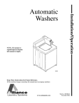
Installation/Operation
Automatic
Washers
Metered and Nonmetered
Para bajar una copia de estas instrucciones
en español, visite www.comlaundry.com.
W446I
Keep These Instructions for Future Reference.
(If this machine changes ownership, this manual must accompany machine.)
www.comlaundry.com
Part No. 201932R5
August 2012
WARNING
For your safety and to reduce the risk of
fire or an explosion, do not store or use
gasoline or other flammable vapors and
liquids in the vicinity of this or any other
appliance.
W022
IMPORTANT: Read the complete
INSTALLATION/OPERATION INSTRUCTIONS
before using the washer.
201932
© Copyright, Alliance Laundry Systems LLC – DO NOT COPY or TRANSMIT
1
Table of
Contents
Safety Information..............................................................................
Explanation of Safety Messages...........................................................
Important Safety Instructions ...............................................................
4
4
4
Installation...........................................................................................
Dimensions and Specifications.............................................................
Before You Start ...................................................................................
Tools ................................................................................................
Installing the Washer ............................................................................
Step 1: Remove the Shipping Brace and Shipping Plug..................
Step 2: Wipe Out Inside of Washtub ...............................................
Step 3: Connect Fill Hoses...............................................................
Step 4: Connect Drain Hose to Drain Receptacle ............................
Step 5: Position and Level the Washer ............................................
Step 6: Plug In the Washer...............................................................
Step 7: Add Water to the Washer ....................................................
Step 8: Check Lid Switch ................................................................
Step 9: Check Installation ................................................................
Vending.................................................................................................
Meter Case .......................................................................................
Slide Extension Assembly – Models through Serial No. 1211........
Slide Extension Assembly – Models Starting Serial No. 1211 .......
Models Prepped for Card Reader.....................................................
Additional Washer Security .............................................................
6
6
7
7
7
7
8
8
10
11
12
13
13
13
14
14
14
15
17
18
Operation.............................................................................................
Operation Instructions for Coin Slide Operated and
Nonmetered Washers .........................................................................
Step 1: Add Detergent......................................................................
Step 2: Load Laundry.......................................................................
Step 3: Close Lid..............................................................................
Step 4: Set Wash Temperature and Fabric/Cycle Selector ..............
Step 5: Start Washer.........................................................................
Indicator Lights ................................................................................
Control Modes .................................................................................
Rapid Advance.................................................................................
Setting Dipswitch.............................................................................
Operation Instructions for Electronic Display Control Washers..........
Step 1: Add Detergent......................................................................
Step 2: Load Laundry.......................................................................
Step 3: Close Lid..............................................................................
Step 4: Choose Small Load, if Desired ............................................
Step 5: Set Fabric Selector ...............................................................
Step 6: Set Wash Temperature.........................................................
Step 7: Insert Money ........................................................................
Indicator Lights ................................................................................
19
19
19
19
19
20
21
21
22
23
23
24
24
24
24
25
25
25
25
26
© Copyright 2012, Alliance Laundry Systems LLC
All rights reserved. No part of the contents of this book may be reproduced or transmitted in any form or by any
means without the expressed written consent of the publisher.
2
© Copyright, Alliance Laundry Systems LLC – DO NOT COPY or TRANSMIT
201932
Operation Instructions for MDC Washers............................................
Step 1: Add Detergent......................................................................
Step 2: Load Laundry.......................................................................
Step 3: Close Lid..............................................................................
Step 4: Choose Small Load, if Desired ............................................
Step 5: Set Fabric Selector and Wash Temperature.........................
Step 6: Insert Money or Card...........................................................
Step 7: Start Washer.........................................................................
Indicator Lights ................................................................................
Operation Instructions for NetMaster Washers ....................................
Step 1: Add Detergent......................................................................
Step 2: Load Laundry.......................................................................
Step 3: Close Lid..............................................................................
Step 4: Choose Small Load, if Desired ............................................
Step 5: Set Fabric Selector ...............................................................
Step 6: Set Wash Temperature.........................................................
Step 7: Insert Money or Card...........................................................
Step 8: Start Washer.........................................................................
Indicator Lights ................................................................................
27
27
27
27
28
28
28
29
29
30
30
30
30
31
31
31
32
32
32
Maintenance ........................................................................................
User-Maintenance Instructions.............................................................
Cold Weather Care...........................................................................
Care of Your Washer .......................................................................
Replacing Hoses...............................................................................
Filter Screens ...................................................................................
Reinstallation of Shipping Materials ...............................................
Motor Overload Protector.....................................................................
33
33
33
33
33
33
33
33
Troubleshooting .................................................................................. 34
Contact Information........................................................................... 36
Installer Checklist................................................................ Back Cover
201932
© Copyright, Alliance Laundry Systems LLC – DO NOT COPY or TRANSMIT
3
Safety Information
Explanation of Safety Messages
Important Safety Instructions
Throughout this manual and on machine decals, you
will find precautionary statements (“DANGER,”
“WARNING,” and “CAUTION”) followed by specific
instructions. These precautions are intended for the
personal safety of the operator, user, servicer, and
those maintaining the machine.
Save These Instructions
DANGER
Indicates an imminently hazardous
situation that, if not avoided, will cause
severe personal injury or death.
WARNING
Indicates a hazardous situation that, if not
avoided, could cause severe personal
injury or death.
CAUTION
Indicates a hazardous situation that, if not
avoided, may cause minor or moderate
personal injury or property damage.
Additional precautionary statements (“IMPORTANT”
and “NOTE”) are followed by specific instructions.
IMPORTANT: The word “IMPORTANT” is used
to inform the reader of specific procedures where
minor machine damage will occur if the procedure
is not followed.
NOTE: The word “NOTE” is used to communicate
installation, operation, maintenance or servicing
information that is important but not hazard
related.
WARNING
To reduce the risk of fire, electric shock,
serious injury or death to persons when
using your washer, follow these basic
precautions:
W023
1. Read all instructions before using the washer.
2. Install the washer according to the
INSTALLATION INSTRUCTIONS. Refer to the
EARTHING (GROUNDING) INSTRUCTIONS
in the INSTALLATION manual for the proper
earthing (grounding) of the washer. All
connections for water, drain, electrical power and
earthing (grounding) must comply with local
codes and be made by licensed personnel when
required. Do not do it yourself unless you know
how!
3. Do not install or store the washer where it will be
exposed to water and/or weather.
4. Do not add the following substances or textiles
containing traces of the following substances to
the wash water: gasoline, kerosene, waxes,
cooking oils, vegetable oils, machine oils, drycleaning solvents, flammable chemicals, thinners
or other flammable or explosive substances.
These substances give off vapors that could
ignite, explode or cause the fabric to catch on fire
by itself.
5. Under certain conditions, hydrogen gas may be
produced in a hot water system that has not been
used for two weeks or more. HYDROGEN GAS
IS EXPLOSIVE. If the hot water system has not
been used for such a period, before using a
washing machine or combination washer-dryer,
turn on all hot water faucets and let the water
flow from each for several minutes. This will
release any accumulated hydrogen gas. THE
GAS IS FLAMMABLE, DO NOT SMOKE OR
USE AN OPEN FLAME DURING THIS TIME.
6. To reduce the risk of an electric shock or fire, DO
NOT use an extension cord or an adapter to
connect the washer to the electrical power
source.
4
© Copyright, Alliance Laundry Systems LLC – DO NOT COPY or TRANSMIT
201932
Safety Information
7. Do not allow children to play on or in the washer.
Close supervision of children is necessary when
the washer is used near children. This appliance
is not intended for use by persons (including
children) with reduced physical, sensory or
mental capabilities, or lack of experience and
knowledge, unless they have been given
supervision or instruction concerning the use of
the appliance by a person responsible for their
safety. This is a safety rule for all appliances.
8. Do not reach into the washer if the washtub or
agitator is moving.
9. Never operate the washer with any guards ,
panels and/or parts removed or broken. DO NOT
tamper with the controls or bypass any safety
devices.
10. DO NOT operate individual units if they have
been separated from a stack unit.
11. Use your washer only for its intended purpose,
washing clothes. Always follow the fabric care
instructions supplied by the garment
manufacturer.
12. Always read and follow manufacturer’s
instructions on packages of laundry and cleaning
aids. To reduce the risk of poisoning or chemical
burns, keep them out of the reach of children at
all times (preferably in a locked cabinet). Heed
all warnings or precautions.
13. Do not use fabric softeners or products to
eliminate static unless recommended by the
manufacturer of the fabric softener or product.
14. Lid MUST BE CLOSED any time the washer is
to agitate or spin. DO NOT bypass the lid switch
by permitting the washer to agitate or spin with
the lid open. A brake will stop the washtub
within seconds if the lid is opened during
spinning. If the washtub does not stop when the
lid is opened, remove the washer from use and
call the service person.
201932
15. Be sure water connections have a shut-off valve
and that fill hose connections are tight. CLOSE
the shut-off valves at the end of each wash day.
16. Keep your washer in good condition. Bumping or
dropping the washer can damage safety features.
If this occurs, have your washer checked by a
qualified service person.
17. Do not repair or replace any part of the washer, or
attempt any servicing unless specifically
recommended in the user-maintenance
instructions or in published user-repair
instructions that you understand and have the
skills to carry out. ALWAYS disconnect the
washer from electrical supply before attempting
any service.
18. Disconnect the power cord by grasping the plug,
not the cord. If the supply cord is damaged, it
must be replaced by a special cord or assembly
available from the manufacturer or its service
agent.
19. Before the washer is removed from service or
discarded, remove the lid to the washing
compartment.
20. Failure to install, maintain, and/or operate this
washer according to the manufacturer’s
instructions may result in conditions which can
produce bodily injury and/or property damage.
NOTE: The WARNING and IMPORTANT
SAFETY INSTRUCTIONS appearing in this
manual are not meant to cover all possible
conditions and situations that may occur. Common
sense, caution and care must be exercised when
installing, maintaining, or operating the washer.
Always contact your dealer, distributor, service agent
or the manufacturer about any problems or conditions
you do not understand.
© Copyright, Alliance Laundry Systems LLC – DO NOT COPY or TRANSMIT
5
Installation
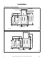
Dimensions and Specifications
Coin Slide Models
21.56 in. (54.76 cm)
Electronic Control Models
22.44 in. (57 cm)
0.44 in.
(1.12 cm)
25.63 in. (65.1 cm)
51 in. (129.54 cm)
Standard Capacity Meter Case
43 in. (109.2 cm)
High Capacity Meter Case
43.875 in. (111.44 cm)
Coin Slide Models
40.38 in. (102.56 cm)
Electronic Control Models
38.19 in. (97 cm)
30.5 in. (74.47 cm)
28.75 in. (73.02 cm)
H
36 in. (91.44 cm)
C
41.25 in. (104.78 cm)
1
26 in. (66.04 cm)
28 in. (71.12 cm)
METERED MODELS
TLW2051N
TLW2051N
1
Pilot Hole
25.63 in. (65.1 cm)
0.44 in.
(1.12 cm)
51 in. (129.54 cm)
40.38 in. (102.56 cm)
30.5 in. (74.47 cm)
28.75 in. (73.02 cm)
H
36 in. (91.44 cm)
C
41.25 in. (104.78 cm)
21.56 in. (54.76 cm)
26 in. (66.04 cm)
28 in. (71.12 cm)
NONMETERED MODELS
TLW2050N
TLW2050N
6
© Copyright, Alliance Laundry Systems LLC – DO NOT COPY or TRANSMIT
201932
Installation
Before You Start
Installing the Washer
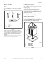
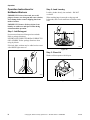
Tools
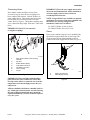
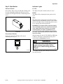
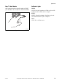
Step 1: Remove the Shipping Brace and
Shipping Plug
For most installations, the basic tools you will need
are:
1
Remove the shipping brace from under the lid.
The shipping plug will be released from the base of the
washer when removing the cardboard base from the
washer. Refer to Figure 2.
2
3
The shipping brace and plug should be saved and must
be reinstalled whenever washer is moved or
transported to a new location. This will prevent
damage to washer components.
Do not tilt washer to front or sides when moving.
4
Refer to User-Maintenance section for instructions on
reinstalling shipping brace and shipping plug.
D074I
D074I
1
2
3
4
Wrench
Screwdriver
Pliers
Level
Figure 1
1
NOTE: If the washer is delivered on a cold day
(below freezing), or is stored in an unheated room
or area during the cold months, do not attempt to
operate it until the washer has had a chance to
warm up.
3
2
IMPORTANT: Install dryer before washer. This
allows room for attaching exhaust duct.
TLW2052N
TLW2052N
1
2
3
Shipping Brace
Shipping Plug
Cardboard Base
Figure 2
201932
© Copyright, Alliance Laundry Systems LLC – DO NOT COPY or TRANSMIT
7
Installation
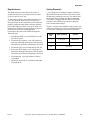
Step 2: Wipe Out Inside of Washtub
Water Supply Requirements
Prior to first wash, use an all purpose cleaner or a
detergent and water solution and a damp cloth to
remove shipping dust from inside of washtub.
Water supply faucets must fit standard 3/4 inch
(19.1 mm) female garden hose couplings. DO NOT
USE SLIP-ON OR CLAMP-ON CONNECTIONS.
NOTE: Water supply faucets should be readily
accessible to permit turning them off when washer
is not being used.
Recommended cold water temperature is 50° to 75°
Fahrenheit (10° to 24° Celsius). Recommended
maximum hot water temperature is 125° Fahrenheit
(51° Celsius). Warm water is a mixture of hot and cold
water. Warm water temperature is dependent upon the
water temperature and the pressure of both the hot and
cold water supply lines.
WARNING
W396I
W396I
To prevent personal injury, avoid contact
with inlet water temperatures higher than
125° Fahrenheit (51° Celsius) and hot
surfaces.
W748
Figure 3
Pressure must be a minimum of 20 to a maximum of
120 pounds per square inch (138 to 827 kPa) static
pressure measured at the faucet.
Step 3: Connect Fill Hoses
WARNING
Under certain conditions, hydrogen gas
may be produced in a hot water system
that has not been used for two weeks or
more. HYDROGEN GAS IS EXPLOSIVE. If
the hot water system has not been used
for such a period and before using the
washer, turn on all hot water faucets and
let the water flow from each for several
minutes. This will release any
accumulated hydrogen gas. The gas is
flammable. Do not smoke or use an open
flame during this time.
NOTE: Water pressure under 20 pounds per
square inch (138 kPa) will cause an extended fill
time in the washer.
Turn on the water supply faucets and flush the lines for
approximately two minutes to remove any foreign
materials that could clog the screens in the water
mixing valve. (This is especially important when
installing your washer in a newly constructed or
renovated building.)
W029
Mixing Valve Flow Rates
Pressure
(psi)
35
55
HOT
gallons per
minute
(liters per
minute)
COLD
gallons per
minute
(liters per
minute)
WARM
gallons per
minute
(liters per
minute)
2.4
(9.1)
3.5
(13.2)
4.5
(17.0)
6.2
(23.5)
7.15
(27.1)
9.2
(34.8)
Table 1
8
© Copyright, Alliance Laundry Systems LLC – DO NOT COPY or TRANSMIT
201932
Installation
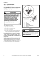
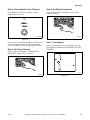
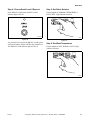
Connecting Hoses
Insert rubber washers and filter screens (from
accessories bag) in water fill hose couplings (two
hoses supplied with washer). Connect fill hoses to
water supply faucets. Then connect the hoses to the
hot and cold valve connections at the rear of the
washer. Refer to Figure 4. Thread hose couplings onto
valve connections finger tight. Then turn 1/4 turn with
pliers.
IMPORTANT: DO NOT cross thread or
overtighten couplings.
1
NOTE: Longer fill hoses are available (as optional
equipment at extra cost) if the hoses (supplied with
the washer) are not long enough for the
installation. Order hoses as follows:
No. 20617 Fill Hose (8 feet) (2.44 m)
No. 20618 Fill Hose (10 feet) (3.05 m)
Risers
4
3
COLD
HOT
2
IMPORTANT: Turn off water supply faucets after
check-out and demonstration. Owner should turn
off water supply whenever there will be an
extended period of non-use.
C
H
Risers (or air cushions) may have to be installed if the
pipes knock or pound when flow of water stops. The
risers are more efficient when installed as close as
possible to the water supply faucets. Refer to Figure 5.
1
7
5
6
TLW1988N
TLW1988N
1
2
3
4
5
6
7
Filter Screen (Screen must be facing
outward)
Fill Hose
Rubber Washer (Plain)
Cold Water Connection
Hot Water Connection
Hose Coupling
Faucet
Figure 4
IMPORTANT: Hoses and other natural rubber
parts deteriorate after extended use. Hoses may
develop cracks, blisters or material wear from the
temperature and constant high pressure they are
subjected to.
2
W005I
W005I
1
2
Risers (Air cushions)
Water Supply Faucets
Figure 5
All hoses should be checked on a monthly basis for
any visible signs of deterioration. Any hose showing
the signs of deterioration listed above should be
replaced immediately. All hoses should be replaced
every five years.
201932
© Copyright, Alliance Laundry Systems LLC – DO NOT COPY or TRANSMIT
9
Installation
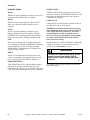
Step 4: Connect Drain Hose to Drain
Receptacle
If necessary, follow the instructions for your type of
drain receptacle (high standpipe or low standpipe) to
properly install the drain hose.
Drain Facilities
High Standpipe Installation
IMPORTANT: The drain hose installation is a very
important factor in the washer installation. If care
is not taken when the drain hose is installed, a
siphoning action can be started which will cause
water to be siphoned from the washer during the
cycle.
NOTE: No. 562P3 Siphon Break Kit and No. 25863
Hose Coupling are not required for this type of
installation.
1
End of drain hose should never be in water as
siphoning action can be started that will cause
water to be siphoned back into the washer.
2
1
MAXIMUM
STANDPIPE
HEIGHT NOT TO
EXCEED 5 feet
(1.5 m)
3
RECOMMENDED
STANDPIPE
HEIGHT
36 inches
MINIMUM
(91.44 cm)
W296I
W296I
1
2
3
2
Drain Hose
Cut Drain Hose off at This End to Fit the
Washer Installation
Standpipe
Figure 7
W294I
W294I
1
2
{
The curved end of drain hose MUST be installed
even with or above the height of the cabinet top of
the washer to prevent siphoning. Refer to Figure 6.
Drain Hose
Standpipe
IMPORTANT: Drain receptacle must be capable of
handling a minimum of 1-1/2 inch (3.8 cm) outside
diameter drain hose.
Figure 6
The standpipe or drain receptacle must be capable of
handling a minimum of 1-1/2 inches (3.8 cm) outside
diameter drain hose. The drain hose should fit loose
within the standpipe (it should not be snug fit). Never
install the drain hose into a “sealed” drain system as
air cannot escape and will restrict the water from being
drained from the washer. A sealed drain system may
also allow water to be pumped back into the washer
during agitation. Both of these conditions may result
in flooding of the washer.
Remove the drain hose from its shipping position on
the rear of the washer by unhooking the hose from the
retainer clamp.
10
© Copyright, Alliance Laundry Systems LLC – DO NOT COPY or TRANSMIT
201932
Installation
Low Standpipe Installation
If the drain facility is lower than the cabinet top, a
siphon break kit, Part No. 562P3, must be installed in
the drain hose to prevent siphoning action and drain
hose MUST be cut to fit the washer installation. Refer
to Figure 8. Use one No. 25863 Hose Coupling to
splice hose. The No. 562P3 Siphon Break Kit and No.
25863 Hose Coupling are available as optional
equipment at extra cost through an authorized dealer
or parts distributor. Installation instructions are
supplied with the kit.
OPTIONAL: Raise the standpipe to the recommended
height of 36 inches (91.44 cm).
IMPORTANT: Drain receptacle must be capable of
handling a minimum of 1-1/2 inch (3.8 cm) outside
diameter drain hose.
1
2
If washer is not level, tilt washer back to access the
front leveling legs. Loosen the locknuts and adjust legs
by screwing into or out of washer base.
Once adjusted, tilt the washer forward on front legs
and lower back down into position to set the rear selfleveling legs.
Washer must not rock. After washer is at desired
height, tighten locknuts securely against bottom of
washer base. If these locknuts are not tight, washer
will not remain stationary during operation.
Improper installation or flexing of weak floor will
cause excessive vibration.
Do not slide washer across floor once the leveling legs
have been extended, as legs and base could become
damaged.
NOTE: For areas with uneven floors, a No. 566P3
Adjustable Rear Leg Extension Kit is available as
optional equipment at extra cost.
Verify that unit does not rock.
5
1
2
{
4
3
3
W295I
W295I
1
2
3
4
5
Drain Hose Elbow
562P3 Siphon Break Kit
Standpipe
Cut Hose in This Area and Install No. 25863
Hose Coupling
25863 Hose Coupling
Figure 8
Step 5: Position and Level the Washer
Position washer so it has sufficient clearance for
installation and servicing.
6
5
4
TLW2100N
TLW2053N
1
2
3
4
5
6
Washer Base
Locknut
Leveling Leg
Rubber Cup
1/2 inch (12.7 mm) Clearance Between
Washers
Level
Figure 9
Place washer in position on a clean, dry, and
reasonably firm floor. Installing the washer on any
type of carpeting is not recommended.
Place rubber cups on all four leveling legs.
Place a level on the cabinet top and check if the
washer is level from side to side and front to back.
201932
© Copyright, Alliance Laundry Systems LLC – DO NOT COPY or TRANSMIT
11
Installation
Step 6: Plug In the Washer
Electrical Requirements
(120 Volt, 60 Hertz with 3-Prong Grounding Plug)
2
3
1
NOTE: The wiring diagram is located in the
control hood.
120±12
V.A.C.
0 V.A.C.
WARNING
To reduce the risk of fire, electric shock,
serious injury or death, all wiring and
grounding MUST conform with the latest
edition of the National Electrical Code,
ANSI/NFPA No. 70, and such local
regulations as might apply. It is the
customer’s responsibility to have the
wiring, fuses and circuit breakers
installed by a qualified electrician to make
sure adequate electrical power is
available to the washer.
W518
When plugging in the washer:
• DO NOT overload circuits.
• DO NOT use an extension cord.
• DO NOT use an adapter.
• DO NOT operate other appliances on the same
circuit. Use separately fused 15 Amp circuits.
The washer is designed to be operated on a separate
branch, polarized, three-wire, effectively grounded,
120 Volt, 60 Hertz, AC (alternating current), circuit
protected by a 15 ampere fuse, equivalent fusetron or
circuit breaker.
120±12
V.A.C.
4
5
Standard 120 Volt, 60 Hertz
3-Wire Effectively
Grounded Circuit
DRY2022N
1
2
3
4
5
L1
Ground
Neutral Side
Round Grounding Prong
Neutral
Figure 10
WARNING
To reduce the risk of an electric shock or
fire, DO NOT use an extension cord or an
adapter to connect the washer to the
electric power source.
W082
The three-prong grounding plug on the power cord
should be plugged directly into a polarized three-slot
effectively grounded receptacle rated 110/120 Volts
AC (alternating current) 15 Amps. Refer to Figure 10
to determine correct polarity of the wall receptacle.
12
© Copyright, Alliance Laundry Systems LLC – DO NOT COPY or TRANSMIT
201932
Installation
Grounding Instructions
The washer must be grounded. In the event of
malfunction or breakdown, grounding will reduce the
risk of electric shock by providing a path of least
resistance for electric current.
The washer is equipped with a cord having an
equipment-grounding conductor and a three-prong
grounding plug. The plug must be plugged into an
appropriate outlet that is properly installed and
grounded in accordance with all local codes and
ordinances.
TLW2056N
TLW2056N
Figure 11
WARNING
Improper connection of the equipmentgrounding conductor can result in a risk
of electric shock. Check with a qualified
electrician or service person if you are in
doubt as to whether the washer is
properly grounded.
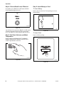
Step 8: Check Lid Switch
Washer should stop filling, agitating and spinning
when lid is opened.
W327
• DO NOT modify the plug provided with the
washer – if it will not fit the outlet, have a proper
outlet installed by a qualified electrician.
• If the laundry room’s electrical supply does not
meet the above specifications and/or if you are
not sure the laundry room has an effective
ground, have a qualified electrician or your local
electrical utility company check it and correct
any problems.
TLW1974N
WARNING
TLW1974N
Figure 12
Any disassembly requiring the use of
tools must be performed by a suitably
qualified service person.
Step 9: Check Installation
W299
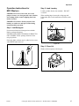
Step 7: Add Water to the Washer
To prevent damage to pump, do not run washer before
adding at least one quart water to the tub. If the washer
is run before any water is added, the pump seal may
overheat, causing the pump to leak. Once installed, the
water retained in the drain system from the previous
cycle will provide sufficient cooling to prevent pump
seal damage.
Refer to Installer Checklist on the back cover of this
manual and make sure that washer is installed
correctly.
Run washer through one complete cycle to make sure
it is operating properly.
NOTE: The agitator should not be removed except
for service. The washtub is designed to be selfcleaning.
201932
© Copyright, Alliance Laundry Systems LLC – DO NOT COPY or TRANSMIT
13
Installation
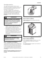
Vending
Meter Case
The factory mounted coin meter case does not include
the service door lock, coin slide, coin drawer, coin
drawer lock or keys. These parts must be ordered (at
extra cost) according to the purchaser’s requirements
direct from the manufacturer of your choice.
2. If installing a Greenwald coin slide, position
extension lever (to be installed on extension
bracket) with arm that has one star facing down.
Refer to Figure 13.
Greenwald
Coin Slide
NOTE: On models with standard capacity meter
case and high capacity meter case models starting
with Serial Nos. beginning 1010, you have the
option of using a screw type lock or a 1/4 turn lock
on the meter case service door. If you choose to use
a screw lock, then the special bracket (located
inside the meter case) must be used. DO NOT use
the special bracket if a 1/4 turn lock is used. High
capacity meter case models with Serial Nos.
beginning 0910 through 1010 use 1/4 turn lock only.
Coin Drawer Security (Models with Standard
Capacity Meter Case and High Capacity Meter
Case models starting with Serial Nos. beginning
1010 Only) – For additional security, drill out the two
pilot holes on each side of the front of the meter case
to 1/4 or 5/16 inch (6.4 or 7.9 mm) holes and install a
bicycle lock through these holes.
NOTE: An 8 in. (20.32 cm) coin drawer is required
for coin operated electronic control models with
standard capacity meter case and high capacity
meter case models starting with Serial Nos.
beginning 1010. High capacity meter case models
with Serial Nos. beginning 0910 through 1010
require a 7.21 in. (18.31 cm) coin drawer.
Slide Extension Assembly – Models
through Serial No. 1211
(Coin Slide Models with Standard Capacity Meter
Case and High Capacity Meter Case models
starting with Serial Nos. beginning 1010 Only)
NOTE: High capacity meter case models with
Serial Nos. beginning 0910 through 1010 require a
coin slide with a switch installed on it.
1. Remove slide extension parts from parts
accessories bag included in unit.
14
Monarch or
ESD Coin Slide
One Star
Two Stars
TLW2088N
Figure 13
3. If installing a Monarch or ESD coin slide,
position lever with arm that has two stars facing
down. Refer to Figure 13.
4. Install extension lever with rounded corner facing
away from extension bracket using bolt, one or
two flat washers (shims) (use number of washers
included in kit) and nut. Refer to Figure 14. Make
sure washers are flat against bracket.
Spring
One or Two
Flat Washers (Shims)
Bolt
Rounded Corner
Nut
Loops
Extension Bracket
Extension Lever
TLW2089N
Star(s) Facing Down
TLW2089N
Figure 14
5. Torque nut between 2 and 2.26 Nm (18 and 20
inch-pounds), or tighten nut firmly.
6. Install extension spring in bracket hole and hole in
upper arm of lever. Refer to Figure 14.
7. Bend loops closed after installation.
8. Check to make sure the lever swings freely.
© Copyright, Alliance Laundry Systems LLC – DO NOT COPY or TRANSMIT
201932
Installation
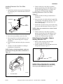
Installing Extension Onto Coin Slide:
Option 1
1. Install slide extension onto top of coin slide using
two remaining screws and lockwashers. Refer to
Figure 15.
Attaching
Screws
6. Check to make sure coin slide is operating
properly by inserting coins and starting a cycle.
The IN USE light will turn on, or flash if it is
already on, to indicate proper operation.
Installing Extension Onto Coin Slide:
Option 2
1. Install coin slide according to manufacturer’s
instructions.
2. Insert coins into coin slide and slowly push slide
in. Stop before coins fall into coin box. This will
allow installing extension through meter case
service door opening.
Lockwashers
Coin Slide
Slide
Extension
3. Install slide extension onto top of coin slide using
two screws and lockwashers. Refer to Figure 15.
NOTE: Make sure extension lever is above switch
activation lever.
TLW1564K
Figure 15
2. Insert coins and partially extend coin slide.
3. Insert coin slide on its side through meter case
opening. Then rotate 90 degrees to its proper
orientation.
4. Return coin slide and hook slide pins onto meter
case.
5. Continue coin slide installation according to
manufacturer’s instructions.
4. Check to make sure coin slide is operating
properly by inserting coins and starting a cycle.
The IN USE light will turn on, or flash if it is
already on, to indicate proper operation.
Slide Extension Assembly – Models
Starting Serial No. 1211
1. Remove slide extension parts from parts
accessories bag included in unit.
2. Install extension lever with arm that has one star
facing down. Refer to Figure 17.
NOTE: During coin slide installation, make sure
activation lever is up and off the switch. Refer to
Figure 16.
1
One Star
TLW2088N
Figure 17
NOTE: If more switch down-force is required,
install lever with arm that has two stars facing
down to provide additional switch travel.
TLW2090N
TLW2090N
1
Lever Off Switch
Figure 16
201932
© Copyright, Alliance Laundry Systems LLC – DO NOT COPY or TRANSMIT
15
Installation
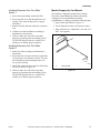
3. Install extension lever with rounded corner
facing away from extension bracket using bolt,
washer and nut. Refer to Figure 18.
Bolt
5. Install coin slide extension assembly onto top of
coin slide using two remaining screws and
lockwashers. Refer to Figure 20.
Coin Slide Extension
Assembly
Washer
Rounded
Corner
Nut
Extension
Bracket
TLW2156N
TLW1580K
Figure 20
Extension
Lever
TLW1580K
Figure 18
4. Install extension bracket and lever assembly onto
coin slide bracket using two screws and locknuts.
Refer to Figure 19.
6. Before installing coin slide and extension, make
sure ground wire is tucked under control shield to
provide clearance for coin slide. Refer to
Figure 21.
Ground Wire Placement
IMPORTANT: Install coin slide bracket with side
marked "A" facing up and toward extension
bracket and lever assembly. Refer to Figure 19.
Extension Bracket and
Lever Assembly
Coin Slide Bracket Letter "A"
TLW2157N
Figure 21
TLW2155N
Figure 19
16
© Copyright, Alliance Laundry Systems LLC – DO NOT COPY or TRANSMIT
201932
Installation
Installing Extension Onto Coin Slide:
Option 1
1. Insert coins and partially extend coin slide.
2. Insert coin slide on its side through meter case
opening. Then rotate 90 degrees to its proper
orientation.
3. Return coin slide and hook slide pins onto meter
case.
4. Continue coin slide installation according to
manufacturer’s instructions.
Models Prepped for Card Reader
The machine is shipped from the factory with the
Electronic Control Diagnostic Harness Assembly
unplugged. To avoid unauthorized manual
programming or vending, perform the following steps.
1. Open control panel. Refer to Figure 22.
2. Locate diagnostic harness on electronic control.
3. Plug connectors for “white/black” wire and “red/
blue” wire together.
5. Check to make sure coin slide is operating
properly by inserting coins and starting a cycle.
The IN USE light will turn on, or flash if it is
already on, to indicate proper operation.
1
Installing Extension Onto Coin Slide:
Option 2
1. Install coin slide according to manufacturer’s
instructions.
2. Insert coins into coin slide and slowly push slide
in. Stop before coins fall into coin box. This will
allow installing extension through meter case
service door opening.
3. Install slide extension onto top of coin slide using
two screws. Refer to Figure 20.
4. Check to make sure coin slide is operating
properly by inserting coins and starting a cycle.
The IN USE light will turn on, or flash if it is
already on, to indicate proper operation.
201932
FLW6R
FLW6R
1
Control Panel
Figure 22
© Copyright, Alliance Laundry Systems LLC – DO NOT COPY or TRANSMIT
17
Installation
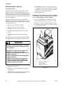
Additional Washer Security
(Coin Models Only)
Located on the service door of the washer is a flat
Phillips head screw. During shipment, this screw is
used to attach the service door to the meter case. For
additional security, this screw can be reinstalled inside
the control hood of your washer. Refer to instructions
below for installation.
Tamper-resistant screws also can be installed for
additional security. Tamper-resistant screws, bits and
bit holder are available as optional equipment at extra
cost. Part numbers are:
• Bit (No. 8 screws) Part No. 281P4
4. Insert Phillips head screw down through double
“D” hole in left rear corner of cabinet top (inside
control hood) until it engages retainer nut located
on left rear corner gusset of cabinet.
5. Finger tighten screw.
IMPORTANT: Do not use a power driver to tighten
screw. Torque of a power driver could over-tighten
screw causing damage to cabinet assembly.
6. Secure control panel to control hood using two
No. 8 tamper-resistant screws, Part No. 35528.
7. Remove two screws holding front panel to base
of washer and install two No. 12 tamper-resistant
screws, Part No. 35527.
• Bit (No. 12 screws) Part No. 282P4
• Bit Holder (3/8 drive) Part No. 24161
2
1
• Control panel tamper-resistant screw Part No.
35528
• Front panel tamper-resistant screw Part No.
35527
The following list is the procedure required to install
the Phillips head screw and tamper-resistant screws:
WARNING
Any disassembly requiring the use of tools
must be performed by a suitably qualified
service person.
W299
To reduce the risk of electric shock, fire,
explosion, serious injury or death:
• Disconnect electric power to the washer
before servicing.
• Never start the washer with any guards/
panels removed.
• Whenever ground wires are removed
during servicing, these ground wires
must be reconnected to ensure that the
washer is properly grounded.
W003
1. Remove the Phillips head screw from service
door (refer to Figure 23).
2. Remove two screws holding control panel to
control hood.
W276I
3
W276I
1
2
3
35528 No. 8 Screws
Double “D” Hole
35527 No. 12 Screws
Figure 23
3. Tilt control panel forward and lay on a protective
pad to prevent scratching of cabinet top.
18
© Copyright, Alliance Laundry Systems LLC – DO NOT COPY or TRANSMIT
201932
Operation
Operation Instructions for Coin
Slide Operated and Nonmetered
Washers
Step 2: Load Laundry
Load dry clothes loosely into washtub – DO NOT
overload!
IMPORTANT: Prior to first wash, use an allpurpose cleaner or a detergent and water solution
and a damp cloth to remove shipping dust from
inside of washtub.
When washing large items such as shag rugs and
bedspreads, add several small items to balance wash
load.
IMPORTANT: Remove all sharp objects from
laundry to avoid tears and rips to items during
normal machine operation.
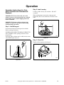
Step 1: Add Detergent
Pour measured amount of detergent into washtub.
Refer to package directions.
NEVER POUR UNDILUTED BLEACH DIRECTLY
ON LAUNDRY. Follow package directions when
using bleach.
W392I
If desired, fabric softener may be added to rinse water
when RINSE light comes on.
Figure 25
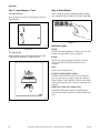
Step 3: Close Lid
Washer will not operate with lid open.
W395I
Figure 24
201932
W394I
Figure 26
© Copyright, Alliance Laundry Systems LLC – DO NOT COPY or TRANSMIT
19
Operation
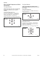
Step 4: Set Wash Temperature and Fabric/
Cycle Selector
One Speed Washers
NOTE: Wash temperature and cycle settings may
be changed any time before first wash fill is
complete.
Setting Wash Temperature/Cycle
Set at either *HOT/NORMAL, *WARM/PERM
PRESS, *COLD/SPECIAL, or HOT/NORMAL,
WARM/PERM PRESS, COLD/SPECIAL.
Two Speed Washers
NOTE: Wash temperature and fabric selector
settings may be changed any time before first wash
fill is complete.
Setting Wash Temperature
Set at HOT (COLD rinse), WARM (COLD rinse) or
COLD (COLD rinse).
TWO SPEED
WASHERS
Settings with asterisk (*) are Energy Saving Cycles.
ONE SPEED
WASHERS
WARM
HOT
COLD
WASH TEMPERATURE
WARM PERM PRESS
TLW2046N
COLD
SPECIAL
HOT
NORMAL
Figure 28
Setting Fabric Selector
Set Regular loads at *NORMAL, *PERM PRESS,
NORMAL or PERM PRESS. Set Delicate loads at
*DELICATE or DELICATE.
COLD
SPECIAL
HOT
NORMAL
WARM
PERM PRESS
TLW2045N
Figure 27
Settings with asterisk (*) are Energy Saving Cycles.
TWO SPEED
WASHERS
PERM PRESS
NORMAL
DELICATE
NORMAL
DELICATE
PERM PRESS
FABRIC SELECTOR
TLW2083N
TLW2083N
Figure 29
20
© Copyright, Alliance Laundry Systems LLC – DO NOT COPY or TRANSMIT
201932
Operation
Step 5: Start Washer
Indicator Lights
Metered Models
IN USE
Insert money. Place coin(s) in slide and carefully push
in as far as possible and then pull slide out as far as
possible. (IN USE light will come on indicating start of
cycle.)
This light will remain on while washer is in use.
RINSE
This light will be on during the rinse portion of the
cycle.
SPIN
This light will be on during the rinse/final spin only.
Washer will stop automatically at end of cycle. (SPIN
and IN USE lights will go out indicating end of cycle.)
Leave lid open after removing laundry.
W297I
Figure 30
Nonmetered Models
IMPORTANT: If washer fails to operate properly
after installation, make sure electrical service and
water supply faucets are turned on. Are all the
controls properly set? Have a qualified service
person refer to the wiring diagram (located inside
of washer control hood), check for broken, loose or
incorrect wiring.
Should washer stop, but IN USE, RINSE or SPIN light
remain on, the motor overload protector may have
cycled. Refer to Maintenance section.
Push start switch (IN USE light will come on
indicating start of cycle.)
WARNING
To reduce the risk of bodily injury, do not
remove laundry from washer until all
lights are out, and all moving parts have
stopped.
W092
TLW2048N
Figure 31
201932
The washer will stop (pause) shortly before the first
spin and final spin.
© Copyright, Alliance Laundry Systems LLC – DO NOT COPY or TRANSMIT
21
Operation
Control Modes
Error Mode
Power-Up Mode
In Error Mode, the IN USE LED flashes to display fill
and drain errors (refer to paragraphs below). Error
Mode can only be exited by powering down washer.
The Error Mode can be turned off by setting dipswitch
2 to the CLOSED position. Refer to Table 1.
The control enters this mode after power is applied to
the washer. In Power-Up Mode, the control will detect
the state it was in at power-down to determine what
mode to enter. After the control completes operation in
the Power-Up Mode, it will enter either the Ready,
Test or Run Modes.
Ready Mode
In Ready Mode, the control will wait for the vend to be
satisfied before entering Run Mode.
Run Mode
In Run Mode, the control is running a cycle. The IN
USE LED will be lit. For metered models, any time the
control receives a coin slide pulse during a cycle, the
IN USE LED will flash briefly to indicate the coin
input. For nonmetered models, any time the control
receives a pulse from the push-to-start switch during a
cycle, the IN USE LED will flash briefly to indicate
the push-to-start input.
Lid Open Mode
The control enters Lid Open Mode when the lid is
opened during Run Mode. All cycle activity is
stopped. The cycle time count down stops unless the
lid is opened during the last three minutes of the final
spin step. In this case the time will continue to count
down.
Fill Error
A Fill Error will occur if the tub does not fill within 62
minutes of the start of the cycle. A Fill Error is
indicated by the control flashing the IN USE LED
twice separated by a one and a half second pause until
the control is powered down. If Error Mode is turned
off (refer to Table 1), the fill error will not occur and
the control will continue to wait for the fill level to be
reached.
Drain Error
A Drain Error will occur if the tub is not empty after a
spin cycle. A Drain Error is indicated by the control
flashing the IN USE LED three times separated by a
one and a half second pause until the control is
powered down. If Error Mode is turned off (refer to
Table 1), the drain error will not occur and the machine
cycle will advance to the next cycle step as though the
water had been pumped out.
End of Cycle Mode
The control enters End of Cycle Mode when a cycle is
complete. The IN USE LED will be off. The control
will remain in this mode until the lid is opened or vend
has been satisfied.
22
© Copyright, Alliance Laundry Systems LLC – DO NOT COPY or TRANSMIT
201932
Operation
Rapid Advance
Setting Dipswitch
The Rapid Advance feature allows the owner to
quickly advance into a cycle and advance an active
cycle to a specific cycle step.
Cycle settings can be changed using the 8-Position
dipswitch mounted on the control. The control reads
the dipswitch settings at power-up. The control must
be powered down to change the dipswitch settings.
The control is shipped from the factory with all the
switches in the OPEN position. Refer to the table
below for dipswitch settings.
To enter Rapid Advance and advance through each
cycle step, open the meter case service door (on
metered models) or the control hood (on nonmetered
models), unplug the white bullet connector with the
black/white and gray/yellow wires on the hood wire
harness for at least one second, and then reconnect it.
Each time the connector is unplugged and
reconnected, the control will advance through the
following steps:
• From Ready Mode, cycle will advance to wash
fill (start of cycle).
• From wash fill or agitate, cycle will advance to
wash spin following a short pause. Wait for pause
and washer to spin before advancing to next step.
• From wash spin, cycle will advance to rinse fill.
• From rinse fill or agitate, cycle will advance to
final spin following a short pause. Wait for pause
and washer to spin before advancing to next step.
Switch 1 is used to select whether a long or short cycle
will be used. Switch 2 is used to turn Error Mode on or
off. Switches 3 through 8 are not used at this time.
Switch
No.
Open (Default)
Closed
1
Long Cycle
Short Cycle
2
Error Mode On
Error Mode Off
3-8
Not Used
Table 2
• From final spin, cycle will advance to End of
Cycle Mode.
• Open lid to clear End of Cycle Mode and return
to Ready Mode.
201932
© Copyright, Alliance Laundry Systems LLC – DO NOT COPY or TRANSMIT
23
Operation
Operation Instructions for
Electronic Display Control Washers
IMPORTANT: Prior to first wash, use an allpurpose cleaner or a detergent and water solution
and a damp cloth to remove shipping dust from
inside of washer.
Step 2: Load Laundry
Load dry clothes loosely into washtub – DO NOT
overload!
When washing large items such as shag rugs and
bedspreads, add several small items to balance wash
load.
IMPORTANT: Remove all sharp objects from
laundry to avoid tears and rips to items during
normal machine operation.
Step 1: Add Detergent
Pour measured amount of detergent into washtub.
Refer to package directions.
NEVER POUR UNDILUTED BLEACH DIRECTLY
ON LAUNDRY. Follow package directions when
using bleach.
If desired, fabric softener may be added to rinse water
when RINSE light comes on.
W392I
Figure 33
Step 3: Close Lid
Washer will not operate with lid open.
W395I
Figure 32
H338I
Figure 34
24
© Copyright, Alliance Laundry Systems LLC – DO NOT COPY or TRANSMIT
201932
Operation
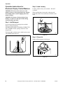
Step 4: Choose Small Load, if Desired
Step 6: Set Wash Temperature
Press SMALL LOAD button. SMALL LOAD
indicator light will be lit.
Push touchpad for HOT, WARM or COLD. Light
indicates selection.
TLW2049N
Figure 35
W338IE1C
Figure 37
Any time the lid is opened, the SMALL LOAD option
will turn off and the washer will fill to the normal
level. The SMALL LOAD indicator light will be off.
Step 5: Set Fabric Selector
Step 7: Insert Money
Insert coin(s) in coin slot. Check pricing as seen on
digital display. LID MUST BE CLOSED TO START
WASHER.
Push touchpad for NORMAL, PERM PRESS or
DELICATES. Light indicates selection.
W387I
W338IE0B
Figure 36
201932
Figure 38
© Copyright, Alliance Laundry Systems LLC – DO NOT COPY or TRANSMIT
25
Operation
Indicator Lights
INSERT COINS
WASH
WASH is lit at the beginning of a Wash cycle and will
remain lit until the Wash cycle is complete.
INSERT COINS is lit to prompt the user for coins to
satisfy the vend price. When INSERT COINS is lit, the
three digits and decimal point show the vend price
remaining to be satisfied.
RINSE
UNBALANCE
RINSE is lit at the beginning of the Rinse or Extra
Rinse cycle and will remain lit until the cycle is
complete.
UNBALANCE is lit and will flash when the washer is
in a Spin mode and the lid is opened.
SOAK
IMPORTANT: If washer fails to operate properly
after installation, make sure electrical service and
water supply faucets are turned on. Are all the
controls properly set? Have a qualified service
person refer to the wiring diagram (located inside
of washer control hood) and check for broken,
loose or incorrect wiring.
SOAK is lit at the beginning of all Pause cycles.
During a Wash Pause cycle, the display will light
“WASH SOAK” and during a Rinse or Extra Rinse
Pause cycle, the display will light “RINSE SOAK.”
SPIN
SPIN is lit for all Spin cycles. During a Wash Spin
cycle, the display will light “WASH SPIN” and during
an Extra Rinse Spin Cycle, the display will light
“RINSE SPIN”. At the beginning of Final Spin, the
display will light “SPIN.”
PRICE
PRICE is lit to indicate that value displayed is the
vend price remaining to be satisfied. Once the vend
price is satisfied, the word “PRICE” will go off.
Should washer stop, but IN USE, RINSE or SPIN light
remain on, the motor overload protector may have
cycled. Refer to Maintenance section.
WARNING
To reduce the risk of bodily injury, do not
remove laundry from washer until all
lights are out, and all moving parts have
stopped.
W092
TIME REMAINING
TIME REMAINING is lit to indicate that the number
displayed by two digits and the colon is the time
remaining in the current cycle. It will light at the start
of the cycle and remain lit until the cycle is completed.
26
The washer will stop (pause) shortly before the first
spin and final spin.
© Copyright, Alliance Laundry Systems LLC – DO NOT COPY or TRANSMIT
201932
Operation
Operation Instructions for
MDC Washers
Step 2: Load Laundry
IMPORTANT: Prior to first wash, use an allpurpose cleaner, or a detergent and water solution,
and a damp cloth to remove shipping dust from
inside of washer.
Load dry clothes loosely into washtub – DO NOT
overload!
When washing large items such as shag rugs and
bedspreads, add several small items to balance wash
load.
IMPORTANT: Remove all sharp objects from
laundry to avoid tears and rips to items during
normal machine operation.
Step 1: Add Detergent
Pour measured amount of detergent into washtub.
Refer to package directions.
NEVER POUR UNDILUTED BLEACH DIRECTLY
ON LAUNDRY. Follow package directions when
using dry bleach.
If desired, fabric softener may be added to rinse water
when RINSE light comes on.
W392I
Figure 40
Step 3: Close Lid
Washer will not operate with lid open.
W395I
Figure 39
H338I
Figure 41
201932
© Copyright, Alliance Laundry Systems LLC – DO NOT COPY or TRANSMIT
27
Operation
Step 4: Choose Small Load, if Desired
Step 6: Insert Money or Card
If available, press SMALL LOAD button. SMALL
LOAD indicator light will be lit.
To Insert Money
Insert coin(s) in coin slot. Check pricing as seen on
digital display.
TLW2049N
Figure 42
Any time the lid is opened, the SMALL LOAD option
will turn off and the washer will fill to the normal
level. The SMALL LOAD indicator light will be off.
Step 5: Set Fabric Selector and Wash
Temperature
W387I
Figure 44
To Insert Card
Insert card into opening.
Push touchpad for NORMAL/HOT, NORMAL/
WARM, PERM PRESS/WARM or DELICATES/
COLD. Light indicates selection.
FLW1920N
FLW1920N
Figure 43
DRY1927N
Figure 45
28
© Copyright, Alliance Laundry Systems LLC – DO NOT COPY or TRANSMIT
201932
Operation
Step 7: Start Washer
Indicator Lights
After vend price has been satisfied, push the START
pad. LID MUST BE CLOSED TO START WASHER.
WASH
WASH is lit at the beginning of a Wash cycle and will
remain lit until the Wash cycle is complete.
RINSE
RINSE is lit at the beginning of the Rinse cycle and
will remain lit until the cycle is complete.
SPIN
SPIN is lit for all Spin cycles.
FLW1923N
Figure 46
201932
© Copyright, Alliance Laundry Systems LLC – DO NOT COPY or TRANSMIT
29
Operation
Operation Instructions for
NetMaster Washers
Step 2: Load Laundry
IMPORTANT: Prior to first wash, use an allpurpose cleaner, or a detergent and water solution,
and a damp cloth to remove shipping dust from
inside of washer.
Load dry clothes loosely into washtub – DO NOT
overload!
When washing large items such as shag rugs and
bedspreads, add several small items to balance wash
load.
IMPORTANT: Remove all sharp objects from
laundry to avoid tears and rips to items during
normal machine operation.
Step 1: Add Detergent
Pour measured amount of detergent into washtub.
Refer to package directions.
NEVER POUR UNDILUTED BLEACH DIRECTLY
ON LAUNDRY. Follow package directions when
using dry bleach.
If desired, fabric softener may be added to rinse water
when RINSE light comes on.
W392I
Figure 48
Step 3: Close Lid
Washer will not operate with lid open.
W395I
Figure 47
H338I
Figure 49
30
© Copyright, Alliance Laundry Systems LLC – DO NOT COPY or TRANSMIT
201932
Operation
Step 4: Choose Small Load, if Desired
Step 5: Set Fabric Selector
Press SMALL LOAD button. SMALL LOAD
indicator light will be lit.
Push touchpad for NORMAL, PERM PRESS or
DELICATES. Light indicates selection.
W524I
TLW2049N
Figure 50
Any time the lid is opened, the SMALL LOAD option
will turn off and the washer will fill to the normal level.
The SMALL LOAD indicator light will be off.
W524I
Figure 51
Step 6: Set Wash Temperature
Push touchpad for HOT, WARM or COLD. Light
indicates selection.
W525I
W525I
Figure 52
201932
© Copyright, Alliance Laundry Systems LLC – DO NOT COPY or TRANSMIT
31
Operation
Step 7: Insert Money or Card
Step 8: Start Washer
To Insert Money
After vend price has been satisfied, push the START
pad. LID MUST BE CLOSED TO START WASHER.
Insert coin(s) in coin slot. Check pricing as seen on
digital display.
W526I
Figure 55
W387I
Indicator Lights
WASH
Figure 53
To Insert Card
Insert card into opening. DO NOT REMOVE THE
CARD UNTIL REMOVE CARD LED is lit.
WASH is lit at the beginning of a Wash cycle and will
remain lit until the Wash cycle is complete.
RINSE
RINSE is lit at the beginning of the Rinse or Extra
Rinse cycle and will remain lit until the cycle is
complete.
SPIN
SPIN is lit for all Spin cycles.
INSERT COINS/INSERT CARD
INSERT COINS/INSERT CARD is lit to prompt the
user to insert coins or a card to satisfy the vend price.
When INSERT COINS/INSERT CARD is lit, the digits
and decimal point show the vend price remaining to be
satisfied.
REMOVE CARD (Card Models Only)
REMOVE CARD flashes after the START pad has
been pressed and the vend has been deducted from the
card.
M343I
Figure 54
32
© Copyright, Alliance Laundry Systems LLC – DO NOT COPY or TRANSMIT
201932
Maintenance
User-Maintenance Instructions
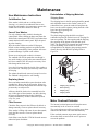
Reinstallation of Shipping Materials
Cold Weather Care
Shipping Brace
If the washer is delivered on a cold day (below
freezing), or is stored in an unheated room or area
during the cold months, do not attempt to operate the
washer until it has had a chance to warm up.
The shipping brace in the lid opening should be saved
and reinstalled whenever the washer is moved. To
reinstall the brace, open the washer lid and place the
brace over the washer agitator, placing the back of the
brace into the lid opening first.
Care of Your Washer
Use only a damp or sudsy cloth for cleaning the
control panel. Some cleaning products may harm the
finish on the control panel. DO NOT use products that
contain alcohol on the control panel. Wipe the panel
dry after cleaning.
Wipe the washer cabinet as needed. If detergent,
bleach or other washing products are spilled on the
cabinet, wipe immediately. Some products will cause
permanent damage if spilled on the cabinet.
Shipping Plug
The plastic shipping plug should be saved and
reinstalled any time the washer is moved. The plug fits
into two openings: The base opening and the shipping
plug opening on the bottom of the movable pivot
dome. The plug MUST be inserted into both openings
to prevent damage to the washer. In order to
accomplish this, the shipping plug opening must be
directly lined up with the base opening. Refer to
Figure 56.
Do not use scouring pads or abrasive cleansers.
The washtub will need no particular care though it
may need rinsing or wiping after some unusual loads
have been washed. This also may be necessary if too
little detergent has been used.
1
Leave the lid open to allow the inside of the washer to
dry out after use. This helps prevent musty odors from
developing.
4
2
The agitator should not be removed except for service.
The washtub is designed to be self cleaning.
Replacing Hoses
3
Hoses and other natural rubber parts deteriorate after
extended use. Hoses may develop cracks, blisters or
material wear from the temperature and constant high
pressure they are subjected to.
All hoses should be checked on a monthly basis for
any visible signs of deterioration. Any hose showing
the signs of deterioration listed above should be
replaced immediately. All hoses should be replaced
every five years.
Filter Screens
Check the filter screens in the fill hoses for debris or
damage annually. Clean or replace them if necessary.
If the washer is filling with water slower than normal,
check the filter screens. Clean or replace them if
necessary.
Order filter screen Part No. F270300 from the nearest
authorized parts distributor.
201932
TLW1945N
TLW1945N
1
2
3
4
Shipping Plug Opening
Base Opening
Shipping Plug
Shipping Brace
Figure 56
Motor Overload Protector
The internal overload protector will stop the motor
automatically in the event of an overload.
The overload protector will reset itself in two or three
minutes and the motor will restart automatically.
If the overload protector stops motor again, remove
the washer from use and call the service person to
correct the problem.
© Copyright, Alliance Laundry Systems LLC – DO NOT COPY or TRANSMIT
33
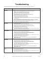
Troubleshooting
Try these troubleshooting tips before making a service call. They may save you time and money.
Washer Symptom
Won’t Fill
Possible Cause/Solution
•
•
•
•
•
•
•
•
•
•
•
•
Make sure lid is closed.
Make sure power cord is plugged all the way into the electrical outlet.
Make sure hot and cold water faucets are turned on.
Make sure that the fill hoses are not kinked or twisted.
Place coin(s) in slide or drop (metered models only).
Push START switch to start the washer (nonmetered models only).
Make sure that the controls are properly set.
Make sure that the last spin has been completed.
Check the laundry room fuse or circuit breaker.
Clean the screens in the water mixing valve and the filter screens located at the faucet end
of the fill hoses.
Water is being siphoned from the washer during the cycle. Refer to the Installation
section to make sure that the drain hose has been properly installed.
The motor overload protector may have stopped the cycle. It will reset itself in two or
three minutes and restart the washer automatically.
Won’t Start
•
•
•
•
•
•
•
Make sure lid is closed.
Place coin(s) in slide or drop (metered models only).
Push START switch to start the washer (nonmetered models only).
Make sure power cord is plugged all the way into the electrical outlet.
Make sure that the controls are properly set.
Check the laundry room fuse or circuit breaker.
The motor overload protector may have stopped the cycle. It will reset itself in two or
three minutes and restart the washer automatically.
Won’t Agitate
•
•
•
•
•
•
Make sure lid is closed.
Place coin(s) in slide or drop (metered models only).
Push START switch to start the washer (nonmetered models only).
Make sure power cord is plugged all the way into the electrical outlet.
Check the laundry room fuse or circuit breaker.
The motor overload protector may have stopped the cycle. It will reset itself in two or
three minutes and restart the washer automatically.
Broken drive belt. Call the service person.
Have a qualified electrician check polarity and grounding. Refer to Electrical
Requirements section.
•
•
Won’t Spin
•
•
•
•
•
•
•
•
Stops/Pauses During
Cycle
•
•
•
34
Make sure lid is closed.
Place coin(s) in slide or drop (metered models only).
Push START switch to start the washer (nonmetered models only).
Make sure power cord is plugged all the way into the electrical outlet.
Check the laundry room fuse or circuit breaker.
The motor overload protector may have stopped the cycle. It will reset itself in two or
three minutes and restart the washer automatically.
Broken drive belt. Call the service person.
Have a qualified electrician check polarity and grounding. Refer to Electrical
Requirements section.
Pauses are part of the washer’s normal operation. The washer will stop (pause) shortly
before the wash and rinse spins.
Check the laundry room fuse or circuit breaker.
The motor overload protector may have stopped the cycle. It will reset itself in two or
three minutes and restart the washer automatically.
© Copyright, Alliance Laundry Systems LLC – DO NOT COPY or TRANSMIT
201932
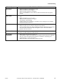
Troubleshooting
Washer Symptom
Possible Cause/Solution
Won’t Drain
•
•
•
•
Make sure drain hose is not kinked or twisted.
Make sure drain hose is not clogged.
Make sure drain receptacle is not clogged.
Refer to the Installation section to make sure that the drain hose has been properly
installed.
Water Leaks
•
Check that fill hoses are properly installed on the faucets and the washer’s water mixing
valve.
Replace the fill hoses every five years.
Make sure drain receptacle is not clogged.
Check laundry room plumbing.
Laundry load may be oversudsing or overloaded. Use less detergent (or low-sudsing
detergent) and proper load sizes.
•
•
•
•
Is Noisy
•
•
•
Wash load may be unbalanced. Open lid and redistribute the load.
Make sure washer is level. Uneven leveling can cause vibration.
A newly installed washer may make a knocking sound if the machine has been in storage.
The belt may have settled. Run washer through 4-5 cycles to loosen belt. Washer
operation will not be affected.
Load is too Wet
•
•
Wash load may be unbalanced. Open lid and redistribute the load.
Load is too small. Add items to make full load.
Wrong Water
Temperature
•
•
Make sure that the controls are properly set.
Check fill hoses. Make sure hot faucet hose is connected to hot mixing valve (indicated
with “H” on the valve bracket) and cold faucet is connected to cold mixing valve
(indicated with “C” on the valve bracket).
Make sure laundry room water heater is adjusted properly.
•
201932
© Copyright, Alliance Laundry Systems LLC – DO NOT COPY or TRANSMIT
35
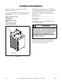
Contact Information
If service is required, contact the nearest Factory
Authorized Service Center.
If you are unable to locate an authorized service center
or are unsatisfied with the service performed on your
unit, contact:
Alliance Laundry Systems
Shepard Street
P.O. Box 990
Ripon, WI 54971-0990
U.S.A.
www.comlaundry.com
Phone: (920) 748-3121
When calling or writing about your unit, PLEASE
GIVE THE MODEL AND SERIAL NUMBERS. The
model and serial numbers are located on the
nameplate. The nameplate will be in the location
shown in Figure 57.
Date Purchased___________________________
Model Number ___________________________
Serial Number ___________________________
Please include a copy of your bill of sale and any
service receipts you have.
WARNING
1
To reduce the risk of serious injury or death,
DO NOT repair or replace any part of the unit
or attempt any servicing unless specifically
recommended in the user-maintenance
instructions or in published user-repair
instructions that you understand and have
the skills to carry out.
W329
If replacement parts are required, contact the source
from where you purchased your washer or call
(920) 748-3950 for the name and address of the
nearest authorized parts distributor.
W138P
W138P
1
Nameplate
Figure 57
36
© Copyright, Alliance Laundry Systems LLC – DO NOT COPY or TRANSMIT
201932
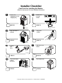
Installer Checklist
Fast Track for Installing the Washer
(Refer to the manual for more detailed information)
• Remove the
Shipping Brace and
Shipping Plug.
CHECK
• Position and
Level the
Washer.
LEVEL
D255I
CHECK
W316IE0A
TLW520N
TLW520N
• Wipe Out Inside of
Washtub.
• Plug In the
Washer.
CHECK
CHECK
D254IE0A
W396IE0A
• Connect
Fill
Hoses.
COLD
• Add Water to the
Washer.
HOT
C
H
TLW1988N
TLW1988N
CHECK
CHECK
• Connect Drain Hose
to Drain
Receptacle.
TLW2056N
TLW2056N
• Check Lid Switch.
W294IE0A
W294IE0A
CHECK
CHECK
© Copyright, Alliance Laundry Systems LLC – DO NOT COPY or TRANSMIT
TLW1974N
TLW1974N