1
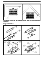
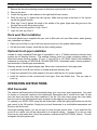
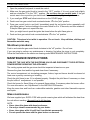
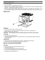
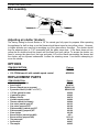
EXCEL-FIRE
VENTED GAS STOVE
INSTRUCTIONS MANUAL
WARNING: If the information in these
instructions is not followed exactly, a fire or
explosion may result causing property
damage, personal injury or loss of life.
FOR YOUR SAFETY: Do not store or use
gasoline or other flammable vapours and
liquids in the vicinity of this or any other
appliance.
Installation and service must be performed
by a qualified installer, service agency or the
gas supplier.
WHAT TO DO IF YOU SMELL GAS:
•
Do not try to light any appliance.
•
Do not touch any electric switch; do not use
any phone in your building.
•
Immediately call your gas supplier from
neighbour’s phone. Follow the gas supplier’s
instructions.
•
If you cannot reach your gas supplier, call the
fire department.
THE INSTALLATION MUST CONFORM WITH LOCAL CODES OR, IN THE ABSENCE OF
LOCAL CODES, WITH THE CURRENT NATIONAL FUEL GAS CODE ANSI Z223.1 (USA)
OR THE CURRENT CAN/CGA B149 INSTALLATION CODES (CANADA).
PLEASE KEEP THIS INSTRUCTIONS MANUAL
FOR FUTURE REFERENCE
mai2000/45052A
EXCEL-FIRE GAS STOVE
1
TABLE OF CONTENTS
GENERAL INFORMATION......................................................................................................................... 2
WARNING................................................................................................................................................... 2
TECHNICAL SPECIFICATIONS................................................................................................................. 3
Burner..................................................................................................................................................... 4
Gas Valve SIT 820 Nova mV ................................................................................................................. 4
Pressure Adjustments ....................................................................................................................... 4
INSTALLATION........................................................................................................................................... 5
Safety notice........................................................................................................................................... 5
Clearances to combustibles ................................................................................................................... 5
Logs installation .......................................................................................................................................... 6
Rock wool fiber installation..................................................................................................................... 7
Optional 6-inch pipe installation ............................................................................................................. 7
OPERATION INSTRUCTIONS ................................................................................................................... 7
Wall thermostat ...................................................................................................................................... 7
Optional blower ...................................................................................................................................... 8
Blower electrical connection .............................................................................................................. 8
Gas connection ...................................................................................................................................... 9
Spill switch.............................................................................................................................................. 9
LIGHTING PROCEDURES......................................................................................................................... 9
Before lighting ........................................................................................................................................ 9
The first fire ............................................................................................................................................ 9
Shutdown procedures .......................................................................................................................... 10
MAINTENANCE INSTRUCTIONS ............................................................................................................ 10
Glass maintenance............................................................................................................................... 10
Glass door ............................................................................................................................................ 11
Removal .......................................................................................................................................... 11
Cleaning .......................................................................................................................................... 11
Installation ....................................................................................................................................... 11
Burner removal and installation............................................................................................................ 11
Removal .......................................................................................................................................... 11
Installation ....................................................................................................................................... 12
Gas pressure adjustments ................................................................................................................... 12
Pilot assembly ...................................................................................................................................... 13
Adjusting air shutter.............................................................................................................................. 13
OPTIONS .................................................................................................................................................. 13
REPLACEMENT PARTS .......................................................................................................................... 13
LIMITED WARRANTY .............................................................................................................................. 14
EXCEL-FIRE GAS STOVE
2
GENERAL INFORMATION
The EXCEL-FIRE gas stove is a high-efficiency free-standing gas appliance with a maximum input
rating of 30 000 BTU/h (8,8 kW) with natural gas or 26 000 BTU/h (7,6 kW) with propane. It
features an adjustable millivolt valve and a constant pilot. This means that you can set the height of
the flame with a control knob. An optional wall thermostat is also available for automatic room
temperature control. The valve is also independent of any exterior electrical supply. Your appliance
will therefore continue to heat your house in the event of a power failure.
To improve efficiency, a 130 CFM (3.68 m3/min) blower with speed control and thermo-switch for
automatic on/off control is available as an option.
Read these instructions and consult local building authorities before installing this appliance. Install
the unit and its venting system only as directed in these instructions.
SAVE THESE INSTRUCTIONS FOR FUTURE REFERENCE
This gas stove has been tested by Intertek Testing Services in accordance with canadian
CSA 2.22/aM99, CGA-2,17-M91 and U.S.A ANSI/Z21.50-a-1999, UL307B-1995 standards.
WARNING
•
•
•
•
•
•
•
•
•
•
Installation should be done by a qualified installer.
Do not burn wood or any other material in this appliance.
Hot when in operation. Keep children, furniture, clothing and flammable material away from the
appliance.
Advise adults and children about the hazard of high surface temperatures and that they should
stay away to avoid burns or clothing ignition.
Young children should be supervised when they are in the same room as the appliance.
The appliance should be inspected before use and at least annually by a qualified service
person. More frequent cleaning may be required due to excessive lint from carpeting, bedding
material, etc.
It is imperative that the control compartments, burners and circulating air passageways be kept
clean.
Do not modify this appliance.
The openings in the gas stove pedestal should never be blocked.
Provide adequate accessibility clearances for servicing and proper operation.
EXCEL-FIRE GAS STOVE
3
TECHNICAL SPECIFICATIONS
Dimensions
• Height :
• Width :
• Depth :
Glass
29 ¾ in.
24 in.
20 in.
756 mm
610 mm
508 mm
18 ½ in.
x 10 ½
470 mm x 267
Weight
140 lbs
64 kg
Colour
metallic black
Flue pipe
"B-Vent" ou "L-Vent"
∅ 4 in.
(100 mm)
Clearance to combustibles
• Back:
4 in.
102 mm
• Side:
8 in.
204 mm
• Corner:
2 in.
50 mm
• Ceiling:
48 in. 1228 mm
• Floor:
Combustible Note 1
in.
mm
Note 1 : Your stove has been successfully certified while installed
on a wood floor. Do not install your stove on carpet. Choose
instead ceramic tile or wood floor.
EXCEL-FIRE GAS STOVE
4
Burner
Maximum Input, BTU/h (kW)
minimum :
maximum :
minimum :
maximum :
minimum :
maximum :
∅:
Inlet Pressure INWC (kPa)
Manifold Pressure INWC (kPa)
Burner orifice
Propane LP
20 000
(5,9)
26 000
(7,6)
11,0
(2,8)
14,0
(3,5)
7,0
(1,8)
10,0
(2,5)
#52 DMS
∅:
#51 DMS
#30 DMS
(in.)
1/4 open
full open
Naturel Gas
Model SIT 0.820.634 Nova
mV
Propane LP
Model SIT 0.820.633 Nova
mV
Injecteur du pilot
Air Shutter opening
Naturel Gas
20 000
(5,9)
30 000
(8,8)
5,0
(1,3)
7,0
(1,8)
1,8
(0,5)
3,5
(0,9)
#36 DMS
Gas Valve SIT 820 Nova mV
Millivolt Gas Valve :
Your stove is equipped with a sophisticated gas control valve, which will give you a safe use of your appliance. The
gas control valve SIT 820 Nova mV operates without electricity due to the energy given by the pilot flame and
captured by the thermo-generator. (also called thermopile). The admission of the gas fuel to the burner is done only
under safe conditions.
Pressure Adjustments
• Adjustments to the valve assembly must be performed by a qualified service person.
• The appliance and its individual shutoff valve must be disconnected from the gas supply piping system during
any pressure testing of that system at test pressures in excess of ½ psi (3.5 kPa);
• The appliance must be isolated from the gas supply piping system by closing its individual manual shutoff valve
during any pressure testing of the gas supply piping system at test pressures equal to or less that ½ psi (3.5
kPa);
NATURAL GAS
The inlet supply or line pressure must be a minimum of 5 INWC and a maximum of 7 INWC. The orifice has a #36
hole.
ELEVATION (Canada)
INPUT RATING
0-4500 ft (0-1400m)
Over 4500 ft (1400 m) +
30 000 BTU/h (8.8 kW)
30 000 BTU/h (8.8 kW) less 4% per 1000 ft (300 m)
or reduce manifold pressure by 0.25 INWC per 1000 ft (300 m)
ELEVATION (USA)
INPUT RATING
0-2000 ft
Over 2000 ft
30 000 BTU/h (8.8 kW)
Refer to local codes
GAZ PROPANE
The inlet supply or line pressure must be a minimum of 10.5” WC and a maximum of 12” WC. The orifice has a #52
hole.
ELEVATION (Canada)
INPUT RATING
0-4500 pi (0-1400 m)
4500 pi (1400m)+
26 000 BTU/h (7.6kW)
26 000 BTU/h (7.6kW) moins 4% par 1000 pi (300m)
or reduce manifold pressure by 1 INWC per 1000 ft
ELEVATION (USA)
INPUT RATING
0-2000 ft
26 000 BTU/h (7.6kW)
Over 2000 ft
Refer to local codes
NOTE : The input rating should always be checked when first running this appliance. To do this, verify inlet valve
pressure and manifold pressure,. Adjust manifold pressure to meet values range as indicated in burner
characteristics table.
EXCEL-FIRE GAS STOVE
5
INSTALLATION
Safety notice
•
•
•
•
•
•
•
•
•
•
•
Improper installation may result in a house fire. Follow installation directions.
Installation must be in accordance with local building codes or, in the absence of local
codes, with current CAN/CGA B 149 installation codes for gas appliances in Canada and
current National Fuel Gas Code ANSI Z223.1 in the USA.
Installation should be done by a qualified installer.
This gas stove must be vented outside.
When installed with optional blower or hand held remote, must be electrically grounded in
accordance with local codes or, in the absence of local codes, with THE NATIONAL
ELECTRICAL CODE, ANSI/NFPA 70, or the CANADIAN ELECTRICAL CODE, CSA C22.1.
Because of high operating temperatures, the EXCEL-FIRE should be located away from
high traffic areas, furniture, curtains, and other combustible material.
Always locate the stove as near as possible to an outside wall to keep horizontal vent length to
a minimum.
Provide adequate accessibility clearances for servicing and proper operation.
Never install the stove in a hallway or near a staircase as it may block the way in case of a fire.
Provide adequate clearances around air openings into the combustion chamber..
If the appliance is being installed on combustible flooring, such as directly on carpeting, tile, or
other combustible material other than wood flooring, the appliance shall be installed on a metal
or wood panel extending the full width and depth of the appliance.
A gas appliance must not be connected to a chimney flue serving a separate solid-fuel
burning appliance.
Now you have decided where to install your stove, you are ready to start the installation
•
Move the EXCEL-FIRE to the desired position. Mark the location for the gas inlet pipe and the
location where the vent pipes will go. Remove the appliance.
•
Route a 3/8" NPT minimum iron pipe gas line to the desired location.
•
Install a shutoff valve to the gas line. Tighten securely using a pipe joint compound
NOTE: The valve includes two ¼” tapings for test gauge connection. You may need, however,
to install a 1/8” plugged tapping between the gas line and the connection point to the stove, if it
is required by local codes.
Clearances to combustibles
Clearance distances between the stove and any combustible material must be maintained while
installing your appliance.
Clearance to the floor is:
0
Clearance to rear wall is:
4” (102 mm)
Clearance to side wall is:
8” (203 mm)
Clearance to wall from corner: 2” (51 mm)
EXCEL-FIRE GAS STOVE
6
For clearance between pipe and flammable materials, follow vent pipe manufacturer’s
instructions.
Logs installation
EXCEL-FIRE GAS STOVE
7
1.
2.
3.
4.
Remove the two door retaining screws at the bottom right and left of the door.
Remove the door.
Locate the log grate in the retainers in the right and left rear corners.
Place the rear log (1) against the rear log stop. Make sure grooves at the back of the log line
up with the grates log stop.
5. Place logs 2 and 3 against the stops in the middle of the grate. Again see that grooves in the
the logs line up with the grates log stop.
6. Place log 4 into the grooves of logs 1 and 2.
7. Log 5 sits over log 4 and 3.
Rock wool fiber installation
One small plastic bag is supplied with your unit its filled with rock wool fiber which, when glowing
red, resembles hot embers.
• Place rock wool fiber on top of the front gas ports and up to the grates middle section.
• Put the door back in place. Install the two door retaing screws.
Optional 6-inch pipe installation
Instead of using a standard B-vent pipe it is possible to use a 4" flexible aluminum chimney lining
system into an existing chimney. The existing chimney must be a code complying masonry or
listed fuel burning chimney system: ‘B’ vent, ‘L’ vent UL103 or ULC S629. Refer to the installation
standards in your area or CAN/CGA B-149 AND ANSI Z223-1 standards (under "venting systems")
and instruction of flexible pipe manufacturer.
Warning: always use an approved gas pipe. Never use a conventional 6-inch pipe alone.
• Install the first 4-inch B-vent section or flexible aluminum chimney liner.
• Fasten the optional 6-inch collar adapter to the stove with the two (2) screws supplied.
• Install the sections of the conventional 6-inch pipe. Over the flexible liner. That you want to
cover up.
OPERATION INSTRUCTIONS
Wall thermostat
The optional wall thermostat will automatically keep your room at an even temperature. You need
to choose a convenient location for the thermostat. Remember that it should be at least 10 feet
from the stove and away from direct radiation of the fire. Run the correct gauge wire (see table)
from the valve to the thermostat and wire as shown in the diagram.(on next page)
To operate your EXCEL-FIRE using the wall thermostat, follow the lighting procedure and set the
gas control to the ON position. Simply set your wall thermostat to a comfortable temperature and
the stove will do the rest.
During the heating season, you do not have to touch the gas control valve. If you would like the
stove off for a while, just set the thermostat to its minimum setting. However if you do not need
the stove for quite some time, follow the procedure outlined in the SHUTDOWN section. This will
extinguish the pilot light as well.
EXCEL-FIRE GAS STOVE
8
DISTANCE DIAMETRE
20 pi
18GA
30 pi
16GA
40 pi
14 GA
50pi
12GA
REMOVE THE BLUE JUMPER BETWEEN TP & TPTH SCREWS ON THE GAS VALVE.
Optional blower
The blower control contains a variable speed switch and a thermal switch. When the stove is
operating, the thermal switch will turn on at 110° F, allowing the blower to operate. When the stove
cools to 90° F, the thermal switch turns off the blower in about 40 minutes. This prevents the
blower from operating when the stove is not in use.
The blower not only helps circulate air throughout the room, it also increases the heat output and
efficiency of the EXCEL-FIRE.
Blower electrical connection
Install the blower to the back of the stove using the 4 mounting screws. Than connect the two wires
to the motors connectors.
If you wish to make a direct electrical connection to the blower without using the six-foot cord
supplied, route a 120 volt, 60 Hz electrical power supply line to the same location. Remove the
power cord and connect the 120V line as per the following procedure:
•
•
•
•
•
•
Unscrew the speed control unit and pull a few inches away from the junction box
Unscrew the two marr connectors attached to the cord (P) and the cord ground
Remove the cord and route the supply line through the same holes
Make the electrical connection with the same wires the cord was attached to
Screw the ground wire to the junction box (G)
Screw the speed control unit back in place
CONNECT THE POWER LINE TO THE SAME
WIRES THE CORD WAS CONNECTED TO (P)
P
G
P
JUNCTION BOX
SPEED CONTROL
NOTE: If you prefer to use the six-foot cord supplied by Drolet, just connect it to a 120V outlet.
EXCEL-FIRE GAS STOVE
9
Gas connection
• Move the EXCEL-FIRE to the desired
position and secure in place with four screws.
• Connect gas line to the stove using listed
connectors
• Check the gas line piping for leaks. Use a
soap and water solution.
WARNING: DO NOT USE OPEN FLAME TO
CHECK LEAKS.
Spill switch
The EXCEL-FIRE is fitted with a spill switch. This switch is designed to shut down the unit if the
flue system is not venting properly. This is usually due to negative pressure in the home or a bird's
nest in the flue. If the unit shuts down by itself without apparent reason, the spill switch may be
telling you the unit is not venting properly. Consult your service technician.
LIGHTING PROCEDURES
Before lighting
1. Do not use this appliance if any part has been under water. Immediately call a qualified service
technician to inspect the appliance and to replace any part of the control system and any gas
control which has been under water.
2. Make sure that there are no obstructions in the air intake or venting system.
3. Clear the immediate area of combustible materials, gasoline, and other flammable liquids and
vapours.
4. Make sure that the gas log is in its proper place.
5. Remove plastic film on brass trims
The first fire
During the first few hours of operation the appliance will release an odor. This is caused by the
burning off of residual oils used in the manufacturing process and by the curing of the high heat
paint. The ceramic glass window may require cleaning after this initial "burn in." Please read the
instructions on cleaning in the MAINTENANCE section before doing so.
WARNING: If you do not follow these lighting instructions exactly, a fire or explosion may
result causing property damage, personal injury, or loss of life.
EXCEL-FIRE GAS STOVE
10
1. Open the pedestal front panel to reach the control.
2. Make sure the gas control knob is turned to the ‘’OFF’’ position. If it is not, press knob slightly
and turn clockwise 3 to the "OFF’’ position. Do not force the gas control knob. If the gas
control was in the on position you should wait 5 minutes before trying to re-light the stove.
3. If you smell gas STOP and follow instructions on the COVER page.
4. Push in and turn gas control knob counterclockwise 4 to the "pilot" position.
5. Press gas control knob in and hold. Immediately push the red igniter button repeatedly until
pilot flame ignites. Continue holding in the control knob for 5 to 10 seconds, and then release it.
If the pilot flame goes out, repeat this step.
Note: you might have to push the igniter few times before the pilot flame gets on
6. Push and turn gas control knob counterclockwise 4 to the "on" position.
CAUTION: This stove is hot while in operation. Do not touch. Keep children, clothing and
flammable materials away.
Shutdown procedures
Push in and rotate the gas control knob clockwise to the "off" position. Do not force.
If you are going to perform any maintenance or cleaning, first allow the stove to cool completely.
Follow the instructions in the section on cleaning under MAINTENANCE INSTRUCTIONS.
MAINTENANCE INSTRUCTIONS
TURN OFF THE GAS WITH THE SHUTDOWN VALVE AND DISCONNECT THE ELECTRICAL
POWER BEFORE SERVICING THE APPLIANCE.
The venting system and the gas stove should be inspected at least once a year.
Remove the glass front and the logs and clean them if necessary.
The control compartment, air circulating passages, firebox, logs and burner should be cleaned at
least once a year by vacuuming or brushing.
Check the pilot flame to see if it is adjusted properly. Readjust the pilot flame if necessary or clean
the pilot orifice if readjustment is not possible.
Check the burner for flame lifting or for unusual flame pattern. If necessary clean the burner orifice.
For more information, see “Adjustments” in the INSTALLATION section.
Keep the area clear and free from combustible materials, gasoline and other flammable vapours
and liquids.
Glass maintenance
We have supplied your EXCEL-FIRE with special ceramic glass which will withstand the heat from
the unit without cracking. Be careful not to hit the glass.
NOTE:
• Never clean this glass with abrasive cleaners.
• Use only a cleaner recommended by your dealer.
• Never clean glass while it is still hot. It could stain permanently.
• Do not operate the stove with the glass broken or removed
EXCEL-FIRE GAS STOVE
11
If Your Glass Breaks:
• See your dealer for exact replacement glass.
• Remove front as explained above. With a 5/16” nut driver remove all nuts holding the glass
retainers. Carefully remove retainers and seal.
• After removing all broken glass pieces, insert new glass and reinstall seal and brackets. It the
seal is damaged, replace it with an identical new seal from your dealer (see replacement parts)
Glass door
Removal
• Let the stove cool down for at least one hour.
• Remove the two (2) screws on the left and right, at the bottom of the glass front.
• Remove the glass front assembly.
CAUTION: Do not operate your stove without a glass front or with a broken glass.
Cleaning
• Only clean the glass when cold.
• Clean with liquid type cleaners or soap and water; do not use abrasive cleaners, which can
scratch the glass.
Installation
• Place the glass front assembly back in position. Align the holes for screws.
• Install the two (2) screws below the ashtray down the door.
Burner removal and installation
Removal
•
•
•
•
•
Remove the glass front assembly as shown above.
Carrefully remove logs
Lift out the grate and hearth insert around burner.
Unscrew the retaining screws on each side of the burner.
Slide burner to the left and lift out.
EXCEL-FIRE GAS STOVE
12
Installation
•
Put the burner assembly back in the fire box
and push to the right.
•
Make sure the main orifice is inserted in the
ventury tube as shown. And screw the burner
back into place.
WARNING: Never operate the gas stove
without having the orifice properly inserted
in the venturi tube. This could result in
serious damage to the gas insert and is a
serious risk of fire.
Gas pressure adjustments
NOTE: Adjustments to the valve assembly must be performed by a qualified service person.
• The appliance and its individual shutoff valve must be disconnected from the gas supply piping
system during any pressure testing of that system at test pressures in excess of ½ psi (3.5 kPa).
• The appliance must be isolated from the gas supply piping system by closing its individual
manual shutoff valve during any pressure testing of the gas supply piping system at test
pressures equal to or less that ½ psi (3.5 kPa).
The maximum manifold pressure is set at the factory at 3.5” WC for natural gas and 10” WC for
propane. To adjust the maximum manifold pressure for altitude, the variable gas control knob must
then be removed using a special screwdriver. Rotate and reinstall the knob so that the maximum
pressure reading is correct.
Locate the two pressure test taps. Check line pressure or manifold pressure by loosening the
small screw inside the tap with a flat-head screwdriver about one turn. Connect pressure gauge
using a ¼” I. D. rubber hose.
Ensure the line pressure falls within the allowable limits and adjust the manifold pressure according
to the elevation table.
The pilot should have a strong blue flame, which engulfs the thermopile and the thermocouple. If
there is any yellow in the pilot flame tips, the gas flow must be reduced by adjusting the pilot
pressure adjustment screw.
Remember to replace all adjustment screws in the original position to avoid any gas leaks.
EXCEL-FIRE GAS STOVE
13
Pilot assembly
Adjusting air shutter (Venturi)
The factory setting for the air shutter is 1/4” for natural gas, fuily open for propane. After operating
the appliance for half an hour or so the flames should have turned a nice yellow colour. However,
in higher altitudes you may find a smudging up of the glass after a few days. The shutter should
then be adjusted open in 1/16” increments until the glass stays clear. If the flame does not turn
yellow the air shutter should be closed until the flame just turns yellow. To access the shutter you
need to remove the glass front, the logs and grate. Lift out the hearth surrounding the burner and
the shutter will be exposed underneath. Loosen the retaining screw 1 turn before attempting to
move the shutter.
OPTIONS
ITEM DESCRIPTION
• Wall thermostat kit
• 130 CFM blower kit with variable speed control
Part no
AC05558
AC05914
REPLACEMENT PARTS
ITEM DESCRIPTION
• 6’’ stove pipe adapter
• Set of logs 5
• Burner (natural gas or propane)
• Pyroceram Glass (19.446" x 11.737")
• 1/2″ dia. gasket for door
• U gasket for glass
• Blower 130 cfm
• Variable speed control
• Thermo-switch (for blower)
• Gas valve (natural gas) SIT
• Gas valve (propane) SIT
• Pilot assembly (natural gas) SIT
• Pilot assembly (propane) SIT
• Piezo igniter
• Burner orifice (natural gas #36)
• Burner orifice (propane #52)
• Thermocouple
• Spill switch
• Thermopile
Part no
SE9348
AC05791
SE09311-01
SE09335-05
40020
40005
44070
44080
44044
49133
49126
49103
49106
49128
9071
9071-01
49122
44047
49095
EXCEL-FIRE GAS STOVE
14
1700, rue Léon-Harmel, Québec (Québec) G1N 4R9
tel. : (418) 527-3060 fax : (418) 527-4311
e-mail : [email protected] web site : drolet .ca
LIMITED WARRANTY
The warranty of the manufacturer extends only to the original consumer purchaser and is not transferable. This warranty covers
brand new products only, which have not been altered, modified nor repaired since shipment from factory. Proof of purchase (dated
bill of sale), model name and serial number must be supplied when making any warranty claim to your Drolet dealer
This warranty applies to normal residential use only. Damages caused by misuse, abuse, improper installation, lack of
maintenance, over firing, negligence or accident during transportation are not covered by this warranty.
This warranty does not cover any scratch, corrosion or discoloration caused by over firing, abrasives or chemical cleaners. Any
defect or damage caused by the use of unauthorized parts or others than original parts void this warranty.
An authorized qualified technician must perform the installation in accordance with the Instructions supplied with this product and all
local and national building codes. Any service call related to an improper installation is not covered by this warranty.
Returned products are to be shipped prepaid to the manufacturer for investigation. If a product is found to be defective, The
manufacturer will repair or replace such defect and reasonable transportation fees will be refund. Repair work covered by the
warranty, executed at the purchaser domicile by an authorized qualified technician requires the prior approval of the manufacturer.
Labour cost and repair work to the account of the manufacturer are based on predetermined rate schedule and must not exceed the
wholesale price of the replacement part.
The manufacturer at its discretion may decide to repair or replace any part or unit after inspection and investigation of the defect.
The manufacturer may, at its discretion, fully discharge all obligations with respect to this warranty by refunding the wholesale price
of any warranted but defective parts
The manufacturer shall in no event be responsible for any special, indirect, consequential damages of any nature, which are in
excess of the original purchase price of the product.
WARRANTY APPLICATION
DESCRIPTION
PARTS
LABOUR
Combustion chamber (weldings only)
5 years
5 years
Stainless baffle
5 years
1 year
Carbon Steel baffle
2 years
1 year
Gas Valve, piezo, thermopile, thermoswitch, burner
1 year
1 year
N/A
N/A
Ceramic glass (thermal breakage only)
5 years
N/A
Paint, gasket, blower, Blower thermoswitch and rheostat
1 year
N/A
Gold plating (tarnishing)
5 years
N/A
Logs
Shall your unit or a components be defective, contact immediately your Drolet dealer. Prior to your call make sure you have the
following information necessary to your warranty claim treatment:
•
•
You name, address and telephone number;
Bill of sale, dealer’s name;
•
•
Serial number and model name as indicated on the
nameplate fixed to the back of your unit;
Nature of the defect and any relevant information.
Before shipping your unit or defective component to our plant, you must obtain from your Drolet dealer an Authorization
Number. Any merchandise shipped to our plant without authorization will be refused automatically and returned to sender.