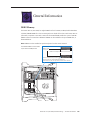
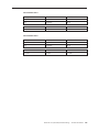
1
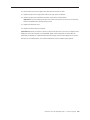
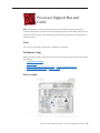
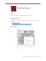
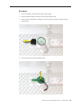
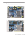
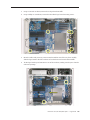
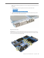
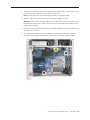
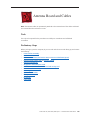
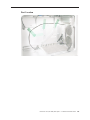
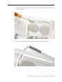
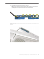
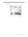
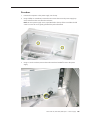
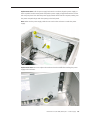
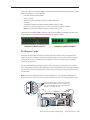
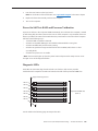
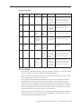
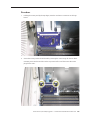
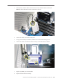
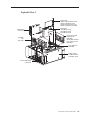
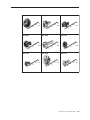
18. Using a 3 mm flathead hex driver, replace the six long processor mounting screws. 19. Using a 3 mm flathead hex driver, tighten the four captive float plate screws. Power Mac G5 (Late 2005) Take Apart — Processor (Quad) 101 20. Reconnect the processor support bar cable with the processor cable. 21. Replace the processor support bar cable in the clip on the PCI divider. 22. Replace the processor inlet frame assembly on the front of the heatsink. Important: If you are replacing the processor with a new processor, be sure to use the inlet frame included with the replacement processor. 23. Replace the heatsink cover. 24. Replace the front inlet fan assembly. Important: Whenever you replace a processor with a new processor, you must run Apple Service Diagnostic (once the computer is reassembled). Apple Service Diagnostic for Power Mac G5 (Late 2005) is available as a download from the Disc Images section of the Apple Service Source website. For more information, see “Thermal Calibration” in the Troubleshooting chapter. Power Mac G5 (Late 2005) Take Apart — Processor (Quad) 102 Processor Support Bar and Cable Note: The illustrations in this procedure are based on the Power Mac G5 (Late 2005 Quad) computer. Although the Power Mac G5 (Late 2005 Dual) support bar cable differs from the Quad cable (it has two connectors rather than three), the take-apart procedure for all configurations is primarily the same. Tools The only tool required for this procedure is a Phillips #1 screwdriver. Preliminary Steps Before you begin, open the computer, lay it on its side with the access side facing up, and remove the following: • Front inlet fan assembly • Heatsink cover • Processor inlet frame (Dual 2.0/2.3 GHz) or Processor inlet frame (Quad) • Processor (Dual 2.0/2.3 GHz) or Processor (Quad) Part Location Power Mac G5 Take Apart (Late 2005) — Processor Support Bar and Cable 103 Procedure 1. Remove the two mounting screws from the processor support bar. 2. Disconnect the processor support bar cable from the logic board. 3. Power Mac G5 (Late 2005 Quad): If necessary, remove the processor support bar cable from the clip on the PCI divider. 4. Lift the bar and attached cable straight up and out of the enclosure. Power Mac G5 Take Apart (Late 2005) — Processor Support Bar and Cable 104 To remove the cable from the support bar: 1. Depress the two clips on either side of the front inlet fan connector and remove the connector from the support bar. 2. Unclip the cable from the support bar and remove the cable from the bar. Power Mac G5 Take Apart (Late 2005) — Processor Support Bar and Cable 105 Front Panel Board Tools The only tool required for this procedure is a Phillips #1 screwdriver. Preliminary Steps Before you begin, open the computer, lay it on its side with the access side facing up, and remove the following: • Front inlet fan assembly • Any memory DIMMs installed next to the front panel board Part Location Power Mac G5 (Late 2005) Take Apart — Front Panel Board 106 Procedure 1. Disconnect the power button cable from the front panel board. 2. Remove the two front panel board mounting screws. 3. Gently pull the board back from the front panel, tip the back of the board up so that it clears the DIMM slot ejectors, and remove the board from the enclosure. Power Mac G5 (Late 2005) Take Apart — Front Panel Board 107 Note: If you are replacing the front panel board with a new board, carefully remove the EMI shield from the original board and transfer it to the replacement board. Make sure that the fingers of the shield enclose the board as shown in the illustration below. Replacement Note: When replacing the front panel board, align the ports on the board with the openings in the front panel board. Then press the board firmly to the enclosure. Power Mac G5 (Late 2005) Take Apart — Front Panel Board 108 Power Button Tools The only tool required for this procedure is a jeweler’s flat-blade screwdriver. Preliminary Steps Before you begin, open the computer, lay it on its side with the access side facing up, and remove the following: • Front inlet fan assembly • Any memory DIMMs installed next to the front panel board • Front panel board Part Location Power Mac G5 (Late 2005) Take Apart — Power Button 109 Procedure 1. Lay the computer so that the front panel is facing down. 2. Remove the black rubber cap that covers the power button LED. 3. Using a jeweler’s flat-blade screwdriver, pry up the metal C-ring that secures the power button board. 4. Lift up and remove the power button board. Power Mac G5 (Late 2005) Take Apart — Power Button 110 5. Remove the metal activation ring that lies below the power button board. 6. Remove the power button from the enclosure. Power Mac G5 (Late 2005) Take Apart — Power Button 111 Logic Board Tools The following tools are required for this procedure: • Phillips #1 screwdriver • long-handled T-10 torx driver • 9/32-inch nut driver Preliminary Steps Before you begin, open the computer, lay it on its side with the access side facing up, and remove the following: • Front inlet fan assembly • Heatsink cover • Processor inlet frame (Dual 2.0/2.3 GHz) or Processor inlet frame (Quad) • Processor (Dual 2.0/2.3 GHz) or Processor (Quad) • Processor support bar • All graphics and PCI Express cards • AirPort Extreme/Bluetooth combo card and runway card • Rear exhaust fan assembly • PCI card guide • Speaker/fan assembly • Front panel board • PCI divider Power Mac G5 (Late 2005) Take Apart — Logic Board 112 Part Location Power Mac G5 (Late 2005) Take Apart — Logic Board 113 Procedure 1. Disconnect the cables from the top and bottom edge of the logic board. 2. Using a long-handled T-10 torx driver, remove the nine power supply bus bar screws. Power Mac G5 (Late 2005) Take Apart — Logic Board 114 3. Using a 9/32-inch nut driver, remove the six logic board standoffs. 4. Using a Phillips #1 screwdriver, remove the three black logic board mounting screws. 5. Move the cables and processor power terminal assemblies out of the way. Then carefully slide the logic board to the left to release it from the three mushroom-head standoffs. 6. Tilt the logic board up and maneuver it out of the enclosure, making sure the ports clear the enclosure openings. Power Mac G5 (Late 2005) Take Apart — Logic Board 115 Note: Perform the following procedures only if you are replacing the logic board with a new logic board. 7. Transfer the following from the original logic board to the replacement board: • Memory DIMMs • Ambient board • Quadro FX 4500 graphics card cable (if installed) 8. Transfer the port EMI shield from the original logic board to the replacement logic board, making sure the shield is fully seated on the ports. Replacement Procedure Important: Before you install a replacement logic board, remove the protective clips and caps circled in the illustration below and transfer them to the logic board you are returning to Apple. Do not remove the mylar sheet from the board. Power Mac G5 (Late 2005) Take Apart — Logic Board 116 1. Temporarily tuck the top cables into the openings in the media shelf so that they are out of the way. Also tape or hold the bottom cables out of the way. Note: You may find a long strip of packing tape useful in securing the cables. 2. Angle the logic board into the enclosure so that the port edge goes in first. Warning: Be careful not to catch the battery on the edge of the case as you lower the logic board into the enclosure. Also make sure the connector ends of the antenna cables are not caught under the board. 3. Position the logic board on the three mushroom-head standoffs, aligning the ports with the openings in the enclosure. 4. Slide the board toward the rear of the computer so that the logic board locks onto the mushroom-head standoffs and the ports are fully seated in the back panel openings. Power Mac G5 (Late 2005) Take Apart — Logic Board 117 5. Replace the three logic board screws and six standoffs in the order indicated below. Important: There are two versions of the power supply, one with two processor power terminal assemblies and the other with just one processor power terminal assembly. In either case, make sure the rear standoffs are threaded through the power terminal rings before you insert the standoffs into the logic board. Power Mac G5 (Late 2005) Take Apart — Logic Board 118 6. Replace the nine power supply bus bar screws. 7. Reconnect all cables at the top and bottom edge of the logic board. 8. Replace the PCI divider. 9. Replace the front panel board. 10. Replace the speaker/fan assembly and reconnect its cables to the logic board. 11. Replace the PCI card guide. Note: If the computer includes a Quadro FX 4500 graphics card, you must connect the Quadro FX 4500 cable to the logic board before you replace the PCI card guide. 12. Replace the rear exhaust fan assembly and reconnect its cable to the logic board. 13. Replace the runway and AirPort Extreme/Bluetooth combo cards. 14. Replace all graphics and PCI Express cards. 15. Replace the processor support bar and reconnect the processor support bar cable to the logic board. 16. Replace the processor. 17. Replace the processor inlet frame. 18. Replace the heatsink cover. 19. Replace the front inlet fan assembly. Important: Whenever you replace a logic board with a new logic board, you must run Apple Service Diagnostic (once the computer is reassembled). Apple Service Diagnostic for Power Mac G5 is available as a download from the Disc Images section of the Apple Service Source website. For more information, see “Thermal Calibration” in the Troubleshooting chapter. Power Mac G5 (Late 2005) Take Apart — Logic Board 119 Antenna Board and Cables Note: The antenna cables are permanently attached to the antenna board. The cables and board are removed from the enclosure as a unit. Tools The only tools required for this procedure are a Phillips #1 screwdriver and a flatblade screwdriver. Preliminary Steps Before you begin, open the computer, lay it on its side with the access side facing up, and remove the following: • Front inlet fan assembly • Heatsink cover • Processor inlet frame (Dual 2.0/2.3 GHz) or Processor inlet frame (Quad) • Processor (Dual 2.0/2.3 GHz) or Processor (Quad) • Processor support bar • All graphics and PCI Express cards • AirPort Extreme/Bluetooth combo card and runway card • Rear exhaust fan assembly • PCI card guide • Speaker/fan assembly • Front panel board • PCI divider • Logic board Power Mac G5 (Late 2005) Take Apart — Antenna Board and Cables 120 Part Location Power Mac G5 (Late 2005) Take Apart — Antenna Board and Cables 121 Procedure 1. Remove the antenna cables from the tape on the inside of the enclosure’s side panel and from the channel between the PCI cage and the rear exhaust openings on the inside of the enclosure’s back panel. 2. Remove the three screws on the interior antenna board cover. Note: This procedure will also release the exterior antenna board cover on the back panel. Power Mac G5 (Late 2005) Take Apart — Antenna Board and Cables 122 3. Using a flatblade screwdriver, pry up the interior antenna board cover and remove the cover from the enclosure. 4. Remove the antenna board from the slot in the exterior antenna board cover. Power Mac G5 (Late 2005) Take Apart — Antenna Board and Cables 123 5. Remove the antenna board and cables from the enclosure. Note: If you are replacing the antenna board/cables with a new board/cables, transfer the grounding clip from the original antenna board to the replacement board. Replacement Note: Insert the antenna board into the slot in the exterior antenna board cover as illustrated. Power Mac G5 (Late 2005) Take Apart — Antenna Board and Cables 124 Replacement Note: Be sure to reroute the antenna cables in the channel between the PCI cage and the rear exhaust openings on the inside of the enclosure’s back panel. Power Mac G5 (Late 2005) Take Apart — Antenna Board and Cables 125 Power Supply Tools The only tools required for this procedure are a Phillips #1 screwdriver and 1/4-inch nut driver. Preliminary Steps Before you begin, open the computer, lay it on its side with the access side facing up, and remove the following: • Front inlet fan assembly • Heatsink cover • Processor inlet frame (Dual 2.0/2.3 GHz) or Processor inlet frame (Quad) • Processor (Dual 2.0/2.3 GHz) or Processor (Quad) • Processor support bar • All graphics and PCI Express cards • AirPort Extreme/Bluetooth combo card and runway card • Rear exhaust fan assembly • PCI card guide • Speaker/fan assembly • Front panel board • PCI divider • Logic board Power Mac G5 (Late 2005) Take Apart — Power Supply 126 Part Location Power Mac G5 (Late 2005) Take Apart — Power Supply 127 Procedure 1. Position the computer so the power supply is at the top. 2. Using a Phillips #1 screwdriver, remove the two screws that secure the power supply top cover, and remove the cover from the enclosure. Note: On some power supply covers, a pad attached to the top of the cover hides the left screw. To access this screw, gently peel back the pad as illustrated. 3. Using a 1/4 inch nut driver, remove the mushroom-head standoff closest to the power supply. Power Mac G5 (Late 2005) Take Apart — Power Supply 128 4. Using the Phillips screwdriver, remove the four power supply mounting screws on the bottom of the enclosure. 5. Lift up the bus bar tabs to release them from the plastic runner on the enclosure. Power Mac G5 (Late 2005) Take Apart — Power Supply 129 6. Slide the power supply toward the front of the computer. 7. Tilt the bus-bar-tab edge of the power supply a short distance out of the bottom of the enclosure. (Make sure that the bus bar tabs are released from the plastic runner on the enclosure.) 8. Rotate the power supply up and remove it from the enclosure. Replacement Note: Make sure the plastic trim ring is in place in the power receptacle before replacing the power supply in the enclosure. Power Mac G5 (Late 2005) Take Apart — Power Supply 130 Replacement Note: To fit the power supply back into the enclosure, align the power supply so that it is parallel to the bottom panel and push the power supply straight back until the bus bar tabs snap into place. Then slide the power supply toward the back of the computer, making sure the power receptacle aligns with the opening in the back panel. Note: Make sure the power supply cables do not catch on the enclosure or under the power supply. Replacement Note: Be sure to replace the mushroom-head standoff after installing the power supply in the enclosure. Power Mac G5 (Late 2005) Take Apart — Power Supply 131 Air Deflector Sensor Board Tools The only tool required for this procedure is a flatblade screwdriver. A small mirror to use in locating the board is optional. Preliminary Steps Before you begin, open the computer, lay it on its side with the access side facing up, and remove the following: • Front inlet fan assembly • Heatsink cover • Processor inlet frame (Dual 2.0/2.3 GHz) or Processor inlet frame (Quad) • Processor (Dual 2.0/2.3 GHz) or Processor (Quad) • Processor support bar • All graphics and PCI Express cards • AirPort Extreme/Bluetooth combo card and runway card • Rear exhaust fan assembly • PCI card guide • Speaker/fan assembly • Front panel board • PCI divider • Logic board • Power supply Power Mac G5 (Late 2005) Take Apart — Air Deflector Sensor Board 132 Part Location Power Mac G5 (Late 2005) Take Apart — Air Deflector Sensor Board 133 Procedure 1. Locate the air deflector sensor board inside the enclosure on the bottom right front corner of the frame. You may find a small mirror useful in seeing the board. 2. Disconnect the sensor cable from the air deflector sensor board. 3. Pry up the sensor board from the frame and remove the board from the enclosure. Note: Adhesive on the back of the board attaches the sensor board to the frame. Power Mac G5 (Late 2005) Take Apart — Air Deflector Sensor Board 134 Service Source Troubleshooting Power Mac G5 (Late 2005) © 2005 Apple Computer, Inc. All rights reserved. General Information DDR2 Memory The Power Mac G5 (Late 2005) has eight DIMM slots for PC2 4200, 533 MHz, Double-Data-Rate 2 (DDR2) SDRAM DIMMs. The slots are arranged in two banks of four slots each. Power Mac G5 (Late 2005) computers come with a minimum of 512 MB of RAM, installed as a pair of 256 MB DIMMs in the two center slots. Additional DIMMs can be installed in the open DIMM slots, as illustrated below. Note: DIMMs must be installed in equal-sized pairs from the center outward. The SDRAM DIMMs must be installed in pairs with one DIMM per bank. Install additional DIMMs in these two slots first. DIMMs are already installed in these two slots. If slots are available, and you want to install more memory, install additional DIMMs in a similar fashion: In pairs, one per bank, from the center outward. Bank 2 Bank 1 Power Mac G5 (Late 2005) Troubleshooting — General Information 136 In the Power Mac G5 (Late 2005), DIMMs must fit the following specifications. Memory from older Macintosh computers is not compatible. PC2 4200, 533 MHz, DDR2 DIMMs • 240-pin module • Maximum number of memory devices on DDR2 SDRAM: 18 • Nonparity • Unbuffered (registered or buffered DDR2 SDRAM cannot be used) • Either error-correcting code (ECC) or no error-correcting code (NECC) modules • Note: Do not mix ECC and NECC memory modules within a pair. To identify ECC and NECC DIMMs, check the chip side of the DIMM. ECC DIMMs include an extra memory device as marked below. NECC DIMMs do not have this device. DDR2 Memory Module with ECC DDR2 Memory Module with NECC PCI Express Cards Power Mac G5 (Late 2005) computers have four expansion card slots that accommodate PCI Express cards. The computers come with a high-performance 16-lane (16x) PCI Express graphics card installed in slot 1. The card contains the graphics processor unit (GPU) and provides the computers’ display ports. You can install additional PCI Express cards in slots 2–4. Install a second card in slot 3, a third in slot 4, and a fourth in slot 2 to take advantage of the bus bandwidth of each slot. Before installing a card, however, check the specifications to make sure it can operate correctly in the Power Mac G5 (Late 2005). Note: When certain high-end video cards are installed in slot 1, they block the adjacent PCI Express slot (slot 2). As a result, you can install PCI Express cards in slots 3 and 4 but not in slot 2. The maximum bus width for each PCI Express slot is marked on the card guide. Slot 4 is a 4-lane (4x) slot, slot 3 is an 8-lane (8x) slot, slot 2 is a 4-lane (4x) slot, and slot 1 is a 16-lane (16x) slot. Power Mac G5 (Late 2005) Troubleshooting — General Information 137 Important: Combined maximum power consumption for all four expansion slots should not exceed 200 W. Combined maximum video RAM for all graphics cards is 1 GB. While all slots can accommodate PCI Express cards that have up to 16-lanes, if you install a card that requires a greater bandwidth than the slot provides, the card will operate at the bandwidth of the slot. For example, an 8x card installed in a 4x slot will operate as a 4x card. Refer to the following table for details. PCI Express Slot Bus Bandwith (x) Connector (Lane) 4 4x 16 lane 3 8x 16 lane 2 4x 16 lane 1 16x 16 lane Thermal Calibration To ensure proper fan and temperature control in the Power Mac G5 (Late 2005), you must run Apple Service Diagnostic whenever you replace a processor or logic board with a new processor or logic board. Apple Service Diagnostic for Power Mac G5 is available as a download from http:// www.info.apple.com/discimages/. Note: The calibration process of Apple Service Diagnostic requires a controlled environment to ensure accurate ambient temperature readings. Computers under test must have the transparent air deflector installed and the door sensor switch must be operable. Units under test should also be located away from heating and air conditioning systems and fan exhaust of other machines. Ambient temperature should not go above 77 degrees Fahrenheit or 25 degrees Centigrade. Resetting the Logic Board Some system problems can be resolved by resetting the System Management Unit (SMU) microcontroller chip on the Power Mac G5 (Late 2005) logic board. To reset the logic board, do the following: 1. Shut down the computer. 2. Unplug the computer from its power source. 3. Wait two minutes. 4. Plug the power cord back in, and turn the computer on. If the computer does not power on, there is something else wrong with it; refer to the “Startup Failures” section of “Symptom Charts” in this chapter. You can also reset the logic board by pressing the SMU reset button on the logic board: 1. Shut down the computer. 2. Open the computer, lay it on its side with the access side facing up, and remove the front inlet fan assembly. Power Mac G5 (Late 2005) Troubleshooting — General Information 138 3. Press the reset button on the logic board. Note: For the location of the reset button, see “Logic Board Diagram” in the Views chapter. 4. Replace the front inlet assembly and close the computer. 5. Turn on the computer. Power-On Self Test: RAM and Processor Verification A power-on self test in the computer’s ROM automatically runs whenever the computer is started up after being fully shut down (the test does not run if the computer is only restarted). If the test detects a problem, the status LED located above the power button on the front of the computer will flash in the following ways*: • 1 Flash: No RAM is installed or detected. • 2 Flashes: Incompatible RAM types are installed or RAM installed in wrong slots. • 3 Flashes: No RAM banks passed memory testing. • 4 Flashes: No good boot images are detected in the boot ROM (and/or there is a bad sys config block). • 5 Flashes: The processor is not usable. * Note: The status LED lights up when the power button is depressed at startup. Do not count this light as one of the diagnostic flashes. Diagnostic LEDs Power Mac G5 (Late 2005) logic boards include a set of LEDs to help service providers troubleshoot the computers. The LEDs are located to the left of the top bank of DIMM slots. Edge of main logic board LED #1 LED #2 LED #3 LED #4 Top bank of DIMM slots (Bank 1) LED #5 LED #6 LED #7 Use the table on the following page to interpret the LEDs. Power Mac G5 (Late 2005) Troubleshooting — General Information 139 Diagnostic LED Table LED No 1 Description Color When Expected On Condition CPU A Red Off No 2 Overtemp LED Red No 3 Power On Red No 4 Trickle Power Yellow No 5 Open Firmware Good Green No 6 CPU B Red No 7 Checkstop Red LED “On” Indicates CPU A improperly installed Things to Check Is processor assembly seated properly? Check that mounting screws are properly tightened. Off CPU has Check that space gone is allowed for fans overtemp to ventilate. Verify fans and sensors are connected. On (with air Main power Check connections deflector OK and to the power bus open) within bar. regulation On (with unit AC power Check for AC plugged into OK power at the wall AC power and outlet; try another air deflector outlet. open) On (with air CPU arrived Reset SMU. Check deflector at Open for RAM errors. open) Firmware (logic board is OK) Off CPU B Is processor improperly assembly seated installed properly? Check (LED 6 only that mounting present on screws are properly Quad) tightened. Off CPU hang Check RAM. (LED flashes Is processor once at assembly seated startup and properly? Check then goes off) that mounting screws are properly tightened. Next Steps Remove processor assembly and check for damaged pins on processor connector or logic board connector. Replace processor, if necessary. Replace logic board, if necessary. Reseat front inlet fan. Run Thermal Calibration in Apple Service Diagnostics. Replace processor. Check operation of the air deflector sensor. Replace power supply. Check operation of the air deflector sensor. Replace power supply. Check operation of the air deflector sensor. Replace processor. Replace logic board. Remove processor assembly and check for damaged pins on processor connector or logic board connector. Replace processor, if necessary. Replace logic board, if necessary. Remove processor assembly and check for damaged pins on processor connector or logic board connector. Replace processor, if necessary. Replace logic board, if necessary. Notes for LED Table • Power Mac G5 (Late 2005 Dual 2.0/2.3 GHz) logic boards include LEDs 1–5 and LED 7, but not LED 6. Power Mac G5 (Late 2005 Quad) logic boards include LEDs 1–7. • CPU A is located closest to the PCI Express slots; CPU B is located below CPU A (closer to the power supply). Make sure CPU screws are tight. • LEDs 3, 4, and 5 operate differently from the other LEDs. They remain off until you remove the air deflector (clear door inside the side access panel), at which point they should go on. If LED 3, 4, or 5 is on before you remove the air deflector, check the operation of the air deflector sensor. Note that the fans will run at high speed while the air deflector is removed. • LED 5 verifies that Open Firmware has loaded. To allow time for it to load, be sure to wait at least one minute from first power up before you check this LED. • Some logic boards have two additional LEDs: one located near the bottom edge of the logic board and the other to the right of the top bank of DIMM slots. These LEDs were used only during manufacturing and should be ignored. Power Mac G5 (Late 2005) Troubleshooting — General Information 140 Power Supply Verification To power on, the computer’s logic board requires “trickle” power. If the system fails to power on, first reset the SMU (remove power cord for approximately two minutes). If the unit still doesn’t power on, follow the procedure outlined below to determine whether the issue is related to the power supply. Verify trickle power Diagnostic LED 4 indicates the presence of trickle power required by the logic board to begin the startup process. • Remove the clear plastic air deflector (fans will go to high while door is removed). • LED 4 should be on and yellow, indicating that trickle voltage is present. Verify Power Supply is providing power Diagnostic LED 3 indicates that the main power is OK and within regulation. • Plug in AC power cord, and press the power-on button on the front panel. • Remove the clear plastic air deflector (fans will go to high while door is removed). • LED 3 should be on and red, indicating that the main power is OK and within regulation. Voltage Measurements Note: Due to the size and location of the Power Mac G5 (Late 2005 Quad) processor module, it isn’t possible to get access to the power bus bar screws to check the voltages. The following procedure can be used only for Power Mac G5 (Late 2005 Dual 2.0/2.3 GHz) computers. If the computer has trickle power and is capable of starting up, you may measure the voltages available from the power supply. Use a volt meter to take measurements at the screws that attach the power bus bar to the logic board, and at the terminal connections that provide power to the processor module. Warning: During this procedure, do not let any fingers or the voltage probes come in contact with or get caught in the blades of the fans. 1. Remove the power cord from the computer. 2. Open the computer, and lay it on its side with the access side facing up. 3. Remove the metal G5 heatsink cover (let the unit cool before attempting measurements). 4. Plug a known good power cord into the computer and press the power button on the front of the unit. 5. Measure the voltages as indicated in the following tables. Power Mac G5 (Late 2005) Troubleshooting — General Information 141 Location of Bus Bar Tabs and Terminals Note: This is a top view of the main logic board with the processor module removed. You must test the voltages with the processor module installed. MLB Power Bus Bar Voltage Positive Lead Ground Lead 3.3 V Tab 1 Tab 4 5.1 V Tab 2 Tab 4 0V Tab 3 Tab 4 0V Tab 4 Tab 5 0V Tab 5 Tab 4 0V Tab 6 Tab 4 0V Tab 7 Tab 4 12 VDC Tab 8 Tab 4 12 VDC Tab 9 Tab 4 Nominal Min Max +3.3 VDC 3.14 VDC 3.48 VDC +5.1 VDC 4.85 VDC 5.35 VDC +12 VDC 11.4 VDC 12.60 VDC +12 VDC 11.4 VDC 12.60 VDC Power Mac G5 (Late 2005) Troubleshooting — General Information 142 CPU Terminals CPU A Voltage Positive Lead Ground Lead 12 V Terminal 1 Terminal 2 0V Terminal 2 Tab 4 Nominal Min Max +12 VDC 10.8 VDC 13.2 VDC Voltage Positive Lead Ground Lead 12 V Terminal 1 Terminal 2 0V Terminal 2 Tab 4 Nominal Min Max +12 VDC 10.8 VDC 13.2 VDC CPU Terminals CPU B Power Mac G5 (Late 2005) Troubleshooting — General Information 143 Symptom Charts How to Use the Symptom Charts The Symptom Charts included in this chapter will help you diagnose specific symptoms related to the product. Because cures are listed on the charts in the order of most likely solution, try the cures in the order presented. Verify whether or not the product continues to exhibit the symptom. If the symptom persists, try the next cure. Note: If a cure instructs you to replace a module, reinstall the original module before you proceed to the next cure. Important: The only way to shut off power completely to the computer and display is to disconnect their power plugs from the power source. Make sure the power cords to the computer and display are within easy reach. Startup Failures When testing a computer for the following symptoms, remove the side access panel so you can better observe or listen for fan movement. Note: Be sure to check the “DDR Memory” and “Power-On Self Test” topics in the General Information section of this chapter. Incorrect installation of DIMMs or incompatible memory will not allow the system to start up correctly. For information on how to correctly install DIMMs, see the “Memory (DIMMs)” topic in the Take Apart chapter. Power-on LED does not illuminate when power button is pressed, fans do not spin, and there is no boot tone or video 1. Verify power outlet is good. 2. Check that diagnostic LED 4 is on when the power cord is connected and the air deflector is removed. 3. Replace power cord. 4. Check that diagnostic LED 3 is on when the power cord is connected and the air deflector is removed. 5. Reset the logic board. Refer to “Resetting the Logic Board” in this chapter. 6. Verify power supply cables are fully connected and power bus bar screws are tightened. 7. Verify that processors are properly seated. Check diagnostic LED 1 and/or LED 6. Power Mac G5 (Late 2005) Troubleshooting — Symptom Charts 144 8. Verify that processors’ mounting screws are properly tightened. 9. Reseat front panel board. 10. Test whether the front panel board or power button is at fault. Remove the installed front panel board and swap it for a known-good front panel board. 11. Replace front panel board. 12. Replace power button. 13. Replace power supply. 14. Replace logic board. Power-on LED illuminates when pressed in, but goes out when button is released, there is no boot tone or video, but you can hear a small click 1. Remove the power cord. 2. Open the computer and lay it on its side. 3. Remove the processor heatsink cover. 4. Using an ohm meter, measure the resistance across Terminal 1 and Terminal 2 for CPU A. (Refer to the Power Supply Verification photo for terminal locations.) Hold the meter’s probes on the terminals for 5 seconds minimum. Nominal resistance readings should be above 200 ohms. If the resistance is below 10 ohms, replace the power supply. 5. Check for trickle voltage from the power supply. Refer to “Power Supply Verification” in this chapter. If verification fails, replace power supply. 6. Verify that the processor module is properly seated. Check diagnostic LED 1 and/or LED 6. 7. Verify that the processor mounting screws are properly tightened. 8. Replace the power supply. Power-on LED illuminates when power button is pressed but fans do not spin (or spin only momentarily) and there is no boot tone or video 1. Reseat video card. (Make sure video card is fully inserted in connector and end of card is secured by the connector latch.) For video cards that require power cables, check that they are connected. 2. Reset logic board. Refer to “Resetting the Logic Board” in this chapter. 3. Verify power supply cables are fully connected and power bus bar screws are tightened. 4. Check diagnostic LED 1 and LED 6 for processor connection. 5. Reseat processor and check for bent pins. 6. Check for trickle voltage from the power supply. Refer to “Power Supply Verification” in this chapter. If verification fails, replace power supply. 7. Replace logic board. 8. Replace processor. Power Mac G5 (Late 2005) Troubleshooting — Symptom Charts 145 Power-on LED illuminates when power button is pressed and fans spin continuously but there is no boot tone or video 1. Reseat video card. (Make sure video card is fully inserted in connector and end of card is secured by the connector latch.) For video cards that require power cables, check that they are connected. 2. Verify speaker cable is fully seated. 3. Reset logic board. Refer to “Resetting the Logic Board” in this chapter. 4. Check diagnostic LED 1 and LED 6 for processor connection 5. Replace processor 6. Replace logic board Power-on LED illuminates when power button is pressed, fans spin, and boot tone chimes, but there is no video 1. Reseat video card. (Make sure video card is fully inserted in connector and end of card is secured by the connector latch.) For NVIDIA Quadro FX 4500 graphics card, check that power cord for card is connected. 2. Reset PRAM (restart computer while holding down Command-Option-P-R keys until second boot tone chimes) 3. Reset logic board. Refer to “Resetting the Logic Board” in this chapter. 4. Replace video card 5. Replace logic board Power-on LED does not illuminate when power button is pressed, but fans spin, boot tone chimes, and there is video 1. Reseat front panel board 2. Replace front panel board 3. Replace logic board 4. Replace power supply Power-on LED illuminates, fans spin up, no boot tone, and the system shuts down within a few minutes 1. Check diagnostic LED 1 and LED 6. 2. Reseat the processor and check for bent pins 3. Replace the processor 4. Replace the logic board 5. Replace the power supply Power Mac G5 (Late 2005) Troubleshooting — Symptom Charts 146 Power-on LED illuminates, fans and processor pump run harder, there is no boot and the system shuts down within a few minutes 1. Remove the processor and look for loss of fluid on the absorbent liner on top of the power supply. If you see drops of fluid, replace the processor, otherwise go on to the next step. 2. Reseat the processor. 3. Replace the processor 4. Replace the logic board 5. Replace the power supply Fluid leak is suspected and the computer is plugged in 1. Unplug the computer 2. Put on rubber gloves if handling a liquid cooling module that is leaking or suspected to be leaking 3. Remove the processor 4. Wipe the spill using rags, paper towels, or other suitable material. Contain and dispose of the cleaning materials according to locals laws and regulations. 5. Wash the skin with running water 6. Replace the processor 7. Replace modules that show corrosion to the traces or solder joints. Power Mac G5 (Late 2005) Troubleshooting — Symptom Charts 147 Fans Individual fan failure 1. Replace fan Exception: The media blower located between the optical and hard drives cannot be replaced. You must replace the enclosure for this part. 2. Replace logic board All fans run at high speed 1. Check for proper ventilation around the exterior of the computer. 2. Check that the clear plastic air deflector is in place. 3. Run Apple Service Diagnostic (refer to “Thermal Calibration” earlier in this chapter). Processor fans run at high speed 1. Verify that the clear plastic air deflector door is in place. 2. Verify that the white sensor label is not damaged and is in place on the lower right tab of the air deflector door. If necessary, replace the air deflector. 3. Verify that the air deflector sensor board is operating properly. Note: You can differentiate a bad sensor label from a bad sensor board by the following: Remove the air deflector door. Slide a folded piece of paper through the slot in the enclosure where the right tab of the air deflector would normally be inserted. If the red LED goes out (but stays on with the door in place), the sensor label on the door is missing or damaged. 4. Check the sensor cable connection on the logic board (second from right connector located directly below the hard drives). 5. Replace the logic board. 6. Replace the air deflector sensor board. Computer goes to sleep for no apparent reason Two additional symptoms: The system log typically includes a message similar to: “PowerMac7,3 Thermal Manager: Thermal Runaway Detected: System Will Sleep.” The customer may also note that the fans ramp up to a higher speed shortly before the computer sleeps. 1. Check that the fans are operating. 2. If the system log still reports Thermal Runaway, run Apple Service Diagnostic (refer to “Thermal Calibration” earlier in this chapter). 3. Replace the processor module. Power Mac G5 (Late 2005) Troubleshooting — Symptom Charts 148 Other Failures Air deflector sensor 1. Reseat air deflector sensor board cable 2. Replace air deflector sensor board 3. Replace logic board Optical drive 1. Replace optical drive cable 2. Replace optical drive 3. Replace logic board FireWire port (front panel A) 1. Reseat front panel board 2. Replace front panel board 3. Replace logic board Firewire port (rear A<->B) Replace logic board Firewire port (rear B<->B) Replace logic board Internal speaker 1. Check speaker cable connection 2. Replace speaker/fan assembly 3. Replace logic board USB 2.0 (front port) 1. Reseat front panel board 2. Replace front panel board 3. Replace logic board USB 2.0 (rear ports) Replace logic board Power Mac G5 (Late 2005) Troubleshooting — Symptom Charts 149 Combo Card 1. Reseat antenna cables connected to Combo card 2. Replace Combo card 3. Replace antenna card 4. Replace logic board Audio IO (front headphones) 1. Reseat front panel board 2. Replace front panel board 3. Replace logic board Audio IO (rear audio line in; rear audio line out) 1. Check Sound settings in System Preferences 2. Replace logic board Power Mac G5 (Late 2005) Troubleshooting — Symptom Charts 150 Service Source Upgrades Power Mac G5 (Late 2005) © 2005 Apple Computer, Inc. All rights reserved. AirPort Extreme/Bluetooth Combo Card and Runway Card Note: The combo card is connected to an adapter card called the runway card. This procedure includes steps for installing both the combo and runway cards. Tools The only tool required for this procedure is a jeweler’s Phillips #0 screwdriver. Preliminary Steps Before you begin, open the computer, lay it on its side with the access side facing up, and remove the front inlet fan assembly. If a memory DIMM is installed in the slot next to the combo card connector, remove the DIMM. Part Location Power Mac G5 (Late 2005) Upgrades — AirPort Extreme/Bluetooth Combo Card 152 Procedure 1. Holding the runway card by the top edges, insert the card into its connector on the logic board. 2. Secure the runway card to the PCI divider by inserting the outer casings for the two black mounting rivets into the two holes at the top corners of the card. Then insert the center plugs for the rivets. Power Mac G5 (Late 2005) Upgrades — AirPort Extreme/Bluetooth Combo Card 153 3. Attach the two antenna cables to the connectors on the underside of the combo card. Note: The cables can attach to either connector on the card. 4. Connect the combo card to the runway card. 5. Using a jeweler’s Phillips screwdriver, install the two combo card mounting screws. 6. Connect the combo card antenna cables to the clip on the side of the PCI divider. 7. Replace any DIMMs you removed earlier. 8. Replace the front inlet fan assembly. Power Mac G5 (Late 2005) Upgrades — AirPort Extreme/Bluetooth Combo Card 154 Service Source Views Power Mac G5 (Late 2005) © 2005 Apple Computer, Inc. All rights reserved. Exploded Views Exploded View 1 PCI Divder 922-7096 Heatsink Cover 922-6951 Dual 2.0 Processor 661-3727 Dual 2.3 Processor 661-3728 Quad Processor 661-3729 PCI Card Guide 922-6952 Inlet Frame Dual 076-1202 Quad 922-7026 922-6950 Standoff 922-6954 Rear I/O Shield 922-7088 Ambient Board 922-7028 Dual Logic Board 661-3725 Quad Logic Board 661-3726 Enclosure 922-6783 Combo Card 661-3692 Dual Support Bar Cable 922-7125 Quad Support Bar Cable 922-7126 Support Bar 922-6940 Power Mac G5 (Late 2005) Views 156 Exploded View 2 Video Card GeForce 6600 LE 661-3730 GeForce 6600 661-3731 Quadro FX 4500 661-3732 GeForce 7800 GT 661-3835 SuperDrive 661-3736 Speaker/ Fan 922-7027 Hard Drive 160 GB 661-3733 250 GB 661-3734 500 GB 661-3735 Dual 2.0/2.3 Rear Exhaust Fan 922-7086 Quad Rear Exhaust Fan 076-1047 and 922-6033 Front Inlet Fan 922-7085 Power Supply 710 W 661-3737 1 KW 661-3738 Front Panel Board 922-7030 Power Mac G5 (Late 2005) Views 157 Screw Matrix Screw Matrix 922-2739 922-5846 5 10 15 20 mm 5 922-5974 10 15 20 mm 5 922-6024 5 10 15 mm 5 10 15 20 mm 5 922-6252 5 10 15 20 5 10 15 5 10 10 20 mm 5 922-6306 15 20 mm 20 15 mm 15 mm 922-6253 mm 922-6305 10 15 922-6035 20 922-6169 Screw Matrix 922-5972 10 20 922-6532 20 mm 5 10 15 20 mm 5 10 15 20 mm Power Mac G5 Views - 3 Power Mac G5 (Late 2005) Views 158 Screw Matrix 922-6939 922-6946 5 10 15 20 mm 5 922-6949 10 15 20 mm 5 922-7089 5 10 15 mm 5 10 15 20 mm 5 922-7133 5 5 10 10 15 20 mm 10 15 20 mm 922-7134 20 mm 5 15 10 15 922-7107 20 922-7124 Screw Matrix 922-6947 10 20 mm 5 10 15 20 mm 5 15 10 20 mm 5 10 20 15 mm 15 mm 20 Power Mac G5 Views - 3 Power Mac G5 (Late 2005) Views 159 Internal Views Overview Optical Drive Top Hard Drive Bay Bottom Hard Drive Bay DDR2 SDRAM Slots Slots 2–4: PCI Express Battery Slot 1: PCI Express Graphics (graphics card installed) Power Mac G5 (Late 2005) Views 160 Logic Board Optical Digital Audio Out Port FireWire 400 Port Optical Digital Audio In Port FireWire 800 Port Audio Line-Out Port Gigabit Ethernet Ports (2) Audio Line-In Port USB 2.0 Ports (3) Power Supply Connector Rear Exhaust Fan Connector Upper Hard Drive Connector Lower Hard Drive Connector Drive Power Cable Connector Processor Connector A Media Fan Connector Media Blower Connector Processor Connector B (Connector present on Quad only) Optical Drive Connector Speaker Connector PCI Fan Connector Reset Button Power Supply Connector Processor Support Bar Cable Connector Battery Graphics Card Cable Connector Diagnostic LEDs Front Panel Board Connector Drive Power Cable Connector Ambient Board Connector Runway Card Connector DIMM Slots Power Mac G5 (Late 2005) Views 161 External Views Front View Optical Drive Status Light f Headphone Jack ® Power Button FireWire 400 Port USB 2.0 Port Power Mac G5 (Late 2005) Views 162 Rear View Latch DVI Display Port 2 Integrated Bluetooth and AirPort Antenna FireWire 800 Port FireWire 400 Port - Audio Line-Out Port , Audio Line-In Port Access Covers for PCI Express Expansion Slots DVI Display Port 1 G Gigabit Ethernet Ports (2) Optical Digital Audio Out Port Optical Digital Audio In Port USB 2.0 Ports (3) Power Socket Power Mac G5 (Late 2005) Views 163