1
SunOS Reference Manual
Sun Microsystems, Inc.
2550 Garcia Avenue
Mountain View, CA 94043
U.S.A.
1994 Sun Microsystems, Inc. 2550 Garcia Avenue, Mountain View, California 94043-1100 U.S.A.
All rights reserved. This product or document is protected by copyright and distributed under licenses restricting its use,
copying, distribution, and decompilation. No part of this product or document may be reproduced in any form by any
means without prior written authorization of Sun and its licensors, if any.
Portions of this product may be derived from the UNIX system, licensed from UNIX System Laboratories, Inc., a wholly
owned subsidiary of Novell, Inc., and from the Berkeley 4.3 BSD system, licensed from the University of California. Thirdparty software, including font technology in this product, is protected by copyright and licensed from Sun’s suppliers.
RESTRICTED RIGHTS LEGEND: Use, duplication, or disclosure by the government is subject to restrictions as set forth in
subparagraph (c)(1)(ii) of the Rights in Technical Data and Computer Software clause at DFARS 252.227-7013 and FAR
52.227-19.
The product described in this manual may be protected by one or more U.S. patents, foreign patents, or pending
applications.
TRADEMARKS
Sun, Sun Microsystems, the Sun logo, SunSoft, the SunSoft logo, Solaris, SunOS, OpenWindows, DeskSet, ONC, ONC+, and
NFS are trademarks or registered trademarks of Sun Microsystems, Inc. in the United States and other countries. UNIX is a
registered trademark in the United States and other countries, exclusively licensed through X/Open Company, Ltd. OPEN
LOOK is a registered trademark of Novell, Inc. PostScript and Display PostScript are trademarks of Adobe Systems, Inc.
All SPARC trademarks are trademarks or registered trademarks of SPARC International, Inc. in the United States and other
countries. SPARCcenter, SPARCcluster, SPARCompiler, SPARCdesign, SPARC811, SPARCengine, SPARCprinter,
SPARCserver, SPARCstation, SPARCstorage, SPARCworks, microSPARC, microSPARC-II, and UltraSPARC are licensed
exclusively to Sun Microsystems, Inc. Products bearing SPARC trademarks are based upon an architecture developed by
Sun Microsystems, Inc.
The OPEN LOOK and Sun Graphical User Interfaces were developed by Sun Microsystems, Inc. for its users and
licensees. Sun acknowledges the pioneering efforts of Xerox in researching and developing the concept of visual or
graphical user interfaces for the computer industry. Sun holds a non-exclusive license from Xerox to the Xerox Graphical
User Interface, which license also covers Sun’s licensees who implement OPEN LOOK GUIs and otherwise comply with
Sun’s written license agreements.
X Window System is a trademark of the X Consortium.
THIS PUBLICATION IS PROVIDED "AS IS" WITHOUT WARRANTY OF ANY KIND, EITHER EXPRESS OR IMPLIED,
INCLUDING, BUT NOT LIMITED TO, THE IMPLIED WARRANTIES OF MERCHANTABILITY, FITNESS FOR A
PARTICULAR PURPOSE, OR NON-INFRINGEMENT.
THIS PUBLICATION COULD INCLUDE TECHNICAL INACCURACIES OR TYPOGRAPHICAL ERRORS. CHANGES ARE
PERIODICALLY ADDED TO THE INFORMATION HEREIN. THESE CHANGES WILL BE INCORPORATED IN NEW
EDITIONS OF THE PUBLICATION. SUN MICROSYSTEMS, INC. MAY MAKE IMPROVEMENTS AND/OR CHANGES
IN THE PRODUCT(S) AND/OR THE PROGRAMS(S) DESCRIBED IN THIS PUBLICATION AT ANY TIME.
Portions AT&T 1983-1990 and reproduced with permission from AT&T.
Preface
OVERVIEW
A man page is provided for both the naive user, and sophisticated user who is
familiar with the SunOS operating system and is in need of on-line information.
A man page is intended to answer concisely the question “What does it do?”
The man pages in general comprise a reference manual. They are not intended
to be a tutorial.
The following contains a brief description of each section in the man pages and
the information it references:
Section 1 describes, in alphabetical order, commands available with the
operating system.
·
Section 1M describes, in alphabetical order, commands that are used chiefly
for system maintenance and administration purposes.
·
Section 2 describes all of the system calls. Most of these calls have one or
more error returns. An error condition is indicated by an otherwise
impossible returned value.
·
Section 3 describes functions found in various libraries, other than those
functions that directly invoke UNIX system primitives, which are described in
Section 2 of this volume.
·
i
Section 4 outlines the formats of various files. The C structure declarations
for the file formats are given where applicable.
·
Section 5 contains miscellaneous documentation such as character set tables,
etc.
·
·
Section 6 contains available games and demos.
Section 7 describes various special files that refer to specific hardware
peripherals, and device drivers. STREAMS software drivers, modules and the
STREAMS-generic set of system calls are also described.
·
Section 9 provides reference information needed to write device drivers in
the kernel operating systems environment. It describes two device driver
interface specifications: the Device Driver Interface (DDI) and the
Driver–Kernel Interface (DKI).
·
Section 9E describes the DDI/DKI, DDI-only, and DKI-only entry-point
routines a developer may include in a device driver.
·
·
Section 9F describes the kernel functions available for use by device drivers.
Section 9S describes the data structures used by drivers to share
information between the driver and the kernel.
·
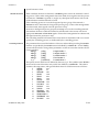
Below is a generic format for man pages. The man pages of each manual
section generally follow this order, but include only needed headings. For
example, if there are no bugs to report, there is no BUGS section. See the intro
pages for more information and detail about each section, and man(1) for more
information about man pages in general.
NAME
This section gives the names of the commands or functions documented,
followed by a brief description of what they do.
SYNOPSIS
This section shows the syntax of commands or functions. When a command or
file does not exist in the standard path, its full pathname is shown. Literal
characters (commands and options) are in bold font and variables (arguments,
parameters and substitution characters) are in italic font. Options and
ii
arguments are alphabetized, with single letter arguments first, and options with
arguments next, unless a different argument order is required.
The following special characters are used in this section:
[]
The option or argument enclosed in these brackets is optional. If the
brackets are omitted, the argument must be specified.
...
Ellipses. Several values may be provided for the previous argument, or
the previous argument can be specified multiple times, for example,
‘filename . . .’.
|
Separator. Only one of the arguments separated by this character can
be specified at time.
{}
Braces. The options and/or arguments enclosed within braces are
interdependent, such that everything enclosed must be treated as a
unit.
PROTOCOL
This section occurs only in subsection 3R to indicate the protocol description
file. The protocol specification pathname is always listed in bold font.
AVAILABILITY
This section briefly states any limitations on the availabilty of the command.
These limitations could be hardware or software specific.
A specification of a class of hardware platform, such as x86 or SPARC, denotes
that the command or interface is applicable for the hardware platform specified.
In Section 1 and Section 1M, AVAILABILITY indicates which package contains
the command being described on the manual page. In order to use the
command, the specified package must have been installed with the operating
system. If the package was not installed, see pkgadd(1) for information on how
to upgrade.
MT-LEVEL
This section lists the MT-LEVEL of the library functions described in the
Section 3 manual pages. The MT-LEVEL defines the libraries’ ability to support
threads. See Intro(3) for more information.
Preface
iii
DESCRIPTION
This section defines the functionality and behavior of the service. Thus it
describes concisely what the command does. It does not discuss OPTIONS or
cite EXAMPLES. Interactive commands, subcommands, requests, macros,
functions and such, are described under USAGE.
IOCTL
This section appears on pages in Section 7 only. Only the device class which
supplies appropriate parameters to the ioctl(2) system call is called ioctl and
generates its own heading. ioctl calls for a specific device are listed
alphabetically (on the man page for that specific device). ioctl calls are used for
a particular class of devices all of which have an io ending, such as mtio(7).
OPTIONS
This lists the command options with a concise summary of what each option
does. The options are listed literally and in the order they appear in the
SYNOPSIS section. Possible arguments to options are discussed under the
option, and where appropriate, default values are supplied.
OPERANDS
This section lists the command operands and describes how they affect the
actions of the command.
OUTPUT
This section describes the output - standard output, standard error, or output
files - generated by the command.
RETURN VALUES
If the man page documents functions that return values, this section lists these
values and describes the conditions under which they are returned. If a
function can return only constant values, such as 0 or −1, these values are listed
in tagged paragraphs. Otherwise, a single paragraph describes the return
values of each function. Functions declared as void do not return values, so
they are not discussed in RETURN VALUES.
iv
ERRORS
On failure, most functions place an error code in the global variable errno
indicating why they failed. This section lists alphabetically all error codes a
function can generate and describes the conditions that cause each error. When
more than one condition can cause the same error, each condition is described
in a separate paragraph under the error code.
USAGE
This section is provided as a guidance on use. This section lists special rules,
features and commands that require in-depth explanations. The subsections
listed below are used to explain built-in functionality:
Commands
Modifiers
Variables
Expressions
Input Grammar
EXAMPLES
This section provides examples of usage or of how to use a command or
function. Wherever possible a complete example including command line entry
and machine response is shown. Whenever an example is given, the prompt is
shown as
example%
or if the user must be super-user,
example#
Examples are followed by explanations, variable substitution rules, or returned
values. Most examples illustrate concepts from the SYNOPSIS, DESCRIPTION,
OPTIONS and USAGE sections.
ENVIRONMENT
This section lists any environment variables that the command or function
affects, followed by a brief description of the effect.
Preface
v
EXIT STATUS
This section lists the values the command returns to the calling program or shell
and the conditions that cause these values to be returned. Usually, zero is
returned for successful completion and values greater than zero for various
error conditions.
FILES
This section lists all filenames referred to by the man page, files of interest, and
files created or required by commands. Each is followed by a descriptive
summary or explanation.
SEE ALSO
This section lists references to other man pages, in-house documentation and
outside publications.
DIAGNOSTICS
This section lists diagnostic messages with a brief explanation of the condition
causing the error. Messages appear in bold font with the exception of variables,
which are in italic font.
WARNINGS
This section lists warnings about special conditions which could seriously affect
your working conditions — this is not a list of diagnostics.
NOTES
This section lists additional information that does not belong anywhere else on
the page. It takes the form of an aside to the user, covering points of special
interest. Critical information is never covered here.
BUGS
This section describes known bugs and wherever possible suggests
workarounds.
vi
SunOS 5.5
Device and Network Interfaces
NAME
DESCRIPTION
Intro ( 7 )
Intro, intro − introduction to special files
This section describes various device and network interfaces available on the system.
The types of interfaces described include character and block devices, STREAMS
modules, network protocols, file systems, and ioctl requests for driver subsystems and
classes.
This section contains the following major collections:
(7D)
The system provides drivers for a variety of hardware devices, such as disk,
magnetic tapes, serial communication lines, mice, and frame buffers, as well as
virtual devices such as pseudo-terminals and windows.
This section describes special files that refer to specific hardware peripherals
and device drivers. STREAMS device drivers are also described. Characteristics
of both the hardware device and the corresponding device driver are discussed
where applicable.
An application accesses a device through that device’s special file. This section
specifies the device special file to be used to access the device as well as application programming interface (API) information relevant to the use of the device
driver.
All device special files are located under the /devices directory. The /devices
directory hierarchy attempts to mirror the hierarchy of system busses, controllers, and devices configured on the system. Logical device names for special files
in /devices are located under the /dev directory. Although not every special file
under /devices will have a corresponding logical entry under /dev, whenever
possible, an application should reference a device using the logical name for the
device. Logical device names are listed in the FILES section of the page for the
device in question.
This section also describes driver configuration where applicable. Many device
drivers have a driver configuration file of the form driver_name.conf associated
with them (see driver.conf(4)). The configuration information stored in the
driver configuration file is used to configure the driver and the device. Driver
configuration files are located in /kernel/drv and /usr/kernel/drv. Driver
configuration files for platform dependent drivers are located in
/platform/‘uname -i‘/kernel/drv where ‘uname -i‘ is the output of the uname(1)
command with the -i option.
Some driver configuration files may contain user configurable properties.
Changes in a driver’s configuration file will not take effect until the system is
rebooted or the driver has been removed and re-added (see rem_drv(1M) and
add_drv(1M)).
modified 29 Sep 1994
(7FS)
This section describes the programmatic interface for several file systems supported by SunOS.
(7I)
This section describes ioctl requests which apply to a class of drivers or subsystems. For example, ioctl requests which apply to most tape devices are
7-5
Intro ( 7 )
Device and Network Interfaces
SunOS 5.5
discussed in mtio(7I). Ioctl requests relevant to only a specific device are
described on the man page for that device. The page for the device in question
should still be examined for exceptions to the ioctls listed in section 7I.
(7M)
This section describes STREAMS modules. Note that STREAMS drivers are discussed in section 7D. streamio(7I) contains a list of ioctl requests used to manipulate STREAMS modules and interface with the STREAMS framework. Ioctl
requests specific to a STREAMS module will be discussed on the man page for
that module.
(7P)
This section describes various network protocols available in SunOS.
SunOS supports both socket-based and STREAMS-based network communications. The Internet protocol family, described in inet(7P), is the primary protocol family supported by SunOS, although the system can support a number of
others. The raw interface provides low-level services, such as packet fragmentation and reassembly, routing, addressing, and basic transport for socket-based
implementations. Facilities for communicating using an Internet-family protocol are generally accessed by specifying the AF_INET address family when binding a socket; see socket(3N) for details.
Major protocols in the Internet family include:
SEE ALSO
·
The Internet Protocol (IP) itself, which supports the universal datagram format, as described in ip(7P). This is the default protocol for SOCK_RAW type
sockets within the AF_INET domain.
·
The Transmission Control Protocol (TCP); see tcp(7P). This is the default
protocol for SOCK_STREAM type sockets.
·
The User Datagram Protocol (UDP); see udp(4P). This is the default protocol
for SOCK_DGRAM type sockets.
·
The Address Resolution Protocol (ARP); see arp(7P).
·
The Internet Control Message Protocol (ICMP); see icmp(7P).
add_drv(1M), rem_drv(1M), intro(2), ioctl(2), socket(3N), driver.conf(4), arp(7P),
icmp(7P), inet(7P), ip(7P), mtio(7I), st(7D), streamio(7I), tcp(7P), udp(7P)
Solaris 1.x to Solaris 2.x Transition Guide
TCP/IP and Data Communications Guide
STREAMS Programming Guide
Writing Device Drivers
7-6
modified 29 Sep 1994
SunOS 5.5
modified 29 Sep 1994
Device and Network Interfaces
Intro ( 7 )
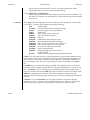
Name
Description
adp(7D)
low-level module for Adaptec 7870/7871/7872
based SCSI controllers
aha(7D)
low-level module for Adaptec 154x ISA host bus
adapters
aic(7D)
low-level module for Adaptec AIC-6360 based ISA
host bus adapters
arp(7P)
Address Resolution Protocol
ARP(7P)
See arp(7P)
asy(7D)
asynchronous serial port driver
ata(7D)
AT attachment disk driver
audio(7I)
generic audio device interface
audioamd(7D)
telephone quality audio device
audiocs(7D)
Crystal Semiconductor 4231 audio Interface
bd(7M)
SunButtons and SunDials STREAMS module
be(7D)
BigMAC Fast Ethernet device driver
bpp(7D)
bi-directional parallel port driver
bufmod(7M)
STREAMS Buffer Module
bwtwo(7D)
black and white memory frame buffer
cdio(7I)
CD-ROM control operations
cgeight(7D)
24-bit color memory frame buffer
cgfour(7D)
P4-bus 8-bit color memory frame buffer
cgfourteen(7D)
24-bit color graphics device
cgsix(7D)
accelerated 8-bit color frame buffer
cgthree(7D)
8-bit color memory frame buffer
cgtwo(7D)
color graphics interface
cmdk(7D)
common disk driver
connld(7M)
line discipline for unique stream connections
console(7D)
STREAMS-based console interface
corvette(7D)
low-level module for IBM Micro Channel SCSI-2
Fast/Wide Adapter/A
csa(7D)
low-level module for Compaq SMART SCSI Array
Controller
dbri(7D)
Dual Basic Rate ISDN and audio Interface
display(7D)
system console display
7-7
Intro ( 7 )
7-8
Device and Network Interfaces
SunOS 5.5
dkio(7I)
disk control operations
dlpi(7P)
Data Link Provider Interface
dnet(7D)
Ethernet driver for D-Link DE-530CT, SMC EtherPower 8432BT, Znyx312, Cogent EM960, Cogent
EM100
dpt(7D)
DPT 2011, 2012, 2021, 2022, 2122, 2024, 2124, 3021,
3222, and 3224 controllers
dsa(7D)
low-level module for Dell SCSI Array Controller
(DSA)
eepro(7D)
Intel EtherExpress-Pro Ethernet device driver
eha(7D)
low-level module for Adaptec 174x EISA host bus
adapter
el(7D)
3COM 3C503 Ethernet device driver
elink(7D)
3COM 3C507 Ethernet device driver
elx(7D)
3COM EtherLink III Ethernet device driver
esa(7D)
low-level module for Adaptec 7770 based SCSI controllers
esp(7D)
ESP SCSI Host Bus Adapter Driver
fbio(7I)
frame buffer control operations
fd(7D)
drivers for floppy disks and floppy disk controllers
fdc(7D)
See fd(7D)
fdio(7I)
floppy disk control operations
gld(7D)
Generic LAN Driver
hdio(7I)
SMD and IPI disk control operations
hsfs(7FS)
High Sierra & ISO 9660 CD-ROM filesystem
icmp(7P)
Internet Control Message Protocol
ICMP(7P)
See icmp(7P)
id(7D)
See ipi(7D)
ie(7D)
Intel 82586 Ethernet device driver
iee(7D)
Intel EtherExpress 16 Ethernet device driver
ieef(7D)
Intel EtherExpress Flash32/82596 Ethernet device
driver
if(7P)
See if_tcp(7P)
if_tcp(7P)
general properties of Internet Protocol network
interfaces
inet(7P)
Internet protocol family
ip(7P)
Internet Protocol
modified 29 Sep 1994
SunOS 5.5
modified 29 Sep 1994
Device and Network Interfaces
Intro ( 7 )
IP(7P)
See ip(7P)
ipd(7M)
See ppp(7M)
ipdcm(7M)
See ppp(7M)
ipdptp(7M)
See ppp(7M)
ipi(7D)
IPI driver
ipi3sc(7D)
See ipi(7D)
is(7D)
See ipi(7D)
isdnio(7I)
ISDN interfaces
isp(7D)
ISP SCSI Host Bus Adapter Driver
iss(7D)
low-level module for Tricord System’s SCSI host
bus adapter
kb(7M)
keyboard STREAMS module
kdmouse(7D)
built-in mouse device interface
keyboard(7D)
system console keyboard
kmem(7D)
See mem(7D)
kstat(7D)
kernel statistics driver
ksyms(7D)
kernel symbols
ldterm(7M)
standard STREAMS terminal line discipline module
le(7D)
Am7990 (LANCE) Ethernet device driver
lebuffer(7D)
See le(7D)
ledma(7D)
See le(7D)
leo(7D)
double-buffered 24-bit SBus color frame buffer and
graphics accelerator
llc1(7D)
Logical Link Control Protocol Class 1 Driver
lofs(7FS)
loopback virtual file system
log(7D)
interface to STREAMS error logging and event tracing
logi(7D)
LOGITECH Bus Mouse device interface
lp(7D)
driver for parallel port
mcis(7D)
low-level module for IBM MicroChannel host bus
adapter
mcpp(7D)
ALM-2 Parallel Printer port driver
mcpzsa(7D)
ALM-2 Zilog 8530 SCC serial communications
driver
mem(7D)
physical or virtual memory
mlx(7D)
low-level module for Mylex DAC960 EISA and IBM
7-9
Intro ( 7 )
Device and Network Interfaces
SunOS 5.5
DMC960 Micro Channel host bus adapter series
7-10
msm(7D)
Microsoft Bus Mouse device interface
mt(7D)
tape interface
mtio(7I)
general magnetic tape interface
ncrs(7D)
low-level module for NCR 53C710, 53C810, 53C815,
53C820, and 53C825 host bus adapters
nee(7D)
Novell NE3200 Ethernet device Driver
nei(7D)
Novell NE2000, NE2000plus Ethernet device Driver
nfe(7D)
Compaq Netflex-2 Dualport Ethernet and
ENET/TR Drivers
null(7D)
the null file
openprom(7D)
PROM monitor configuration interface
pcelx(7D)
3COM EtherLink III PCMCIA Ethernet Adapter
pcfs(7FS)
DOS formatted file system
PCFS(7FS)
See pcfs(7FS)
pcic(7D)
Intel i82365SL PC Card Interface Controller
pckt(7M)
STREAMS Packet Mode module
pcmem(7D)
PCMCIA memory card nexus driver
pcn(7D)
AMD PCnet Ethernet controller device driver
pcram(7D)
PCMCIA RAM memory card device driver
pcscsi(7D)
low-level module for the AMD PCscsi, PCscsi II,
and PCnet-SCSI PCI-to-SCSI bus adapters
pcser(7D)
PCMCIA serial card device driver
pe(7D)
Xircom Pocket Ethernet device driver
pfmod(7M)
STREAMS Packet Filter Module
pipemod(7M)
STREAMS pipe flushing module
pln(7D)
SPARCstorage Array SCSI Host Bus Adapter Driver
pn(7D)
See ipi(7D)
ppp(7M)
STREAMS modules and drivers for the Point-toPoint Protocol
ppp_diag(7M)
See ppp(7M)
ptem(7M)
STREAMS Pseudo Terminal Emulation module
ptm(7D)
STREAMS pseudo-tty master driver
pts(7D)
STREAMS pseudo-tty slave driver
pty(7D)
pseudo-terminal driver
qe(7D)
QEC/MACE Ethernet device driver
modified 29 Sep 1994
SunOS 5.5
modified 29 Sep 1994
Device and Network Interfaces
Intro ( 7 )
qec(7D)
QEC bus nexus device driver
quotactl(7I)
manipulate disk quotas
riles(7D)
device driver for the Racal Interlan ES-3210 Ethernet Adapter
sad(7D)
STREAMS Administrative Driver
sbpro(7D)
Sound Blaster Pro, Sound Blaster 16, and Sound
Blaster AWE32 audio device driver
sd(7D)
driver for SCSI disk and CD-ROM devices
smc(7D)
SMC 8003/8013/8216/8416 Ethernet device driver
smce(7D)
SMC 3032/EISA dual-channel Ethernet device
driver
smceu(7D)
SMC Elite32 Ultra (8232) Ethernet device driver
smcf(7D)
SMC Ether100 (9232) Ethernet device driver
soc(7D)
Serial Optical Controller (SOC) device driver
sockio(7I)
ioctls that operate directly on sockets
ssd(7D)
driver for SPARCstorage Array disk devices
st(7D)
driver for SCSI tape devices
stc(7D)
Serial Parallel Communications driver for SBus
stp4020(7D)
STP 4020 PCMCIA Adapter
streamio(7I)
STREAMS ioctl commands
tcp(7P)
Internet Transmission Control Protocol
TCP(7P)
See tcp(7P)
tcx(7D)
24-bit SBus color memory frame buffer
termio(7I)
general terminal interface
termiox(7I)
extended general terminal interface
ticlts(7D)
loopback transport providers
ticots(7D)
See ticlts(7D)
ticotsord(7D)
See ticlts(7D)
timod(7M)
Transport Interface cooperating STREAMS module
tiqmouse(7D)
integrated mouse device interface
tirdwr(7M)
Transport Interface read/write interface STREAMS
module
tmpfs(7FS)
memory based filesystem
tpf(7D)
Platform Specific Module (PSM) for Tricord Systems Enterprise Server Models ES3000, ES4000 and
ES5000.
7-11
Intro ( 7 )
7-12
Device and Network Interfaces
SunOS 5.5
tr(7D)
IBM 16/4 Token Ring Network Adapter device
driver
trantor(7D)
low-level module for Trantor T348 Parallel SCSI
host bus adapter
ttcompat(7M)
V7, 4BSD and XENIX STREAMS compatibility
module
tty(7D)
controlling terminal interface
udp(7P)
Internet User Datagram Protocol
UDP(7P)
See udp(7P)
visual_io(7I)
Solaris VISUAL I/O control operations
volfs(7FS)
Volume Management file system
vuid2ps2(7M)
See vuidmice(7M)
vuid3ps2(7M)
See vuidmice(7M)
vuidm3p(7M)
See vuidmice(7M)
vuidm4p(7M)
See vuidmice(7M)
vuidm5p(7M)
See vuidmice(7M)
vuidmice(7M)
converts mouse protocol to Firm Events
wscons(7D)
workstation console
xd(7D)
disk driver for Xylogics 7053 SMD Disk Controller
xdc(7D)
See xd(7D)
xt(7D)
driver for Xylogics 472 1/2 inch tape controller
xy(7D)
disk driver for Xylogics 450 and 451 SMD Disk Controllers
xyc(7D)
See xy(7D)
zero(7D)
source of zeroes
zs(7D)
Zilog 8530 SCC serial communications driver
zsh(7D)
On-board serial HDLC/SDLC interface
modified 29 Sep 1994
SunOS 5.5
Devices
NAME
SYNOPSIS
adp ( 7D )
adp − low-level module for Adaptec 7870/7871/7872 based SCSI controllers
adp@reg
AVAILABILITY
x86
DESCRIPTION
The adp module provides low-level interface routines between the common disk/tape
I/O system and SCSI (Small Computer System Interface) controllers based on the Adaptec AIC-7870, AIC-7871, and AIC7872 SCSI chip. These controllers include the Adaptec 2940
and 2940W, and 3940 and 3940W, as well as motherboards with an embedded AIC-7870,
AIC-7871, and AIC-7872 SCSI chip.
The adp module can be configured for disk and streaming tape support for one or more
host adapter boards, each of which must be the sole initiator on a SCSI bus. Auto
configuration code determines if the adapter is present at the configured address and
what types of devices are attached to the adapter.
The device address, reg, is derived from bits 3-7 of the PCI device number.
FILES
modified 21 Nov 1994
/kernel/drv/adp.conf
configuration file for the adp driver. There are no userconfigurable options in this file.
7D-13
aha ( 7D )
Devices
NAME
SunOS 5.5
aha − low-level module for Adaptec 154x ISA host bus adapters
AVAILABILITY
x86
DESCRIPTION
The aha module provides low-level interface routines between the common disk/tape
I/O subsystem and the Adaptec ISA bus master 154x SCSI (Small Computer System
Interface) controllers. The aha module can be configured for disk and streaming tape
support for one or more host adapter boards, each of which must be the sole initiator on
a SCSI bus. Auto configuration code determines if the adapter is present at the configured
address and what types of devices are attached to it.
Board Configuration
and Auto
Configuration
The driver attempts to initialize itself in accordance with the information found in the
configuration file, /kernel/drv/aha.conf. The relevant user configurable items in this file
are:
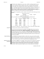
io port reg=0x330,0,0 ioaddr=0x330 ,
dma channel dmachan=6 ,
dma speed dmaspeed=0 ,
bus on time buson=5 , and
bus off time busoff=9 .
The I/O port is the ISA bus I/O address used for communication with the adapter. The
direct memory access (DMA) channel should be set to the manufacturer’s default of 5 for
the primary adapter. The DMA speed, bus on time, and bus off times may be set for
optimum performance with each ISA motherboard. Refer to the Adaptec AHA-1540/1542
User’s Manual for instructions. All jumpers on the board should be set (or verified) to conform the the configuration file.
The 154xC and the 154xCF should be set to default values. Specifically, disable BIOS support for drives with more than 1024 cylinders and more than two BIOS drives. Make sure
that the DMA transfer speed does not exceed the capabilities of the motherboard: most
can not be run faster than the default 5.7.
The default configurations described in the Adaptec AHA-1540/1542 User’s Manual should
be used for standard configurations of the system. If more than one board is to be used in
a single system, each must at least occupy a different set of address ranges and use a different DMA channel. Use of a different interrupt level for each board is required.
The default listing of the configuration file is as follows:
#
# primary controller [Settings for CD-ROM
#
name="aha" class="sysbus" reg=0x330,0,0
ioaddr=0x330 dmachan=6 dmaspeed=0 buson=5 busoff=9;
7D-14
modified 14 Mar 1994
SunOS 5.5
Devices
aha ( 7D )
#
# another controller example
#
name="aha" class="sysbus" reg=0x234,0,0
ioaddr=0x234 dmachan=6 dmaspeed=0 buson=5 busoff=9;
After installation, 154x controllers may be jumpered for any of the I/O address, IRQ, and
DMA channel combinations supported by the hardware, provided that this is reflected in
the configuration file and that the parameters do not conflict with other devices on the
system.
modified 14 Mar 1994
7D-15
aic ( 7D )
Devices
NAME
SYNOPSIS
SunOS 5.5
aic − low-level module for Adaptec AIC-6360 based ISA host bus adapters
aic@ioaddr,0
AVAILABILITY
x86
DESCRIPTION
The aic module provides low-level interface routines between the common disk/tape I/O
subsystem and AIC-6360 based SCSI (Small Computer System Interface) bus controllers. It
also provides support for the Adaptec AHA-1510A, AHA-1520A, and AHA-1522A SCSI controllers. It supports the AIC-6360 SCSI controller on the Sound Blaster 16 SCSI-2 board but
does not support the audio functions — the sbpro(7D) driver provides these capabilities.
Note that the AHA-1510A board and the SCSI port on the Sound Blaster 16 SCSI-2 board
can only be used as a secondary controller — not a primary (boot) controller.
The aic module can be configured for disk and streaming tape support for one or two
host adapter boards, each of which must be the sole initiator on a SCSI bus.
Autoconfiguration code determines if the adapter is present at the configured address
and determines what types of devices are attached to the adapter.
CONFIGURATION
The driver attempts to initialize itself using the information found in the configuration
file, aic.conf.
If multiple boards are configured in a single system, each board must occupy a different
I/O base address in the system I/O address space. Each board must also be assigned a
different IRQ level.
The AHA-1522 or AHA-1520A controller can be used as a primary boot controller only at
I/O base address 0x340 (unless special BIOS from Adaptec is procured). Therefore, if a
system installation is performed using a SCSI device (such as a CD-ROM drive) connected
to one of these adapters, the adapter must be configured with I/O base address 0x340.
(The adapter BIOS supports booting from this address only.)
Refer to the AHA-1520A/1522A AT-to-SCSI Host Adapters Installation Guide provided with
the controller for instructions on installation of the adapter and the valid jumper settings.
The default jumper configuration described in the AHA-1520A/1522A AT-to-SCSI Host
Adapters Installation Guide is the recommended configuration for the controller.
FILES
SEE ALSO
NOTES
/kernel/drv/aic.conf
aic device driver configuration file
driver.conf(4), sysbus(4), sbpro(7D)
The aic driver does not support direct memory access (DMA).
The aic driver does not support SCSI timeouts.
7D-16
modified 6 Oct 1994
SunOS 5.5
Protocols
NAME
SYNOPSIS
arp ( 7P )
arp, ARP − Address Resolution Protocol
#include <sys/fcntl.h>
#include <sys/socket.h>
#include <net/if_arp.h>
#include <netinet/in.h>
s = socket(AF_INET, SOCK_DGRAM, 0);
d = open ("/dev/arp", oflag);
DESCRIPTION
ARP is a protocol used to map dynamically between Internet Protocol (IP) and 10Mb/s
Ethernet addresses. It is used by all the 10Mb/s Ethernet datalink providers (interface
drivers) and it can be used by other datalink providers that support broadcast (such as
FDDI and Token Ring). ARP is not specific to the Internet Protocol but this implementation supports only that network layer protocol.
ARP caches IP-to-Ethernet address mappings. When an interface requests a mapping for
an address not in the cache, ARP queues the message that requires the mapping and
broadcasts a message on the associated network requesting the address mapping. If a
response is provided, the new mapping is cached and any pending message is transmitted. ARP will queue at most four packets while waiting for a mapping request to be
responded to; only the four most recently transmitted packets are kept.
APPLICATION
PROGRAMMING
INTERFACE
The STREAMS device /dev/arp is not a Transport Level Interface (TLI) transport provider
and may not be used with the TLI interface.
To facilitate communications with systems which do not use ARP, ioctl( ) requests are
provided to enter and delete entries in the IP-to-Ethernet tables.
#include <sys/sockio.h>
#include <sys/socket.h>
#include <net/if.h>
#include <net/if_arp.h>
struct arpreq arpreq;
ioctl(s, SIOCSARP, (caddr_t)&arpreq);
ioctl(s, SIOCGARP, (caddr_t)&arpreq);
ioctl(s, SIOCDARP, (caddr_t)&arpreq);
Each ioctl( ) request takes the same structure as an argument. SIOCSARP sets an ARP
entry, SIOCGARP gets an ARP entry, and SIOCDARP deletes an ARP entry. These ioctl( )
requests may be applied to any Internet family socket descriptor s, or to a descriptor for
the ARP device, but only by the privileged user.
modified 23 Aug 1994
7P-17
arp ( 7P )
Protocols
SunOS 5.5
The arpreq structure contains:
/∗
∗ ARP ioctl request
∗/
struct arpreq {
struct sockaddr
struct sockaddr
int
};
arp_pa;
arp_ha;
arp_flags;
/∗ protocol address ∗/
/∗ hardware address ∗/
/∗ flags ∗/
/∗ arp_flags field values ∗/
#define ATF_COM
0x2 /∗ completed entry (arp_ha valid) ∗/
#define ATF_PERM
0x4 /∗ permanent entry ∗/
#define ATF_PUBL
0x8 /∗ publish (respond for other host) ∗/
#define ATF_USETRAILERS 0x10 /∗ send trailer packets to host ∗/
The address family for the arp_pa sockaddr must be AF_INET; for the arp_ha sockaddr it
must be AF_UNSPEC. The only flag bits that may be written are ATF_PUBL and
ATF_USETRAILERS. ATF_PERM makes the entry permanent if the ioctl( ) request
succeeds. The peculiar nature of the ARP tables may cause the ioctl( ) request to fail if too
many permanent IP addresses hash to the same slot. ATF_PUBL specifies that the ARP
code should respond to ARP requests for the indicated host coming from other machines.
This allows a host to act as an “ARP server”, which may be useful in convincing an ARPonly machine to talk to a non-ARP machine.
ARP is also used to negotiate the use of trailer IP encapsulations; trailers are an alternate
encapsulation used to allow efficient packet alignment for large packets despite variablesized headers. Hosts that wish to receive trailer encapsulations so indicate by sending
gratuitous ARP translation replies along with replies to IP requests; they are also sent in
reply to IP translation replies. The negotiation is thus fully symmetrical, in that either or
both hosts may request trailers. The ATF_USETRAILERS flag is used to record the receipt
of such a reply, and enables the transmission of trailer packets to that host.
ARP watches passively for hosts impersonating the local host (that is, a host which
responds to an ARP mapping request for the local host’s address).
SEE ALSO
arp(1M), ifconfig(1M), if_tcp(7P), inet(7P)
Plummer, Dave, ‘‘An Ethernet Address Resolution Protocol -or- Converting Network Protocol
Addresses to 48.bit Ethernet Addresses for Transmission on Ethernet Hardware,’’ RFC 826, Network Information Center, SRI International, Menlo Park, Calif., November 1982.
Leffler, Sam, and Michael Karels, ‘‘Trailer Encapsulations,’’ RFC 893, Network Information
Center, SRI International, Menlo Park, Calif., April 1984.
DIAGNOSTICS
7P-18
IP: Hardware address ’%x:%x:%x:%x:%x:%x’ trying to be our address ’%d.%d.%d.%d’!
Duplicate IP address. ARP has discovered another host on the local network which
responds to mapping requests for the Internet address of this system.
modified 23 Aug 1994
SunOS 5.5
Protocols
arp ( 7P )
IP: Proxy ARP problem? Hardware address ’%x:%x:%x:%x:%x:%x’ thinks it is
’%d.%d.%d.%d’
This message will appear if arp(1M) has been used to create a published entry
and some other host on the local network responds to mapping requests for the
published arp entry.
modified 23 Aug 1994
7P-19
asy ( 7D )
Devices
NAME
SYNOPSIS
SunOS 5.5
asy − asynchronous serial port driver
#include <fcntl.h>
#include <sys/termios.h>
open("/dev/ttynn", mode);
open("/dev/ttydn", mode);
open("/dev/cuan", mode);
AVAILABILITY
x86
DESCRIPTION
The asy module is a loadable STREAMS driver that provides basic support for the standard UARTS that use Intel-8250, National Semiconductor-16450/16550 hardware,
together with basic asynchronous communication support. The driver supports those
termio(7I) device control functions specified by flags in the c_cflag word of the termios
structure and by the IGNBRK, IGNPAR, PARMRK, or INPCK flags in the c_iflag word of
the termios structure. All other termio(7I) functions must be performed by STREAMS
modules pushed atop the driver. When a device is opened, the ldterm(7M) and
ttcompat(7M) STREAMS modules are automatically pushed on top of the stream, providing the standard termio(7I) interface.
The character-special devices /dev/tty00 and /dev/tty01 are used to access the two standard serial ports (COM1 and COM2) on an x86 system. The asy driver supports up to four
serial ports, including the standard ports. These ttynn devices have minor device
numbers in the range 00-03.
By convention these same devices may be given names of the form /dev/ttydn, where n
denotes which line is to be accessed. Such device names are typically used to provide a
logical access point for a dial-in line being used with a modem.
To allow a single tty line to be connected to a modem and used for both incoming and
outgoing calls, a special feature, controlled by the minor device number, is available. By
accessing character-special devices with names of the form /dev/cuan it is possible to
open a port without the Carrier Detect signal being asserted, either through hardware or
an equivalent software mechanism. These devices are commonly known as dial-out lines.
APPLICATION
PROGRAMMING
INTERFACE
7D-20
Once a /dev/cuan line is opened, the corresponding tty, or ttyd line cannot be opened
until the /dev/cuan line is closed; a blocking open will wait until the /dev/cuan line is
closed (which will drop Data Terminal Ready, after which Carrier Detect will usually
drop as well) and carrier is detected again, and a non-blocking open will return an error.
Also, if the /dev/ttydn line has been opened successfully (usually only when carrier is
recognized on the modem) the corresponding /dev/cuan line can not be opened. This
allows a modem to be attached to, for example, /dev/ttyd0 (renamed from /dev/tty00)
and used for dial-in (by enabling the line for login in /etc/inittab) and also used for dialout (by tip(1) or uucp(1C)) as /dev/cua0 when no one is logged in on the line.
modified 24 May 1995
SunOS 5.5
Devices
IOCTLS
asy ( 7D )
The standard set of termio ioctl( ) calls are supported by asy.
Breaks can be generated by the TCSBRK, TIOCSBRK, and TIOCCBRK ioctl( ) calls.
The input and output line speeds may be set to any of the speeds supported by termio.
The speeds cannot be set independently; when the output speed is set, the input speed is
set to the same speed.
ERRORS
FILES
SEE ALSO
DIAGNOSTICS
An open( ) will fail if:
ENXIO
The unit being opened does not exist.
EBUSY
The dial-out device is being opened and the dial-in device is already
open, or the dial-in device is being opened with a no-delay open and the
dial-out device is already open.
EBUSY
The unit has been marked as exclusive-use by another process with a
TIOCEXCL ioctl( ) call.
EINTR
The open was interrupted by the delivery of a signal.
/dev/tty[00-03]
/dev/ttyd[0-3]
/dev/cua[0-3]
/kernel/drv/asy.conf
hardwired tty lines
dial-in tty lines
dial-out tty lines
asy configuration file.
tip(1), uucp(1C), ldterm(7M), termio(7I), ttcompat(7M)
asyn : silo overflow.
The hardware overrun occurred before the input character could be serviced.
asyn : ring buffer overflow.
The driver’s character input ring buffer overflowed before it could be serviced.
modified 24 May 1995
7D-21
ata ( 7D )
Devices
NAME
SYNOPSIS
SunOS 5.5
ata − AT attachment disk driver
ata@ioaddr,0
AVAILABILITY
x86
DESCRIPTION
The ata driver supports disk and CD-ROM interfaces conforming to the AT Attachment
specification including IDE interfaces. It excludes the MFM, RLL, ST506, and ST412 interfaces. Support is provided for CD_ROM drives that conform to the Small Form Factor
(SFF) ATA Packet Interface (ATAPI) specification: SFF-8020 revision 1.2.
CONFIGURATION
The driver initializes itself in accordance with the information found in the configuration
file ata.conf (see below). The only user configurable items in this file are:
drive0_block_factor
drive1_block_factor
ATA controllers support some amount of buffering (blocking). The purpose is to
interrupt the host when an entire buffer full of data has been read or written
instead of using an interrupt for each sector. This reduces interrupt overhead
and significantly increases throughput. The driver interrogates the controller to
find the buffer size. Some controllers hang when buffering is used, so the values
in the configuration file are used by the driver to reduce the effect of buffering
(blocking). The values presented may be chosen from 0x1, 0x2, 0x4, 0x8 and 0x10.
The values as shipped are set to 0x1, and they can be tuned to increase performance.
If your controller hangs when attempting to use higher block factors, you may be
unable to reboot the system. It is recommended that the tuning be carried out
using a duplicate of the /kernel directory subtree. This will ensure that a bootable kernel subtree exists in the event of a failed test.
max_transfer
This value controls the size of individual requests for consecutive disk sectors.
The value may range from 0x1 to 0x100. Higher values yield higher throughput.
The system is shipped with a value of 0x100, which probably should not be
changed.
EXAMPLES
7D-22
The following is an example configuration file.
#
# primary controller
#
# for higher performance - set block factor to 16
name="ata" class="sysbus" intr=5,14 reg=0x1f0,0,0
ioaddr1=0x1f0 ioaddr2=0x3f0
drive0_block_factor=0x1 drive1_block_factor=0x1
max_transfer=0x100
flow_control="dmult" queue="qsort" disk="dadk" ;
modified 14 Mar 1995
SunOS 5.5
Devices
ata ( 7D )
#
# secondary controller
#
name="ata" class="sysbus" intr=5,15 reg=0x170,0,0
ioaddr1=0x170 ioaddr2=0x370
drive0_block_factor=0x1 drive1_block_factor=0x1
max_transfer=0x100
flow_control="dmult" queue="qsort" disk="dadk" ;
FILES
SEE ALSO
modified 14 Mar 1995
/kernel/drv/ata
/kernel/drv/ata.conf
the driver
the configuration file
aha(7D), cmdk(7D), dpt(7D), eha(7D)
7D-23
audio ( 7I )
Ioctl Requests
NAME
OVERVIEW
SunOS 5.5
audio − generic audio device interface
The audio interface described below is an uncommitted interface and may be replaced in
the future.
An audio device is used to play and/or record a stream of audio data. Since a specific
audio device may not support all of the functionality described below, refer to the
device-specific manual pages for a complete description of each hardware device. An
application can use the AUDIO_GETDEV ioctl(2) to determine the current audio
hardware associated with /dev/audio.
AUDIO
FORMATS
Digital audio data represents a quantized approximation of an analog audio signal
waveform. In the simplest case, these quantized numbers represent the amplitude of the
input waveform at particular sampling intervals. In order to achieve the best approximation of an input signal, the highest possible sampling frequency and precision should be
used. However, increased accuracy comes at a cost of increased data storage requirements. For instance, one minute of monaural audio recorded in µ-law format at 8 KHz
requires nearly 0.5 megabytes of storage, while the standard Compact Disc audio format
(stereo 16-bit linear PCM data sampled at 44.1 KHz) requires approximately 10 megabytes
per minute.
Audio data may be represented in several different formats. An audio device’s current
audio data format can be determined by using the AUDIO_GETINFO ioctl described
below.
An audio data format is characterized in the audio driver by four parameters: Sample
Rate, Encoding, Precision, and Channels. Refer to the device-specific manual pages for a
list of the audio formats that each device supports. In addition to the formats that the
audio device supports directly, other formats provide higher data compression. Applications may convert audio data to and from these formats when recording or playing.
Sample Rate
Sample rate is a number that represents the sampling frequency (in samples per second)
of the audio data.
Encodings
An encoding parameter specifies the audio data representation. µ-law encoding (pronounced mew-law) corresponds to CCITT G.711, and is the standard for voice data used
by telephone companies in the United States, Canada, and Japan. A-law encoding is also
part of G.711, and is the standard encoding for telephony elsewhere in the world. A-law
and µ-law audio data are sampled at a rate of 8000 samples per second with 12-bit precision, with the data compressed to 8-bit samples. The resulting audio data quality is
equivalent to that of standard analog telephone service.
Linear Pulse Code Modulation (PCM) is an uncompressed audio format in which sample
values are directly proportional to audio signal voltages. Each sample is a 2’s complement number that represents a positive or negative amplitude.
7I-24
modified 21 Mar 1995
SunOS 5.5
Ioctl Requests
audio ( 7I )
Precision
Precision indicates the number of bits used to store each audio sample. For instance, µlaw and A-law data are stored with 8-bit precision. PCM data may be stored at various
precisions, though 16-bit PCM is most common.
Channels
Multiple channels of audio may be interleaved at sample boundaries. A sample frame
consists of a single sample from each active channel. For example, a sample frame of
stereo 16-bit PCM data consists of 2 16-bit samples, corresponding to the left and right
channel data.
DESCRIPTION
The device /dev/audio is a device driver that dispatches audio requests to the appropriate
underlying audio device driver. The audio driver is implemented as a STREAMS driver.
In order to record audio input, applications open(2) the /dev/audio device and read data
from it using the read(2) system call. Similarly, sound data is queued to the audio output
port by using the write(2) system call. Device configuration is performed using the
ioctl(2) interface.
As some systems may contain more than one audio device, application writers are
encouraged to query the AUDIODEV environment variable. If this variable is present in
the environment, its value should identify the path name of the default audio device.
Opening the Audio
Device
The audio device is treated as an exclusive resource − only one process can open the device at a time. However, two processes may simultaneously access the device: if one opens
it read-only, then another may open it write-only.
When a process cannot open /dev/audio because the requested access mode is busy:
·
if either the O_NDELAY or O_NONBLOCK flag are set in the open( ) oflag argument, then −1 is immediately returned, with errno set to EBUSY.
·
if neither the O_NDELAY nor the O_NONBLOCK flag are set, then open( )
hangs until the device is available or a signal is delivered to the process, in
which case a −1 is returned with errno set to EINTR. This allows a process to
block in the open call, while waiting for the audio device to become available.
Upon the initial open( ) of the audio device, the driver will reset the data format of the
device to the default state of 8-bit, 8Khz, mono µ-law data. If the device is already open
and a different audio format has been set, this will not be possible. Audio applications
should explicitly set the encoding characteristics to match the audio data requirements,
rather than depend on the default configuration.
Since the audio device grants exclusive read or write access to a single process at a time,
long-lived audio applications may choose to close the device when they enter an idle
state and reopen it when required. The play.waiting and record.waiting flags in the audio
information structure (see below) provide an indication that another process has
requested access to the device. For instance, a background audio output process may
choose to relinquish the audio device whenever another process requests write access.
Recording Audio
Data
modified 21 Mar 1995
The read( ) system call copies data from the system buffers to the application. Ordinarily,
read( ) blocks until the user buffer is filled. The I_NREAD ioctl (see streamio(7I)) may be
used to determine the amount of data that may be read without blocking. The device
may alternatively be set to a non-blocking mode, in which case read( ) completes
7I-25
audio ( 7I )
Ioctl Requests
SunOS 5.5
immediately, but may return fewer bytes than requested. Refer to the read(2) manual
page for a complete description of this behavior.
When the audio device is opened with read access, the device driver immediately starts
buffering audio input data. Since this consumes system resources, processes that do not
record audio data should open the device write-only (O_WRONLY).
The transfer of input data to STREAMS buffers may be paused (or resumed) by using the
AUDIO_SETINFO ioctl to set (or clear) the record.pause flag in the audio information structure (see below). All unread input data in the STREAMS queue may be discarded by
using the I_FLUSH STREAMS ioctl (see streamio(7I)). When changing record parameters,
the input stream should be paused and flushed before the change, and resumed afterward. Otherwise, subsequent reads may return samples in the old format followed by
samples in the new format. This is particularly important when new parameters result in
a changed sample size.
Input data can accumulate in STREAMS buffers very quickly. At a minimum, it will accumulate at 8000 bytes per second for 8-bit, 8 KHz, mono, µ-law data. If the device is
configured for 16-bit linear or higher sample rates, it will accumulate even faster. If the
application that consumes the data cannot keep up with this data rate, the STREAMS
queue may become full. When this occurs, the record.error flag is set in the audio information structure and input sampling ceases until there is room in the input queue for additional data. In such cases, the input data stream contains a discontinuity. For this reason,
audio recording applications should open the audio device when they are prepared to
begin reading data, rather than at the start of extensive initialization.
Playing Audio Data
The write( ) system call copies data from an applications buffer to the STREAMS output
queue. Ordinarily, write( ) blocks until the entire user buffer is transferred. The device
may alternatively be set to a non-blocking mode, in which case write( ) completes
immediately, but may have transferred fewer bytes than requested (see write(2)).
Although write( ) returns when the data is successfully queued, the actual completion of
audio output may take considerably longer. The AUDIO_DRAIN ioctl may be issued to
allow an application to block until all of the queued output data has been played. Alternatively, a process may request asynchronous notification of output completion by writing a zero-length buffer (end-of-file record) to the output stream. When such a buffer has
been processed, the play.eof flag in the audio information structure (see below) is incremented.
The final close(2) of the file descriptor hangs until audio output has drained. If a signal
interrupts the close( ), or if the process exits without closing the device, any remaining
data queued for audio output is flushed and the device is closed immediately.
The conversion of output data may be paused (or resumed) by using the
AUDIO_SETINFO ioctl to set (or clear) the play.pause flag in the audio information structure. Queued output data may be discarded by using the I_FLUSH STREAMS ioctl.
Output data will be played from the STREAMS buffers at a rate of at least 8000 bytes per
second for µ-law or A-law data (faster for 16-bit linear data or higher sampling rates). If
the output queue becomes empty, the play.error flag is set in the audio information
7I-26
modified 21 Mar 1995
SunOS 5.5
Ioctl Requests
audio ( 7I )
structure and output is stopped until additional data is written. If an application
attempts to write a number of bytes that is not a multiple of the current sample frame
size, an error will be generated and the device will need to be closed before any future
writes will succeed.
Asynchronous I/O
The I_SETSIG STREAMS ioctl enables asynchronous notification, through the SIGPOLL
signal, of input and output ready conditions. The O_NONBLOCK flag may be set using
the F_SETFL fcntl(2) to enable non-blocking read( ) and write( ) requests. This is normally
sufficient for applications to maintain an audio stream in the background.
Audio Control
Pseudo-Device
It is sometimes convenient to have an application, such as a volume control panel,
modify certain characteristics of the audio device while it is being used by an unrelated
process. The /dev/audioctl pseudo-device is provided for this purpose. Any number of
processes may open /dev/audioctl simultaneously. However, read( ) and write( ) system
calls are ignored by /dev/audioctl. The AUDIO_GETINFO and AUDIO_SETINFO ioctl
commands may be issued to /dev/audioctl to determine the status or alter the behavior of
/dev/audio. Note: In general, the audio control device name is constructed by appending
the letters "ctl" to the path name of the audio device.
Audio Status Change
Notification
Applications that open the audio control pseudo-device may request asynchronous
notification of changes in the state of the audio device by setting the S_MSG flag in an
I_SETSIG STREAMS ioctl. Such processes receive a SIGPOLL signal when any of the following events occur:
·
An AUDIO_SETINFO ioctl has altered the device state.
·
An input overflow or output underflow has occurred.
·
An end-of-file record (zero-length buffer) has been processed on output.
·
An open( ) or close( ) of /dev/audio has altered the device state.
·
An external event (such as speakerbox volume control) has altered the
device state.
IOCTLS
Audio Information
Structure
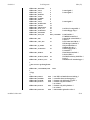
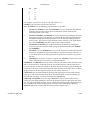
The state of the audio device may be polled or modified using the AUDIO_GETINFO and
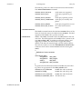
AUDIO_SETINFO ioctl commands. These commands operate on the audio_info structure as defined, in <sys/audioio.h>, as follows:
/∗ This structure contains state information for audio device
IO streams ∗/
struct audio_prinfo {
/∗ The following values describe the audio data encoding ∗/
uint_t sample_rate;
/∗ samples per second ∗/
uint_t channels;
/∗ number of interleaved channels ∗/
uint_t precision;
/∗ number of bits per sample ∗/
uint_t encoding;
/∗ data encoding method ∗/
/∗ The following values control audio device configuration ∗/
uint_t gain;
/∗ volume level ∗/
uint_t port;
/∗ selected I/O port ∗/
uint_t buffer_size;
/∗ I/O buffer size ∗/
/∗ The following values describe the current device state ∗/
modified 21 Mar 1995
7I-27
audio ( 7I )
Ioctl Requests
uint_t
uint_t
uchar_t
uchar_t
uchar_t
uchar_t
samples;
eof;
pause;
error;
waiting;
balance;
SunOS 5.5
/∗ number of samples converted ∗/
/∗ End Of File counter (play only) ∗/
/∗ non-zero if paused, zero to resume ∗/
/∗ non-zero if overflow/underflow ∗/
/∗ non-zero if a process wants access ∗/
/∗ stereo channel balance ∗/
/∗ The following values are read-only device state flags ∗/
uchar_t open;
/∗ non-zero if open access granted ∗/
uchar_t active;
/∗ non-zero if I/O active ∗/
uint_t avail_ports;
/∗ available I/O ports ∗/
} audio_prinfo_t;
/∗ This structure is used in AUDIO_GETINFO and AUDIO_SETINFO ioctl
commands ∗/
typedef struct audio_info {
audio_prinfo_t record;
/∗ input status information ∗/
audio_prinfo_t play;
/∗ output status information ∗/
uint_t
monitor_gain; /∗ input to output mix ∗/
uchar_t
output_muted; /∗ non-zero if output muted ∗/
} audio_info_t;
/∗ Audio encoding types ∗/
#define AUDIO_ENCODING_ULAW
#define AUDIO_ENCODING_ALAW
#define AUDIO_ENCODING_LINEAR
(1)
(2)
(3)
/∗ u-law encoding ∗/
/∗ A-law encoding ∗/
/∗ Linear PCM encoding ∗/
/∗ These ranges apply to record, play, and monitor gain values ∗/
#define AUDIO_MIN_GAIN
(0)
/∗ minimum gain value ∗/
#define AUDIO_MAX_GAIN
(255)
/∗ maximum gain value ∗/
/∗ These values apply to the balance field to adjust channel gain values ∗/
#define AUDIO_LEFT_BALANCE
(0)
/∗ left channel only ∗/
#define AUDIO_MID_BALANCE
(32)
/∗ equal left/right balance ∗/
#define AUDIO_RIGHT_BALANCE
(64)
/∗ right channel only ∗/
/∗ Define some convenient audio port names (for port and avail_ports) ∗/
/∗ output ports (several might be enabled at once) ∗/
#define AUDIO_SPEAKER
(0x01) /∗ output to built-in speaker ∗/
#define AUDIO_HEADPHONE
(0x02) /∗ output to headphone jack ∗/
#define AUDIO_LINE_OUT
(0x04) /∗ output to line out ∗/
/∗ input ports (usually only one may be enabled at a time) ∗/
#define AUDIO_MICROPHONE
(0x01) /∗ input from microphone ∗/
#define AUDIO_LINE_IN
(0x02) /∗ input from line in ∗/
#define
MAX_AUDIO_DEV_LEN(16)
/∗ Parameter for the AUDIO_GETDEV ioctl ∗/
typedef struct audio_device {
char name[MAX_AUDIO_DEV_LEN];
char version[MAX_AUDIO_DEV_LEN];
char config[MAX_AUDIO_DEV_LEN];
} audio_device_t;
The play.gain and record.gain fields specify the output and input volume levels. A value of
AUDIO_MAX_GAIN indicates maximum volume. Audio output may also be temporarily
muted by setting a non-zero value in the output_muted field. Clearing this field restores
7I-28
modified 21 Mar 1995
SunOS 5.5
Ioctl Requests
audio ( 7I )
audio output to the normal state. Most audio devices allow input data to be monitored
by mixing audio input onto the output channel. The monitor_gain field controls the level
of this feedback path.
The play.port field controls the output path for the audio device. It can be set to either
AUDIO_SPEAKER (built-in speaker), AUDIO_HEADPHONE (headphone jack), or
AUDIO_LINE_OUT (line-out port). For some devices, it may be set to a combination of
these ports. The play.avail_ports field returns the set of output ports that are currently
accessible. The input ports can be either AUDIO_MICROPHONE or AUDIO_LINE_IN.
The record.avail_ports field returns the set of input ports that are currently accessible.
The play.balance and record.balance fields are used to control the volume between the left
and right channels when manipulating stereo data. When the value is set between
AUDIO_LEFT_BALANCE and AUDIO_MID_BALANCE, the right channel volume will be
reduced in proportion to the balance value. Conversely, when balance is set between
AUDIO_MID_BALANCE and AUDIO_RIGHT_BALANCE, the left channel will be proportionally reduced.
The play.pause and record.pause flags may be used to pause and resume the transfer of
data between the audio device and the STREAMS buffers. The play.error and record.error
flags indicate that data underflow or overflow has occurred. The play.active and
record.active flags indicate that data transfer is currently active in the corresponding direction.
The play.open and record.open flags indicate that the device is currently open with the
corresponding access permission. The play.waiting and record.waiting flags provide an
indication that a process may be waiting to access the device. These flags are set
automatically when a process blocks on open( ), though they may also be set using the
AUDIO_SETINFO ioctl command. They are cleared only when a process relinquishes
access by closing the device.
The play.samples and record.samples fields are initialized, at open( ), to zero and increment
each time a data sample is copied to or from the associated STREAMS queue. Some audio
drivers may be limited to counting buffers of samples, instead of single samples for the
samples accounting. For this reason, applications should not assume that the samples
fields contain a perfectly accurate count. The play.eof field increments whenever a zerolength output buffer is synchronously processed. Applications may use this field to
detect the completion of particular segments of audio output.
The record.buffer_size field controls the amount of input data that is buffered in the device
driver during record operations. Applications that have particular requirements for low
latency should set the value appropriately. Note however that smaller input buffer sizes
may result in higher system overhead. The value of this field is specified in bytes and
drivers will constrain it to be a multiple of the current sample frame size. Some drivers
may place other requirements on the value of this field. Refer to the audio device-specific
manual page for more details. If an application changes the format of the audio device
and does not modify the record.buffer_size field, the device driver may use a default value
to compensate for the new data rate. Therefore, if an application wishes to modify this
field, it should modify it during or after the format change itself, not before. The
modified 21 Mar 1995
7I-29
audio ( 7I )
Ioctl Requests
SunOS 5.5
record.buffer_size field may be modified only on the /dev/audio device by processes that
have it opened for reading. The play.buffer_size field is currently not supported.
The audio data format is indicated by the sample_rate, channels, precision, and encoding
fields. The values of these fields correspond to the descriptions in the AUDIO FORMATS
section above. Refer to the audio device-specific manual pages for a list of supported
data format combinations.
The data format fields may be modified only on the /dev/audio device. The audio
hardware will often constrain the input and output data formats to be identical. If this is
the case, then the data format may not be changed if multiple processes have opened the
audio device.
If the parameter changes requested by an AUDIO_SETINFO ioctl cannot all be accommodated, ioctl( ) will return with errno set to EINVAL and no changes will be made to the
device state.
Streamio IOCTLS
Audio IOCTLS
All of the streamio(7I) ioctl commands may be issued for the /dev/audio device. Because
the /dev/audioctl device has its own STREAMS queues, most of these commands neither
modify nor report the state of /dev/audio if issued for the /dev/audioctl device. The
I_SETSIG ioctl may be issued for /dev/audioctl to enable the notification of audio status
changes, as described above.
The audio device additionally supports the following ioctl commands:
AUDIO_DRAIN
The argument is ignored. This command suspends the calling process until the
output STREAMS queue is empty, or until a signal is delivered to the calling process. It may not be issued for the /dev/audioctl device. An implicit
AUDIO_DRAIN is performed on the final close( ) of /dev/audio.
AUDIO_GETDEV
The argument is a pointer to an audio_device structure. This command may be
issued for either /dev/audio or /dev/audioctl. The returned value in the name
field will be a string that will identify the current /dev/audio hardware device,
the value in version will be a string indicating the current version of the
hardware, and config will be a device-specific string identifying the properties of
the audio stream associated with that file descriptor. Refer to the audio devicespecific manual pages to determine the actual strings returned by the device
driver.
AUDIO_GETINFO
The argument is a pointer to an audio_info structure. This command may be
issued for either /dev/audio or /dev/audioctl. The current state of the /dev/audio
device is returned in the structure.
7I-30
modified 21 Mar 1995
SunOS 5.5
Ioctl Requests
audio ( 7I )
AUDIO_SETINFO
The argument is a pointer to an audio_info structure. This command may be
issued for either the /dev/audio or the /dev/audioctl device with some restrictions. This command configures the audio device according to the structure supplied and overwrites the structure with the new state of the device. Note: The
play.samples, record.samples, play.error, record.error, and play.eof fields are modified
to reflect the state of the device when the AUDIO_SETINFO was issued. This
allows programs to automatically modify these fields while retrieving the previous value.
Certain fields in the information structure, such as the pause flags are treated as
read-only when /dev/audio is not open with the corresponding access permission. Other fields, such as the gain levels and encoding information, may have a
restricted set of acceptable values. Applications that attempt to modify such
fields should check the returned values to be sure that the corresponding change
took effect. The sample_rate, channels, precision, and encoding fields treated as
read-only for /dev/audioctl, so that applications can be guaranteed that the existing audio format will stay in place until they relinquish the audio device.
AUDIO_SETINFO will return EINVAL when the desired configuration is not possible, or EBUSY when another process has control of the audio device.
Once set, the following values persist through subsequent open( ) and close( )
calls of the device: play.gain, record.gain, play.balance, record.balance, output_muted,
monitor_gain, play.port, and record.port. However, an automatic device driver
unload will reset these parameters to their default values on the next load. All
other state is reset when the corresponding I/O stream of /dev/audio is closed.
The audio_info structure may be initialized through the use of the
AUDIO_INITINFO macro. This macro sets all fields in the structure to values that
are ignored by the AUDIO_SETINFO command. For instance, the following code
switches the output port from the built-in speaker to the headphone jack without
modifying any other audio parameters:
audio_info_tinfo;
AUDIO_INITINFO(&info);
info.play.port = AUDIO_HEADPHONE;
err = ioctl(audio_fd, AUDIO_SETINFO, &info);
This technique eliminates problems associated with using a sequence of
AUDIO_GETINFO followed by AUDIO_SETINFO.
ERRORS
modified 21 Mar 1995
An open( ) will fail if:
EBUSY
The requested play or record access is busy and either the O_NDELAY or
O_NONBLOCK flag was set in the open( ) request.
EINTR
The requested play or record access is busy and a signal interrupted the
open( ) request.
7I-31
audio ( 7I )
Ioctl Requests
SunOS 5.5
An ioctl( ) will fail if:
FILES
EINVAL
The parameter changes requested in the AUDIO_SETINFO ioctl are
invalid or are not supported by the device.
EBUSY
The parameter changes requested in the AUDIO_SETINFO ioctl could
not be made because another process has the device open and is using a
different format.
The physcial audio device names are system dependent and are rarely used by programmers. The programmer should use the generic device names listed below.
/dev/audio
/dev/audioctl
/dev/sound/0
/dev/sound/0ctl
symbolic link to the system’s primary audio device
symbolic link to the control device for /dev/audio
first audio device in the system
audio control device for /dev/sound/0
SEE ALSO
open(2), close(2), read(2), write(2), ioctl(2), fcntl(2), poll(2), audioamd(7D), audiocs(7D),
dbri(7D), sbpro(7D), streamio(7I)
BUGS
Due to a feature of the STREAMS implementation, programs that are terminated or exit
without closing the audio device may hang for a short period while audio output drains.
In general, programs that produce audio output should catch the SIGINT signal and flush
the output stream before exiting.
On LX machines running Solaris 2.3, catting a demo audio file to the audio device
/dev/audio does not work. Use the audioplay command on LX machines instead of cat.
FUTURE
DIRECTIONS
Future workstation audio resources will be managed by an audio foundation library. For
the time being, we encourage you to write your programs in a modular fashion, isolating
the audio device-specific functions, so that they may be easily ported to such an environment.
The AUDIO_GETDEV ioctl is provided for the future implementation of an audio device
capability database. In general, applications may use the play.avail_ports and
record.avail_ports fields of the audio_info structure to determine the audio device capabilities.
7I-32
modified 21 Mar 1995
SunOS 5.5
Devices
NAME
AVAILABILITY
audioamd ( 7D )
audioamd − telephone quality audio device
SPARC
SPARCstation 1 and 2, IPC, IPX, SLC, ELC, LC, and SPARCserver 6xx systems.
Desktop SPARCsystems include a built-in speaker for audio output. The audio cable provides connectors for a microphone and external headset. The headset output level is adequate to power most headphones, but may be too low for some external speakers.
Powered speakers or an external amplifier may be used. SPARCserver 6xx systems do not
have an internal speaker, but support an external microphone and speaker connected
through the audio cable.
The Sun Microphone is recommended for normal desktop audio recording. It contains a
battery that must be replaced after 210 hours of use. Other microphones may be used, but
a pre-amplifier circuit may be required to achieve a sufficient input signal. Other audio
sources may be recorded by connecting one channel of the line output to the audio cable
microphone input. If the input signal is distorted, external attenuation may be required
(audio sources may also be connected from their headphone output with the volume
turned down).
DESCRIPTION
The audioamd device uses the AM79C30A Digital Subscriber Controller chip to implement the audio device interface. This interface is described fully in the audio(7I) manual
page.
Applications that open /dev/audio may use the AUDIO_GETDEV ioctl to determine
which audio device is being used. The audioamd driver will return "SUNW,am79c30" in
the name field of the audio_device structure. The version field will contain "a" and the
config field will be set to "onboard1" .
The AUDIO_SETINFO ioctl controls device configuration parameters. When an application modifies the record.buffer_size field using the AUDIO_SETINFO ioctl, the driver will
constrain it to be greater than zero and less than or equal to 8000 bytes or one second of
audio data. Applications are warned that setting this field too low or too high may cause
system performance problems and should therefore set this field with caution.
Audio Data Formats
The audioamd device supports the audio formats listed in the following table. When the
device is open for simultaneous play and record, the input and output data formats must
match.
Supported Audio Data Formats
Sample Rate Encoding Precision
Channels
8000 Hz
µ-law
8
1
8000 Hz
A-law
8
1
Since audioamd supports only single-channel (monaural) audio, the play.balance and
record.balance fields of the audio_info structure are ignored.
modified 18 Feb 1993
7D-33
audioamd ( 7D )
Devices
SunOS 5.5
Audio Ports
The record.avail_ports and play.avail_ports fields of the audio_info structure report the
available input and output ports. The audioamd device supports one input port, selected
by setting the record.port field to AUDIO_MICROPHONE. The play.port field may be set to
either AUDIO_SPEAKER or AUDIO_HEADPHONE, to direct audio output to the built-in
speaker or headphone jack, respectively. Note that AUDIO_SPEAKER cannot be enabled
for systems that do not include a built-in speaker.
Sample Granularity
Since the audioamd device manipulates single samples of audio data, the reported input
and output sample counts will be very close to the actual sample count. However, some
other audio devices report sample counts that are approximate, due to buffering constraints. Programs should, in general, not rely on absolute accuracy of the sample count
fields.
FILES
SEE ALSO
/dev/audio
/dev/audioctl
/dev/sound
/usr/demo/SOUND
ioctl(2), audio(7I), streamio(7I)
AMD data sheet for the AM79C30A Digital Subscriber Controller, Publication number
09893.
7D-34
modified 18 Feb 1993
SunOS 5.5
Devices
NAME
AVAILABILITY
audiocs ( 7D )
audiocs − Crystal Semiconductor 4231 audio Interface
The AUDIOCS Multimedia codec is available on SPARCstation 5 systems.
This hardware may or may not be available on future systems from Sun Microsystems
Computer Corporation.
Audio Interfaces
SPARCstation 5 systems have the Multimedia Codec integrated onto the CPU board of
the machine. In the "onboard" Codec, there are microphone, line in, headphone, and line
out ports located on the system back panel. In addition, the headphone and microphone
ports do not have the input detection circuitry to determine whether or not there is
currently headphones or a microphone plugged in. There is no interface on the SPARCstation 5 for the speakerbox to connect to.
The new Sun Microphone II is recommended for normal desktop audio recording. Other
audio sources may be recorded by connecting their line output to the line input (audio
sources may also be connected from their headphone output if the volume is adjusted
properly).
Applications that open /dev/audio may use the AUDIO_GETDEV ioctl to determine
which audio device is being used. The audiocs driver will return the string
"SUNW,CS4231" in the name field of the audio_device structure. The version field will
contain "a" and the config field will contain the following value: "onboard1" on a
/dev/audio stream associated with the onboard Multimedia Codec.
The AUDIO_SETINFO ioctl controls device configuration parameters. When an application modifies the record.buffer_size field using the AUDIO_SETINFO ioctl, the driver will
constrain it to be non-zero and up to a maximum of 8180 bytes.
Audio Data Formats
for the Multimedia
4231 Codec
The audiocs device supports the audio formats listed in the following table. When the
device is open for simultaneous play and record, the input and output data formats must
match.
Supported Audio Data Formats
Sample Rate
Encoding
Precision
8000 Hz
µ-law or A-law
8
9600 Hz
µ-law or A-law
8
11025 Hz
µ-law or A-law
8
16000 Hz
µ-law or A-law
8
18900 Hz
µ-law or A-law
8
22050 Hz
µ-law or A-law
8
32000 Hz
µ-law or A-law
8
37800 Hz
µ-law or A-law
8
44100 Hz
µ-law or A-law
8
48000 Hz
µ-law or A-law
8
8000 Hz
linear
16
9600 Hz
linear
16
11025 Hz
linear
16
16000 Hz
linear
16
18900 Hz
linear
16
modified 31 Jan 1994
Channels
1
1
1
1
1
1
1
1
1
1
1 or 2
1 or 2
1 or 2
1 or 2
1 or 2
7D-35
audiocs ( 7D )
Devices
22050 Hz
32000 Hz
37800 Hz
44100 Hz
48000 Hz
Audio Ports
Sample Granularity
Audio Status Change
Notification
ERRORS
FILES
SunOS 5.5
linear
linear
linear
linear
linear
16
16
16
16
16
1 or 2
1 or 2
1 or 2
1 or 2
1 or 2
The record.avail_ports and play.avail_ports fields of the audio_info structure report the
available input and output ports. The audiocs device supports three input ports, selected
by setting the record.port field to either AUDIO_MICROPHONE,
AUDIO_INTERNAL_CD_IN, or AUDIO_LINE_IN. If you select the
AUDIO_INTERNAL_CD_IN this will select input from the internal CD drive installed on
an SPARCstation 5 platform. This will allow you to gather data off of the CD without
using a line out of the headphone jack to the line in of the audio input. The play.port
field may be set to any combination of AUDIO_SPEAKER, AUDIO_HEADPHONE, and
AUDIO_LINE_OUT by OR’ing the desired port names together.
Since the audiocs device manipulates buffers of audio data, at any given time the
reported input and output sample counts will vary from the actual sample count by no
more than the size of the buffers it is transferring. Programs should, in general, not rely
on absolute accuracy of the play.samples and record.samples fields of the audio_info
structure.
As described in audio(7I), it is possible to request asynchronous notification of changes in
the state of an audio device.
audiocs errors are defined in the audio(7I), man pages.
The physical device names are very system dependent and are rarely used by programmers. For example:
/devices/iommu@f,e0000000/sbus@f,e0001000/SUNW,CS4231@2,c00000:sound,audio
The programmer should instead use the generic device names listed below:
/dev/audio
symbolic link to the system’s primary audio device, not necessarily a audiocs based audio device
/dev/audioctl
control device for the above audio device
/dev/sound/0∗
represents the first audio device on the system and is not necessarily based on audiocs
/dev/sound/0
first audio device in the system
/dev/sound/0ctl
audio control for above device
/usr/demo/SOUND
audio demonstration programs and other files
SEE ALSO
ioctl(2), audio(7I), streamio(7I)
Crystal Semiconductor, Inc., data sheet for the CS4231 16-Bit, 48 kHz, Multimedia Audio
Codec Publication number DS111PP2.
7D-36
modified 31 Jan 1994
SunOS 5.5
Devices
audiocs ( 7D )
NOTES:
The AUDIO_INTERNAL_CD_IN is another new functionality addition. Because of this,
audiotool will now have a new button appear in the record popup box that will allow the
user of audiotool to switch to the internal CD on the SPARCstation 5 (if present).
modified 31 Jan 1994
7D-37
bd ( 7M )
STREAMS Modules
NAME
SYNOPSIS
DESCRIPTION
SunOS 5.5
bd − SunButtons and SunDials STREAMS module
open("/dev/bd", O_RDWR)
The bd STREAMS module processes the byte streams generated by the SunButtons buttonbox and SunDials dialbox. The buttonbox generates a stream of bytes that encode the
identity and state transition of the buttons. The dialbox generates a stream of bytes that
encode the identity of the dials and the amount by which they are turned. Both of these
streams are merged together when a host has both a buttonbox and a dialbox in use at the
same time.
SunButtons reports the button number and up/down status encoded into a one byte message. Byte values from 0xc0 to 0xdf indicate a transition to button down. To obtain the
button number, subtract 0xc0 from the byte value. Byte values from 0xe0 to 0xff indicate
a transition to button up. To obtain the button number, subtract 0xe0 from the byte value.
Each dial sample in the byte stream consists of three bytes. The first byte identifies which
dial was turned and the next two bytes return the delta in signed binary format. When
bound to an application using the window system, Virtual User Input Device events are
generated. An event from a dial is constrained to lie between 0x80 and 0x87.
A stream with the bd pushed streams module configured in it can emit firm_events as
specified by the protocol of a VUID. bd understands the VUIDSFORMAT and
VUIDGFORMAT ioctls (see reference below), as defined in /usr/include/sys/bdio.h and
$OPENWINHOME/include/xview/win_event.h. All other ioctl() requests are passed
downstream.
The bd streams module sets the parameters of the serial port when it is first opened. No
termio(7I) ioctl ( ) requests should be performed on a bd STREAMS module, as bd
expects the device parameters to remain as it set them.
IOCTLS
VUIDSFORMAT
VUIDGFORMAT
BDIOBUTLITE
7M-38
These are standard Virtual User Input Device ioctls.
The bd streams module implements this ioctl to enable processes
to manipulate the lights on the buttonbox. The BDIOBUTLITE
ioctl must be carried by an I_STR ioctl to the bd module. For an
explanation of I_STR see streamio(7I). The data for the
BDIOBUTLITE ioctl is an unsigned integer in which each bit
represents the lamp on one button. The macro LED_MAP in
<sys/bdio.h> maps button numbers to appropriate bits. Source
code for the demo program x_buttontest is provided with the buttons and dials package, and may be found in the directory
/usr/demo/BUTTONBOX. Look at x_buttontest.c for an example
of how to manipulate the lights on the buttonbox.
SunOS 5.5
STREAMS Modules
FILES
SEE ALSO
bd ( 7M )
/usr/include/sys/bdio.h
/usr/include/sys/stropts.h
$OPENWINHOME/share/include/xview/win_event.h
bdconfig(1M), ioctl(2), x_dialtest(6), x_buttontest(6), streamio(7I), termio(7I)
SunDials Installation and Programmers Guide
SunButtons Installation and Programmers Guide
WARNINGS
The SunDials dial box must be used with a serial port.
7M-39
be ( 7D )
Devices
NAME
SYNOPSIS
DESCRIPTION
SunOS 5.5
be − BigMAC Fast Ethernet device driver
#include <sys/bmac.h>
#include <sys/be.h>
#include <sys/qec.h>
#include <sys/dlpi.h>
The 10/100 Mbit/s Fast Ethernet driver is a multi-threaded, loadable, clonable, STREAMS
hardware device driver supporting the connectionless Data Link Provider Interface,
dlpi(7P), over 10/100 Mbit/s 802.30 controller in the SBus Fast Ethernet card. There is no
software limitation on the number of Fast Ethernet cards supported by the driver. The be
driver provides basic support for the BigMAC hardware. Functions include chip initialization, frame transmit and receive, multicast and promiscuous support, and error
recovery and reporting.
The cloning character-special device /dev/be is used to access the 10/100 Mbit/s device
installed within the system.
be and DLPI
The be driver is a “style 2” Data Link Service provider; an explicit DL_ATTACH_REQ
message by the user is required to associate the opened Stream with a particular device
(ppa). The ppa ID is interpreted as an unsigned long and indicates the corresponding
device instance (unit) number. An error (DL_ERROR_ACK) is returned by the driver if
the ppa field value does not correspond to a valid device instance number for this system
(see prtconf(1M)).
All M_PROTO and M_PCPROTO type messages are interpreted as DLPI primitives.
The device is initialized on first attach and de-initialized (stopped) on last detach.
The values returned by the driver in the DL_INFO_ACK primitive in response to the
DL_INFO_REQ from the user are as follows:
7D-40
·
The max SDU (Service Data Unit) is 1500 (ETHERMTU).
·
The min SDU (Service Data Unit) is 0.
·
The dlsap address length is 8. The physical address component is 6 bytes followed immediately by a 2-byte sap component within the DLSAP address.
·
The MAC type is DL_ETHER.
·
The sap length value is −2, which means the physical address component is followed immediately by a 2-byte sap component within the DLSAP address.
·
The service mode is DL_CLDLS.
·
No optional quality of service (QOS) support is included at present so the QOS
fields are 0.
·
The provider style is DL_STYLE2.
·
The version is DL_VERSION_2.
modified 26 Jan 1994
SunOS 5.5
Devices
·
be ( 7D )
The broadcast address value is Ethernet/IEEE broadcast address
(0xFFFFFFFF).
When in the DL_ATTACHED state, the user must send a DL_BIND_REQ to associate a particular SAP (Service Access Point) with the Stream. The be driver interprets the sap field
within the DL_BIND_REQ as an Ethernet “type”; therefore, valid values for the sap field
are in the [0-0xFFFF] range. Only one Ethernet type can be bound to the Stream at any
time.
10/100 Mbit/s algorithm for auto-selection is to be determined.
If the user selects a sap with a value of 0, the receiver will be in 802.3 mode. All frames
received from the media having a “type” field in the range [0-1500] are assumed to be
802.3 frames and are routed up all open Streams which are bound to sap value 0. If more
than one Stream is in “802.3 mode” then the frame will be duplicated and routed up multiple Streams as DL_UNITDATA_IND messages.
In transmission, the driver checks the sap field of the DL_BIND_REQ if the sap value is 0,
and if the destination type field is in the range [0-1500]. If either is true, the driver computes the length of the message, not including initial M_PROTO mblk (message block), of
all subsequent DL_UNITDATA_REQ messages and transmits 802.3 frames that have this
value in the MAC frame header length field.
The driver also supports raw M_DATA mode. When the user sends a DLIOCRAW ioctl,
the particular Stream is put in raw mode. A complete frame along with a proper ether
header is expected as part of the data.
The be driver DLSAP address format consists of the 6-byte physical (Ethernet) address
component followed immediately by the 2-byte sap (type) component producing an 8byte DLSAP address. Applications should not hardcode to this particular
implementation-specific DLSAP address format but use information returned by the
DL_INFO_ACK primitive to compose and decompose DLSAP addresses. The sap length,
full DLSAP length, and sap/physical ordering are included within the DL_INFO_ACK.
The physical address length can be computed by subtracting the sap length from the full
DLSAP address length or by issuing the DL_PHYS_ADDR_REQ to obtain the current physical address associated with the Stream.
When in the DL_BOUND state, the user may transmit frames on the Fast Ethernet by
sending DL_UNITDATA_REQ messages to the be driver. The be driver routes received
Fast Ethernet frames as DL_UNITDATA_IND messages up all the open and bound
Streams that have sap matching the Fast Ethernet type. Received Fast Ethernet frames are
duplicated and routed up multiple open Streams if necessary. The DLSAP address contained within the DL_UNITDATA_REQ and DL_UNITDATA_IND messages consists of
both the sap (type) and physical (Fast Ethernet) components.
be Primitives
In addition to the mandatory connectionless DLPI message set the driver additionally
supports the following primitives.
The DL_ENABMULTI_REQ and DL_DISABMULTI_REQ primitives enable/disable reception of individual multicast group addresses. A set of multicast addresses may be iteratively created and modified on a per-stream basis with these primitives. These primitives
modified 26 Jan 1994
7D-41
be ( 7D )
Devices
SunOS 5.5
are accepted by the driver in any state following DL_ATTACHED.
The DL_PROMISCON_REQ and DL_PROMISCOFF_REQ primitives with the
DL_PROMISC_PHYS flag set in the dl_level field enables/disables reception of all
(“promiscuous mode”) frames on the media including frames generated by the local host.
When used with the DL_PROMISC_SAP flag set this enables/disables reception of all sap
(Fast Ethernet type) values. When used with the DL_PROMISC_MULTI flag set this
enables/disables reception of all multicast group addresses. The effect of each is always
on a per-stream basis and independent of the other sap and physical level configurations
on this Stream or other Streams.
The DL_PHYS_ADDR_REQ primitive return the 6-octet Fast Ethernet address currently
associated (attached) to the Stream in the DL_PHYS_ADDR_ACK primitive. This primitive is valid only in states following a successful DL_ATTACH_REQ.
The DL_SET_PHYS_ADDR_REQ primitive changes the 6-octet Fast Ethernet address
currently associated (attached) to this Stream. The owner of the process which originally
opened this Stream must be superuser or EPERM is returned in the DL_ERROR_ACK. This
primitive is destructive in that it affects all other current and future Streams attached to
this device. An M_ERROR is sent up all other Streams attached to this device when this
primitive on this Stream is successful. Once changed, all Streams subsequently opened
and attached to this device will obtain this new physical address. Once changed, the
physical address will remain so until this primitive is used to change the physical address
again or the system is rebooted, whichever comes first.
FILES
SEE ALSO
7D-42
/dev/be
be special character device.
prtconf(1M), dlpi(7P), ie(7D), le(7D), qe(7D)
modified 26 Jan 1994
SunOS 5.5
Devices
NAME
SYNOPSIS
DESCRIPTION
APPLICATION
PROGRAMMING
INTERFACE
bpp ( 7D )
bpp − bi-directional parallel port driver
SUNW,bpp@slot,offset:bppn
The bpp driver provides a general-purpose bi-directional interface to parallel devices. It
supports a variety of output (printer) and input (scanner) devices, using programmable
timing relationships between the various handshake signals.
The bpp driver is an exclusive-use device. If the device has already been opened, subsequent opens fail with EBUSY.
Default Operation
Each time the bpp device is opened, the default configuration is BPP_ACK_BUSY_HS for
read handshake, BPP_ACK_HS for write handshake, 1 microsecond for all setup times
and strobe widths, and 60 seconds for both timeouts. This configuration (in the write
mode) drives many common personal computer parallel printers with Centronics-type
interfaces. The application should use the BPPIOC_SETPARMS ioctl request to configure
the bpp for the particular device which is attached, if necessary.
Write Operation
If a failure or error condition occurs during a write(2), the number of bytes successfully
written is returned (short write). Note that errno will not be set. The contents of certain
status bits will be captured at the time of the error, and can be retrieved by the application program, using the BPPIOC_GETERR ioctl request. Subsequent write(2) calls may
fail with the system error ENXIO if the error condition is not rectified. The captured
status information will be overwritten each time an attempted transfer or a
BPPIOC_TESTIO ioctl request occurs.
Read Operations
If a failure or error condition occurs during a read(2), the number of bytes successfully
read is returned (short read). Note that errno will not be set. The contents of certain
status bits will be captured at the time of the error, and can be retrieved by the application, using the BPPIOC_GETERR ioctl request. Subsequent read(2) calls may fail with
ENXIO if the error condition is not rectified. The captured register information will be
overwritten each time an attempted transfer or a BPPIOC_TESTIO ioctl request.
If the read_handshake element of the bpp_transfer_parms structure (see below) is set to
BPP_CLEAR_MEM or BPP_SET_MEM, zeroes or ones, respectively, are written into the
user buffer.
Read/Write
Operation
modified 22 Aug 1994
When the driver is opened for reading and writing, it is assumed that scanning will take
place, as scanners are the only devices supported by this mode. Most scanners require
that the SLCT_IN or AFX pin be set to tell the scanner the direction of the transfer. The
AFX line is set when the read_handshake element of the bpp_transfer_parms structure is
set to BPP_HSCAN_HS, otherwise the SLCT_IN pin is set. Normally, scanning starts by
writing a command to the scanner, at which time the pin is set. When the scan data is
read back, the pin is reset.
7D-43
bpp ( 7D )
Devices
IOCTLS
SunOS 5.5
The following ioctl requests are supported:
BPPIOC_SETPARMS
Set transfer parameters.
The argument is a pointer to a bpp_transfer_parms structure. See
below for a description of the elements of this structure. If a parameter
is out of range, EINVAL is returned.
BPPIOC_GETPARMS
Get current transfer parameters.
The argument is a pointer to a bpp_transfer_parms structure. See
below for a description of the elements of this structure. If no parameters have been configured since the device was opened, the contents of
the structure will be the default conditions of the parameters (see
Default Operation above).
BPPIOC_SETOUTPINS
Set output pin values.
The argument is a pointer to a bpp_pins structure. See below for a
description of the elements of this structure. If a parameter is out of
range, EINVAL is returned.
BPPIOC_GETOUTPINS
Read output pin values.
The argument is a pointer to a bpp_pins structure. See below for a
description of the elements of this structure.
BPPIOC_GETERR
Get last error status.
The argument is a pointer to a bpp_error_status structure. See below
for a description of the elements of this structure. This structure indicates the status of all the appropriate status bits at the time of the most
recent error condition during a read(2) or write(2) call, or the status of
the bits at the most recent BPPIOC_TESTIO ioctl request. Note: The bits
in the pin_status element indicate whether the associated pin is active,
not the actual polarity. The application can check transfer readiness
without attempting another transfer using the BPPIOC_TESTIO ioctl.
Note: The timeout_occurred and bus_error fields will never be set by
the BPPIOC_TESTIO ioctl, only by an actual failed transfer.
BPPIOC_TESTIO
Test transfer readiness.
This command checks to see if a read or write transfer would succeed
based on pin status, opened mode, and handshake selected. If a
handshake would succeed, 0 is returned. If a transfer would fail, -1 is
returned, and errno is set to EIO, and the error status information is captured. The captured status can be retrieved using the BPPIOC_GETERR
ioctl call. Note that the timeout_occurred and bus_error fields will
never be set by this ioctl.
7D-44
modified 22 Aug 1994
SunOS 5.5
Transfer Parameters
Structure
Devices
bpp ( 7D )
This structure is defined in <sys/bpp_io.h>.
struct bpp_transfer_parms {
enum handshake_t
read_handshake;
int
read_setup_time;
int
read_strobe_width;
int
read_timeout;
enum handshake_t
write_handshake;
int
write_setup_time;
int
write_strobe_width;
int
write_timeout;
/∗ parallel port read handshake mode ∗/
/∗ DSS register - in nanoseconds ∗/
/∗ DSW register - in nanoseconds ∗/
/∗
∗ wait this many seconds
∗ before aborting a transfer
∗/
/∗ parallel port write handshake mode ∗/
/∗ DSS register - in nanoseconds ∗/
/∗ DSW register - in nanoseconds ∗/
/∗
∗ wait this many seconds
∗ before aborting a transfer
∗/
};
/∗ Values for read_handshake and write_handshake fields ∗/
enum
handshake_t {
BPP_NO_HS,
/∗ no handshake pins ∗/
BPP_ACK_HS,
/∗ handshake controlled by ACK line ∗/
BPP_BUSY_HS,
/∗ handshake controlled by BSY line ∗/
BPP_ACK_BUSY_HS,
/∗
∗ handshake controlled by ACK and BSY lines
∗ read_handshake only!
∗/
BPP_XSCAN_HS,
/∗ xerox scanner mode,
∗ read_handshake only!
∗/
BPP_HSCAN_HS,
/∗
∗ HP scanjet scanner mode
∗ read_handshake only!
∗/
BPP_CLEAR_MEM,
/∗ write 0’s to memory,
∗ read_handshake only!
∗/
BPP_SET_MEM,
/∗ write 1’s to memory,
∗ read_handshake only!
∗/
/∗ The following handshakes are RESERVED. Do not use. ∗/
modified 22 Aug 1994
7D-45
bpp ( 7D )
Devices
SunOS 5.5
/∗ valid only in read/write mode ∗/
/∗ valid only in read/write mode ∗/
BPP_VPRINT_HS,
BPP_VPLOT_HS
};
The read_setup_time field controls the time between dstrb falling edge to bsy rising edge
if the read_handshake field is set to BPP_NO_HS or BPP_ACK_HS. It controls the time
between dstrb falling edge to ack rising edge if the read_handshake field is set to
BPP_ACK_HS or BPP_ACK_BUSY_HS. It controls the time between ack falling edge to
dstrb rising edge if the read_handshake field is set to BPP_XSCAN_HS.
The read_strobe_width field controls the time between ack rising edge and ack falling
edge if the read_handshake field is set to BPP_NO_HS or BPP_ACK_BUSY_HS. It controls
the time between dstrb rising edge to dstrb falling edge if the read_handshake field is set
to BPP_XSCAN_HS.
The values allowed for the write_handshake field are duplicates of the definitions for the
read_handshake field. Note that some of these handshake definitions are only valid in
one mode or the other.
The write_setup_time field controls the time between data valid to dstrb rising edge for
all values of the write_handshake field.
The write_strobe_width field controls the time between dstrb rising edge and dstrb falling edge if the write_handshake field is not set to BPP_VPRINT_HS or BPP_VPLOT_HS.
It controls the minimum time between dstrb rising edge to dstrb falling edge if the
write_handshake field is set to BPP_VPRINT_HS or BPP_VPLOT_HS.
Transfer Pins
Structure
This structure is defined in <sys/bpp_io.h>.
struct bpp_pins {
u_char output_reg_pins;
u_char input_reg_pins;
};
/∗ pins in P_OR register ∗/
/∗ pins in P_IR register ∗/
/∗ Values for output_reg_pins field ∗/
#define BPP_SLCTIN_PIN 0x01
/∗ Select in pin ∗/
#define BPP_AFX_PIN
0x02
/∗ Auto feed pin ∗/
#define BPP_INIT_PIN
0x04
/∗ Initialize pin ∗/
#define BPP_V1_PIN
0x08
/∗ reserved pin 1 ∗/
#define BPP_V2_PIN
0x10
/∗ reserved pin 2 ∗/
#define BPP_V3_PIN
0x20
/∗ reserved pin 3 ∗/
#define BPP_ERR_PIN
#define BPP_SLCT_PIN
#define BPP_PE_PIN
Error Pins Structure
0x01
0x02
0x04
/∗ Error pin ∗/
/∗ Select pin ∗/
/∗ Paper empty pin ∗/
This structure is defined in the include file <sys/bpp_io.h>.
struct bpp_error_status {
7D-46
modified 22 Aug 1994
SunOS 5.5
Devices
char
timeout_occurred;
char
bus_error;
u_char pin_status;
bpp ( 7D )
/∗ 1 if a timeout occurred ∗/
/∗ 1 if an SBus bus error ∗/
/∗
∗ status of pins which could
∗ cause an error
∗/
};
/∗ Values for pin_status field ∗/
#define BPP_ERR_ERR
0x01
#define BPP_SLCT_ERR
0x02
#define BPP_PE_ERR
0x04
#define BPP_SLCTIN_ERR 0x10
#define BPP_BUSY_ERR
0x40
ERRORS
/∗ Error pin active ∗/
/∗ Select pin active ∗/
/∗ Paper empty pin active ∗/
/∗ Select in pin active∗/
/∗ Busy pin active ∗/
EBADF
The device is opened for write-only access and a read is attempted, or
the device is opened for read-only access and a write is attempted.
EBUSY
The device has been opened and another open is attempted.
An attempt has been made to unload the driver while one of the units is
open.
EINVAL
A BPPIOC_SETPARMS ioctl is attempted with an out of range value in
the bpp_transfer_parms structure.
A BPPIOC_SETOUTPINS ioctl is attempted with an invalid value in the
pins structure.
An ioctl is attempted with an invalid value in the command argument.
An invalid command argument is received during modload(1M) or
modunload(1M).
EIO
The driver encountered an SBus bus error when attempting an access.
A read or write does not complete properly, due to a peripheral error or
a transfer timeout.
A BPPIOC_TESTIO ioctl call is attempted while a condition exists which
would prevent a transfer (such as a peripheral error).
ENXIO
FILES
SEE ALSO
modified 22 Aug 1994
/dev/bppn
The driver has received an open request for a unit for which the attach
failed.
The driver has received a read or write request for a unit number greater
than the number of units available.
The driver has received a write request for a unit which has an active
peripheral error.
bi-directional parallel port devices
ioctl(2), read(2), write(2), sbus(4)
7D-47
bufmod ( 7M )
NAME
SYNOPSIS
DESCRIPTION
Read-side Behavior
STREAMS Modules
SunOS 5.5
bufmod − STREAMS Buffer Module
ioctl(fd, I_PUSH, "bufmod");
bufmod is a STREAMS module that buffers incoming messages, reducing the number of
system calls and the associated overhead required to read and process them. Although
bufmod was originally designed to be used in conjunction with STREAMS-based networking device drivers, the version described here is general purpose so that it can be
used anywhere STREAMS input buffering is required.
bufmod’s behavior depends on various parameters and flags that can be set and queried
as described below under IOCTLS. bufmod collects incoming M_DATA messages into
chunks, passing each chunk upstream when the chunk becomes full or the current read
timeout expires. It optionally converts M_PROTO messages to M_DATA and adds them
to chunks as well. It also optionally adds to each message a header containing a timestamp, and a cumulative count of messages dropped on the stream read side due to
resource exhaustion or flow control. bufmod’s default settings allow it to drop messages
when flow control sets in or resources are exhausted; disabling headers and explicitly
requesting no drops makes bufmod pass all messages through. Finally, bufmod is capable of truncating upstream messages to a fixed, programmable length.
When a message arrives, bufmod processes it in several steps. The following paragraphs
discuss each step in turn.
Upon receiving a message from below, if the SB_NO_HEADER flag is not set, bufmod
immediately timestamps it and saves the current time value for later insertion in the
header described below.
Next, if SB_NO_PROTO_CVT is not set, bufmod converts all leading M_PROTO blocks in
the message to M_DATA blocks, altering only the message type field and leaving the contents alone.
It then truncates the message to the current snapshot length, which is set with the
SBIOCSSNAP ioctl described below.
Afterwards, if SB_NO_HEADER is not set, bufmod prepends a header to the converted
message. This header is defined as follows.
struct sb_hdr {
u_int sbh_origlen;
u_int sbh_msglen;
u_int sbh_totlen;
u_int sbh_drops;
struct timeval sbh_timestamp;
};
The sbh_origlen field gives the message’s original length before truncation in bytes. The
sbh_msglen field gives the length in bytes of the message after the truncation has been
done. sbh_totlen gives the distance in bytes from the start of the truncated message in
the current chunk (described below) to the start of the next message in the chunk; the
7M-48
modified 27 Jul 1992
SunOS 5.5
STREAMS Modules
bufmod ( 7M )
value reflects any padding necessary to insure correct data alignment for the host
machine and includes the length of the header itself. sbh_drops reports the cumulative
number of input messages that this instance of bufmod has dropped due to flow control
or resource exhaustion. In the current implementation message dropping due to flow
control can occur only if the SB_NO_DROPS flag is not set. (Note: this accounts only for
events occurring within bufmod, and does not count messages dropped by downstream
or by upstream modules.) The sbh_timestamp field contains the message arrival time
expressed as a struct timeval.
After preparing a message, bufmod attempts to add it to the end of the current chunk,
using the chunk size and timeout values to govern the addition. The chunk size and
timeout values are set and inspected using the ioctl( ) calls described below. If adding the
new message would make the current chunk grow larger than the chunk size, bufmod
closes off the current chunk, passing it up to the next module in line, and starts a new
chunk. If adding the message would still make the new chunk overflow, the module
passes it upward in an over-size chunk of its own. Otherwise, the module concatenates
the message to the end of the current chunk.
To ensure that messages do not languish forever in an accumulating chunk, bufmod
maintains a read timeout. Whenever this timeout expires, the module closes off the
current chunk and passes it upward. The module restarts the timeout period when it
receives a read side data message and a timeout is not currently active. These two rules
insure that bufmod minimizes the number of chunks it produces during periods of
intense message activity and that it periodically disposes of all messages during slack
intervals, but avoids any timeout overhead when there is no activity.
bufmod handles other message types as follows. Upon receiving an M_FLUSH message
specifying that the read queue be flushed, the module clears the currently accumulating
chunk and passes the message on to the module or driver above. (Note: bufmod uses
zero length M_CTL messages for internal synchronization and does not pass them
through.) bufmod passes all other messages through unaltered to its upper neighbor,
maintaining message order for non high priority messages by passing up any accumulated chunk first.
If the SB_DEFER_CHUNK flag is set, buffering does not begin until the second message is
received within the timeout window.
If the SB_SEND_ON_WRITE flag is set, bufmod passes up the read side any buffered data
when a message is received on the write side. SB_SEND_ON_WRITE and
SB_DEFER_CHUNK are often used together.
Write-side Behavior
IOCTLS
bufmod intercepts M_IOCTL messages for the ioctls described below. The module
passes all other messages through unaltered to its lower neighbor. If
SB_SEND_ON_WRITE is set, message arrival on the writer side suffices to close and
transmit the current read side chunk.
bufmod responds to the following ioctls.
SBIOCSTIME
modified 27 Jul 1992
Set the read timeout value to the value referred to by the struct
timeval pointer given as argument. Setting the timeout value to zero
7M-49
bufmod ( 7M )
STREAMS Modules
SunOS 5.5
has the side-effect of forcing the chunk size to zero as well, so that the
module will pass all incoming messages upward immediately upon
arrival. Negative values are rejected with an EINVAL error.
SBIOCGTIME
Return the read timeout in the struct timeval pointed to by the argument. If the timeout has been cleared with the SBIOCCTIME ioctl,
return with an ERANGE error.
SBIOCCTIME
Clear the read timeout, effectively setting its value to infinity. This
results in no timeouts being active and the chunk being delivered
when it is full.
SBIOCSCHUNK
Set the chunk size to the value referred to by the u_int pointer given
as argument. See NOTES for description of effect on stream head
high water mark.
SBIOCGCHUNK
Return the chunk size in the u_int pointed to by the argument.
SBIOCSSNAP
Set the current snapshot length to the value given in the u_long
pointed to by the ioctl’s final argument. bufmod interprets a
snapshot length value of zero as meaning infinity, so it will not alter
the message. See NOTES for description of effect on stream head high
water mark.
SBIOCGSNAP
Returns the current snapshot length in the u_long pointed to by the
ioctl’s final argument.
SBIOCSFLAGS
Set the current flags to the value given in the u_long pointed to by the
ioctl’s final argument. Possible values are a combination of the following.
SBIOCGFLAGS
SEE ALSO
NOTES
7M-50
SB_SEND_ON_WRITE
Transmit the read side chunk on arrival of a
message on the write side.
SB_NO_HEADER
Do not add headers to read side messages.
SB_NO_DROPS
Do not drop messages due to flow control
upstream.
SB_NO_PROTO_CVT
Do not convert M_PROTO messages into
M_DATA.
SB_DEFER_CHUNK
Begin buffering on arrival of the second
read side message in a timeout interval.
Returns the current flags in the u_long pointed to by the ioctl’s final
argument.
dlpi(7P), ie(7D), le(7D), pfmod(7M)
Older versions of bufmod did not support the behavioral flexibility controlled by the
SBIOCSFLAGS ioctl. Applications that wish to take advantage of this flexibility can
guard themselves against old versions of the module by invoking the SBIOCGFLAGS
ioctl and checking for an EINVAL error return.
modified 27 Jul 1992
SunOS 5.5
STREAMS Modules
bufmod ( 7M )
When buffering is enabled by issuing an SBIOCSCHUNK ioctl to set the chunk size to a
non zero value, bufmod sends a SETOPTS message to adjust the stream head high and
low water marks to accommodate the chunked messages.
When buffering is disabled by setting the chunk size to zero, message truncation can have
a significant influence on data traffic at the stream head and therefore the stream head
high and low water marks are adjusted to new values appropriate for the smaller truncated message sizes.
BUGS
modified 27 Jul 1992
bufmod does not defend itself against allocation failures, so that it is possible, although
very unlikely, for the stream head to use inappropriate high and low water marks after
the chunk size or snapshot length have changed.
7M-51
bwtwo ( 7D )
Devices
NAME
SYNOPSIS
DESCRIPTION
SunOS 5.5
bwtwo − black and white memory frame buffer
/dev/fbs/bwtwo
The bwtwo interface provides access to monochrome memory frame buffers. It supports
the ioctls described in fbio(7I).
Reading or writing to the frame buffer is not allowed — you must use the mmap(2) system call to map the board into your address space.
FILES
SEE ALSO
BUGS
7D-52
/dev/fbs/bwtwo[0-9] device files
mmap(2), cgfour(7D), fbio(7I)
Use of vertical-retrace interrupts is not supported.
modified 27 Mar 1992
SunOS 5.5
Ioctl Requests
NAME
SYNOPSIS
DESCRIPTION
cdio ( 7I )
cdio − CD-ROM control operations
#include <sys/cdio.h>
The set of ioctl(2) commands described below are used to perform audio and CD-ROM
specific operations. Basic to these cdio ioctl requests are the definitions in <sys/cdio.h>.
Several CD-ROM specific commands can report addresses either in LBA (Logical Block
Address) format or in MSF (Minute, Second, Frame) format. The READ HEADER, READ
SUBCHANNEL, and READ TABLE OF CONTENTS commands have this feature.
LBA format represents the logical block address for the CD-ROM absolute address field or
for the offset from the beginning of the current track expressed as a number of logical
blocks in a CD-ROM track relative address field. MSF format represents the physical
address written on CD-ROM discs, expressed as a sector count relative to either the beginning of the medium or the beginning of the current track.
IOCTLS
The following I/O controls do not have any additional data passed into or received from
them.
CDROMSTART
This ioctl( ) spins up the disc and seeks to the last address
requested.
CDROMSTOP
This ioctl( ) spins down the disc.
CDROMPAUSE
This ioctl( ) pauses the current audio play operation.
CDROMRESUME
This ioctl( ) resumes the paused audio play operation.
CDROMEJECT
This ioctl( ) ejects the caddy with the disc.
The following I/O controls require a pointer to the structure for that ioctl( ), with data
being passed into the ioctl( ).
CDROMPLAYMSF
This ioctl( ) command requests the drive to output the audio signals at the specified starting address and continue the audio play
until the specified ending address is detected. The address is in
MSF format. The third argument of this ioctl( ) call is a pointer to
the type struct cdrom_msf.
/∗
∗ definition of play audio msf structure
∗/
struct cdrom_msf {
unsigned char cdmsf_min0;
/∗ starting minute∗/
unsigned char cdmsf_sec0;
/∗ starting second∗/
unsigned char cdmsf_frame0; /∗starting frame∗/
unsigned char cdmsf_min1;
/∗ ending minute ∗/
unsigned char cdmsf_sec1;
/∗ ending second ∗/
unsigned char cdmsf_frame1; /∗ ending frame ∗/
};
The CDROMREADTOCENTRY ioctl request may be used to obtain
modified 26 Jan 1995
7I-53
cdio ( 7I )
Ioctl Requests
SunOS 5.5
the start time for a track. An approximation of the finish time can
be obtained by using the CDROMREADTOCENTRY ioctl request to
retrieve the start time of the track following the current track.
The leadout track is the next consecutive track after the last audio
track. Hence, the start time of the leadout track may be used as the
effective finish time of the last audio track.
CDROMPLAYTRKIND
This ioctl( ) command is similar to CDROMPLAYMSF. The starting
and ending address is in track/index format. The third argument
of the ioctl( ) call is a pointer to the type struct cdrom_ti.
/∗
∗ definition of play audio track/index structure
∗/
struct cdrom_ti {
unsigned char cdti_trk0;
/∗ starting track∗/
unsigned char cdti_ind0;
/∗ starting index∗/
unsigned char cdti_trk1;
/∗ ending track ∗/
unsigned char cdti_ind1;
/∗ ending index ∗/
};
CDROMVOLCTRL
This ioctl( ) command controls the audio output level. The SCSI
command allows the control of up to four channels. The current
implementation of the supported CD-ROM drive only uses channel
0 and channel 1. The valid values of volume control are between
0x00 and 0xFF, with a value of 0xFF indicating maximum volume.
The third argument of the ioctl( ) call is a pointer to struct
cdrom_volctrl which contains the output volume values.
/∗
∗ definition of audio volume control structure
∗/
struct cdrom_volctrl {
unsigned char channel0;
unsigned char channel1;
unsigned char channel2;
unsigned char channel3;
};
The following I/O controls take a pointer that will have data returned to the user program from the CD-ROM driver.
CDROMREADTOCHDR
This ioctl( ) command returns the header of the table of contents
(TOC). The header consists of the starting tracking number and the
ending track number of the disc. These two numbers are returned
through a pointer of struct cdrom_tochdr. While the disc can start
at any number, all tracks between the first and last tracks are in
7I-54
modified 26 Jan 1995
SunOS 5.5
Ioctl Requests
cdio ( 7I )
contiguous ascending order.
/∗
∗ definition of read toc header structure
∗/
struct cdrom_tochdr {
unsigned char cdth_trk0;
/∗ starting track∗/
unsigned char cdth_trk1;
/∗ ending track∗/
};
CDROMREADTOCENTRY
This ioctl( ) command returns the information of a specified track.
The third argument of the function call is a pointer to the type
struct cdrom_tocentry. The caller needs to supply the track
number and the address format. This command will return a 4-bit
adr field, a 4-bit ctrl field, the starting address in MSF format or
LBA format, and the data mode if the track is a data track. The ctrl
field specifies whether the track is data or audio.
/∗
∗ definition of read toc entry structure
∗/
struct cdrom_tocentry {
unsigned char cdte_track;
unsigned char cdte_adr
:4;
unsigned char cdte_ctrl
:4;
unsigned char cdte_format;
union {
struct {
unsigned char minute;
unsigned char second;
unsigned char frame;
} msf;
int
lba;
} cdte_addr;
unsigned char cdte_datamode;
};
To get the information from the leadout track, the following value
is appropriate for cdte_track the field:
CDROM_LEADOUT
Leadout track
To get the information from the data track, the following value is
appropriate for cdte_ctrl the field:
CDROM_DATA_TRACK
Data track
The following values are appropriate for the cdte_adr field:
modified 26 Jan 1995
7I-55
cdio ( 7I )
Ioctl Requests
CDROMSUBCHNL
SunOS 5.5
CDROM_LBA
LBA format
CDROM_MSF
MSF format
This ioctl( ) command reads the Q sub-channel data of the current
block. The subchannel data includes track number, index number,
absolute CD-ROM address, track relative CD-ROM address, control
data and audio status. All information is returned through a
pointer to struct cdrom_subchnl. The caller needs to supply the
address format for the returned address.
struct cdrom_subchnl {
unsigned char
unsigned char
unsigned char
unsigned char
unsigned char
unsigned char
union {
struct {
cdsc_format;
cdsc_audiostatus;
cdsc_adr:
4;
cdsc_ctrl:
4;
cdsc_trk;
cdsc_ind;
unsigned char minute;
unsigned char second;
unsigned char frame;
} msf;
int
lba;
} cdsc_absaddr;
union {
struct {
unsigned char minute;
unsigned char second;
unsigned char frame;
} msf;
int
lba;
} cdsc_reladdr;
};
7I-56
modified 26 Jan 1995
SunOS 5.5
Ioctl Requests
cdio ( 7I )
The following values are valid for the audio status field returned
from READ SUBCHANNEL command:
CDROM_AUDIO_INVALID
Audio status not supported
CDROM_AUDIO_PLAY
Audio play operation in progress
CDROM_AUDIO_PAUSED
Audio play operation paused
CDROM_AUDIO_COMPLETED
Audio play successfully completed
CDROM_AUDIO_ERROR
Audio play stopped due to error
CDROM_AUDIO_NO_STATUS
No current audio status to
return
CDROMREADOFFSET
This ioctl( ) command returns the absolute CD-ROM address of the
first track in the last session of a Multi-Session CD-ROM. The third
argument of the ioctl( ) call is a pointer to an int.
CDROMCDDA
SPARC: This ioctl( ) command returns the CD-DA data or the subcode data. The third argument of the ioctl( ) call is a pointer to the
type struct cdrom_cdda. In addition to allocating memory and
supplying its address, the caller needs to supply the starting
address of the data, the transfer length, and the subcode options.
The caller also needs to issue the CDROMREADTOCENTRY ioctl( )
to find out which tracks contain CD-DA data before issuing this
ioctl( ).
/∗
∗ Definition of CD-DA structure
∗/
struct cdrom_cdda {
unsigned int cdda_addr;
unsigned int cdda_length;
caddr_t
cdda_data;
unsigned char cdda_subcode;
};
To get the subcode information related to CD-DA data, the following values are appropriate for the cdda_subcode field:
modified 26 Jan 1995
CDROM_DA_NO_SUBCODE
CD-DA data with no subcode
CDROM_DA_SUBQ
CD-DA data with sub Q code
CDROM_DA_ALL_SUBCODE
CD-DA data with all subcode
CDROM_DA_SUBCODE_ONLY
All subcode only
7I-57
cdio ( 7I )
Ioctl Requests
SunOS 5.5
To allocate the memory related to CD-DA and/or subcode data,
the following values are appropriate for each data block
transferred:
CDROMCDXA
CD-DA data with no subcode
2352 bytes
CD-DA data with sub Q code
2368 bytes
CD-DA data with all subcode
2448 bytes
All subcode only
96 bytes
SPARC: This ioctl( ) command returns the CD-ROM XA (CD-ROM
Extended Architecture) data according to CD-ROM XA format. The
third argument of the ioctl( ) call is a pointer to the type struct
cdrom_cdxa. In addition to allocating memory and supplying its
address, the caller needs to supply the starting address of the data,
the transfer length, and the format. The caller also needs to issue
the CDROMREADTOCENTRY ioctl( ) to find out which tracks contain CD-ROM XA data before issuing this ioctl( ).
/∗
∗ Definition of CD-ROM XA structure
∗/
struct cdrom_cdxa {
unsigned int cdxa_addr;
unsigned int cdxa_length;
caddr_t
cdxa_data;
unsigned char cdxa_format;
};
To get the proper CD-ROM XA data, the following values are
appropriate for the cdxa_format field:
CDROM_XA_DATA
CD-ROM XA data only
CDROM_XA_SECTOR_DATA
CD-ROM XA all sector data
CDROM_XA_DATA_W_ERROR
CD-ROM XA data with error
flags data
To allocate the memory related to CD-ROM XA format, the following values are appropriate for each data block transferred:
CD-ROM XA data only
2048 bytes
CD-ROM XA all sector data
2352 bytes
CD-ROM XA data with error flags data
2646 bytes
CDROMSUBCODE
7I-58
SPARC: This ioctl( ) command returns raw subcode data (subcodes P ˜ W are described in the "Red Book," see SEE ALSO) to the
initiator while the target is playing audio. The third argument of
the ioctl( ) call is a pointer to the type struct cdrom_subcode. The
caller needs to supply the transfer length and allocate memory for
modified 26 Jan 1995
SunOS 5.5
Ioctl Requests
cdio ( 7I )
subcode data. The memory allocated should be a multiple of 96
bytes depending on the transfer length.
/∗
∗ Definition of subcode structure
∗/
struct cdrom_subcode {
unsigned int cdsc_length;
caddr_t
cdsc_addr;
};
The next group of I/O controls get and set various CD-ROM drive parameters.
CDROMGBLKMODE SPARC: This ioctl( ) command returns the current block size used
by the CD-ROM drive. The third argument of the ioctl( ) call is a
pointer to an integer.
CDROMSBLKMODE
SPARC: This ioctl( ) command requests the CD-ROM drive to
change from the current block size to the requested block size. The
third argument of the ioctl( ) call is an integer which contains the
requested block size.
This ioctl( ) command operates in exclusive-use mode only. The
caller must ensure that no other processes can operate on the same
CD-ROM device before issuing this ioctl( ). read(2) behavior subsequent to this ioctl( ) remains the same: the caller is still constrained
to read the raw device on block boundaries and in block multiples.
To set the proper block size, the following values are appropriate:
CDROM_BLK_512
512 bytes
CDROM_BLK_1024
1024 bytes
CDROM_BLK_2048
2048 bytes
CDROM_BLK_2056
2056 bytes
CDROM_BLK_2336
2336 bytes
CDROM_BLK_2340
2340 bytes
CDROM_BLK_2352
2352 bytes
CDROM_BLK_2368
2368 bytes
CDROM_BLK_2448
2448 bytes
CDROM_BLK_2646
2646 bytes
CDROM_BLK_2647
2647 bytes
CDROMGDRVSPEED SPARC: This ioctl( ) command returns the current CD-ROM drive
speed. The third argument of the ioctl( ) call is a pointer to an
integer.
modified 26 Jan 1995
7I-59
cdio ( 7I )
Ioctl Requests
SunOS 5.5
CDROMSDRVSPEED SPARC: This ioctl( ) command requests the CD-ROM drive to
change the current drive speed to the requested drive speed. This
speed setting is only applicable when reading data areas. The
third argument of the ioctl( ) is an integer which contains the
requested drive speed.
To set the CD-ROM drive to the proper speed, the following values
are appropriate:
CDROM_NORMAL_SPEED
150k/second
CDROM_DOUBLE_SPEED
300k/second
CDROM_QUAD_SPEED
600k/second
CDROM_MAXIMUM_SPEED
300k/second (2x drive)
600k/second (4x drive)
Note that these numbers are only accurate when reading 2048 byte
blocks. The CD-ROM drive will automatically switch to normal
speed when playing audio tracks and will switch back to the speed
setting when accessing data.
SEE ALSO
ioctl(2), read(2)
N. V. Phillips and Sony Corporation, System Description Compact Disc Digital Audio, ("Red
Book").
N. V. Phillips and Sony Corporation, System Description of Compact Disc Read Only
Memory, ("Yellow Book").
N. V. Phillips, Microsoft, and Sony Corporation, System Description CD-ROM XA, 1991.
Volume and File Structure of CD-ROM for Information Interchange, ISO 9660:1988(E).
SCSI-2 Standard, document X3T9.2/86-109
NOTES
The CDROMCDDA, CDROMCDXA, CDROMSUBCODE, CDROMGDRVSPEED,
CDROMSDRVSPEED and some of the block sizes in CDROMSBLKMODE are designed for
new Sun-supported CD-ROM drives and might not work on some of the older CD-ROM
drives.
The interface to this device is preliminary and subject to change in future releases. You
are encouraged to write your programs in a modular fashion so that you can easily incorporate future changes.
7I-60
modified 26 Jan 1995
SunOS 5.5
Devices
NAME
SYNOPSIS
DESCRIPTION
cgeight ( 7D )
cgeight − 24-bit color memory frame buffer
/dev/fbs/cgeightn
The cgeight is a 24-bit color memory frame buffer with a monochrome overlay plane and
an overlay enable plane implemented optionally on the Sun-4/110, Sun-4/150, Sun-4/260
and Sun-4/280 system models. It provides the standard frame buffer interface as defined
in fbio(7I).
In addition to the ioctls described under fbio(7I), the cgeight interface responds to two
cgeight-specific colormap ioctls, FBIOPUTCMAP and FBIOGETCMAP. FBIOPUTCMAP
returns no information other than success/failure using the ioctl return value.
FBIOGETCMAP returns its information in the arrays pointed to by the red, green, and
blue members of its fbcmap structure argument; fbcmap is defined in <sys/fbio.h> as:
struct fbcmap {
int
index;
/∗ first element (0 origin) ∗/
int
count;
/∗ number of elements ∗/
unsigned char ∗red;
/∗ red color map elements ∗/
unsigned char ∗green;
/∗ green color map elements ∗/
unsigned char ∗blue;
/∗ blue color map elements ∗/
};
The driver uses color board vertical-retrace interrupts to load the colormap.
The systems have an overlay plane colormap, which is accessed by encoding the plane
group into the index value with the PIX_GROUP macro (see <sys/pr_planegroups.h>).
When using the mmap(2) system call to map in the cgeight frame buffer. The device
looks like:
DACBASE: 0x200000
-> Brooktree Ramdac
16 bytes
0x202000
-> P4 Register
4 bytes
OVLBASE: 0x210000
-> Overlay Plane
1152x900x1
0x230000
-> Overlay Enable Planea
1152x900x1
0x250000
-> 24-bit Frame Buffera
1152x900x32
FILES
SEE ALSO
modified 27 Mar 1992
/dev/fbs/cgeight0
<sys/fbio.h>
<sys/pr_planegroups.h>
mmap(2), fbio(7I)
7D-61
cgfour ( 7D )
Devices
NAME
SYNOPSIS
DESCRIPTION
SunOS 5.5
cgfour − P4-bus 8-bit color memory frame buffer
/dev/fbs/cgfourn
The cgfour is a color memory frame buffer with a monochrome overlay plane and an
overlay enable plane. It provides the standard frame buffer interface as defined in
fbio(7I).
In addition to the ioctls described under fbio(7I), the cgfour interface responds to two
cgfour-specific colormap ioctls, FBIOPUTCMAP and FBIOGETCMAP. FBIOPUTCMAP
returns no information other than success/failure using the ioctl return value.
FBIOGETCMAP returns its information in the arrays pointed to by the red, green, and
blue members of its fbcmap structure argument; fbcmap is defined in <sys/fbio.h> as:
struct fbcmap {
int
index;
/∗ first element (0 origin) ∗/
int
count;
/∗ number of elements ∗/
unsigned char ∗red;
/∗ red color map elements ∗/
unsigned char ∗green;
/∗ green color map elements ∗/
unsigned char ∗blue;
/∗ blue color map elements ∗/
};
The driver uses color board vertical-retrace interrupts to load the colormap.
The cgfour has an overlay plane colormap, which is accessed by encoding the plane
group into the index value with the PIX_GROUP macro (see <sys/pr_planegroups.h>).
FILES
SEE ALSO
7D-62
/dev/fbs/cgfour0
mmap(2), fbio(7I)
modified 27 Mar 1992
SunOS 5.5
Devices
NAME
SYNOPSIS
DESCRIPTION
cgfourteen ( 7D )
cgfourteen − 24-bit color graphics device
/dev/fbs/cgfourteenn
The cgfourteen device driver controls the video SIMM (VSIMM) component of the video
and graphics subsystem of the Desktop SPARCsystems with SX graphics option. The
VSIMM provides 24-bit truecolor visuals in a variety of screen resolutions and pixel
depths.
The driver supports multi-threaded applications and has an interface accessible through
mmap(2). The user must have an effective user ID of 0 to be able to write to the control
space of the cgfourteen device.
There are eight distinct physical spaces the user may map, in addition to the control
space. The mappings are set up by giving the desired offset to the mmap(2) call.
The cgfourteen device supports the standard frame buffer interface as defined in fbio(7I).
The cgfourteen device can serve as a system console device.
See /usr/include/sys/cg14io.h for other device-specific information.
FILES
SEE ALSO
modified 4 Jun 1993
/kernel/drv/cgfourteen
/dev/fbs/cgfourteen[0-9]
/usr/include/sys/cg14io.h
/usr/include/sys/cg14reg.h
cgfourteen device driver
Logical device name.
Header file that contains device specific information
Header file that contains device specific information
mmap(2), fbio(7I)
7D-63
cgsix ( 7D )
Devices
NAME
SYNOPSIS
DESCRIPTION
SunOS 5.5
cgsix − accelerated 8-bit color frame buffer
/dev/fbs/cgsixn
cgsix is a low-end graphics accelerator designed to enhance vector and polygon drawing
performance. It has an 8-bit color frame buffer and provides the standard frame buffer
interface as defined in fbio(7I).
In addition, cgsix supports the following cgsix-specific IOCTL, defined in <sys/fbio.h>.
FBIOGXINFO
Returns cgsix-specific information about the hardware. See the
definition of cg6_info in <sys/fbio.h> for more information.
cgsix has registers and memory that may be mapped with mmap(2), using the offsets
defined in <sys/cg6reg.h>.
FILES
SEE ALSO
7D-64
/dev/fbs/cgsix0
mmap(2), fbio(7I)
modified 27 Mar 1992
SunOS 5.5
Devices
NAME
SYNOPSIS
DESCRIPTION
FILES
SEE ALSO
modified 27 Mar 1992
cgthree ( 7D )
cgthree − 8-bit color memory frame buffer
/dev/fbs/cgthreen
cgthree is a color memory frame buffer. It provides the standard frame buffer interface
as defined in fbio(7I).
/dev/fbs/cgthree[0-9]
mmap(2), fbio(7I)
7D-65
cgtwo ( 7D )
Devices
NAME
SYNOPSIS
DESCRIPTION
SunOS 5.5
cgtwo − color graphics interface
/dev/cgtwon
The cgtwo interface provides access to the color graphics controller board, which is normally supplied with a 19’’ 66 Hz non-interlaced color monitor. It provides the standard
frame buffer interface as defined in fbio(7I).
The hardware consumes 4 megabytes of VME bus address space. The board starts at
standard address 0x400000. The board must be configured for interrupt level 4.
FILES
SEE ALSO
7D-66
/dev/cgtwo[0-9]
mmap(2), fbio(7I)
modified 21 Oct 1991
SunOS 5.5
Devices
NAME
cmdk ( 7D )
cmdk − common disk driver
AVAILABILITY
x86
DESCRIPTION
The cmdk device driver is a common interface to various disk devices. The driver supports magnetic fixed disks, magnetic removable disks, and both 512-byte and 2K-byte
CD-ROM drives.
The block-files access the disk using the system’s normal buffering mechanism and are
read and written without regard to physical disk records. There is also a "raw" interface
that provides for direct transmission between the disk and the user’s read or write buffer.
A single read or write call usually results in one I/O operation; raw I/O is therefore considerably more efficient when many bytes are transmitted. The names of the block files
are found in /dev/dsk; the names of the raw files are found in /dev/rdsk.
I/O requests to the magnetic disk must have an offset and transfer length that is a multiple of 512 bytes or the driver returns an EINVAL error. However, I/O requests to the
2K-byte CD-ROM drive must be a multiple of 2K bytes. Otherwise, the driver returns an
EINVAL error, too.
Slice 0 is normally used for the root file system on a disk, slice 1 as a paging area (for
example, swap), and slice 2 for backing up the entire Solaris fdisk partition. Other slices
may be used for usr file systems or system reserved area.
Fdisk partition 0 is to access the entire disk and is generally used by the fdisk(1M)
program.
FILES
/dev/dsk/cntndn[s|p]n block device (SCSI)
/dev/dsk/cndn[s|p]n
block device (IDE)
/dev/rdsk/cntndn[s|p]n raw device (SCSI)
/dev/rdsk/cndn[s|p]n
raw device (IDE)
where:
cn
controller n
tn
target id n (0-6)
dn lun n (0-7)
sn
UNIX system slice n (0-15)
pn fdisk partition (0)
SEE ALSO
modified 20 Jul 1994
fdisk(1M), mount(1M), lseek(2), read(2), write(2), directory(3C), vfstab(4), dkio(7I)
7D-67
connld ( 7M )
STREAMS Modules
NAME
SYNOPSIS
DESCRIPTION
SunOS 5.5
connld − line discipline for unique stream connections
/dev/connld
connld is a STREAMS-based module that provides unique connections between server
and client processes. It can only be pushed (see streamio(7I)) onto one end of a
STREAMS-based pipe that may subsequently be attached to a name in the file system
name space with fattach(3C). After the pipe end is attached, a new pipe is created internally when an originating process attempts to open(2) or creat(2) the file system name. A
file descriptor for one end of the new pipe is packaged into a message identical to that for
the ioctl I_SENDFD (see streamio(7I)) and is transmitted along the stream to the server
process on the other end. The originating process is blocked until the server responds.
The server responds to the I_SENDFD request by accepting the file descriptor through the
I_RECVFD ioctl message. When this happens, the file descriptor associated with the other
end of the new pipe is transmitted to the originating process as the file descriptor
returned from open(2) or creat(2).
If the server does not respond to the I_SENDFD request, the stream that the connld
module is pushed on becomes uni-directional because the server will not be able to
retrieve any data off the stream until the I_RECVFD request is issued. If the server process exits before issuing the I_RECVFD request, the open(2) or the creat(2) invocation will
fail and return -1 to the originating process.
When the connld module is pushed onto a pipe, it ignores messages going back and forth
through the pipe.
ERRORS
SEE ALSO
On success, an open of connld returns 0. On failure, errno is set to the following values:
EINVAL
A stream onto which connld is being pushed is not a pipe or the pipe does
not have a write queue pointer pointing to a stream head read queue.
EINVAL
The other end of the pipe onto which connld is being pushed is linked
under a multiplexor.
EPIPE
connld is being pushed onto a pipe end whose other end is no longer
there.
ENOMEM
An internal pipe could not be created.
ENXIO
An M_HANGUP message is at the stream head of the pipe onto which
connld is being pushed.
EAGAIN
Internal data structures could not be allocated.
ENFILE
A file table entry could not be allocated.
creat(2), open(2), fattach(3C), streamio(7I)
STREAMS Programming Guide
7M-68
modified 3 Jul 1990
SunOS 5.5
Devices
NAME
SYNOPSIS
DESCRIPTION
SPARC
x86
console ( 7D )
console − STREAMS-based console interface
/dev/console
The file /dev/console refers to the system console device.
The identity of this device depends on the EEPROM settings in effect at the most recent
system reboot; by default, it is the ‘‘workstation console’’ device consisting of the workstation keyboard and frame buffer acting in concert to emulate an ASCII terminal (see
wscons(7D)).
By default the device is the ‘‘workstation console’’ device consisting of the workstation
keyboard and display (see display(7D) and keyboard(7D)) acting in concert to emulate
an ASCII terminal (see wscons(7D)).
In either architecture, regardless of the system configuration, the console device provides
asynchronous serial driver semantics so that, in conjunction with the STREAMS line discipline module ldterm(7M), it supports the termio(7I) terminal interface.
SEE ALSO
termios(3), ldterm(7M), termio(7I), wscons(7D)
x86 Only
display(7D), keyboard(7D)
NOTES
In contrast to pre-SunOS 5.0 releases, it is no longer possible to redirect I/O intended for
/dev/console to some other device. Instead, redirection now applies to the workstation
console device using a revised programming interface (see wscons(7D)). Since the system console is normally configured to be the work station console, the overall effect is
largely unchanged from previous releases.
See wscons(7D) for detailed descriptions of control sequence syntax, ANSI control functions, control character functions and escape sequence functions.
modified 20 Jan 1994
7D-69
corvette ( 7D )
Devices
NAME
SunOS 5.5
corvette − low-level module for IBM Micro Channel SCSI-2 Fast/Wide Adapter/A
AVAILABILITY
x86
DESCRIPTION
The corvette module provides low-level interface routines between the common
disk/tape I/O subsystem and the IBM Micro Channel SCSI-2 (Small Computer System
Interface) Fast/Wide Adapter/A controllers. The corvette module can be configured for
disk and streaming tape support for one or more host adapter boards, each of which
must be the sole initiator on a SCSI bus. Auto configuration code determines if the
adapter is present at the configured address and what types of devices are attached to it.
CONFIGURATION
Board Configuration
and Auto
Configuration
FILES
7D-70
The driver attempts to initialize itself in accordance with the information found in the
configuration file, /kernel/drv/corvette.conf. Each controller supports two logically
independent SCSI busses, an internal bus and an external bus. Each system may support
upto 8 controllers depending on the number of available mother-board slots.
/kernel/drv/corvette.conf
configuration file for corvette.
modified 10 Feb 1995
SunOS 5.5
Devices
NAME
csa ( 7D )
csa − low-level module for Compaq SMART SCSI Array Controller
AVAILABILITY
x86
DESCRIPTION
The csa module provides low-level interface routines between the common disk I/O subsystem and the Compaq SMART SCSI (Small Computer System Interface) Array controllers. The csa module can be configured for disk support for one or more host adapter
boards. Auto configuration code determines if the adapter is present at the configured
address and what types of logical devices are configured on it.
CONFIGURATION
The driver attempts to initialize itself in accordance with the information found in the
configuration file, /kernel/drv/csa.conf and with the information recorded in the EISA
NVRAM. Each controller can support up to eight logical devices. The number and sizes of
the logical devices are specified via the Compaq EISA Configuration Utility (ECU).
The user-configurable items in csa.conf are:
FILES
modified 9 Jun 1995
product_id
The EISA product ID and mask values which the controller will
use to detect the presence of a supported SMART controller board.
This property is a comma separated list of ID and mask values.
Currently only the SMART board is supported. Although this property can be modified to include the product IDs of the older IDA,
IDA-2 and IAES boards, those boards are not officially supported.
nccbs
The number of buffers which the driver should allocate to each
controller board. The value specified should be between 16 and
255.
/kernel/drv/csa.conf configuration file for csa.
7D-71
dbri ( 7D )
Devices
NAME
AVAILABILITY
SunOS 5.5
dbri − Dual Basic Rate ISDN and audio Interface
SPARC
The DBRI Multimedia Codec, and SpeakerBox are available on SPARCstation 10 and LX
systems.
SPARCstation 10SX and SPARCstation 20 systems have the Multimedia Codec integrated
onto the CPU board of the machine.
This hardware may or may not be available on future systems from Sun Microsystems
Computer Corporation.
There are new configurations for the SX10SX and Gypsy machines. The SS10BSX looks
like a speakerbox but does not have auto-detection of the Headphone and Microphone
ports. The Gypsy claims to be "onboard" but does have line in and line out ports.
DESCRIPTION
The dbri device uses the T5900FC Dual Basic Rate ISDN Interface (DBRI) and Multimedia
Codec chips to implement the audio device interface. This interface is described fully in
the audio(7I) manual page.
Applications that open /dev/audio may use the AUDIO_GETDEV ioctl to determine
which audio device is being used. The dbri driver will return the string "SUNW,dbri" in
the name field of the audio_device structure. The version field will contain "e" and the
config field will contain one of the following values: "isdn_b" on an ISDN B channel
stream, "speakerbox" on a /dev/audio stream associated with a SpeakerBox, and lastly
"onboard1" on a /dev/audio stream associated with the onboard Multimedia Codec.
The AUDIO_SETINFO ioctl controls device configuration parameters. When an application modifies the record.buffer_size field using the AUDIO_SETINFO ioctl, the driver will
constrain it to be non-zero and a multiple of 16 bytes, up to a maximum of 8176 bytes.
Audio Interfaces
The SpeakerBox audio peripheral is available for connection to the SpeakerBox Interface
(SBI) port of most dbri equipped systems and provides an integral monaural speaker as
well as stereo line out, stereo line in, stereo headphone, and monaural microphone connections. The headset output level is adequate to power most headphones, but may be
too low for some external speakers. Powered speakers or an external amplifier may be
used with both the headphone and line out ports.
SPARCstation LX systems have the Multimedia Codec integrated onto the CPU board of
the machine thus giving users the option of using it or using a SpeakerBox plugged into
the AUI/Audio port on the back panel. When using the "onboard" Codec, the microphone and headphone ports are located on the system back panel - there are no Line In or
Line Out ports available for this configuration. In addition, the headphone and microphone ports do not have the input detection circuitry to determine whether or not there is
currently headphones or a microphone plugged in. If a SpeakerBox is plugged in when
the machine is first rebooted and reconfigured, or upon the first access of the audio device, it will be used, otherwise the onboard Codec will be used.
7D-72
modified 27 Feb 1995
SunOS 5.5
Devices
dbri ( 7D )
The Sun Microphone is recommended for normal desktop audio recording. When the
Sun Microphone is used in conjunction with the SpeakerBox, the microphone battery is
bypassed. Other audio sources may be recorded by connecting their line output to the
SpeakerBox line input (audio sources may also be connected from their headphone output if the volume is adjusted properly).
ISDN Interfaces
The DBRI controller offers two Basic Rate ISDN (BRI) interfaces. One is a BRI Terminal
Equipment (TE) interface and the other is a BRI Network Termination (NT) interface.
The NT connector is switched by a relay so that when system power is not available or
when software is not accessing the NT port, the TE and NT connectors are electrically
connected and devices plugged into the NT port will be on the same BRI passive bus.
Audio Data Formats
for the Multimedia
Codec/SpeakerBox
The dbri device supports the audio formats listed in the following table. When the device is open for simultaneous play and record, the input and output data formats must
match.
Supported Audio Data Formats
Sample Rate
Encoding
Precision
8000 Hz
µ-law or A-law
8
9600 Hz
µ-law or A-law
8
11025 Hz
µ-law or A-law
8
16000 Hz
µ-law or A-law
8
18900 Hz
µ-law or A-law
8
22050 Hz
µ-law or A-law
8
32000 Hz
µ-law or A-law
8
37800 Hz
µ-law or A-law
8
44100 Hz
µ-law or A-law
8
48000 Hz
µ-law or A-law
8
8000 Hz
linear
16
9600 Hz
linear
16
11025 Hz
linear
16
16000 Hz
linear
16
18900 Hz
linear
16
22050 Hz
linear
16
32000 Hz
linear
16
37800 Hz
linear
16
44100 Hz
linear
16
48000 Hz
linear
16
Audio Data Formats
for BRI Interfeces
modified 27 Feb 1995
Channels
1
1
1
1
1
1
1
1
1
1
1 or 2
1 or 2
1 or 2
1 or 2
1 or 2
1 or 2
1 or 2
1 or 2
1 or 2
1 or 2
ISDN channels implement a subset of audio semantics. The preferred ioctls for querying
or setting the format of a BRI channel are ISDN_GET_FORMAT, ISDN_SET_FORMAT, and
ISDN_SET_CHANNEL. In particular, there is no audio format described in audio(7I) that
covers HDLC or transparent data. The dbri driver maps HDLC and transparent data to
AUDIO_ENCODING_NONE. ISDN D-channels are always configured for HDLC encoding
of data. The programmer should interpret an encoding value of
AUDIO_ENCODING_NONE as an indication that the fd is not being used to transfer audio
data.
7D-73
dbri ( 7D )
Devices
SunOS 5.5
B-channels can be configured for µ-law, A-law, or HDLC encoding of data. The µ-law
and A-law formats are always at 8000 Hz, 8-bit, mono. Although a BRI H-channel is
actually 16 bits wide at the physical layer and the 16-bit sample occurs at 8 kHz, the
HDLC encoding always presents the data in 8-bit quantities. Therefore, 56 bit-per-second
(bps), 64 bps, and 128 bps formats are all presented to the programmer as 8-bit wide,
mono, AUDIO_ENCODING_NONE format streams at different sample rates. A line rate of
56kbps results in a 8-bit sample rate of 7000 Hz. If the bit stuffing and un-stuffing of
HDLC were taken into account, the data rate would be slightly less.
For the sake of compatibility, AUDIO_GETINFO will return one of the following on a ISDN
channel:
Sample Rate
8000 Hz
-
BRI Audio Data Formats
Encoding
Precision
µ-law or A-law
8
AUDIO_ENCODING_NONE
-
Channels
1
-
ISDN_GET_FORMAT will return one of the following for an ISDN channel:
BRI Audio Data Formats
Mode
Sample Rate Encoding Precision
# Ch
Available on
HDLC
2000 Hz
NONE
8
1
D
HDLC
7000 Hz
NONE
8
1
B1,B2
HDLC
8000 Hz
NONE
8
1
B1,B2
HDLC
16000 Hz
NONE
8
1
B1,B2
TRANS
8000 Hz
µ-law
8
1
B1,B2
TRANS
8000 Hz
A-law
8
1
B1,B2
TRANS
8000 Hz
NONE
8
1
B1,B2
TRANS
8000 Hz
NONE
16
1
B1 only
In the previous table, HDLC = ISDN_MODE_HDLC, TRANS = ISDN_MODE_TRANSPARENT.
Audio Ports
Audio ports are not relevant to ISDN D or B channels.
The record.avail_ports and play.avail_ports fields of the audio_info structure report the
available input and output ports. The dbri device supports two input ports, selected by
setting the record.port field to either AUDIO_MICROPHONE or AUDIO_LINE_IN. The
play.port field may be set to any combination of AUDIO_SPEAKER, AUDIO_HEADPHONE,
and AUDIO_LINE_OUT by OR’ing the desired port names together. As noted above, when
using the onboard Multimedia Codec on the SPARCstation LX, the Line In and Line Out
ports are not available.
Sample Granularity
Audio Status Change
Notification
7D-74
Since the dbri device manipulates buffers of audio data, at any given time the reported
input and output sample counts will vary from the actual sample count by no more than
the size of the buffers it is transferring. Programs should, in general, not rely on absolute
accuracy of the play.samples and record.samples fields of the audio_info structure.
As described in audio(7I), it is possible to request asynchronous notification of changes in
the state of an audio device. The DBRI driver extends this to the ISDN B-channels by
sending the signal up the data channel instead of the control channel. Asynchronous
notification of events on a B-channel only occurs when the channel is in a transparent
data mode. When the channel is in HDLC mode, no such notification will take place.
modified 27 Feb 1995
SunOS 5.5
Devices
ERRORS
In addition to the errors described in audio(7I), an open( ) will fail if:
ENODEV
FILES
dbri ( 7D )
The driver is unable to communicate with the SpeakerBox, possibly
because it is currently not plugged in.
The physical device names are very system dependent and are rarely used by programmers. For example:
/devices/sbus@1,f8000000/SUNW,DBRIe@1,10000:te,b2.
The programmer should instead use the generic device names listed below:
/dev/audio
/dev/audioctl
/dev/sound/0∗
/dev/sound/0
/dev/sound/0ctl
/dev/isdn/0/∗
/dev/isdn/0/te/mgt
/dev/isdn/0/te/d
/dev/isdn/0/te/b1
/dev/isdn/0/te/b2
/dev/isdn/0/nt/mgt
/dev/isdn/0/nt/d
/dev/isdn/0/nt/b1
/dev/isdn/0/nt/b2
/dev/isdn/0/aux/0
/dev/isdn/0/aux/0ctl
/usr/demo/SOUND
SEE ALSO
- symlink to the system’s primary audio device, not necessarily a
dbri based audio device
- control device for the above audio device.
- represents the first audio device on the system and is not
necessarily based on dbri or SpeakerBox.
- first audio device in the system.
- audio control for above device
- represents the first ISDN device on the system and any associated interfaces. This device is not necessarily based on dbri.
- TE management device
- TE D-channel
- TE B1-channel
- TE B2-channel
- NT management device
- NT D-channel
- NT B1-channel
- NT B2-channel
- SpeakerBox or onboard Multimedia Codec
- Control device for SpeakerBox or onboard Multimedia Codec
- audio demonstration programs and other files.
ioctl(2), audio(7I), isdnio(7I), streamio(7I)
AT&T Microelectronics data sheet for the T5900FC Sun Dual Basic Rate ISDN Interface.
Crystal Semiconductor, Inc., data sheet for the CS4215 16-Bit, 48 kHz, Multimedia Audio
Codec Publication number DS76PP5.
NOTES
modified 27 Feb 1995
Due to hardware restrictions, it is impossible to reduce the record gain to 0. A valid
input signal is still received at the lowest gain setting the Multimedia Codec allows. For
security reasons, the dbri driver disallows a record gain value of 0. This is to provide
feedback to the user that such a setting is not possible and that a valid input signal is still
being received. An attempt to set the record gain to 0 will result in the lowest possible
non-zero gain. The audio_info structure will be updated with this value when the
AUDIO_SETINFO ioctl returns.
7D-75
dbri ( 7D )
Devices
BUGS
SunOS 5.5
When a DBRI channel associated with the SpeakerBox Interface underruns, DBRI may
not always repeat the last sample but instead could repeat more than one sample. This
behavior can result in a tone being generated by an audio device connected to the SBI
port.
Monitor STREAMs connected to a B1 channel on either the TE or NT interface do not
work because of a DBRI hardware problem. The device driver disallows the creation of
such monitors.
7D-76
modified 27 Feb 1995
SunOS 5.5
Devices
NAME
display ( 7D )
display − system console display
AVAILABILITY
x86
DESCRIPTION
display is a component of the kd driver, which is comprised of the display and keyboard drivers.
Solaris for x86 normally uses a windowed environment. The character-based display
facilities offered by the display section of the kd driver are supposed to be used only
until the windowing system takes over. Currently, any VGA adapter can be used to boot
the system, but the windows server requires an SVGA or 8514 adapter.
See the supported hardware list in the Solaris 2.4 x86 Hardware Compatibility List for the
full list of tested adapters.
FILES
SEE ALSO
/dev/console
console(7D), keyboard(7D)
Solaris 2.5 x86 Hardware Compatibility List
Writing Device Drivers
modified 18 Oct 1993
7D-77
dkio ( 7I )
Ioctl Requests
NAME
SYNOPSIS
DESCRIPTION
IOCTLS
SunOS 5.5
dkio − disk control operations
#include <sys/dkio.h>
#include <sys/vtoc.h>
Disk drivers support a set of ioctl(2) requests for disk controller, geometry, and partition
information. Basic to these ioctl( ) requests are the definitions in <sys/dkio.h>.
The following ioctl( ) requests set and/or retrieve the current disk controller, partitions,
or geometry information:
DKIOCINFO
The argument is a pointer to a dk_cinfo structure (described below).
This structure tells the type of the controller and attributes about how
bad-block processing is done on the controller.
/∗
∗ Structures and definitions for disk I/O control commands
∗/
#define DK_DEVLEN
16
/∗ device name max length, ∗/
/∗ including unit # and NULL ∗/
/∗
∗ Used for controller info
∗/
struct dk_cinfo {
char
u_short
u_short
u_short
u_int
u_int
u_int
u_int
char
u_int
u_int
u_short
u_short
dki_cname[DK_DEVLEN];
dki_ctype;
dki_flags;
dki_cnum;
dki_addr;
dki_space;
dki_prio;
dki_vec;
dki_dname[DK_DEVLEN];
dki_unit;
dki_slave;
dki_partition;
dki_maxtransfer;
/∗ controller name (no unit #)∗/
/∗ controller type ∗/
/∗ flags ∗/
/∗ controller number ∗/
/∗ controller address ∗/
/∗ controller bus type ∗/
/∗ interrupt priority ∗/
/∗ interrupt vector ∗/
/∗ drive name (no unit #) ∗/
/∗ unit number ∗/
/∗ slave number ∗/
/∗ partition number ∗/
/∗ maximum transfer size ∗/
/∗ in DEV_BSIZE ∗/
};
/∗
∗ Controller types
∗/
#define DKC_UNKNOWN
#define DKC_CDROM
7I-78
0
1
/∗ CD-ROM, SCSI or
otherwise ∗/
modified 3 Mar 1995
SunOS 5.5
Ioctl Requests
dkio ( 7I )
#define DKC_WDC2880
#define DKC_XXX_0
#define DKC_XXX_1
#define DKC_DSD5215
#define DKC_XY450
#define DKC_ACB4000
#define DKC_MD21
#define DKC_XXX_2
#define DKC_NCRFLOPPY
#define DKC_XD7053
#define DKC_SMSFLOPPY
#define DKC_SCSI_CCS
#define DKC_INTEL82072
#define DKC_PANTHER
#define DKC_SUN_IPI1
2
3
4
5
6
7
8
9
10
11
12
13
14
15
#define DKC_MD
16
#define DKC_CDC_9057
17
#define DKC_FJ_M1060
18
#define DKC_INTEL82077
19
#define DKC_DIRECT
20
#define DKC_PCMCIA_MEM
21
#define DKC_PCMCIA_ATA
22
/∗ unassigned ∗/
/∗ unassigned ∗/
/∗ unassigned ∗/
/∗ SCSI CCS compatible ∗/
/∗ native floppy chip ∗/
DKC_PANTHER
/∗ Sun Panther ∗/
/∗ VME/IPI controller ∗/
/∗ meta-disk (virtual-disk) ∗/
/∗ driver ∗/
/∗ CDC 9057-321 (CM-3) ∗/
/∗ IPI String Controller ∗/
/∗ Fujitsu/Intellistor ∗/
/∗ IM1060 PI-3 SC ∗/
/∗ 82077 floppy disk ∗/
/∗ controller ∗/
/∗ Intel direct attached ∗/
/∗ device (IDE) ∗/
/∗ PCMCIA memory disk-like ∗/
/∗ type ∗/
/∗ PCMCIA AT Attached type ∗/
/∗
∗ Sun reserves up through 1023
∗/
#define DKC_CUSTOMER_BASE
1024
/∗
∗ Flags
∗/
modified 3 Mar 1995
#define DKI_BAD144
#define DKI_MAPTRK
#define DKI_FMTTRK
#define DKI_FMTVOL
0x01
0x02
0x04
0x08
#define DKI_FMTCYL
0x10
#define DKI_HEXUNIT
0x20
/∗ use DEC std 144 bad sector fwding ∗/
/∗ controller does track mapping ∗/
/∗ formats only full track at a time ∗/
/∗ formats only full volume ∗/
/∗ at a time∗/
/∗ formats only full cylinders ∗/
/∗ at a time∗/
/∗ unit number printed as 3 hex ∗/
7I-79
dkio ( 7I )
Ioctl Requests
#define DKI_PCMCIA_PFD
0x40
SunOS 5.5
/∗ digits ∗/
/∗ PCMCIA pseudo-floppy memory card ∗/
DKIOCGAPART The argument is a pointer to a dk_allmap structure (described below).
This ioctl( ) gets the controller’s notion of the current partition table for
disk drive.
DKIOCSAPART The argument is a pointer to a dk_allmap structure (described below).
This ioctl( ) sets the controller’s notion of the partition table without
changing the disk itself.
/∗
∗ Partition map (part of dk_label)
∗/
struct dk_map {
daddr_t dkl_cylno;
daddr_t dkl_nblk;
};
/∗ starting cylinder ∗/
/∗ number of blocks ∗/
/∗
∗ Used for all partitions
∗/
struct dk_allmap {
struct dk_map
};
dka_map[NDKMAP];
DKIOCPARTINFO
x86: The argument is a pointer to a part_info structure (described
below). This ioctl( ) gets the driver’s notion of the size and extent of the
partition or slice indicated by the file descriptor argument.
/∗
∗ Used by applications to get partition or slice information
∗/
struct part_info {
daddr_t
int
};
p_start;
p_length;
DKIOCGGEOM The argument is a pointer to a dk_geom structure (described below).
This ioctl( ) gets the controller’s notion of the current geometry of the
disk drive.
DKIOCSGEOM The argument is a pointer to a dk_geom structure (described below).
This ioctl( ) sets the controller’s notion of the geometry without changing the disk itself.
7I-80
modified 3 Mar 1995
SunOS 5.5
Ioctl Requests
dkio ( 7I )
DKIOCG_PHYGEOM
x86: The argument is a pointer to a dk_geom structure (described
below). This ioctl( ) gets the driver’s notion of the physical geometry of
the disk drive. It is functionally identical to the DKIOCGGEOM ioctl( ).
DKIOCG_VIRTGEOM
x86: The argument is a pointer to a dk_geom structure (described
below). This ioctl( ) gets the controller’s (and hence the driver’s) notion
of the virtual geometry of the disk drive. Virtual geometry is a view of
the disk geometry maintained by the firmware in a host bus adapter or
disk controller.
/∗
∗ Definition of a disk’s geometry
∗/
struct dk_geom {
unsigned short
dkg_ncyl;
unsigned short
dkg_acyl;
unsigned short
dkg_bcyl;
unsigned short
unsigned short
unsigned short
dkg_nhead;
dkg_obs1;
dkg_nsect;
unsigned short
unsigned short
unsigned short
unsigned short
dkg_intrlv;
dkg_obs2;
dkg_obs3;
dkg_apc;
unsigned short
unsigned short
dkg_rpm;
dkg_pcyl;
unsigned short
dkg_write_reinstruct;
unsigned short
dkg_read_reinstruct;
unsigned short
dkg_extra[7];
/∗ # of data ∗/
/∗ cylinders ∗/
/∗ # of alternate∗/
/∗ cylinders ∗/
/∗ cyl offset (for ∗/
/∗ fixed head area) ∗/
/∗ # of heads ∗/
/∗ obsolete ∗/
/∗ # of sectors ∗/
/∗ per track ∗/
/∗ interleave factor ∗/
/∗ obsolete ∗/
/∗ obsolete ∗/
/∗ alternates per∗/
/∗ cyl (SCSI only) ∗/
/∗ revolutions per min∗/
/∗ # of physical ∗/
/∗ cylinders ∗/
/∗ # sectors to ∗/
/∗ skip, writes ∗/
/∗ # sectors to ∗/
/∗ skip, reads ∗/
/∗ for compatible∗/
/∗ expansion ∗/
};
#define dkg_gap1
dkg_extra[0]
#define dkg_gap2
dkg_extra[1]
/∗ for application ∗/
/∗ compatibility ∗/
/∗ for application ∗/
/∗ compatibility ∗/
DKIOCGVTOC The argument is a pointer to a vtoc structure (described below). This
modified 3 Mar 1995
7I-81
dkio ( 7I )
Ioctl Requests
SunOS 5.5
ioctl( ) returns the device’s current VTOC (volume table of contents).
DKIOCSVTOC
The argument is a pointer to a vtoc structure (described below). This
ioctl( ) changes the VTOC associated with the device.
struct partition {
ushort
ushort
daddr_t
long
};
/∗ ID tag of partition ∗/
/∗ permission flags ∗/
/∗ start sector of partition ∗/
/∗ # of blocks in partition ∗/
p_tag;
p_flag;
p_start;
p_size;
If DKIOCSVTOC is used with a floppy diskette, the p_start field must be the first sector of
a cylinder. Multiply the number of heads by the number of sectors per track to compute
the number of sectors per cylinder.
struct vtoc {
unsigned long v_bootinfo[3];
unsigned long
unsigned long
char
ushort
ushort
unsigned long
struct partition
time_t
char
/∗ info needed ∗/
/∗ by mboot ∗/
/∗ (unsupported) ∗/
v_sanity;
/∗ to verify vtoc ∗/
/∗ sanity ∗/
v_version;
/∗ layout version ∗/
v_volume[LEN_DKL_VVOL]; /∗ volume name ∗/
v_sectorsz;
/∗ sector size in ∗/
/∗ bytes ∗/
v_nparts;
/∗ number of ∗/
/∗ partitions ∗/
v_reserved[10];
/∗ free space ∗/
v_part[V_NUMPAR];
/∗ partition ∗/
/∗ headers∗/
timestamp[V_NUMPAR];
/∗ partition ∗/
/∗ timestamp ∗/
/∗ (unsupported) ∗/
v_asciilabel[LEN_DKL_ASCII]; /∗ compatibility ∗/
};
/∗
∗ Partition permission flags
∗/
#define V_UNMNT
#define V_RONLY
/∗ Unmountable partition ∗/
/∗ Read only ∗/
0x01
0x10
/∗
∗ Partition identification tags
∗/
#define V_UNASSIGNED
#define V_BOOT
#define V_ROOT
7I-82
0x00
0x01
0x02
/∗ unassigned partition ∗/
/∗ Boot partition ∗/
/∗ Root filesystem ∗/
modified 3 Mar 1995
SunOS 5.5
Ioctl Requests
#define V_SWAP
#define V_USR
#define V_BACKUP
#define V_STAND
#define V_VAR
#define V_HOME
#define V_ALTSCTR
0x03
0x04
0x05
0x06
0x07
0x08
0x09
dkio ( 7I )
/∗ Swap filesystem ∗/
/∗ Usr filesystem ∗/
/∗ full disk ∗/
/∗ Stand partition ∗/
/∗ Var partition ∗/
/∗ Home partition ∗/
/∗ Alternate sector partition ∗/
DKIOCADDBAD
x86: This ioctl( ) forces the driver to re-examine the alternates slice and
rebuild the internal bad block map accordingly. It should be used
whenever the alternates slice is changed by any method other than the
addbadsec(1M) utility.
DKIOCEJECT
This ioctl( ) requests the disk drive to eject its disk, if that drive supports
removable media.
DKIOCLOCK
SPARC: This ioctl( ) requests the disk drive to lock the door, for those
devices with removable media.
DKIOCUNLOCK
SPARC: This ioctl( ) requests the disk drive to unlock the door, for those
devices with removable media.
DKIOCSTATE
SPARC: This ioctl( ) blocks until the state of the drive, inserted or
ejected, is changed. The argument is a pointer to a dkio_state, enum,
whose possible enumerations are listed below. The initial value should
be either the last reported state of the drive, or DKIO_NONE. Upon
return, the enum pointed to by the argument is updated with the current
state of the drive.
enum dkio_state {
DKIO_NONE,
DKIO_EJECTED,
DKIO_INSERTED
/∗ Return disk’s current state ∗/
/∗ Disk state is ’ejected’ ∗/
/∗ Disk state is ’inserted’ ∗/
};
SEE ALSO
SPARC Only
x86 Only
modified 3 Mar 1995
ioctl(2), cdio(7I), fdio(7I)
hdio(7I), ipi(7D), sd(7D), xd(7D), xy(7D)
cmdk(7D)
7I-83
dlpi ( 7P )
Protocols
NAME
SYNOPSIS
DESCRIPTION
SunOS 5.5
dlpi − Data Link Provider Interface
#include <sys/dlpi.h>
SunOS STREAMS-based device drivers wishing to support the STREAMS TCP/IP and other
STREAMS-based networking protocol suite implementations support Version 2 of the
Data Link Provider Interface (DLPI). DLPI V2 enables a data link service user to access
and use any of a variety of conforming data link service providers without special
knowledge of the provider’s protocol. Specifically, the interface is intended to support
Ethernet, X.25 LAPB, SDLC, ISDN LAPD, CSMA/CD, FDDI, token ring, token bus, Bisync,
and other datalink-level protocols.
The interface specifies access to the data link service provider in the form of M_PROTO
and M_PCPROTO type STREAMS messages and does not define a specific protocol implementation. The interface defines the syntax and semantics of primitives exchanged
between the data link user and the data link provider to attach a physical device with
physical-level address to a stream, bind a datalink-level address to the stream, get
implementation-specific information from the data link provider, exchange data with a
peer data link user in one of three communication modes (connection, connectionless,
acknowledged connectionless), enable/disable multicast group and promiscuous mode
reception of datalink frames, get and set the physical address associated with a stream,
and several other operations.
For details on this interface refer to the <sys/dlpi.h> header and to the STREAMS DLPI
Specification, 800-6915-01.
FILES
SEE ALSO
7P-84
Files in or under /dev.
ie(7D), le(7D)
modified 2 Oct 1991
SunOS 5.5
Devices
NAME
SYNOPSIS
dnet ( 7D )
dnet − Ethernet driver for D-Link DE-530CT, SMC EtherPower 8432BT, Znyx312, Cogent
EM960, Cogent EM100
/dev/dnet
AVAILABILITY
x86
DESCRIPTION
The dnet Ethernet driver is a multi-threaded, loadable, clonable, STREAMS GLD driver.
Multiple controllers installed within the system are supported by the driver. The dnet
driver functions include controller initialization, frame transmit and receive, functional
addresses, promiscuous and multicast support, and error recovery and reporting.
APPLICATION
PROGRAMMING
INTERFACE
The cloning character-special device, /dev/dnet, is used to access all DEC 21040/21140
devices installed in the system.
The dnet driver uses the Solaris GLD module which handles all the STREAMS and DLPI
specific functions of the driver. It is a style 2 DLPI driver and therefore supports only the
connectionless mode of data transfer. Thus, a DLPI user should issue a DL_ATTACH_REQ
primitive to select the device to be used. Valid DLPI primitives are defined in
<sys/dlpi.h>. Refer to dlpi(7P) for more information.
The device is initialized on the first attach and de-initialized (stopped) on the last detach.
The values returned by the driver in the DL_INFO_ACK primitive in response to a
DL_INFO_REQ from the user are as follows:
·
The maximum SDU is 1500 (ETHERMTU - defined in <sys/ethernet.h>).
·
The minimum SDU is 0.
·
The DLSAP address length is 8.
·
The MAC type is DL_ETHER.
·
The sap length value is −2, meaning the physical address component is followed immediately by a 2-byte sap component within the DLSAP address.
·
The service mode is DL_CLDLS.
·
No optional quality of service (QOS) support is included at present, so the
QOS fields are 0.
·
The provider style is DL_STYLE2.
·
The version is DL_VERSION_2.
·
The broadcast address value is the Ethernet/IEEE broadcast address
(FF:FF:FF:FF:FF:FF).
Once in the DL_ATTACHED state, the user must send a DL_BIND_REQ to associate a particular Service Access Point (SAP) with the stream.
CONFIGURATION
modified 25 Aug 1995
The /plaform/i86pc/kernel/drv/dnet.conf file supports the following options:
7D-85
dnet ( 7D )
Devices
FILES
SEE ALSO
SunOS 5.5
bncaui
For BNC/AUI connectivity use bncaui=1, for RJ-45 use
bncaui=0. RJ-45 is the default.
fulldup
For full duplex operation use fulldup=1, for half duplex use
fulldup=0. Half-duplex operation gives better results on older
10mbit networks. mode For 10mbit operation use mode=10, for
100mbit operation use mode=100. Certain 21140 based cards
will operate at either speed. Use the mode property to override
the 100mbit default in this case.
/dev/dnet
/plaform/i86pc/kernel/drv/dnet.conf
character special device
configuration file
dlpi(7P), streamio(7I)
Writing Device Drivers
STREAMS Programming Guide
Network Interfaces Programmer’s Guide
7D-86
modified 25 Aug 1995
SunOS 5.5
Devices
NAME
SYNOPSIS
dpt ( 7D )
dpt − DPT 2011, 2012, 2021, 2022, 2122, 2024, 2124, 3021, 3222, and 3224 controllers
ISA, EISA: dpt@ioaddr,0
PCI: dpt@reg
AVAILABILITY
x86
DESCRIPTION
The dpt module provides low-level interface routines between the common disk/tape
I/O subsystem and the DPT ISA bus master 2011 and 2021 Small Computer System Interface (SCSI) controllers, the DPT EISA 2012, 2022, and 2122 SCSI controllers, the DPT PCI
2024 and 2124 SCSI controllers, and the DPT SCSI RAID controllers: 3021 (ISA) , 3222 (EISA),
and 3224 (PCI) .
The dpt module can be configured for disk and streaming tape support for one or more
host adapter boards, each of which must be the sole initiator on a SCSI bus. Auto
configuration code determines if the adapter is present at the configured address and
what types of devices are attached to it. If a memory cache module is installed on the DPT
board, this cache will be flushed to disk by the dpt driver module when the system is
shut down by the system administrator.
FILES
SEE ALSO
modified 27 Mar 1995
/kernel/drv/dpt.conf
configuration file for the dpt driver. There are no userconfigurable options in this file.
sysbus(4)
7D-87
dsa ( 7D )
Devices
NAME
SunOS 5.5
dsa − low-level module for Dell SCSI Array Controller (DSA)
AVAILABILITY
x86
DESCRIPTION
The dsa module provides low-level interface routines between the common disk/tape
I/O subsystem and the Dell EISA bus master controller. The dsa module can be
configured for disk and raid disks on up to four host adapter boards. These disks are
called composite disks in Dell configuration software. Auto configuration code determines if the adapter is present at the configured address and what devices are attached to
it. Non composite drives attached to the bus of a DSA controller are accessed through
Adaptec 1540 emulation. See the entry aha(7D).
Board Configuration
and Auto
Configuration
The Dell EISA configuration utility must be run to properly initialize access to the controller. One controller should have the adapter bios enabled. If the DSA controller is used
to read the Solaris CD disk for installation, Adaptec 1540A emulation should be enabled.
All hard drives accessible by the dsa driver must be configured by the Dell Array
Manager software as composite drives. All raid levels supported by Dell are visible to the
dsa driver. A controller can be in slots one through eight. If the DSA controller is used for
Solaris x86 CD installation, the CD must be mapped at the proper target, which cannot be
0. The DSA controller is target 0 on the SCSI bus but should be set up to appear as target
7 in the emulation mappings.
The driver attempts to initialize itself in accordance with the information found in the
configuration file, /kernel/drv/dsa.conf. There are no user configurable items in this file.
The default listing of the an item in the configuration file is as follows:
name="dsa" class="sysbus" interrupts=5,11,5,12,5,13,5,14,5,15
reg=0x1c80,0,0 ioaddr=0x1c80
flow_control="dmult" queue="qfifo" disk="dadk" ;
The driver determines the interrupt from the board at initialization time.
To speed boot, parameters in the configuration file may be commented out with a "#" in
the first column of all three lines for controllers that are not installed. The first number in
the "reg" and "ioaddr" addresses indicates the EISA slot number. Hence, "2c80" indicates
the I/O address of the DSA controller in EISA slot 2.
FILES
SEE ALSO
NOTES
7D-88
/kernel/drv/dsa.conf
configuration file for the dsa driver.
aha(7D)
Note that although the DSA controller is physically connected to SCSI devices, the interface to composite drives is that of a direct access disk "dadk." There is no way to send
SCSI commands to composite drives on a DSA controller. Non composite devices (such
as tape and CD) can not be accessed via the dsa driver.
modified 7 Jan 1994
SunOS 5.5
Devices
NAME
SYNOPSIS
eepro ( 7D )
eepro − Intel EtherExpress-Pro Ethernet device driver
/dev/eepro
AVAILABILITY
x86
DESCRIPTION
The eepro Ethernet driver is a multi-threaded, loadable, clonable, STREAMS hardware
driver supporting the connectionless Data Link Provider Interface, dlpi(7P), over Intel
EtherExpress-Pro Ethernet controllers. The EtherExpress-Pro Ethernet adapter is based
on the Intel 82595TX high integration controller. Multiple EtherExpress-Pro controllers
installed within the system are supported by the driver.
The eepro driver provides basic support for the EtherExpress-Pro hardware. Functions
including chip initialization, frame transmit and receive, multicast and “promiscuous”
support, and error recovery and reporting. It also supports an ioctl to perform a time
domain reflectometry test (i.e. detect open or short circuits on the link). Refer to IOCTLS
below.
APPLICATION
PROGRAMMING
INTERFACE
eepro and DLPI
The cloning, character-special device /dev/eepro is used to access all EtherExpress-Pro
devices installed within the system.
The eepro driver is a “style 2” Data Link Service provider (see dlpi(7P)). Valid DLPI
primitives are defined in <sys/dlpi.h>. All M_PROTO and M_PCPROTO type messages
are interpreted as DLPI primitives. An explicit DL_ATTACH_REQ message by the user is
required to associate the opened stream with a particular device (ppa). The ppa ID is
interpreted as an unsigned long integer and indicates the corresponding device instance
(unit) number. The unit numbers are assigned sequentially to each board found. The
search order is determined by the order defined in the eepro.conf configuration file. An
error (DL_ERROR_ACK) is returned by the driver if the ppa field value does not
correspond to a valid device instance number for this system. The device is initialized on
first attach and de-initialized (stopped) on last detach.
The values returned by the driver in the DL_INFO_ACK primitive in response to the
DL_INFO_REQ from the user are as follows:
modified 15 Oct 1994
·
The maximum SDU is 1500 (ETHERMTU - defined in <sys/ethernet.h>).
·
The minimum SDU is 0. The driver will pad to the mandatory 60-byte
minimum packet size.
·
The dlsap address length is 8.
·
The Media Access Control (MAC) type is DL_ETHER.
·
The sap length value is −2, meaning the physical address component is followed immediately by a 2-byte sap component within the DLSAP address.
·
The service mode is DL_CLDLS.
·
No optional quality of service (QOS) support is included at present, so the QOS
fields are 0.
7D-89
eepro ( 7D )
Devices
SunOS 5.5
·
The provider style is DL_STYLE2.
·
The version is DL_VERSION_2.
·
The broadcast address value is Ethernet/IEEE broadcast address
(FF:FF:FF:FF:FF:FF).
Once in the DL_ATTACHED state, the user must send a DL_BIND_REQ to associate a particular Service Access Pointer (SAP) with the stream. The eepro driver interprets the sap
field within the DL_BIND_REQ as an Ethernet “type.” Therefore valid values for the sap
field are in the [0-0xFFFF] range. Only one Ethernet type can be bound to the stream at
any time.
In addition to Ethernet V2 service, an “802.3 mode” is also provided by the driver. In this
mode, sap values in the range [0-1500] are treated as equivalent and represent a desire by
the user for “802.3 mode”. If the value of the sap field of the DL_BIND_REQ is within this
range, then the driver expects that the destination DLSAP in a DL_UNITDATA_REQ will
contain the length of the data rather than a sap value. All frames received from the media
that have a “type” field in this range are assumed to be 802.3 frames. These frames are
routed up all open streams which are bound to any sap value within this range. If more
than one stream is in “802.3 mode,” then the frame will be duplicated and routed up multiple streams as DL_UNITDATA_IND messages.
The eepro driver DLSAP address format consists of the 6-byte physical (Ethernet) address
component followed immediately by the 2-byte sap (type) component, producing an 8byte DLSAP address. Applications should not hardcode to this particular
implementation-specific DLSAP address format, but should instead use information
returned in the DL_INFO_ACK primitive to compose and decompose DLSAP addresses.
The sap length, full DLSAP length, and sap/physical ordering are included within the
DL_INFO_ACK. The physical address length can be computed by subtracting the sap
length from the full DLSAP address length or by issuing the DL_PHYS_ADDR_REQ
request to obtain the current physical address associated with the stream.
Once in the DL_BOUND state, the user may transmit frames on the Ethernet by sending
DL_UNITDATA_REQ messages to the eepro driver. The eepro driver will route received
Ethernet frames up all open and bound streams that have a sap which matches the Ethernet type as DL_UNITDATA_IND messages. Received Ethernet frames are duplicated and
routed up multiple open streams if necessary. The DLSAP address contained within the
DL_UNITDATA_REQ and DL_UNITDATA_IND messages consists of both the sap (type)
and physical (Ethernet) components.
eepro Primitives
In addition to the mandatory connectionless DLPI message set, the driver also supports
the following primitives.
The DL_ENABMULTI_REQ and DL_DISABMULTI_REQ primitives enable/disable reception of individual multicast group addresses. A set of multicast addresses may be iteratively created and modified on a per-stream basis using these primitives. These primitives are accepted by the driver in any state following DL_ATTACHED.
7D-90
modified 15 Oct 1994
SunOS 5.5
Devices
eepro ( 7D )
The DL_PROMISCON_REQ and DL_PROMISCOFF_REQ primitives with the
DL_PROMISC_PHYS flag set in the dl_level field enables/disables reception of all “promiscuous mode” frames on the media including frames generated by the local host.
When used with the DL_PROMISC_SAP flag set, this enables/disables reception of all sap
(Ethernet type) values. When used with the DL_PROMISC_MULTI flag set, this
enables/disables reception of all multicast group addresses. The effect of each is always
on a per-stream basis and independent of the other sap and physical level configurations
on the stream or other streams.
The DL_PHYS_ADDR_REQ primitive returns the 6-byte Ethernet address currently associated (attached) to the stream in the DL_PHYS_ADDR_ACK primitive. This primitive is
valid only in states following a successful DL_ATTACH_REQ.
The DL_SET_PHYS_ADDR_REQ primitive changes the 6-byte Ethernet address currently
associated (attached) to this stream. The credentials of the process which originally
opened this stream must be superuser or an EPERM error is returned in the
DL_ERROR_ACK. This primitive is destructive in that it affects all other current and
future streams attached to this device. An M_ERROR message is sent up all other streams
attached to this device when this primitive is successful on this stream. Once changed, all
streams subsequently opened and attached to this device will obtain this new physical
address. The new physical address will remain in effect until this primitive is used to
change the physical address again or the system is rebooted, whichever comes first.
IOCTLS
The following ioctl request is supported:
TDR_TEST
Performs the time domain reflectometry test. This test checks for network faults. The argument should be NULL. The values returned are
interpreted as follows:
0x8000
No network fault was detected. The transmission link
that is connected to the network controller is functioning properly.
0x2000
The transmission line connected to the hardware controller is open (i.e. The line has not been properly terminated).
0x1000
A short exists on the transmission line.
This ioctl request is defined in <sys/eepro.h>.
CONFIGURATION
The eepro.conf file supports the following options:
intr
Specifies the IRQ level for the board (see sysbus(4)).
Auto-detect of the media type is supported and the board need not be explicitly
configured for which media connector it is using. It is important to ensure that there are
no conflicts between the board’s I/O port or IRQ level and other hardware installed in the
system.
modified 15 Oct 1994
7D-91
eepro ( 7D )
Devices
FILES
SEE ALSO
7D-92
/dev/eepro
/kernel/drv/eepro.conf
SunOS 5.5
eepro character special device
configuration file of eepro driver
ioctl(2), driver.conf(4), sysbus(4), dlpi(7P)
modified 15 Oct 1994
SunOS 5.5
Devices
NAME
eha ( 7D )
eha − low-level module for Adaptec 174x EISA host bus adapter
AVAILABILITY
x86
DESCRIPTION
The eha module provides low-level interface routines between the common disk/tape io
subsystem and the Adaptec EISA 174x SCSI (Small Computer System Interface) controllers. The eha module can be configured for disk and streaming tape support for one or
more host adapter boards, each of which must be the sole initiator on a SCSI bus. Auto
configuration code determines if the adapter is present at the configured address and
what types of devices are attached to it.
Board Configuration
and Auto
Configuration
The driver attempts to initialize itself in accordance with the information found in the
configuration file, /kernel/drv/eha.conf. The only relevant user configurable item in this
file is:
io address "reg=0x1000,0,0"
"ioaddr=0x1000"
The I/O address is 0x1000 times the EISA slot number. Hence, slot 1 is address 0x1000
and slot 8 is 0x8000.
Prior to installation, the 174x controller must be put into enhanced mode with the EISA
configuration utility run under MS-DOS.
The default listing of the configuration file is as follows:
#
# primary controller [Settings for CD-ROM installation]
#
name="eha" class="sysbus" reg=0x1000,0,0
ioaddr=0x1000;
# another controller example
#
name="eha" class="sysbus" reg=0x2000,0,0
ioaddr=0x2000;
#
To speed boot, parameters in the configuration file may be commented out with a "#" in
the first column for controllers that are not installed.
modified 18 Oct 1993
7D-93
el ( 7D )
Devices
NAME
SYNOPSIS
SunOS 5.5
el − 3COM 3C503 Ethernet device driver
#include <sys/stropts.h>
#include <sys/ethernet.h>
#include <sys/dlpi.h>
AVAILABILITY
x86
DESCRIPTION
The el Ethernet driver is a multi-threaded, loadable, clonable, STREAMS hardware driver
supporting the connectionless Data Link Provider Interface, dlpi(7P), over 3COM 3C503
EtherLink II and EtherLink II/16 Ethernet controllers. Multiple EtherLink II controllers
installed within the system are supported by the driver. The el driver provides basic
support for the EtherLink II hardware. Functions include chip initialization, frame
transmit and receive, multicast and “promiscuous” support, and error recovery and
reporting.
The cloning, character-special device /dev/el is used to access all EtherLink II devices
installed within the system.
The el driver is a “style 2” Data Link Service provider. All M_PROTO and M_PCPROTO
type messages are interpreted as DLPI primitives. An explicit DL_ATTACH_REQ message by the user is required to associate the opened stream with a particular device (ppa).
The ppa ID is interpreted as an unsigned long integer and indicates the corresponding
device instance (unit) number. The unit numbers are assigned sequentially to each board
found. The search order is determined by the order defined in the el.conf file. An error (
DL_ERROR_ACK ) is returned by the driver if the ppa field value does not correspond to
a valid device instance number for this system. The device is initialized on first attach
and de-initialized (stopped) on last detach.
The values returned by the driver in the DL_INFO_ACK primitive in response to the
DL_INFO_REQ from the user are as follows:
The maximum SDU is 1500 (ETHERMTU).
The minimum SDU is 0. The driver will pad to the mandatory 60-octet minimum
packet size.
The dlsap address length is 8.
The MAC type is DL_ETHER.
The sap length value is −2, meaning the physical address component is followed
immediately by a 2-byte sap component within the DLSAP address.
The service mode is DL_CLDLS.
No optional quality of service (QOS) support is included at present, so the QOS
fields are 0.
The provider style is DL_STYLE2.
The version is DL_VERSION_2.
The broadcast address value is Ethernet/IEEE broadcast address
7D-94
modified 16 Oct 1993
SunOS 5.5
Devices
el ( 7D )
(FF:FF:FF:FF:FF:FF).
Once in the DL_ATTACHED state, the user must send a DL_BIND_REQ to associate a particular Service Access Pointer (SAP) with the stream. The el driver interprets the sap
field within the DL_BIND_REQ as an Ethernet “type;” therefore valid values for the sap
field are in the [0-0xFFFF] range. Only one Ethernet type can be bound to the stream at
any time.
In addition to Ethernet V2 service, an “802.3 mode” is also provided by the driver. In this
mode, sap values in the range [0-1500] are treated as equivalent and represent a desire by
the user for “802.3” mode. If the value of the sap field of the DL_BIND_REQ is within this
range, then the driver expects that the destination DLSAP in a DL_UNITDATA_REQ will
contain the length of the data rather than a sap value. All frames received from the media
that have a “type” field in this range are assumed to be 802.3 frames, and they are routed
up all open streams which are bound to any sap value within this range. If more than
one stream is in “802.3 mode,” then the frame will be duplicated and routed up multiple
streams as DL_UNITDATA_IND messages.
The el driver DLSAP address format consists of the 6-byte physical (Ethernet) address
component followed immediately by the 2-byte sap (type) component, producing an 8byte DLSAP address. Applications should not hardcode to this particular
implementation-specific DLSAP address format, but should instead use information
returned in the DL_INFO_ACK primitive to compose and decompose DLSAP addresses.
The sap length, full DLSAP length, and sap/physical ordering are included within the
DL_INFO_ACK. The physical address length can be computed by subtracting the sap
length from the full DLSAP address length or by issuing the DL_PHYS_ADDR_REQ to
obtain the current physical address associated with the stream.
Once in the DL_BOUND state, the user may transmit frames on the Ethernet by sending
DL_UNITDATA_REQ messages to the el driver. The el driver will route received Ethernet
frames up all open and bound streams that have a sap which matches the Ethernet type
as DL_UNITDATA_IND messages. Received Ethernet frames are duplicated and routed
up multiple open streams if necessary. The DLSAP address contained within the
DL_UNITDATA_REQ and DL_UNITDATA_IND messages consists of both the sap (type)
and physical (Ethernet) components.
In addition to the mandatory connectionless DLPI message set, the driver also supports
the following primitives:
The DL_ENABMULTI_REQ and DL_DISABMULTI_REQ primitives enable/disable reception of individual multicast group addresses. A set of multicast addresses may be iteratively created and modified on a per-stream basis using these primitives. These primitives are accepted by the driver in any state following DL_ATTACHED.
The DL_PROMISCON_REQ and DL_PROMISCOFF_REQ primitives with the
DL_PROMISC_PHYS flag set in the dl_level field enables/disables reception of all “promiscuous mode” frames on the media including frames generated by the local host.
modified 16 Oct 1993
7D-95
el ( 7D )
Devices
SunOS 5.5
When used with the DL_PROMISC_SAP flag set, this enables/disables reception of all sap
(Ethernet type) values. When used with the DL_PROMISC_MULTI flag set, this
enables/disables reception of all multicast group addresses. The effect of each is always
on a per-stream basis and independent of the other sap and physical level configurations
on this stream or other streams.
The DL_PHYS_ADDR_REQ primitive returns the 6-octet Ethernet address currently associated (attached) to the stream in the DL_PHYS_ADDR_ACK primitive. This primitive is
valid only in states following a successful DL_ATTACH_REQ.
The DL_SET_PHYS_ADDR_REQ primitive changes the 6-octet Ethernet address currently
associated (attached) to this stream. The credentials of the process which originally
opened this stream must be superuser or an EPERM error is returned in the
DL_ERROR_ACK. This primitive is destructive in that it affects all other current and
future streams attached to this device. An M_ERROR is sent up all other streams attached
to this device when this primitive on this stream is successful. Once changed, all streams
subsequently opened and attached to this device will obtain this new physical address.
The new physical address will remain in effect until this primitive is used to change the
physical address again or the system is rebooted, whichever comes first.
CONFIGURATION
The /kernel/drv/el.conf file supports the following options:
intr
Specifies the IRQ level for the board.
media
Specifies the media type. Defined values are:
‘‘thick’’
Use standard AUI interface.
‘‘thin’’
Use the BNC connector interface.
‘‘tp’’
Use the "twisted pair" interface.
reg
Specifies the shared RAM the board is jumpered for.
It is important to ensure that there are no conflicts for the board’s I/O port, shared RAM,
or IRQ level.
FILES
SEE ALSO
7D-96
/dev/el
dlpi(7P)
modified 16 Oct 1993
SunOS 5.5
Devices
NAME
SYNOPSIS
elink ( 7D )
elink − 3COM 3C507 Ethernet device driver
#include <sys/stropts.h>
#include <sys/ethernet.h>
#include <sys/dlpi.h>
AVAILABILITY
x86
DESCRIPTION
The elink Ethernet driver is a multi-threaded, loadable, clonable, STREAMS hardware
driver supporting the connectionless Data Link Provider Interface, dlpi(7P), over 3COM
3C507 EtherLink 16 Ethernet controllers. Multiple EtherLink 16 controllers installed
within the system are supported by the driver. The elink driver provides basic support
for the EtherLink 16 hardware. Functions include chip initialization, frame transmit and
receive, multicast and “promiscuous” support, and error recovery and reporting.
APPLICATION
PROGRAMMING
INTERFACE
The cloning, character-special device /dev/elink is used to access all EtherLink 16 devices
installed within the system.
elink and DLPI
The elink driver is a “style 2” Data Link Service provider. All M_PROTO and
M_PCPROTO type messages are interpreted as DLPI primitives. An explicit
DL_ATTACH_REQ message by the user is required to associate the opened stream with a
particular device (ppa). The ppa ID is interpreted as an unsigned long integer and indicates the corresponding device instance (unit) number. The unit numbers are assigned
sequentially to each board found. The search order is determined by the order defined in
the /kernel/drv/elink.conf file. An error (DL_ERROR_ACK) is returned by the driver if
the ppa field value does not correspond to a valid device instance number for this system. The device is initialized on first attach and de-initialized (stopped) on last detach.
The values returned by the driver in the DL_INFO_ACK primitive in response to the
DL_INFO_REQ from the user are as follows:
modified 2 May 1995
·
The maximum SDU is 1500 (ETHERMTU).
·
The minimum SDU is 0. The driver will pad to the mandatory 60-octet
minimum packet size.
·
The dlsap address length is 8.
·
The MAC type is DL_ETHER.
·
The sap length value is −2, meaning the physical address component is followed immediately by a 2-byte sap component within the DLSAP address.
·
The service mode is DL_CLDLS.
·
No optional quality of service (QOS) support is included at present, so the
QOS fields are 0.
·
The provider style is DL_STYLE2.
·
The version is DL_VERSION_2.
·
The broadcast address value is Ethernet/IEEE broadcast address
7D-97
elink ( 7D )
Devices
SunOS 5.5
(FF:FF:FF:FF:FF:FF).
Once in the DL_ATTACHED state, the user must send a DL_BIND_REQ to associate a particular Service Access Pointer (SAP) with the stream. The elink driver interprets the sap
field within the DL_BIND_REQ as an Ethernet “type;” therefore valid values for the sap
field are in the [0-0xFFFF] range. Only one Ethernet type can be bound to the stream at
any time.
In addition to Ethernet V2 service, an “802.3 mode” is also provided by the driver. In this
mode, sap values in the range [0-1500] are treated as equivalent and represent a desire by
the user for “802.3” mode. If the value of the sap field of the DL_BIND_REQ is within this
range, then the driver expects that the destination DLSAP in a DL_UNITDATA_REQ will
contain the length of the data rather than a sap value. All frames received from the media
that have a “type” field in this range are assumed to be 802.3 frames, and they are routed
up all open streams which are bound to any sap value within this range. If more than
one stream is in “802.3 mode,” then the frame will be duplicated and routed up multiple
streams as DL_UNITDATA_IND messages.
The elink driver DLSAP address format consists of the 6-byte physical (Ethernet) address
component followed immediately by the 2-byte sap (type) component, producing an 8byte DLSAP address. Applications should not hardcode to this particular
implementation-specific DLSAP address format, but should instead use information
returned in the DL_INFO_ACK primitive to compose and decompose DLSAP addresses.
The sap length, full DLSAP length, and sap/physical ordering are included within the
DL_INFO_ACK. The physical address length can be computed by subtracting the sap
length from the full DLSAP address length or by issuing the DL_PHYS_ADDR_REQ to
obtain the current physical address associated with the stream.
Once in the DL_BOUND state, the user may transmit frames on the Ethernet by sending
DL_UNITDATA_REQ messages to the elink driver. The elink driver will route received
Ethernet frames up all open and bound streams that have a sap which matches the Ethernet type as DL_UNITDATA_IND messages. Received Ethernet frames are duplicated and
routed up multiple open streams if necessary. The DLSAP address contained within the
DL_UNITDATA_REQ and DL_UNITDATA_IND messages consists of both the sap (type)
and physical (Ethernet) components.
elink Primitives
In addition to the mandatory connectionless DLPI message set, the driver also supports
the following primitives:
The DL_ENABMULTI_REQ and DL_DISABMULTI_REQ primitives enable/disable reception of individual multicast group addresses. A set of multicast addresses may be iteratively created and modified on a per-stream basis using these primitives. These primitives are accepted by the driver in any state following DL_ATTACHED.
The DL_PROMISCON_REQ and DL_PROMISCOFF_REQ primitives with the
DL_PROMISC_PHYS flag set in the dl_level field enables/disables reception of all “promiscuous mode” frames on the media including frames generated by the local host.
7D-98
modified 2 May 1995
SunOS 5.5
Devices
elink ( 7D )
When used with the DL_PROMISC_SAP flag set, this enables/disables reception of all sap
(Ethernet type) values. When used with the DL_PROMISC_MULTI flag set, this
enables/disables reception of all multicast group addresses. The effect of each is always
on a per-stream basis and independent of the other sap and physical level configurations
on this stream or other streams.
The DL_PHYS_ADDR_REQ primitive returns the 6-octet Ethernet address currently associated (attached) to the stream in the DL_PHYS_ADDR_ACK primitive. This primitive is
valid only in states following a successful DL_ATTACH_REQ.
The DL_SET_PHYS_ADDR_REQ primitive changes the 6-octet Ethernet address currently
associated (attached) to this stream. The credentials of the process which originally
opened this stream must be superuser or an EPERM error is returned in the
DL_ERROR_ACK. This primitive is destructive in that it affects all other current and
future streams attached to this device. An M_ERROR is sent up all other streams attached
to this device when this primitive on this stream is successful. Once changed, all streams
subsequently opened and attached to this device will obtain this new physical address.
The new physical address will remain in effect until this primitive is used to change the
physical address again or the system is rebooted, whichever comes first.
CONFIGURATION
The /kernel/drv/elink.conf file is shipped pre-configured to handle all supported card
configurations. It is not intended to be modified in the field.
When configuring the card, it is important to ensure that there are no conflicts between
the board’s I/O port, shared RAM, or IRQ level, and those of any other device in the system.
FILES
SEE ALSO
modified 2 May 1995
/dev/elink
/kernel/drv/elink.conf
character special device
configuration file of elink driver
dlpi(7P)
7D-99
elx ( 7D )
Devices
NAME
SYNOPSIS
SunOS 5.5
elx − 3COM EtherLink III Ethernet device driver
#include <sys/stropts.h>
#include <sys/ethernet.h>
#include <sys/dlpi.h>
AVAILABILITY
x86
DESCRIPTION
The elx Ethernet driver is a multi-threaded, loadable, clonable, STREAMS hardware
driver supporting the connectionless Data Link Provider Interface, dlpi(7P), over 3COM
ETHERLINK III Ethernet controllers (3C509, 3C529 and 3C579). Multiple EtherLink III
controllers installed within the system are supported by the driver. The elx driver provides basic support for the EtherLink III hardware. Functions include chip initialization,
frame transmit and receive, multicast and “promiscuous” support, and error recovery
and reporting.
The cloning, character-special device /dev/elx is used to access all EtherLink III devices
installed within the system.
The elx driver is a “style 2” Data Link Service provider. All M_PROTO and M_PCPROTO
type messages are interpreted as DLPI primitives. An explicit DL_ATTACH_REQ message by the user is required to associate the opened stream with a particular device (ppa).
The ppa ID is interpreted as an unsigned long integer and indicates the corresponding
device instance (unit) number. The unit numbers are assigned sequentially to each board
found. The search order is determined by the order defined in the elx.conf file. An error
( DL_ERROR_ACK ) is returned by the driver if the ppa field value does not correspond to
a valid device instance number for this system. The device is initialized on first attach
and de-initialized (stopped) on last detach.
The values returned by the driver in the DL_INFO_ACK primitive in response to the
DL_INFO_REQ from the user are as follows:
The maximum SDU is 1500 (ETHERMTU).
The minimum SDU is 0. The driver will pad to the mandatory 60-octet minimum
packet size.
The dlsap address length is 8.
The MAC type is DL_ETHER.
The sap length value is −2, meaning the physical address component is followed
immediately by a 2-byte sap component within the DLSAP address.
The service mode is DL_CLDLS.
No optional quality of service (QOS) support is included at present, so the QOS
fields are 0.
The provider style is DL_STYLE2.
The version is DL_VERSION_2.
The broadcast address value is Ethernet/IEEE broadcast address
7D-100
modified 15 Feb 1994
SunOS 5.5
Devices
elx ( 7D )
(FF:FF:FF:FF:FF:FF).
Once in the DL_ATTACHED state, the user must send a DL_BIND_REQ to associate a particular Service Access Pointer (SAP) with the stream. The elx driver interprets the sap
field within the DL_BIND_RE as an Ethernet “type;” therefore valid values for the sap
field are in the [0-0xFFFF] range. Only one Ethernet type can be bound to the stream at
any time.
In addition to Ethernet V2 service, an “802.3 mode” is provided by the driver and works
as follows. sap values in the range [0-1500] are treated as equivalent and represent a
desire by the user for “802.3” mode. If the value of the sap field of the DL_BIND_REQ is
within this range, then the driver computs the length of the message, not including the
initial M_PROTO mblk (message block), of all subsequent DL_UNITDATA_REQ messages
and transmit 802.3 frames that have this value in the MAC frame header length field. All
frames received from the media that have a “type” field in this range are assumed to be
802.3 frames, and they are routed up all open streams which are bound to any sap value
within this range. If more than one stream is in “802.3 mode,” then the frame will be
duplicated and routed up multiple streams as DL_UNITDATA_IND messages.
The elx driver DLSAP address format consists of the 6-byte physical (Ethernet) address
component followed immediately by the 2-byte sap (type) component, producing an 8byte DLSAP address. Applications should not hardcode to this particular
implementation-specific DLSAP address format, but should instead use information
returned in the DL_INFO_ACK primitive to compose and decompose DLSAP addresses.
The sap length, full DLSAP length, and sap/physical ordering are included within the
DL_INFO_ACK. The physical address length can be computed by subtracting the sap
length from the full DLSAP address length or by issuing the DL_PHYS_ADDR_REQ to
obtain the current physical address associated with the stream.
Once in the DL_BOUND state, the user may transmit frames on the Ethernet by sending
DL_UNITDATA_REQ messages to the elx driver. The elx driver will route received Ethernet frames up all open and bound streams that have a sap which matches the Ethernet
type as DL_UNITDATA_IND messages. Received Ethernet frames are duplicated and
routed up multiple open streams if necessary. The DLSAP address contained within the
DL_UNITDATA_REQ and DL_UNITDATA_IND messages consists of both the sap (type)
and physical (Ethernet) components.
elx Primitives
In addition to the mandatory connectionless DLPI message set, the driver also supports
the following primitives:
The DL_ENABMULTI_REQ and DL_DISABMULTI_REQ primitives enable/disable reception of individual multicast group addresses. A set of multicast addresses may be iteratively created and modified on a per-stream basis using these primitives. These primitives are accepted by the driver in any state following DL_ATTACHED.
The DL_PROMISCON_REQ and DL_PROMISCOFF_REQ primitives with the
DL_PROMISC_PHYS flag set in the dl_level field enables/disables reception of all “promiscuous mode” frames on the media including frames generated by the local host.
modified 15 Feb 1994
7D-101
elx ( 7D )
Devices
SunOS 5.5
When used with the DL_PROMISC_SAP flag set, this enables/disables reception of all sap
(Ethernet type) values. When used with the DL_PROMISC_MULTI flag set, this
enables/disables reception of all multicast group addresses. The effect of each is always
on a per-stream basis and independent of the other sap and physical level configurations
on this stream or other streams.
The DL_PHYS_ADDR_REQ primitive returns the 6-octet Ethernet address currently associated (attached) to the stream in the DL_PHYS_ADDR_ACK primitive. This primitive is
valid only in states following a successful DL_ATTACH_REQ.
The DL_SET_PHYS_ADDR_REQ primitive changes the 6-octet Ethernet address currently
associated (attached) to this stream. The credentials of the process which originally
opened this stream must be superuser or an EPERM error is returned in the
DL_ERROR_ACK. This primitive is destructive in that it affects all other current and
future streams attached to this device. An M_ERROR is sent up all other streams attached
to this device when this primitive on this stream is successful. Once changed, all streams
subsequently opened and attached to this device will obtain this new physical address.
The new physical address will remain in effect until this primitive is used to change the
physical address again or the system is rebooted, whichever comes first.
CONFIGURATION
The /kernel/drv/elx.conf file supports the following options:
intr
Specifies the IRQ level for the board.
It is important to ensure that there are no conflicts for the board’s I/O port or IRQ level.
FILES
SEE ALSO
7D-102
/dev/elx
/kernel/drv/elx.conf
special character device.
configuration file for elx driver.
dlpi(7P)
modified 15 Feb 1994
SunOS 5.5
Devices
NAME
esa ( 7D )
esa − low-level module for Adaptec 7770 based SCSI controllers
AVAILABILITY
x86
DESCRIPTION
The esa module provides low-level interface routines between the common disk/tape
I/O system and SCSI (Small Computer System Interface) controllers based on the Adaptec AIC-7770 SCSI chip. These controllers include the Adaptec 2740 and 2840, as well as
motherboards with an embedded AIC-7770 SCSI chip.
The esa module can be configured for disk and streaming tape support for one or more
host adapter boards, each of which must be the sole initiator on a SCSI bus. Auto
configuration code determines if the adapter is present at the configured address and
what types of devices are attached to the adapter. Each controller may support one or
two SCSI busses, depending on the manufacturer’s implementation.
FILES
modified 29 Apr 1994
/kernel/drv/esa.conf
configuration file for the esa driver. There are no userconfigurable options in this file.
7D-103
esp ( 7D )
Devices
NAME
SYNOPSIS
SunOS 5.5
esp − ESP SCSI Host Bus Adapter Driver
esp@sbus-slot,0x80000
AVAILABILITY
SBus-based systems with esp-based SCSI port and SSHA, SBE/S, FSBE/S and DSBE/S
SBus SCSI Host Adapter options.
DESCRIPTION
The esp Host Bus Adapter driver is a SCSA compliant nexus driver that supports the
Emulex family of esp SCSI chips (esp100, esp100A, esp236, fas101, fas236).
The esp driver supports the standard functions provided by the SCSA interface. The
driver supports tagged and untagged queuing, fast SCSI (on FAS esp’s only), almost
unlimited transfer size (using a moving DVMA window approach), auto request sense
but does not support linked commands.
CONFIGURATION
The esp driver can be configured by defining properties in esp.conf which override the
global SCSI settings. Supported properties are scsi-options, target<n>-scsi-options,
scsi-reset-delay, scsi-watchdog-tick, scsi-tag-age-limit, scsi-initiator-id.
target<n>-scsi-options overrides the scsi-options property value for target<n>. <n> can
vary from 0 to 7.
Refer to scsi_hba_attach(9F) for details.
EXAMPLES
Create a file /kernel/drv/esp.conf and add this line:
scsi-options=0x78;
This will disable tagged queuing, fast SCSI, and Wide mode for all esp instances. To disable an option for one specific esp (refer to driver.conf(4)):
name="esp" parent="/iommu@f,e0000000/sbus@f,e0001000/espdma@f,400000"
reg=0xf,0x800000,40
target1-scsi-options=0x58
scsi-options=0x178 scsi-initiator-id = 6
Note that the default initiator ID in OBP is 7 and that the change to ID 6 will occur at
attach time. It may be preferable to change the initiator ID in OBP.
The above would set scsi-options for target 1 to 0x58 and for all other targets on this SCSI
bus to 0x178. The physical pathname of the parent can be determined using the /devices
tree or following the link of the logical device name:
example# ls -l /dev/rdsk/c0t3d0s0
lrwxrwxrwx 1 root root 88 Aug 22 13:29 /dev/rdsk/c0t3d0s0 ->
../../devices/iommu@f,e0000000/sbus@f,e0001000/espdma@f,400000/esp@f,800000/sd@3,0:a,raw
The register property values can be determined from prtconf(1M) output (−v option):
esp, instance #0
....
Register Specifications:
Bus Type=0xf, Address=0x800000, Size=40
7D-104
modified 30 Aug 1995
SunOS 5.5
Devices
FILES
SEE ALSO
/kernel/drv/esp
/kernel/drv/esp.conf
esp ( 7D )
ELF Kernel Module
Configuration file
prtconf(1M), driver.conf(4), scsi_abort(9F), scsi_hba_attach(9F), scsi_ifgetcap(9F),
scsi_reset(9F), scsi_sync_pkt(9F), scsi_transport(9F), scsi_device(9S),
scsi_extended_sense(9S), scsi_inquiry(9S), scsi_pkt(9S),
Writing Device Drivers
ANSI Small Computer System Interface-2 (SCSI-2)
ESP Technical Manuals, QLogic Corp.
DIAGNOSTICS
The messages described below are some that may appear on the system console, as well
as being logged.
This first four messages may be displayed while the esp driver is trying to attach. All of
these messages mean that the esp driver was unable to attach. These messages are preceded by "esp%d", where "%d" is the instance number of the esp controller.
Device in slave-only slot, unused
The SBus device has been placed in a slave-only slot and will not be accessible;
move to non-slave-only SBus slot.
Device is using a hilevel intr, unused
The device was configured with a interrupt level that cannot be used with this
esp driver. Check the SBus device.
Unable to map registers;
Driver was unable to map device registers; check for bad hardware. Driver did
not attach to device, SCSI devices will be inaccessible.
Cannot find dma controller
Driver was unable to locate a dma controller. This is an auto-configuration error.
Disabled TQ since disconnects are disabled
Tagged Queuing was disabled because disconnects were disabled in scsi-options.
Bad clock frequency- setting 20mhz, asynchronous mode
Check for bad hardware.
Sync pkt failed.
Syncing a scsi packet failed. Refer to scsi_sync_pkt(9F).
All tags in use!
The driver could not allocate another tag number. The target devices do not
properly support Tagged Queuing.
Cannot alloc tag queue
The driver could not allocate space for tag queue.
Gross error in esp status.
The driver experienced severe SCSI bus problems. Check cables and terminator.
Spurious interrupt
modified 30 Aug 1995
7D-105
esp ( 7D )
Devices
SunOS 5.5
The driver received an interrupt while the hardware was not interrupting.
Lost state in phasemanage
The driver is confused about the state of the SCSI bus.
Unrecoverable DMA error during selection
The DMA controller experienced host SBus problems. Check for bad hardware.
Bad sequence step (0x%x) in selection
The esp hardware reported a bad sequence step. Check for bad hardware.
Undetermined selection failure
The selection of a target failed unexpectedly. Check for bad hardware.
>2 reselection IDs on the bus
Two targets selected simultaneously which is illegal. Check for bad hardware.
Reconnect: unexpected bus free
A reconnect by a target failed. Check for bad hardware.
timeout on receiving tag msg.
Suspect target f/w failure in Tagged Queuing handling.
Parity error in tag msg
A parity error was detected in a tag message. Suspect SCSI bus problems.
Botched tag
The target supplied bad tag messages. Suspect target f/w failure in Tagged
Queue handling.
Parity error in reconnect msg’s
The reconnect failed because of parity errors.
Target <n> didn’t disconnect after sending <message>
The target unexpectedly did not disconnect after sending <message>.
No support for multiple segs
The esp driver can only transfer contiguous data.
No dma window?
Moving the DVMA window failed unexpectedly.
No dma window on <type> operation
Moving the DVMA window failed unexpectedly.
Cannot set new dma window
Moving the DVMA window failed unexpectedly.
Unable to set new window at <address> for <type> operation
Moving the DVMA window failed unexpectedly.
Illegal dma boundary?
An attempt was made to cross a boundary that the driver could not handle.
Unwanted data out/in for Target <n>
The target went into an unexpected phase.
Spurious <name> phase from target <n>
The target went into an unexpected phase.
7D-106
modified 30 Aug 1995
SunOS 5.5
Devices
esp ( 7D )
SCSI bus DATA IN phase parity error
The driver detected parity errors on the SCSI bus.
SCSI bus MESSAGE IN phase parity error
The driver detected parity errors on the SCSI bus.
SCSI bus STATUS phase parity error
The driver detected parity errors on the SCSI bus.
Premature end of extended message
An extended SCSI bus message did not complete. Suspect a target f/w problem.
Premature end of input message
A multibyte input message was truncated. Suspect a target f/w problem.
Input message botch
The driver is confused about messages coming from the target.
Extended message <n> is too long
The extended message send by the target is longer than expected.
<name> message <n> from Target <m> garbled
Target <m> send message <name> of value <n> which the driver did not understand.
Target <n> rejects our message <name>
Target <n> rejected a message send by the driver.
Rejecting message <name> from Target <n>
The driver rejected a message received from target <n>
Cmd dma error
The driver was unable to send out command bytes.
Target <n> refused message resend
The target did not accept a message resend.
Two byte message <name> <value> rejected
The driver does not accept this two byte message.
Unexpected Selection Attempt
An attempt was made to select this host adapter by another initiator.
Polled cmd failed (target busy)
A polled cmd failed because the target did not complete outstanding commands
within a reasonable time.
Polled cmd failed
A polled command failed because of timeouts or bus errors.
Disconnected command timeout for Target <id>.<lun>
A timeout occurred while target/lun was disconnected. This is usually a target
f/w problem. For tagged queuing targets, <n> commands were outstanding
when the timeout was detected.
Disconnected tagged cmds (<n>) timeout for Target <id>.<lun>
A timeout occurred while target/lun was disconnected. This is usually a target
modified 30 Aug 1995
7D-107
esp ( 7D )
Devices
SunOS 5.5
f/w problem. For tagged queuing targets, <n> commands were outstanding
when the timeout was detected.
Connected command timeout for Target <id>.<lun>.
This is usually a SCSI bus problem. Check cables and termination.
Target <id>.<lun> reverting to async. mode
A data transfer hang was detected. The driver attempts to eliminate this problem
by reducing the data transfer rate.
Target <id>.<lun> reducing sync. transfer rate
A data transfer hang was detected. The driver attempts to eliminate this problem
by reducing the data transfer rate.
Reverting to slow SCSI cable mode
A data transfer hang was detected. The driver attempts to eliminate this problem
by reducing the data transfer rate.
Reset scsi bus failed
An attempt to reset the SCSI bus failed.
External SCSI bus reset
Another initiator reset the SCSI bus.
WARNINGS
The esp hardware does not support Wide SCSI mode. Only FAS-type esp’s support fast
SCSI (10 MB/sec).
NOTES
The esp driver exports properties indicating per target the negotiated transfer speed
(target<n>-sync-speed) and whether tagged queuing has been enabled (target<n>-TQ).
The sync-speed property value is the data transfer rate in KB/sec. The target-TQ property has no value. The existence of the property indicates that tagged queuing has been
enabled. Refer to prtconf(1M) (verbose option) for viewing the esp properties.
dma, instance #3
Register Specifications:
Bus Type=0x2, Address=0x81000, Size=10
esp, instance #3
Driver software properties:
name <target3-TQ> length <0> -- <no value>.
name <target3-sync-speed> length <4>
value <0x00002710>.
name <scsi-options> length <4>
value <0x000003f8>.
name <scsi-watchdog-tick> length <4>
value <0x0000000a>.
name <scsi-tag-age-limit> length <4>
value <0x00000008>.
name <scsi-reset-delay> length <4>
value <0x00000bb8>.
7D-108
modified 30 Aug 1995
SunOS 5.5
Ioctl Requests
NAME
DESCRIPTION
fbio ( 7I )
fbio − frame buffer control operations
The frame buffers provided with this release support the same general interface that is
defined by <sys/fbio.h>. Each responds to an FBIOGTYPE ioctl(2) request which returns
information in a fbtype structure.
Each device has an FBTYPE which is used by higher-level software to determine how to
perform graphics functions. Each device is used by opening it, doing an FBIOGTYPE
ioctl( ) to see which frame buffer type is present, and thereby selecting the appropriate
device-management routines.
FBIOGINFO returns information specific to the GS accelerator.
FBIOSVIDEO and FBIOGVIDEO are general-purpose ioctl( ) requests for controlling possible video features of frame buffers. These ioctl( ) requests either set or return the value
of a flags integer. At this point, only the FBVIDEO_ON option is available, controlled by
FBIOSVIDEO. FBIOGVIDEO returns the current video state.
The FBIOSATTR and FBIOGATTR ioctl( ) requests allow access to special features of
newer frame buffers. They use the fbsattr and fbgattr structures.
Some color frame buffers support the FBIOPUTCMAP and FBIOGETCMAP ioctl( )
requests, which provide access to the colormap. They use the fbcmap structure.
Also, some framebuffers with multiple colormaps will either encode the colormap
identifier in the high-order bits of the "index" field in the fbcmap structure, or use the
FBIOPUTCMAPI and FBIOGETCMAPI ioctl( ) requests.
FBIOVERTICAL is used to wait for the start of the next vertical retrace period.
FBIOVRTOFFSET Returns the offset to a read-only vertical retrace page for those frame-
buffers that support it. This vertical retrace page may be mapped into user space with
mmap(2). The first word of the vertical retrace page (type unsigned int) is a counter that
is incremented every time there is a vertical retrace. The user process can use this
counter in a variety of ways.
FBIOMONINFO returns a mon_info structure which contains information about the mon-
itor attached to the framebuffer, if available.
FBIOSCURSOR, FBIOGCURSOR, FBIOSCURPOS and FBIOGCURPOS are used to control
the hardware cursor for those framebuffers that have this feature. FBIOGCURMAX
returns the maximum sized cursor supported by the framebuffer. Attempts to create a
cursor larger than this will fail.
Finally FBIOSDEVINFO and FBIOGDEVINFO are used to transfer variable-length, devicespecific information into and out of framebuffers.
modified 27 Mar 1992
7I-109
fbio ( 7I )
Ioctl Requests
SEE ALSO
BUGS
SunOS 5.5
ioctl(2), mmap(2), bwtwo(7D), cgeight(7D), cgfour(7D), cgsix(7D), cgthree(7D),
cgtwo(7D)
The FBIOSATTR and FBIOGATTR ioctl( ) requests are only supported by frame buffers
which emulate older frame buffer types. For example, cgfour(7D) frame buffers emulate
bwtwo(7D) frame buffers. If a frame buffer is emulating another frame buffer, FBIOGTYPE returns the emulated type. To get the real type, use FBIOGATTR.
The FBIOGCURPOS ioctl was incorrectly defined in previous operating systems, and
older code running in binary compatibility mode may get incorrect results.
7I-110
modified 27 Mar 1992
SunOS 5.5
Devices
NAME
fd ( 7D )
fd, fdc − drivers for floppy disks and floppy disk controllers
SYNOPSIS
SPARC
x86
DESCRIPTION
/dev/diskette0
/dev/rdiskette0
/dev/diskette[0-1]
/dev/rdiskette[0-1]
The fd driver provides the interfaces to the floppy disks using the Intel 82072 on sun4c
systems and the Intel 82077 on sun4m and sun4u systems.
The fd and fdc drivers provide the interfaces to floppy disks using the Intel 8272, Intel
82077, NEC 765, or compatible disk controllers on x86 systems.
The default partitions for the floppy driver are:
a
All cylinders except the last
b
Only the last cylinder
c
Entire diskette
The fd driver autosenses the density of the diskette.
When the floppy is first opened the driver looks for a SunOS label in logical block 0 of the
diskette. If attempts to read the SunOS label fail, the open will fail. If block 0 is read successfully but a SunOS label is not found, auto-sensed geometry and default partitioning
are assumed.
The fd driver supports both block and raw interfaces. The block files access the diskette
using the system’s normal buffering mechanism and may be read and written without
regard to physical diskette records. There is also a “raw” interface that provides for
direct transmission between the diskette and the user’s read or write buffer. A single
read(2) or write(2) call usually results in one I/O operation; therefore raw I/O is considerably more efficient when many words are transmitted.
3.5" Diskettes
For 3.5" double-sided diskettes, the following densities are supported:
SPARC
1.7 Mbyte density
high density
double density
medium density
80 cylinders, 21 sectors per track, 1.7 Mbyte capacity
80 cylinders, 18 sectors per track, 1.44 Mbyte capacity
80 cylinders, 9 sectors per track, 720 Kbyte capacity
77 cylinders, 8 sectors per track, 1.2 Mbyte capacity
(sun4m and sun4u only)
x86
extended density
1.7 Mbyte density
high density
double density
medium density
80 cylinders, 36 sectors per track, 2.88 Mbyte capacity
80 cylinders, 21 sectors per track, 1.7 Mbyte capacity
80 cylinders, 18 sectors per track, 1.44 Mbyte capacity
80 cylinders, 9 sectors per track, 760 Kbyte capacity
77 cylinders, 8 sectors per track, 1.2 Mbyte capacity
(requires appropriate hardware; see NOTES)
modified 25 Aug 1995
7D-111
fd ( 7D )
Devices
5.25" Diskettes
For 5.25" double-sided diskettes, the following densities are supported:
5.25" diskettes are not supported.
SPARC
high density
double density
double density
quad density
double density
x86
double density
ERRORS
x86 Only
SunOS 5.5
80 cylinders, 15 sectors per track, 1.2 Mbyte capacity
40 cylinders, 9 sectors per track, 360 Kbyte capacity
40 cylinders, 8 sectors per track, 320 Kbyte capacity
80 cylinders, 9 sectors per track, 720 Kbyte capacity
40 cylinders, 16 sectors per track (256 bytes per sector), 320
Kbyte capacity
40 cylinders, 4 sectors per track (1024 bytes per sector), 320
Kbyte capacity
EBUSY
During opening, the partition has been opened for exclusive access and
another process wants to open the partition. Once open, this error is
returned if the floppy disk driver attempted to pass a command to the
floppy disk controller when the controller was busy handling another
command. In this case, the application should try the operation again.
EFAULT
An invalid address was specified in an ioctl command (see fdio(7I)).
EINVAL
The number of bytes read or written is not a multiple of the diskette’s
sector size. This error is also returned when an unsupported command
is specified using the FDIOCMD ioctl command (see fdio(7I)).
EIO
During opening, the diskette does not have a label or there is no diskette
in the drive. Once open, this error is returned if the requested I/O
transfer could not be completed.
ENOSPC
An attempt was made to write past the end of the diskette.
ENOTTY
The floppy disk driver does not support the requested ioctl functions
(see fdio(7I)).
ENXIO
The floppy disk device does not exist or the device is not ready.
EROFS
The floppy disk device is opened for write access and the diskette in the
drive is write protected.
ENOSYS
The floppy disk device does not support the requested ioctl function
(FDEJECT).
CONFIGURATION
x86
The driver attempts to initialize itself using CMOS configuration memory for floppy drive
size and capacity. This information in the file /platform/i86pc/kernel/drv/fd.conf needs
to be edited only if more than two floppy drives are installed, or if a 3D mode (760 KB,
1.2 MB and 1.44 MB) 3.5" floppy drive exists.
name="fd" parent="fdc" unit=0 mode_3D=0;
name="fd" parent="fdc" unit=1 mode_3D=0;
7D-112
modified 25 Aug 1995
SunOS 5.5
Devices
FILES
/platform/platform-name/kernel/drv/fd
/usr/include/sys/fdio.h
SPARC
/dev/fd0[a-c]
/dev/rfd0[a-c]
/platform/i86pc/kernel/drv/fd.conf
/platform/i86pc/kernel/drv/fdc
/platform/i86pc/kernel/drv/fdc.conf
/usr/include/sys/fdc.h
/usr/include/sys/fdmedia.h
/usr/include/sys/fd_debug.h
configuration file for floppy driver
floppy-controller driver module
configuration file for the floppy-controller
structs and definitions for x86 floppy devices
structs and definitions for x86 floppy media
definitions for debugging x86 floppy media
/vol/dev/aliases/floppy0
First Drive:
/dev/diskette0
/dev/rdiskette0
/vol/dev/diskette0
/vol/dev/rdiskette0
/vol/dev/aliases/floppy0
/dev/fd0[a-c]
/dev/rfd0[a-c]
Second Drive:
/dev/diskette1
/dev/rdiskette1
/vol/dev/diskette1
/vol/dev/rdiskette1
/vol/dev/aliases/floppy1
/dev/fd1[a-c]
/dev/rfd1[a-c]
modified 25 Aug 1995
driver module. platform-name can be found
using the −i option of uname(1).
structs and definitions for floppy disk I/O
structs and definitions for floppy disk controllers
structs and definitions for floppy disk drivers
device file (same as /dev/diskette)
raw device file (same as /dev/rdiskette)
directory with volume manager device file
directory with volume manager raw device
file
symbolic link to the entry in
/vol/dev/rdiskette0
block file (for ucb compatibility)
raw file (for ucb compatibility)
/usr/include/sys/fdreg.h
/usr/include/sys/fdvar.h
/dev/diskette0
/dev/rdiskette0
/vol/dev/diskette0
/vol/dev/rdiskette0
x86
fd ( 7D )
device file (same as /dev/diskette)
raw device file (same as /dev/rdiskette)
directory with volume manager device file
directory with volume manager raw device
file
symbolic link to the entry in
/vol/dev/rdiskette0
block file (for ucb compatibility)
raw file (for ucb compatibility)
device file
raw device file
directory with volume manager device file
directory with volume manager raw device
file
symbolic link to the entry in
/vol/dev/rdiskette1
block file (for ucb compatibility)
raw file (for ucb compatibility)
7D-113
fd ( 7D )
Devices
SEE ALSO
SunOS 5.5
fdformat(1), uname(1), dd(1M), drvconfig(1M), vold(1M), read(2), write(2),
driver.conf(4), dkio(7I), fdio(7I)
Solaris 2.x x86 Hardware Compatibility List
DIAGNOSTICS
fd<n>: <command name> failed (<sr1> <sr2> <sr3>)
The <command name> failed after several retries on drive <n>. The three hex
values in parenthesis are the contents of status register 0, status register 1, and
status register 2 of the Intel 8272, the Intel 82072, and the Intel 82077 Floppy Disk
Controller on completion of the command as documented in the data sheet for
that part. This error message is usually followed by one of the following, interpreting the bits of the status register:
fd<n>: not writable
fd<n>: crc error blk <block number>
There was a data error on <block number>.
fd<n>: bad format
fd<n>: timeout
fd<n>: drive not ready
fd<n>: unformatted diskette or no diskette in drive
fd<n>: block <block number> is past the end! (nblk=<total block count>)
The operation tried to access a block number that is greater than the
total number of blocks.
fd<n>: b_bcount 0x<op_size> not % 0x<sect_size>
The size of an operation is not a multiple of the sector size.
fd<n>: overrun/underrun
fd<n>: host bus error
There was a hardware error on a system bus.
SPARC
NOTES
Overrun/underrun errors occur when accessing a diskette while the system is heavily
loaded. These errors are caused by a hardware limitation and cannot be fixed in the
software.
3.5" high density diskettes have 18 sectors per track and 5.25" high density diskettes have
15 sectors per track. They can cross a track (though not a cylinder) boundary without losing data, so when using dd(1M) to or from a diskette, you should specify bs=18k or multiples thereof for 3.5" diskettes, and bs=15k or multiples thereof for 5.25" diskettes.
The SPARC fd driver is not an unloadable module.
Under Solaris x86, the configuration of the floppy drives is specified in CMOS
configuration memory. Use the BIOS setup program or an EISA or Micro Channel
configuration program for the system to define the diskette size and density/capacity for
each installed drive. Note that MS-DOS may operate the floppy drives correctly, even
though the CMOS configuration may be in error. Solaris x86 relies on the CMOS
7D-114
modified 25 Aug 1995
SunOS 5.5
Devices
fd ( 7D )
configuration to be accurate.
Solaris x86 also supports "medium" density, the 1.2-Mbyte, 77-cylinder, 1024-byte sector
format on 3.5" high-density diskettes, used by NEC-DOS. This feature has two hardware
requirements. First, the floppy drive must be one of the supported, dual-speed, highdensity drives. Second, the floppy controller must be one of the supported enhanced
controllers that provide a programmable DENSEL output. For specific manufacturers and
model/part numbers of supported drives and controllers, refer to the Solaris 2.x x86
Hardware Compatibility List. This feature is enabled by editing the This feature is enabled
by editing the fd.conf file and assigning a non-zero value to the mode_3D property for
the appropriate drive entry.
modified 25 Aug 1995
7D-115
fdio ( 7I )
Ioctl Requests
NAME
SYNOPSIS
DESCRIPTION
IOCTLS
SunOS 5.5
fdio − floppy disk control operations
#include <sys/fdio.h>
The Solaris floppy driver supports a set of ioctl(2) requests for getting and setting the
floppy drive characteristics. Basic to these ioctl( ) requests are the definitions in
<sys/fdio.h>.
The following ioctl( ) requests are available only on the Solaris floppy driver.
FDDEFGEOCHAR
x86: This ioctl( ) forces the floppy driver to restore the diskette and
drive characteristics and geometry, and partition information to default
values based on the device configuration.
FDGETCHANGE
The argument is a pointer to an int. This ioctl( ) returns the status of the
diskette-changed signal from the floppy interface. The following defines
are provided for cohesion.
Note that for x86 systems, FDGC_DETECTED (which is available only on x86) should be
used instead of FDGC_HISTORY.
/∗
∗ Used by FDGETCHANGE, returned state of the sense disk change bit.
∗/
#define FDGC_HISTORY
0x01
/∗ disk has changed since last call ∗/
#define FDGC_CURRENT
0x02
/∗ current state of disk change ∗/
#define FDGC_CURWPROT
0x10
/∗ current state of write protect ∗/
#define FDGC_DETECTED
0x20
/∗ previous state of DISK CHANGE ∗/
7I-116
FDIOGCHAR
The argument is a pointer to an fd_char structure (described below).
This ioctl( ) gets the characteristics of the floppy diskette from the floppy
controller.
FDIOSCHAR
The argument is a pointer to an fd_char structure (described below).
This ioctl( ) sets the characteristics of the floppy diskette for the floppy
controller. Typical values in the fd_char structure for a high density
diskette:
field
value
fdc_medium
0
fdc_transfer_rate
500
fdc_ncyl
80
fdc_nhead
2
fdc_sec_size
512
fdc_secptrack
18
fdc_steps
-1
{ This field doesn’t apply. }
modified 27 Apr 1995
SunOS 5.5
Ioctl Requests
fdio ( 7I )
/∗
∗ Floppy characteristics
∗/
struct fd_char {
u_char fdc_medium;
int
fdc_transfer_rate;
int
fdc_ncyl;
int
fdc_nhead;
int
fdc_sec_size;
int
fdc_secptrack;
int
fdc_steps;
};
/∗ equals 1 if medium type ∗/
/∗ transfer rate ∗/
/∗ number of cylinders ∗/
/∗ number of heads ∗/
/∗ sector size ∗/
/∗ sectors per track ∗/
/∗ no. of steps per data track ∗/
FDGETDRIVECHAR
The argument to this ioctl( ) is a pointer to an fd_drive structure
(described below). This ioctl( ) gets the characteristics of the floppy drive
from the floppy controller.
FDSETDRIVECHAR
x86: The argument to this ioctl( ) is a pointer to an fd_drive structure
(described below). This ioctl( ) sets the characteristics of the floppy drive
for the floppy controller. Only fdd_steprate, fdd_headsettle,
fdd_motoron, and fdd_motoroff are actually used by the floppy disk
driver.
/∗
∗ Floppy Drive characteristics
∗/
struct fd_drive {
int fdd_ejectable;
int fdd_maxsearch;
int fdd_writeprecomp;
int fdd_writereduce;
int fdd_stepwidth;
int fdd_steprate;
int fdd_headsettle;
int fdd_headload;
int fdd_headunload;
int fdd_motoron;
int fdd_motoroff;
int fdd_precomplevel;
int fdd_pins;
int fdd_flags;
};
/∗ does the drive support eject? ∗/
/∗ size of per-unit search table ∗/
/∗ cyl to start write prcompensation ∗/
/∗ cyl to start recucing write current ∗/
/∗ width of step pulse in 1 us units ∗/
/∗ step rate in 100 us units ∗/
/∗ delay, in 100 us units ∗/
/∗ delay, in 100 us units ∗/
/∗ delay, in 100 us units ∗/
/∗ delay, in 100 ms units ∗/
/∗ delay, in 100 ms units ∗/
/∗ bit shift, in nano-secs ∗/
/∗ defines meaning of pin 1, 2, 4 and 34 ∗/
/∗ TRUE READY, Starting Sector #, & Motor On ∗/
FDGETSEARCH Not available.
FDSETSEARCH Not available.
modified 27 Apr 1995
7I-117
fdio ( 7I )
Ioctl Requests
SunOS 5.5
FDEJECT
SPARC: This ioctl() requests the floppy drive to eject the diskette.
FDIOCMD
The argument is a pointer to an fd_cmd structure (described below).
This ioctl( ) allows access to the floppy diskette using the floppy device
driver. Only the FDCMD_WRITE, FDCMD_READ, and
FDCMD_FORMAT_TR commands are currently available.
struct fd_cmd {
u_short fdc_cmd;
int
fdc_flags;
daddr_t fdc_blkno;
int
fdc_secnt;
caddr_t fdc_bufaddr;
u_int
fdc_buflen;
};
/∗ command to be executed ∗/
/∗ execution flags (x86 only) ∗/
/∗ disk address for command ∗/
/∗ sector count for command ∗/
/∗ user’s buffer address ∗/
/∗ size of user’s buffer ∗/
/∗
∗ Floppy commands
∗/
#define FDCMD_WRITE
#define FDCMD_READ
#define FDCMD_SEEK
#define FDCMD_REZERO
#define FDCMD_FORMAT_UNIT
#define FDCMD_FORMAT_TRACK
FDRAW
7I-118
1
2
3
4
5
6
The argument is a pointer to an fd_raw structure (described below).
This ioctl( ) allows direct control of the floppy drive using the floppy
controller. Refer to the appropriate floppy-controller data sheet for full
details on required command bytes and returned result bytes. The following commands are supported.
/∗
∗ Floppy raw commands
∗/
#define FDRAW_SPECIFY
0x03
#define FDRAW_READID
0x0a
(x86 only)
#define FDRAW_SENSE_DRV 0x04
#define FDRAW_REZERO
0x07
#define FDRAW_SEEK
0x0f
#define FDRAW_SENSE_INT 0x08
(x86 only)
#define FDRAW_FORMAT
0x0d
#define FDRAW_READTRACK 0x02
#define FDRAW_WRCMD
0x05
#define FDRAW_RDCMD
0x06
#define FDRAW_WRITEDEL
0x09
#define FDRAW_READDEL
0x0c
modified 27 Apr 1995
SunOS 5.5
Ioctl Requests
/∗
∗ Used by FDRAW
∗/
struct fd_raw {
char
fdr_cmd[10];
short
fdr_cnum;
char
fdr_result[10];
short
fdr_nbytes;
char
∗fdr_addr;
};
SEE ALSO
modified 27 Apr 1995
fdio ( 7I )
/∗ user-supplied command bytes ∗/
/∗ number of command bytes ∗/
/∗ controller-supplied result bytes ∗/
/∗ number to transfer if read/write command ∗/
/∗ where to transfer if read/write command ∗/
ioctl(2), dkio(7I), fd(7D), hdio(7I)
7I-119
gld ( 7D )
Devices
NAME
gld − Generic LAN Driver
SYNOPSIS
#include <sys/stropts.h>
#include <sys/stream.h>
#include <sys/dlpi.h>
#include <sys/ethernet.h>
#include <sys/gld.h>
SunOS 5.5
AVAILABILITY
x86
DESCRIPTION
gld is a multi-threaded, clonable Generic LAN Driver support module which resides in a
loadable kernel module, /kernel/misc/gld. It implements most of the STREAMS functions
and DLPI functionality required of a LAN driver. Several Solaris network drivers are
implemented using GLD.
Any Solaris network driver implemented using GLD is divided into two distinct parts: a
generic part that deals with STREAMS and DLPI interfaces, and a device-specific part that
deals with the particular hardware device. The device-specific module indicates its
dependency on the GLD module and registers itself with GLD from within the driver’s
attach(9E) function. After the driver has been successfully loaded, it is a fully DLPIcompliant driver. The device-specific part of the driver calls GLD functions when it
receives data or needs some service from GLD. GLD makes indirect calls into the devicespecific driver through pointers provided to GLD by the device-specific driver when it
registered itself with GLD.
DLPI is an implementation of a standard that defines the services provided by the data
link layer. The data link interface is the boundary between the network and the data link
layers of the OSI Reference Model. The network layer entity is the user of the services of
the data link interface (DLS user). The data link layer entity is the provider of those services (DLS provider). The DLS user accesses the provider using open(9E) to establish a
STREAM to the DLS provider. The STREAM acts as a communication channel between a
DLS user and a DLS provider.
gld and Ethernet V2
and 802.3
7D-120
Ethernet V2 service and 802.3 mode are provided by GLD. V2 enables a data link service
user to access and use any of a variety of conforming data link service providers without
special knowledge of the provider’s protocol. A Service Access Point (SAP) is the point
through which the user will communicate with the service provider. SAP values in the
range [0-1500] are treated as equivalent and represent a desire by the user for 802.3 mode.
If the value of the SAP field of the DL_BIND_REQ is within this range, GLD computes the
length, not including initial M_PROTO message blocks, of all subsequent
DL_UNITDATA_REQ messages and transmits 802.3 frames having this value in the MAC
frame header type field. All frames received from the media having a type field in this
range are assumed to be 802.3 frames and are routed up all open STREAMS that are
bound to any SAP value within this range. If more than one STREAM is in 802.3 mode, the
frame will be duplicated and routed up multiple STREAMS as DL_UNITDATA_IND messages.
modified 25 Aug 1995
SunOS 5.5
gld and Style 1 and 2
Providers
Devices
gld ( 7D )
GLD implements both Style 1 and Style 2 providers. The Style 1 provider assigns a physical point of attachment (PPA) based on the major/minor device that has been opened and
bound. A PPA is the point at which a system attaches itself to a physical communication
medium. All communication on that physical medium funnels through the PPA. The
Style 2 provider requires the DLS user to explicitly identify the desired PPA using
DL_ATTACH_REQ. open(9E) creates a STREAM between GLD and the device and
DL_ATTACH_REQ, then associates a particular PPA with that STREAM. Style 2 is denoted
by a minor number of zero. If the minor number is not zero, it denotes the PPA number
plus one. In both Style 1 and Style 2 opens, the device is cloned.
GLD implements a connectionless-mode service. Once the STREAM is initialized, connectionless data transfer can begin. Because there is no established connection, the DLS user
must identify the destination of each data unit to be transferred.
Implemented DLPI
Primitives
GLD implements the following DLPI primitives:
The DL_INFO_REQ primitive requests information about the DLPI STREAM. The message
consists of one M_PCPROTO message block. GLD-based drivers return device-dependent
values in the DL_INFO_ACK response to this request. However, all GLD-based drivers
return the following values:
·
The version is DL_VERSION_2.
·
The service mode is DL_CLDLS.
·
The provider style is DL_STYLE1 or DL_STYLE2.
·
No optional Quality Of Service (QOS) support is present, so the QOS fields are
zero.
The DL_ATTACH_REQ primitive is called to associate a PPA with a STREAM. This request
is needed for Style 2 DLS providers to identify the physical medium over which the communication will transpire. This request may not be issued when using the driver in Style
1 mode. Upon completion, the state changes from DL_UNATTACHED to DL_UNBOUND.
The message consists of one M_PROTO message block.
The DL_DETACH_REQ primitive requests detach from the physical point of attachment
from a STREAM.
The DL_BIND and DL_UNBIND primitives bind and unbind a DLSAP to the STREAM. The
PPA associated with each STREAM will be initialized upon completion of the processing
of the DL_BIND_REQ. Multiple STREAMS may be bound to the same SAP; each STREAM
receives a copy of any packets received for that SAP.
The DL_ENABMULTI_REQ and DL_DISABMULTI_REQ primitives enable and disable
reception of individual multicast group addresses. A set of multicast addresses may be
iteratively created and modified on a per-STREAM basis using these primitives. These
primitives are accepted by the driver in any state following DL_ATTACHED.
The DL_PROMISCON_REQ and DL_PROMISCOFF_REQ primitives enables and disables
promiscuous mode on a per-STREAM basis, either at a physical level or at the SAP level.
The DL Provider will route all received messages on the media to the DLS User until
either a DL_DETACH_REQ or a DL_PROMISCOFF_REQ is received or the STREAM is
modified 25 Aug 1995
7D-121
gld ( 7D )
Devices
SunOS 5.5
closed.
The DL_UNITDATA_REQ primitive is used to send data in a connectionless transfer.
Because this is an unacknowledged service, there is no guarantee of delivery. The message consists of one M_PROTO message block followed by one or more M_DATA blocks
containing at least one byte of data.
The DL_PHYS_ADDR_REQ primitive returns the 6-octet Ethernet address currently associated (attached) to the STREAM in the DL_PHYS_ADDR_ACK primitive. When using
style 2, this primitive is only valid following a successful DL_ATTACH_REQ.
The DL_SET_PHYS_ADDR_REQ primitive changes the 6-octet Ethernet address currently
associated (attached) to this STREAM. The credentials of the process which originally
opened the STREAM must be superuser or an EPERM error is returned in the
DL_ERROR_ACK. This primitive is destructive in that it affects all other current and
future STREAMS attached to this device. An M_ERROR is sent up all other STREAMS
attached to this device when this primitive on this STREAM is successful. Once changed,
all STREAMS subsequently opened and attached to this device will obtain this new physical address. The new physical address will remain in effect until this primitive is used to
change the physical address again or the system is rebooted, whichever occurs first.
The DL_UNITDATA_IND type is used when a packet is received and is to be passed
upstream. The packet is put into an M_PROTO message with the primitive set to
DL_UNITDATA_IND.
The interface between GLD and GLD-based drivers is an internal interface not currently
published for external use.
FILES
SEE ALSO
WARNINGS
7D-122
/kernel/misc/gld
loadable kernel module
dlpi(7P), attach(9E), open(9E)
Contrary to the DLPI specification, GLD returns the device’s correct address length and
broadcast address in DL_INFO_ACK even before the device has been attached.
modified 25 Aug 1995
SunOS 5.5
Ioctl Requests
NAME
SYNOPSIS
DESCRIPTION
IOCTLS
hdio ( 7I )
hdio − SMD and IPI disk control operations
#include <sys/hdio.h>
The SMD and IPI disk drivers supplied with this release support a set of ioctl(2) requests
for diagnostics and bad sector information. Basic to these ioctl( ) requests are the
definitions in <sys/hdio.h>.
HDKIOCGTYPE The argument is a pointer to a hdk_type structure (described below).
This ioctl( ) gets specific information from the hard disk.
HDKIOCSTYPE The argument is a pointer to a hdk_type structure (described below).
This ioctl( ) sets specific information about the hard disk.
/∗
∗ Used for drive info
∗/
struct hdk_type {
u_short
hdkt_hsect;
u_short
hdkt_promrev;
u_char
hdkt_drtype;
u_char
hdkt_drstat;
};
/∗ hard sector count (read only) ∗/
/∗ prom revision (read only) ∗/
/∗ drive type (ctlr specific) ∗/
/∗ drive status (ctlr specific, ro) ∗/
HDKIOCGBAD The argument is a pointer to a hdk_badmap structure (described
below). This ioctl( ) is used to get the bad sector map from the disk.
HDKIOCSBAD
The argument is a pointer to a hdk_badmap structure (described
below). This ioctl( ) is used to set the bad sector map on the disk.
/∗
∗ Used for bad sector map
∗/
struct hdk_badmap {
caddr_t
hdkb_bufaddr;
};
/∗ address of user’s map buffer ∗/
HDKIOCGDIAG
The argument is a pointer to a hdk_diag structure (described below).
This ioctl( ) gets the most recent command that failed along with the sector and error number from the hard disk.
modified 19 Feb 1993
7I-123
hdio ( 7I )
Ioctl Requests
/∗
∗ Used for disk diagnostics
∗/
struct hdk_diag {
u_short
hdkd_errcmd;
daddr_t hdkd_errsect;
u_char
hdkd_errno;
u_char
hdkd_severe;
};
SEE ALSO
7I-124
SunOS 5.5
/∗ most recent command in error ∗/
/∗ most recent sector in error ∗/
/∗ most recent error number ∗/
/∗ severity of most recent error ∗/
ioctl(2), dkio(7I), ipi(7D), xd(7D), xy(7D)
modified 19 Feb 1993
SunOS 5.5
File Systems
NAME
DESCRIPTION
hsfs ( 7FS )
hsfs − High Sierra & ISO 9660 CD-ROM filesystem
HSFS is a filesystem type that allows users access to files on High Sierra or ISO 9660 format CD-ROM disks from within the SunOS operating system. Once mounted, a HSFS
filesystem provides standard SunOS read-only file system operations and semantics.
That is, users can read files and list files in a directory on a High Sierra or ISO 9660 CDROM, and applications can use standard UNIX system calls on these files and directories.
This filesystem also contains support for the Rock Ridge Extensions. If the extensions
are contained on the CD-ROM, then the filesystem will provide all of the filesystem
semantics and file types of UFS, except for writability and hard links.
HSFS filesystems are mounted either with the command:
mount −F hsfs −o ro
device-special directory-name
or
mount /hsfs
if a line similar to
/dev/dsk/c0t6d0s0
− /hsfs hsfs
−
no
ro
is in your /etc/vfstab file (and /hsfs exists).
Normally, if Rock Ridge extensions exist on the CD-ROM, the filesystem will automatically use those extensions. If you do not want to use the Rock Ridge extensions, use the
‘‘nrr’’ (No Rock Ridge) mount option. The mount command would then be:
mount −F hsfs −o ro,nrr device-special directory-name
Files on a High Sierra or ISO 9660 CD-ROM disk have names of the form
filename.ext;version, where filename and the optional ext consist of a sequence of uppercase
alphanumeric characters (including ‘‘_’’), while the version consists of a sequence of
digits, representing the version number of the file. HSFS converts all the uppercase characters in a file name to lowercase, and truncates the ‘‘;’’ and version information. If more
than one version of a file is present on the CD-ROM, only the file with the highest version
number is accessible.
Conversion of uppercase to lowercase characters may be disabled by using the −o nomaplcase option to mount(1M). (See mount_hsfs(1M)).
If the CD-ROM contains Rock Ridge extensions, the file names and directory names may
contain any character supported under UFS. The names may also be upper and/or lower
case and will be case sensitive. File name lengths can be as long as those of UFS.
Files accessed through HSFS have mode 555 (owner, group and world readable and executable), uid 0 and gid 3. If a directory on the CD-ROM has read permission, HSFS grants
execute permission to the directory, allowing it to be searched.
With Rock Ridge extensions, files and directories can have any permissions that are supported on a UFS filesystem; however, despite any write permissions, the file system is
read-only, with EROFS returned to any write operations.
modified 25 Apr 1994
7FS-125
hsfs ( 7FS )
File Systems
SunOS 5.5
High Sierra and ISO 9660 CD-ROMs only support regular files and directories, thus HSFS
only supports these file types. A Rock Ridge CD-ROM can support regular files, directories and symbolic links, as well as device nodes, such as block, character and FIFO.
EXAMPLES
If there is a file
BIG.BAR
on a High Sierra or ISO 9660 format CD-ROM it will show up as
big.bar
when listed on a HSFS filesystem.
If there are three files
BAR.BAZ;1
BAR.BAZ;2
BAR.BAZ;3
on a High Sierra or ISO 9660 format CD-ROM, only the file BAR.BAZ;3 will be accessible;
it will be listed as
bar.baz
SEE ALSO
mount(1M), mount_hsfs(1M), vfstab(4)
N. V. Phillips and Sony Corporation, System Description Compact Disc Digital Audio, ("Red
Book").
N. V. Phillips and Sony Corporation, System Description of Compact Disc Read Only
Memory, ("Yellow Book").
IR "Volume and File Structure of CD-ROM for Information Interchange" , ISO
9660:1988(E).
DIAGNOSTICS
hsfs: Warning: the file system... does not conform to the ISO-9660 spec
The specific reason appears on the following line. You might be attempting to
mount a CD-ROM containing a different filesystem, such as UFS.
hsfs: Warning: the file system... contains a file [with an] unsupported type
The hsfs file system does not support the format of some file or directory on the
CD-ROM, for example a record structured file.
hsfs: hsnode table full, %d nodes allocated
There are not enough HSFS internal data structure elements to handle all the files
currently open. This problem may be overcome by adding a line of the form
set hsfs:nhsnode=number
to the /etc/system system configuration file and rebooting. See system(4).
WARNINGS
7FS-126
Do not physically eject a CD-ROM while the device is still mounted as a HSFS filesystem.
modified 25 Apr 1994
SunOS 5.5
File Systems
hsfs ( 7FS )
Under MS-DOS (for which CD-ROMs are frequently targeted), files with no extension may
be represented either as filename. or filename (that is, with or without a trailing period).
These names are not equivalent under UNIX systems. For example, the names
BAR.
and
BAR
are not names for the same file under the UNIX system. This may cause confusion if you
are consulting documentation for CD-ROMs originally intended for MS-DOS systems.
Use of the −o notraildot option to mount(1M) makes it optional to specify the trailing
dot. (See mount_hsfs(1M)).
NOTES
modified 25 Apr 1994
No translation of any sort is done on the contents of High Sierra or ISO 9660 format CDROMs; only directory and file names are subject to interpretation by HSFS.
7FS-127
icmp ( 7P )
Protocols
NAME
SYNOPSIS
SunOS 5.5
icmp, ICMP − Internet Control Message Protocol
#include <sys/socket.h>
#include <netinet/in.h>
#include <netinet/ip_icmp.h>
s = socket(AF_INET, SOCK_RAW, proto);
t = t_open("/dev/icmp", O_RDWR);
DESCRIPTION
ICMP is the error and control message protocol used by the Internet protocol family. It is
used by the kernel to handle and report errors in protocol processing. It may also be
accessed by programs using the socket interface or the Transport Level Interface (TLI) for
network monitoring and diagnostic functions. When used with the socket interface, a
“raw socket” type is used. The protocol number for ICMP, used in the proto parameter to
the socket call, can be obtained from getprotobyname(3N). ICMP file descriptors and
sockets are connectionless, and are normally used with the t_sndudata / t_rcvudata and
the sendto( ) / recvfrom( ) calls.
Outgoing packets automatically have an Internet Protocol (IP) header prepended to them.
Incoming packets are provided to the user with the IP header and options intact.
ICMP is an datagram protocol layered above IP. It is used internally by the protcol code
for various purposes including routing, fault isolation, and congestion control. Receipt of
an ICMP “redirect” message will add a new entry in the routing table, or modify an existing one. ICMP messages are routinely sent by the protocol code. Received ICMP messages may be reflected back to users of higher-level protocols such as TCP or UDP as error
returns from system calls. A copy of all ICMP message received by the system is provided to every holder of an open ICMP socket or TLI descriptor.
SEE ALSO
getprotobyname(3N), recv(3N), send(3N), t_rcvudata(3N), t_sndudata(3N), routing(4),
inet(7P), ip(7P)
Postel, Jon, Internet Control Message Protocol — DARPA Internet Program Protocol
Specification, RFC 792, Network Information Center, SRI International, Menlo Park, Calif.,
September 1981.
DIAGNOSTICS
7P-128
A socket operation may fail with one of the following errors returned:
EISCONN
An attempt was made to establish a connection on a socket which
already has one, or when trying to send a datagram with the destination address specified and the socket is already connected.
ENOTCONN
An attempt was made to send a datagram, but no destination
address is specified, and the socket has not been connected.
modified 3 Jul 1990
SunOS 5.5
Protocols
ENOBUFS
icmp ( 7P )
The system ran out of memory for an internal data structure.
EADDRNOTAVAIL An attempt was made to create a socket with a network address
for which no network interface exists.
NOTES
modified 3 Jul 1990
Replies to ICMP “echo” messages which are source routed are not sent back using
inverted source routes, but rather go back through the normal routing mechanisms.
7P-129
ie ( 7D )
Devices
NAME
SYNOPSIS
DESCRIPTION
SunOS 5.5
ie − Intel 82586 Ethernet device driver
/dev/ie
The Intel 82586 ethernet driver is a multithreaded, loadable, clonable, STREAMS hardware
driver supporting the connectionless Data Link Provider Interface, dlpi(7P), over Intel
82586 ethernet controller. Two device implementations are supported by this driver —
the onboard 82586 for those systems which include this chip on the motherboard and the
3/E VME Ethernet/SCSI card. The older Multibus I Ethernet card in a Multibus-to-VME
adaptor is not supported.
The ie driver provides basic support for the 82586 hardware. Functions include chip initialization, frame transmit and receive, multicast and promiscuous support, and error
recovery and reporting. Multiple 82586 controllers installed within the system are supported by the driver.
APPLICATION
PROGRAMMING
INTERFACE
ie and DLPI
The cloning character-special device /dev/ie is used to access all 82586 controllers
installed within the system.
The ie driver is a “style 2” Data Link Service provider. All M_PROTO and M_PCPROTO
type messages are interpreted as DLPI primitives. Valid DLPI primitives are defined in
<sys/dlpi.h>. Refer to dlpi(7P) for more information. An explicit DL_ATTACH_REQ
message by the user is required to associate the opened stream with a particular device
(ppa). The ppa ID is interpreted as an unsigned long and indicates the corresponding
device instance (unit) number. An error (DL_ERROR_ACK) is returned by the driver if
the ppa field value does not correspond to a valid device instance number for this system. The device is initialized on first attach and de-initialized (stopped) on last detach.
The values returned by the driver in the DL_INFO_ACK primitive in response to the
DL_INFO_REQ from the user are as follows:
·
·
·
·
·
·
·
·
·
·
7D-130
The maximum SDU is 1500 (ETHERMTU - defined in <sys/ethernet.h>).
The minimum SDU is 0.
The dlsap address length is 8.
The MAC type is DL_ETHER.
The sap length value is −2 meaning the physical address component is followed immediately by a 2 byte sap component within the DLSAP address.
The service mode is DL_CLDLS.
No optional quality of service (QOS) support is included at present so the QOS
fields are 0.
The provider style is DL_STYLE2.
The version is DL_VERSION_2.
The broadcast address value is Ethernet/IEEE broadcast address (0xFFFFFF).
modified 1 Feb 1993
SunOS 5.5
Devices
ie ( 7D )
Once in the DL_ATTACHED state, the user must send a DL_BIND_REQ to associate a particular SAP (Service Access Pointer) with the stream. The ie driver interprets the sap field
within the DL_BIND_REQ as an Ethernet “type”. Therefore, valid values for the sap field
are in the [0-0xFFFF] range. Only one Ethernet type can be bound to the stream at any
time.
In addition to Ethernet V2 service, an “802.3 mode” is provided by the driver and works
as follows. sap values in the range [0-1500] are treated as equivalent and represent a
desire by the user for “802.3 mode”. If the value of the sap field of the DL_BIND_REQ is
within this range, then the driver computes the length of the message, not including the
initial M_PROTO message block, of all subsequent DL_UNITDATA_REQ messages and
transmits 802.3 frames having this value in the MAC frame header length field. All
frames received from the media having a “type” field in this range are assumed to be
802.3 frames and are routed up all open streams which are bound to any sap value within
this range. If more than one stream is in “802.3 mode” then the frame will be duplicated
and routed up multiple streams as DL_UNITDATA_IND messages.
The ie driver DLSAP address format consists of the 6 byte physical (Ethernet) address
component followed immediately by the 2 byte sap (type) component producing an 8
byte DLSAP address. Applications should not hardcode to this particular
implementation-specific DLSAP address format but use information returned in the
DL_INFO_ACK primitive to compose and decompose DLSAP addresses. The sap length,
full DLSAP length, and sap/physical ordering are included within the DL_INFO_ACK.
The physical address length can be computed by subtracting the sap length from the full
DLSAP address length or by issuing the DL_PHYS_ADDR_REQ to obtain the current physical address associated with the stream.
Once in the DL_BOUND state, the user may transmit frames on the Ethernet by sending
DL_UNITDATA_REQ messages to the ie driver. The ie driver will route received Ethernet
frames up all those open and bound streams having a sap which matches the Ethernet
type as DL_UNITDATA_IND messages. Received Ethernet frames are duplicated and
routed up multiple open streams if necessary. The DLSAP address contained within the
DL_UNITDATA_REQ and DL_UNITDATA_IND messages consists of both the sap (type)
and physical (Ethernet) components.
ie Primitives
In addition to the mandatory connectionless DLPI message set the driver additionally
supports the following primitives.
The DL_ENABMULTI_REQ and DL_DISABMULTI_REQ primitives enable/disable reception of individual multicast group addresses. A set of multicast addresses may be iteratively created and modified on a per-stream basis using these primitives. These primitives are accepted by the driver in any state following DL_ATTACHED.
The DL_PROMISCON_REQ and DL_PROMISCOFF_REQ primitives with the
DL_PROMISC_PHYS flag set in the dl_level field enables/disables reception of all
(“promiscuous mode”) frames on the media including frames generated by the local host.
When used with the DL_PROMISC_SAP flag set this enables/disables reception of all sap
(Ethernet type) values. When used with the DL_PROMISC_MULTI flag set this
enables/disables reception of all multicast group addresses. The effect of each is always
modified 1 Feb 1993
7D-131
ie ( 7D )
Devices
SunOS 5.5
on a per-stream basis and independent of the other sap and physical level configurations
on this stream or other streams.
The DL_PHYS_ADDR_REQ primitive return the 6 octet Ethernet address currently associated (attached) to the stream in the DL_PHYS_ADDR_ACK primitive. This primitive is
valid only in states following a successful DL_ATTACH_REQ.
The DL_SET_PHYS_ADDR_REQ primitive changes the 6 octet Ethernet address currently
associated (attached) to this stream. The credentials of the process which originally
opened this stream must be superuser. Otherwise EPERM is returned in the
DL_ERROR_ACK. This primitive is destructive in that it affects all other current and
future streams attached to this device. An M_ERROR is sent up all other streams attached
to this device when this primitive is successful on this stream. Once changed, all streams
subsequently opened and attached to this device will obtain this new physical address.
The physical address will remain until this primitive is used to change the physical
address again or the system is rebooted, whichever comes first.
FILES
SEE ALSO
DIAGNOSTICS
/dev/ie
netstat(1M), dlpi(7P), le(7D)
There are too many driver messages to list them all individually here. Some of the more
common messages and their meanings follow.
ie%d: Ethernet jammed
Network activity has become so intense that successive transmission attempts
failed, and the 82586 gave up on the current packet. Another possible cause of
this message is a noise source somewhere in the network, such as a loose transceiver connection.
ie%d: no carrier
The 82586 has lost input to its carrier detect pin while trying to transmit a packet,
causing the packet to be dropped. Possible causes include an open circuit somewhere in the network and noise on the carrier detect line from the transceiver.
NOTES
7D-132
netstat −i command (see netstat(1M)) will display the number of collisions of a packet
transmission before a packet is successfully transmitted.
modified 1 Feb 1993
SunOS 5.5
Devices
NAME
SYNOPSIS
iee ( 7D )
iee − Intel EtherExpress 16 Ethernet device driver
#include <sys/stropts.h>
#include <sys/ethernet.h>
#include <sys/dlpi.h>
AVAILABILITY
x86
DESCRIPTION
The iee Ethernet driver is a multi-threaded, loadable, clonable, STREAMS hardware driver
supporting the connectionless Data Link Provider Interface, dlpi(7P), over Intel EtherExpress 16 Ethernet controllers. Multiple EtherLink 16 controllers installed within the system are supported by the driver. The iee driver provides basic support for the EtherLink
16 hardware. Functions include chip initialization, frame transmit and receive, multicast
and “promiscuous” support, and error recovery and reporting.
The cloning, character-special device /dev/iee is used to access all EtherLink 16 devices
installed within the system.
iee and DLPI
The iee driver is a “style 2” Data Link Service provider. All M_PROTO and M_PCPROTO
type messages are interpreted as DLPI primitives. An explicit DL_ATTACH_REQ message
by the user is required to associate the opened stream with a particular device (ppa). The
ppa ID is interpreted as an unsigned long integer and indicates the corresponding device
instance (unit) number. The unit numbers are assigned sequentially to each board found.
The search order is determined by the order defined in the /kernel/drv/iee.conf file. An
error (DL_ERROR_ACK) is returned by the driver if the ppa field value does not
correspond to a valid device instance number for this system. The device is initialized on
first attach and de-initialized (stopped) on last detach.
The values returned by the driver in the DL_INFO_ACK primitive in response to the
DL_INFO_REQ from the user are as follows:
modified 20 Jan 1994
·
The maximum SDU is 1500 (ETHERMTU).
·
The minimum SDU is 0. The driver will pad to the mandatory 60-octet
minimum packet size.
·
The dlsap address length is 8.
·
The MAC type is DL_ETHER.
·
The sap length value is −2, meaning the physical address component is followed immediately by a 2-byte sap component within the DLSAP address.
·
The service mode is DL_CLDLS.
·
No optional quality of service (QOS) support is included at present, so the
QOS fields are 0.
·
The provider style is DL_STYLE2.
·
The version is DL_VERSION_2.
·
The broadcast address value is Ethernet/IEEE broadcast address
7D-133
iee ( 7D )
Devices
SunOS 5.5
(FF:FF:FF:FF:FF:FF).
Once in the DL_ATTACHED state, the user must send a DL_BIND_REQ to associate a particular Service Access Pointer (SAP) with the stream. The iee driver interprets the sap
field within the DL_BIND_REQ as an Ethernet “type;” therefore valid values for the sap
field are in the [0-0xFFFF] range. Only one Ethernet type can be bound to the stream at
any time.
In addition to Ethernet V2 service, an “802.3 mode” is also provided by the driver. In this
mode, sap values in the range [0-1500] are treated as equivalent and represent a desire by
the user for “802.3” mode. If the value of the sap field of the DL_BIND_REQ is within this
range, then the driver expects that the destination DLSAP in a DL_UNITDATA_REQ will
contain the length of the data rather than a sap value. All frames received from the media
that have a “type” field in this range are assumed to be 802.3 frames, and they are routed
up all open streams which are bound to any sap value within this range. If more than
one stream is in “802.3 mode,” then the frame will be duplicated and routed up multiple
streams as DL_UNITDATA_IND messages.
The iee driver DLSAP address format consists of the 6-byte physical (Ethernet) address
component followed immediately by the 2-byte sap (type) component, producing an 8byte DLSAP address. Applications should not hardcode to this particular
implementation-specific DLSAP address format, but should instead use information
returned in the DL_INFO_ACK primitive to compose and decompose DLSAP addresses.
The sap length, full DLSAP length, and sap/physical ordering are included within the
DL_INFO_ACK. The physical address length can be computed by subtracting the sap
length from the full DLSAP address length or by issuing the DL_PHYS_ADDR_REQ to
obtain the current physical address associated with the stream.
Once in the DL_BOUND state, the user may transmit frames on the Ethernet by sending
DL_UNITDATA_REQ messages to the iee driver. The iee driver will route received Ethernet frames up all open and bound streams that have a sap which matches the Ethernet
type as DL_UNITDATA_IND messages. Received Ethernet frames are duplicated and
routed up multiple open streams if necessary. The DLSAP address contained within the
DL_UNITDATA_REQ and DL_UNITDATA_IND messages consists of both the sap (type)
and physical (Ethernet) components.
iee Primitives
In addition to the mandatory connectionless DLPI message set, the driver also supports
the following primitives:
The DL_ENABMULTI_REQ and DL_DISABMULTI_REQ primitives enable/disable reception of individual multicast group addresses. A set of multicast addresses may be iteratively created and modified on a per-stream basis using these primitives. These primitives are accepted by the driver in any state following DL_ATTACHED.
The DL_PROMISCON_REQ and DL_PROMISCOFF_REQ primitives with the
DL_PROMISC_PHYS flag set in the dl_level field enables/disables reception of all “promiscuous mode” frames on the media including frames generated by the local host.
7D-134
modified 20 Jan 1994
SunOS 5.5
Devices
iee ( 7D )
When used with the DL_PROMISC_SAP flag set, this enables/disables reception of all sap
(Ethernet type) values. When used with the DL_PROMISC_MULTI flag set, this
enables/disables reception of all multicast group addresses. The effect of each is always
on a per-stream basis and independent of the other sap and physical level configurations
on this stream or other streams.
The DL_PHYS_ADDR_REQ primitive returns the 6-octet Ethernet address currently associated (attached) to the stream in the DL_PHYS_ADDR_ACK primitive. This primitive is
valid only in states following a successful DL_ATTACH_REQ.
The DL_SET_PHYS_ADDR_REQ primitive changes the 6-octet Ethernet address currently
associated (attached) to this stream. The credentials of the process which originally
opened this stream must be superuser or an EPERM error is returned in the
DL_ERROR_ACK. This primitive is destructive in that it affects all other current and
future streams attached to this device. An M_ERROR is sent up all other streams attached
to this device when this primitive on this stream is successful. Once changed, all streams
subsequently opened and attached to this device will obtain this new physical address.
The new physical address will remain in effect until this primitive is used to change the
physical address again or the system is rebooted, whichever comes first.
CONFIGURATION
The /kernel/drv/iee.conf file supports the following options:
intr
Specifies the IRQ level for the board.
The iee driver does not support the use of shared RAM on the board. Auto-detect of the
media type is also not supported and the board has to be explicitly configured for which
media connector it is using. It is important to ensure that there are no conflicts for the
board’s I/O port, shared RAM, or IRQ level.
FILES
SEE ALSO
modified 20 Jan 1994
/dev/iee
/kernel/drv/iee.conf
iee character special device
configuration file of iee driver
dlpi(7P)
7D-135
ieef ( 7D )
Devices
NAME
SYNOPSIS
SunOS 5.5
ieef − Intel EtherExpress Flash32/82596 Ethernet device driver
#include <sys/stropts.h>
#include <sys/ethernet.h>
#include <sys/dlpi.h>
AVAILABILITY
x86
DESCRIPTION
The ieef Ethernet driver is a multi-threaded, loadable, clonable, STREAMS hardware
driver supporting the connectionless Data Link Provider Interface, dlpi(7P), over Intel
EtherExpress Flash32 Ethernet controllers, or the Unisys family of on-motherboard and
add-on ethernet implementations using the Intel 82596 network controller. Multiple controllers installed within the system are supported by the driver. The ieef driver provides
basic support for the above mentioned hardware. Functions include hardware initialization, frame transmit and receive, multicast and “promiscuous” support, and error
recovery and reporting.
The cloning, character-special device /dev/ieef is used to access all EtherExpress
Flash32/82596 devices installed within the system.
ieef and DLPI
The ieef driver is a “style 2” Data Link Service provider. All M_PROTO and M_PCPROTO
type messages are interpreted as DLPI primitives. An explicit DL_ATTACH_REQ message
by the user is required to associate the opened stream with a particular device (ppa). The
ppa ID is interpreted as an unsigned long integer and indicates the corresponding device
instance (unit) number. The unit numbers are assigned sequentially to each board found.
The search order is determined by the order defined in the /kernel/drv/ieef.conf file. An
error (DL_ERROR_ACK) is returned by the driver if the ppa field value does not
correspond to a valid device instance number for this system. The device is initialized on
first attach and de-initialized (stopped) on last detach.
The values returned by the driver in the DL_INFO_ACK primitive in response to the
DL_INFO_REQ from the user are as follows:
7D-136
·
The maximum SDU is 1500 (ETHERMTU).
·
The minimum SDU is 0. The driver will pad to the mandatory 60-octet
minimum packet size.
·
The dlsap address length is 8.
·
The MAC type is DL_ETHER.
·
The sap length value is −2, meaning the physical address component is followed immediately by a 2-byte sap component within the DLSAP address.
·
The service mode is DL_CLDLS.
·
No optional quality of service (QOS) support is included at present, so the
QOS fields are 0.
·
The provider style is DL_STYLE2.
·
The version is DL_VERSION_2.
modified 28 Jun 1994
SunOS 5.5
Devices
·
ieef ( 7D )
The broadcast address value is Ethernet/IEEE broadcast address
(FF:FF:FF:FF:FF:FF).
Once in the DL_ATTACHED state, the user must send a DL_BIND_REQ to associate a particular Service Access Pointer (SAP) with the stream. The ieef driver interprets the sap
field within the DL_BIND_REQ as an Ethernet “type;” therefore valid values for the sap
field are in the [0-0xF] range. Only one Ethernet type can be bound to the stream at any
time.
In addition to Ethernet V2 service, an “802.3 mode” is also provided by the driver. In this
mode, sap values in the range [0-1500] are treated as equivalent and represent a desire by
the user for “802.3” mode. If the value of the sap field of the DL_BIND_REQ is within this
range, then the driver expects that the destination DLSAP in a DL_UNITDATA_REQ will
contain the length of the data rather than a sap value. All frames received from the media
that have a “type” field in this range are assumed to be 802.3 frames, and they are routed
up all open streams which are bound to any sap value within this range. If more than
one stream is in “802.3 mode,” then the frame will be duplicated and routed up multiple
streams as DL_UNITDATA_IND messages.
The ieef driver DLSAP address format consists of the 6-byte physical (Ethernet) address
component followed immediately by the 2-byte sap (type) component, producing an 8byte DLSAP address. Applications should not hardcode to this particular
implementation-specific DLSAP address format, but should instead use information
returned in the DL_INFO_ACK primitive to compose and decompose DLSAP addresses.
The sap length, full DLSAP length, and sap/physical ordering are included within the
DL_INFO_ACK. The physical address length can be computed by subtracting the sap
length from the full DLSAP address length or by issuing the DL_PHYS_ADDR_REQ to
obtain the current physical address associated with the stream.
Once in the DL_BOUND state, the user may transmit frames on the Ethernet by sending
DL_UNITDATA_REQ messages to the ieef driver. The ieef driver will route received Ethernet frames up all open and bound streams that have a sap which matches the Ethernet
type as DL_UNITDATA_IND messages. Received Ethernet frames are duplicated and
routed up multiple open streams if necessary. The DLSAP address contained within the
DL_UNITDATA_REQ and DL_UNITDATA_IND messages consists of both the sap (type)
and physical (Ethernet) components.
ieef Primitives
In addition to the mandatory connectionless DLPI message set, the driver also supports
the following primitives:
The DL_ENABMULTI_REQ and DL_DISABMULTI_REQ primitives enable/disable reception of individual multicast group addresses. A set of multicast addresses may be iteratively created and modified on a per-stream basis using these primitives. These primitives are accepted by the driver in any state following DL_ATTACHED.
The DL_PROMISCON_REQ and DL_PROMISCOFF_REQ primitives with the
DL_PROMISC_PHYS flag set in the dl_level field enables/disables reception of all “promiscuous mode” frames on the media including frames generated by the local host.
modified 28 Jun 1994
7D-137
ieef ( 7D )
Devices
SunOS 5.5
When used with the DL_PROMISC_SAP flag set, this enables/disables reception of all sap
(Ethernet type) values. When used with the DL_PROMISC_MULTI flag set, this
enables/disables reception of all multicast group addresses. The effect of each is always
on a per-stream basis and independent of the other sap and physical level configurations
on this stream or other streams.
The DL_PHYS_ADDR_REQ primitive returns the 6-octet Ethernet address currently associated (attached) to the stream in the DL_PHYS_ADDR_ACK primitive. This primitive is
valid only in states following a successful DL_ATTACH_REQ.
The DL_SET_PHYS_ADDR_REQ primitive changes the 6-octet Ethernet address currently
associated (attached) to this stream. The credentials of the process which originally
opened this stream must be superuser or an EPERM error is returned in the
DL_ERROR_ACK. This primitive is destructive in that it affects all other current and
future streams attached to this device. An M_ERROR is sent up all other streams attached
to this device when this primitive on this stream is successful. Once changed, all streams
subsequently opened and attached to this device will obtain this new physical address.
The new physical address will remain in effect until this primitive is used to change the
physical address again or the system is rebooted, whichever comes first.
CONFIGURATION
The /kernel/drv/ieef.conf file supports the following options:
intr
Specifies the IRQ level for the board.
nframes
Specifies the number of ETHERMTU size buffers to use for
receive buffers.
xbufsize
Specifies the size of each transmit buffer. We recommend that
you do not change its default value.
xmits
Specifies the number of transmit buffers to use.
reg
A 3-tuple where the first integer is an instance number used to
uniquely identify each board.
The ieef driver does not support the use of auto-detection of the media type and the
board has has to be explicitly configured for which media connector it is using. When
booting up, the network cable has to be attached to the ethernet controller for proper
operation. It is important to ensure that there are no conflicts for the board’s I/O port,
shared RAM, or IRQ level.
FILES
SEE ALSO
7D-138
/dev/ieef
/kernel/drv/ieef.conf
ieef character special device
configuration file of ieef driver
dlpi(7P)
modified 28 Jun 1994
SunOS 5.5
Protocols
NAME
DESCRIPTION
APPLICATION
PROGRAMMING
INTERFACE
IOCTLS
if_tcp ( 7P )
if_tcp, if − general properties of Internet Protocol network interfaces
A network interface is a device for sending and receiving packets on a network. A network interface is usually a hardware device, although one may be implemented in
software. Network interfaces used by the Internet Protocol (IP) must be STREAMS devices
conforming to the Datalink Provider Interface (DLPI). See dlpi(7P).
An interface becomes available to IP when it is opened and the IP module is pushed onto
the stream with the I_PUSH ioctl(2) command (see streamio(7I)). This may be initiated
by the kernel at boot time or by a user program some time after the system is running.
Each interface must be assigned an IP address with the SIOCSIFADDR ioctl( ) before it
can be used. On interfaces where the network-to-link layer address mapping is static,
only the network number is taken from the ioctl( ) request; the remainder is found in a
hardware specific manner. On interfaces which provide dynamic network-to-link layer
address mapping facilities (for example, 10Mb/s Ethernets using arp(7P)), the entire
address specified in the ioctl( ) is used. A routing table entry for destinations on the network of the interface is installed automatically when an interface’s address is set.
The following ioctl( ) calls may be used to manipulate IP network interfaces. Unless
specified otherwise, the request takes an ifreq structure as its parameter. This structure
has the form:
/∗ Interface request structure used for socket ioctls. All ∗/
/∗ interface ioctls must have parameter definitions which ∗/
/∗ begin with ifr_name. The remainder may be interface specific. ∗/
struct ifreq {
#define IFNAMSIZ
char
ifr_name[IFNAMSIZ];
union {
struct sockaddr
struct sockaddr
char
struct sockaddr
short
int
char
char
int
} ifr_ifru;
#define ifr_addr
#define ifr_dstaddr
modified 11 Oct 1994
16
ifru_addr;
ifru_dstaddr;
ifru_oname[IFNAMSIZ];
ifru_broadaddr;
ifru_flags;
ifru_metric;
ifru_data[1];
ifru_enaddr[6];
if_muxid[2];
ifr_ifru.ifru_addr
ifr_ifru.ifru_dstaddr
/∗ if name, for example ∗/
/∗ "emd1" ∗/
/∗ other if name ∗/
/∗ interface dependent data ∗/
/∗ mux id’s for arp and ip ∗/
/∗ address ∗/
/∗ other end of p-to-p
link ∗/
7P-139
if_tcp ( 7P )
Protocols
#define ifr_oname
ifr_ifru.ifru_oname
#define ifr_broadaddr ifr_ifru.ifru_broadaddr
#define ifr_flags
ifr_ifru.ifru_flags
#define ifr_metric
#define ifr_data
#define ifr_enaddr
};
7P-140
ifr_ifru.ifru_metric
ifr_ifru.ifru_data
ifr_ifru.ifru_enaddr
SunOS 5.5
/∗ other if name ∗/
/∗ broadcast address ∗/
/∗ flags ∗/
/∗ metric ∗/
/∗ for use by interface ∗/
/∗ ethernet address ∗/
SIOCSIFADDR
Set interface address. Following the address assignment, the “initialization” routine for the interface is called.
SIOCGIFADDR
Get interface address.
SIOCSIFDSTADDR
Set point to point address for interface.
SIOCGIFDSTADDR
Get point to point address for interface.
SIOCSIFFLAGS
Set interface flags field. If the interface is marked down, any
processes currently routing packets through the interface are
notified.
SIOCGIFFLAGS
Get interface flags.
SIOCGIFCONF
Get interface configuration list. This request takes an ifconf structure (see below) as a value-result parameter. The ifc_len field
should be initially set to the size of the buffer pointed to by
ifc_buf. On return it will contain the length, in bytes, of the
configuration list.
SIOGIFNUM
Get number of interfaces. This request returns an integer which is
the number of interface descriptions (struct ifreq) that will be
returned by the SIOCGIFCONF ioctl; that is, it gives an indication
of how large ifc_len has to be.
SIOCSIFMTU
Set the maximum transmission unit (MTU) size for interface. Place
the result of this request in ifru_metric field. The MTU has to be
smaller than physical MTU limitation (which is reported in the
DLPI DL_INFO_ACK message).
SIOCGIFMTU
Get the maximum transmission unit size for interface. Place the
result of this request in ifru_metric field.
SIOCSIFMETRIC
Set the metric associated with the interface. The metric is used by
routine daemons such as in.routed(1M).
SIOCGIFMETRIC
Get the metric associated with the interface.
SIOCGIFMUXID
Get the ip and arp muxid associated with the interface.
SIOCSIFMUXID
Set the ip and arp muxid associated with the interface.
modified 11 Oct 1994
SunOS 5.5
Protocols
if_tcp ( 7P )
The ifconf structure has the form:
/∗
∗ Structure used in SIOCGIFCONF request.
∗ Used to retrieve interface configuration
∗ for machine (useful for programs which
∗ must know all networks accessible).
∗/
struct ifconf {
int ifc_len;
/∗ size of associated buffer ∗/
union {
caddr_t
struct ifreq
} ifc_ifcu;
#define
#define
};
ERRORS
ifc_buf
ifc_req
ifcu_buf;
∗ifcu_req;
ifc_ifcu.ifcu_buf
ifc_ifcu.ifcu_req
/∗ buffer address ∗/
/∗ array of structures returned ∗/
EPERM
The effective user id of the calling process in not superuser.
ENXIO
The ifr_name member of the ifreq structure contains an invalid value.
EBADADDR
Wrong address family or malformed address.
EBUSY
For SIOCSIFFLAGS, this error is returned when the order of bringing the
primary/physical interface (e.g. le0) and a secondary/logical interface
associated with the same physical interface (e.g. le0:1) up or down is
violated. The physical interface must be configured up first and cannot
be configured down until all the corresponding logical interfaces have
been configured down.
EINVAL
For SIOCGIFCONF, this error is returned when the size of the buffer
pointed to by the ifc_buf member of the ifconf structure is too small.
For SIOCSIFMTU, this error is returned when the requested MTU size is
invalid. This error indicates the MTU size is greater than the MTU size
supported by the DLPI provider or less than 68.
SEE ALSO
modified 11 Oct 1994
ifconfig(1M), in.routed(1M), ioctl(2), arp(7P), dlpi(7P), ip(7P), streamio(7I)
7P-141
inet ( 7P )
Protocols
NAME
SYNOPSIS
SunOS 5.5
inet − Internet protocol family
#include <sys/types.h>
#include <netinet/in.h>
DESCRIPTION
The Internet protocol family implements a collection of protocols which are centered
around the Internet Protocol (IP) and which share a common address format. The Internet
family protocols can be accessed using the socket interface, where they support the
SOCK_STREAM, SOCK_DGRAM, and SOCK_RAW socket types, or the Transport
Level Interface (TLI), where they support the connectionless (T_CLTS) and connection
oriented (T_COTS_ORD) service types.
PROTOCOLS
The Internet protocol family comprises the Internet Protocol (IP), the Address Resolution
Protocol (ARP), the Internet Control Message Protocol (ICMP), the Transmission Control
Protocol (TCP), and the User Datagram Protocol (UDP).
TCP supports the socket interface’s SOCK_STREAM abstraction and TLI’s
T_COTS_ORD service type. UDP supports the SOCK_DGRAM socket abstraction and
the TLI T_CLTS service type. See tcp(7P) and udp(7P). A direct interface to IP is available using both TLI and the socket interface; See ip(7P). ICMP is used by the kernel to
handle and report errors in protocol processing. It is also accessible to user programs; see
icmp(7P). ARP is used to translate 32-bit IP addresses into 48-bit Ethernet addresses; see
arp(7P).
The 32-bit IP address is divided into network number and host number parts. It is
frequency-encoded; The most-significant bit is zero in Class A addresses, in which the
high-order 8 bits represent the network number. Class B addresses have their high order
two bits set to 10 and use the high-order 16 bits as the network number field. Class C
addresses have a 24-bit network number part of which the high order three bits are 110.
Sites with a cluster of IP networks may chose to use a single network number for the cluster; This is done by using subnet addressing. The host number portion of the address is
further subdivided into subnet number and host number parts. Within a subnet, each
subnet appears to be an individual network; Externally, the entire cluster appears to be a
single, uniform network requiring only a single routing entry. Subnet addressing is
enabled and examined by the following ioctl(2) commands; They have the same form as
the SIOCSIFADDR command
SIOCSIFNETMASK Set interface network mask. The network mask defines the network part of the address; If it contains more of the address than
the address type would indicate, then subnets are in use.
SIOCGIFNETMASK Get interface network mask.
7P-142
modified 3 Jul 1990
SunOS 5.5
ADDRESSING
Protocols
inet ( 7P )
IP addresses are four byte quantities, stored in network byte order. IP addresses should
be manipulated using the byte order conversion routines (see byteorder(3N)).
Addresses in the Internet protocol family use the sockaddr_in structure, which has that
following members:
short
u_short
struct
char
sin_family;
sin_port;
in_addr
sin_zero[8];
sin_addr;
Library routines are provided to manipulate structures of this form; See inet(3N).
The sin_addr field of the sockaddr_in structure specifies a local or remote IP address.
Each network interface has its own unique IP address. The special value INADDR_ANY
may be used in this field to effect “wildcard” matching. Given in a bind(3N) call, this
value leaves the local IP address of the socket unspecified, so that the socket will receive
connections or messages directed at any of the valid IP addresses of the system. This can
prove useful when a process neither knows nor cares what the local IP address is or when
a process wishes to receive requests using all of its network interfaces. The sockaddr_in
structure given in the bind(3N) call must specify an in_addr value of either
IPADDR_ANY or one of the system’s valid IP addresses. Requests to bind any other
address will elicit the error EADDRNOTAVAI. When a connect(3N) call is made for a
socket that has a wildcard local address, the system sets the sin_addr field of the socket
to the IP address of the network interface that the packets for that connection are routed
via.
The sin_port field of the sockaddr_in structure specifies a port number used by TCP or
UDP. The local port address specified in a bind(3N) call is restricted to be greater than
IPPORT_RESERVED (defined in <netinet/in.h>) unless the creating process is running
as the super-user, providing a space of protected port numbers. In addition, the local
port address must not be in use by any socket of same address family and type. Requests
to bind sockets to port numbers being used by other sockets return the error EADDRINUSE. If the local port address is specified as 0, then the system picks a unique port
address greater than IPPORT_RESERVED. A unique local port address is also picked
when a socket which is not bound is used in a connect(3N) or sendto (see send(3N)) call.
This allows programs which do not care which local port number is used to set up TCP
connections by simply calling socket(3N) and then connect(3N), and to send UDP
datagrams with a socket(3N) call followed by a sendto( ) call.
modified 3 Jul 1990
7P-143
inet ( 7P )
Protocols
SunOS 5.5
Although this implementation restricts sockets to unique local port numbers, TCP allows
multiple simultaneous connections involving the same local port number so long as the
remote IP addresses or port numbers are different for each connection. Programs may
explicitly override the socket restriction by setting the SO_REUSEADDR socket option
with setsockopt (see getsockopt(3N)).
TLI applies somewhat different semantics to the binding of local port numbers. These
semantics apply when Internet family protocols are used using the TLI.
SEE ALSO
ioctl(2), bind(3N), byteorder(3N), connect(3N), gethostbyname(3N), getnetbyname(3N),
getprotobyname(3N), getservbyname(3N), getsockopt(3N), send(3N), socket(3N),
arp(7P), icmp(7P), ip(7P), tcp(7P), udp(7P)
Network Information Center, DDN Protocol Handbook (3 vols.), Network Information
Center, SRI International, Menlo Park, Calif., 1985.
NOTES
7P-144
The Internet protocol support is subject to change as the Internet protocols develop.
Users should not depend on details of the current implementation, but rather the services
exported.
modified 3 Jul 1990
SunOS 5.5
Protocols
NAME
ip, IP − Internet Protocol
SYNOPSIS
#include <sys/socket.h>
#include <netinet/in.h>
ip ( 7P )
s = socket(AF_INET, SOCK_RAW, proto);
t = t_open ("/dev/rawip", O_RDWR);
DESCRIPTION
IP is the internetwork datagram delivery protocol that is central to the Internet protocol
family. Programs may use IP through higher-level protocols such as the Transmission
Control Protocol (TCP) or the User Datagram Protocol (UDP), or may interface directly to
IP. See tcp(7P) and udp(7P). Direct access may be via the socket interface (using a “raw
socket”) or the Transport Level Interface (TLI). The protocol options defined in the IP
specification may be set in outgoing datagrams.
The STREAMS driver /dev/rawip is the TLI transport provider that provides raw access to
IP.
Raw IP sockets are connectionless and are normally used with the sendto( ) and
recvfrom( ) calls, ((see send(3N) and recv(3N)) although the connect(3N) call may also be
used to fix the destination for future datagrams (in which case the read(2) or recv(3N)
and write(2) or send(3N) calls may be used). If proto is IPPROTO_RAW, or
IPPROTO_IGMP the application is expected to include a complete IP header when sending. Otherwise, that protocol number will be set in outgoing datagrams and used to filter
incoming datagrams and an IP header will be generated and prepended to each outgoing
datagram. In either case received datagrams are returned with the IP header and options
intact.
The socket options supported at the IP level are:
IP_OPTIONS
IP options for outgoing datagrams. This socket option may
be used to set IP options to be included in each outgoing
datagram. IP options to be sent are set with setsockopt( )
(see getsockopt(3N)). The getsockopt(3N) call returns the IP
options set in the last setsockopt( ) call. IP options on
received datagrams are visible to user programs only using
raw IP sockets. The format of IP options given in setsockopt( ) matches those defined in the IP specification with
one exception: the list of addresses for the source routing
options must include the first-hop gateway at the beginning
of the list of gateways. The first-hop gateway address will be
extracted from the option list and the size adjusted accordingly before use. IP options may be used with any socket
type in the Internet family.
IP_ADD_MEMBERSHIP
Join a multicast group.
IP_DROP_MEMBERSHIP Leave a multicast group.
modified 3 Jul 1990
7P-145
ip ( 7P )
Protocols
SunOS 5.5
These options take a struct ip_mreq as the parameter. The structure contains a multicast
address which has to be set to the CLASS-D IP multicast address, and an interface
address. Normally the interface address is set to INADDR_ANY which causes the kernel
to choose the interface to join on.
IP_MULTICAST_IF
The outgoing interface for multicast packets. This option
takes a struct in_addr as an argument and it selects that
interface for outgoing IP multicast packets. If the address
specified is INADDR_ANY it will use the unicast routing
table to select the outgoing interface (which is the default
behavior.)
IP_MULTICAST_TTL
Time to live for multicast datagrams. This option takes an
unsigned character as an argument. Its value is the TTL that
IP will use on outgoing multicast datagrams. The default is
1.
IP_MULTICAST_LOOP
Loopback for multicast datagrams. Normally multicast
datagrams are delivered to members on the sending host.
Setting the unsigned character argument to 0 will cause the
opposite behavior.
The multicast socket options can be used with any datagram socket type in the Internet
family.
At the socket level, the socket option SO_DONTROUTE may be applied. This option
forces datagrams being sent to bypass routing and forwarding by forcing the IP Time To
Live field to 1 (meaning that the packet will not be forwarded bu routers).
Raw IP datagrams can also be sent and received using the TLI connectionless primitives.
Datagrams flow through the IP layer in two directions: from the network up to user
processes and from user processes down to the network. Using this orientation, IP is layered above the network interface drivers and below the transport protocols such as UDP
and TCP. The Internet Control Message Protocol (ICMP) is logically a part of IP. See
icmp(7P).
IP provides for a checksum of the header part, but not the data part of the datagram. The
checksum value is computed and set in the process of sending datagrams and checked
when receiving datagrams.
IP options in received datagrams are processed in the IP layer according to the protocol
specification. Currently recognized IP options include: security, loose source and record
route (LSRR), strict source and record route (SSRR), record route, and internet timestamp.
The IP layer will normally act as a router (forwarding datagrams that are not addressed
to it etc) when the machine has two or more interfaces that are up. This behavior can be
overridden by using ndd(1M) to to set the /dev/ip variable ip_forwarding. The value 0
means do not forward, 1 means forward and 2 gives you the default behavior of forwarding when there are two or more "up" interfaces.
7P-146
modified 3 Jul 1990
SunOS 5.5
Protocols
ip ( 7P )
The IP layer will send an ICMP message back to the source host in many cases when it
receives a datagram that can not be handled. A “time exceeded” ICMP message will be
sent if the “time to live” field in the IP header drops to zero in the process of forwarding a
datagram. A “destination unreachable” message will be sent if a datagram can not be
forwarded because there is no route to the final destination, or if it can not be fragmented. If the datagram is addressed to the local host but is destined for a protocol that
is not supported or a port that is not in use, a destination unreachable message will also
be sent. The IP layer may send an ICMP “source quench” message if it is receiving
datagrams too quickly. ICMP messages are only sent for the first fragment of a fragmented datagram and are never returned in response to errors in other ICMP messages.
The IP layer supports fragmentation and reassembly. Datagrams are fragmented on output if the datagram is larger than the maximum transmission unit (MTU) of the network
interface. Fragments of received datagrams are dropped from the reassembly queues if
the complete datagram is not reconstructed within a short time period.
Errors in sending discovered at the network interface driver layer are passed by IP back
up to the user process.
SEE ALSO
ndd(1M), read(2), write(2), connect(3N), getsockopt(3N), recv(3N), send(3N), routing(4),
icmp(7P), if_tcp(7P), inet(7P) tcp(7P), udp(7P)
Postel, Jon, Internet Protocol - DARPA Internet Program Protocol Specification, RFC 791, Network Information Center, SRI International, Menlo Park, Calif., September 1981.
DIAGNOSTICS
A socket operation may fail with one of the following errors returned:
EACCES
A IP broadcast destination address was specified and the caller
was not the privileged user.
EISCONN
An attempt was made to establish a connection on a socket which
already had one, or to send a datagram with the destination
address specified and the socket was already connected.
EMSGSIZE
An attempt was made to send a datagram that was too large for an
interface, but was not allowed to be fragmented (such as broadcasts).
ENETUNREACH
An attempt was made to establish a connection or send a
datagram, where there was no matching entry in the routing table,
or if an ICMP “destination unreachable” message was received.
ENOTCONN
A datagrem was sent, but no destination address was specified,
and the socket had not been connected.
ENOBUFS
The system ran out of memory for fragmentation buffers or other
internal data structure.
EADDRNOTAVAIL An attempt was made to create a socket with a local address that
did not match any network interface, or an IP broadcast destination address was specified and the network interface does not support broadcast.
modified 3 Jul 1990
7P-147
ip ( 7P )
Protocols
ERRORS
NOTES
SunOS 5.5
The following errors may occur when setting or getting IP options:
EINVAL
An unknown socket option name was given.
EINVAL
The IP option field was improperly formed; an option field was shorter
than the minimum value or longer than the option buffer provided.
Raw sockets should receive ICMP error packets relating to the protocol; currently such
packets are simply discarded.
Users of higher-level protocols such as TCP and UDP should be able to see received IP
options.
7P-148
modified 3 Jul 1990
SunOS 5.5
Devices
NAME
SYNOPSIS
AVAILABILITY
ipi ( 7D )
ipi, id, is, pn, ipi3sc − IPI driver
pn@4d,0x1080000/ipi3sc@board-num,0/id@facility,0:partition
SPARC
Only available on Sun-4/370, Sun-4/400, and SPARCsystem 600MP series systems.
DESCRIPTION
The driver for IPI disk devices consists of several components: an IPI controller driver (pn
and ipi3sc), and a facility driver (id). Each of these driver modules may have an associated configuration file, which lives in the same directory as the driver module. See
driver.conf(4) and vme(4) for the interpretation of the contents of these files.
The block files access the disk using the system’s normal buffering mechanism and may
be read and written without regard to physical disk records. There is also a raw interface
that provides for direct transmission between the disk and the user’s read or write buffer.
A single read or write call usually results in one I/O operation; therefore raw I/O is considerably more efficient when many words are transmitted. The physical names for the
raw files conventionally have ‘,raw’ appended to them. The logical names for the raw
files live in the /dev/rdsk directory, as usual.
In raw I/O, counts should be a multiple of 512 bytes (a disk sector). Likewise
directory(3C) calls should specify a multiple of 512 bytes. Depending on the channel
adaptor, the buffer for raw reads or writes may be required to be on a 2-byte or 4-byte
boundary.
Partition 0 is normally used for the root file system on a disk, partition 1 as a paging area
(for example, swap), and partition 2 for backing up the entire disk. Partition 2 normally
maps the entire disk and may also be used as the mount point for secondary disks in the
system. The rest of the disk is normally partition 6. For the primary disk, the user file
system is located here.
The ioctl( ) interfaces described in dkio(7I) and hdio(7I) are supported by this driver.
The HDKIOCSCMD ioctl can be used to issue certain IPI commands to the drive. The
argument structure is:
struct hdk_cmd {
u_short
hdkc_cmd;
int
hdkc_flags;
daddr_t hdkc_blkno;
int
hdkc_secnt;
caddr_t
hdkc_bufaddr;
u_int
hdkc_buflen;
};
/∗ command to be executed ∗/
/∗ execution flags ∗/
/∗ disk address for command ∗/
/∗ sector count for command ∗/
/∗ user’s buffer address ∗/
/∗ size of user’s buffer ∗/
The lower 8-bits of the hdkc_cmd field indicate one of the supported commands listed
below. The upper 8-bits indicate the IPI Opcode modifier. These commands are defined
in <sys/ipi3sc.h>. Block numbers are not remapped by the partition map when these
commands are used.
modified 8 Oct 1992
7D-149
ipi ( 7D )
Devices
SunOS 5.5
The supported commands are:
IP_READ
IP_WRITE
IP_READ_DEFLIST
IP_WRITE_DEFLIST
DISK SUPPORT
FILES
SEE ALSO
NOTES
7D-150
Read or write data. The addressing is always by logical block
(ignoring [a-h] logical partition information); the Opcode modifier
is ignored.
Read or write one of the defect lists. The defect list is selected by
the Opcode modifier in bits <15:8> of the hdkc_cmd.
IP_FORMAT
Format a range of cylinders. For this command, the block number
and sector count fields must both be a multiple of the number of
blocks per cylinder. The hdk_buflen field must be zero for this
command.
IP_REALLOC
Reallocate a block. The controller attempts to recover the data
from the old block being reallocated. If the old data cannot be
recovered, a conditional success status is presented and a message
may be printed. The hdk_buflen field must be zero for this command.
This driver handles all supported IPI drives by reading controller attributes and a label
from sector 0 of the drive which describes the disk geometry and partitioning.
/kernel/drv/pn
kernel module
/kernel/drv/ipi3sc
kernel module
/kernel/drv/id
kernel module
/kernel/drv/pn.conf driver configuration file
/kernel/drv/ipi3sc.conf
driver configuration file
/kernel/drv/id.conf driver configuration file
/dev/dsk/cXtYd0sZ block files, controller X, facility Y, slice Z
/dev/rdsk/cXtYd0sZ raw files, controller X, facility Y, slice Z
format(1M), mount(1M), directory(3C), driver.conf(4), vfstab(4), vme(4), dkio(7I),
hdio(7I)
The pn.conf and ipi3sc.conf files are only required on Sun-4/370 and Sun-4/490 systems.
modified 8 Oct 1992
SunOS 5.5
Ioctl Requests
NAME
SYNOPSIS
isdnio ( 7I )
isdnio − ISDN interfaces
#include <sun/audioio.h>
#include <sun/isdnio.h>
int ioctl (int fd, int command, /∗ arg ∗/ . . .);
DESCRIPTION
ISDN ioctl commands are a subset of ioctl(2) commands that perform a variety of control
functions on Integrated Services Digital Network (ISDN) STREAMS devices. The arguments command and arg are passed to the file designated by fd and are interpreted by the
ISDN device driver.
fd is an open file descriptor that refers to a stream. command determines the control function to be performed as described in the IOCTLS section of this document. arg represents
additional information that is needed by command. The type of arg depends upon the
command, but generally it is an integer or a pointer to a command-specific data structure.
Since these ISDN commands are a subset of ioctl and streamio(7I), they are subject to
errors as described in those interface descriptions.
This set of generic ISDN ioctl commands is meant to control various types of ISDN
STREAMS device drivers. The following paragraphs give some background on various
types of ISDN hardware interfaces and data formats, and other device characteristics.
Controllers,
Interfaces, and
Channels
This manual page discusses operations on, and facilities provided by ISDN controllers,
interfaces and channels. A controller is usually a hardware peripheral device that provides one or more ISDN interfaces and zero or more auxiliary interfaces. In this context,
the term interface is synonymous with the term “port”. Each interface can provide one or
more channels.
Time Division
Multiplexed Serial
Interfaces
ISDN BRI-TE, BRI-NT, and PRI interfaces are all examples of Time Division Multiplexed
Serial Interfaces. As an example, a Basic Rate ISDN (BRI) Terminal Equipment (TE) interface provides one D-channel and two B-channels on the same set of signal wires. The BRI
interface, at the S reference point, operates at a bit rate of 192,000 bits per second. The bits
are encoded using a pseudoternary coding system that encodes a logic one as zero volts,
and a logic zero as a positive or negative voltage. Encoding rules state that adjacent logic
zeros must be encoded with opposite voltages. Violations of this rule are used to indicate
framing information such that there are 4000 frames per second, each containing 48 bits.
These 48 bits are divided into channels. Not including framing and synchronization bits,
the frame is divided into 8 bits for the B1-channel, 1 bit for the D-channel, 8 bits for B2, 1
bit for D, 8 bits for B1, 1 bit for D, and 8 bits for B2. This results in a 64,000 bps B1channel, a 64,000 bps B2-channel, and a 16,000 bps D-channel, all on the same serial interface.
Basic Rate ISDN
modified 7 Apr 1994
A Basic Rate ISDN (BRI) interface consists of a 16000 bit per second Delta Channel (Dchannel) for signaling and X.25 packet transmission, and two 64000 bit per second Bearer
Channels (B-channels) for transmission of voice or data.
7I-151
isdnio ( 7I )
Ioctl Requests
SunOS 5.5
The CCITT recommendations on ISDN Basic Rate interfaces, I.430, identify several “reference points” for standardization. From (Stallings89);
“Reference point T (terminal) corresponds to a minimal ISDN network termination at the customer’s premises. It separates the network provider’s equipment
from the user’s equipment. Reference point S (system) corresponds to the interface of individual ISDN terminals. It separates user terminal equipment from
network-related communications functions. Reference point R (rate) provides a
non-ISDN interface between user equipment that is not ISDN-compatible and
adaptor equipment. . . . The final reference point . . . is reference point U (user).
This interface describes the full-duplex data signal on the subscriber line.”
Some older technology components of some ISDN networks occasionally steal the low
order bit of an ISDN B-channel octet in order to transmit in-band signaling information
between switches or other components of the network. Even when out-of-band signaling
has been implemented in these networks, and the in-band signaling is no longer needed,
the bit-robbing mechanism may still be present. This bit robbing behavior does not appreciably affect a voice call, but it will limit the usable bandwidth of a data call to 56000 bits
per second instead of 64000 bits per second. These older network components only seem
to exist in the United States of America, Canada and Japan. ISDN B-channel data calls
that have one end point in the United States, Canada or Japan may be limited to 56000
bps usable bandwidth instead of the normal 64000 bps. Sometimes the ISDN service provider may be able to supply 56kbps for some calls and 64kbps for other calls. On an international call, the local ISDN service provider may advertise the call as 64kbps even
though only 56kbps are reliably delivered because of bit-robbing in the foreign ISDN that
is not reported to the local switch.
A Basic Rate Interface implements either a Terminal Equipment (TE) interface or a Network Termination (NT) interface. TE’s can be ISDN telephones, a Group 4 fax, or other
ISDN terminal equipment. A TE connects to an NT in order to gain access to a public or
private ISDN network. A private ISDN network, such as provided by a Private Branch
Exchange (PBX), usually provides access to the public network.
If multi-point configurations are allowed by an NT, it may be possible to connect up to
eight TE’s to a single NT interface. All of the TE’s in a multipoint configuration share the
same D and B-channels. Contention for B-Channels by multiple TEs is resolved by the
ISDN switch (NT) through signaling protocols on the D-channel.
Contention for access to the D-channel is managed by a collision detection and priority
mechanism. D-channel call control messages have higher priority than other packets.
This media access function is managed at the physical layer.
A BRI-TE interface may implement a “Q-channel”, the Q-channel is a slow speed, 800
bps, data path from a TE to an NT. Although the structure of the Q-channel is defined in
the I.430 specification, the use of the Q-channel is for further study.
A BRI-NT interface may implement an “S-channel”, the S-channel is a slow speed, 4000
bps, data path from a NT to an TE. The use of the S-channel is for further study.
7I-152
modified 7 Apr 1994
SunOS 5.5
Ioctl Requests
isdnio ( 7I )
Primary Rate ISDN
Primary Rate ISDN (PRI) interfaces are either 1.544Mbps (T1 rate) or 2.048Mbps (E1 rate)
and are typically organized as 23 B-channels and one D-Channel (23B+D) for T1 rates,
and 30 B-Channels and one D-Channel (30B+D) for E1 rates. The D-channels on a PRI
interface operate at 64000 bits per second. T1 rate PRI interface is the standard in the
United States, Canada and Japan while E1 rate PRI interface is the standard in European
countries. Some E1 rate PRI interface implementations allow access to channel zero
which is used for framing.
Channel Types
ISDN channels fall into several categories; D-channels, bearer channels, and management
pseudo channels. Each channel has a corresponding device name somewhere under the
directory /dev/isdn/ as documented in the appropriate hardware specific manual page.
D-channels
There is at most one D-channel per ISDN interface. The D-channel carries signaling information for the management of ISDN calls and can
also carry X.25 packet data. In the case of a PRI interface, there may
actually be no D-channel if Non-Facility Associated Signaling is used.
D-channels carry data packets that are framed and checked for transmission errors according to the LAP-D protocol. LAP-D uses framing and
error checking identical to the High Speed Data Link (HDLC) protocol.
B-channels
BRI interfaces have two B-channels, B1 and B2. On a BRI interface, the
only other type of channel is an H-channel which is a concatenation of
the B1 and B2 channels. An H-channel is accessed by opening the “base”
channel, B1 in this case, and using the ISDN_SET_FORMAT ioctl to
change the configuration of the B-channel from 8-bit, 8 kHz to 16-bit,
8kHz.
On a primary rate interface, B channels are numbered from 0 to 31 in Europe and 1 to 23
in the United States, Canada and Japan.
H-Channels
modified 7 Apr 1994
A BRI or PRI interface can offer multiple B-channels concatenated into a
single, higher bandwidth channel. These concatenated B-channels are
referred to as an “H-channels” on a BRI interface. The PRI interface version of an H-channel is referred to as an Hn-channels where n is a
number indicating how the B-channels have been aggregated into a single channel.
·
A PRI interface H0 channel is 384 kbps allowing 3H0+D on a T1 rate
PRI interface and 4H0+D channels on an E1 rate PRI interface.
·
A T1 PRI interface H11 channel is 1536 kbps (24×64000bps). This will
consume the channel normally reserved for the D-channel, so signaling must be done with Non-Facility Associated Signaling (NFAS)
from another PRI interface.
·
An E1 PRI interface H12 channel is 1920 kbps (30×64000bps). An
H12-channel leaves room for the framing-channel as well as the Dchannel.
7I-153
isdnio ( 7I )
Ioctl Requests
SunOS 5.5
Auxiliary channels
Auxiliary channels are non-ISDN hardware interfaces that are closely
tied to the ISDN interfaces. An example would be a video or audio
coder/decoder (codec). The existence of an auxiliary channel usually
implies that one or more B-channels can be “connected” to an auxiliary
interface in hardware.
Management pseudo-channels
A management pseudo-channel is used for the management of a controller, interface, or hardware channel. Management channels allow for
out-of-band control of hardware interfaces and for out-of-band
notification of status changes. There is at least one management device
per hardware interface.
There are three different types of management channels implemented by
ISDN hardware drivers:
·
A controller management device handles all ioctls that simultaneously affect hardware channels on different interfaces. Examples
include resetting a controller, µ-code downloading of a controller, or
the connection of an ISDN B-channel to an auxiliary channel that
represents an audio coder/decoder (codec). The latter case would be
accomplished using the ISDN_SET_CHANNEL ioctl.
·
An interface management device handles all ioctls that affect multiple channels on the same interface. Messages associated with the
activation and deactivation of an interface arrive on the management
device associated with the D channel of an ISDN interface.
·
Auxiliary interfaces may also have management devices. See the
hardware specific man pages for operations on auxiliary devices.
Trace pseudo-channels
A device driver may choose to implement a trace device for a data or
management channel. Trace channels receive a special M_PROTO header
with the original channel’s original M_PROTO or M_DATA message
appended to the special header. The header is described by:
typedef struct {
uint_t seq;
/∗ Sequence number ∗/
int
type;
/∗ device dependent ∗/
struct timeval timestamp;
char
_f[8];
/∗ filler ∗/
} audtrace_hdr_t;
ISDN Channel types
The isdn_chan_t type enumerates the channels available on ISDN interfaces. If a particular controller implements any auxiliary channels then those auxiliary channels will be
described in a controller specific manual page. The defined channels are described by the
isdn_chan_t type as shown below:
/∗ ISDN channels ∗/
typedef enum {
ISDN_CHAN_NONE = 0x0,
ISDN_CHAN_SELF,
7I-154
/∗ No channel given ∗/
/∗ The channel performing the ioctl ∗/
modified 7 Apr 1994
SunOS 5.5
Ioctl Requests
isdnio ( 7I )
ISDN_CHAN_HOST,
/∗ Unix STREAM ∗/
ISDN_CHAN_CTRL_MGT,
/∗ Controller management ∗/
/∗ TE channel defines ∗/
ISDN_CHAN_TE_MGT,
ISDN_CHAN_TE_D_TRACE,
ISDN_CHAN_TE_D,
ISDN_CHAN_TE_B1,
ISDN_CHAN_TE_B2,
/∗ NT channel defines ∗/
ISDN_CHAN_NT_MGT,
ISDN_CHAN_NT_D_TRACE,
ISDN_CHAN_NT_D,
ISDN_CHAN_NT_B1,
ISDN_CHAN_NT_B2,
/∗ Receives activation/deactivation ∗/
/∗ Trace device for protocol analysis apps ∗/
/∗ Receives activation/deactivation ∗/
/∗ Trace device for protocol analysis apps ∗/
/∗ Primary rate ISDN ∗/
ISDN_CHAN_PRI_MGT,
ISDN_CHAN_PRI_D,
ISDN_CHAN_PRI_B0, ISDN_CHAN_PRI_B1,
ISDN_CHAN_PRI_B2, ISDN_CHAN_PRI_B3,
ISDN_CHAN_PRI_B4, ISDN_CHAN_PRI_B5,
ISDN_CHAN_PRI_B6, ISDN_CHAN_PRI_B7,
ISDN_CHAN_PRI_B8, ISDN_CHAN_PRI_B9,
ISDN_CHAN_PRI_B10, ISDN_CHAN_PRI_B11,
ISDN_CHAN_PRI_B12, ISDN_CHAN_PRI_B13,
ISDN_CHAN_PRI_B14, ISDN_CHAN_PRI_B15,
ISDN_CHAN_PRI_B16, ISDN_CHAN_PRI_B17,
ISDN_CHAN_PRI_B18, ISDN_CHAN_PRI_B19,
ISDN_CHAN_PRI_B20, ISDN_CHAN_PRI_B21,
ISDN_CHAN_PRI_B22, ISDN_CHAN_PRI_B23,
ISDN_CHAN_PRI_B24, ISDN_CHAN_PRI_B25,
ISDN_CHAN_PRI_B26, ISDN_CHAN_PRI_B27,
ISDN_CHAN_PRI_B28, ISDN_CHAN_PRI_B29,
ISDN_CHAN_PRI_B30, ISDN_CHAN_PRI_B31,
/∗ Auxiliary channel defines ∗/
ISDN_CHAN_AUX0, ISDN_CHAN_AUX1, ISDN_CHAN_AUX2, ISDN_CHAN_AUX3,
ISDN_CHAN_AUX4, ISDN_CHAN_AUX5, ISDN_CHAN_AUX6, ISDN_CHAN_AUX7
} isdn_chan_t;
ISDN Interface types
The isdn_interface_t type enumerates the interfaces available on ISDN controllers. The
defined interfaces are described by the isdn_interface_t type as shown below:
/∗ ISDN interfaces ∗/
typedef enum {
ISDN_TYPE_UNKNOWN = -1, /∗ Not known or applicable ∗/
ISDN_TYPE_SELF = 0,
/∗
∗ For queries, application may
∗ put this value into "type" to
∗ query the state of the file
∗ descriptor used in an ioctl.
modified 7 Apr 1994
7I-155
isdnio ( 7I )
Ioctl Requests
∗/
/∗ Not an ISDN interface ∗/
ISDN_TYPE_OTHER,
ISDN_TYPE_TE,
ISDN_TYPE_NT,
ISDN_TYPE_PRI,
} isdn_interface_t;
Activation and
Deactivation of ISDN
Interfaces
SunOS 5.5
The management device associated with an ISDN D-channel is used to request activation,
deactivation and receive information about the activation state of the interface. See the
descriptions of the ISDN_PH_ACTIVATE_REQ and ISDN_MPH_DEACTIVATE_REQ ioctls.
Changes in the activation state of an interface are communicated to the D-channel application through M_PROTO messages sent up-stream on the management device associated
with the D-channel. If the D-channel protocol stack is implemented as a user process, the
user process can retrieve the M_PROTO messages using the getmsg(2) system call.
These M_PROTO messages have the following format:
typedef struct isdn_message {
unsigned int
isdn_interface_t
isdn_message_type_t
unsigned int
} isdn_message_t;
magic;
type;
message;
vendor[5];
typedef enum isdn_message_type {
ISDN_VPH_VENDOR = 0,
ISDN_PH_AI,
ISDN_PH_DI,
ISDN_MPH_AI,
ISDN_MPH_DI,
ISDN_MPH_EI1,
ISDN_MPH_EI2,
ISDN_MPH_II_C,
ISDN_MPH_II_D
} isdn_message_type_t;
/∗ set to ISDN_PROTO_MAGIC ∗/
/∗ Interface type ∗/
/∗ CCITT or vendor Primitive ∗/
/∗ Vendor specific content ∗/
/∗ Vendor specific messages ∗/
/∗ Physical: Activation Ind ∗/
/∗ Physical: Deactivation Ind ∗/
/∗ Management: Activation Ind ∗/
/∗ Management: Deactivation Ind ∗/
/∗ Management: Error 1 Indication ∗/
/∗ Management: Error 2 Indication ∗/
/∗ Management: Info Ind, connection ∗/
/∗ Management: Info Ind, disconn. ∗/
IOCTLS
STREAMS IOCTLS
All of the streamio(7I) ioctl commands may be issued for a device conforming to the the
isdnio interface.
ISDN interfaces that allow access to audio data should implement a reasonable subset of
the audio(7I) interface.
ISDN ioctls
ISDN_PH_ACTIVATE_REQ
Request ISDN physical layer activation. This command is valid for both TE and NT
interfaces. fd must be a D-channel file descriptor. arg is ignored.
TE activation will occur without use of the ISDN_PH_ACTIVATE_REQ ioctl if the
device corresponding to the TE D-channel is open, “on”, and the ISDN switch is
requesting activation.
ISDN_MPH_DEACTIVATE_REQ
7I-156
modified 7 Apr 1994
SunOS 5.5
Ioctl Requests
isdnio ( 7I )
fd must be a NT D-channel file descriptor. arg is ignored.
This command requests ISDN physical layer de-activation. This is not valid for TE
interfaces. A TE interace may be turned off by use of the ISDN_PARAM_POWER
command or by close(2) on the associated fd.
ISDN_ACTIVATION_STATUS
fd is the file descriptor for a D-channel, the management device associated with
an ISDN interface, or the management device associated with the controller. arg
is a pointer to an isdn_activation_status_t structure. Although it is possible for
applications to determine the current activation state with this ioctl, a D-channel
protocol stack should instead process messages from the management pseudo
channel associated with the D-channel.
typedef struct isdn_activation_status {
isdn_interface_t
type;
enum isdn_activation_state
activation;
} isdn_activation_status_t;
typedef enum isdn_activation_state {
ISDN_OFF = 0,
/∗ Interface is powered down ∗/
ISDN_UNPLUGGED,
/∗ Power but no-physical connection ∗/
ISDN_DEACTIVATED_REQ /∗ Pending Deactivation, NT Only ∗/
ISDN_DEACTIVATED,
/∗ Activation is permitted ∗/
ISDN_ACTIVATE_REQ,
/∗ Attempting to activate ∗/
ISDN_ACTIVATED,
/∗ Interface is activated ∗/
} isdn_activation_state_t;
The type field should be set to ISDN_TYPE_SELF. The device specific interface
type will be returned in the type field.
The isdn_activation_status_t structure contains the interface type and the
current activation state. type is the interface type and should be set by the caller
to ISDN_TYPE_SELF.
ISDN_INTERFACE_STATUS
The ISDN_INTERFACE_STATUS ioctl retrieves the status and statistics of an
ISDN interface. The requesting channel must own the interface whose status is
being requested or the ioctl will fail. fd is the file descriptor for an ISDN interface
management device. arg is a pointer to a struct isdn_interface_info. If the interface field is set to ISDN_TYPE_SELF, it will be changed in the returned structure
to reflect the proper device-specific interface of the requesting fd .
typedef struct isdn_interface_info {
isdn_interface_t
modified 7 Apr 1994
interface;
enum isdn_activation_state
activation;
unsigned int
unsigned int
unsigned int
unsigned int
unsigned int
/∗ Physical: Activation Ind ∗/
/∗ Physical: Deactivation Ind ∗/
/∗ Management: Activation Ind ∗/
/∗ Management: Deactivation Ind ∗/
/∗ Management: Error 1 Indication ∗/
ph_ai;
ph_di;
mph_ai;
mph_di;
mph_ei1;
7I-157
isdnio ( 7I )
Ioctl Requests
unsigned int
unsigned int
unsigned int
} isdn_interface_info_t;
mph_ei2;
mph_ii_c;
mph_ii_d;
SunOS 5.5
/∗ Management: Error 2 Indication ∗/
/∗ Management: Info Ind, connection ∗/
/∗ Management: Info Ind, disconn. ∗/
ISDN_CHANNEL_STATUS
The ISDN_CHANNEL_STATUS ioctl retrieves the status and statistics of an ISDN
channel. The requesting channel must own the channel whose status is being
requested or the ioctl will fail. fd is any file descriptor. arg is a pointer to a struct
isdn_channel_info. If the interface field is set to ISDN_CHAN_SELF, it will be
changed in the returned structure to reflect the proper device-specific channel of
the requesting fd .
typedef struct isdn_channel_info {
isdn_chan_t
channel;
enum isdn_iostate
iostate;
struct isdn_io_stats {
ulong_t
packets;
ulong_t
octets;
ulong_t
errors;
} transmit, receive;
} isdn_channel_info_t;
/∗ packets transmitted or received ∗/
/∗ octets transmitted or received ∗/
/∗ errors packets transmitted or received ∗/
ISDN_SET_PARAM
fd is the file descriptor for a management device. arg is a pointer to a struct
isdn_param. This command allows the setting of various ISDN physical layer
parameters such as timers. This command uses the same arguments as the
ISDN_GET_PARAM command.
ISDN_GET_PARAM
fd is the file descriptor for a management device. arg is a pointer to a struct
isdn_param This command provides for querying the value of a particular ISDN
physical layer parameter.
typedef enum {
ISDN_PARAM_NONE = 0,
ISDN_PARAM_NT_T101,
ISDN_PARAM_NT_T102,
ISDN_PARAM_TE_T103,
ISDN_PARAM_TE_T104,
ISDN_PARAM_MAINT,
ISDN_PARAM_ASMB,
ISDN_PARAM_POWER,
ISDN_PARAM_PAUSE,
} isdn_param_tag_t;
enum isdn_param_asmb {
ISDN_PARAM_TE_ASMB_CCITT88,
ISDN_PARAM_TE_ASMB_CTS2,
};
7I-158
/∗ NT Timer, 5-30 s, in milliseconds ∗/
/∗ NT Timer, 25-100 ms, in milliseconds ∗/
/∗ TE Timer, 5-30 s, in milliseconds ∗/
/∗ TE Timer, 500-1000 ms, in milliseconds ∗/
/∗ Manage the TE Maintenance Channel ∗/
/∗ Modify Activation State Machine ∗/
/∗ Behavior ∗/
/∗ Take the interface online or offline ∗/
/∗ Paused if == 1, else not paused == 0 ∗/
/∗ 1988 bluebook ∗/
/∗ Conformance Test Suite 2 ∗/
modified 7 Apr 1994
SunOS 5.5
Ioctl Requests
typedef struct isdn_param {
isdn_param_tag_t
tag;
union {
unsigned int
unsigned int
unsigned int
enum isdn_param_asmb
enum isdn_param_maint
struct {
isdn_chan_t
int
} pause;
unsigned int
} value;
} isdn_param_t;
isdnio ( 7I )
us;
ms;
flag;
asmb;
maint;
/∗ micro seconds ∗/
/∗ Timer value in ms ∗/
/∗ Boolean ∗/
channel;
paused;
/∗ Channel to Pause ∗/
/∗ TRUE or FALSE ∗/
reserved[2];
/∗ reserved, set to zero ∗/
ISDN_PARAM_POWER
If an implementation provides power on and off functions, then power should be
on by default. If flag is ISDN_PARAM_POWER_OFF then a TE interface is forced
into state F0, NT interfaces are forced into state G0. If flag is
ISDN_PARAM_POWER_ON then a TE interface will immediately transition to
state F3 when the TE D-channel is opened. If flag is one, an NT interface will
transition to state G1 when the NT D-channel is opened.
Implementations that do not provide ISDN_POWER return failure with errno set
to ENXIO.
ISDN_POWER is different from ISDN_PH_ACTIVATE_REQ since CCITT
specification requires that if a BRI-TE interface device has power, then it permits
activation.
ISDN_PARAM_NT_T101
This parameter accesses the NT timer value T1. The CCITT recommendations
specify that timer T1 has a value from 5 to 30 seconds. Other standards may
differ.
ISDN_PARAM_NT_T102
This parameter accesses the NT timer value T2. The CCITT recommendations
specify that timer T2 has a value from 25 to 100 milliseconds. Other standards
may differ.
ISDN_PARAM_TE_T103
This parameter accesses the TE timer value T3. The CCITT recommendations
specify that timer T3 has a value from 5 to 30 seconds. Other standards may
differ.
ISDN_PARAM_TE_T104
This parameter accesses the TE timer value T4. The CTS2 specifies that timer T4
is either not used or has a value from 500 to 1000 milliseconds. Other standards
may differ. CTS2 requires that timer T309 be implemented if T4 is not available.
ISDN_PARAM_MAINT
This parameter sets the multi-framing mode of a BRI-TE interface. For normal
modified 7 Apr 1994
7I-159
isdnio ( 7I )
Ioctl Requests
SunOS 5.5
operation this parameter should be set to ISDN_PARAM_MAINT_ECHO. Other
uses of this parameter are dependent on the definition and use of the BRI interface S and Q channels.
ISDN_PARAM_ASMB
There are a few differences in the BRI-TE interface activation state machine standards. This parameter allows the selection of the appropriate standard. At this
time, only ISDN_PARAM_TE_ASMB_CCITT88 and
ISDN_PARAM_TE_ASMB_CTS2 are available.
ISDN_PARAM_PAUSE
This parameter allows a management device to pause the IO on a B-channel.
pause.channel is set to indicate which channel is to be paused or un-paused.
pause.paused is set to zero to un-pause and one to pause. fd is associated with
an ISDN interface management device. arg is a pointer to a struct isdn_param.
ISDN_SET_LOOPBACK
fd is the file descriptor for an ISDN interface’s management device. arg is a
pointer to an isdn_loopback_request_t structure.
typedef enum {
ISDN_LOOPBACK_LOCAL,
ISDN_LOOPBACK_REMOTE,
} isdn_loopback_type_t;
typedef enum {
ISDN_LOOPBACK_B1 =
ISDN_LOOPBACK_B2 =
ISDN_LOOPBACK_D =
ISDN_LOOPBACK_E_ZERO =
ISDN_LOOPBACK_S =
ISDN_LOOPBACK_Q =
} isdn_loopback_chan_t;
0x1,
0x2,
0x4,
0x8,
0x10,
0x20,
typedef struct isdn_loopback_request {
isdn_loopback_type_t
type;
int
channels;
} isdn_loopback_request_t;
An application can receive D-channel data during D-Channel loopback but cannot transmit data. The field type is the bitwise OR of at least one of the following
values:
ISDN_LOOPBACK_B1
(0x1)
ISDN_LOOPBACK_B2
(0x2)
ISDN_LOOPBACK_D
(0x4)
ISDN_LOOPBACK_E_ZERO
(0x8)
/∗ fd is for NT interface ∗/
ISDN_LOOPBACK_S
(0x10)
ISDN_LOOPBACK_Q
(0x20)
/∗ loopback on B1-channel ∗/
/∗ loopback on B2-channel ∗/
/∗ loopback on D-channel ∗/
/∗ force E-channel to Zero if ∗/
/∗ loopback on S-channel ∗/
/∗ loopback on Q-channel ∗/
ISDN_RESET_LOOPBACK
arg is a pointer to an isdn_loopback_request_t structure.
ISDN_RESET_LOOPBACK turns off the selected loopback modes.
7I-160
modified 7 Apr 1994
SunOS 5.5
ISDN data format
Ioctl Requests
isdnio ( 7I )
The isdn_format_t type is meant to be a complete description of the various data modes
and rates available on an ISDN interface. Several macros are available for setting the format fields. The isdn_format_t structure is shown below:
/∗ ISDN channel data format ∗/
typedef enum {
ISDN_MODE_NOTSPEC,
ISDN_MODE_HDLC,
ISDN_MODE_TRANSPARENT
} isdn_mode_t;
/∗ Audio encoding types (from audioio.h) ∗/
#define AUDIO_ENCODING_NONE
(0)
#define AUDIO_ENCODING_ULAW
(1)
#define AUDIO_ENCODING_ALAW
(2)
#define AUDIO_ENCODING_LINEAR
(3)
typedef struct isdn_format {
isdn_mode_t
mode;
unsigned int
sample_rate;
unsigned int
channels;
unsigned int
precision;
unsigned int
encoding;
} isdn_format_t;
/∗ Not specified ∗/
/∗ HDLC framing and error ∗/
/∗ checking ∗/
/∗ Transparent mode ∗/
/∗ no encoding∗/
/∗ mu-law ∗/
/∗ A-law ∗/
/∗ Linear PCM ∗/
/∗ sample frames/sec∗/
/∗ # interleaved chans ∗/
/∗ bits per sample ∗/
/∗ data encoding ∗/
/∗
∗ These macros set the fields pointed
∗ to by the macro argument (isdn_format_t∗)fp in preparation
∗ for the ISDN_SET_FORMAT ioctl.
∗/
ISDN_SET_FORMAT_BRI_D(fp)
/∗ BRI D-channel ∗/
ISDN_SET_FORMAT_PRI_D(fp)
/∗ PRI D-channel ∗/
ISDN_SET_FORMAT_HDLC_B64(fp)
/∗ BRI B-ch @ 56kbps ∗/
ISDN_SET_FORMAT_HDLC_B56(fp)
/∗ BRI B-ch @ 64kbps ∗/
ISDN_SET_FORMAT_VOICE_ULAW(fp)
/∗ BRI B-ch voice ∗/
ISDN_SET_FORMAT_VOICE_ALAW(fp)
/∗ BRI B-ch voice ∗/
ISDN_SET_FORMAT_BRI_H(fp)
/∗ BRI H-channel ∗/
ISDN Datapath
Types
Every STREAMS stream that carries data to or from the ISDN serial interfaces is
classified as a channel-stream datapath. A possible ISDN channel-stream datapath device name for a TE could be /dev/isdn/0/te/b1.
On some hardware implementations, it is possible to route the data from hardware channel to hardware channel completely within the chip or controller. This is classified as a
channel-channel datapath. There does not need to be any open file descriptor for either
channel in this configuration. Only when data enters the host and utilizes a STREAMS
stream is this classified as an ISDN channel-stream datapath.
ISDN Management
Stream
A management stream is a STREAMS stream that exists solely for control purposes and is
not intended to carry data to or from the ISDN serial interfaces. A possible management
device name for a TE could be /dev/isdn/0/te/mgt.
modified 7 Apr 1994
7I-161
isdnio ( 7I )
Channel
Management
IOCTLS
Ioctl Requests
SunOS 5.5
The following ioctls describe operations on individual channels and the connection of
multiple channels.
ISDN_SET_FORMAT
fd is a data channel, the management pseudo-channel associated with the data
channel, or the management channel associated with the data channel’s interface
or controller. arg is a pointer to a struct isdn_format_req. The
ISDN_SET_FORMAT ioctl sets the format of an ISDN channel-stream datapath. It
may be issued on both an open ISDN channel-stream datapath Stream or an
ISDN Management Stream. Note that an open(2) call for a channel-stream datapath will fail if an ISDN_SET_FORMAT has never been issued after a reset, as the
mode for all channel-stream datapaths is initially biased to
ISDN_MODE_NOTSPEC. arg is a pointer to an ISDN format type
(isdn_format_req_t∗).
typedef struct isdn_format_req {
isdn_chan_t
channel;
isdn_format_t format;
int
reserved[4];
} isdn_format_req_t;
/∗ data format ∗/
/∗ future use - must be 0 ∗/
If there is not an open channel-stream datapath for a requested channel, the
default format of that channel will be set for a subsequent open(2).
To modify the format of an open STREAM, the driver will disconnect the
hardware channel, flush the internal hardware queues, set the new default
configuration, and finally reconnect the data path using the newly specified format. Upon taking effect, all state information will be reset to initial conditions, as
if a channel was just opened. It is suggested that the user flush the interface as
well as consult the hardware specific documentation to insure data integrity.
If a user desires to connect more than one B channel, such as an H-channel, the
B-channel with the smallest offset should be specified, then the precision should
be specified multiples of 8.
For an H-channel the precision value would be 16. The user should subsequently
open the base B-channel. If any of the sequential B-channels are busy the open
will fail, otherwise all of the B-channels that are to be used in conjunction will be
marked as busy.
The returned failure codes and their descriptions are listed below:
EPERM
EINVAL
EIO
/∗ No permission for intented operation ∗/
/∗ Invalid format request ∗/
/∗ Set format attempt failed. ∗/
ISDN_SET_CHANNEL
The ISDN_SET_CHANNEL ioctl sets up a data connection within an ISDN controller. The ISDN_SET_CHANNEL ioctl can only be issued from an ISDN manage-
ment stream to establish or modify channel-channel datapaths. The ioctl
7I-162
modified 7 Apr 1994
SunOS 5.5
Ioctl Requests
isdnio ( 7I )
parameter arg is a pointer to an ISDN connection request (isdn_conn_req_t∗).
Once a data path is established, data flow is started as soon as the path endpoints
become active. Upon taking effect, all state information is reset to initial conditions, as if a channel was just opened.
The isdn_conn_req_t structure is shown below. The five fields include the receive and
transmit ISDN channels, the number of directions of the data path, as well as the data format. The reserved field must always be set to zero.
/∗ Number of directions for data flow ∗/
typedef enum {
ISDN_PATH_NOCHANGE = 0,/∗ Invalid value ∗/
ISDN_PATH_DISCONNECT, /∗ Disconnect data path ∗/
ISDN_PATH_ONEWAY,
/∗ One way data path ∗/
ISDN_PATH_TWOWAY,
/∗ Bi-directional data path ∗/
} isdn_path_t;
typedef struct isdn_conn_req {
isdn_chan_t
from;
isdn_chan_t
to;
isdn_path_t
dir;
isdn_format_t format;
int
reserved[4];
} isdn_conn_req_t;
/∗ uni/bi-directional or disconnect ∗/
/∗ data format ∗/
/∗ future use - must be 0 ∗/
To specify a read-only, write-only, or read-write path, or to disconnect a path, the
dir field should be set to ISDN_PATH_ONEWAY, ISDN_PATH_TWOWAY, and
ISDN_PATH_DISCONNECT respectively. To modify the format of a channelchannel datapath, a user must disconnect the channel and then reconnect with
the desired format.
The returned failure codes and their descriptions are listed below:
EPERM
EBUSY
EINVAL
EIO
/∗ No permission for intented operation ∗/
/∗ Connection in use ∗/
/∗ Invalid connection request ∗/
/∗ Connection attempt failed. ∗/
ISDN_GET_FORMAT
The ISDN_GET_FORMAT ioctl gets the ISDN data format of the channel-stream
datapath described by fd. arg is a pointer to an ISDN data format request type
(isdn_format_req_t∗). ISDN_GET_FORMAT can be issued on any channel to
retrieve the format of any channel it owns. For example, if issued on the TE
management channel, the format of any other te channel can be retrieved.
ISDN_GETCONFIG
The ISDN_GETCONFIG ioctl is used to get the current connection status of all
ISDN channels associated with a particular management STREAM.
ISDN_GETCONFIG also retrieves a hardware identifier and the generic interface
type. arg is an ISDN connection table pointer (isdn_conn_tab_t∗). The
isdn_conn_tab_t structure is shown below:
modified 7 Apr 1994
7I-163
isdnio ( 7I )
Ioctl Requests
SunOS 5.5
typedef struct isdn_conn_tab {
char
name[ISDN_ID_SIZE]; /∗ identification string ∗/
isdn_interface_t type;
int
maxpaths;
/∗ size in entries of app’s
array ∗/
int
npaths;
/∗
∗ number of valid entries
∗ returned by driver
∗/
isdn_conn_req_t ∗paths;
/∗ connection table in app’s
memory ∗/
} isdn_conn_tab_t;
The table contains a string which is the interface’s unique identification string. The
second element of this table contains the ISDN transmit and receive connections and
configuration for all possible data paths for each type of ISDN controller hardware.
Entries that are not connected will have a value of ISDN_NO_CHAN in the from and to
fields. The number of entries will always be ISDN_MAX_CHANS, and can be referenced
in the hardware specific implementation documentation. An isdn_conn_tab_t structure
is allocated on a per controller basis.
SEE ALSO
ioctl(2), poll(2), read(2), write(2), audio(7I), dbri(7D), streamio(7I)
“ISDN, An Introduction”, by William Stallings, Macmillian Publishing Company, ISBN
0-02-415471-7
7I-164
modified 7 Apr 1994
SunOS 5.5
Devices
NAME
SYNOPSIS
DESCRIPTION
isp ( 7D )
isp − ISP SCSI Host Bus Adapter Driver
isp@sbus-slot,0x10000
The isp Host Bus Adapter is a SCSA compliant nexus driver that supports the Qlogic
ISP1000 SCSI chip. The ISP1000 SCSI is an intelligent SCSI Host Bus Adapter chip that
reduces the amount of CPU overhead used in a SCSI transfer.
The isp driver supports the standard functions provided by the SCSA interface. The
driver supports tagged and untagged queuing, fast and wide SCSI, auto request sense
but does not support linked commands.
CONFIGURATION
The isp driver can be configured by defining properties in isp.conf which override the
global SCSI settings. Supported properties are scsi-options, target<n>-scsi-options,
scsi-reset-delay, scsi-watchdog-tick, scsi-tag-age-limit, scsi-initiator-id.
target<n>-scsi-options overrides the scsi-options property value for target<n>. <n> can
vary from 0 to 15.
Refer to scsi_hba_attach(9F) for details.
EXAMPLES
Create a file /kernel/drv/isp.conf and add this line:
scsi-options=0x78;
This will disable tagged queuing, fast SCSI, and Wide mode for all isp instances. To disable an option for one specific isp (refer to driver.conf(4)):
name="isp" parent="/iommu@f,e0000000/sbus@f,e0001000"
reg=1,0x10000,450
target1-scsi-options=0x58
scsi-options = 0x178 scsi-initiator-id = 15;
Note that the default initiator ID in OBP is 7 and that the change to ID 15 will occur at
attach time. It may be preferable to change the initiator ID in OBP.
The above would set scsi-options for target 1 to 0x58 and for all other targets on this SCSI
bus to 0x178.
The physical pathname of the parent can be determined using the /devices tree or following the link of the logical device name:
example# ls -l /dev/rdsk/c2t0d0s0
lrwxrwxrwx 1 root root 76 Aug 22 13:29 /dev/rdsk/c2t0d0s0 ->
../../devices/iommu@f,e0000000/sbus@f,e0001000/QLGC,isp@1,10000/sd@0,0:a,raw
The register property values can be determined from prtconf(1M) output (−v option):
QLGC,isp, instance #0
...
Register Specifications:
Bus Type=0x1, Address=0x10000, Size=450
modified 30 Aug 1995
7D-165
isp ( 7D )
Devices
FILES
SEE ALSO
/kernel/drv/isp
/kernel/drv/isp.conf
SunOS 5.5
ELF Kernel Module
Configuration file
prtconf(1M), driver.conf(4), scsi_abort(9F), scsi_hba_attach(9F), scsi_ifgetcap(9F),
scsi_reset(9F), scsi_transport(9F), scsi_device(9S), scsi_extended_sense(9S),
scsi_inquiry(9S), scsi_pkt(9S)
Writing Device Drivers
ANSI Small Computer System Interface-2 (SCSI-2)
ISP1000 Firmware Interface Specification, QLogic Corp.
ISP1000 Technical Manual, QLogic Corp.
DIAGNOSTICS
The messages described below are some that may appear on the system console, as well
as being logged.
This first set of messages may be displayed while the isp driver is first trying to attach.
All of these messages mean that the isp driver was unable to attach. These messages are
preceded by "isp%d", where "%d" is the instance number of the isp controller.
Device in slave-only slot, unused
The SBus device has been placed in a slave-only slot and will not be accessible;
move to non-slave-only SBus slot.
Device is using a hilevel intr, unused
The device was configured with a interrupt level that cannot be used with this
isp driver, check the SBus device.
Failed to alloc soft state
Driver was unable to allocate space for the internal state structure. Driver did
not attach to device, SCSI devices will be inaccessible.
Bad soft state
Driver requested an invalid internal state structure. Driver did not attach to device, SCSI devices will be inaccessible.
Unable to map registers;
Driver was unable to map device registers; check for bad hardware. Driver did
not attach to device, SCSI devices will be inaccessible.
Cannot add intr
Driver was not able to add the interrupt routine to the kernel. Driver did not
attach to device, SCSI devices will be inaccessible.
Unable to attach
Driver was unable to attach to the hardware for some reason that may be
printed. Driver did not attach to device, SCSI devices will be inaccessible.
This next set of messages can be displayed at any time, they will be printed with the full
device pathname followed by the shorter form described above.
Firmware should be < 0x%x bytes
Firmware size exceeded allocated space; will not download firmware. This could
7D-166
modified 30 Aug 1995
SunOS 5.5
Devices
isp ( 7D )
mean that the firmware was corrupted somehow; check the isp driver.
Firmware checksum incorrect
Firmware has an invalid checksum and will not be downloaded.
Chip reset timeout
ISP1000 failed to reset in the time allocated, may be bad hardware.
Stop firmware failed
Stopping the firmware failed, may be bad hardware.
Load ram failed
Unable to download new firmware into the ISP1000 chip
DMA setup failed
The DMA setup failed in the host adapter driver on a scsi_pkt; this will return
TRAN_BADPKT to a SCSA target driver.
Bad request pkt
The ISP Firmware rejected the packet as being setup incorrectly. This will cause
the isp driver to call the target completion routine with the reason of
CMD_TRAN_ERR set in the scsi_pkt. Check the target driver for correctly setting
up the packet.
Bad request pkt header
The ISP Firmware rejected the packet as being setup incorrectly. This will cause
the isp driver to call the target completion routine with the reason of
CMD_TRAN_ERR set in the scsi_pkt. Check the target driver for correctly setting
up the packet.
Polled command timeout on %d.%d
A polled command experienced a timeout; the target device, as noted by the target lun (%d.%d) info, may not be responding correctly to the command, or the
ISP1000 chip may be hung. This will cause an error recovery to be initiated in the
isp driver. This could mean a bad device or cabling.
Firmware error
The ISP1000 Chip encountered a firmware error of some kind. This error will
cause the isp driver to do error recovery by resetting the chip.
Received unexpected SCSI Reset
The ISP1000 chip received an unexpected SCSI Reset and has initiated its own
internal error recovery, which will return all the scsi_pkt with reason set to
CMD_RESET.
Fatal timeout on target %d.%d
The isp driver found a command that had not completed in the correct amount
of time; this will cause error recovery by the isp driver. The device that experienced the timeout was at target lun (%d.%d).
modified 30 Aug 1995
7D-167
isp ( 7D )
Devices
SunOS 5.5
Fatal error, resetting interface
This is an indication that the isp driver is doing error recovery. This will cause
all outstanding commands that have been transported to the isp driver to be
completed via the scsi_pkt completion routine in the target driver with reason of
CMD_RESET and status of STAT_BUS_RESET set in the scsi_pkt.
NOTES
The isp driver exports properties indicating per target the negotiated transfer speed
(target<n>-sync-speed), whether tagged queuing has been enabled (target<n>-TQ), and
whether the wide data transfer has been negotiated (target<n>-wide). The sync-speed
property value is the data transfer rate in KB/sec. The target-TQ and target-wide properties have no value. The existence of these properties indicate that tagged queuing or wide
transfer has been enabled. Refer to prtconf(1M) (verbose option) for viewing the isp properties.
QLGC,isp, instance #2
Driver software properties:
name <target0-TQ> length <0> -- <no value>.
name <target0-wide> length <0> -- <no value>.
name <target0-sync-speed> length <4>
value <0x000028f5>.
name <scsi-options> length <4>
value <0x000003f8>.
name <scsi-watchdog-tick> length <4>
value <0x0000000a>.
name <scsi-tag-age-limit> length <4>
value <0x00000008>.
name <scsi-reset-delay> length <4>
value <0x00000bb8>.
7D-168
modified 30 Aug 1995
SunOS 5.5
Devices
NAME
SYNOPSIS
iss ( 7D )
iss − low-level module for Tricord System’s SCSI host bus adapter
iss@slotc8bus,0
AVAILABILITY
x86
DESCRIPTION
The iss module provides low-level interface routines between the common disk/tape
(see cmdk(7D) and st(7D)) I/O subsystem and Tricord System’s Intelligent SCSI Subsystem (ISS) controllers. The iss module can be configured for hard disk, CD-ROM and
streaming tape support for one or more ISS boards. Auto configuration code determines
which ISS boards are present and what types of devices are attached to them.
The ISS family of controllers are proprietary multi-channel SCSI controllers. Data
transfers to/from the ISS occur at system bus speeds as the controller resides directly on
the system bus. The ISS comes in a 2 and 4 bus models and supports either single ended
or differential devices. Caching and non-caching models of these controllers are available. Some models of the controller support 7 devices per bus while newer versions support wide SCSI and 15 devices per SCSI bus. Each ISS reserves SCSI id 0 on each bus
leaving ids 1-(7 or 15 if wide) available for devices. A 4 channel ISS supports up to 28 (or
60 if wide) devices across the 4 busses. Multiple controllers can exist in the same machine.
Up to 4 ISSs can be configured into the ES3000, and up to 6 ISS’s can be configured in the
ES4000, ES5000 models. A six ISS configuration machine supports up to 360 SCSI devices.
This driver supports up to 6 ISS boards.
The controller firmware is driven either by an Intel 386 or 486 DX2 processor. The ISS
can support standard physical disk drives, RAID 0, RAID 1, RAID 4, RAID 5 and RAID
1/0 (mirrored stripes ) logical disk devices. These logical devices are configured by the
DOS utility PowerRaid and are supported by this driver. Their logical nature is transparent to Solaris x86. SCSI tape and CDROM devices are also supported.
Implementation
This driver is implemented as a standard SCSI HBA driver. It is multiprocessor safe and
is designed to operate most efficiently in a multiprocessor environment.
Multi-bus support is achieved by making each bus appear as a separate physical host bus
adapter as far as Solaris x86 is concerned. Each possible bus of each possible ISS is
configured via the iss.conf file. Groups of busses forming a physical ISS are controlled
internally by the driver.
There are two primary code paths thru the driver: one for physical devices (disk, tape,
cdrom) and another for logical disk devices raid 0,1,4,5,1/0. Tables are built at initialization time by the driver that allow easy determination (based on the SCSI address) as to
whether a device is physical or logical.
Device Naming
Convention
modified 23 Jan 1995
This sub-section describes how the special device files in the directories /dev/dsk and
/dev/rdsk are used on an ISS system. Since these are multichannel controllers, each bus
of each controller has a different controller number. So for a system containing 2 4channel ISS SCSI controllers, ISS 0 busses 0-3 may have controller 0-3 devices, respectively, and ISS 1 busses 0-3 may have controllers 4-7 devices, respectively.
7D-169
iss ( 7D )
Devices
SunOS 5.5
A system can be installed using another vendor’s SCSI controller as the boot controller,
Adaptec for example. In this case the Adaptec controller devices assume the controller 0
names, and ISS busses have controllers from 1 onward.
If no devices reside on a given bus of an ISS then the controller number associated with
that bus will be assigned to the next bus.
Logical devices are known to the operating system by the name of the physical devices
that resides at the lowest bus and lowest id of all the physical devices that make up that
logical device. For example: If a 2 drive mirror consisted of the two physical drives at
bus0 id2 and bus3 id7 the device would be known by the OS as c0t2d0s2; c3t7 would not
exist. No device file would be built.
Logical Device
Implementation
Inquiry and capacity commands are simulated by the driver for logical devices based on
logical device information provided by the ISS that resides in ISS dual port memory. The
fact that a device is logical or physical is kept hidden from any levels of software above
this HBA driver.
Logical boot devices (mirrors, stripes, etc.) are allowed. If Solaris x86 is installed on a logical boot device then that logical boot device must include the physical disk device that
resides on bus0 id 1 of the ISS in the lowest system bus slot. [9-F].
Interrupts
CONFIGURATION
SEE ALSO
BUGS
7D-170
Each physical ISS generates a unique IRQ. The IRQ is directly tied to the system bus slot
that the board resides in. This is informational only. The user need not do anything
configuration wise to accomplish this. The slot, irq association is as follows:
System Bus Slot
IRQ
9
23
10
22
11
21
12
20
13
19
14
18
15
17
The driver attempts to initialize itself in accordance with the information found in the
configuration file, /kernel/drv/iss.conf. No relevant user configurable items are in this
file. Do not modify /kernel/drv/iss.conf.
driver.conf(4), scsi(4), cmdk(7D), st(7D)
Once a disk device has been installed with the Solaris x86 OS, the ISS cannot be moved to
a different slot or the system will not boot. The bootable disk drive is ISS slot dependent.
modified 23 Jan 1995
SunOS 5.5
STREAMS Modules
NAME
SYNOPSIS
kb ( 7M )
kb − keyboard STREAMS module
#include <sys/types.h>
#include <sys/stream.h>
#include <sys/stropts.h>
#include <sys/vuid_event.h>
#include <sys/kbio.h>
#include <sys/kbd.h>
ioctl(fd, I_PUSH, "kb");
AVAILABILITY
SPARC
DESCRIPTION
The kb STREAMS module processes byte streams generated by keyboard attached to a
CPU serial port. Definitions for altering keyboard translation, and reading events from
the keyboard, are in <sys/kbio.h> and <sys/kbd.h>.
kb recognizes which keys have been typed using a set of tables for each known type of
keyboard. Each translation table is an array of 128 16-bit words (unsigned shorts). If an
entry in the table is less than 0x100, it is treated as an ISO 8859/1 character. Higher values
indicate special characters that invoke more complicated actions.
Keyboard
Translation Mode
Keyboard
Translation-Table
Entries
modified 27 Jan 1994
The keyboard can be in one of the following translation modes:
TR_NONE
Keyboard translation is turned off and up/down key
codes are reported.
TR_ASCII
ISO 8859/1 codes are reported.
TR_EVENT
firm_events are reported.
TR_UNTRANS_EVENT
firm_events containing unencoded keystation codes
are reported for all input events within the window
system.
All instances of the kb module share seven translation tables used to convert raw keystation codes to event values. The tables are:
Unshifted
Used when a key is depressed and no shifts are in effect.
Shifted
Used when a key is depressed and a Shift key is being held
down.
Caps Lock
Used when a key is depressed and Caps Lock is in effect.
Alt Graph
Used when a key is depressed and the Alt Graph key is
being held down.
Num Lock
Used when a key is depressed and Num Lock is in effect.
7M-171
kb ( 7M )
STREAMS Modules
SunOS 5.5
Controlled
Used when a key is depressed and the Control key is being
held down (regardless of whether a Shift key or the Alt
Graph is being held down, or whether Caps Lock or Num
Lock is in effect).
Key Up
Used when a key is released.
Each key on the keyboard has a “key station” code which is a number from 0 to 127. This
number is used as an index into the translation table that is currently in effect. If the
corresponding entry in that translation table is a value from 0 to 255, this value is treated
as an ISO 8859/1 character, and that character is the result of the translation.
If the entry is a value above 255, it is a “special” entry. Special entry values are classified
according to the value of the high-order bits. The high-order value for each class is
defined as a constant, as shown in the list below. The value of the low-order bits, when
added to this constant, distinguishes between keys within each class:
SHIFTKEYS 0x100
BUCKYBITS 0x200
7M-172
A shift key. The value of the particular shift key is added to determine which shift mask to apply:
CAPSLOCK 0
“Caps Lock” key.
SHIFTLOCK 1
“Shift Lock” key.
LEFTSHIFT 2
Left-hand “Shift” key.
RIGHTSHIFT 3
Right-hand “Shift” key.
LEFTCTRL 4
Left-hand (or only) “Control” key.
RIGHTCTRL 5
Right-hand “Control” key.
ALTGRAPH 9
“Alt Graph” key.
ALT 10
“Alternate” or “Alt” key.
NUMLOCK 11
“Num Lock” key.
Used to toggle mode-key-up/down status without altering the
value of an accompanying ISO 8859/1 character. The actual bitposition value, minus 7, is added.
METABIT 0
The “Meta” key was pressed along with the
key. This is the only user-accessible bucky
bit. It is ORed in as the 0x80 bit; since this
bit is a legitimate bit in a character, the only
way to distinguish between, for example,
0xA0 as META+0x20 and 0xA0 as an 8-bit
character is to watch for “META key up”
and “META key down” events and keep
track of whether the META key was down.
SYSTEMBIT 1
The “System” key was pressed. This is a
place holder to indicate which key is the
system-abort key.
modified 27 Jan 1994
SunOS 5.5
STREAMS Modules
FUNNY 0x300
FA_CLASS 0x400
STRING 0x500
kb ( 7M )
Performs various functions depending on the value of the low 4
bits:
NOP 0x300
Does nothing.
OOPS 0x301
Exists, but is undefined.
HOLE 0x302
There is no key in this position on the keyboard, and the position-code should not be
used.
RESET 0x306
Keyboard reset.
ERROR 0x307
The keyboard driver detected an internal
error.
IDLE 0x308
The keyboard is idle (no keys down).
COMPOSE 0x309
This key is the COMPOSE key; the next two
keys should comprise a two-character
“COMPOSE key” sequence.
NONL 0x30A
Used only in the Num Lock table; indicates
that this key is not affected by the Num
Lock state, so that the translation table to
use to translate this key should be the one
that would have been used had Num Lock
not been in effect.
0x30B — 0x30F
Reserved for nonparameterized functions.
This key is a “floating accent” or “dead” key. When this key is
pressed, the next key generates an event for an accented character;
for example, “floating accent grave” followed by the “a” key generates an event with the ISO 8859/1 code for the “a with grave
accent” character. The low-order bits indicate which accent; the
codes for the individual “floating accents” are as follows:
FA_UMLAUT 0x400
umlaut
FA_CFLEX 0x401
circumflex
FA_TILDE 0x402
tilde
FA_CEDILLA 0x403
cedilla
FA_ACUTE 0x404
acute accent
FA_GRAVE 0x405
grave accent
The low-order bits index a table of strings. When a key with a
STRING entry is depressed, the characters in the null-terminated
string for that key are sent, character by character. The maximum
length is defined as:
KTAB_STRLEN 10
modified 27 Jan 1994
7M-173
kb ( 7M )
STREAMS Modules
SunOS 5.5
Individual string numbers are defined as:
HOMEARROW
UPARROW
DOWNARROW
LEFTARROW
RIGHTARROW
0x00
0x01
0x02
0x03
0x04
String numbers 0x05 — 0x0F are available for custom entries.
FUNCKEYS 0x600
Function keys. The next-to-lowest 4 bits indicate the group of
function keys:
LEFTFUNC 0x600
RIGHTFUNC 0x610
TOPFUNC 0x620
BOTTOMFUNC 0x630
The low 4 bits indicate the function key number within the group:
LF(n)
RF(n)
TF(n)
BF(n)
(LEFTFUNC+(n)-1)
(RIGHTFUNC+(n)-1)
(TOPFUNC+(n)-1)
(BOTTOMFUNC+(n)-1)
There are 64 keys reserved for function keys. The actual positions may not be on
left/right/top/bottom of the keyboard, although they usually are.
PADKEYS 0x700
This key is a “numeric keypad key.” These entries should appear only in the
Num Lock translation table; when Num Lock is in effect, these events will be
generated by pressing keys on the right-hand keypad. The low-order bits indicate which key; the codes for the individual keys are as follows:
7M-174
PADEQUAL 0x700
“=” key
PADSLASH 0x701
“/” key
PADSTAR 0x702
“∗” key
PADMINUS 0x703
“-” key
PADSEP 0x704
“,” key
PAD7 0x705
“7” key
PAD8 0x706
“8” key
PAD9 0x707
“9” key
PADPLUS 0x708
“+” key
PAD4 0x709
“4” key
PAD5 0x70A
“5” key
PAD6 0x70B
“6” key
PAD1 0x70C
“1” key
PAD2 0x70D
“2” key
modified 27 Jan 1994
SunOS 5.5
STREAMS Modules
PAD3 0x70E
“3” key
PAD0 0x70F
“0” key
PADDOT 0x710
“.” key
PADENTER 0x711
“Enter” key
kb ( 7M )
In TR_ASCII mode, when a function key is pressed, the following escape sequence is sent:
ESC[0 . . .. 9z
where ESC is a single escape character and “0 . .. 9” indicates the decimal representation of
the function-key value. For example, function key R1 sends the sequence:
ESC[208z
because the decimal value of RF(1) is 208. In TR_EVENT mode, if there is a VUID event
code for the function key in question, an event with that event code is generated; otherwise, individual events for the characters of the escape sequence are generated.
Keyboard
Compatibility Mode
IOCTLS
kb is in “compatibility mode” when it starts up. In this mode, when the keyboard is in
the TR_EVENT translation mode, ISO 8859/1 characters from the “upper half” of the character set (that is, characters with the 8th bit set) are presented as events with codes in the
ISO_FIRST range (as defined in <sys/vuid_event.h>). The event code is ISO_FIRST plus
the character value. This is for backwards compatibility with older versions of the keyboard driver. If compatibility mode is turned off, ISO 8859/1 characters are presented as
events with codes equal to the character code.
The following ioctl( ) requests set and retrieve the current translation mode of a keyboard:
KIOCTRANS
The argument is a pointer to an int. The translation mode is set to the
value in the int pointed to by the argument.
KIOCGTRANS
The argument is a pointer to an int. The current translation mode is
stored in the int pointed to by the argument.
ioctl( ) requests for changing and retrieving entries from the keyboard translation table
use the kiockeymap structure:
struct kiockeymap {
int
kio_tablemask; /∗ Translation table (one of: 0, CAPSMASK,
∗ SHIFTMASK, CTRLMASK, UPMASK,
∗ ALTGRAPHMASK, NUMLOCKMASK)
∗/
#define KIOCABORT1 −1
/∗ Special “mask”: abort1 keystation ∗/
#define KIOCABORT2 −2
/∗ Special “mask”: abort2 keystation ∗/
u_char kio_station;
/∗ Physical keyboard key station (0-127) ∗/
u_short kio_entry;
/∗ Translation table station’s entry ∗/
char
kio_string[10]; /∗ Value for STRING entries (null terminated) ∗/
};
KIOCSKEY
The argument is a pointer to a kiockeymap structure. The translation
table entry referred to by the values in that structure is changed.
kio_tablemask specifies which of the five translation tables contains the
modified 27 Jan 1994
7M-175
kb ( 7M )
STREAMS Modules
SunOS 5.5
entry to be modified:
UPMASK 0x0080
“Key Up” translation table.
NUMLOCKMASK 0x0800
“Num Lock” translation table.
CTRLMASK 0x0030
“Controlled” translation table.
ALTGRAPHMASK 0x0200
“Alt Graph” translation table.
SHIFTMASK 0x000E
“Shifted” translation table.
CAPSMASK 0x0001
“Caps Lock” translation table.
(No shift keys pressed or locked)
“Unshifted” translation table.
kio_station specifies the keystation code for the entry to be modified.
The value of kio_entry is stored in the entry in question. If kio_entry is
between STRING and STRING+15, the string contained in kio_string is
copied to the appropriate string table entry. This call may return EINVAL if there are invalid arguments.
There are a couple special values of kio_tablemask that affect the two
step “break to the PROM monitor” sequence. The usual sequence is L1−a
or Stop−a . If kio_tablemask is KIOCABORT1 then the value of
kio_station is set to be the first keystation in the sequence. If
kio_tablemask is KIOCABORT2 then the value of kio_station is set to be
the second keystation in the sequence.
KIOCGKEY
The argument is a pointer to a kiockeymap structure. The current value
of the keyboard translation table entry specified by kio_tablemask and
kio_station is stored in the structure pointed to by the argument. This
call may return EINVAL if there are invalid arguments.
KIOCTYPE
The argument is a pointer to an int. A code indicating the type of the
keyboard is stored in the int pointed to by the argument:
KB_SUN3
Sun Type 3 keyboard
KB_SUN4
Sun Type 4 keyboard
KB_ASCII
ASCII terminal masquerading as keyboard
KB_DEFAULT is stored in the int pointed to by the argument, if the key-
board type is unknown. In case of error, -1 is stored in the int pointed to
by the argument.
KIOCLAYOUT
The argument is a pointer to an int. On a Sun Type 4 keyboard, the layout code specified by the keyboard’s DIP switches is stored in the int
pointed to by the argument.
KIOCCMD
The argument is a pointer to an int. The command specified by the
value of the int pointed to by the argument is sent to the keyboard. The
commands that can be sent are:
Commands to the Sun Type 3 and Sun Type 4 keyboards:
7M-176
modified 27 Jan 1994
SunOS 5.5
STREAMS Modules
KBD_CMD_RESET
KBD_CMD_BELL
KBD_CMD_NOBELL
KBD_CMD_CLICK
KBD_CMD_NOCLICK
kb ( 7M )
Reset keyboard as if power-up.
Turn on the bell.
Turn off the bell.
Turn on the click annunciator.
Turn off the click annunciator.
Commands to the Sun Type 4 keyboard:
KBD_CMD_SETLED Set keyboard LEDs.
KBD_CMD_GETLAYOUT
Request that keyboard indicate layout.
Inappropriate commands for particular keyboard types are ignored.
Since there is no reliable way to get the state of the bell or click (because
we cannot query the keyboard, and also because a process could do
writes to the appropriate serial driver — thus going around this ioctl()
request) we do not provide an equivalent ioctl() to query its state.
KIOCSLED
The argument is a pointer to an char. On the Sun Type 4 keyboard, the
LEDs are set to the value specified in that char. The values for the four
LEDs are:
LED_CAPS_LOCK
“Caps Lock” light.
LED_COMPOSE
“Compose” light.
LED_SCROLL_LOCK “Scroll Lock” light.
LED_NUM_LOCK
“Num Lock” light.
On some of the Japanese layouts, the value for the fifth LED is:
LED_KANA
“Kana” light.
KIOCGLED
The argument is a pointer to a char. The current state of the LEDs is
stored in the char pointed to by the argument.
KIOCSCOMPAT The argument is a pointer to an int. “Compatibility mode” is turned on
if the int has a value of 1, and is turned off if the int has a value of 0.
KIOCGCOMPAT
The argument is a pointer to an int. The current state of “compatibility
mode” is stored in the int pointed to by the argument.
These ioctl( ) requests are supported for compatibility with the system keyboard device
/dev/kbd.
KIOCSDIRECT
Has no effect.
KIOCGDIRECT Always returns 1.
SEE ALSO
loadkeys(1), keytables(4), termio(7I)
NOTES
Many of the keyboards released after Sun Type 4 keyboard also report themselves as Sun
Type 4 keyboard.
modified 27 Jan 1994
7M-177
kdmouse ( 7D )
NAME
Devices
SunOS 5.5
kdmouse − built-in mouse device interface
AVAILABILITY
x86
DESCRIPTION
The kdmouse driver supports Micro Channel architecture mice and compatibles (such as
the IBM PS/2 mouse) on machines with built-in mouse interfaces such as the 20e and the
model 80. It allows applications to obtain information about the mouse’s movements and
the status of its buttons.
Programs are able to read directly from the device. The data returned corresponds to the
byte sequences as defined in the IBM PS/2 Technical Reference Manual.
FILES
NOTES
/dev/kdmouse
After the mouse has been disconnected, when you plug it back in, you see the following
message on the system console:
WARNING: kdmouse: detected mouse connection
and the system will continue to operate normally. If the message does not applear within
1 second of plugging the mouse back in, disconnect the mouse and plug it in again.
7D-178
modified 18 Oct 1993
SunOS 5.5
Devices
NAME
keyboard ( 7D )
keyboard − system console keyboard
AVAILABILITY
x86
DESCRIPTION
keyboard is a component of the kd driver, which is comprised of the display and keyboard drivers.
The Solaris for x86 keyboard may be either an 84- or a 101-key standard PC keyboard.
When the system is booting, keyboard services are provided by the keyboard section of
the kd driver.
Developers are not encouraged to write programs that communicate directly with the
keyboard; they should make use of the environment provided by the windows server.
FILES
SEE ALSO
modified 18 Oct 1993
/dev/console
console(7D), display(7D)
7D-179
kstat ( 7D )
Devices
NAME
DESCRIPTION
FILES
SEE ALSO
7D-180
SunOS 5.5
kstat − kernel statistics driver
The kstat driver is the mechanism used by the kstat(3K) library to extract kernel statistics. This is NOT a public interface.
/dev/kstat
kernel statistics driver
kstat(3K), kstat(9S)
modified 26 May 1994
SunOS 5.5
Devices
NAME
SYNOPSIS
DESCRIPTION
ksyms ( 7D )
ksyms − kernel symbols
/dev/ksyms
The file /dev/ksyms is a character special file that allows read-only access to an ELF format image containing two sections: a symbol table and a corresponding string table. The
contents of the symbol table reflect the symbol state of the currently running kernel. You
can determine the size of the image with the fstat( ) system call. The recommended
method for accessing the /dev/ksyms file is by using the ELF access library. See elf(3E)
for details. If you are unfamiliar with the ELF format, consult the a.out(4) manual page.
/dev/ksyms is an executable for the processor on which you are accessing it. It contains
ELF program headers which describe the text and data segment(s) in kernel memory.
Since /dev/ksyms has no text or data, the fields specific to file attributes are initialized to
NULL. The remaining fields describe the text or data segment(s) in kernel memory.
Symbol table
The SYMTAB section contains the symbol table entries present in the
currently running kernel. This section is ordered as defined by the ELF
definition with locally-defined symbols first, followed by globallydefined symbols. Within symbol type, the symbols are ordered by kernel
module load time. For example, the kernel file symbols are first, followed by the first module’s symbols, and so on, ending with the symbols from the last module loaded.
The section header index (st_shndx) field of each symbol entry in the
symbol table is set to SHN_ABS, because any necessary symbol relocations are performed by the kernel link editor at module load time.
String table
SEE ALSO
WARNINGS
The STRTAB section contains the symbol name strings that the symbol
table entries reference.
kernel(1M), mmap(2), stat(2), elf(3E), kvm_open(3K), a.out(4), mem(7D)
The kernel is dynamically configured. It loads kernel modules when necessary. Because
of this aspect of the system, the symbol information present in the running system can
vary from time to time, as kernel modules are loaded and unloaded.
When you open the /dev/ksyms file, you have access to an ELF image which represents a
snapshot of the state of the kernel symbol information at that instant in time. While the
/dev/ksyms file remains open, kernel module autounloading is disabled, so that you are
protected from the possibility of acquiring stale symbol data. Note that new modules can
still be loaded, however. If kernel modules are loaded while you have the /dev/ksyms file
open, the snapshot held by you will not be updated. In order to have access to the symbol
information of the newly loaded modules, you must first close and then reopen the
/dev/ksyms file. Be aware that the size of the /dev/ksyms file will have changed. You will
need to use the fstat( ) function (see stat(2)) to determine the new size of the file.
modified 10 Sep 1994
7D-181
ksyms ( 7D )
Devices
SunOS 5.5
Avoid keeping the /dev/ksyms file open for extended periods of time, either by using
kvm_open(3K) of the default namelist file or with a direct open. There are two reasons
why you should not hold /dev/ksyms open. First, the system’s ability to dynamic
configure itself is partially disabled by the locking down of loaded modules. Second, the
snapshot of symbol information held by you will not reflect the symbol information of
modules loaded after your initial open of /dev/ksyms.
Note that the ksyms driver is a loadable module, and that the kernel driver modules are
only loaded during an open system call. Thus it is possible to run stat(2) on the
/dev/ksyms file without causing the ksyms driver to be loaded. In this case, the file size
will appear to be zero. A workaround for this behavior is to first open the /dev/ksyms
file, causing the ksyms driver to be loaded (if necessary). You can then use the file
descriptor from this open in a fstat( ) system call to get the file’s size.
NOTES
The kernel virtual memory access library (libkvm) routines use /dev/ksyms as the
default namelist file. See kvm_open(3K) for more details.
The /dev/ksyms ELF image can be mapped into a process’s address space. See mmap(2)
for details.
7D-182
modified 10 Sep 1994
SunOS 5.5
STREAMS Modules
NAME
SYNOPSIS
ldterm ( 7M )
ldterm − standard STREAMS terminal line discipline module
#include <sys/stream.h>
#include <sys/termios.h>
int ioctl( fd, I_PUSH, "ldterm" );
DESCRIPTION
ldterm is a STREAMS module that provides most of the termio(7I) terminal interface. This
module does not perform the low-level device control functions specified by flags in the
c_cflag word of the termio/termios structure or by the IGNBRK, IGNPAR, PARMRK,
or INPCK flags in the c_iflag word of the termio/termios structure; those functions must
be performed by the driver or by modules pushed below the ldterm module. ldterm performs all other termio/termios functions; some of them, however, require the cooperation
of the driver or modules pushed below ldterm and may not be performed in some cases.
These include the IXOFF flag in the c_iflag word and the delays specified in the c_oflag
word.
ldterm also handles Extended Unix Code (EUC) and multi-byte characters.
The remainder of this section describes the processing of various STREAMS messages on
the read- and write-side.
Read-side Behavior
Various types of STREAMS messages are processed as follows:
M_BREAK
When this message is received, depending on the state of the BRKINT flag, either
an interrupt signal is generated or the message is treated as if it were an
M_DATA message containing a single ASCII NUL character.
M_DATA
This message is normally processed using the standard termio input processing.
If the ICANON flag is set, a single input record (‘‘line’’) is accumulated in an
internal buffer and sent upstream when a line-terminating character is received.
If the ICANON flag is not set, other input processing is performed and the processed data are passed upstream.
If output is to be stopped or started as a result of the arrival of characters (usually
CNTRL-Q and CNTRL-S), M_STOP and M_START messages are sent downstream. If the IXOFF flag is set and input is to be stopped or started as a result of
flow-control considerations, M_STOPI and M_STARTI messages are sent
downstream.
M_DATA messages are sent downstream, as necessary, to perform echoing.
If a signal is to be generated, an M_FLUSH message with a flag byte of FLUSHR
is placed on the read queue. If the signal is also to flush output, an M_FLUSH
message with a flag byte of FLUSHW is sent downstream.
M_CTL
If the size of the data buffer associated with the message is the size of struct
iocblk, ldterm will perform functional negotiation to determine where the
modified 3 Jul 1990
7M-183
ldterm ( 7M )
STREAMS Modules
SunOS 5.5
termio(7I) processing is to be done. If the command field of the iocblk structure
(ioc_cmd) is set to MC_NO_CANON, the input canonical processing normally
performed on M_DATA messages is disabled and those messages are passed
upstream unmodified; this is for the use of modules or drivers that perform their
own input processing, such as a pseudo-terminal in TIOCREMOTE mode connected to a program that performs this processing. If the command is
MC_DO_CANON, all input processing is enabled. If the command is
MC_PART_CANON, then an M_DATA message containing a termios structure
is expected to be attached to the original M_CTL message. The ldterm module
will examine the iflag, oflag, and lflag fields of the termios structure and from
then on will process only those flags which have not been turned ON. If none of
the above commands are found, the message is ignored; in any case, the message
is passed upstream.
M_FLUSH
The read queue of the module is flushed of all its data messages and all data in
the record being accumulated are also flushed. The message is passed upstream.
M_IOCACK
The data contained within the message, which is to be returned to the process,
are augmented if necessary, and the message is passed upstream.
All other messages are passed upstream unchanged.
Write-side Behavior
Various types of STREAMS messages are processed as follows:
M_FLUSH
The write queue of the module is flushed of all its data messages and the message is passed downstream.
M_IOCTL
The function of this ioctl is performed and the message is passed downstream in
most cases. The TCFLSH and TCXONC ioctls can be performed entirely in the
ldterm module, so the reply is sent upstream and the message is not passed
downstream.
M_DATA
If the OPOST flag is set, or both the XCASE and ICANON flags are set, output
processing is performed and the processed message is passed downstream along
with any M_DELAY messages generated. Otherwise, the message is passed
downstream without change.
All other messages are passed downstream unchanged.
IOCTLS
ldterm processes the following TRANSPARENT ioctls. All others are passed downstream.
TCGETS/TCGETA
The message is passed downstream; if an acknowledgment is seen, the data provided by the driver and modules downstream are augmented and the acknowledgement is passed upstream.
7M-184
modified 3 Jul 1990
SunOS 5.5
STREAMS Modules
ldterm ( 7M )
TCSETS/TCSETSW/TCSETSF/TCSETA/TCSETAW/TCSETAF
The parameters that control the behavior of the ldterm module are changed. If a
mode change requires options at the stream head to be changed, an
M_SETOPTS message is sent upstream. If the ICANON flag is turned on or off,
the read mode at the stream head is changed to message-nondiscard or bytestream mode, respectively. If the TOSTOP flag is turned on or off, the tostop
mode at the stream head is turned on or off, respectively. In any case, ldterm
passes the ioctl on downstream for possible additional processing.
TCFLSH
If the argument is 0, an M_FLUSH message with a flag byte of FLUSHR is sent
downstream and placed on the read queue. If the argument is 1, the write queue
is flushed of all its data messages and an M_FLUSH message with a flag byte of
FLUSHW is sent upstream and downstream. If the argument is 2, the write
queue is flushed of all its data messages and an M_FLUSH message with a flag
byte of FLUSHRW is sent downstream and placed on the read queue.
TCXONC
If the argument is 0 and output is not already stopped, an M_STOP message is
sent downstream. If the argument is 1 and output is stopped, an M_START
message is sent downstream. If the argument is 2 and input is not already
stopped, an M_STOPI message is sent downstream. If the argument is 3 and
input is stopped, an M_STARTI message is sent downstream.
TCSBRK
The message is passed downstream, so the driver has a chance to drain the data
and then send and an M_IOCACK message upstream.
EUC_WSET
This call takes a pointer to an eucioc structure, and uses it to set the EUC line
discipline’s local definition for the code set widths to be used for subsequent
operations. Within the stream, the line discipline may optionally notify other
modules of this setting using M_CTL messages.
EUC_WGET
This call takes a pointer to an eucioc structure, and returns in it the EUC code set
widths currently in use by the EUC line discipline.
SEE ALSO
termios(3), console(7D), termio(7I)
STREAMS Programming Guide
modified 3 Jul 1990
7M-185
le ( 7D )
Devices
NAME
SYNOPSIS
DESCRIPTION
APPLICATION
PROGRAMMING
INTERFACE
le and DLPI
SunOS 5.5
le, lebuffer, ledma − Am7990 (LANCE) Ethernet device driver
/dev/le
The Am7990 (LANCE) Ethernet driver is a multi-threaded, loadable, clonable, STREAMS
hardware driver supporting the connectionless Data Link Provider Interface, dlpi(7P),
over a LANCE Ethernet controller. The motherboard and add-in SBus LANCE controllers
of several varieties are supported. Multiple LANCE controllers installed within the system are supported by the driver. The le driver provides basic support for the LANCE
hardware. Functions include chip initialization, frame transmit and receive, multicast
and promiscuous support, and error recovery and reporting.
The cloning character-special device /dev/le is used to access all LANCE controllers
installed within the system.
The lebuffer and ledma device drivers are bus nexus drivers which cooperate with the le
leaf driver in supporting the LANCE hardware functions over several distinct slave-only
and DVMA LANCE -based Ethernet controllers. The lebuffer and ledma bus nexi drivers
are not directly accessible to the user.
The le driver is a “style 2” Data Link Service provider. All M_PROTO and M_PCPROTO
type messages are interpreted as DLPI primitives. Valid DLPI primitives are defined in
<sys/dlpi.h>. Refer to dlpi(7P) for more information. An explicit DL_ATTACH_REQ
message by the user is required to associate the opened stream with a particular device
(ppa). The ppa ID is interpreted as an unsigned long data type and indicates the
corresponding device instance (unit) number. An error (DL_ERROR_ACK) is returned by
the driver if the ppa field value does not correspond to a valid device instance number
for this system. The device is initialized on first attach and de-initialized (stopped) on
last detach.
The values returned by the driver in the DL_INFO_ACK primitive in response to the
DL_INFO_REQ from the user are as follows:
· The maximum SDU is 1500 (ETHERMTU - defined in <sys/ethernet.h>).
· The minimum SDU is 0.
· The dlsap address length is 8.
· The MAC type is DL_ETHER.
· The sap length value is −2 meaning the physical address component is followed immediately by a 2 byte sap component within the DLSAP address.
· The service mode is DL_CLDLS.
· No optional quality of service (QOS) support is included at present so the QOS
fields are 0.
· The provider style is DL_STYLE2.
· The version is DL_VERSION_2.
· The broadcast address value is Ethernet/IEEE broadcast address (0xFFFFFF).
7D-186
modified 23 Aug 1994
SunOS 5.5
Devices
le ( 7D )
Once in the DL_ATTACHED state, the user must send a DL_BIND_REQ to associate a particular SAP (Service Access Pointer) with the stream. The le driver interprets the sap field
within the DL_BIND_REQ as an Ethernet “type” therefore valid values for the sap field
are in the [0-0xFFFF] range. Only one Ethernet type can be bound to the stream at any
time.
If the user selects a sap with a value of 0, the receiver will be in “802.3 mode”. All frames
received from the media having a “type” field in the range [0-1500] are assumed to be
802.3 frames and are routed up all open Streams which are bound to sap value 0. If more
than one Stream is in “802.3 mode” then the frame will be duplicated and routed up multiple Streams as DL_UNITDATA_IND messages.
In transmission, the driver checks the sap field of the DL_BIND_REQ if the sap value is 0,
and if the destination type field is in the range [0-1500]. If either is true, the driver computes the length of the message, not including initial M_PROTO mblk (message block), of
all subsequent DL_UNITDATA_REQ messages and transmits 802.3 frames that have this
value in the MAC frame header length field.
The le driver DLSAP address format consists of the 6 byte physical (Ethernet) address
component followed immediately by the 2 byte sap (type) component producing an 8
byte DLSAP address. Applications should not hardcode to this particular
implementation-specific DLSAP address format but use information returned in the
DL_INFO_ACK primitive to compose and decompose DLSAP addresses. The sap length,
full DLSAP length, and sap/physical ordering are included within the DL_INFO_ACK.
The physical address length can be computed by subtracting the sap length from the full
DLSAP address length or by issuing the DL_PHYS_ADDR_REQ to obtain the current physical address associated with the stream.
Once in the DL_BOUND state, the user may transmit frames on the Ethernet by sending
DL_UNITDATA_REQ messages to the le driver. The le driver will route received Ethernet
frames up all those open and bound streams having a sap which matches the Ethernet
type as DL_UNITDATA_IND messages. Received Ethernet frames are duplicated and
routed up multiple open streams if necessary. The DLSAP address contained within the
DL_UNITDATA_REQ and DL_UNITDATA_IND messages consists of both the sap (type)
and physical (Ethernet) components.
In addition to the mandatory connectionless DLPI message set the driver additionally
supports the following primitives.
le Primitives
The DL_ENABMULTI_REQ and DL_DISABMULTI_REQ primitives enable/disable reception of individual multicast group addresses. A set of multicast addresses may be iteratively created and modified on a per-stream basis using these primitives. These primitives are accepted by the driver in any state following DL_ATTACHED.
The DL_PROMISCON_REQ and DL_PROMISCOFF_REQ primitives with the
DL_PROMISC_PHYS flag set in the dl_level field enables/disables reception of all
(“promiscuous mode”) frames on the media including frames generated by the local host.
modified 23 Aug 1994
7D-187
le ( 7D )
Devices
SunOS 5.5
When used with the DL_PROMISC_SAP flag set this enables/disables reception of all sap
(Ethernet type) values. When used with the DL_PROMISC_MULTI flag set this
enables/disables reception of all multicast group addresses. The effect of each is always
on a per-stream basis and independent of the other sap and physical level configurations
on this stream or other streams.
The DL_PHYS_ADDR_REQ primitive returns the 6 octet Ethernet address currently associated (attached) to the stream in the DL_PHYS_ADDR_ACK primitive. This primitive is
valid only in states following a successful DL_ATTACH_REQ.
The DL_SET_PHYS_ADDR_REQ primitive changes the 6 octet Ethernet address currently
associated (attached) to this stream. The credentials of the process which originally
opened this stream must be superuser. Otherwise EPERM is returned in the
DL_ERROR_ACK. This primitive is destructive in that it affects all other current and
future streams attached to this device. An M_ERROR is sent up all other streams attached
to this device when this primitive is successful on this stream. Once changed, all streams
subsequently opened and attached to this device will obtain this new physical address.
Once changed, the physical address will remain until this primitive is used to change the
physical address again or the system is rebooted, whichever comes first.
FILES
SEE ALSO
/dev/le
/kernel/drv/options.conf
le special character device.
System wide default device driver properties
netstat(1M), driver.conf(4), dlpi(7P), ie(7D)
SPARCstation 10 Twisted-Pair Ethernet Link Test
Twisted-Pair Ethernet Link Test
DIAGNOSTICS
le%d: msg too big: %d
The message length exceeded ETHERMAX.
le%d: Babble error − sent a packet longer than 1518 bytes
While transmitting a packet, the LANCE chip has noticed that the packet’s length
exceeds the maximum allowed for Ethernet. This error indicates a kernel bug.
le%d: No carrier − transceiver cable problem?
The LANCE chip has lost input to its carrier detect pin while trying to transmit a
packet.
le%d: Memory Error!
The LANCE chip timed out while trying to acquire the bus for a DVMA transfer.
NOTES
If you are using twisted pair Ethernet (TPE), you need to be aware of the link test feature.
The IEEE 10Base-T specification states that the link test should always be enabled at the
host and the hub. Complications may arise because:
1. Some older hubs do not provide link pulses
2. Some hubs are configured to not send link pulses
7D-188
modified 23 Aug 1994
SunOS 5.5
Devices
le ( 7D )
Under either of these two conditions the host translates the lack of link pulses into a link
failure unless it is programmed to ignore link pulses. To program your system to ignore
link pulses (also known as disabling the link test) do the following at the OpenBoot
PROM prompt:
<#0> ok setenv tpe-link-test? false
tpe-link-test? = false
The above command will work for SPARCstation-10, SPARCstation-20 and
SPARCclassic systems that come with built in twisted pair Ethernet ports. For other systems and for add-on boards with twisted pair Ethernet refer to the documentation that
came with the system or board for information on disabling the link test.
SPARCstation-10, SPARCstation-20 and SPARCclassic systems come with a choice of
built in AUI (using an adapter cable) and TPE ports. From Solaris 2.2 onward an autoselection scheme was implemented in the le driver that will switch between AUI and TPE
depending on which interface is active. Auto-selection uses the presence or absence of
the link test on the TPE interface as one indication of whether that interface is active. In
the special case where you wish to use TPE with the link-test disabled you should manually override auto-selection so that the system will use only the twisted pair port.
This override can be performed by defining the cable-selection property in the
options.conf file to force the system to use TPE or AUI as appropriate. The example
below sets the cable selection to TPE.
example# cd /kernel/drv
example# echo ’cable-selection="tpe";’ >> options.conf
Note that the standard options.conf file contains important information; the only change
to the file should be the addition of the cable-selection property. Be careful to type this line
exactly as shown above, ensuring that you append to the existing file, and include the terminating semi-colon. Alternatively you can use a text editor to append the line
cable-selection="tpe";
to the end of the file.
Please refer to the SPARCstation 10 Twisted-Pair Ethernet Link Test (801-2481-10), TwistedPair Ethernet Link Test (801-6184-10) and the driver.conf(4) man page for details of the
syntax of driver configuration files.
modified 23 Aug 1994
7D-189
leo ( 7D )
Devices
NAME
DESCRIPTION
FILES
SEE ALSO
7D-190
SunOS 5.5
leo − double-buffered 24-bit SBus color frame buffer and graphics accelerator
leo (ZX) is a 24-bit SBus-based color frame buffer and graphics accelerator. The frame
buffer consists of 96 video memory planes of 1280 × 1024 pixels, including 24-bit doublebuffering, 8 overlay planes, 24 z-buffer planes, 10 window ID planes, and 6 fast clear
planes. Leo provides the standard frame buffer interface as defined in fbio(7I). Application acceleration is achieved via the XGL native 3D graphics library.
/dev/fbs/leo0
device special file
leoconfig(1M) mmap(2), fbio(7I),
modified 21 Jul 1993
SunOS 5.5
Devices
NAME
SYNOPSIS
llc1 ( 7D )
llc1 − Logical Link Control Protocol Class 1 Driver
#include <sys/stropts.h>
#include <sys/ethernet.h>
#include <sys/dlpi.h>
#include <sys/llc1.h>
AVAILABILITY
x86
DESCRIPTION
The llc1 driver is a multi-threaded, loadable, clonable, STREAMS multiplexing driver
supporting the connectionless Data Link Provider Interface, dlpi(7P), implementing IEEE
802.2 Logical Link Control Protocol Class 1 over a STREAM to a MAC level driver. Multiple MAC level interfaces installed within the system can be supported by the driver.
The llc1 driver provides basic support for the LLC1 protocol. Functions provided
include frame transmit and receive, XID, and TEST, multicast support, and error
recovery and reporting.
The cloning, character-special device, /dev/llc1, is used to access all LLC1 controllers
configured under llc1.
The llc1 driver is a “Style 2” Data Link Service provider. All messages of types
M_PROTO and M_PCPROTO are interpreted as DLPI primitives. An explicit
DL_ATTACH_REQ message by the user is required to associate the opened stream with a
particular device (ppa). The ppa ID is interpreted as an unsigned long and indicates the
corresponding device instance (unit) number. An error (DL_ERROR_ACK) is returned by
the driver if the ppa field value does not correspond to a valid device instance number
for this system.
The values returned by the driver in the DL_INFO_ACK primitive in response to the
DL_INFO_REQ from the user are as follows:
The maximum Service Data UNIT (SDU) is derived from the MAC layer linked
below the driver. In the case of an Ethernet driver, the SDU will be 1497.
The minimum SDU is 0.
The dlsap address length is 7.
The MAC type is DL_CSMACD or DL_TPR as determined by the driver linked
under llc1. If the driver reports that it is DL_ETHER, it will be changed to
DL_CSMACD; otherwise the type is the same as the MAC type.
The sap length value is −1, meaning the physical address component is followed
immediately by a 1-octet sap component within the DLSAP address.
The service mode is DL_CLDLS.
No optional quality of service (QOS) support is included at present, so the QOS
fields should be initialized to 0.
The provider style is DL_STYLE2.
The DLPI version is DL_VERSION_2.
modified 15 Oct 1993
7D-191
llc1 ( 7D )
Devices
SunOS 5.5
The broadcast address value is the broadcast address returned from the lower
level driver.
Once in the DL_ATTACHED state, the user must send a DL_BIND_REQ to associate a particular Service Access Point (SAP) with the stream. The llc1 driver interprets the sap field
within the DL_BIND_REQ as an IEEE 802.2 “SAP,” therefore valid values for the sap field
are in the [0-0xFF] range with only even values being legal.
The llc1 driver DLSAP address format consists of the 6-octet physical (e.g., Ethernet)
address component followed immediately by the 1-octet sap (type) component producing a 7-octet DLSAP address. Applications should not hard-code to this particular
implementation-specific DLSAP address format, but use information returned in the
DL_INFO_ACK primitive to compose and decompose DLSAP addresses. The sap length,
full DLSAP length, and sap/physical ordering are included within the DL_INFO_ACK.
The physical address length can be computed by subtracting the absolute value of the sap
length from the full DLSAP address length or by issuing the DL_PHYS_ADDR_REQ to
obtain the current physical address associated with the stream.
Once in the DL_BOUND state, the user may transmit frames on the LAN by sending
DL_UNITDATA_REQ messages to the llc1 driver. The llc1 driver will route received
frames up all open and bound streams having a sap which matches the IEEE 802.2 DSAP
as DL_UNITDATA_IND messages. Received frames are duplicated and routed up multiple open streams if necessary. The DLSAP address contained within the
DL_UNITDATA_REQ and DL_UNITDATA_IND messages consists of both the sap (type)
and physical (Ethernet) components.
In addition to the mandatory, connectionless DLPI message set, the driver additionally
supports the following primitives:
The DL_ENABMULTI_REQ and DL_DISABMULTI_REQ primitives enable/disable reception of specific multicast group addresses. A set of multicast addresses may be iteratively
created and modified on a per-stream basis using these primitives. These primitives are
accepted by the driver in any driver state that is valid while still being attached to the
ppa.
The DL_PHYS_ADDR_REQ primitive returns the 6-octet physical address currently associated (attached) to the stream in the DL_PHYS_ADDR_ACK primitive. This primitive is
valid only in states following a successful DL_ATTACH_REQ.
The DL_SET_PHYS_ADDR_REQ primitive changes the 6-octet physical address currently
associated (attached) to this stream. Once changed, all streams subsequently opened and
attached to this device will obtain this new physical address. Once changed, the physical
address will remain set until this primitive is used to change the physical address again
or the system is rebooted, whichever occurs first.
The DL_XID_REQ/DL_TEST_REQ primitives provide the means for a user to issue an LLC
XID or TEST request message. A response to one of these messages will be in the form of
a DL_XID_CON/DL_TEST_CON message.
The DL_XID_RES/DL_TEST_RES primitives provide a way for the user to respond to the
receipt of an XID or TEST message that was received as a DL_XID_IND/DL_TEST_IND
message.
7D-192
modified 15 Oct 1993
SunOS 5.5
Devices
llc1 ( 7D )
XID and TEST will be automatically processed by llc1 if the
DL_AUTO_XID/DL_AUTO_TEST bits are set in the DL_BIND_REQ.
FILES
/dev/llc1
SEE ALSO
dlpi(7P)
modified 15 Oct 1993
7D-193
lofs ( 7FS )
File Systems
NAME
SYNOPSIS
SunOS 5.5
lofs − loopback virtual file system
#include <sys/param.h>
#include <sys/mount.h>
int mount(const char ∗dir, const char ∗virtual, int mflag, lofs , NULL , 0);
DESCRIPTION
The loopback file system device allows new, virtual file systems to be created, which provide access to existing files using alternate pathnames. Once the virtual file system is
created, other file systems can be mounted within it, without affecting the original file
system. However, file systems which are subsequently mounted onto the original file
system are visible to the virtual file system, unless or until the corresponding mount point
in the virtual file system is covered by a file system mounted there.
virtual is the mount point for the virtual file system. dir is the pathname of the existing
file system. mflag specifies the mount options; the MS_DATA bit in mflag must be set. If
the MS_RDONLY bit in mflag is not set, accesses to the loop back file system are the same
as for the underlying file system. Otherwise, all accesses in the loop back file system will
be read-only. All other mount(2) options are inherited from the underlying file systems.
A loopback mount of ’/’ onto /tmp/newroot allows the entire file system hierarchy to
appear as if it were duplicated under /tmp/newroot, including any file systems mounted
from remote NFS servers. All files would then be accessible either from a pathname relative to ’/’ or from a pathname relative to /tmp/newroot until such time as a file system is
mounted in /tmp/newroot, or any of its subdirectories.
Loopback mounts of ’/’ can be performed in conjunction with the chroot(2) system call, to
provide a complete virtual file system to a process or family of processes.
Recursive traversal of loopback mount points is not allowed; after the loopback mount of
/tmp/newroot, the file /tmp/newroot/tmp/newroot does not contain yet another file system hierarchy; rather, it appears just as /tmp/newroot did before the loopback mount was
performed (for example, as an empty directory).
SEE ALSO
WARNINGS
BUGS
7FS-194
mount(1M), chroot(2), mount(2), sysfs(2), vfstab(4)
Loopback mounts must be used with care; the potential for confusing users and applications is enormous. A loopback mount entry in /etc/vfstab must be placed after the mount
points of both directories it depends on. This is most easily accomplished by making the
loopback mount entry the last in /etc/vfstab.
Because only directories can be mounted or mounted on, the structure of a virtual file
system can only be modified at directories.
modified 20 Mar 1992
SunOS 5.5
Devices
NAME
SYNOPSIS
DESCRIPTION
Kernel Interface
log ( 7D )
log − interface to STREAMS error logging and event tracing
#include <sys/strlog.h>
#include <sys/log.h>
log is a STREAMS software device driver that provides an interface for console logging
and for the STREAMS error logging and event tracing processes (see strerr(1M), and
strace(1M)). log presents two separate interfaces: a function call interface in the kernel
through which STREAMS drivers and modules submit log messages; and a set of ioctl(2)
requests and STREAMS messages for interaction with a user level console logger, an error
logger, a trace logger, or processes that need to submit their own log messages.
log messages are generated within the kernel by calls to the function strlog( ):
strlog(short mid, short sid, char level, ushort flags, char ∗fmt, unsigned arg1 . . . );
Required definitions are contained in <sys/strlog.h>, <sys/log.h>, and <sys/syslog.h>.
mid is the STREAMS module id number for the module or driver submitting the log message. sid is an internal sub-id number usually used to identify a particular minor device
of a driver. level is a tracing level that allows for selective screening out of low priority
messages from the tracer. flags are any combination of SL_ERROR (the message is for the
error logger), SL_TRACE (the message is for the tracer), SL_CONSOLE (the message is for
the console logger), SL_FATAL (advisory notification of a fatal error), and SL_NOTIFY
(request that a copy of the message be mailed to the system administrator). fmt is a
printf(3S) style format string, except that %s, %e, %E, %g, and %G conversion
specifications are not handled. Up to NLOGARGS (in this release, three) numeric or character arguments can be provided.
User Interface
log is opened through the /dev/log instance of the clone driver. Each open of /dev/log
obtains a separate stream to log. In order to receive log messages, a process must first
notify log whether it is an error logger, trace logger, or console logger using a STREAMS
I_STR ioctl call (see below). For the console logger, the I_STR ioctl has an ic_cmd field of
I_CONSLOG, with no accompanying data. For the error logger, the I_STR ioctl has an
ic_cmd field of I_ERRLOG, with no accompanying data. For the trace logger, the ioctl has
an ic_cmd field of I_TRCLOG, and must be accompanied by a data buffer containing an
array of one or more struct trace_ids elements.
struct trace_ids {
short ti_mid;
short ti_sid;
char ti_level;
};
modified 23 Feb 1994
7D-195
log ( 7D )
Devices
SunOS 5.5
Each trace_ids structure specifies a mid, sid, and level from which messages will be
accepted. strlog( ) will accept messages whose mid and sid exactly match those in the
trace_ids structure, and whose level is less than or equal to the level given in the
trace_ids structure. A value of −1 in any of the fields of the trace_ids structure indicates
that any value is accepted for that field.
Once the logger process has identified itself using the ioctl call, log will begin sending up
messages subject to the restrictions noted above. These messages are obtained using the
getmsg(2) function. The control part of this message contains a log_ctl structure, which
specifies the mid, sid, level, flags, time in ticks since boot that the message was submitted,
the corresponding time in seconds since Jan. 1, 1970, a sequence number, and a priority.
The time in seconds since 1970 is provided so that the date and time of the message can
be easily computed, and the time in ticks since boot is provided so that the relative timing
of log messages can be determined.
struct log_ctl {
short
short
char
short
clock_t
time_t
long
int
};
mid;
sid;
level;
flags;
ltime;
time;
seq_no;
pri;
/∗ level of message for tracing ∗/
/∗ message disposition ∗/
/∗ time in machine ticks since boot ∗/
/∗ time in seconds since 1970 ∗/
/∗ sequence number ∗/
/∗ priority = (facility|level) ∗/
The priority consists of a priority code and a facility code, found in <sys/syslog.h>. If
SL_CONSOLE is set in flags, the priority code is set as follows: If SL_WARN is set, the
priority code is set to LOG_WARNING; If SL_FATAL is set, the priority code is set to
LOG_CRIT; If SL_ERROR is set, the priority code is set to LOG_ERR; If SL_NOTE is set, the
priority code is set to LOG_NOTICE; If SL_TRACE is set, the priority code is set to
LOG_DEBUG; If only SL_CONSOLE is set, the priority code is set to LOG_INFO. Messages
originating from the kernel have the facility code set to LOG_KERN. Most messages originating from user processes will have the facility code set to LOG_USER.
Different sequence numbers are maintained for the error and trace logging streams, and
are provided so that gaps in the sequence of messages can be determined (during times
of high message traffic some messages may not be delivered by the logger to avoid hogging system resources). The data part of the message contains the unexpanded text of the
format string (null terminated), followed by NLOGARGS words for the arguments to the
format string, aligned on the first word boundary following the format string.
A process may also send a message of the same structure to log, even if it is not an error
or trace logger. The only fields of the log_ctl structure in the control part of the message
that are accepted are the level, flags, and pri fields; all other fields are filled in by log before
being forwarded to the appropriate logger. The data portion must contain a null terminated format string, and any arguments (up to NLOGARGS) must be packed, one
word each, on the next word boundary following the end of the format string.
7D-196
modified 23 Feb 1994
SunOS 5.5
Devices
log ( 7D )
ENXIO is returned for I_TRCLOG ioctls without any trace_ids structures, or for any
unrecognized ioctl calls. The driver silently ignores incorrectly formatted log messages
sent to the driver by a user process (no error results).
Processes that wish to write a message to the console logger may direct their output to
/dev/conslog, using either write(2) or putmsg(2).
EXAMPLES
Example of I_ERRLOG registration:
struct strioctl ioc;
ioc.ic_cmd = I_ERRLOG;
ioc.ic_timout = 0;
ioc.ic_len = 0;
ioc.ic_dp = NULL;
/∗ default timeout (15 secs.) ∗/
ioctl(log, I_STR, &ioc);
Example of I_TRCLOG registration:
struct trace_ids tid[2];
tid[0].ti_mid = 2;
tid[0].ti_sid = 0;
tid[0].ti_level = 1;
tid[1].ti_mid = 1002;
tid[1].ti_sid = −1;
tid[1].ti_level = −1;
/∗ any sub-id will be allowed ∗/
/∗ any level will be allowed ∗/
ioc.ic_cmd = I_TRCLOG;
ioc.ic_timout = 0;
ioc.ic_len = 2 ∗ sizeof(struct trace_ids);
ioc.ic_dp = (char ∗)tid;
ioctl(log, I_STR, &ioc);
Example of submitting a log message (no arguments):
struct strbuf ctl, dat;
struct log_ctl lc;
char ∗message = "Don’t forget to pick up some milk
on the way home";
ctl.len = ctl.maxlen = sizeof(lc);
ctl.buf = (char ∗)&lc;
dat.len = dat.maxlen = strlen(message);
modified 23 Feb 1994
7D-197
log ( 7D )
Devices
SunOS 5.5
dat.buf = message;
lc.level = 0;
lc.flags = SL_ERROR|SL_NOTIFY;
putmsg(log, &ctl, &dat, 0);
FILES
SEE ALSO
/dev/log
/dev/conslog
strace(1M), strerr(1M), intro(2), getmsg(2), putmsg(2), write(2),
STREAMS Programming Guide
7D-198
modified 23 Feb 1994
SunOS 5.5
Devices
NAME
SYNOPSIS
logi ( 7D )
logi − LOGITECH Bus Mouse device interface
/dev/logi
AVAILABILITY
x86
DESCRIPTION
The logi driver supports the LOGITECH Bus Mouse. It allows applications to obtain
information about the mouse’s movements and the status of its buttons. The data is read
in the Five Byte Packed Binary Format, also called MSC format.
FILES
modified 8 Nov 1993
/dev/logi
7D-199
lp ( 7D )
Devices
NAME
SYNOPSIS
SunOS 5.5
lp − driver for parallel port
include <sys/bpp_io.h>
fd = open("/dev/lpn", flags);
name=lp
class=sysbus
ioaddr=0x378 interrupts=3,7;
name=lp
class=sysbus
ioaddr=0x278 interrupts=3,5;
AVAILABILITY
x86
DESCRIPTION
The lp driver provides the interface to the parallel ports used by printers for x86 systems.
The lp driver is implemented as a STREAMS device. Up to three parallel ports can be
accessed by the driver. The lp driver accesses the /kernel/drv/lp.conf file for
specifications about these parallel ports. The specifications include:
name
class
ioaddr
The I/O port base address for this port.
interrupts
The IRQ level of the port. interrupts is analogous to intr.
For more information about lp.conf, refer to sysbus(4).
IOCTLS
7D-200
BPPIOC_TESTIO
Test transfer readiness. This command checks to see if a read or
write transfer would succeed based on pin status. If a transfer
would succeed, 0 is returned. If a transfer would fail, −1 is
returned, and errno is set to EIO. The error status can be retrieved
using the BPPIOC_GETERR ioctl( ) call.
BPPIOC_GETERR
Get last error status. The argument is a pointer to a struct
bpp_error_status. See below for a description of the elements of
this structure. This structure indicates the status of all the
appropriate status bits at the time of the most recent error condition during a read(2) or write(2) call, or the status of the bits at the
most recent BPPIOC_TESTIO ioctl(2) call. The application can
check transfer readiness without attempting another transfer using
the BPPIOC_TESTIO ioctl( ).
modified 9 Dec 1993
SunOS 5.5
Devices
Error Pins Structure
lp ( 7D )
This structure and symbols are defined in the include file <sys/bpp_io.h>:
struct bpp_error_status {
char
timeout_occurred;
char
bus_error;
u_char pin_status;
/∗ Not use ∗/
/∗ Not use ∗/
/∗ Status of pins which could
∗ cause an error ∗/
};
/∗ Values for pin_status field ∗/
#define
BPP_ERR_ERR
0x01
#define
BPP_SLCT_ERR
0x02
#define
BPP_PE_ERR
0x04
/∗ Error pin active ∗/
/∗ Select pin active ∗/
/∗ Paper empty pin active ∗/
Note: Other pin statuses are defined in <sys/bpp_io.h>, but BPP_ERR_ERR,
BPP_SLCT_ERR and BPP_PE_ERR are the only ones valid for the x86 lp driver.
ERRORS
FILES
SEE ALSO
DIAGNOSTICS
NOTES
modified 9 Dec 1993
EIO
A BPPIOC_TESTIO ioctl( ) call is attempted while a condition exists that
would prevent a transfer (such as a peripheral error).
EINVAL
An ioctl( ) is attempted with an invalid value in the command argument.
/kernel/drv/lp.conf
configuration file for lp driver. For a description of each field, refer to
sysbus(4).
sysbus(4), streamio(7I)
"lp_attach: cannot add intr."
An invalid intr= or interrupts= property has been specified in the
/kernel/drv/lp.conf file.
A read operation on a bi-directional parallel port is not supported.
7D-201
mcis ( 7D )
Devices
NAME
SunOS 5.5
mcis − low-level module for IBM MicroChannel host bus adapter
AVAILABILITY
x86
DESCRIPTION
The mcis module provides low-level interface routines between the common disk/tape
I/O subsystem and the IBM MicroChannel bus master SCSI (Small Computer System
Interface) controllers. The mcis module can be configured for disk and streaming tape
support for one or more host adapter boards, each of which must be the sole initiator on
a SCSI bus. Auto confi- guration code determines if the adapter is present at the
configured address and what types of devices are attached to it.
Board Configuration
and Auto
Configuration
The driver attempts to initialize itself in accordance with the information found in the
configuration file, /kernel/drv/mcis.conf. The relevant user configurable items in this file
are:
io port ’reg=0x3540,0,0’ ’ioaddr=0x3540’,
hardware cache ’hwcache="on"’.
The first host bus adapter is at address 0x3540. If there is a second or third adapter (up to
four are permitted on a PS/2 Model 95), uncomment the appropriate line(s) in the
configuration file.
The hwcache property controls the cache on the host bus adapter. Enabling the cache can
increase file system performance.
Note that the IBM boot disk must be configured at target 6 lun 0.
FILES
7D-202
/kernel/drv/mcis.conf
configuration file for mcis.
modified 18 Oct 1993
SunOS 5.5
Devices
NAME
SYNOPSIS
DESCRIPTION
(PARALLEL
PORT)
mcpp ( 7D )
mcpp − ALM-2 Parallel Printer port driver
#include <fcntl.h>
#include <sys/mcpio.h>
open("/dev/mcppn", mode);
The parallel port is Centronics-compatible and is suitable for most common parallel
printers. Devices attached to this interface are normally handled by the line printer
spooling system and should not be accessed directly by the user.
The printer devices reside on a separate major device number from the serial devices.
Minor device numbers in the range 0 − 7 access the printer, and the recommended naming is /dev/mcpp[0-7].
IOCTLS
Various control flags and status bits may be fetched and set on an ALM-2 printer port.
The following flags and status bits are supported; they are defined in sys/mcpio.h:
MCPRIGNSLCT
MCPRDIAG
MCPRVMEINT
MCPRINTPE
MCPRINTSLCT
MCPRPE
MCPRSLCT
0x02
0x04
0x08
0x10
0x20
0x40
0x80
set if interface ignoring SLCT− on open
set if printer port is in self-test mode
set if VME bus interrupts are enabled
print message when out of paper
print message when printer offline
set if device ready, cleared if device out of paper
set if device online (Centronics SLCT asserted)
The flags MCPRINTSLCT, MCPRINTPE, and MCPRDIAG may be changed; the other bits
are status bits and may not be changed.
The ioctl( ) calls supported by ALM-2 printer ports are listed below.
ERRORS
MCPIOGPR
The argument is a pointer to an unsigned char. The printer flags and
status bits are stored in the unsigned char pointed to by the argument.
MCPIOSPR
The argument is a pointer to an unsigned char. The printer flags are set
from the unsigned char pointed to by the argument.
Normally, the interface only reports the status of the device when attempting an open(2)
call. An open( ) on a /dev/mcpp∗ device will fail if:
ENODEV
The unit being opened does not exist.
ENXIO
The device is offline or out of paper.
Bit 17 of the configuration flags may be specified to say that the interface should ignore
Centronics SLCT− and RDY/PE− when attempting to open the device, but this is normally
useful only for configuration and troubleshooting: if the SLCT− and RDY lines are not
asserted during an actual data transfer (as with a write(2) call), no data is transferred.
FILES
modified 8 Mar 1993
/dev/mcpp[0-7]
parallel printer port
7D-203
mcpp ( 7D )
SEE ALSO
DIAGNOSTICS
Devices
SunOS 5.5
open(2), write(2)
Printer on mcppn is out of paper
Printer on mcppn paper ok
Assorted printer diagnostics, if enabled as discussed above.
7D-204
modified 8 Mar 1993
SunOS 5.5
Devices
NAME
SYNOPSIS
DESCRIPTION
mcpzsa ( 7D )
mcpzsa − ALM-2 Zilog 8530 SCC serial communications driver
#include <fcntl.h>
#include <sys/termios.h>
open("/dev/term/n", mode);
open("/dev/cua/n", mode);
The ALM-2 board provides 16 serial input/output channels that are capable of supporting
a variety of communication protocols. A typical system uses these devices to implement
essential functions, including RS-423 ports (which also support most RS-232 equipment).
The mcpzsa module is a loadable STREAMS driver that provides basic support for the
8530 hardware, together with basic asynchronous communication support. The driver
supports those termio(7I) device control functions specified by flags in the c_cflag word
of the termios structure and by the IGNBRK, IGNPAR, PARMRK, or INPCK flags in the
c_iflag word of the termios structure. All other termio(7I) functions must be performed
by STREAMS modules pushed atop the driver. When a device is opened, the ldterm(7M)
and ttcompat(7M) STREAMS modules are automatically pushed on top of the stream, providing the standard termio(7I) interface.
The character-special devices /dev/term/[0-15] are used to access the serial ports on the
first ALM-2 board.
Subsequent instances of the ALM-2 board will use the next 16 numbers in sequence.
These term/n devices have minor device numbers in the range 0 − 127.
To allow a single tty line to be connected to a modem and used for both incoming and
outgoing calls, a special feature, controlled by the minor device number, is available. By
accessing character-special devices with names of the form /dev/cua/n, it is possible to
open a port without the Carrier Detect signal being asserted, either through hardware or
an equivalent software mechanism. These devices are commonly known as dial-out lines
and have minor numbers 256 greater than their corresponding dial-in lines.
Once a /dev/cua/n line is opened, the corresponding term line cannot be opened until the
/dev/cua/n line is closed; a blocking open will wait until the /dev/cua/n line is closed
(which will drop Data Terminal Ready, after which Carrier Detect will usually drop as
well) and carrier is detected again, and a non-blocking open will return an error. Also, if
the /dev/term/n line has been opened successfully (usually only when carrier is recognized by the modem) the corresponding /dev/cua/n line can not be opened. This allows a
modem to be attached to, for example, /dev/term/0 and used for dial-in (by enabling the
line for login in /etc/inittab) and also used for dial-out (by tip(1) or uucp(1C)) as
/dev/cua/0 when no one is logged in on the line.
modified 8 Mar 1993
7D-205
mcpzsa ( 7D )
Devices
IOCTLS
SunOS 5.5
The standard set of termio ioctl( ) calls are supported by mcpzsa.
If the CRTSCTS flag in the c_cflag is set, output will be generated only if CTS is high; if
CTS is low, output will be frozen. If the CRTSCTS flag is clear, the state of CTS has no
effect. Breaks can be generated by the TCSBRK, TIOCSBRK, and TIOCCBRK ioctl( ) calls.
The modem control lines TIOCM_CAR, TIOCM_CTS, TIOCM_RTS, and TIOCM_DTR are
provided.
The input and output line speeds may be set to any of the speeds supported by termio.
The speeds cannot be set independently; when the output speed is set, the input speed is
set to the same speed.
ERRORS
FILES
SEE ALSO
DIAGNOSTICS
An open( ) will fail if:
ENODEV
The unit being opened does not exist.
EPROTO
An unsupported or non-serial protocol has been requested.
EBUSY
The dial-out device is being opened and the dial-in device is already
open, or the dial-in device is being opened with a no-delay open and the
dial-out device is already open.
EBUSY
The unit has been marked as exclusive-use by another process with a
TIOCEXCL ioctl( ) call.
EINTR
The open was interrupted by the delivery of a signal.
/dev/term/[0-127]
/dev/cua/[0-127]
hardwired tty lines
dial-out tty lines
tip(1), uucp(1C), ldterm(7M), termio(7I), ttcompat(7M), zs(7D)
mcpzsan c : parity error ignored.
A parity error was detected and disregarded due to the IGNPAR flag being set.
mcpzsan c : SCC silo overflow.
The 8530 character input silo overflowed before it could be serviced.
mcpzsan c : input ring overflow.
The driver’s character input ring buffer overflowed before it could be serviced.
NOTES
7D-206
The character-special device names may not always be aligned on multiples of 16 if other
serial port devices, such as SPIF devices are present on the system.
modified 8 Mar 1993
SunOS 5.5
Devices
NAME
SYNOPSIS
DESCRIPTION
mem ( 7D )
mem, kmem − physical or virtual memory
/dev/mem
/dev/kmem
The file /dev/mem is a special file that is an image of the physical memory of the computer.
The file /dev/kmem is a special file that is an image of the kernel virtual memory of the
computer. Either may be used, for example, to examine, and even patch the system.
Byte addresses in /dev/mem are interpreted as physical memory addresses. Byte
addresses in /dev/kmem are interpreted as kernel virtual memory addresses. References
to non-existent locations cause errors to be returned (see ERRORS below).
The file /dev/kmem accesses up to 4GB of kernel virtual memory. The file /dev/mem
accesses physical memory; the size of the file is equal to the amount of physical memory
in the computer. This can be larger than 4GB; in which case, memory beyond 4GB can be
accessed using a series of read(2) and write(2) commands or a combination of llseek(2)
and read(2) and write(2).
ERRORS
FILES
SEE ALSO
NOTES
modified 18 Mar 1994
EFAULT
Bad address. This error can occur when trying to: write(2) a read-only
location, read(2) a write-only location, or read(2) or write(2) a nonexistent or unimplemented location.
ENXIO
This error results from attempting to mmap(2) a non-existent physical
(mem) or virtual (kmem) memory address.
/dev/mem
/dev/kmem
File containing image of physical memory of computer.
File containing image of kernel virtual memory of computer.
llseek(2), mmap(2), read(2), write(2)
Some of /dev/kmem cannot be read because of write-only addresses or unequipped
memory addresses.
7D-207
mlx ( 7D )
Devices
NAME
SYNOPSIS
SunOS 5.5
mlx − low-level module for Mylex DAC960 EISA and IBM DMC960 Micro Channel host
bus adapter series
/kernel/drv/mlx
AVAILABILITY
x86
DESCRIPTION
The mlx module provides low-level interface routines between the common disk/tape
I/O subsystem and the Mylex DAC960 and IBM DMC960 controllers. The DMC960 is
also known as IBM SCSI-2 RAID and IBM SCSI-2 Fast/Wide Streaming RAID
Adapter/A. The mlx module can be configured for disk, CD-ROM, and streaming tape
support for one or more host adapter boards.
Auto-configuration code determines whether the adapter is present at the configured
address and what types of devices are attached to it. The Mylex DAC960 and IBM
DMC960 is primarily used as a disk array (system drive) controller. In order to configure
the attached disk arrays, the controller must first be configured prior to Solaris boot using
the configuration utilities provided by the hardware manufacturer. With these utilities,
the user can set different levels of redundant arrays of independent disks (RAID), striping parameters, caching mechanisms, etc. For more information, refer to the user’s
manual supplied with your hardware.
EISA/Micro Channel
Configuration Tips
The Mylex DAC960 and IBM DMC960 BIOS can handle multiple cards. Therefore, if
more than one Mylex DAC960 and IBM DMC960 adapter is installed in a system only the
BIOS of the one in the lowest slot should be enabled and the BIOS of the rest should be
disabled.
Enable tag queueing only for the SCSI disk drives which are officially tested and
approved by Mylex Corp for the DAC960 and IBM for the DMC960. Otherwise, it is
strongly recommended to disable tag queueing to avoid serious problems.
EISA Board
Configuration and
Auto Configuration
The driver attempts to initialize itself in accordance with the information found in the
configuration file /kernel/drv/mlx.conf. If the Mylex DAC960 SCSI host adapter has N
channels, the mlx.conf file should have N+1 entries for that slot. The section of the file for
that slot will contain N entries, one per physical channel, numbered from 0 to N-1 , and
one entry dedicated to all the System Drives on that adapter, virtual channel number 255
(0xFF). The entry for the virtual channel (0xFF) has to be the first one for each slot.
In general, if the Mylex DAC960 SCSI host adapter is installed in slot S, the syntax of the
entry for its virtual channel is:
name="mlx" parent="eisa"
interrupts=5,9,5,10,5,11,5,12,5,13,5,14,5,15 reg=0xS0FF,0,0
ioaddr=0xS0FF flow_control="dmult" queue="qsort" disk="dadk";
And the entry for its XX-th physical channel (XX in hex) is:
7D-208
modified 24 May 1995
SunOS 5.5
Devices
mlx ( 7D )
name="mlx" parent="eisa"
interrupts=5,9,5,10,5,11,5,12,5,13,5,14,5,15 reg=0xS0XX,0,0
ioaddr=0xS0XX flow_control="dsngl" queue="qsort" disk="scdk"
tape="sctp" tag_fctrl="adapt" tag_queue="qtag";
The ioaddr (I/O address) is 0x1000 times the EISA slot number plus the channel number
in hex. Hence, channel 2 on slot 1 is at address 0x1002 and the virtual channel on slot 10 is
at 0xa0ff.
The SCSI id of the devices on each channel may not be equal or greater than the value of
the maximum number of targets allowed per channel (MAX_TGT), otherwise it cannot
even be configured.
For the best start-up performance on a particular host, keep only the entries that
correspond to the installed slots and comment out the other entries in the configuration
file /kernel/drv/mlx.conf.
EXAMPLES
In the following example, the controller is installed in slot 2, and the lines starting with ’#’
are comments.
#
# Slot 2:
#
# Virtual Channel 0xFF:
name="mlx" parent="eisa"
interrupts=5,9,5,10,5,11,5,12,5,13,5,14,5,15 reg=0x20FF,0,0
ioaddr=0x20FF flow_control="dmult" queue="qsort" disk="dadk";
# Channel 0:
name="mlx" parent="eisa"
interrupts=5,9,5,10,5,11,5,12,5,13,5,14,5,15 reg=0x2000,0,0
ioaddr=0x2000 flow_control="dsngl" queue="qsort" disk="scdk"
tape="sctp" tag_fctrl="adapt" tag_queue="qtag";
# Channel 1:
name="mlx" parent="eisa"
interrupts=5,9,5,10,5,11,5,12,5,13,5,14,5,15 reg=0x2001,0,0
ioaddr=0x2001 flow_control="dsngl" queue="qsort" disk="scdk"
tape="sctp" tag_fctrl="adapt" tag_queue="qtag";
# Channel 2:
name="mlx" parent="eisa"
interrupts=5,9,5,10,5,11,5,12,5,13,5,14,5,15 reg=0x2002,0,0
ioaddr=0x2002 flow_control="dsngl" queue="qsort" disk="scdk"
tape="sctp" tag_fctrl="adapt" tag_queue="qtag";
# Channel 3:
name="mlx" parent="eisa"
modified 24 May 1995
7D-209
mlx ( 7D )
Devices
SunOS 5.5
interrupts=5,9,5,10,5,11,5,12,5,13,5,14,5,15 reg=0x2003,0,0
ioaddr=0x2003 flow_control="dsngl" queue="qsort" disk="scdk"
tape="sctp" tag_fctrl="adapt" tag_queue="qtag";
# Channel 4:
name="mlx" parent="eisa"
interrupts=5,9,5,10,5,11,5,12,5,13,5,14,5,15 reg=0x2004,0,0
ioaddr=0x2004 flow_control="dsngl" queue="qsort" disk="scdk"
tape="sctp" tag_fctrl="adapt" tag_queue="qtag";
Micro Channel Board
Configuration and
Auto Configuration
The driver attempts to initialize itself in accordance with the information found in the
configuration file /kernel/drv/mlx.conf. If the IBM DMC960 SCSI host adapter has N
channels, the mlx.conf file should have N+1 entries for that slot. The section of the file for
that slot will contain N entries, one per physical channel, numbered from 0 to N-1 , and
one entry dedicated to all the System Drives on that adapter, virtual channel number 255
(0xFF). The entry for the virtual channel (0xFF) has to be the first one for each slot.
In general, if the DMC960 SCSI host adapter is installed in slot S, the syntax of the entry
for its virtual channel is:
name="mlx" parent="mc"
interrupts=5,9,5,10,5,11,5,12,5,13,5,14,5,15 reg=0xS0FF,0,0,
0,0xC0000,0x2000,0,0xC2000,0x2000,0,0xC4000,0x2000,
0,0xC6000,0x2000,0,0xC8000,0x2000,0,0xCA000,0x2000,
0,0xCC000,0x2000,0,0xCE000,0x2000,0,0xD0000,0x2000,
0,0xD2000,0x2000,0,0xD4000,0x2000,0,0xD6000,0x2000,
0,0xD8000,0x2000,0,0xDA000,0x2000,0,0xDC000,0x2000,
0,0xDE000,0x2000
ioaddr=0xS0FF flow_control="dmult" queue="qsort" disk="dadk";
And the entry for its XX-th physical channel (XX in hex) is:
name="mlx" parent="mc"
interrupts=5,9,5,10,5,11,5,12,5,13,5,14,5,15 reg=0xS0FF,0,0,
0,0xC0000,0x2000,0,0xC2000,0x2000,0,0xC4000,0x2000,
0,0xC6000,0x2000,0,0xC8000,0x2000,0,0xCA000,0x2000,
0,0xCC000,0x2000,0,0xCE000,0x2000,0,0xD0000,0x2000,
0,0xD2000,0x2000,0,0xD4000,0x2000,0,0xD6000,0x2000,
0,0xD8000,0x2000,0,0xDA000,0x2000,0,0xDC000,0x2000,
0,0xDE000,0x2000
ioaddr=0xS0FF flow_control="dsngl" queue="qsort" disk="scdk"
tape="sctp" tag_fctrl="adapt" tag_queue="qtag";
The ioaddr (I/O address) is the Micro Channel slot number - 1 plus the channel number in
hex. Hence, channel 2 on slot 1 is at address 0x0002 and the virtual channel on slot 6 is at
0x50ff.
The SCSI id of the devices on each channel may not be equal or greater than the value of
the maximum number of targets allowed per channel (MAX_TGT), otherwise it cannot
even be configured.
7D-210
modified 24 May 1995
SunOS 5.5
Devices
mlx ( 7D )
For the best start-up performance on a particular host, keep only the entries that
correspond to the installed slots and comment out the other entries in the configuration
file /kernel/drv/mlx.conf.
In the following example, the controller is installed in slot 2, and the lines starting with ’#’
are comments.
#
# Slot 2:
#
# Virtual Channel 0xFF:
name="mlx" parent="mc"
interrupts=5,9,5,10,5,11,5,12,5,13,5,14,5,15 reg=0x10FF,0,0,
0,0xC2000,0x2000,0,0xC4000,0x2000,0,0xC6000,0x2000,
0,0xC8000,0x2000,0,0xCA000,0x2000,0,0xCC000,0x2000,
0,0xCE000,0x2000,0,0xD0000,0x2000,0,0xD2000,0x2000,
0,0xD4000,0x2000,0,0xD6000,0x2000,0,0xD8000,0x2000,
0,0xDA000,0x2000,0,0xDC000,0x2000,0,0xDE000,0x2000
ioaddr=0x10FF flow_control="dmult" queue="qsort" disk="dadk";
# Channel 0:
name="mlx" parent="mc"
interrupts=5,9,5,10,5,11,5,12,5,13,5,14,5,15 reg=0x1000,0,0,
0,0xC2000,0x2000,0,0xC4000,0x2000,0,0xC6000,0x2000,
0,0xC8000,0x2000,0,0xCA000,0x2000,0,0xCC000,0x2000,
0,0xCE000,0x2000,0,0xD0000,0x2000,0,0xD2000,0x2000,
0,0xD4000,0x2000,0,0xD6000,0x2000,0,0xD8000,0x2000,
0,0xDA000,0x2000,0,0xDC000,0x2000,0,0xDE000,0x2000
ioaddr=0x1000 flow_control="dsngl" queue="qsort" disk="scdk"
tape="sctp" tag_fctrl="adapt" tag_queue="qtag";
# Channel 1:
name="mlx" parent="mc"
interrupts=5,9,5,10,5,11,5,12,5,13,5,14,5,15 reg=0x1001,0,0,
0,0xC2000,0x2000,0,0xC4000,0x2000,0,0xC6000,0x2000,
0,0xC8000,0x2000,0,0xCA000,0x2000,0,0xCC000,0x2000,
0,0xCE000,0x2000,0,0xD0000,0x2000,0,0xD2000,0x2000,
0,0xD4000,0x2000,0,0xD6000,0x2000,0,0xD8000,0x2000,
0,0xDA000,0x2000,0,0xDC000,0x2000,0,0xDE000,0x2000
ioaddr=0x1001 flow_control="dsngl" queue="qsort" disk="scdk"
tape="sctp" tag_fctrl="adapt" tag_queue="qtag";
# Channel 2:
name="mlx" parent="mc"
interrupts=5,9,5,10,5,11,5,12,5,13,5,14,5,15 reg=0x1002,0,0,
0,0xC2000,0x2000,0,0xC4000,0x2000,0,0xC6000,0x2000,
modified 24 May 1995
7D-211
mlx ( 7D )
Devices
SunOS 5.5
0,0xC8000,0x2000,0,0xCA000,0x2000,0,0xCC000,0x2000,
0,0xCE000,0x2000,0,0xD0000,0x2000,0,0xD2000,0x2000,
0,0xD4000,0x2000,0,0xD6000,0x2000,0,0xD8000,0x2000,
0,0xDA000,0x2000,0,0xDC000,0x2000,0,0xDE000,0x2000
ioaddr=0x1002 flow_control="dsngl" queue="qsort" disk="scdk"
tape="sctp" tag_fctrl="adapt" tag_queue="qtag";
# Channel 3:
name="mlx" parent="mc"
interrupts=5,9,5,10,5,11,5,12,5,13,5,14,5,15 reg=0x1003,0,0,
0,0xC2000,0x2000,0,0xC4000,0x2000,0,0xC6000,0x2000,
0,0xC8000,0x2000,0,0xCA000,0x2000,0,0xCC000,0x2000,
0,0xCE000,0x2000,0,0xD0000,0x2000,0,0xD2000,0x2000,
0,0xD4000,0x2000,0,0xD6000,0x2000,0,0xD8000,0x2000,
0,0xDA000,0x2000,0,0xDC000,0x2000,0,0xDE000,0x2000
ioaddr=0x1003 flow_control="dsngl" queue="qsort" disk="scdk"
tape="sctp" tag_fctrl="adapt" tag_queue="qtag";
# Channel 4:
name="mlx" parent="mc"
interrupts=5,9,5,10,5,11,5,12,5,13,5,14,5,15 reg=0x1004,0,0,
0,0xC2000,0x2000,0,0xC4000,0x2000,0,0xC6000,0x2000,
0,0xC8000,0x2000,0,0xCA000,0x2000,0,0xCC000,0x2000,
0,0xCE000,0x2000,0,0xD0000,0x2000,0,0xD2000,0x2000,
0,0xD4000,0x2000,0,0xD6000,0x2000,0,0xD8000,0x2000,
0,0xDA000,0x2000,0,0xDC000,0x2000,0,0xDE000,0x2000
ioaddr=0x1004 flow_control="dsngl" queue="qsort" disk="scdk"
tape="sctp" tag_fctrl="adapt" tag_queue="qtag";
FILES
/kernel/drv/mlx.conf
mlx configuration file.
WARNINGS
Tag Queueing
Standby Drives
Enable tag queueing only for the SCSI disk drives which are officially tested and
approved by Mylex Corp. for the DAC960 and IBM for the DMC960. Otherwise, it is
strongly recommended to disable tag queueing to avoid serious problems.
If a SCSI disk drive is not defined to be part of any physical pack within a system drive, it
is automatically labeled as a standby drive. If any SCSI disk drive within a system drive
fails, data on a standby drive may be lost due to the standby replacement procedure. This procedure will overwrite the standby drive if the failed disk drive is configured with any
level of redundancy (RAID levels 1, 5, and 6) and its size is identical to the size of the
available standby drive.
Therefore, in spite of the fact that the standby drives are physically connected, the system
denies any kind of access to them, so that there would be no chance of accidental loss of
valuable data.
7D-212
modified 24 May 1995
SunOS 5.5
Hot Plugging
SCSI Target IDs
Devices
mlx ( 7D )
Other than the ‘‘hot replacement’’ of disk drives, which is described in the
manufacturer’s user’s guide, the Mylex DAC960 series do not support ‘‘hot-plugging’’
(adding or removing devices while the system is running) unless the firmware version of
the adapter is 1.22 or 1.23. Otherwise, in order to add or remove devices you must shut
down the system, add or remove devices, reconfigure the host bus adapter using the
configuration utility provided by the manufacturer, and then reboot your system.
When setting up the device SCSI target IDs, note that there is a limitation on the choice of
target ID numbers. Assuming the maximum number of targets per channel on the particular model of Mylex or IBM host bus adapter is MAX_TGT (see the manufacturer’s user’s
manual), the SCSI target IDs on a given channel should range from 0 to (MAX_TGT − 1).
Note that target SCSI IDs on one channel can be repeated on other channels.
Example 1:
Mylex DAC960-5 model supports a maximum of four targets per channel, i.e.,
MAX_TGT = 4. Therefore, the SCSI target IDs on a given channel should range
from 0 to 3.
Example 2:
Mylex DAC960-3 model supports a maximum of seven targets per channel, i.e.,
MAX_TGT = 7. Therefore, the SCSI target IDs on a given channel should range
from 0 to 6.
For the IBM DMC960, the maximum targets per channel are 7. Therefore, the
SCSI target IDs on a given channel should range from 0 to 6.
modified 24 May 1995
7D-213
msm ( 7D )
Devices
NAME
SunOS 5.5
msm − Microsoft Bus Mouse device interface
AVAILABILITY
x86
DESCRIPTION
The msm driver supports the Microsoft Bus Mouse. It allows applications to obtain
information about the mouse’s movements and the status of its buttons. The data is read
in the Five Byte Packed Binary Format, also called MSC format.
FILES
7D-214
/dev/msm
modified 18 Oct 1993
SunOS 5.5
Devices
NAME
DESCRIPTION
mt ( 7D )
mt − tape interface
The files rmt/∗∗ refer to tape controllers and associated tape drives.
The labelit(1M) command requires these magnetic tape file names to work correctly with
the tape controllers. No other tape controller commands require these file names.
FILES
SEE ALSO
modified 3 Jul 1990
/dev/rmt/∗
labelit(1M)
7D-215
mtio ( 7I )
Ioctl Requests
NAME
SYNOPSIS
DESCRIPTION
SunOS 5.5
mtio − general magnetic tape interface
#include <sys/types.h>
#include <sys/ioctl.h>
#include <sys/mtio.h>
1/2”, 1/4”, 4mm, and 8mm magnetic tape drives all share the same general character
device interface.
There are two types of tape records: data records and end-of-file (EOF) records. EOF
records are also known as tape marks and file marks. A record is separated by interrecord (or tape) gaps on a tape.
End-of-recorded-media (EOM) is indicated by two EOF marks on 1/2” tape; by one on
1/4”, 4mm, and 8mm cartridge tapes.
1/2” Reel Tape
Data bytes are recorded in parallel onto the 9-track tape. Since it is a variable-length tape
device, the number of bytes in a physical record may vary.
The recording formats available (check specific tape drive) are 800 BPI, 1600 BPI, 6250 BPI,
and data compression. Actual storage capacity is a function of the recording format and
the length of the tape reel. For example, using a 2400 foot tape, 20 Mbyte can be stored
using 800 BPI, 40 Mbyte using 1600 BPI, 140 Mbyte using 6250 BPI, or up to 700 Mbyte
using data compression.
1/4” Cartridge Tape
Data is recorded serially onto 1/4” cartridge tape. The number of bytes per record is
determined by the physical record size of the device. The I/O request size must be a
multiple of the physical record size of the device. For QIC-11, QIC-24, and QIC-150 tape
drives, the block size is 512 bytes.
The records are recorded on tracks in a serpentine motion. As one track is completed, the
drive switches to the next and begins writing in the opposite direction, eliminating the
wasted motion of rewinding. Each file, including the last, ends with one file mark.
Storage capacity is based on the number of tracks the drive is capable of recording. For
example, 4-track drives can only record 20 Mbyte of data on a 450 foot tape; 9-track
drives can record up to 45 Mbyte of data on a tape of the same length. QIC-11 is the only
tape format available for 4-track tape drives. In contrast, 9-track tape drives can use
either QIC-24 or QIC-11. Storage capacity is not appreciably affected by using either format. QIC-24 is preferable to QIC-11 because it records a reference signal to mark the position of the first track on the tape, and each block has a unique block number.
The QIC-150 tape drives require DC-6150 (or equivalent) tape cartridges for writing.
However, they can read other tape cartridges in QIC-11, QIC-24, or QIC-120 tape formats.
8mm Cartridge Tape
7I-216
Data is recorded serially onto 8mm helical scan cartridge tape. Since it is a variablelength tape device, the number of bytes in a physical record may vary. The recording formats available (check specific tape drive) are standard 2Gbyte, 5Gbyte, and compressed
format.
modified 30 Aug 1995
SunOS 5.5
Ioctl Requests
mtio ( 7I )
4mm DAT Tape
Data is recorded either in Digital Data Storage (DDS) tape format or in Digital Data
Storage, Data Compressed (DDS-DC) tape format. Since it is a variable-length tape device, the number of bytes in a physical record may vary. The recording formats available
are standard 2Gbyte and compressed format.
Read Operation
read(2) reads the next record on the tape. The record size is passed back as the number of
bytes read, provided it is no greater than the number requested. When a tape mark or
end of data is read, a zero byte count is returned; another read will return an error. This
is different from the older BSD behavior where another read will fetch the first record of
the next tape file. If this behavior is required, device names containing the letter b (for
BSD behavior) in the final component should be used.
Two successive reads returning zero byte counts indicate the EOM. No further reading
should be performed past the EOM.
Fixed-length I/O tape devices require the number of bytes read to be a multiple of the
physical record size. For example, 1/4” cartridge tape devices only read multiples of 512
bytes. If the blocking factor is greater than 64512 bytes (minphys limit), fixed-length I/O
tape devices read multiple records.
Most tape devices which support variable-length I/O operations may read a range of 1 to
65,535 bytes. If the record size exceeds 65,535 bytes, the driver reads multiple records to
satisfy the request. These multiple records are limited to 65,534 bytes. Newer variablelength tape drivers may relax the above limitation and allow applications to read record
sizes larger than 65,534. Refer to the specific tape driver man page for details.
Reading past logical EOT is transparent to the user. A read operation should never hit
physical EOT.
Read requests that are lesser than a physical tape record are not allowed. Appropriate
error is returned.
Write Operation
write(2) writes the next record on the tape. The record has the same length as the given
buffer.
Writing is allowed on 1/4” tape at either the beginning of tape or after the last written file
on the tape.
Writing is not so restricted on 1/2”, 4mm, and 8mm cartridge tape. Care should be used
when appending files onto 1/2” reel tape devices, since an extra file mark is appended
after the last file to mark the EOM. This extra file mark must be overwritten to prevent the
creation of a null file. To facilitate write append operations, a space to the EOM ioctl is
provided. Care should be taken when overwriting records; the erase head is just forward
of the write head and any following records will also be erased.
Fixed-length I/O tape devices require the number of bytes written to be a multiple of the
physical record size. For example, 1/4” cartridge tape devices only write multiples of
512 bytes.
modified 30 Aug 1995
7I-217
mtio ( 7I )
Ioctl Requests
SunOS 5.5
Fixed-length I/O tape devices write multiple records if the blocking factor is greater than
64,512 bytes (minphys limit). These multiple writes are limited to 64,512 bytes. For
example, if a write request is issued for 65,536 bytes using a 1/4” cartridge tape, two
writes are issued; the first for 64,512 bytes and the second for 1024 bytes.
Most tape devices which support variable-length I/O operations may write a range of 1
to 65,535 bytes. If the record size exceeds 65,535 bytes, the driver writes multiple records
to satisfy the request. These multiple records are limited to 65534 bytes. As an example,
if a write request for 65540 bytes is issued, two records are written; one for 65,534 bytes
followed by another record for 6 byte. Newer variable-length tape drivers may relax the
above limitation and allow applications to write record sizes larger than 65,534. Refer to
the specific tape driver man page for details.
When logical EOT is encountered, a zero byte count is returned. The next write will complete successfully and the full byte count is returned. Another write will return a zero
byte count. This allows the flushing of buffers. However, it is strongly recommended to
terminate the writing and close the file as soon as possible.
Seeks are ignored in tape I/O.
Close Operation
Magnetic tapes are rewound when closed, except when the “no-rewind” devices have
been specified. The names of no-rewind device files use the letter n as the end of the final
component. The no-rewind version of /dev/rmt/0l is /dev/0ln. In case of error for a norewind device, the next open rewinds the device.
If the driver was opened for reading and a no-rewind device has been specified, the close
advances the tape past the next filemark (unless the current file position is at EOM) leaving the tape correctly positioned to read the first record of the next file. However, if the
tape is at the first record of a file it doesn’t advance again to the first record of the next
file. These semantics are different from the older BSD behavior. If BSD behavior is
required where no implicit space operation is executed on close, the non-rewind device
name containing the letter b (for BSD behavior) in the final component should be
specified.
If data was written, a file mark is automatically written by the driver upon close. If the
rewinding device was specified, the tape will be rewound after the file mark is written. If
the user wrote a file mark prior to closing, then no file mark is written upon close. If a file
positioning ioctl, like rewind, is issued after writing, a file mark is written before repositioning the tape.
All buffers are flushed on closing a tape device. Hence, one should check the value
returned by the close operation.
Note that for 1/2” reel tape devices, two file marks are written to mark the EOM before
rewinding or performing a file positioning ioctl. If the user wrote a file mark before closing a 1/2” reel tape device, the driver will always write a file mark before closing to
insure that the end of recorded media is marked properly. If the non-rewinding device
was specified, two file marks are written and the tape is left positioned between the two
so that the second one is overwritten on a subsequent open(2) and write(2).
7I-218
modified 30 Aug 1995
SunOS 5.5
Ioctl Requests
mtio ( 7I )
If no data was written and the driver was opened for WRITE-ONLY access, one or two file
marks are written, thus creating a null file.
IOCTLS
Not all devices support all ioctls. The driver returns an ENOTTY error on unsupported
ioctls.
The following structure definitions for magnetic tape ioctl commands are from
<sys/mtio.h>:
The minor device byte structure looks as follows:
15
7
Unit #
Bits 7-15
6
5
4
3
2
BSD
behavior
Reserved
Density
Select
Density
Select
No rewind
on Close
1
0
Unit #
Bits 0-1
/∗
∗ Layout of minor device byte:
∗/
#define MTUNIT(dev)
(((minor(dev) & 0xff80) >> 5) +(minor(dev) & 0x3))
#define MT_NOREWIND
(1 <<2)
#define MT_DENSITY_MASK (3 <<3)
#define MT_DENSITY1
(0 <<3)
/∗ Lowest density/format ∗/
#define MT_DENSITY2
(1 <<3)
#define MT_DENSITY3
(2 <<3)
#define MT_DENSITY4
(3 <<3)
/∗ Highest density/format ∗/
#define MTMINOR(unit)
(((unit & 0x7fc) << 5) + (unit & 0x3))
#define MT_BSD
(1 <<6)
/∗ BSD behavior on close ∗/
/∗ structure for MTIOCTOP − magnetic tape operation command ∗/
struct mtop {
short
mt_op;
/∗ operation ∗/
daddr_t
mt_count;
/∗ number of operations ∗/
};
The following operations of MTIOCTOP ioctl are supported:
modified 30 Aug 1995
MTWEOF
write an end-of-file record
MTFSF
forward space over file mark
MTBSF
backward space over file mark (1/2", 8mm only)
MTFSR
forward space to inter-record gap
MTBSR
backward space to inter-record gap
MTREW
rewind
MTOFFL
rewind and take the drive off-line
MTNOP
no operation, sets status only
7I-219
mtio ( 7I )
Ioctl Requests
SunOS 5.5
MTRETEN
retension the tape (cartridge tape only)
MTERASE
erase the entire tape and rewind
MTEOM
position to EOM
MTNBSF
backward space file to beginning of file
MTSRSZ
set record size
MTGRSZ
get record size
MTLOAD
load the next tape cartridge into the tape drive.
/∗ structure for MTIOCGET − magnetic tape get status command ∗/
struct mtget {
short
mt_type;
/∗ type of magtape device ∗/
/∗ the following two registers are device dependent ∗/
short
mt_dsreg;
/∗ “drive status” register ∗/
short
mt_erreg;
/∗ “error” register ∗/
/∗ optional error info. ∗/
daddr_t
daddr_t
daddr_t
u_short
short
};
mt_resid;
mt_fileno;
mt_blkno;
mt_flags;
mt_bf;
/∗ residual count ∗/
/∗ file number of current position ∗/
/∗ block number of current position ∗/
/∗ optimum blocking factor ∗/
When spacing forward over a record (either data or EOF), the tape head is positioned in
the tape gap between the record just skipped and the next record. When spacing forward
over file marks (EOF records), the tape head is positioned in the tape gap between the
next EOF record and the record that follows it.
When spacing backward over a record (either data or EOF), the tape head is positioned in
the tape gap immediately preceding the tape record where the tape head is currently
positioned. When spacing backward over file marks (EOF records), the tape head is positioned in the tape gap preceding the EOF. Thus the next read would fetch the EOF.
Record skipping does not go past a file mark; file skipping does not go past the EOM.
After an MTFSR <huge number> command the driver leaves the tape logically positioned
before the EOF. A related feature is that EOFs remain pending until the tape is closed. For
example, a program which first reads all the records of a file up to and including the EOF
and then performs an MTFSF command will leave the tape positioned just after that same
EOF, rather than skipping the next file.
The MTNBSF and MTFSF operations are inverses. Thus, an “MTFSF −1” is equivalent to
an “MTNBSF 1”. An “MTNBSF 0” is the same as “MTFSF 0”; both position the tape device
at the beginning of the current file.
MTBSF moves the tape backwards by file marks. The tape position will end on the begin-
ning of tape side of the desired file mark.
7I-220
modified 30 Aug 1995
SunOS 5.5
Ioctl Requests
mtio ( 7I )
MTBSR and MTFSR operations perform much like space file operations, except that they
move by records instead of files. Variable-length I/O devices (1/2” reel, for example)
space actual records; fixed-length I/O devices space physical records (blocks). 1/4” cartridge tape, for example, spaces 512 byte physical records. The status ioctl residual count
contains the number of files or records not skipped.
MTOFFL rewinds and, if appropriate, takes the device off-line by unloading the tape. It is
recommended that the device be closed after offlining and then re-opened after a tape has
been inserted to facilitate portability to other platforms and other operating systems.
Attempting to re-open the device with no tape will result in an error unless the O_DELAY
flag is used. (See open(2).)
The MTRETEN retension ioctl applies only to 1/4” cartridge tape devices. It is used to
restore tape tension, improving the tape’s soft error rate after extensive start-stop operations or long-term storage.
MTERASE rewinds the tape, erases it completely, and returns to the beginning of tape.
MTEOM positions the tape at a location just after the last file written on the tape. For
1/4” cartridge and 8mm tape, this is after the last file mark on the tape. For 1/2” reel
tape, this is just after the first file mark but before the second (and last) file mark on the
tape. Additional files can then be appended onto the tape from that point.
Note the difference between MTBSF (backspace over file mark) and MTNBSF (backspace
file to beginning of file). The former moves the tape backward until it crosses an EOF
mark, leaving the tape positioned before the file mark. The latter leaves the tape positioned after the file mark. Hence, "MTNBSF n" is equivalent to "MTBSF (n+1)" followed by
"MTFSF 1". The 1/4 ” cartridge tape devices do not support MTBSF.
MTSRSZ and MTGRSZ are used to set and get fixed record lengths. The MTSRSZ ioctl
allows variable length and fixed length tape drives that support multiple record sizes to
set the record length. The mt_count field of the mtop struct is used to pass the record
size to/from the st driver. A value of 0 indicates variable record size. The MTSRSZ ioctl
makes a variable-length tape device behave like a fixed-length tape device. Refer to the
specific tape driver man page for details.
The MTIOCGET get status ioctl call returns the drive ID (mt_type), sense key error
(mt_erreg), file number (mt_fileno), optimum blocking factor (mt_bf) and record number
(mt_blkno) of the last error. The residual count (mt_resid) is set to the number of bytes not
transferred or files/records not spaced. The flags word (mt_flags) contains information
such as whether the device is SCSI, whether it is a reel device and whether the device
supports absolute file positioning.
MTLOAD loads the next tape cartridge into the tape drive. This is generally only used
with stacker and tower type tape drives which handle multiple tapes per tape drive. A
tape device without a tape inserted can be opened with the O_DELAY flag, in order to
execute this operation.
EXAMPLES
modified 30 Aug 1995
Suppose you have written three files to the non-rewinding 1/2” tape device,
/dev/rmt/0ln, and that you want to go back and dd(1M) the second file off the tape. The
commands to do this are:
7I-221
mtio ( 7I )
Ioctl Requests
SunOS 5.5
mt −f /dev/rmt/0ln bsf 3
mt −f /dev/rmt/0ln fsf 1
dd if=/dev/rmt/0ln
To accomplish the same tape positioning in a C program, followed by a get status ioctl:
struct mtop mt_command;
struct mtget mt_status;
mt_command.mt_op = MTBSF;
mt_command.mt_count = 3;
ioctl(fd, MTIOCTOP, &mt_command);
mt_command.mt_op = MTFSF;
mt_command.mt_count = 1;
ioctl(fd, MTIOCTOP, &mt_command);
ioctl(fd, MTIOCGET, (char ∗)&mt_status);
or
mt_command.mt_op = MTNBSF;
mt_command.mt_count = 2;
ioctl(fd, MTIOCTOP, &mt_command);
ioctl(fd, MTIOCGET, (char ∗)&mt_status);
FILES
/dev/rmt/<unit number><density>[<BSD behavior>][<no rewind>]
density
l, m, h, u/c (low, medium, high, ultra/compressed,
respectively)
BSD behavior (optional)
b
no rewind (optional)
n
For example, /dev/rmt/0hbn specifies unit 0, high density, BSD behavior and no rewind.
SEE ALSO
mt(1), tar(1), dd(1M), read(2), write(2), ar(4), st(7D)
1/4 Inch Tape Drive Tutorial
7I-222
modified 30 Aug 1995
SunOS 5.5
Devices
NAME
SYNOPSIS
AVAILABILITY
DESCRIPTION
ncrs ( 7D )
ncrs − low-level module for NCR 53C710, 53C810, 53C815, 53C820, and 53C825 host bus
adapters
ncrs@ioaddr,0
x86
The ncrs module provides low-level interface routines between the common disk/tape
I/O subsystem and the NCR 53C710, 53C810, 53C815, 53C820, and 53C825 SCSI (Small
Computer System Interface) controllers.
The ncrs module can be configured for disk and streaming tape support for one or more
host bus adapter boards. Each host bus adapter board must be the sole initiator on a SCSI
bus. Auto configuration code determines if the adapter is present at the configured
address and what types of devices are attached to it.
The Wide SCSI Bus option (16 bit) on adapters using the 53C820 and 53C825 is not supported. These adapters are operated in their 53C810 compatible mode.
CONFIGURATION
The driver attempts to initialize itself in accordance with the information found in the
configuration file, ncrs.conf. The relevant user configurable items in this file are as follows:
reg
This represents the slot id. The slot id corresponds to the PCI (Peripheral Component Interconnect) hardware slot assigned to the
53C8xx adapter or the EISA base address assigned to the 53C710
adapter.
reg consists of a 3-tuple of integers. The first integer is a unique
identifier for this device. The second and third integer are normally 0. See sysbus(4).
scsi-initiator-id The initiator target id is used by the adapter to communicate with
devices on the SCSI bus. It must not conflict with any target id
value assigned to any disk, tape, or other SCSI devices connected to
the adapter. The valid values are 0 to 7. If this property is omitted
or if the value isn’t valid, the adapter will use target id 7 by
default.
modified 14 Mar 1995
clock
The synchronous I/O clock frequency. The clock frequency property should match the frequency of the oscillator used to drive
the adapter. All the existing implementations use a 40 Mhz clock.
However, values between 16 and 75 can be specified. If this property is omitted or if the value specified is less than 16 or greater
than 75, the SCSI bus will operate in Asynchronous I/O mode.
max-sync-rate
The maximum synchronous I/O transfer rate property can be used
to limit the maximum I/O rate for each target device on the SCSI
bus. This property consists of a comma separated list of values.
The list specifies in order the maximum synchronous I/O rates for
7D-223
ncrs ( 7D )
Devices
SunOS 5.5
each of the targets starting with target 0. The following values are
accepted: 10.0, 10, 6.67, 6.66, 5.0, 5, 4.0, 4, 3.33, 3.3, and 0. If any
other value is specified or if 0 is specified for a target, the adapter
will operate in Asynchronous I/O mode for that particular target.
For example, the entry max-sync-rate="10,10,10,10,10,10,10"
specifies a maximum synchronous I/O rate of 10 for all targets.
This is the default.
no-disconnect
The disable disconnections property controls the disconnection
option for each target on the SCSI bus. By default the adapter
allows a target to disconnect at any time. If the no-disconnect property is specified, the adapter will not allow the target devices
listed to disconnect. Each of the comma separated values specifies
a target device for which the option will be disabled. The valid target ids are 0 through 7.
For example, the entry no-disconnect=4,6 disables the disconnect
option for target devices 4 and 6.
EXAMPLES
Here are some examples of entries that could be included in the configuration file,
ncrs.conf.
#
# 53C810 primary controller
#
name="ncrs" class="sysbus" reg=11,0,0 ;
#
# 53C710 secondary controller, all targets limited to
# 5 MB/sec sync I/O
#
name="ncrs" class="eisa" reg=0xc000,0,0
max-sync-rate="5,5,5,5,5,5,5" ;
FILES
SEE ALSO
7D-224
/kernel/drv/ncrs.conf
configuration file for the ncrs driver
driver.conf(4), sysbus(4)
modified 14 Mar 1995
SunOS 5.5
Devices
NAME
SYNOPSIS
nee ( 7D )
nee − Novell NE3200 Ethernet device Driver
#include <sys/stropts.h>
#include <sys/ethernet.h>
#include <sys/dlpi.h>
AVAILABILITY
x86
DESCRIPTION
The nee Ethernet driver is a multi-threaded, loadable, clonable, STREAMS hardware
driver supporting the connectionless Data Link Provider Interface, dlpi(7P), over Novell
NE3200 controllers. Multiple EtherLink 16 controllers installed within the system are
supported by the driver. The nee driver provides basic support for the NE3200
hardware. Functions include chip initialization, frame transmit and receive, multicast
and “promiscuous” support, and error recovery and reporting.
APPLICATION
PROGRAMMING
INTERFACE
nee and DLPI
The cloning, character-special device /dev/nee is used to access all NE3200 devices
installed within the system.
The nee driver is a “style 2” Data Link Service provider. All M_PROTO and M_PCPROTO
type messages are interpreted as DLPI primitives. An explicit DL_ATTACH_REQ message
by the user is required to associate the opened stream with a particular device (ppa). The
ppa ID is interpreted as an unsigned long integer and indicates the corresponding device
instance (unit) number. The unit numbers are assigned sequentially to each board found.
The search order is determined by the order defined in the /kernel/drv/nee.conf file. An
error (DL_ERROR_ACK) is returned by the driver if the ppa field value does not
correspond to a valid device instance number for this system. The device is initialized on
first attach and de-initialized (stopped) on last detach.
The values returned by the driver in the DL_INFO_ACK primitive in response to the
DL_INFO_REQ from the user are as follows:
modified 10 Feb 1995
·
The maximum SDU is 1500 (ETHERMTU).
·
The minimum SDU is 0. The driver will pad to the mandatory 60-octet
minimum packet size.
·
The dlsap address length is 8.
·
The MAC type is DL_ETHER.
·
The sap length value is −2, meaning the physical address component is followed immediately by a 2-byte sap component within the DLSAP address.
·
The service mode is DL_CLDLS.
·
No optional quality of service (QOS) support is included at present, so the
QOS fields are 0.
·
The provider style is DL_STYLE2.
·
The version is DL_VERSION_2.
·
The broadcast address value is Ethernet/IEEE broadcast address
7D-225
nee ( 7D )
Devices
SunOS 5.5
(FF:FF:FF:FF:FF:FF).
Once in the DL_ATTACHED state, the user must send a DL_BIND_REQ to associate a particular Service Access Pointer (SAP) with the stream. The nee driver interprets the sap
field within the DL_BIND_REQ as an Ethernet “type;” therefore valid values for the sap
field are in the [0-0xFFFF] range. Only one Ethernet type can be bound to the stream at
any time.
In addition to Ethernet V2 service, an “802.3 mode” is also provided by the driver. In this
mode, sap values in the range [0-1500] are treated as equivalent and represent a desire by
the user for “802.3” mode. If the value of the sap field of the DL_BIND_REQ is within this
range, then the driver expects that the destination DLSAP in a DL_UNITDATA_REQ will
contain the length of the data rather than a sap value. All frames received from the media
that have a “type” field in this range are assumed to be 802.3 frames, and they are routed
up all open streams which are bound to any sap value within this range. If more than
one stream is in “802.3 mode,” then the frame will be duplicated and routed up multiple
streams as DL_UNITDATA_IND messages.
The nee driver DLSAP address format consists of the 6-byte physical (Ethernet) address
component followed immediately by the 2-byte sap (type) component, producing an 8byte DLSAP address. Applications should not hardcode to this particular
implementation-specific DLSAP address format, but should instead use information
returned in the DL_INFO_ACK primitive to compose and decompose DLSAP addresses.
The sap length, full DLSAP length, and sap/physical ordering are included within the
DL_INFO_ACK. The physical address length can be computed by subtracting the sap
length from the full DLSAP address length or by issuing the DL_PHYS_ADDR_REQ to
obtain the current physical address associated with the stream.
Once in the DL_BOUND state, the user may transmit frames on the Ethernet by sending
DL_UNITDATA_REQ messages to the nee driver. The nee driver will route received Ethernet frames up all open and bound streams that have a sap which matches the Ethernet
type as DL_UNITDATA_IND messages. Received Ethernet frames are duplicated and
routed up multiple open streams if necessary. The DLSAP address contained within the
DL_UNITDATA_REQ and DL_UNITDATA_IND messages consists of both the sap (type)
and physical (Ethernet) components.
nee Primitives
In addition to the mandatory connectionless DLPI message set, the driver also supports
the following primitives:
The DL_ENABMULTI_REQ and DL_DISABMULTI_REQ primitives enable/disable reception of individual multicast group addresses. A set of multicast addresses may be iteratively created and modified on a per-stream basis using these primitives. These primitives are accepted by the driver in any state following DL_ATTACHED.
The DL_PROMISCON_REQ and DL_PROMISCOFF_REQ primitives with the
DL_PROMISC_PHYS flag set in the dl_level field enables/disables reception of all “promiscuous mode” frames on the media including frames generated by the local host.
7D-226
modified 10 Feb 1995
SunOS 5.5
Devices
nee ( 7D )
When used with the DL_PROMISC_SAP flag set, this enables/disables reception of all sap
(Ethernet type) values. When used with the DL_PROMISC_MULTI flag set, this
enables/disables reception of all multicast group addresses. The effect of each is always
on a per-stream basis and independent of the other sap and physical level configurations
on this stream or other streams.
The DL_PHYS_ADDR_REQ primitive returns the 6-octet Ethernet address currently associated (attached) to the stream in the DL_PHYS_ADDR_ACK primitive. This primitive is
valid only in states following a successful DL_ATTACH_REQ.
The DL_SET_PHYS_ADDR_REQ primitive changes the 6-octet Ethernet address currently
associated (attached) to this stream. The credentials of the process which originally
opened this stream must be superuser or an EPERM error is returned in the
DL_ERROR_ACK. This primitive is destructive in that it affects all other current and
future streams attached to this device. An M_ERROR is sent up all other streams attached
to this device when this primitive on this stream is successful. Once changed, all streams
subsequently opened and attached to this device will obtain this new physical address.
The new physical address will remain in effect until this primitive is used to change the
physical address again or the system is rebooted, whichever comes first.
CONFIGURATION
The /kernel/drv/nee.conf file supports the following options:
intr
Specifies the IRQ level for the board.
The nee driver does not support the use of shared RAM on the board. Auto-detect of the
media type is also not supported and the board has to be explicitly configured for which
media connector it is using. It is important to ensure that there are no conflicts for the
board’s I/O port, shared RAM, or IRQ level.
FILES
SEE ALSO
modified 10 Feb 1995
/dev/nee
/kernel/drv/nee.conf
nee character special device
configuration file of nee driver
dlpi(7P)
7D-227
nei ( 7D )
Devices
NAME
SYNOPSIS
SunOS 5.5
nei − Novell NE2000, NE2000plus Ethernet device Driver
/dev/nei
AVAILABILITY
x86
DESCRIPTION
The nei Ethernet driver is a multi-threaded, loadable, clonable, STREAMS hardware
driver supporting the connectionless Data Link Provider Interface, dlpi(7P), over Novell
NE2000 and NE2000plus controllers. The nei driver provides basic support for the
NE2000 and NE2000plus hardware. Functions include chip initialization, frame transmit
and receive, multicast and “promiscuous” support, and error recovery and reporting.
Multiple NE2000 and NE2000plus controllers installed within the system are supported
by the driver.
APPLICATION
PROGRAMMING
INTERFACE
The cloning, character-special device /dev/nei is used to access all NE2000 series devices
installed within the system.
nei and DLPI
The nei driver is a “style 2” Data Link Service provider. All M_PROTO and M_PCPROTO
type messages are interpreted as DLPI primitives. Valid DLPI primitives are defined in
<sys/dlpi.h>. An explicit DL_ATTACH_REQ message by the user is required to associate
the opened stream with a particular device (ppa). The ppa ID is interpreted as an
unsigned long integer and indicates the corresponding device instance (unit) number.
The unit numbers are assigned sequentially to each board found. The search order is
determined by the order defined in the nei.conf file. An error (DL_ERROR_ACK) is
returned by the driver if the ppa field value does not correspond to a valid device
instance number for this system. The device is initialized on first attach and de-initialized
(stopped) on last detach.
The values returned by the driver in the DL_INFO_ACK primitive in response to the
DL_INFO_REQ from the user are as follows:
7D-228
·
The maximum Service Data Unit (SDU) is 1500 (ETHERMTU - defined in
<sys/ethernet.h>).
·
The minimum SDU is 0. The driver will pad to the mandatory 60-octet
minimum packet size.
·
The dlsap address length is 8.
·
The Media Access Control (MAC) type is DL_ETHER.
·
The sap length value is −2, meaning the physical address component is followed immediately by a 2-byte sap component within the DLSAP address.
·
The service mode is DL_CLDLS.
·
No optional quality of service (QOS) support is included at present, so the QOS
fields are 0.
·
The provider style is DL_STYLE2.
·
The version is DL_VERSION_2.
modified 10 Feb 1995
SunOS 5.5
Devices
·
nei ( 7D )
The broadcast address value is Ethernet/IEEE broadcast address
(FF:FF:FF:FF:FF:FF).
Once in the DL_ATTACHED state, the user must send a DL_BIND_REQ to associate a particular Service Access Pointer (SAP) with the stream. The nei driver interprets the sap
field within the DL_BIND_REQ as an Ethernet “type;” therefore valid values for the sap
field are in the [0-0xFFFF] range. Only one Ethernet type can be bound to the stream at
any time.
In addition to Ethernet V2 service, an “802.3 mode” is also provided by the driver. In this
mode, sap values in the range [0-1500] are treated as equivalent and represent a desire by
the user for “802.3 mode”. If the value of the sap field of the DL_BIND_REQ is within this
range, then the driver expects that the destination DLSAP in a DL_UNITDATA_REQ will
contain the length of the data rather than a sap value. All frames received from the media
that have a “type” field in this range are assumed to be 802.3 frames, and they are routed
up all open streams which are bound to any sap value within this range. If more than
one stream is in “802.3 mode”, then the frame will be duplicated and routed up multiple
streams as DL_UNITDATA_IND messages.
The nei driver DLSAP address format consists of the 6-byte physical (Ethernet) address
component followed immediately by the 2-byte sap (type) component, producing an 8byte DLSAP address. Applications should not hardcode to this particular
implementation-specific DLSAP address format, but should instead use information
returned in the DL_INFO_ACK primitive to compose and decompose DLSAP addresses.
The sap length, full DLSAP length, and sap/physical ordering are included within the
DL_INFO_ACK. The physical address length can be computed by subtracting the sap
length from the full DLSAP address length or by issuing the DL_PHYS_ADDR_REQ to
obtain the current physical address associated with the stream.
Once in the DL_BOUND state, the user may transmit frames on the Ethernet by sending
DL_UNITDATA_REQ messages to the nei driver. The nei driver will route received Ethernet frames up all open and bound streams that have a sap which matches the Ethernet
type as DL_UNITDATA_IND messages. Received Ethernet frames are duplicated and
routed up multiple open streams if necessary. The DLSAP address contained within the
DL_UNITDATA_REQ and DL_UNITDATA_IND messages consists of both the sap (type)
and physical (Ethernet) components.
nei Primitives
In addition to the mandatory connectionless DLPI message set, the driver also supports
the following primitives:
The DL_ENABMULTI_REQ and DL_DISABMULTI_REQ primitives enable/disable reception of individual multicast group addresses. A set of multicast addresses may be iteratively created and modified on a per-stream basis using these primitives. These primitives are accepted by the driver in any state following DL_ATTACHED.
The DL_PROMISCON_REQ and DL_PROMISCOFF_REQ primitives with the
DL_PROMISC_PHYS flag set in the dl_level field enables/disables reception of all “promiscuous mode” frames on the media including frames generated by the local host.
modified 10 Feb 1995
7D-229
nei ( 7D )
Devices
SunOS 5.5
When used with the DL_PROMISC_SAP flag set, this enables/disables reception of all sap
(Ethernet type) values. When used with the DL_PROMISC_MULTI flag set, this
enables/disables reception of all multicast group addresses. The effect of each is always
on a per-stream basis and independent of the other sap and physical level configurations
on this stream or other streams.
The DL_PHYS_ADDR_REQ primitive returns the 6-octet Ethernet address currently associated (attached) to the stream in the DL_PHYS_ADDR_ACK primitive. This primitive is
valid only in states following a successful DL_ATTACH_REQ.
The DL_SET_PHYS_ADDR_REQ primitive changes the 6-octet Ethernet address currently
associated (attached) to this stream. The credentials of the process which originally
opened this stream must be superuser or an EPERM error is returned in the
DL_ERROR_ACK. This primitive is destructive in that it affects all other current and
future streams attached to this device. An M_ERROR is sent up all other streams attached
to this device when this primitive on this stream is successful. Once changed, all streams
subsequently opened and attached to this device will obtain this new physical address.
The new physical address will remain in effect until this primitive is used to change the
physical address again or the system is rebooted, whichever comes first.
CONFIGURATION
nei.conf is the configuration file for the nei device driver. The nei.conf file supports the
following options:
intr
Specifies the IRQ level for the board.
ioaddr
Specifies the iobase address for the board.
reg
Specifies the physical address and length in bytes of the device’s
memory-mapped address space. These are valid in shared
memory mode.
mode
Specifies the operating mode (shared memory or I/O mode) for
the device. "smmode" specifies shared memory for the
NE2000plus board; any other value defaults to I/O mode. The
NE2000 board always defaults to I/O mode.
The nei driver supports the use of shared RAM only on NE2000plus boards. It is important to ensure that there are no conflicts for the board’s I/O port, shared RAM, or IRQ
level. See the Solaris 2.4 x86 Driver Update Guide for additional restrictions on configuring
the NE2000 and other Ethernet cards in the same system.
FILES
SEE ALSO
7D-230
/dev/nei
nei character special device
/kernel/drv/nei
nei device driver
/kernel/drv/nei.conf configuration file of nei driver
dlpi(7P), streamio(7I)
modified 10 Feb 1995
SunOS 5.5
Devices
NAME
SYNOPSIS
nfe ( 7D )
nfe − Compaq Netflex-2 Dualport Ethernet and ENET/TR Drivers
/dev/nfe
AVAILABILITY
x86
DESCRIPTION
The nfe Ethernet driver is a multi-threaded, loadable, clonable, STREAMS hardware
driver supporting the connectionless Data Link Provider Interface, dlpi(7P), over Compaq Netflex-2 controllers. Multiple Netflex-2 controllers installed within the system are
supported by the driver. The nfe driver provides basic support for the Netflex-2
hardware. Functions include chip initialization, frame transmit and receive, multicast
support, and error recovery and reporting. NOTE: Promiscuous mode is not supported
using the current revision of the firmware.
APPLICATION
PROGRAMMING
INTERFACE
nfe and DLPI
The cloning, character-special device /dev/nfe is used to access all Netflex-2 devices
installed within the system.
The nfe driver is a “style 2” Data Link Service provider. All M_PROTO and M_PCPROTO
type messages are interpreted as DLPI primitives. An explicit DL_ATTACH_REQ message
by the user is required to associate the opened stream with a particular device (ppa). The
ppa ID is interpreted as an unsigned long integer and indicates the corresponding device
instance (unit) number. The unit numbers are assigned sequentially to each board found.
The search order is determined by the order defined in the /kernel/drv/nfe.conf file. An
error (DL_ERROR_ACK) is returned by the driver if the ppa field value does not
correspond to a valid device instance number for this system. The device is initialized on
first attach and de-initialized (stopped) on last detach.
The values returned by the driver in the DL_INFO_ACK primitive in response to the
DL_INFO_REQ from the user are as follows:
modified 1 May 1995
·
The maximum SDU is 1500 (ETHERMTU).
·
The minimum SDU is 0. The driver will pad to the mandatory 60-octet
minimum packet size.
·
The dlsap address length is 8.
·
The MAC type is DL_ETHER.
·
The sap length value is −2, meaning the physical address component is followed immediately by a 2-byte sap component within the DLSAP address.
·
The service mode is DL_CLDLS.
·
No optional quality of service (QOS) support is included at present, so the
QOS fields are 0.
·
The provider style is DL_STYLE2.
·
The version is DL_VERSION_2.
·
The broadcast address value is Ethernet/IEEE broadcast address
(FF:FF:FF:FF:FF:FF).
7D-231
nfe ( 7D )
Devices
SunOS 5.5
Once in the DL_ATTACHED state, the user must send a DL_BIND_REQ to associate a particular Service Access Pointer (SAP) with the stream. The nfe driver interprets the sap
field within the DL_BIND_REQ as an Ethernet “type;” therefore valid values for the sap
field are in the [0-0xFFFF] range. Only one Ethernet type can be bound to the stream at
any time.
In addition to Ethernet V2 service, an “802.3 mode” is also provided by the driver. In this
mode, sap values in the range [0-1500] are treated as equivalent and represent a desire by
the user for “802.3” mode. If the value of the sap field of the DL_BIND_REQ is within this
range, then the driver expects that the destination DLSAP in a DL_UNITDATA_REQ will
contain the length of the data rather than a sap value. All frames received from the media
that have a “type” field in this range are assumed to be 802.3 frames, and they are routed
up all open streams which are bound to any sap value within this range. If more than
one stream is in “802.3 mode,” then the frame will be duplicated and routed up multiple
streams as DL_UNITDATA_IND messages.
The nfe driver DLSAP address format consists of the 6-byte physical (Ethernet) address
component followed immediately by the 2-byte sap (type) component, producing an 8byte DLSAP address. Applications should not hardcode to this particular
implementation-specific DLSAP address format, but should instead use information
returned in the DL_INFO_ACK primitive to compose and decompose DLSAP addresses.
The sap length, full DLSAP length, and sap/physical ordering are included within the
DL_INFO_ACK. The physical address length can be computed by subtracting the sap
length from the full DLSAP address length or by issuing the DL_PHYS_ADDR_REQ to
obtain the current physical address associated with the stream.
Once in the DL_BOUND state, the user may transmit frames on the Ethernet by sending
DL_UNITDATA_REQ messages to the nfe driver. The nfe driver will route received Ethernet frames up all open and bound streams that have a sap which matches the Ethernet
type as DL_UNITDATA_IND messages. Received Ethernet frames are duplicated and
routed up multiple open streams if necessary. The DLSAP address contained within the
DL_UNITDATA_REQ and DL_UNITDATA_IND messages consists of both the sap (type)
and physical (Ethernet) components.
nfe Primitives
In addition to the mandatory connectionless DLPI message set, the driver also supports
the following primitives:
The DL_ENABMULTI_REQ and DL_DISABMULTI_REQ primitives enable/disable reception of individual multicast group addresses. A set of multicast addresses may be iteratively created and modified on a per-stream basis using these primitives. These primitives are accepted by the driver in any state following DL_ATTACHED.
The DL_PROMISCON_REQ and DL_PROMISCOFF_REQ primitives with the
DL_PROMISC_PHYS flag set in the dl_level field enables/disables reception of all “promiscuous mode” frames on the media including frames generated by the local host, however, the current revision of the firmware does not allow the promiscuous reception of
frames.
7D-232
modified 1 May 1995
SunOS 5.5
Devices
nfe ( 7D )
DL_PROMISC_MULTI flag set, this enables/disables reception of all multicast group
addresses. The effect of each is always on a per-stream basis and independent of the
other sap and physical level configurations on this stream or other streams.
The DL_PHYS_ADDR_REQ primitive returns the 6-octet Ethernet address currently associated (attached) to the stream in the DL_PHYS_ADDR_ACK primitive. This primitive is
valid only in states following a successful DL_ATTACH_REQ.
The DL_SET_PHYS_ADDR_REQ primitive changes the 6-octet Ethernet address currently
associated (attached) to this stream. The credentials of the process which originally
opened this stream must be superuser or an EPERM error is returned in the
DL_ERROR_ACK. This primitive is destructive in that it affects all other current and
future streams attached to this device. An M_ERROR is sent up all other streams attached
to this device when this primitive on this stream is successful. Once changed, all streams
subsequently opened and attached to this device will obtain this new physical address.
The new physical address will remain in effect until this primitive is used to change the
physical address again or the system is rebooted, whichever comes first.
CONFIGURATION
The /kernel/drv/nfe.conf file supports the following options:
intr
Specifies the IRQ level for the board.
nframes
Specifies the number of receive frames to store at once. The
higher the nframes property, the more system RAM is used.
xmits
Specifies the number of transmit frames to store at once. This
number should be substantially lower than the nframes property.
The nfe driver does not support the use of shared RAM on the board. Auto-detect of the
media type is also not supported and the board has to be explicitly configured for which
media connector it is using. It is important to ensure that there are no conflicts for the
board’s IRQ level.
FILES
SEE ALSO
modified 1 May 1995
/dev/nfe
/kernel/drv/nfe.conf
<sys/stropts.h>
<sys/ethernet.h>
<sys/dlpi.h>
nfe character special device
configuration file of nfe driver
dlpi(7P)
7D-233
null ( 7D )
Devices
NAME
SYNOPSIS
DESCRIPTION
SunOS 5.5
null − the null file
/dev/null
Data written on the null special file, /dev/null, is discarded.
Reads from a null special file always return 0 bytes.
FILES
7D-234
/dev/null
modified 18 Sep 1992
SunOS 5.5
Devices
NAME
SYNOPSIS
openprom ( 7D )
openprom − PROM monitor configuration interface
#include <sys/fcntl.h>
#include <sys/types.h>
#include <sys/openpromio.h>
open("/dev/openprom", mode);
DESCRIPTION
The internal encoding of the configuration information stored in EEPROM or NVRAM
varies from model to model, and on some systems the encoding is “hidden” by the
firmware. The openprom driver provides a consistent interface that allows a user or program to inspect and modify that configuration, using ioctl(2) requests. These requests
are defined in <sys/openpromio.h>:
struct openpromio {
u_int oprom_size;
char
oprom_array[1];
};
#define OPROMMAXPARAM
/∗ real size of following array ∗/
/∗ For property names and values ∗/
/∗ NB: Adjacent, Null terminated ∗/
32768
/∗ max size of array ∗/
For all ioctl(2) requests, the third parameter is a pointer to a ’struct openpromio’. All
property names and values are null-terminated strings; the value of a numeric option is
its ASCII representation.
IOCTLS
modified 18 Aug 1995
OPROMGETOPT
This ioctl takes the null-terminated name of a property in the
oprom_array and returns its null-terminated value (overlaying its name). oprom_size should be set to the size of
oprom_array; on return it will contain the size of the returned
value. If the named property does not exist, or if there is not
enough space to hold its value, then oprom_size will be set to
zero. See BUGS below.
OPROMSETOPT
This ioctl takes two adjacent strings in oprom_array; the nullterminated property name followed by the null-terminated
value.
OPROMSETOPT2
This ioctl is similar to OPROMSETOPT, except that it uses the
difference between the actual user array size and the length
of the property name plus its null terminator.
OPROMNXTOPT
This ioctl is used to retrieve properties sequentially. The
null-terminated name of a property is placed into
oprom_array and on return it is replaced with the nullterminated name of the next property in the sequence, with
oprom_size set to its length. A null string on input means
return the name of the first property; an oprom_size of zero on
output means there are no more properties.
7D-235
openprom ( 7D )
Devices
SunOS 5.5
OPROMNXT, OPROMCHILD, OPROMGETPROP, and OPROMNXTPROP
These ioctls provide an interface to the raw config_ops operations in the PROM monitor. One can use them to traverse the
system device tree; see prtconf(1M).
OPROMGETVERSION
ERRORS
EXAMPLES
This ioctl returns an arbitrary and platform-dependent
NULL-terminated string in oprom_array, representing the
underlying version of the firmware.
EAGAIN
There are too many opens of the /dev/openprom device.
EFAULT
A bad address has been passed to an ioctl(2) routine.
EINVAL
The size value was invalid, or (for OPROMSETOPT) the property does
not exist, or and invalid ioctl is being issued.
ENOMEM
The kernel could not allocate space to copy the user’s structure.
EPERM
Attempts have been made to write to a read-only entity, or read from a
write only entity.
ENXIO
Attempting to open a non-existent device.
The following example shows how the oprom_array is reused for the copied out data.
/∗
∗ This program opens the openprom device and prints the platform
∗ name (root node name property) and the prom version.
∗
∗ NOTE: /dev/openprom is readable only by user ’root’ or group ’sys’.
∗/
#include <stdio.h>
#include <string.h>
#include <fcntl.h>
#include <errno.h>
#include <unistd.h>
#include <stdlib.h>
#include <sys/openpromio.h>
#define BUFSZ
#define MAXNAMESZ
#define MAXVALSZ
typedef union {
char
struct openpromio
} Oppbuf;
4096
/∗ Arbitrary buffer size ∗/
32
/∗ Maximum property name size ∗/
(BUFSZ - MAXNAMESZ - sizeof (u_int))
buf[BUFSZ];
opp;
static char ∗promdev = "/dev/openprom";
/∗
7D-236
modified 18 Aug 1995
SunOS 5.5
Devices
openprom ( 7D )
∗ Get the peer node of the given node. The root node is the peer of zero.
∗ After changing nodes, property lookups apply to that node. The driver
∗ ’remembers’ what node you are in.
∗/
static int
peer(int nodeid, int fd)
{
Oppbuf oppbuf;
struct openpromio ∗opp = &(oppbuf.opp);
int ∗ip = (int ∗)(opp->oprom_array);
(void) memset(oppbuf.buf, 0, BUFSZ);
opp->oprom_size = MAXVALSZ;
∗ip = nodeid;
if (ioctl(fd, OPROMNEXT, opp) < 0) {
perror("OPROMNEXT");
exit(1);
}
return (∗(int ∗)opp->oprom_array);
}
int
main(void)
{
Oppbuf oppbuf;
struct openpromio ∗opp = &(oppbuf.opp);
int fd;
if ((fd = open(promdev, O_RDONLY)) < 0) {
fprintf(stderr, "Cannot open openprom device0);
exit(1);
}
/∗
∗ Get and print the value of the root node ’name’ property
∗/
(void) peer(0, fd);
/∗ Navigate to the root node ∗/
(void) memset(oppbuf.buf, 0, BUFSZ);
opp->oprom_size = MAXVALSZ;
(void) strcpy(opp->oprom_array, "name");
if (ioctl(fd, OPROMGETPROP, opp) < 0) {
perror("OPROMGETPROP");
exit(1);
modified 18 Aug 1995
7D-237
openprom ( 7D )
Devices
SunOS 5.5
}
if (opp->oprom_size != 0)
printf("Platform name <%s>\n", opp->oprom_array);
/∗
∗ Get and print the prom version.
∗/
opp->oprom_size = MAXVALSZ;
if (ioctl(fd, OPROMGETVERSION, opp) < 0) {
perror("OPROMGETVERSION");
exit(1);
}
printf("Prom version <%s>\n", opp->oprom_array);
(void) close(fd);
return (0);
}
FILES
SEE ALSO
BUGS
/dev/openprom
PROM monitor configuration interface
eeprom(1M), monitor(1M), prtconf(1M), mem(7D)
There should be separate return values for non-existent properties as opposed to not
enough space for the value.
An attempt to set a property to an illegal value results in the PROM setting it to some legal
value, with no error being returned. An OPROMGETOPT should be performed after an
OPROMSETOPT to verify that the set worked.
The driver should be more consistent in its treatment of errors and edge conditions.
7D-238
modified 18 Aug 1995
SunOS 5.5
Devices
NAME
SYNOPSIS
DESCRIPTION
pcelx ( 7D )
pcelx − 3COM EtherLink III PCMCIA Ethernet Adapter
pcelx@<socket>:pcelx<socket>
The pcelx driver supports the 3COM EtherLink III PCMCIA PC Card as a standard Ethernet type of device conforming to the DLPI interface specification. The driver supports
the hot-plugging of the PC Card.
The PPA (Physical Point of Attachment) is defined by the socket number the card is
inserted in. This means that for IP use, the card should always be plugged into the same
socket that the network interface was initially brought up on or else a network
reconfiguration should be done to take down the old interface and bring up the new one.
Both the 3C589 and 3C589B versions of the card are supported on the x86 architecture.
The 3C589B may be required on other platforms.
FILES
SEE ALSO
modified 20 Mar 1995
/kernel/drv/pcelx
/dev/pcelx
/dev/pcelxn
pcelx driver
DLPI Style 2 device
DLPI Style 1 device where:
n is the PCMCIA physical socket number.
pcmcia(4)
7D-239
pcfs ( 7FS )
File Systems
NAME
DESCRIPTION
SunOS 5.5
pcfs, PCFS − DOS formatted file system
PCFS is a file system type that allows users direct access to files on DOS formatted disks
from within the SunOS operating system. Once mounted, a PCFS file system provides
standard SunOS file operations and semantics. That is, users can create, delete, read, and
write files on an DOS formatted disk. They can also create and delete directories and list
files in a directory.
Mounting File
Systems
PCFS file systems are mounted from diskette with the command:
mount −F pcfs device-special directory-name
or you can use:
mount directory-name
if the following line is in your /etc/vfstab file:
device-special − directory-name pcfs − no rw
x86: PCFS file systems are mounted from the hard disk with the command:
mount −F pcfs device-special:logical-drivedirectory-name
or you can use:
mount directory-name
if the following line is in your /etc/vfstab file:
device-special:logical_drive − directory-name pcfs − no rw
device-special specifies the special block device file for the diskette (/dev/disketteN) or the
entire hard disk (/dev/dsk/cNtNdNp0) or the PCMCIA pseudo-floppy memory card
(/dev/dsk/cNtNdNsN).
On x86 systems, logical-drive specifies either the DOS logical drive letter (c through z) or a
drive number (1 through 24). Drive letter c is equivalent to drive number 1 and
represents the Primary DOS partition on the disk; drive letters d through z are equivalent
to drive numbers 2 through 24, and represent DOS logical drives within the Extended
DOS partition. Note that device-special and logical-drive must be separated by a colon.
directory-name specifies the location where the file system is mounted.
For example, on x86, to mount the Primary DOS partition from a hard disk, use:
mount −F pcfs /dev/dsk/cNtNdNp0:c /pcfs/c
On x86, to mount the first logical drive in the Extended DOS partition from the hard disk,
use:
mount −F pcfs /dev/dsk/cNtNdNp0:d /pcfs/d
To mount a DOS diskette in the first floppy drive, use:
mount −F pcfs /dev/diskette /pcfs/a
7FS-240
modified 2 Mar 1995
SunOS 5.5
File Systems
pcfs ( 7FS )
To mount a PCMCIA pseudo-floppy memory card, use:
mount −F pcfs /dev/dsk/cNtNdNsN /pcfs
Conventions
Files and directories created through PCFS have to comply with the DOS file name convention, which is of the form filename[.ext], where filename consists of from one to eight
upper-case characters, while the optional ext consists of from one to three upper-case
characters. PCFS converts all the lower-case characters in a file name to upper-case, and
chops off any extra characters in filename or ext. When displaying file names, PCFS only
shows them in lower-case.
One can use either the DOS FORMAT command, or the command:
fdformat −d
in the SunOS system to format a diskette or a PCMCIA pseudo-floppy memory card in
DOS format.
EXAMPLES
If you copy a file:
financial.data
from a UNIX file system to a PCFS file system, it will show up as:
FINANCIA.DAT
on the DOS disk.
The following file names:
.login
test.sh.orig
data+
are considered illegal in DOS, and therefore cannot be created through PCFS.
FILES
SEE ALSO
x86 Only
WARNINGS
/usr/lib/fs/pcfs/mount
chgrp(1), chown(1), eject(1), fdformat(1), mount(1M), vfstab(4), pcmem(7D)
fdisk(1M)
It is not recommended to physically eject an DOS floppy while the device is still mounted
as a PCFS file system.
x86: When mounting a pcfs file system on a hard disk, the first block on that device must
contain a valid fdisk partition table.
Since PCFS truncates any extra characters in file names and extensions just as DOS, does,
be careful when copying files from a UNIX file system to a PCFS file system. For instance,
the following two files:
test.data1 test.data2
in a UNIX file system will get copied to the same file:
TEST.DAT
modified 2 Mar 1995
7FS-241
pcfs ( 7FS )
File Systems
SunOS 5.5
in PCFS.
PCFS has no provision for handling owner-ID’s or group-ID’s on files. You may experi-
ence various errors coming from chown(1) or chgrp(1). This is not a problem. It is a limitation of PCFS.
NOTES
The following are all the legal characters that are allowed in file names or extensions in
PCFS:
0-9, a-z, A-Z, and $#&@!%()-{}<>‘_\ˆ˜|’
Since SunOS and DOS operating systems use different character sets, and have different
requirements for the text file format, one can use
dos2unix
or
unix2dos
command to convert files between them.
PCFS offers a convenient transportation vehicle for files between Sun Workstations and
PC’s. Since the DOS disk format was designed for use under DOS, it is quite inefficient to
operate under the SunOS system. Therefore, it should not be used as the format for a
regular local storage. You should use ufs for local storage within the SunOS system.
BUGS
7FS-242
PCFS should handle the disk change condition in the same way that DOS, does, so that the
user does not need to unmount the file system to change floppies. PCFS is currently not
NFS mountable. Trying to mount a PCFS file system through NFS will fail with an
EACCES error.
modified 2 Mar 1995
SunOS 5.5
Devices
NAME
DESCRIPTION
pcic ( 7D )
pcic − Intel i82365SL PC Card Interface Controller
The Intel i82365SL PC Card Interface Controller provides one or more PCMCIA PC Card
sockets. The pcic adapter driver provides an interface between the PCMCIA sockets and
the PCMCIA nexus.
The driver supports the Intel 82365SL chip and a number of chips from other vendors
based on the 82365SL design. The chip that have been tested are:
·
·
·
·
·
Intel 82365SL
Cirrus Logic PD6710/PD6720
Vadem VG365/VG465/VG468
Toshiba
Ricoh RF5C366
Most systems using one of these chips should work.
Direct access to the PCMCIA hardware is not supported. The driver exists solely to support the PCMCIA nexus.
CONFIGURATION
Driver Configuration
There are several required configuration properties which are used to tell the PCMCIA
nexus driver what resources are available to be allocated to PC card drivers. The properties and their definitions are as follows:
res-ioaddr=<io-range>,...,<io-range>
This property is a list of io-range values which consist of an I/O base
address and length. The address ranges must not overlap any other
device’s I/O address range.
res-memory=<mem-range>,...,<mem-range>
This property is a list of mem-range values which consist of a memory
base address in the first 16MB of memory and a length of the block of
memory. The memory range must not be used either by real memory
or any device that uses a shared memory interface. Typically, the
memory will be in the 640K to 1MB range where normal device
memory resides. It must also not be at location zero to 64K.
res-irq=<irq-list> This property is a simple list of IRQ levels that are available for use by
the pcic driver. Care must be taken to ensure that no other device in
the system uses any of the IRQ levels presented in this list. The list
should only consider IRQs from the list 3, 4, 5, 7, 9, 10, 11, 12, 14 and
15 since these are the only ones the hardware can use.
The driver defaults to using the second to last interrupt level defined
in res-irq as its system management interrupt (SMI) which is used to
handle card insertion/removal events. If, for some reason, the default
is not desirable, it can be overridden by adding an smi property to the
pcic.conf file. The value of the property should be the IRQ level to use
and it must be one of the values specified in the res-irq list.
modified 20 Mar 1995
7D-243
pcic ( 7D )
Devices
FILES
SEE ALSO
7D-244
/kernel/drv/pcic
/kernel/drv/pcic.conf
SunOS 5.5
pcic driver
pcic configuration file
pcmcia(4)
modified 20 Mar 1995
SunOS 5.5
STREAMS Modules
NAME
SYNOPSIS
DESCRIPTION
pckt ( 7M )
pckt − STREAMS Packet Mode module
int ioctl( fd, I_PUSH, "pckt");
pckt is a STREAMS module that may be used with a pseudo terminal to packetize certain
messages. The pckt module should be pushed (see I_PUSH on streamio(7I)) onto the
master side of a pseudo terminal.
Packetizing is performed by prefixing a message with an M_PROTO message. The original message type is stored in the 1 byte data portion of the M_PROTO message.
On the read-side, only the M_PROTO, M_PCPROTO, M_STOP, M_START, M_STOPI,
M_STARTI, M_IOCTL, M_DATA, M_FLUSH, and M_READ messages are packetized.
All other message types are passed upstream unmodified.
Since all unread state information is held in the master’s stream head read queue, flushing of this queue is disabled.
On the write-side, all messages are sent down unmodified.
With this module in place, all reads from the master side of the pseudo terminal should
be performed with the getmsg(2) or getpmsg() function. The control part of the message
contains the message type. The data part contains the actual data associated with that
message type. The onus is on the application to separate the data into its component
parts.
SEE ALSO
getmsg(2), ioctl(2), ldterm(7M), ptem(7M), streamio(7I), termio(7I)
STREAMS Programming Guide
modified 3 Jul 1990
7M-245
pcmem ( 7D )
Devices
NAME
DESCRIPTION
SunOS 5.5
pcmem − PCMCIA memory card nexus driver
The pcmem driver identifies the type of memory card in the system and will allow future
support of other memory device types.
The PCMCIA memory card nexus driver supports PCMCIA memory card client drivers.
There are no user-configurable options for this driver.
FILES
SEE ALSO
7D-246
/kernel/drv/pcmem
pcmem driver
pcram(7D)
modified 20 Mar 1995
SunOS 5.5
Devices
NAME
SYNOPSIS
pcn ( 7D )
pcn − AMD PCnet Ethernet controller device driver
/dev/pcn
AVAILABILITY
x86
DESCRIPTION
The pcn Ethernet driver is a multi-threaded, loadable, clonable driver for the AMD PCnet
family of Ethernet controllers that use the Generic LAN Driver (GLD) facility to implement the required STREAMS and Data Link Provider (see dlpi(7P)) interfaces.
This driver supports a number of integrated motherboards and add-in adapters based on
the AMD PCnet-ISA, PCnet-PCI, and PCnet-32 controller chips. The pcn driver functions
include controller initialization, frame transmit and receive, functional addresses, promiscuous and multicast support, and error recovery and reporting.
APPLICATION
PROGRAMMING
INTERFACE
pcn and DLPI
The cloning character-special device, /dev/pcn, is used to access all PCnet devices
installed in the system.
The pcn driver uses the Solaris GLD module which handles all the STREAMS and DLPI
specific functions of the driver. It is a style 2 DLPI driver and therefor supports only the
connectionless mode of data transfer. Thus, a DLPI user should issue a DL_ATTACH_REQ
primitive to select the device to be used. Valid DLPI primitives are defined in
<sys/dlpi.h>. Refer to dlpi(7P) for more information.
The device is initialized on the first attach and de-initialized (stopped) on the last detach.
The values returned by the driver in the DL_INFO_ACK primitive in response to a
DL_INFO_REQ from the user are as follows:
modified 10 Feb 1995
·
The maximum SDU is 1500 (ETHERMTU - defined in <sys/ethernet.h>).
·
The minimum SDU is 0.
·
The DLSAP address length is 8.
·
The MAC type is DL_ETHER.
·
The sap length value is −2, meaning the physical address component is followed immediately by a 2-byte sap component within the DLSAP address.
·
The service mode is DL_CLDLS.
·
No optional quality of service (QOS) support is included at present, so the
QOS fields are 0.
·
The provider style is DL_STYLE2.
·
The version is DL_VERSION_2.
·
The broadcast address value is the Ethernet/IEEE broadcast address
(FF:FF:FF:FF:FF:FF).
7D-247
pcn ( 7D )
Devices
SunOS 5.5
Once in the DL_ATTACHED state, the user must send a DL_BIND_REQ to associate a particular Service Access Point (SAP) with the stream.
FILES
SEE ALSO
/dev/pcn
character special device
/kernel/drv/pcn.conf configuration file
dlpi(7P), streamio(7I)
Writing Device Drivers
STREAMS Programming Guide
Standards Conformance Guide
7D-248
modified 10 Feb 1995
SunOS 5.5
Devices
NAME
SYNOPSIS
DESCRIPTION
FILES
SEE ALSO
modified 20 Mar 1995
pcram ( 7D )
pcram − PCMCIA RAM memory card device driver
pcmem@<socket>/pcram@<technology>,0:c
pcmem@<socket>/pcram@<technology>,0:c,raw
The PCMCIA RAM memory card device driver supports disk-like I/O access to any standard PCMCIA static random access memory (SRAM) card and dynamic random access
memory (DRAM) card. The driver supports standard PCMCIA SRAM/DRAM cards that
contain a Card Information Structure (CIS). RAM card densities in the 512Kilobytes to
64Mbyte range are supported.
/kernel/drv/pcram
/dev/dsk/cntndnsn
/dev/rdsk/cntndnsn
pcram driver
block files
raw files
where:
cn
controller n
tn
technology type n
0x1 ROM, 0x2 OTPROM, 0x3 EPROM,
0x4 EEPROM, 0x5 FLASH, 0x6 SRAM,
0x7 DRAM
dn
technology region in type n
sn
slice n
fdformat(1), pcmcia(4), dkio(7I), pcmem(7D)
7D-249
pcscsi ( 7D )
Devices
NAME
SYNOPSIS
SunOS 5.5
pcscsi − low-level module for the AMD PCscsi, PCscsi II, and PCnet-SCSI PCI-to-SCSI
bus adapters
pcscsi@ioaddr,0
AVAILABILITY
x86
DESCRIPTION
The pcscsi module provides low-level interface routines between the common disk/tape
I/O subsystem and the Am53C974 (PCscsi), Am53C974A (PCscsi II), and Am79C974
(PCnet-SCSI) Small Computer System Interface (SCSI) controllers.
The pcscsi module can be configured for disk and streaming tape support for one host
bus adapter device. Each host bus adapter device must be the sole initiator on a SCSI bus.
Auto configuration code determines if the adapter is present on the PCI bus, what its
configuration is, and what types of devices are attached to it.
As these are PCI devices, any configuration is done through the PCI BIOS. Generally
these settings can be accessed through a CMOS utility.
CONFIGURATION
The driver attempts to initialize itself in accordance with the configuration the PCI BIOS
assigned to the chip.
While there is information found in the configuration file, pcscsi.conf, this information is
used only by the I/O subsystem. There are no user-configurable options.
FILES
SEE ALSO
7D-250
/kernel/drv/pcscsi.conf
configuration file for the pcscsi driver.
driver.conf(4), sysbus(4)
modified 19 May 1995
SunOS 5.5
Devices
NAME
SYNOPSIS
DESCRIPTION
pcser ( 7D )
pcser − PCMCIA serial card device driver
pcser@<socket>:pcser
pcser@<socket>:pcser,cu
The PCMCIA serial card device driver supports asynchronous serial I/O access to any
PCMCIA card that that complies with Revision 2.1 of the PCMCIA Standard and which
presents an 8250-type UART interface.
FILES
SEE ALSO
DIAGNOSTICS
/kernel/drv/pcser
/dev/term/pcn
/dev/cua/pcn
pcser driver
dial-in devices
dial-out devices
where:
n is the PCMCIA physical socket number.
cu(1C), tip(1), uucp(1C), autopush(1M), pcmciad(1M), ports(1M), ioctl(2), open(2),
pcmcia(4), ldterm(7M), termio(7I), ttcompat(7M)
pcser: socket n soft silo overflow
The driver’s character input ring buffer overflowed before it could be serviced.
pcser: socket n unable to get CIS information
The CIS on the card has incorrect information or is in an incorrect format.
This message usually indicates a non-compliant card.
modified 20 Mar 1995
7D-251
pe ( 7D )
Devices
NAME
SYNOPSIS
SunOS 5.5
pe − Xircom Pocket Ethernet device driver
#include <sys/stropts.h>
#include <sys/ethernet.h>
#include <sys/dlpi.h>
AVAILABILITY
x86
DESCRIPTION
The Xircom Pocket Ethernet driver (pe) is a multi-threaded, loadable, clonable,
STREAMS hardware driver supporting the connectionless Data Link Provider Interface,
dlpi(7P), with a Xircom Pocket Ethernet Adapter III (PE3). Multiple PE3 controllers
installed within the system are supported by the driver.
PE and DLPI
The pe driver provides basic support for the PE3 hardware. Functions include chip initialization, frame transmission and reception, multicast and "promiscuous" support, and
error recovery and reporting.
The pe driver supports both bi-directional and unidirectional parallel ports. The Port
and Adapter type is automatically detected and set when the driver initializes.
It is important not to attempt to use any other driver that may also use the same port
when the pe driver is operational. This may interfere with network traffic that is
currently being sent or received by the PE3 adapter.
The cloning, character-special device /dev/pe is used to access all PE3 controllers installed
within the system.
The pe driver is a “style 2” Data Link Service provider. All M_PROTO and
M_PCPROTO type messages are interpreted as DLPI primitives. An explicit
DL_ATTACH_REQ message is required by the user to associate the opened stream with
a particular device (ppa). The ppa ID is interpreted as an unsigned long and indicates the
corresponding device instance (unit) number. The unit numbers are assigned sequentially to each adapter found. The search order is determined by the order defined in the
pe.conf file. An error (DL_ERROR_ACK) is returned by the driver if the ppa field value
does not correspond to a valid device instance number for this system. The device is initialized on the first attach and de-initialized (stopped) on the last detach.
The values returned by the driver in the DL_INFO_ACK primitive in response to the
DL_INFO_REQ from the user are as follows:
7D-252
·
The max SDU is 1500 (ETHERMTU).
·
The min SDU is 0.
·
The dlsap address length is 8.
·
The MAC type is DL_ETHER or DL_CSMACD.
·
The sap length value is −2, meaning the physical address component is followed immediately by a 2-byte sap component within the DLSAP address.
·
The service mode is DL_CLDLS.
modified 20 Dec 1993
SunOS 5.5
Devices
pe ( 7D )
·
No optional quality of service (QOS) support is included at present, so the
QOS fields are 0.
·
The provider style is DL_STYLE2.
·
The version is DL_VERSION_2.
·
The broadcast address value is Ethernet/IEEE broadcast address
(FF:FF:FF:FF:FF:FF).
Once in the DL_ATTACHED state, the user must send a DL_BIND_REQ to associate a
particular SAP (Service Access Pointer) with the stream. The pe driver interprets the sap
field within the DL_BIND_REQ as an Ethernet “type,” therefore valid values for the sap
field are in the [0-0xFFFF] range. Only one Ethernet type can be bound to the stream at
any time.
In addition to Ethernet V2 service, an “802.3 mode” is provided by the driver and works
as follows. sap values in the range [0-1500] are treated as equivalent and represent a
desire by the user for “802.3” mode. If the value of the sap field of the DL_BIND_REQ is
within this range, then the driver computes the length, not including initial M_PROTO
mblk, of all subsequent DL_UNITDATA_REQ messages and transmits 802.3 frames having this value in the MAC frame header length field. All frames received from the media
having a “type” field in this range are assumed to be 802.3 frames and are routed up all
open streams that are bound to any sap value within this range. If more than one stream
is in “802.3 mode,” then the frame will be duplicated and routed up multiple streams as
DL_UNITDATA_IND messages.
The pe driver DLSAP address format consists of the 6-byte physical (Ethernet) address
component followed immediately by the 2-byte sap (type) component producing an 8byte DLSAP address. Applications should not hardcode to this particular
implementation-specific DLSAP address format but use information returned in the
DL_INFO_ACK primitive to compose and decompose DLSAP addresses. The sap
length, full DLSAP length, and sap/physical ordering are included within the
DL_INFO_ACK. The physical address length can be computed by subtracting the sap
length from the full DLSAP address length or by issuing the DL_PHYS_ADDR_REQ to
obtain the current physical address associated with the stream.
Once in the DL_BOUND state, the user may transmit frames on the Ethernet by sending
DL_UNITDATA_REQ messages to the pe driver. The pe driver will route received Ethernet frames up all those open and bound streams having a sap which matches the Ethernet type as DL_UNITDATA_IND messages. Received Ethernet frames are duplicated
and routed up multiple open streams if necessary. The DLSAP address contained within
the DL_UNITDATA_REQ and DL_UNITDATA_IND messages consists of both the sap
(type) and physical (Ethernet) components.
PE Primitives
In addition to the mandatory connectionless DLPI message set, the driver additionally
supports the primitives discussed below.
The DL_ENABMULTI_REQ and DL_DISABMULTI_REQ primitives enable/disable
reception of individual multicast group addresses. A set of multicast addresses may be
iteratively created and modified on a per-stream basis using these primitives. These
modified 20 Dec 1993
7D-253
pe ( 7D )
Devices
SunOS 5.5
primitives are accepted by the driver in any state following DL_ATTACHED.
The DL_PROMISCON_REQ and DL_PROMISCOFF_REQ primitives with the
DL_PROMISC_PHYS flag set in the dl_level field enables/disables reception of all
(“promiscuous mode”) frames on the media including frames generated by the local host.
When used with the DL_PROMISC_SAP flag set, this enables/disables reception of all
sap (Ethernet type) values. When used with the DL_PROMISC_MULTI flag set, this
enables/disables reception of all multicast group addresses. The effect of each is always
on a per-stream basis and independent of the other sap and physical level configurations
on this stream or other streams.
The DL_PHYS_ADDR_REQ primitive returns the 6-octet Ethernet address currently
associated (attached) to the stream in the DL_PHYS_ADDR_ACK primitive. This primitive is valid only in states following a successful DL_ATTACH_REQ.
The DL_SET_PHYS_ADDR_REQ primitive changes the 6-octet Ethernet address
currently associated (attached) to this stream. The credentials of the process that originally opened this stream must be superuser or EPERM is returned in the
DL_ERROR_ACK. This primitive is destructive in that it affects all other current and
future streams attached to this device. An M_ERROR is sent up all other streams
attached to this device when this primitive on this stream is successful. Once changed, all
streams subsequently opened and attached to this device will obtain this new physical
address. Once changed, the physical address will remain in effect until this primitive is
used to change the physical address again or the system is rebooted, whichever comes
first.
CONFIGURATION
The /kernel/drv/pe.conf file supports the following options:
intr
Specifies the IRQ level for the parallel port that the Xircom Adapter is connected to.
ioaddr Specifies the I/O address for the parallel port that the Xircom Adapter is
connected to.
It is important to ensure that there are no conflicts for the adapter’s I/O port or IRQ level.
7D-254
FILES
/dev/pe
SEE ALSO
dlpi(7P)
modified 20 Dec 1993
SunOS 5.5
STREAMS Modules
NAME
SYNOPSIS
pfmod ( 7M )
pfmod − STREAMS Packet Filter Module
#include <sys/pfmod.h>
ioctl( fd, I_PUSH, "pfmod");
DESCRIPTION
Read-side Behavior
pfmod is a STREAMS module that subjects messages arriving on its read queue to a
packet filter and passes only those messages that the filter accepts on to its upstream
neighbor. Such filtering can be very useful for user-level protocol implementations and
for networking monitoring programs that wish to view only specific types of events.
pfmod applies the current packet filter to all M_DATA and M_PROTO messages arriving
on its read queue. The module prepares these messages for examination by first skipping
over all leading M_PROTO message blocks to arrive at the beginning of the message’s
data portion. If there is no data portion, pfmod accepts the message and passes it along
to its upstream neighbor. Otherwise, the module ensures that the part of the message’s
data that the packet filter might examine lies in contiguous memory, calling the
pullupmsg(9F) utility routine if necessary to force contiguity. (Note: this action destroys
any sharing relationships that the subject message might have had with other messages.)
Finally, it applies the packet filter to the message’s data, passing the entire message
upstream to the next module if the filter accepts, and discarding the message otherwise.
See PACKET FILTERS below for details on how the filter works.
If there is no packet filter yet in effect, the module acts as if the filter exists but does nothing, implying that all incoming messages are accepted. IOCTLS below describes how to
associate a packet filter with an instance of pfmod.
pfmod passes all other messages through unaltered to its upper neighbor.
Write-side Behavior
IOCTLS
pfmod intercepts M_IOCTL messages for the ioctl described below. The module passes
all other messages through unaltered to its lower neighbor.
pfmod responds to the following ioctl.
PFIOCSETF
This ioctl directs the module to replace its current packet filter, if any, with
the filter specified by the struct packetfilt pointer named by its final argument. This structure is defined in <sys/pfmod.h> as:
struct packetfilt {
u_char Pf_Priority;
/∗ priority of filter ∗/
u_char Pf_FilterLen;
/∗ length of filter cmd list ∗/
u_short Pf_Filter[ENMAXFILTERS]; /∗ filter command list ∗/
};
The Pf_Priority field is included only for compatibility with other packet filter implementations and is otherwise ignored. The packet filter itself is specified in the Pf_Filter array
as a sequence of two-byte commands, with the Pf_FilterLen field giving the number of
commands in the sequence. This implementation restricts the maximum number of commands in a filter (ENMAXFILTERS) to 255. The next section describes the available
modified 18 Sep 1992
7M-255
pfmod ( 7M )
STREAMS Modules
SunOS 5.5
commands and their semantics.
PACKET FILTERS
A packet filter consists of the filter command list length (in units of u_shorts), and the
filter command list itself. (The priority field mentioned above is ignored in this implementation.) Each filter command list specifies a sequence of actions that operate on an
internal stack of u_shorts (“shortwords”). Each shortword of the command list specifies
one of the actions ENF_PUSHLIT, ENF_PUSHZERO, ENF_PUSHONE, ENF_PUSHFFFF,
ENF_PUSHFF00, ENF_PUSH00FF, or ENF_PUSHWORD+n, which respectively push the next
shortword of the command list, zero, one, 0xFFFF, 0xFF00, 0x00FF, or shortword n of the
subject message on the stack, and a binary operator from the set {ENF_EQ, ENF_NEQ,
ENF_LT, ENF_LE, ENF_GT, ENF_GE, ENF_AND, ENF_OR, ENF_XOR} which then operates on
the top two elements of the stack and replaces them with its result. When both an action
and operator are specified in the same shortword, the action is performed followed by
the operation.
The binary operator can also be from the set {ENF_COR, ENF_CAND, ENF_CNOR,
ENF_CNAND}. These are “short-circuit” operators, in that they terminate the execution of
the filter immediately if the condition they are checking for is found, and continue otherwise. All pop two elements from the stack and compare them for equality; ENF_CAND
returns false if the result is false; ENF_COR returns true if the result is true; ENF_CNAND
returns true if the result is false; ENF_CNOR returns false if the result is true. Unlike the
other binary operators, these four do not leave a result on the stack, even if they continue.
The short-circuit operators should be used when possible, to reduce the amount of time
spent evaluating filters. When they are used, you should also arrange the order of the
tests so that the filter will succeed or fail as soon as possible; for example, checking the IP
destination field of a UDP packet is more likely to indicate failure than the packet type
field.
The special action ENF_NOPUSH and the special operator ENF_NOP can be used to only
perform the binary operation or to only push a value on the stack. Since both are (conveniently) defined to be zero, indicating only an action actually specifies the action followed by ENF_NOP, and indicating only an operation actually specifies ENF_NOPUSH followed by the operation.
After executing the filter command list, a non-zero value (true) left on top of the stack (or
an empty stack) causes the incoming packet to be accepted and a zero value (false) causes
the packet to be rejected. (If the filter exits as the result of a short-circuit operator, the
top-of-stack value is ignored.) Specifying an undefined operation or action in the command list or performing an illegal operation or action (such as pushing a shortword
offset past the end of the packet or executing a binary operator with fewer than two
shortwords on the stack) causes a filter to reject the packet.
EXAMPLES
7M-256
The packet filter module is not dependent on any particular device driver or module but
is commonly used with datalink drivers such as the Ethernet driver. If the underlying
datalink driver supports the Data Link Provider Interface (DLPI) message set, the
appropriate STREAMS DLPI messages must be issued to attach the stream to a particular
hardware device and bind a datalink address to the stream before the underlying driver
modified 18 Sep 1992
SunOS 5.5
STREAMS Modules
pfmod ( 7M )
will route received packets upstream. Refer to the DLPI Version 2 specification for details
on this interface.
The reverse ARP daemon program may use code similar to the following fragment to
construct a filter that rejects all but RARP packets. That is, is accepts only packets whose
Ethernet type field has the value ETHERTYPE_REVARP.
struct ether_header eh;
/∗ used only for offset values ∗/
struct packetfilt pf;
register u_short ∗fwp = pf.Pf_Filter;
u_short offset;
int
fd;
/∗
∗ Push packet filter streams module.
∗/
if (ioctl(fd, I_PUSH, "pfmod") < 0)
syserr("pfmod");
/∗
∗ Set up filter. Offset is the displacement of the Ethernet
∗ type field from the beginning of the packet in units of
∗ u_shorts.
∗/
offset = ((u_int) &eh.ether_type - (u_int) &eh.ether_dhost) /
sizeof (u_short);
∗fwp++ = ENF_PUSHWORD + offset;
∗fwp++ = ENF_PUSHLIT;
∗fwp++ = htons(ETHERTYPE_REVARP);
∗fwp++ = ENF_EQ;
pf.Pf_FilterLen = fwp - &pf.Pf_Filter[0];
This filter can be abbreviated by taking advantage of the ability to combine actions and
operations:
∗fwp++ = ENF_PUSHWORD + offset;
∗fwp++ = ENF_PUSHLIT | ENF_EQ;
∗fwp++ = htons(ETHERTYPE_REVARP);
SEE ALSO
modified 18 Sep 1992
bufmod(7M), dlpi(7P), ie(7D), le(7D), pullupmsg(9F)
7M-257
pipemod ( 7M )
NAME
DESCRIPTION
STREAMS Modules
SunOS 5.5
pipemod − STREAMS pipe flushing module
The typical stream is composed of a stream head connected to modules and terminated
by a driver. Some stream configurations such as pipes and FIFOs do not have a driver
and hence certain features commonly supported by the driver need to be provided by
other means. Flushing is one such feature, and it is provided by the pipemod module.
Pipes and FIFOs in their simplest configurations only have stream heads. A write side is
connected to a read side. This remains true when modules are pushed. The twist occurs
at a point known as the mid-point. When an M_FLUSH message is passed from a write
queue to a read queue the FLUSHR and/or FLUSHW bits have to be switched. The midpoint of a pipe is not always easily detectable, especially if there are numerous modules
pushed on either end of the pipe. In that case there needs to be a mechanism to intercept
all message passing through the stream. If the message is an M_FLUSH message and it is
at the mid-point, the flush bits need to be switched. This bit switching is handled by the
pipemod module.
pipemod should be pushed onto a pipe or FIFO where flushing of any kind will take
place. The pipemod module can be pushed on either end of the pipe. The only requirement is that it is pushed onto an end that previously did not have modules on it. That is,
pipemod must be the first module pushed onto a pipe so that it is at the mid-point of the
pipe itself.
The pipemod module handles only M_FLUSH messages. All other messages are passed
on to the next module using the putnext( ) utility routine. If an M_FLUSH message is
passed to pipemod and the FLUSHR and FLUSHW bits are set, the message is not processed but is passed to the next module using the putnext( ) routine. If only the FLUSHR
bit is set, the FLUSHR bit is turned off and the FLUSHW bit is set. The message is then
passed on to the next module using putnext( ). Similarly, if the FLUSHW bit is the only bit
set in the M_FLUSH message, the FLUSHW bit is turned off and the FLUSHR bit is turned
on. The message is then passed to the next module on the stream.
The pipemod module can be pushed on any stream that desires the bit switching. It
must be pushed onto a pipe or FIFO if any form of flushing must take place.
SEE ALSO
7M-258
STREAMS Programming Guide
modified 21 Aug 1992
SunOS 5.5
Devices
NAME
SYNOPSIS
DESCRIPTION
pln ( 7D )
pln − SPARCstorage Array SCSI Host Bus Adapter Driver
pln@SUNW,pln@a0000800,200611b9
The pln Host Bus Adapter (HBA) driver is a SCSA compliant nexus driver which supports
the SPARC Storage Array. The SPARC Storage Array is a disk array device which supports
30 disk drives. The drives are located on six SCSI busses within the SPARC Storage Array.
A SPARC microprocessor controls the SPARC Storage Array. Non-volatile RAM is used as
a disk cache. The SPARC Storage Array interfaces to the host system using Fibre Channel.
An SBus card called the SOC card (see soc(7D)) connects the Fibre Channel to the host
system.
The pln driver interfaces with the SOC device driver, soc(7D), and the SPARC Storage
Array SCSI target driver, ssd(7D).
The pln driver supports the standard functions provided by the SCSA interface. The
driver supports tagged and untagged queuing and auto request sense.
FILES
SEE ALSO
/kernel/drv/pln
ELF kernel module
/kernel/drv/pln.conf configuration file
ssacli(1M), prtconf(1M), driver.conf(4), soc(7D), ssd(7D)
Writing Device Drivers
ANSI Small Computer System Interface-2 (SCSI-2)
DIAGNOSTICS
The messages described below may appear on the system console and in the system log.
This following messages indicate the pln driver was unable to attach to the device. These
messages are preceded by "pln%d", where "%d" is the instance number of the pln controller.
Failed to alloc soft state
Driver was unable to allocate space for the internal state structure. Driver did
not attach to device. SCSI devices will be inaccessible.
Bad soft state
Driver requested an invalid internal state structure. Driver did not attach to device. SCSI devices will be inaccessible.
Unable to attach
Driver was unable to attach to the hardware for some reason that may be
printed. SCSI devices will be inaccessible.
modified 6 Apr 1995
7D-259
ppp ( 7M )
STREAMS Modules
NAME
SunOS 5.5
ppp, ppp_diag, ipd, ipdptp, ipdcm − STREAMS modules and drivers for the Point-toPoint Protocol
AVAILABILITY
SUNWpppk
DESCRIPTION
ppp is a STREAMS module which implements the Point to Point Protocol (PPP). PPP is a
datalink protocol which provides a method for transmitting datagrams over serial pointto-point links. PPP allows for various options to be negotiated between the two hosts of a
point-to-point link; these options provide things such as peer authentication, header
compression, link quality monitoring, and mapping of control characters. The PPP
specifications are described in RFC 1331 The Point-to-Point Protocol (PPP) for the Transmission of Multi-protocol Datagrams over Point-to-Point Links and RFC 1332 The PPP Internet
Protocol Control Protocol (IPCP).
The pseudo device drivers /dev/ipd, /dev/ipdptp, and /dev/ipdcm form the IP-dialup
layer. This layer provides IP network interfaces for dialup (connect on demand) pointto-point links. The ipd and ipdptp devices are the IP-dialup network interfaces. The ipd
device provides a point-to-multipoint interface, and the ipdptp device provides a pointto-point interface. The ipdcm device supplies an interface between the ipd or ipdptp
device and a link manager.
The ppp module and IP-dialup layer work together to provide IP connectivity over serial
point-to-point links. A "link manager" daemon is responsible for setting up and tearing
down these dialup connections. Connections are established when an IP packet needs to
be sent to the remote host, or the remote host has indicated its desire to establish a PPP
connection.
The ppp_diag module captures PPP layer packets and parses the contents for debugging
purposes. Usually, the parsed output is sent to the strlog facility from which it is
retrieved by the link manager. This module is pushed between the serial device and the
ppp module by the link manager when debugging is enabled.
Operation
When a packet is routed to an IP-dialup point-to-point interface which is not currently
connected to the remote host, the ipdcm driver sends a message to the link manager to
establish the connection. The link manager opens a communications channel and pushes
the ppp module onto the corresponding serial device. The ppp module negotiates with
the remote host on which options will be used for the link. When both hosts have agreed
on a set of options, the link manager links the ppp module and serial device underneath
the ipd or ipdptp interface which is providing the IP interface to the remote host.
Similarly, a remote host may initiate a connection on an enabled communications port.
In this case the link manager receives the request and pushes the ppp module onto the
corresponding device. Once the ppp module has successfully negotiated on the set of
options for the link with its peer, the link manager links the ppp module and serial device
underneath the ipd or ipdptp interface which is providing the IP-dialup interface.
7M-260
modified 18 Feb 1994
SunOS 5.5
STREAMS Modules
ppp ( 7M )
When the ppp module and serial device have been linked underneath the IP-dialup interface, IP packets are sent and received over the point-to-point link in PPP frames.
FILES
SEE ALSO
modified 18 Feb 1994
/dev/ipd
pseudo device driver that provides point-to-ipoint interface.
/dev/ipdptp
pseudo device driver that provides point-to-multipoint interface.
/dev/ipdcm
pseudo device driver that provides interface between ipd and
ipdptp and link manager.
aspppd(1M)
7M-261
ptem ( 7M )
STREAMS Modules
NAME
SYNOPSIS
DESCRIPTION
SunOS 5.5
ptem − STREAMS Pseudo Terminal Emulation module
int ioctl( fd, I_PUSH, "ptem");
ptem is a STREAMS module that, when used in conjunction with a line discipline and
pseudo terminal driver, emulates a terminal.
The ptem module must be pushed (see I_PUSH, streamio(7I)) onto the slave side of a
pseudo terminal STREAM, before the ldterm(7M) module is pushed.
On the write-side, the TCSETA, TCSETAF, TCSETAW, TCGETA, TCSETS, TCSETSW,
TCSETSF, TCGETS, TCSBRK, JWINSIZE, TIOCGWINSZ, and TIOCSWINSZ termio
ioctl(2) messages are processed and acknowledged. If remote mode is not in effect, ptem
handles the TIOCSTI ioctl by copying the argument bytes into an M_DATA message
and passing it back up the read side. Regardless of the remote mode setting, ptem acknowledges the ioctl and passes a copy of it downstream for possible further processing.
A hang up (that is, stty 0) is converted to a zero length M_DATA message and passed
downstream. Termio cflags and window row and column information are stored locally
one per stream. M_DELAY messages are discarded. All other messages are passed
downstream unmodified.
On the read-side all messages are passed upstream unmodified with the following exceptions. All M_READ and M_DELAY messages are freed in both directions. A TCSBRK
ioctl is converted to an M_BREAK message and passed upstream and an acknowledgement is returned downstream. An TIOCSIGNAL ioctl is converted into an M_PCSIG
message, and passed upstream and an acknowledgement is returned downstream.
Finally an ioctl TIOCREMOTE is converted into an M_CTL message, acknowledged,
and passed upstream; the resulting mode is retained for use in subsequent TIOCSTI
parsing.
FILES
SEE ALSO
<sys/ptem.h>
stty(1), ioctl(2), ldterm(7M), pckt(7M), streamio(7I), termio(7I)
STREAMS Programming Guide
7M-262
modified 3 Jul 1990
SunOS 5.5
Devices
NAME
DESCRIPTION
ptm ( 7D )
ptm − STREAMS pseudo-tty master driver
The pseudo-tty subsystem simulates a terminal connection, where the master side
represents the terminal and the slave represents the user process’s special device end
point. In order to use the pseudo-tty subsystem, a node for the master side driver
/dev/ptmx and N number of nodes for the slave driver must be installed. See pts(7D). The
master device is set up as a cloned device where its major device number is the major for
the clone device and its minor device number is the major for the ptm driver. There are
no nodes in the file system for master devices. The master pseudo driver is opened using
the open(2) system call with /dev/ptmx as the device parameter. The clone open finds the
next available minor device for the ptm major device.
A master device is available only if it and its corresponding slave device are not already
open. When the master device is opened, the corresponding slave device is automatically
locked out. Only one open is allowed on a master device. Multiple opens are allowed on
the slave device. After both the master and slave have been opened, the user has two file
descriptors which are the end points of a full duplex connection composed of two
streams which are automatically connected at the master and slave drivers. The user
may then push modules onto either side of the stream pair.
The master and slave drivers pass all messages to their adjacent queues. Only the
M_FLUSH needs some processing. Because the read queue of one side is connected to the
write queue of the other, the FLUSHR flag is changed to the FLUSHW flag and vice versa.
When the master device is closed an M_HANGUP message is sent to the slave device
which will render the device unusable. The process on the slave side gets the errno
ENXIO when attempting to write on that stream but it will be able to read any data
remaining on the stream head read queue. When all the data has been read, read( )
returns 0 indicating that the stream can no longer be used. On the last close of the slave
device, a 0-length message is sent to the master device. When the application on the master side issues a read( ) or getmsg( ) and 0 is returned, the user of the master device
decides whether to issue a close( ) that dismantles the pseudo-terminal subsystem. If the
master device is not closed, the pseudo-tty subsystem will be available to another user to
open the slave device.
If O_NONBLOCK or O_NDELAY is set, read on the master side returns −1 with errno set
to EAGAIN if no data is available, and write returns −1 with errno set to EAGAIN if there
is internal flow control.
IOCTLS
modified 23 Feb 1994
The master driver supports the ISPTM and UNLKPT ioctls that are used by the functions
grantpt(3C), unlockpt(3C) and ptsname(3C). The ioctl ISPTM determines whether the
file descriptor is that of an open master device. On success, it returns the major/minor
number of the master device which can be used to determine the name of the corresponding slave device. The ioctl UNLKPT unlocks the master and slave devices. It returns 0 on
success. On failure, the errno is set to EINVAL indicating that the master device is not
open.
7D-263
ptm ( 7D )
Devices
FILES
SEE ALSO
/dev/ptmx
/dev/pts/M
SunOS 5.5
master clone device
slave devices (M = 0 -> N-1)
grantpt(3C), ptsname(3C), unlockpt(3C), pckt(7M), pts(7D)
STREAMS Programming Guide
7D-264
modified 23 Feb 1994
SunOS 5.5
Devices
NAME
DESCRIPTION
pts ( 7D )
pts − STREAMS pseudo-tty slave driver
The pseudo-tty subsystem simulates a terminal connection, where the master side
represents the terminal and the slave represents the user process’s special device end
point. In order to use the pseudo-tty subsystem, a node for the master side driver
/dev/ptmx and N nodes for the slave driver (N is determined at installation time) must be
installed. The names of the slave devices are /dev/pts/M where M has the values 0
through N-1. When the master device is opened, the corresponding slave device is
automatically locked out. No user may open that slave device until its permissions are
adjusted and the device unlocked by calling functions grantpt(3C) and unlockpt(3C).
The user can then invoke the open system call with the name that is returned by the
ptsname(3C) function. See the example below.
Only one open is allowed on a master device. Multiple opens are allowed on the slave
device. After both the master and slave have been opened, the user has two file descriptors which are end points of a full duplex connection composed of two streams automatically connected at the master and slave drivers. The user may then push modules onto
either side of the stream pair. The user needs to push the ptem(7M) and ldterm(7M)
modules onto the slave side of the pseudo-terminal subsystem to get terminal semantics.
The master and slave drivers pass all messages to their adjacent queues. Only the
M_FLUSH needs some processing. Because the read queue of one side is connected to the
write queue of the other, the FLUSHR flag is changed to the FLUSHW flag and vice versa.
When the master device is closed an M_HANGUP message is sent to the slave device
which will render the device unusable. The process on the slave side gets the errno
ENXIO when attempting to write on that stream but it will be able to read any data
remaining on the stream head read queue. When all the data has been read, read returns
0 indicating that the stream can no longer be used. On the last close of the slave device, a
0-length message is sent to the master device. When the application on the master side
issues a read( ) or getmsg( ) and 0 is returned, the user of the master device decides
whether to issue a close( ) that dismantles the pseudo-terminal subsystem. If the master
device is not closed, the pseudo-tty subsystem will be available to another user to open
the slave device. Since 0-length messages are used to indicate that the process on the
slave side has closed and should be interpreted that way by the process on the master
side, applications on the slave side should not write 0-length messages. If that occurs, the
write returns 0, and the 0-length message is discarded by the ptem module.
The standard STREAMS system calls can access the pseudo-tty devices. The slave devices
support the O_NDELAY and O_NONBLOCK flags.
EXAMPLES
int fdm fds;
char ∗slavename;
extern char ∗ptsname();
fdm = open("/dev/ptmx", O_RDWR); /∗ open master ∗/
grantpt(fdm);
/∗ change permission ofslave ∗/
unlockpt(fdm);
/∗ unlock slave ∗/
modified 21 Aug 1992
7D-265
pts ( 7D )
Devices
slavename = ptsname(fdm);
fds = open(slavename, O_RDWR);
ioctl(fds, I_PUSH, "ptem");
ioctl(fds, I_PUSH, "ldterm");
FILES
SEE ALSO
/dev/ptmx
/dev/pts/M
SunOS 5.5
/∗ get name of slave ∗/
/∗ open slave ∗/
/∗ push ptem ∗/
/∗ push ldterm ∗/
master clone device
slave devices (M = 0 -> N-1)
grantpt(3C), ptsname(3C), unlockpt(3C), ldterm(7M), ptm(7D), ptem(7M)
STREAMS Programming Guide
7D-266
modified 21 Aug 1992
SunOS 5.5
Devices
NAME
DESCRIPTION
pty ( 7D )
pty − pseudo-terminal driver
The pty driver provides support for a pair of devices collectively known as a pseudoterminal. The two devices comprising a pseudo-terminal are known as a controller and a
slave. The slave device distinguishes between the B0 baud rate and other baud rates
specified in the c_cflag word of the termios structure, and the CLOCAL flag in that word.
It does not support any of the other termio(7I) device control functions specified by flags
in the c_cflag word of the termios structure and by the IGNBRK, IGNPAR, PARMRK, or
INPCK flags in the c_iflag word of the termios structure, as these functions apply only to
asynchronous serial ports. All other termio(7I) functions must be performed by
STREAMS modules pushed atop the driver; when a slave device is opened, the
ldterm(7M) and ttcompat(7M) STREAMS modules are automatically pushed on top of the
stream, providing the standard termio(7I) interface.
Instead of having a hardware interface and associated hardware that supports the terminal functions, the functions are implemented by another process manipulating the controller device of the pseudo-terminal.
The controller and the slave devices of the pseudo-terminal are tightly connected. Any
data written on the controller device is given to the slave device as input, as though it had
been received from a hardware interface. Any data written on the slave terminal can be
read from the controller device (rather than being transmitted from a UART).
By default, 48 pseudo-terminal pairs are configured as follows:
/dev/pty[p-r][0-9a-f] controller devices
/dev/tty[p-r][0-9a-f] slave devices
IOCTLS
The standard set of termio ioctls are supported by the slave device. None of the bits in
the c_cflag word have any effect on the pseudo-terminal, except that if the baud rate is set
to B0, it will appear to the process on the controller device as if the last process on the
slave device had closed the line; thus, setting the baud rate to B0 has the effect of ‘‘hanging up’’ the pseudo-terminal, just as it has the effect of ‘‘hanging up’’ a real terminal.
There is no notion of ‘‘parity’’ on a pseudo-terminal, so none of the flags in the c_iflag
word that control the processing of parity errors have any effect. Similarly, there is no
notion of a ‘‘break’’, so none of the flags that control the processing of breaks, and none of
the ioctls that generate breaks, have any effect.
Input flow control is automatically performed; a process that attempts to write to the controller device will be blocked if too much unconsumed data is buffered on the slave device. The input flow control provided by the IXOFF flag in the c_iflag word is not supported.
The delays specified in the c_oflag word are not supported.
As there are no modems involved in a pseudo-terminal, the ioctls that return or alter the
state of modem control lines are silently ignored.
modified 8 Aug 1994
7D-267
pty ( 7D )
Devices
SunOS 5.5
A few special ioctls are provided on the controller devices of pseudo-terminals to provide the functionality needed by applications programs to emulate real hardware interfaces:
TIOCSTOP
The argument is ignored. Output to the pseudo-terminal is suspended, as if a
STOP character had been typed.
TIOCSTART
The argument is ignored. Output to the pseudo-terminal is restarted, as if a
START character had been typed.
TIOCPKT
The argument is a pointer to an int. If the value of the int is non-zero, packet
mode is enabled; if the value of the int is zero, packet mode is disabled. When a
pseudo-terminal is in packet mode, each subsequent read(2) from the controller
device will return data written on the slave device preceded by a zero byte (symbolically defined as TIOCPKT_DATA), or a single byte reflecting control status
information. In the latter case, the byte is an inclusive-or of zero or more of the
bits:
TIOCPKT_FLUSHREAD
whenever the read queue for the terminal is flushed.
TIOCPKT_FLUSHWRITE
whenever the write queue for the terminal is flushed.
TIOCPKT_STOP
whenever output to the terminal is stopped using ˆS.
TIOCPKT_START
whenever output to the terminal is restarted.
TIOCPKT_DOSTOP
whenever XON/XOFF flow control is enabled after being
disabled; it is considered ‘‘enabled’’ when the IXON flag in
the c_iflag word is set, the VSTOP member of the c_cc
array is ˆS and the VSTART member of the c_cc array is ˆQ.
TIOCPKT_NOSTOP
whenever XON/XOFF flow control is disabled after being
enabled.
TIOCREMOTE
The argument is a pointer to an int. If the value of the int is non-zero, remote
mode is enabled; if the value of the int is zero, remote mode is disabled. This
mode can be enabled or disabled independently of packet mode. When a
pseudo-terminal is in remote mode, input to the slave device of the pseudoterminal is flow controlled and not input edited (regardless of the mode the slave
side of the pseudo-terminal). Each write to the controller device produces a
record boundary for the process reading the slave device. In normal usage, a
write of data is like the data typed as a line on the terminal; a write of 0 bytes is
like typing an EOF character. Note: this means that a process writing to a
pseudo-terminal controller in remote mode must keep track of line boundaries,
and write only one line at a time to the controller. If, for example, it were to
buffer up several NEWLINE characters and write them to the controller with one
7D-268
modified 8 Aug 1994
SunOS 5.5
Devices
pty ( 7D )
write( ), it would appear to a process reading from the slave as if a single line
containing several NEWLINE characters had been typed (as if, for example, a user
had typed the LNEXT character before typing all but the last of those NEWLINE
characters). Remote mode can be used when doing remote line editing in a window manager, or whenever flow controlled input is required.
EXAMPLES
#include <fcntl.h>
#include <sys/termios.h>
int fdm fds;
fdm = open("/dev/ptyp0, O_RDWR);
fds = open("/dev/ttyp0, O_RDWR);
FILES
SEE ALSO
/dev/pty[p-z][0-9a-f]
/dev/tty[p-z][0-9a-f]
/∗ open master ∗/
/∗ open slave ∗/
pseudo-terminal controller devices
pseudo-terminal slave devices
rlogin(1), rlogind(1M), ldterm(7M), termio(7I), ttcompat(7M),
NOTES
It is apparently not possible to send an EOT by writing zero bytes in TIOCREMOTE mode.
modified 8 Aug 1994
7D-269
qe ( 7D )
Devices
NAME
SYNOPSIS
DESCRIPTION
SunOS 5.5
qe − QEC/MACE Ethernet device driver
#include <mace.h>
#include <qe.h>
#include <qec.h>
#include <dlpi.h>
qe is a multi-threaded, loadable, clonable, STREAMS hardware device driver supporting
the connectionless Data Link Provider Interface, dlpi(7P), over Am79C940 (MACE) Ethernet controllers in the SBus QED card. qec(7D) is its parent in the Open Boot Prom device tree. There is no fixed limitation on the number of QED cards supported by the
driver. The qe driver provides basic support for the MACE and QEC hardware. Functions include chip initialization, frame transmit and receive, multicast and promiscuous
support, and error recovery and reporting.
The cloning character-special device /dev/qe is used to access all MACE controllers
installed within the system.
qe and DLPI
The qe driver is a “style 2” Data Link Service provider. All M_PROTO and M_PCPROTO
type msgs are interpreted as DLPI primitives. An explicit DL_ATTACH_REQ message by
the user is required to associate the opened stream with a particular device (ppa). The
ppa ID is interpreted as an unsigned long and indicates the corresponding device
instance (unit) number. An error (DL_ERROR_ACK) is returned by the driver if the ppa
field value does not correspond to a valid device instance number for this system. The
device is initialized on first attach and de-initialized (stopped) on last detach.
The values returned by the driver in the DL_INFO_ACK primitive in response to the
DL_INFO_REQ from the user are as follows:
7D-270
·
The max SDU is 1500 (ETHERMTU).
·
The min SDU is 0.
·
The dlsap address length is 8.
·
The MAC type is DL_ETHER.
·
The sap length value is −2 meaning the physical address component is followed immediately by a 2 byte sap component within the DLSAP address.
·
The service mode is DL_CLDLS.
·
No optional quality of service (QOS) support is included at present so the
QOS fields are 0.
·
The provider style is DL_STYLE2.
·
The version is DL_VERSION_2.
·
The broadcast address value is Ethernet/IEEE broadcast address (0xFFFFFF).
modified 3 Mar 1994
SunOS 5.5
Devices
qe ( 7D )
Once in the DL_ATTACHED state, the user must send a DL_BIND_REQ to associate a particular SAP (Service Access Pointer) with the stream. The qe driver interprets the sap
field within the DL_BIND_REQ as an Ethernet “type” therefore valid values for the sap
field are in the [0-0xFFFF] range. Only one Ethernet type can be bound to the stream at
any time.
If the user selects a sap with a value of 0, the receiver will be in 802.3 mode. All frames
received from the media having a “type” field in the range [0-1500] are assumed to be
802.3 frames and are routed up all open Streams which are bound to sap value 0. If more
than one Stream is in “802.3 mode” then the frame will be duplicated and routed up multiple Streams as DL_UNITDATA_IND messages.
In transmission, the driver checks the sap field of the DL_BIND_REQ if the sap value is 0,
and if the destination type field is in the range [0-1500]. If either is true, the driver computes the length of the message, not including initial M_PROTO mblk (message block), of
all subsequent DL_UNITDATA_REQ messages and transmits 802.3 frames that have this
value in the MAC frame header length field.
The driver also supports raw M_DATA mode. When the user sends a DLIOCRAW ioctl,
the particular Stream is put in raw mode. A complete frame along with a proper ether
header is expected as part of the data.
The qe driver DLSAP address format consists of the 6 byte physical (Ethernet) address
component followed immediately by the 2 byte sap (type) component producing an 8
byte DLSAP address. Applications should not hardcode to this particular
implementation-specific DLSAP address format but use information returned in the
DL_INFO_ACK primitive to compose and decompose DLSAP addresses. The sap length,
full DLSAP length, and sap/physical ordering are included within the DL_INFO_ACK.
The physical address length can be computed by subtracting the sap length from the full
DLSAP address length or by issuing the DL_PHYS_ADDR_REQ to obtain the current physical address associated with the stream.
Once in the DL_BOUND state, the user may transmit frames on the Ethernet by sending
DL_UNITDATA_REQ messages to the qe driver. The qe driver will route received Ethernet frames up all those open and bound streams having a sap which matches the Ethernet
type as DL_UNITDATA_IND messages. Received Ethernet frames are duplicated and
routed up multiple open streams if necessary. The DLSAP address contained within the
DL_UNITDATA_REQ and DL_UNITDATA_IND messages consists of both the sap (type)
and physical (Ethernet) components.
qe Primitives
In addition to the mandatory connectionless DLPI message set the driver additionally
supports the following primitives.
The DL_ENABMULTI_REQ and DL_DISABMULTI_REQ primitives enable/disable reception of individual multicast group addresses. A set of multicast addresses may be iteratively created and modified on a per-stream basis using these primitives. These primitives are accepted by the driver in any state following DL_ATTACHED.
modified 3 Mar 1994
7D-271
qe ( 7D )
Devices
SunOS 5.5
The DL_PROMISCON_REQ and DL_PROMISCOFF_REQ primitives with the
DL_PROMISC_PHYS flag set in the dl_level field enables/disables reception of all
(“promiscuous mode”) frames on the media including frames generated by the local host.
When used with the DL_PROMISC_SAP flag set this enables/disables reception of all sap
(Ethernet type) values. When used with the DL_PROMISC_MULTI flag set this
enables/disables reception of all multicast group addresses. The effect of each is always
on a per-stream basis and independent of the other sap and physical level configurations
on this stream or other streams.
The DL_PHYS_ADDR_REQ primitive return the 6 octet Ethernet address currently associated (attached) to the stream in the DL_PHYS_ADDR_ACK primitive. This primitive is
valid only in states following a successful DL_ATTACH_REQ.
The DL_SET_PHYS_ADDR_REQ primitive changes the 6 octet Ethernet address currently
associated (attached) to this stream. The credentials of the process which originally
opened this stream must be superuser or EPERM is returned in the DL_ERROR_ACK. This
primitive is destructive in that it affects all other current and future streams attached to
this device. An M_ERROR is sent up all other streams attached to this device when this
primitive on this stream is successful. Once changed, all streams subsequently opened
and attached to this device will obtain this new physical address. Once changed, the
physical address will remain so until this primitive is used to change the physical address
again or the system is rebooted, whichever comes first.
FILES
SEE ALSO
7D-272
/dev/qe
special character device.
dlpi(7P), ie(7D), le(7D), qec(7D)
modified 3 Mar 1994
SunOS 5.5
Devices
NAME
DESCRIPTION
SEE ALSO
modified 3 March 1993
qec ( 7D )
qec − QEC bus nexus device driver
The qec device driver is a bus nexus driver which provides basic support for the QEC
hardware. It is the parent of the qe(7D) leaf driver. The driver supports multiple QED
SBus cards installed within the system. It is not directly accessible to the user.
qe(7D)
7D-273
quotactl ( 7I )
Ioctl Requests
NAME
SYNOPSIS
SunOS 5.5
quotactl − manipulate disk quotas
#include <sys/fs/ufs_quota.h>
int ioctl(int fd, Q_QUOTACTL, struct quotactl ∗qp)
DESCRIPTION
This ioctl( ) call manipulates disk quotas. fd is the file descriptor returned by the open( )
system call after opening the quotas file (located in the root directory of the filesystem
running quotas.) Q_QUOTACTL is defined in /usr/include/sys/fs/ufs_quota.h. qp is the
address of the quotctl structure which is defined as
struct quotctl {
int op;
uid_t uid;
caddr_t addr;
};
op indicates an operation to be applied to the user ID uid. (See below.) addr is the address
of an optional, command specific, data structure which is copied in or out of the system.
The interpretation of addr is given with each value of op below.
RETURN VALUES
7I-274
Q_QUOTAON
Turn on quotas for a file system. addr points to the full pathname of the
quotas file. uid is ignored. It is recommended that uid have the value of
0. This call is restricted to the super-user.
Q_QUOTAOFF
Turn off quotas for a file system. addr and uid are ignored. It is recommended that addr have the value of NULL and uid have the value of 0.
This call is restricted to the super-user.
Q_GETQUOTA
Get disk quota limits and current usage for user uid. addr is a pointer to
a dqblk structure (defined in <sys/fs/ufs_quota.h>). Only the superuser may get the quotas of a user other than himself.
Q_SETQUOTA
Set disk quota limits and current usage for user uid. addr is a pointer to
a dqblk structure (defined in sys/fs/ufs_quota.h). This call is restricted
to the super-user.
Q_SETQLIM
Set disk quota limits for user uid. addr is a pointer to a dqblk structure
(defined in sys/fs/ufs_quota.h). This call is restricted to the super-user.
Q_SYNC
Update the on-disk copy of quota usages for this file system. addr and
uid are ignored.
Q_ALLSYNC
Update the on-disk copy of quota usages for all file systems with active
quotas. addr and uid are ignored.
This ioctl( ) returns:
0
on success.
−1
on failure and sets errno to indicate the error.
modified 14 Mar 1994
SunOS 5.5
Ioctl Requests
ERRORS
EFAULT
addr is invalid.
EINVAL
The kernel has not been compiled with the QUOTA option.
op is invalid.
ENOENT
The quotas file specified by addr does not exist.
EPERM
The call is privileged and the caller was not the super-user.
ESRCH
No disk quota is found for the indicated user.
Quotas have not been turned on for this file system.
EUSERS
The quota table is full.
quotactl ( 7I )
If op is Q_QUOTAON, ioctl() may set errno to:
FILES
SEE ALSO
BUGS
EACCES
The quota file pointed to by addr exists but is not a regular file.
The quota file pointed to by addr exists but is not on the file system
pointed to by special.
EIO
Internal I/O error while attempting to read the quotas file pointed to by
addr.
/usr/include/sys/fs/ufs_quota.h
quota-related structure/function definitions and defines
quota(1M), getrlimit(2), mount(2), quotacheck(1M), quotaon(1M)
There should be some way to integrate this call with the resource limit interface provided
by setrlimit( ) and getrlimit(2).
This call is incompatible with Melbourne quotas.
modified 14 Mar 1994
7I-275
riles ( 7D )
Devices
NAME
SYNOPSIS
SunOS 5.5
riles − device driver for the Racal Interlan ES-3210 Ethernet Adapter
/dev/riles
AVAILABILITY
x86
DESCRIPTION
The riles Ethernet driver is a multi-threaded, loadable, gld (Generic LAN Driver) compliant, clonable, STREAMS hardware driver that supports the connectionless service mode of
the Data Link Provider Interface, dlpi(7P), over a Racal Interlan ES-3210 (ES-3210) controller. The driver can support multiple ES-3210 controllers on the same system. It provides basic support for the controller such as chip initialization, frame transmission and
reception, multicasting and promiscuous mode support, maintenance of error statistic
counters, and automatic detection of missing links.
APPLICATION
PROGRAMMING
INTERFACE
The riles driver uses the gld (Generic LAN Driver) module of Solaris, which handles all
the STREAMS and DLPI specific functions of the driver. It is a style 2 DLPI driver and supports only the connectionless mode of data transfer. Thus, a DLPI user should issue a
DL_ATTACH_REQ primitive to select the device to be used. Valid DLPI primitives are
defined in <sys/dlpi.h>. Refer to dlpi(7P) for more information.
The device is initialized on the first attach and de-initialized (stopped) on the last detach.
The values returned by the driver in the DL_INFO_ACK primitive in response to a
DL_INFO_REQ from the user are as follows:
7D-276
·
The maximum SDU is 1500 (ETHERMTU - defined in <sys/ethernet.h>).
·
The minimum SDU is 0.
·
The DLSAP address length is 8.
·
The MAC type is DL_ETHER.
·
The sap length value is −2, meaning the physical address component is followed immediately by a 2 byte sap component within the DLSAP address.
·
The service mode is DL_CLDLS.
·
No optional quality of service (QOS) support is included at present, so the
QOS fields are 0.
·
The provider style is DL_STYLE2.
·
The version is DL_VERSION_2.
·
The broadcast address value is the Ethernet/IEEE broadcast address
(FF:FF:FF:FF:FF:FF).
modified 5 May 1995
SunOS 5.5
Devices
riles ( 7D )
Once in the DL_ATTACHED state, the user must send a DL_BIND_REQ to associate a particular SAP (Service Access Point) with the stream.
CONFIGURATION
riles.conf is the configuration file for the riles device driver. The riles.conf file should
contain the following properties.
intr
This specifies the spl level and the IRQ level for which the board
has been configured
reg
A list of sets where each set contains 3 values specifying the
entry number in the riles.conf file, and the starting address and
size (in bytes) of the onboard RAM (see sysbus(4)).
It is the system administrator’s responsibility to ensure that these values do not conflict
with those used by any other board in the system.
The module gld, on which the riles driver depends, should be present in the /kernel/misc
directory.
EXAMPLES
An example of an entry in the riles.conf file is given below.
name="riles" class="sysbus" intr=5,3 reg=0,0xc0000,0x4000;
This indicates that the I/O address for the board is 0x300, the spl level is 5, the IRQ level
is set to 3, the board’s shared memory is configured to begin at 0xc0000 and its memory
size is 0x4000 bytes.
FILES
SEE ALSO
/dev/riles
/kernel/drv/riles
/kernel/drv/riles.conf
/kernel/misc/gld
character special device
riles device driver
riles device driver configuration file
Generic LAN Driver
netstat(1M), sysbus(4), dlpi(7P), streamio(7I)
Writing Device Drivers
STREAMS Programming Guide
Standards Conformance Guide
DIAGNOSTICS
The following diagnostic messages are output by the driver.
riles%d: cannot allocate private data structure (attach failed)
riles%d: cannot allocate transmit buffer (attach failed)
The driver cannot allocate resources needed for its operation. Consequently, the
driver does not get loaded.
riles%d: cannot read EISA nvm for slot %d (attach failed)
The driver failed to read the configured settings of the specified board from the
EISA non-volatile memory. The driver does not get loaded.
riles%d: no intr property in riles.conf (attach failed)
The intr property is not present in the riles.conf file. The driver does not get
loaded.
modified 5 May 1995
7D-277
riles ( 7D )
Devices
SunOS 5.5
riles%d: no match for board irq in riles.conf (attach failed)
No match was found between the configured IRQ value of the board and the
value(s) of the intr property in the riles.conf file.
riles: cannot map RAM address(attach failed)
The driver cannot map the configured RAM address to kernel space. The driver
does not get loaded.
riles%d: NIC initialization failed
riles: cannot start NIC of board in slot %d
riles: unable to reset board in slot %d
The driver’s attempt to initialize/start the board’s network interface controller or
reset the board was unsuccessful, probably due to malfunctional hardware.
riles%d: gld_register() unsuccessful (attach failed)
The driver could not register itself with the gld module on which it depends.
Consequently, the driver does not get loaded.
riles driver(ver. 1.0) for Racal Interlan ES-3210 in slot %d loaded
The driver was loaded after successful initialization of the hardware.
riles: cannot stop board in slot %d
The driver failed to stop the NIC (Network Interface Controller) on the board,
probably due to malfunctional hardware.
riles: illegal irq value(%d) for board in slot %d
riles: illegal dma value(%d) for board in slot %d
The IRQ/DMA channel value for the board is not supported. Driver functionality
is likely to fail.
riles%d: multicast table full
The number of multicast addresses for which the board has been programmed
equaled the maximum allowed by the driver (16).
riles%d: no matching multicast entry found
An attempt was made to delete a multicast address for which the board had not
been previously programmed.
riles%d: abnormal sized packet; not sent
The driver received an abnormally large packet from the upper layer to be
transmitted on the network. Such packets are automatically discarded by the
driver.
riles%d: no STREAMS buffers; dropping packet
A STREAMS buffer could not be allocated for passing a received frame upstream.
However, the received frame continues to be stored in the board’s memory and
will be passed upstream when a STREAMS buffer can be allocated.
riles%d: ring buffer overflow
The board ran out of buffers while receiving frames from the network. Although
the hardware would recover gracefully, it is a symptom of very high network
activity.
7D-278
modified 5 May 1995
SunOS 5.5
Devices
riles ( 7D )
riles%d: serious NIC error (RST set)
The reset bit was set in the network interface controller’s interrupt status register.
riles%d: board in slot %d failed-- resetting
The ES-3210 hardware has failed and is being reset in an attempt to bring it up.
riles%d: lost carrier (cable or transceiver problem?)
This indicates that the transceiver/cable is faulty or improperly connected to the
board.
riles%d: packet received in error (dropped)
The ES-3210 received a bad frame that had to be dropped by the driver.
riles%d: transmit retry count exceeded
The driver’s attempts to transmit a packet on the network exceeded the maximum number of retry attempts (usually 5).
WARNINGS
The driver does not program the chip to receive bad packets. Thus the statistics of bad
input frames on a riles network interface displayed by netstat(1M) is incorrect since it
does not take into account the number of bad packets that were discarded by the board’s
network interface controller.
The riles protected mode driver does not support I/O-mapped I/O. Hence, the driver
will not work with the default configuration of the board; that is, with shared memory
disabled. To get around this, you should explicitly choose a memory area for the board at
configuration time.
The driver does not use DMA channels 0 through 3, since 32-bit burst mode DMA
transfers cannot be accomplished on these channels. Therefore, the driver forcibly uses
memory-mapped I/O even when one of the DMA channels 0 through 3 are configured.
modified 5 May 1995
7D-279
sad ( 7D )
Devices
NAME
SYNOPSIS
SunOS 5.5
sad − STREAMS Administrative Driver
#include <sys/types.h>
#include <sys/conf.h>
#include <sys/sad.h>
#include <sys/stropts.h>
int ioctl ( int fildes, int command, int arg);
DESCRIPTION
The STREAMS Administrative Driver provides an interface for applications to perform
administrative operations on STREAMS modules and drivers. The interface is provided
through ioctl(2) commands. Privileged operations may access the sad driver using
/dev/sad/admin. Unprivileged operations may access the sad driver using /dev/sad/user.
fildes is an open file descriptor that refers to the sad driver. command determines the control function to be performed as described below. arg represents additional information
that is needed by this command. The type of arg depends upon the command, but it is
generally an integer or a pointer to a command-specific data structure.
COMMAND
FUNCTIONS
The autopush facility (see autopush(1M)) allows one to configure a list of modules to be
automatically pushed on a stream when a driver is first opened. Autopush is controlled
by the following commands:
SAD_SAP Allows the administrator to configure the given device’s autopush informa-
tion. arg points to a strapush structure, which contains the following
members:
uint
long
long
long
long
uint
sap_cmd;
sap_major;
sap_minor;
sap_lastminor;
sap_npush;
sap_list [MAXAPUSH] [FMNAMESZ + 1];
The sap_cmd field indicates the type of configuration being done. It may take
on one of the following values:
SAP_ONE
Configure one minor device of a driver.
SAP_RANGE
Configure a range of minor devices of a driver.
SAP_ALL
Configure all minor devices of a driver.
SAP_CLEAR
Undo configuration information for a driver.
The sap_major field is the major device number of the device to be
configured. The sap_minor field is the minor device number of the device to
be configured. The sap_lastminor field is used only with the SAP_RANGE
command, which configures a range of minor devices between sap_minor
and sap_lastminor, inclusive. The minor fields have no meaning for the
SAP_ALL command. The sap_npush field indicates the number of modules to
7D-280
modified 3 Jul 1990
SunOS 5.5
Devices
sad ( 7D )
be automatically pushed when the device is opened. It must be less than or
equal to MAXAPUSH , defined in sad.h. It must also be less than or equal to
NSTRPUSH, the maximum number of modules that can be pushed on a
stream, defined in the kernel master file. The field sap_list is an array of
NULL-terminated module names to be pushed in the order in which they
appear in the list.
When using the SAP_CLEAR command, the user sets only sap_major and
sap_minor. This will undo the configuration information for any of the other
commands. If a previous entry was configured as SAP_ALL, sap_minor
should be set to zero. If a previous entry was configured as SAP_RANGE ,
sap_minor should be set to the lowest minor device number in the range
configured.
On failure, errno is set to the following value:
EFAULT
arg points outside the allocated address space.
EINVAL
The major device number is invalid, the number of modules
is invalid, or the list of module names is invalid.
ENOSTR
The major device number does not represent a STREAMS
driver.
EEXIST
The major-minor device pair is already configured.
ERANGE
The command is SAP_RANGE and sap_lastminor is not
greater than sap_minor, or the command is SAP_CLEAR and
sap_minor is not equal to the first minor in the range.
ENODEV
The command is SAP_CLEAR and the device is not
configured for autopush.
ENOSR
An internal autopush data structure cannot be allocated.
SAD_GAP Allows any user to query the sad driver to get the autopush configuration
information for a given device. arg points to a strapush structure as described
in the previous command.
The user should set the sap_major and sap_minor fields of the strapush
structure to the major and minor device numbers, respectively, of the device
in question. On return, the strapush structure will be filled in with the entire
information used to configure the device. Unused entries in the module list
will be zero-filled.
On failure, errno is set to one of the following values:
EFAULT
arg points outside the allocated address space.
EINVAL
The major device number is invalid.
ENOSTR
The major device number does not represent a STREAMS
driver.
ENODEV
The device is not configured for autopush.
SAD_VML Allows any user to validate a list of modules (that is, to see if they are
modified 3 Jul 1990
7D-281
sad ( 7D )
Devices
SunOS 5.5
installed on the system). arg is a pointer to a str_list structure with the following members:
int
struct str_mlist
sl_nmods;
∗sl_modlist;
The str_mlist structure has the following member:
char
l_name[FMNAMESZ+1];
sl_nmods indicates the number of entries the user has allocated in the array
and sl_modlist points to the array of module names. The return value is 0 if
the list is valid, 1 if the list contains an invalid module name, or −1 on failure.
On failure, errno is set to one of the following values:
SEE ALSO
EFAULT
arg points outside the allocated address space.
EINVAL
The sl_nmods field of the str_list structure is less than or
equal to zero.
intro(2), ioctl(2), open(2)
STREAMS Programming Guide
DIAGNOSTICS
7D-282
Unless otherwise specified, the return value from ioctl is 0 upon success and −1 upon
failure with errno set as indicated.
modified 3 Jul 1990
SunOS 5.5
Devices
NAME
SYNOPSIS
sbpro ( 7D )
sbpro − Sound Blaster Pro, Sound Blaster 16, and Sound Blaster AWE32 audio device
driver
sbpro:sound,sbpro
sbpro:sound,sbproctl
AVAILABILITY
x86
DESCRIPTION
The Creative Labs Sound Blaster family of audio cards comprises DMA-capable ISA bus
plug-in cards that provide 8 and 16 bit mono and stereo digitized sound recording and
playback over a wide range of sampling rates. Each card includes a digital sound processor and mixing capability. Some of the cards also support more advanced audio features
such as FM synthesis, advanced signal processing, advanced wave effects, and MIDI capability; however, the sbpro driver does not currently support those advanced features. The
features and interfaces supported by the Solaris sbpro driver are described here and in
audio(7I).
Some Sound Blaster cards support optional non-audio capabilities such as SCSI interfaces
and CD-ROM interfaces. These interfaces are not supported by the sbpro driver. The
Sound Blaster 16 optional SCSI-2 interface is supported by the aic(7D) driver.
APPLICATION
PROGRAMMING
INTERFACE
The Sound Blaster device is treated as an exclusive resource: only one process may open
the device at a time. Since the Sound Blaster hardware does not support simultaneous
sound input and output, the sbpro driver does not allow the simultaneous access of the
device by two processes, even if one tries to open it read-only and the other write-only.
The sbpro driver will return "SUNW,sbpro" or "SUNW,sb16" in the name field of the
audio_device structure. The version field will contain the version number of the card’s
DSP chip, and the config field will be set to "SBPRO" or "SB16". The AWE32 is currently
identified as an SB16. In all the discussion below, the Sound Blaster AWE32 behaves the
same as the Sound Blaster 16.
Audio Data Formats
The Sound Blaster Pro handles 8-bit samples. In mono mode, audio data may be sampled at rates from 4,000 to 44,100 samples per second. In stereo mode, samples may be
handled at the rates of 11,025 and 22,050 samples per second. The SB-16 can sample 8-bit
or 16-bit mono or stereo data in the range of 5,000 to 44,100 Hz.
The Sound Blaster Pro hardware handles 8 bit linear samples in excess-128 format. The
Sound Blaster 16 handles that format, as well as 16 bit linear samples in two’s complement format. The sbpro driver will generate and accept data in these formats if
AUDIO_ENCODING_LINEAR is selected in the encoding field of the audio information
structure. 16 bit precision is not available on the Sound Blaster Pro. The sbpro driver
will also accept and generate u−law format data if the encoding field is set to
AUDIO_ENCODING_ULAW. In this case, driver software performs the translation
between linear and u-law formats. u-law encoding is designed to provide an improved
signal-to-noise ratio at low amplitude levels. To achieve best results when using u-law
encoding, the audio record volume should be set so that typical amplitude levels lie
modified 17 Jul 1995
7D-283
sbpro ( 7D )
Devices
SunOS 5.5
within approximately three-fourths of the full dynamic range.
Audio Ports
The Sound Blaster hardware does not support multiple output devices, so the play.port
field of the audio information structure only supports AUDIO_HEADPHONE. Output
volume is controlled by software. There is a volume control thumbwheel on the back of
the card which should be turned all the way up to maximum; otherwise no sound may be
audible.
The record.port field of the audio information structure allows selection of which audio
source is used for recording, and may be set to one of AUDIO_MICROPHONE,
AUDIO_LINE_IN, or AUDIO_CD. These select input from the microphone jack, line-level
input jack, or internal CD input, respectively. The microphone input is treated as a mono
source by the hardware, although the microphone jack is a stereo jack. If your microphone has a mono plug, you should convert it to a stereo plug using an appropriate
adapter. Line and CD are stereo sources. When recording in mono mode, both stereo
channels are mixed before recording.
FILES
SEE ALSO
/dev/audio
/dev/audioctl
/dev/sound/0
/dev/sound/0ctl
/usr/demo/SOUND
linked to /dev/sound/0
linked to /dev/sound/0ctl
first audio device in the system
audio control for first audio device
audio demonstration programs
ioctl(2), aic(7D), audio(7I), streamio(7I)
Creative Labs, Inc. Sound Blaster Pro User Reference Manual
BUGS
7D-284
The current driver implementation does not support the A-law encoding mode.
modified 17 Jul 1995
SunOS 5.5
Devices
NAME
SYNOPSIS
DESCRIPTION
sd ( 7D )
sd − driver for SCSI disk and CD-ROM devices
sd@target,lun:partition
This driver handles embedded SCSI-2 and CCS-compatible SCSI disk drives, CD-ROM
drives, and the Emulex MD21 disk controller for ESDI drives.
The type of disk drive is determined using the SCSI inquiry command and reading the
volume label stored on block 0 of the drive. The volume label describes the disk
geometry and partitioning; it must be present or the disk cannot be mounted by the system.
The block-files access the disk using the system’s normal buffering mechanism and are
read and written without regard to physical disk records. There is also a “raw” interface
that provides for direct transmission between the disk and the user’s read or write buffer.
A single read or write call usually results in one I/O operation; raw I/O is therefore considerably more efficient when many bytes are transmitted. The names of the block files
are found in /dev/dsk; the names of the raw files are found in /dev/rdsk.
I/O requests (such as lseek(2)) to the SCSI disk must have an offset that is a multiple of
512 bytes (DEV_BSIZE), or the driver returns an EINVAL error. If the transfer length is not
a multiple of 512 bytes, the transfer count is rounded up by the driver.
Partition 0 is normally used for the root file system on a disk, partition 1 as a paging area
(for example, swap), and partition 2 for backing up the entire disk. Partition 2 normally
maps the entire disk and may also be used as the mount point for secondary disks in the
system. The rest of the disk is normally partition 6. For the primary disk, the user file
system is located here.
CD-ROM Drive
Support
A CD-ROM disk is singled sided containing approximately 540 mega-bytes of data or 74
minutes of audio.
When the device is first opened, the CD-ROM drive’s eject button will be disabled,
preventing the manual removal of the disk until the last close(2) is called.
There is no volume label stored on the CD-ROM. The disk geometry and partitioning
information is always the same. If the CD-ROM is in ISO 9660 or High Sierra Disk format, it can be mounted as a file system.
IOCTLS
ERRORS
modified 30 Aug 1995
Refer to dkio(7I) and cdio(7I).
EACCES
Permission denied.
EBUSY
The partition was opened exclusively by another thread.
EFAULT
The argument was a bad address.
EINVAL
Invalid argument.
EIO
An I/O error occurred.
ENOTTY
This indicates that the device does not support the requested ioctl function.
7D-285
sd ( 7D )
Devices
ENXIO
During opening, the device did not exist.
EROFS
The device is a read-only device.
SunOS 5.5
CONFIGURATION
Driver Configuration
FILES
The sd driver can be configured by defining properties in sd.conf file. Following are the
supported properties:
qfull-retries
The supplied value is passed as the qfull-retries capability value
of the HBA driver. See scsi_ifsetcap(9F) for details.
qfull-retry-interval
The supplied value is passed as the qfull-retry-interval capability
value of the HBA driver. See scsi_ifsetcap(9F) for details.
sd.conf
/dev/dsk/cntndnsn
/dev/rdsk/cntndnsn
driver configuration file
block files
raw files
where:
cn
tn
dn
sn
SEE ALSO
controller n
SCSI target id n (0-6)
SCSI LUN n (0-7)
partition n (0-7)
format(1M), close(2), ioctl(2), lseek(2), read(2), write(2), driver.conf(4), cdio(7I),
dkio(7I), esp(7D), isp(7D), scsi_ifsetcap(9F)
ANSI Small Computer System Interface-2 (SCSI-2)
Emulex MD21 Disk Controller Programmer Reference Manual
DIAGNOSTICS
Error for command ’<command name>’Error Level: Fatal
Requested Block <n>, Error Block: <m>
Sense Key: <sense key name>
Vendor ’<vendor name>’: ASC = 0x<a> (<ASC name>), ASCQ = 0x<b>, FRU = 0x<c>
The command indicated by <command name> failed. The Requested Block is
the block where the transfer started and the Error Block is the block that
caused the error. Sense Key, ASC, and ASCQ information is returned by the
target in response to a request sense command.
Caddy not inserted in drive
The drive is not ready because no caddy has been inserted.
Check Condition on REQUEST SENSE
A REQUEST SENSE cmd completed with a check condition. The original
command will be retried a number of times.
Label says <m> blocks Drive says <n> blocks
There is a discrepancy between the label and what the drive returned on the
READ CAPACITY command.
7D-286
modified 30 Aug 1995
SunOS 5.5
Devices
sd ( 7D )
Not enough sense information
The request sense data was less than expected.
Request Sense couldn’t get sense data
The REQUEST SENSE cmd did not transfer any data.
Reservation Conflict
The drive was reserved by another initiator.
SCSI transport failed: reason ’xxxx’ : {retrying|giving up}
The host adapter has failed to transport a command to the target for the reason stated. The driver will either retry the command or, ultimately, give up.
Unhandled Sense Key <n>
The REQUEST SENSE data included an invalid sense key.
Unit not Ready. Additional sense code 0x<n>
The drive is not ready.
can’t do switch back to mode 1
A failure to switch back to read mode 1.
corrupt label - bad geometry
The disk label is corrupted.
corrupt label - label checksum failed
The disk label is corrupted.
corrupt label - wrong magic number
The disk label is corrupted.
device busy too long
The drive returned busy during a number of retries.
disk not responding to selection
The drive was probably powered down or died.
failed to handle UA
A retry on a Unit Attention condition failed.
i/o to invalid geometry
The geometry of the drive could not be established.
incomplete read/write - retrying/giving up
There was a residue after the command completed normally.
logical block size <n> not supported
Illegal blocksize.
logical unit not ready
The drive is not ready.
no bp for disk label
A bp with consistent memory could not be allocated.
no mem for property
Free memory pool exhausted.
modified 30 Aug 1995
7D-287
sd ( 7D )
Devices
SunOS 5.5
no memory for disk label
Free memory pool exhausted.
no resources for dumping
A packet could not be allocated during dumping.
offline
Drive went offline; probably powered down.
requeue of command fails <n>
Driver attempted to retry a command and experienced a transport error.
sdrestart transport failed (<n>)
Driver attempted to retry a command and experienced a transport error.
transfer length not modulo <n>
Illegal request size.
transport of request sense fails (<n>)
Driver attempted to submit a request sense command and failed.
transport rejected (<n>)
Host adapter driver was unable to accept a command.
unable to read label
Failure to read disk label.
unit does not respond to selection
Drive went offline; probably powered down.
7D-288
modified 30 Aug 1995
SunOS 5.5
Devices
NAME
SYNOPSIS
smc ( 7D )
smc − SMC 8003/8013/8216/8416 Ethernet device driver
/dev/smc
AVAILABILITY
x86
DESCRIPTION
The SMC 8003/8013/8216/8416 Ethernet driver is a multi-threaded, loadable, clonable,
STREAMS hardware driver supporting the connectionless Data Link Provider Interface,
dlpi(7P), over an SMC 80X3/8216/8416 Ethernet controller. Multiple SMC controllers
installed within the system are supported by the driver. The smc driver provides basic
support for the SMC hardware. Functions include chip initialization, frame transmit and
receive, multicast and "promiscuous" support, and error recovery and reporting.
APPLICATION
PROGRAMMING
INTERFACE
The cloning character-special device /dev/smc is used to access all SMC controllers
installed within the system.
The smc driver is a “style 2” Data Link Service provider. All M_PROTO and
M_PCPROTO type messages are interpreted as DLPI primitives. Valid DLPI primitives are
defined in <sys/dlpi.h>. Refer to dlpi(7P) for more information.
An explicit DL_ATTACH_REQ message by the user is required to associate the opened
stream with a particular device (ppa). The ppa ID is interpreted as an unsigned long and
indicates the corresponding device instance (unit) number. The unit numbers are
assigned sequentially to each board found. The search order is determined by the order
defined in the smc.conf file. An error (DL_ERROR_ACK) is returned by the driver if the
ppa field value does not correspond to a valid device instance number for this system.
The device is initialized on first attach and de-initialized (stopped) on last detach.
The values returned by the driver in the DL_INFO_ACK primitive in response to the
DL_INFO_REQ from the user are as follows:
modified 14 Mar 1995
·
The maximum SDU is 1500 (ETHERMTU - defined in <sys/ethernet.h>).
·
The minimum SDU is 0.
·
The dlsap address length is 8.
·
The MAC type is DL_ETHER or DL_CSMACD.
·
The sap length value is −2, meaning the physical address component is followed immediately by a 2-byte sap component within the DLSAP address.
·
The service mode is DL_CLDLS.
·
No optional quality of service (QOS) support is included at present, so the QOS
fields are 0.
·
The provider style is DL_STYLE2.
·
The version is DL_VERSION_2.
·
The broadcast address value is Ethernet/IEEE broadcast address
(FF:FF:FF:FF:FF:FF).
7D-289
smc ( 7D )
Devices
SunOS 5.5
Once in the DL_ATTACHED state, the user must send a DL_BIND_REQ to associate a particular SAP (Service Access Pointer) with the stream. The smc driver interprets the sap
field within the DL_BIND_REQ as an Ethernet “type.” Therefore valid values for the sap
field are in the [0-0xFFFF] range. Only one Ethernet “type” can be bound to the stream at
any time.
In addition to Ethernet V2 service, an “802.3 mode” is provided by the driver and works
as follows. sap values in the range [0-1500] are treated as equivalent and represent a
desire by the user for “802.3 mode”. If the value of the sap field of the DL_BIND_REQ is
within this range, then the driver computes the length, not including the initial M_PROTO
message block, of all subsequent DL_UNITDATA_REQ messages and transmits 802.3
frames having this value in the MAC frame header length field. All frames received from
the media having a “type” field in this range are assumed to be 802.3 frames and are
routed up all open streams that are bound to any sap value within this range. If more
than one stream is in “802.3 mode,” then the frame will be duplicated and routed up multiple streams as DL_UNITDATA_IND messages.
The smc driver DLSAP address format consists of the 6-byte physical (Ethernet) address
component followed immediately by the 2-byte sap (type) component producing an 8byte DLSAP address. Applications should not hardcode to this particular
implementation-specific DLSAP address format but use information returned by the
DL_INFO_ACK primitive to compose and decompose DLSAP addresses. The sap length,
full DLSAP length, and sap/physical ordering are included within the DL_INFO_ACK.
The physical address length can be computed by subtracting the sap length from the full
DLSAP address length or by issuing the DL_PHYS_ADDR_REQ to obtain the current physical address associated with the stream.
Once in the DL_BOUND state, the user may transmit frames on the Ethernet by sending
DL_UNITDATA_REQ messages to the smc driver. The smc driver will route received Ethernet frames up all those open and bound streams having a sap which matches the Ethernet type as DL_UNITDATA_IND messages. Received Ethernet frames are duplicated and
routed up multiple open streams if necessary. The DLSAP address contained within the
DL_UNITDATA_REQ and DL_UNITDATA_IND messages consists of both the sap (type)
and physical (Ethernet) components.
smc Primitives
In addition to the mandatory connectionless DLPI message set, the driver additionally
supports the following primitives.
The DL_ENABMULTI_REQ and DL_DISABMULTI_REQ primitives enable/disable reception of individual multicast group addresses. A set of multicast addresses may be iteratively created and modified on a per-stream basis using these primitives. These primitives are accepted by the driver in any state following DL_ATTACHED.
The DL_PROMISCON_REQ and DL_PROMISCOFF_REQ primitives with the
DL_PROMISC_PHYS flag set in the dl_level field enables/disables reception of all
(“promiscuous mode”) frames on the media including frames generated by the local host.
7D-290
modified 14 Mar 1995
SunOS 5.5
Devices
smc ( 7D )
When used with the DL_PROMISC_SAP flag set, this enables/disables reception of all sap
(Ethernet type) values. When used with the DL_PROMISC_MULTI flag set, this
enables/disables reception of all multicast group addresses. The effect of each is always
on a per-stream basis and independent of the other sap and physical level configurations
on this stream or other streams.
The DL_PHYS_ADDR_REQ primitive returns the 6-octet Ethernet address currently associated (attached) to the stream in the DL_PHYS_ADDR_ACK primitive. This primitive is
valid only in states following a successful DL_ATTACH_REQ.
The DL_SET_PHYS_ADDR_REQ primitive changes the 6-octet Ethernet address currently
associated (attached) to this stream. The credentials of the process that originally opened
this stream must be superuser or EPERM is returned in the DL_ERROR_ACK. This primitive is destructive in that it affects all other current and future streams attached to this
device. An M_ERROR message is sent up all other streams attached to this device when
this primitive on this stream is successful. Once changed, all streams subsequently
opened and attached to this device will obtain this new physical address. Once changed,
the physical address will remain in effect until this primitive is used to change the physical address again or the system is rebooted, whichever comes first.
CONFIGURATION
The smc.conf file supports the following options:
intr
Specifies the IRQ (Interrupt Request) level for the board.
reg
Specifies the shared RAM the board is jumpered for.
It is important to ensure that there are no conflicts for the board’s I/O port, shared RAM,
or IRQ level.
FILES
/dev/smc
/kernel/drv/smc.conf
SEE ALSO
streamio(7I), dlpi(7P)
modified 14 Mar 1995
character special device
smc configuration file.
7D-291
smce ( 7D )
Devices
NAME
SYNOPSIS
SunOS 5.5
smce − SMC 3032/EISA dual-channel Ethernet device driver
#include <sys/stropts.h>
#include <sys/ethernet.h>
#include <sys/dlpi.h>
AVAILABILITY
x86
DESCRIPTION
The smce Ethernet driver is a multi-threaded, loadable, clonable, STREAMS hardware
driver supporting the connectionless Data Link Provider Interface, dlpi(7P), over the
SMC 3032/EISA dual-channel Ethernet controllers. Each dual-channel 3032/EISA controller can support two subnetworks. Multiple 3032/EISA controllers installed within the
system are supported by the driver. The smce driver provides basic support for the
3032/EISA hardware. Functions include chip initialization, frame transmit and receive,
multicast and “promiscuous” support, and error recovery and reporting on both channels.
APPLICATION
PROGRAMMING
INTERFACE
The cloning, character-special device /dev/smce is used to access all 3032/EISA devices
installed within the system.
The smce driver is a “style 2” Data Link Service provider. All M_PROTO and
M_PCPROTO type messages are interpreted as DLPI primitives. An explicit
DL_ATTACH_REQ message by the user is required to associate the opened stream with a
particular device (ppa). The ppa ID is interpreted as an unsigned long integer and indicates the corresponding device instance (unit) number. The unit numbers are assigned
sequentially to each board found. For the dual-channel 3032/EISA controller, a pair of
ppa IDs is associated with each controller. The lower (even) numbered ppa corresponds
to port A of the controller while the higher (odd) numbered ppa corresponds to port B.
The search order is determined by the order defined in the /kernel/drv/smce.conf file. If
the ppa field value does not correspond to a valid device instance number for this system, the driver will return an error (DL_ERROR_ACK). The device is initialized on first
attach and de-initialized (stopped) on last detach.
The values returned by the driver in the DL_INFO_ACK primitive in response to the
DL_INFO_REQ from the user are as follows:
7D-292
·
The maximum SDU is 1500 (ETHERMTU).
·
The minimum SDU is 0. The driver will pad to the mandatory 60-octet
minimum packet size.
·
The dlsap address length is 8.
·
The MAC type is DL_ETHER.
·
The sap length value is −2, meaning the physical address component is followed immediately by a 2-byte sap component within the DLSAP address.
·
The service mode is DL_CLDLS.
·
No optional quality of service (QOS) support is included at present, so the
modified 2 May 1995
SunOS 5.5
Devices
smce ( 7D )
QOS fields are 0.
·
The provider style is DL_STYLE2.
·
The version is DL_VERSION_2.
·
The broadcast address value is Ethernet/IEEE broadcast address
(FF:FF:FF:FF:FF:FF).
Once in the DL_ATTACHED state, the user must send a DL_BIND_REQ to associate a particular Service Access Pointer (SAP) with the stream. The smce driver interprets the sap
field within the DL_BIND_REQ as an Ethernet “type;” therefore valid values for the sap
field are in the [0-0xFFFF] range. Only one Ethernet type can be bound to the stream at
any time.
In addition to Ethernet V2 service, an “802.3 mode” is also provided by the driver. In this
mode, sap values in the range [0-1500] are treated as equivalent and represent a desire by
the user for “802.3” mode. If the value of the sap field of the DL_BIND_REQ message is
within this range, then the driver expects that the destination DLSAP in a
DL_UNITDATA_REQ will contain the length of the data rather than a sap value. All
frames received from the media that have a “type” field in this range are assumed to be
802.3 frames, and they are routed up all open streams which are bound to any sap value
within this range. If more than one stream is in “802.3 mode,” then the frame will be
duplicated and routed up multiple streams as DL_UNITDATA_IND messages.
The smce driver DLSAP address format consists of the 6-byte physical (Ethernet) address
component followed immediately by the 2-byte sap (type) component, producing an 8byte DLSAP address. Applications should not hardcode to this particular
implementation-specific DLSAP address format, but should instead use information
returned in the DL_INFO_ACK primitive to compose and decompose DLSAP addresses.
The sap length, full DLSAP length, and sap/physical ordering are included within the
DL_INFO_ACK. The physical address length can be computed by subtracting the sap
length from the full DLSAP address length or by issuing the DL_PHYS_ADDR_REQ to
obtain the current physical address associated with the stream.
Once in the DL_BOUND state, the user may transmit frames on the Ethernet by sending
DL_UNITDATA_REQ messages to the smce driver. The smce driver will route received
Ethernet frames up all open and bound streams that have a sap which matches the Ethernet type as DL_UNITDATA_IND messages. Received Ethernet frames are duplicated and
routed up multiple open streams if necessary. The DLSAP address contained within the
DL_UNITDATA_REQ and DL_UNITDATA_IND messages consists of both the sap (type)
and physical (Ethernet) components.
smce Primitives
In addition to the mandatory connectionless DLPI message set, the driver also supports
the following primitives:
The DL_ENABMULTI_REQ and DL_DISABMULTI_REQ primitives enable/disable reception of individual multicast group addresses. A set of multicast addresses may be iteratively created and modified on a per-stream basis using these primitives. These primitives are accepted by the driver in any state following DL_ATTACHED.
modified 2 May 1995
7D-293
smce ( 7D )
Devices
SunOS 5.5
The DL_PROMISCON_REQ and DL_PROMISCOFF_REQ primitives with the
DL_PROMISC_PHYS flag set in the dl_level field enables/disables reception of all “promiscuous mode” frames on the media including frames generated by the local host.
When used with the DL_PROMISC_SAP flag set, this enables/disables reception of all sap
(Ethernet type) values. When used with the DL_PROMISC_MULTI flag set, this
enables/disables reception of all multicast group addresses. The effect of each is always
on a per-stream basis and independent of the other sap and physical level configurations
on this stream or other streams.
The DL_PHYS_ADDR_REQ primitive returns the 6-octet Ethernet address currently associated (attached) to the stream in the DL_PHYS_ADDR_ACK primitive. This primitive is
valid only in states following a successful DL_ATTACH_REQ. When the system starts up,
both channels on the 3032/EISA controller uses the same Ethernet address obtained from
the on-board EEPROM.
The DL_SET_PHYS_ADDR_REQ primitive changes the 6-octet Ethernet address currently
associated (attached) to this stream. The credentials of the process which originally
opened this stream must be superuser or an EPERM error is returned in the
DL_ERROR_ACK. This primitive is destructive in that it affects all other current and
future streams attached to this device. An M_ERROR is sent up all other streams attached
to this device when this primitive on this stream is successful. Once changed, all streams
subsequently opened and attached to this device will obtain this new physical address.
The new physical address will remain in effect until this primitive is used to change the
physical address again or the system is rebooted, whichever comes first.
CONFIGURATION
The /kernel/drv/smce.conf file is shipped pre-configured to handle all supported card
configurations. It is not intended to be modified in the field.
When configuring the card, it is important to ensure that there are no conflicts between
the board’s I/O port or IRQ level, and those of any other device in the system.
FILES
SEE ALSO
7D-294
/dev/smce
smce cloning, character-special device
/kernel/drv/smce.conf
smce configuration file.
dlpi(7P)
modified 2 May 1995
SunOS 5.5
Devices
NAME
SYNOPSIS
smceu ( 7D )
smceu − SMC Elite32 Ultra (8232) Ethernet device driver
#include <sys/stropts.h>
#include <sys/stream.h>
#include <sys/dlpi.h>
#include <sys/ethernet.h>
AVAILABILITY
x86
DESCRIPTION
The smceu Ethernet driver is a multi-threaded, loadable, clonable, STREAMS hardware
driver supporting the connectionless Data Link Provider Interface over an SMC Elite32
Ultra (8232) EISA-bus adapter. The smceu driver is dependent on /kernel/misc/gld, a
loadable kernel module that provides the smceu driver with the DLPI and STREAMS functionality required of a LAN driver. See gld(7D) for more details about primitives supported by the smceu driver.
The smceu driver provides basic support for the SMC Elite32 Ultra hardware. Functions
include chip initialization, frame transmission and reception, multicast and promiscuous
support, and error recovery and reporting.
Multiple SMC Elite32 Ultra controllers installed within the system are supported by the
driver.
APPLICATION
PROGRAMMING
INTERFACE
CONFIGURATION
FILES
modified 25 Aug 1995
The cloning character-special device /dev/smceu is used to access all SMC Elite32 Ultra
controllers installed within the system.
The values returned by the driver in the DL_INFO_ACK primitive in response to the
DL_INFO_REQ from the user are:
·
The maximum SDU is 1500 (ETHERMTU).
·
The minimum SDU is 0. Note that the smceu driver will pad to the mandatory
60-octet minimum packet size.
·
The dlsap address length is ETHERADDRL + 2.
·
The MAC type is DL_ETHER.
·
The SAP length value is −2, meaning the physical address component is followed immediately by a 2-byte SAP component within the DLSAP address.
·
The broadcast address value is Ethernet/IEEE broadcast address
(FF:FF:FF:FF:FF:FF).
The driver is shipped configured to support any legal device configuration. See the SMC
Elite32 Ultra (8232) Device Configuration page in the x86 Device Configuration Guide for
information regarding hardware configuration.
/dev/smceu
/kernel/drv/smceu
/kernel/drv/smceu.conf
character special device
smceu driver
configuration file
7D-295
smceu ( 7D )
SEE ALSO
Devices
SunOS 5.5
dlpi(7P), gld(7D)
x86 Device Configuration Guide
7D-296
modified 25 Aug 1995
SunOS 5.5
Devices
NAME
SYNOPSIS
smcf ( 7D )
smcf − SMC Ether100 (9232) Ethernet device driver
#include <sys/stropts.h>
#include <sys/stream.h>
#include <sys/dlpi.h>
#include <sys/ethernet.h>
AVAILABILITY
x86
DESCRIPTION
The smcf Ethernet driver is a multi-threaded, loadable, clonable, STREAMS hardware
driver supporting the connectionless Data Link Provider Interface over an SMC Ether100
(9232) Fast Ethernet EISA-bus adapter. The smcf driver is dependent on
/kernel/misc/gld, a loadable kernel module that provides the smcf driver with the DLPI
and STREAMS functionality required of a LAN driver. See gld(7D) for more details about
primitives supported by the smcf driver.
The smcf driver provides basic support for the SMC Ether100 hardware. Functions
include chip initialization, frame transmission and reception, multicast and promiscuous
support, and error recovery and reporting.
Multiple SMC Ether100 controllers installed within the system are supported by the
driver.
APPLICATION
PROGRAMMING
INTERFACE
The cloning character-special device /dev/smcf is used to access all SMC Elite32 Ultra controllers installed within the system.
The values returned by the driver in the DL_INFO_ACK primitive in response to the
DL_INFO_REQ from the user are:
·
The maximum SDU is 1500 (ETHERMTU).
·
The minimum SDU is 0. Note that the smcf driver will pad to the mandatory
60-octet minimum packet size.
·
The dlsap address length is ETHERADDRL + 2.
The MAC type is DL_ETHER.
CONFIGURATION
modified 25 Aug 1995
·
The SAP length value is −2, meaning the physical address component is followed immediately by a 2-byte SAP component within the DLSAP address.
·
The broadcast address value is Ethernet/IEEE broadcast address
(FF:FF:FF:FF:FF:FF). The smcf driver can support up to 16 multicast addresses
on each adapter.
The driver is shipped configured to support any legal device configuration. See the SMC
Ether100 (9232) Device Configuration page in the x86 Device Configuration Guide for information regarding hardware configuration.
7D-297
smcf ( 7D )
Devices
FILES
SEE ALSO
/dev/smcf
/kernel/drv/smcf
/kernel/drv/smcf.conf
SunOS 5.5
character special device
smcf driver
configuration file
dlpi(7P), gld(7D)
x86 Device Configuration Guide
7D-298
modified 25 Aug 1995
SunOS 5.5
Devices
NAME
SYNOPSIS
DESCRIPTION
soc ( 7D )
soc − Serial Optical Controller (SOC) device driver
soc@sbus-slot,0
The Fibre Channel Host Bus Adapter is an SBus card which implements two full duplex
Fibre Channel interfaces. Each Fibre Channel interface supports a point to point interface
to another Fibre Channel device.
The soc device driver is a nexus driver. The soc driver implements portions of the FC-2
and FC-4 layers of the Fibre Channel.
FILES
SEE ALSO
/kernel/drv/soc
ELF Kernel Module
sbus(4), pln(7D), ssd(7D)
Writing Device Drivers
DIAGNOSTICS
The messages described below are some that may appear on system console, as well as
being logged.
On the console these messages are preceded by
"soc%d: port %a"
where %d is the instance number of the soc controller and %a is the port on the host
adapter.
Fibre Channel is ONLINE
The Fibre Channel is now online to the device.
Fibre Channel is OFFLINE
The Fibre Channel connection is now offline.
INCORRECT WWN: Found: xxxx,xxxxxxxx Expected: yyyy,yyyyyyyy
This message means that the soc re-logged into a device after the Fibre Channel
connection went offline and back online and the World Wide Name of the device
is now different. This probably means the cable has been plugged into another
device.
attach failed: unable to map eeprom
Driver was unable to map device memory; check for bad hardware. Driver did
not attach to device, devices will be inaccessible.
attach failed: unable to map XRAM
Driver was unable to map device memory; check for bad hardware. Driver did
not attach to device, devices will be inaccessible.
attach failed: unable to map registers
Driver was unable to map device registers; check for bad hardware. Driver did
not attach to device, devices will be inaccessible.
modified 6 Apr 1995
7D-299
soc ( 7D )
Devices
SunOS 5.5
attach failed: unable to access status register
Driver was unable to map device registers; check for bad hardware. Driver did
not attach to device, devices will be inaccessible.
attach failed: unable to install interrupt handler
Driver was not able to add the interrupt routine to the kernel. Driver did not
attach to device, devices will be inaccessible.
attach failed: could not alloc offline packet structure
Driver was unable to allocate space for the internal state structure. Driver did
not attach to device, devices will be inaccessible.
7D-300
modified 6 Apr 1995
SunOS 5.5
Ioctl Requests
NAME
SYNOPSIS
DESCRIPTION
SEE ALSO
modified 3 Jul 1990
sockio ( 7I )
sockio − ioctls that operate directly on sockets
#include <sys/sockio.h>
The IOCTLs listed in this manual page apply directly to sockets, independent of any
underlying protocol. The setsockopt() call (see getsockopt(3N)) is the primary method
for operating on sockets, rather than on the underlying protocol or network interface.
ioctls for a specific network interface or protocol are documented in the manual page for
that interface or protocol.
SIOCSPGRP
The argument is a pointer to an int. Set the process-group ID that
will subsequently receive SIGIO or SIGURG signals for the socket
referred to by the descriptor passed to ioctl to the value of that int.
SIOCGPGRP
The argument is a pointer to an int. Set the value of that int to the
process-group ID that is receiving SIGIO or SIGURG signals for
the socket referred to by the descriptor passed to ioctl.
SIOCCATMARK
The argument is a pointer to an int. Set the value of that int to 1 if
the read pointer for the socket referred to by the descriptor passed
to ioctl points to a mark in the data stream for an out-of-band message. Set the value of that int to 0 if the read pointer for the socket
referred to by the descriptor passed to ioctl does not point to a
mark in the data stream for an out-of-band message.
ioctl(2), getsockopt(3N)
7I-301
ssd ( 7D )
Devices
NAME
SYNOPSIS
DESCRIPTION
SunOS 5.5
ssd − driver for SPARCstorage Array disk devices
ssd@port,target:partition
This driver handles SCSI-2 disks in the SPARCstorage Array.
The SPARCstorage Array currently supports fixed media disk drives. The specific type
of each disk in the SPARCstorage Array is determined by the SCSI inquiry command and
reading the volume label stored on block 0 of the drive. The volume label describes the
disk geometry and partitioning; it must be present or the disk cannot be mounted by the
system.
The block-files access the disk using the system’s normal buffering mechanism and are
read and written without regard to physical disk records. There is also a “raw” interface
that provides for direct transmission between the disk and the user’s read or write buffer.
A single read or write call usually results in one I/O operation; raw I/O is therefore considerably more efficient when many bytes are transmitted. The names of the block files
are found in /dev/dsk; the names of the raw files are found in /dev/rdsk.
I/O requests (such as lseek(2)) to the SCSI disk must have an offset that is a multiple of
512 bytes (DEV_BSIZE), or the driver returns an EINVAL error. If the transfer length is not
a multiple of 512 bytes, the transfer count is rounded up by the driver.
Partition 0 is normally used for the root file system on a disk, partition 1 as a paging area
(for example, swap), and partition 2 for backing up the entire disk. Partition 2 normally
maps the entire disk and may also be used as the mount point for secondary disks in the
system. The rest of the disk is normally partition 6. For the primary disk, the user file
system is located here.
IOCTLS
ERRORS
FILES
7D-302
Refer to dkio(7I).
EACCES
Permission denied.
EBUSY
The partition was opened exclusively by another thread.
EFAULT
The argument was a bad address.
EINVAL
Invalid argument.
EIO
An I/O error occurred.
ENOTTY
The device does not support the requested ioctl function.
ENXIO
When returned during open(2), this error indicates the device does not
exist.
EROFS
The device is a read-only device.
ssd.conf
/dev/dsk/cntndnsn
/dev/rdsk/cntndnsn
driver configuration file
block files
raw files
modified 6 Apr 1995
SunOS 5.5
Devices
where:
cn
tn
dn
sn
SEE ALSO
ssd ( 7D )
is the controller number on the system. Each SPARCstorage Array will
have a unique controller number
port number within the SPARCstorage Array n
SCSI target n
partition n
format(1M), ioctl(2), lseek(2), read(2), write(2), driver.conf(4), cdio(7I), dkio(7I)
ANSI Small Computer System Interface-2 (SCSI-2)
SPARCstorage Array User’s Guide
modified 6 Apr 1995
7D-303
st ( 7D )
Devices
NAME
SYNOPSIS
DESCRIPTION
SunOS 5.5
st − driver for SCSI tape devices
st@target,lun:[l,m,h,c,u][b][n]
The st device driver is an interface to various SCSI tape devices. Supported tape devices
include 1/4” Tandberg 2.5 Gigabyte QIC tape drive, 1/4” Archive Viper QIC-150 streaming tape drive, 1/4” Emulex MT-02 tape controller, HP-88780 1/2” tape drive, Exabyte
EXB-8200/8500/8505/8505XL 8mm cartridge tape, and the Archive Python 4 mm DAT
tape subsystem. st provides a standard interface to these various devices; see mtio(7I) for
details.
The driver can be opened with either rewind on close or no rewind on close options. A
maximum of four tape formats per device are supported (see FILES below). The tape
format is specified using the device name. Often tape format is also referred to as tape
density.
Read Operation
If the driver is opened for reading in a different format than the tape is written in, the
driver overrides the user selected format. For example, if a 1/4” cartridge tape is written
in QIC-24 format and opened for reading in QIC-150, the driver will detect a read failure
on the first read and automatically switch to QIC-24 to read the data.
Note that if the low density format is used, no indication is given that the driver has overridden the user selected format. Other formats issue a warning message to inform the
user of an overridden format selection. Some devices automatically perform this function and do not require driver support (1/2” reel tape drive, for example).
Write Operation
Writing from the beginning of tape is performed in the user-specified format. The original tape format is used for appending onto previously written tapes.
Tape Configuration
The st tape driver has a built-in configuration table for all Sun supported tape drives. In
order to support the addition of third party tape devices or to override a built-in
configuration, drive information can be supplied in st.conf as global properties that
apply to each node, or as properties that are applicable to one node only. The st driver
looks for the property called “tape-config-list”. The value of this property is a list of triplets, where each triplet consists of three strings.
The formal syntax is:
tape-config-list = <triplet> [, <triplet> ∗];
where
<triplet> := <vid+pid>, <pretty print>, <data-property-name>
and
<data-property-name> = <version>, <type>, <bsize>,
<options>, <number of densities>,
<density> [, <density>∗], <default-density>;
7D-304
modified 30 Aug 1995
SunOS 5.5
Devices
st ( 7D )
Note that a semicolon (;) is used to terminate a prototype devinfo node specification.
Individual elements listed within the specification should not be separated by a semicolon. Refer to driver.conf(4) for more information.
<vid+pid> is the string that is returned by the tape device on a SCSI inquiry command.
This string may contain any character in the range 0x20-0x7e. Characters such as “ " ”
(double quote) or “ ’ ” (single quote), which are not permitted in property value strings,
are represented by their octal equivalent (for example, \042 and \047). Trailing spaces
may be truncated.
<pretty print> is used to report the device on the console. This string may have zero
length, in which case the <vid+pid> will be used to report the device.
<data-property-name> is the name of the property which contains all the tape
configuration values (such as <type>, <bsize>, etc.) corresponding for the tape drive for
the specified <vid+pid>.
<version> is a version number and should be 1. In the future, higher version numbers
may be used to allow for changes in the syntax of the <data-property-name> value list.
<type> is a type field. Valid types are defined in /usr/include/sys/mtio.h. For third party
tape configuration, the following generic types are recommended:
MT_ISQIC
0x32
MT_ISREEL
0x33
MT_ISDAT
0x34
MT_IS8MM
0x35
MT_ISOTHER
0x36
<bsize> is the preferred block size of the tape device. The value should be 0 for variable
block size drives.
<options> is a bit pattern representing the drive options, as defined in
/usr/include/sys/scsi/targets/stdef.h. Valid flags for tape configuration are:
ST_VARIABLE
ST_QIC
ST_REEL
ST_BSF
ST_BSR
ST_LONG_ERASE
ST_AUTODEN_OVERRIDE
ST_NOBUF
ST_KNOWS_EOD
ST_UNLOADABLE
ST_SOFT_ERROR_REPORTING
ST_LONG_TIMEOUTS
ST_BUFFERED_WRITES
ST_NO_RECSIZE_LIMIT
ST_MODE_SEL_COMP
modified 30 Aug 1995
0x0001
0x0002
0x0004
0x0008
0x0010
0x0020
0x0040
0x0080
0x0200
0x0400
0x0800
0x1000
0x4000
0x8000
0x10000
7D-305
st ( 7D )
Devices
SunOS 5.5
ST_VARIABLE
The flag indicates the tape device supports variable length record sizes.
ST_QIC
The flag indicates a Quarter Inch Cartridge (QIC) tape device.
ST_REEL
The flag indicates a 1/2−inch reel tape device.
ST_BSF If flag is set, the device supports backspace over EOF marks (bsf - see
mt(1)).
ST_BSR
If flag is set, the tape device supports the backspace record operation (bsr
- see mt(1)). If the device does not support bsr, the st driver emulates the
action by rewinding the tape and using the forward space record (fsf)
operation to forward the tape to the correct file. The driver then uses forward space record (fsr - see mt(1)) to forward the tape to the correct
record.
ST_LONG_ERASE
The flag indicates the tape device needs a longer time than normal to
erase.
ST_AUTODEN_OVERRIDE
The auto-density override flag. The device is capable of determining the
tape density automatically without issuing a “mode-select”/“modesense command”.
ST_NOBUF
The flag disables the device’s ability to perform buffered writes. A buffered write occurs when the device acknowledges the completion of a
write request after the data has been written to the device’s buffer, but
before all of the data has been written to the tape.
ST_KNOWS_EOD
If flag is set, the device can determine when EOD (End of Data) has been
reached. When this flag is set, the st driver uses fast file skipping. Otherwise, file skipping happens one file at a time.
ST_UNLOADABLE
The flag indicates the device will not complain if the st driver is
unloaded and loaded again (see modload(1M) and modunload(1M)).
That is, the driver will return the correct inquiry string.
ST_SOFT_ERROR_REPORTING
The flag indicates the tape device will perform a “request sense” or “log
sense” command when the device is closed. Currently, only Exabyte and
DAT drives support this feature.
ST_LONG_TIMEOUTS
The flag indicates the tape device requires timeouts that are 5 times
longer than usual for normal operation.
7D-306
modified 30 Aug 1995
SunOS 5.5
Devices
st ( 7D )
ST_BUFFERED_WRITES
If the flag is set, when data is written to the tape device, the data is buffered by the driver. The application may receive acknowledgement of
completion of the write request before the data has been written to tape.
ST_NO_RECSIZE_LIMIT (SPARC Only)
The flag applies to variable-length tape devices. If this flag is set, the
record size is not limited to a 64 Kbyte record size. The record size is
only limited by the smaller of either the record size supported by the
device or the maximum DMA transfer size of the system. Refer to Large
Record Sizes and WARNINGS.
ST_MODE_SEL_COMP
If the ST_MODE_SEL_COMP flag is set, the driver uses the device
configuration mode pages to enable or disable compression. This is only
needed for those tape devices which do not support enabling compression via density codes. If the "c" or "u" device is used, compression will
be enabled. If any other device density is used, it will be disabled.
<number of densities> is the number of densities specified. Each tape drive can support
up to four densities. The value entered should therefore be between 1 and 4; if less than 4,
the remaining densities will be assigned a value of 0x0.
<density> is a single byte hexadecimal number. It can either be found in the drive
specification manual or be obtained from the drive vendor.
<default-density> has a value between 0 and (<number of densities> - 1).
IOCTLS
The behavior of SCSI tape positioning ioctls is the same across all devices which support
them. Refer to mtio(7I). However, not all devices support all ioctls. The driver returns
an ENOTTY error on unsupported ioctls.
The retension ioctl only applies to 1/4” cartridge tape devices. It is used to restore tape
tension, thus improving the tape’s soft error rate after extensive start-stop operations or
long-term storage.
In order to increase performance of variable-length tape devices (particularly when they
are used to read/write small record sizes), two operations in the MTIOCTOP ioctl,
MTSRSZ and MTGRSZ, can be used to set and get fixed record lengths. The ioctl also
works with fixed-length tape drives which allow multiple record sizes. The min/max
limits of record size allowed on a driver are found by using a SCSI-2 READ BLOCK LIMITS command to the drive. If this command fails, the default min/max record sizes
allowed are 1 byte and 63k bytes. An application that needs to use a different record size
opens the device, sets the size with the MTSRSZ ioctl and then continues with I/O. The
scope of the change in record size remains until the device is closed. The next open to the
device resets the record size to the default record size (retrieved from st.conf).
Note that the error status is reset by the MTIOCGET get status ioctl call or by the next
read, write, or other ioctl operation. If no error has occurred (sense key is zero), the
current file and record position is returned.
modified 30 Aug 1995
7D-307
st ( 7D )
Devices
ERRORS
EXAMPLES
SunOS 5.5
EACCES
The driver is opened for write access and the tape is write protected.
EBUSY
The tape drive is in use by another process. Only one process can use the
tape drive at a time. The driver will allow a grace period for the other process to finish before reporting this error.
EINVAL
The number of bytes read or written is not a multiple of the physical record
size (fixed-length tape devices only).
EIO
During opening, the tape device is not ready because either no tape is in the
drive, or the drive is not on-line. Once open, this error is returned if the
requested I/O transfer could not be completed.
ENOTTY
This indicates that the tape device does not support the requested ioctl
function.
ENXIO
During opening, the tape device does not exist.
Example of a global tape-config-list property:
#
# Copyright (c) 1992, by Sun Microsystems, Inc."
#
#ident "@(#)st.conf 1.6 93/05/03 SMI"
tape-config-list =
"Magic DAT", "Magic 4mm Helical Scan", "magic-data";
magic-data
= 1,0x34,1024,0x1639,4,0,0x8c,0x8c,0x8c,3;
name="st" class="scsi"
target=0 lun=0;
name="st" class="scsi"
target=1 lun=0;
name="st" class="scsi"
target=2 lun=0;
.
.
.
name="st" class="scsi"
target=6 lun=0;
Example of a tape-config-list property applicable to target 2 only:
#
# Copyright (c) 1992, by Sun Microsystems, Inc.
#
#ident "@(#)st.conf 1.6 93/05/03 SMI"
name="st" class="scsi"
target=0 lun=0;
name="st" class="scsi"
7D-308
modified 30 Aug 1995
SunOS 5.5
Devices
st ( 7D )
target=1 lun=0;
name="st" class="scsi"
target=2 lun=0
tape-config-list =
"Magic DAT", "Magic 4mm Helical Scan", "magic-data"
magic-data = 1,0x34,1024,0x1639,4,0,0x8c,0x8c,0x8c,3;
name="st" class="scsi"
target=3 lun=0;
.
.
.
name="st" class="scsi"
target=6 lun=0;
Large Record Sizes
SPARC ONLY
To support applications such as seismic programs that require large record sizes, the flag
ST_NO_RECSIZE_LIMIT must be set in drive option in the configuration entry. A SCSI
tape drive that needs to transfer large records should OR this flag with other flags in the
’options’ field in st.conf. Refer to Tape Configuration. By default, this flag is set for the
built-in config entries of Archive DAT and Exabyte drives.
If this flag is set, the st driver issues a SCSI-2 READ BLOCK LIMITS command to the device to determine the maximum record size allowed by it. If the command fails, st continues to use the maximum record sizes mentioned in the mtio(7I) man page.
If the command succeeds, st restricts the maximum transfer size of a variable-length device to the minimum of that record size and the maximum DMA size that the host adapter
can handle. Fixed-length devices are bound by the maximum DMA size allocated by the
machine. Note that tapes created with a large record size may not be readable by earlier
releases or on other platforms.
Refer to the WARNINGS section for more information.
EOT Handling
The Emulex drives have only a physical end of tape (PEOT); thus it is not possible to write
past EOT. All other drives have a logical end of tape (LEOT) before PEOT to guarantee
flushing the data onto the tape. The amount of storage between LEOT and PEOT varies
from less than 1 Mbyte to about 20 Mbyte, depending on the tape drive.
If EOT is encountered while writing an Emulex, no error is reported but the number of
bytes transferred is zero and no further writing is allowed. On all other drives, the first
write that encounters EOT will return a short count or zero. If a short count is returned,
then the next write will return zero. After a zero count is returned, the next write returns
a full count or short count. A following write returns zero again. It is important that the
number and size of trailer records be kept as small as possible to prevent data loss.
Therefore, writing after EOT is not recommended.
Reading past EOT is transparent to the user. Reading is stopped only by reading EOF’s.
For 1/2” reel devices, it is possible to read off the end of the reel if one reads past the two
file marks which mark the end of recorded media.
modified 30 Aug 1995
7D-309
st ( 7D )
Write Data Buffering
Devices
SunOS 5.5
Tape drives with data compression require a much higher data rate in order to stream
the tape. Write data buffering in the driver improves streaming to the drive without
changing the application and augments the buffering in the tape drive itself. If write data
buffering is enabled, data is buffered in the driver and the request is immediately acknowledged by the driver before it has been written to the tape drive. This enables the
driver to submit the next request as soon as the previous request completes and the application to prepare the next request while the current request is in progress. A SCSI tape
drive that allows buffering requires ORing the flag ST_BUFFERED_WRITES with other
flags in the ’options’ field in st.conf. Refer to Tape Configuration. By default, this option
is set for the built-in config entries of the Archive DAT and Exabyte drives.
In order for write buffering to work properly, sufficient space after LEOT must be available to empty the write buffers. Older tape devices usually do not have sufficient space
after LEOT.
To turn on tape buffering, a property in st.conf called "tape-driver-buffering" should be
added. The value assigned to this property is the maximum number of buffered write
requests allowed. For example, 0 indicates no write request buffering allowed, while 2
indicates buffer up to 2 write requests. If this property is not specified in st.conf, the
driver defaults to a value of 0. The maximum size of write request that can be buffered is
specified through a property in st.conf called "tape-driver-buf-max-size". If this property
is not specified in st.conf, the driver defaults the buffer size to a value of 1 Mbyte.
An example of st.conf, where the maximum number of write requests buffered is 4 and
maximum size of write request buffered is 2 Mbyte, is given below. This applies to all
nodes in this conf file.
# # Copyright (c) 1992, by Sun Microsystems, Inc. # #ident "@(#)st.conf
SMI"
1.6
93/05/03
tape-driver-buffering = 4; tape-driver-buf-max-size = 0x200000;
name="st" class="scsi"
target=0 lun=0;
name="st" class="scsi"
target=1 lun=0;
name="st" class="scsi"
target=2 lun=0;
...
In the case of a SCSI bus reset, a medium error, or any other fatal transport error on a buffered request, the driver returns an error on subsequent write requests and allows no
more writes. If no further write requests occur, an error is returned on close.
7D-310
modified 30 Aug 1995
SunOS 5.5
Devices
st ( 7D )
Since some applications may perceive write buffering as a potential data integrity problem, this feature is disabled by default and needs to be explicitly enabled in the config
entry and turned on by means of the property in st.conf. Furthermore, some fault
tolerant backup servers make assumptions about the data buffering in the tape drive
itself. These assumptions may not be valid if write buffering has been enabled.
Write buffering may be superseded by other performance enhancements in a future
release.
FILES
/kernel/drv/st.conf
driver configuration file
/usr/include/sys/mtio.h
structures and definitions for mag tape io control commands
/usr/include/sys/scsi/targets/stdef.h
definitions for SCSI tape drives
/dev/rmt/[0− 127][l,m,h,u,c][b][n]
where l,m,h,u,c specifies the density (low, medium, high,
ultra/compressed), b the optional BSD behavior (see mtio(7I)), and n the
optional no rewind behavior. For example, /dev/rmt/0lbn specifies unit 0,
low density, BSD behavior, and no rewind.
For 1/2” reel tape devices (HP-88780), the densities are:
l
800 BPI density
m
1600 BPI density
h
6250 BPI density
c
data compression
(not supported on all modules)
For helical-scan tape devices (Exabyte 8200/8500/8505):
l
Standard 2 Gbyte format
m
5 Gbyte format (8500, 8505 only)
h,c
5 Gbyte compressed format (8505 only)
For 4mm DAT tape devices (Archive Python):
l
Standard format
m,h,c
data compression
For QIC-150 tape devices (Archive Viper):
l
QIC-150 Format
m
QIC-150 Format
h
QIC-150 Format
c
QIC-150 Format
For QIC-24 tape devices (Emulex MT−02):
l
QIC-11 Format
m
QIC-24 Format
h
QIC-24 Format
c
QIC-24 Format
modified 30 Aug 1995
7D-311
st ( 7D )
Devices
SEE ALSO
DIAGNOSTICS
SunOS 5.5
mt(1), modload(1M), modunload(1M), read(2), write(2), driver.conf(4), esp(7D), isp(7D),
mtio(7I), ioctl(9E)
Error for command ’<command name>’Error Level: Fatal
Requested Block <n>, Error Block: <m>
Sense Key: <sense key name>
Vendor ’<name>’: ASC = 0x<a> (<extended sense code name>),
ASCQ = 0x<b>, FRU = 0x<c>
The command indicated by <command name> failed. The Requested Block is
the block where the transfer started and the Error Block is the block that
caused the error. Sense Key, ASC, ASCQ and FRU information is returned by
the target in response to a request sense command.
write/read: not modulo <n> block size
The request size for fixed record size devices must be a multiple of the
specified block size.
recovery by resets failed
After a transport error, the driver attempted to recover with device and bus
reset. This recovery failed.
Periodic head cleaning required
The driver reported that periodic head cleaning is now required.
Soft error rate (<n>%) during writing/reading was too high
The soft error rate has exceeded the threshold specified by the vendor.
SCSI transport failed: reason ’xxxx’: {retrying|giving up}
The host adapter has failed to transport a command to the target for the reason stated. The driver will either retry the command or, ultimately, give up.
WARNINGS
Beginning with Solaris 2.4, the ST_NO_RECSIZE_LIMIT flag is set for the built-in config
entries of the Archive DAT and Exabyte drivers by default. Refer to Large Record Sizes.
Tapes written with large block sizes prior to Solaris 2.4 may cause some applications to
fail if the number of bytes returned by a read request is less than the requested block size
(e.g. asking for 128 Kbytes and receiving less than 64 Kbytes).
The ST_NO_RECSIZE_LIMIT flag can be disabled in the config entry for the drive as a
work around. Refer to Tape Configuration. This action disables the ability to read and
write with large block sizes and allows the reading of tapes written prior to Solaris 2.4
with large block sizes.
Refer to mtio(7I) for a description of maximum record sizes.
BUGS
7D-312
Tape devices that do not return a BUSY status during tape loading prevent user commands from being held until the device is ready. The user must delay issuing any tape
operations until the tape device is ready. This is not a problem for Sun Microsystem
Computer Corporation supplied tape devices.
modified 30 Aug 1995
SunOS 5.5
Devices
st ( 7D )
Tape devices that do not report a blank check error at the end of recorded media may
cause file positioning operations to fail. Some tape drives for example, mistakenly report
media error instead of blank check error.
modified 30 Aug 1995
7D-313
stc ( 7D )
Devices
NAME
DESCRIPTION
SunOS 5.5
stc − Serial Parallel Communications driver for SBus
The SPC/S SBus communications board consists of eight asynchronous serial ports and
one IBM PS/2-compatible parallel port. The stc driver supports up to 8 SPC/S boards in an
SBus system. Each serial port has full modem control: the CD, DTR, DSR, RTS and CTS
modem control lines are provided, plus flow control is supported in hardware for either
RTS/CTS hardware flow control or DC1/DC3 software flow control. The parallel port is
unidirectional with support for the ACK, STROBE, BUSY, PAPER OUT, SELECT and
ERROR interface signals. Both the serial and parallel ports support those termio(7I) device control functions specified by flags in the c_cflag word of the termios(3) structure; in
addition, the serial ports support the IGNPAR, PARMRK, INPCK, IXON, IXANY and IXOFF
flags in the c_iflag word of the termios(3) structure. The latter c_iflag functions are performed by the stc driver for the serial ports. Since the parallel port is a unidirectional,
output-only port, no input termios(3) ( c_iflag ) parameters apply to it. Trying to execute
a nonsensical ioctl( ) on the parallel port is not recommended. All other termios(3) functions are performed by STREAMS modules pushed atop the driver. When an stc device is
opened, the ldterm(7M) and ttcompat(7M) STREAMS modules are automatically pushed
on top of the stream if they are specified in the /etc/iu.ap file (the default condition), providing the standard termio(7I) interface.
The device names of the form /dev/term/n or /dev/ttyyn specify the serial I/O ports provided on the SPC/S board, conventionally as incoming lines. The device names of the
form /dev/cua/n or /dev/ttyzn specify the serial I/O ports provided on the SPC/S board,
conventionally as outgoing lines. The device names of the form /dev/printers/n or
/dev/stclpn specify the parallel port, and the device name of the form /dev/stcn specify a
special control port per board.
To allow a single tty line to be connected to a modem and used for both incoming and
outgoing calls, a special feature, controlled by the minor device number, has been added.
Minor device numbers in the range 128-191 correspond to the same physical lines as
those in the range 0-63 (that is, the same line as the minor device number minus 128).
A dial-in line has a minor device in the range 0-63 and is conventionally named
/dev/term/n, where n is a number indicating which dial-in line it is (so that /dev/term/0 is
the first dial-in line), and the dial-out line corresponding to that dial-in line has a minor
device number 128 greater than the minor device number of the dial-in line and is conventionally named /dev/cua/n, where n is the number of the dial-in line. These devices
will also have the compatibility names /dev/ttyzn.
The /dev/cua/n lines are special in that they can be opened even when there is no carrier
on the line. Once a /dev/cua/n line is opened, the corresponding /dev/term/n line cannot
be opened until the /dev/cua/n line is closed; a blocking open will wait until the
/dev/cua/n line is closed (which will drop DTR, after which DCD will usually drop as
well) and carrier is detected again, and a non-blocking open will return an error. Also, if
the /dev/term/n line has been opened successfully (usually only when carrier is recognized on the modem) the corresponding /dev/cua/n line can not be opened. This allows a
modem to be attached to /dev/term/0, for example, and used for dial-in (by enabling the
7D-314
modified 2 Aug 1993
SunOS 5.5
Devices
stc ( 7D )
line for login (using pmadm(1M)) and also used for dial-out (by tip(1) or uucp(1C)) as
/dev/cua/0 when no one is logged in on the line.
The parallel port is given the name /dev/stclpn, where n is the SPC/S unit number (see
Minor Numbers, below).
The control port, named /dev/stcn, where n is the SPC/S, is available. And ioctl( ) is provided for this special file which allow the collection of statistics maintained on serial port
performance.
Minor Numbers
IOCTLS
o p u u | u l l l − these correspond to bits in the minor number
o
set if this device is an outgoing serial line
p
set if this is a parallel port device
u
device unit number
l
device line number if this is the parallel port line, ’p’ should be 1 and ’lll’
should be all 0’s if this is the control line, both ’p’ and ’lll’ should be set to
all 1’s
The standard set of termio ioctl( ) calls are supported by the stc driver on both the serial
and parallel ports.
If the CRTSCTS flag in the c_cflag is set and if CTS is high, output will be transmitted; if
CTS is low, output will be frozen. If the CRTSCTS flag is clear, the state of CTS has no
effect. Breaks can be generated by the TCSBRK, TIOCSBRK and TIOCCBRK ioctl( ) calls.
The modem control lines TIOCM_CAR, TIOCM_CTS, TIOCM_RTS, TIOCM_DSR and
TIOCM_DTR are provided for the serial ports, although the TIOCMGET ioctl( ) call will
not return the state of the TIOCM_RTS or TIOCM_DSR lines, which are output-only signals.
The serial port input and output line speeds may be set to any of the speeds supported by
termio(7I).
DEVICE-SPECIFIC
IOCTLS
The following additional ioctl( )’s are supported by the stc driver.
STC_SPPC( struct ppc_params_t ∗)
set parallel port parameters (valid until changed or close( ))
STC_GPPC( struct ppc_params_t ∗)
get parallel port parameters (valid until changed or close( ))
struct ppc_params_t {
u_int
flags;
u_int
state;
u_int
strobe_w;
u_int
data_setup;
u_int
ack_timeout;
u_int
error_timeout;
u_int
busy_timeout;
};
modified 2 Aug 1993
/∗ driver status flag ∗/
/∗ status of the printer interface ∗/
/∗ strobe width, in microseconds ∗/
/∗ data setup time, in microseconds ∗/
/∗ ACK timeout in secs ∗/
/∗ PAPER OUT, etc... timeout in secs ∗/
/∗ BUSY timeout in seconds ∗/
7D-315
stc ( 7D )
Devices
SunOS 5.5
The possible values for flags, defined in /usr/include/sys/stcio.h, are:
PP_PAPER_OUT honor PAPER OUT from port; returned HIGH means PAPER
OUT.
PP_ERROR
honor ERROR from port; returned HIGH means ERROR.
PP_BUSY
honor BUSY from port; returned HIGH means BUSY.
PP_SELECT
honor SELECT from port; returned HIGH means OFFLINE.
PP_MSG
print console message on every error scan.
PP_SIGNAL
send a PP_SIGTYPE (SIGURG) to the process if printer error.
The state field contains the current status of the printer interface. It is analogous
to the bit order of flags, but contains the status the driver maintains, masked by
the flags that are set. The result of shifting state PP_SHIFT bits to the left is the
actual state of the hardware.
The STC_SPPC and STC_GPPC ioctl calls are understood only by the parallel
port.
STC_GSTATS( struct stc_stats_t ∗)
get or reset driver performance statistics on serial ports
struct stc_stats_t {
u_int
cmd;
u_int
qpunt;
u_int
drain_timer;
u_int
no_canput;
u_int
no_rcv_drain;
u_int
stc_drain;
u_int
stc_break;
u_int
stc_sbreak;
u_int
stc_ebreak;
u_int
set_modem;
u_int
get_modem;
u_int
ioc_error;
u_int
set_params;
u_int
no_start;
u_int
xmit_int;
u_int
rcv_int;
u_int
rcvex_int;
u_int
modem_int;
u_int
xmit_cc;
u_int
rcv_cc;
u_int
break_cnt;
u_int
bufcall;
u_int
canwait;
u_int
reserved;
};
7D-316
/∗ command ∗/
/∗ punting in stc_drainsilo() ∗/
/∗ posted a timer in stc_drainsilo() ∗/
/∗ canput() failed in stc_drainsilo() ∗/
/∗ can’t call stc_drainsilo() in stc_rcv() ∗/
/∗ STC_DRAIN flag set on this line ∗/
/∗ BREAK requested on XMIT via stc_ioctl() ∗/
/∗ start BREAK requested via stc_ioctl() ∗/
/∗ end BREAK requested via stc_ioctl() ∗/
/∗ set modem control lines in stc_ioctl() ∗/
/∗ get modem control lines in stc_ioctl() ∗/
/∗ bad ioctl() ∗/
/∗ call to stc_param() ∗/
/∗ can’t run in stc_start(); already there ∗/
/∗ transmit interrupts ∗/
/∗ receive interrupts ∗/
/∗ receive exception interrupts ∗/
/∗ modem change interrupts ∗/
/∗ characters transmitted ∗/
/∗ characters received ∗/
/∗ BREAKs received ∗/
/∗ times we couldn’t get STREAMS buffer ∗/
/∗ stc_drainsilo() called w/pending timer ∗/
/∗ this field is meaningless ∗/
modified 2 Aug 1993
SunOS 5.5
Devices
stc ( 7D )
The possible cmd values, defined in /usr/include/sys/stcio.h, are
STAT_CLEAR
clear the line statistics
STAT_GET
get the line statistics
The STC_GSTATS ioctl works only on the SPC/S control port.
SOFTCAR, DTR
and CTS/RTS
FLOW CONTROL
Several methods may be used to enable or disable soft carrier on a particular serial line.
The non-programmatic method is to edit the /kernel/drv/stc.conf file. For this change to
take effect, the machine must be rebooted. See the next section, SETTING DEFAULT
LINE PARAMETERS, for more information on this method. From within an application
program, you can enable or disable the recognition of carrier on a particular line by issuing the TIOCGSOFTCAR ioctl( ) to the driver.
The default mode of operation for the DTR signal is to assert it on the first open( ) of a
serial line and, if HUPCL is set, to de-assert it on the last close( ). To change the operation
of this feature, issue the set on the /kernel/drv/stc.conf parameter flags field bit
DTR_ASSERT.
SETTING
DEFAULT LINE
PARAMETERS
Many default parameters of the serial and parallel ports can be changed using the
/kernel/drv/stc.conf file. The format of a line in the stc.conf file is:
device_tag=token[=value][:token[=value]]
For serial ports, the device_tag is stc_n, where n is between 0 and the maximum number of
serial ports used by the driver. The token and parameters that follow it apply to both the
/dev/term/n entries and /dev/cua/n entries.
For parallel ports, the device_tag is stc_pn, where n is between 0 and the number of parallel ports driven by stc.
The token[=value] specifies a token, and if the token takes a value, the value to assigned.
Tokens that don’t take a value are considered boolean. If boolean tokens don’t appear in
the stc.conf file, they will be cleared by the driver. If these tokens appear in the stc.conf
file, they will be set by the driver.
Tokens that take parameters must have a parameter specified in the token=value couplet
in the stc.conf file. If no parameter or an invalid parameter is specified, the driver will
ignore the token and revert to using the driver’s default value.
Tokens for Serial
Ports
modified 2 Aug 1993
Valid boolean tokens for serial ports are:
soft_carrier-
enables the soft carrier on the specified line. When the soft carrier is set,
transitions on the carrier detect line will be ignored.
dtr_assert-
causes the DTR to be asserted on the next open of the port.
dtr_force-
causes DTR to be continuously asserted. it overrides any other DTR
operations and ioctl calls.
dtr_close-
use alternate semantics when dealing with DTR in close. If this is clear,
DTR will drop on the close of the port. If this is set, DTR will not drop
on close( ) if TS_SOFTCAR (see termiox(7I)) is set in the t_flags.
7D-317
stc ( 7D )
Devices
SunOS 5.5
cflow_flush-
flush any data being held off by remote flow control on close( ).
cflow_msg-
display a message on the console if data transmission is stalled due to
remote flow control blocking the transfer in close( ).
instantflow-
if transmission is stopped by software flow control and the flow control
is disabled via an ioctl( ) call, the transmitter will be enabled immediately.
display-
displays all serial port parameters.
Valid tokens requiring values are:
drain_size-
The size of STREAMS buffers allocated when passing data from the
receive interrupt handler upstream
hiwater, lowwaterThe high water and low water thresholds in the receive interrupt
handler 1024 byte buffer
rtpr-
The inter-character receive timer
rxfifo-
The UART receive fifo threshold.
For the value-carrying tokens for serial ports:
token
hiwater
lowwater
drain_size
rtpr
rxfifo
Tokens for Parallel
Ports
7D-318
default value
1010 bytes
512 bytes
64 bytes
18 millisecs
4 bytes
min value
2 bytes
2 bytes
4 bytes
1 millisecs
1 bytes
Valid boolean tokens for parallel ports are
paper_out-
If set, the PAPER OUT signal from the port is monitored. If clear, the
signal is ignored.
error-
Monitor the ERROR signal from the port. Ignore the signal if clear.
busy-
Monitor the BUSY signal from the port. Ignore the signal if clear.
select-
Monitor the SELECT, or ON LINE, signal from the port. Ignore the signal if clear.
pp_message-
If this token is clear, a console message will be printed when any of the
above four enabled conditions are detected, and another when the condition is cleared. If set, a console message will be printed every 60
seconds until the condition is cleared.
pp_signal-
If this token is set, the parallel port’s controlling process will get a
PP_SIGTYPE signal whenever one of the above four conditions is
detected. PP_SIGTYPE is defined in stcio.h, which is available to the
user.
modified 2 Aug 1993
SunOS 5.5
Devices
stc ( 7D )
Valid tokens requiring parameters for the parallel ports are
ack_timeout-
The amount of time in seconds to wait for an ACK from the port after
asserting STROBE and transferring a byte of data.
error_timeout- Amount of time in seconds to wait for an error to go away.
busy_timeout- The amount of time in seconds to wait for a BUSY signal to clear, or zero
for an infinite BUSY timeout.
data_setup-
The amount of time in microseconds between placing data ont the parallel lines and asserting the STROBE.
strobe_width-
width of the STROBE pulse, in microseconds.
For value-carrying tokens for parallel ports:
token
default value
strobe_width
2 microsecs
data_setup
2 microsecs
ack_timeout
60 seconds
errror_timeout
5 seconds
busy_timeout
10 seconds
min value
1 microsecs
0 microsecs
5 seconds
1 seconds
0 seconds
PARALLEL PORT
PARAMETERS
The default values of certain parallel port parameters that govern data transfer between
the SPC/S board and the device attached to the parallel port will usually work well with
most devices; however, some devices don’t strictly adhere to the IBM PS/2-compatible
(Centronics-compatible) data transfer and device control/status protocol, and may require
modification of one or more of the default parallel port parameters. Some printers, for
example, have non-standard timing on their SELECT line, which manifests itself if you
start sending data to the printer and then take it off line; when you put it back on line, the
printer will not assert it’s SELECT line until after the next character is sent to the printer.
Since the stc driver will not send data to the device if it’s SELECT line is de-asserted, a
deadlock condition occurs. To remedy this situation, you can change the default signal
list that the stc driver monitors on the parallel port by removing the SELECT signal from
the list. This can be done either through the /kernel/drv/stc.conf configuration file or
programmatically through the STC_SPPC ioctl( ) call.
LOADABLE
ISSUES
If you try to unload the driver, and one or more of the ports on one or more of the SPC/S
boards is in use (i.e. open( )) by a process, the driver will not be unloaded, and all lines
on all SPC/S boards, with the exception of the control ports, will be marked with an
open inhibit flag to prevent further opens until the driver is sucessfully unloaded.
ERRORS
modified 2 Aug 1993
An open( ) will fail with errno set to:
ENXIO
The unit being opened does not exist.
EBUSY
The dial-out device is being opened and the dial-in device is already
open, the dial-in device is being opened with a no-delay open and the
dial-out device is already open or the unit has been marked as
exclusive-use by another process with a TIOCEXCL ioctl( ) call.
7D-319
stc ( 7D )
Devices
SunOS 5.5
EINTR
The open was interrupted by the delivery of a signal.
EPERM
The control port for the board was opened by a process whose uid was
not root.
An ioctl( ) will fail with errno set to:
FILES
SEE ALSO
DIAGNOSTICS
ENOSR
A STREAMS data block couldn’t be allocated to return data to the caller.
EINVAL
An invalid value was passed as the data argument to the ioctl( ) call or
an invalid argument or op-field was passed in one of the driver-specific
ioctl( )’s.
EPERM
An STC_GSTATS ioctl( ) was requested by a process whose uid was not
root.
ENOTTY
An unrecognized ioctl( ) command was received.
/dev/term/[00-3f]
/dev/ttyy[00-3f]
/dev/cua/[00-3f]
/dev/ttyz[00-3f]
/dev/printers/[0-7]
/dev/stclp[0-7]
/dev/stc[0-7]
/usr/include/sys/stcio.h
hardwired and dial-in tty lines
dial-out tty lines
parallel port lines
control port
header file with ioctl( )’s supported by this driver
tip(1), uucp(1C), pmadm(1M), termios(3), mcpp(7D), termio(7I), termiox(7I),
ldterm(7M), ttcompat(7M), allocb(9F), bufcall(9F)
All diagnostic messages from the driver appear on the system console. There are three
severity levels of messages displayed:
FATAL -
the device driver does not get loaded and any SPC/S boards installed in the
system are inaccessible (usually occurs during the process of modload’ing the
driver).
ERROR -
some condition has caused the normal operation of the board and/or device
driver to be disrupted; data loss may or may not occur; this class of message
might indicate an impending hardware failure.
ADVISORY the device driver has detected a condition that may be of interest to the user of
the system; usually this is a transient condition that clears itself.
Messages During
Initialization Of
Driver/Board:
stc_attach: can’t allocate memory for unit structs
FATAL. kmem_zalloc( ) failed to allocate memory for the driver’s internal
data structures.
stc_attach: board revision undeterminable
FATAL. The driver did not get a hardware revision level from the board’s
onboard FCode PROM.
7D-320
modified 2 Aug 1993
SunOS 5.5
Devices
stc ( 7D )
stc_attach: board revision 0x%x not supported by driver.
FATAL. This revision of the board is not supported by the driver.
stc_attach: oscillator revision undeterminable
FATAL. The driver did not get an oscillator revision level from the board’s
onboard FCode PROM.
stc_attach: wierd oscillator revision (0x%x), assuming 10Mhz
ADVISORY. The board’s onboard FCode PROM returned an unanticipated
baud-rate oscillator value, so the driver assumes that a 10Mhz oscillator is
installed.
stc_attach: error initializing stc%d
FATAL. An error occured while trying to initialize the board; perhaps a
memory access failed.
stc_attach: bad number of interrupts: %d
FATAL. An incorrect number of interrupts was read from the board’s
onboard FCode PROM.
stc_attach: bad number of register sets: %d
FATAL. An incorrect number of register sets was read from the board’s
onboard FCode PROM.
stc_init: stc%d GIVR was not 0x0ff, was: 0x%x
FATAL. The cd-180 8-channel UART failed to initialize properly, or a memory
fault occured while trying to access the chip.
cd180_init: stc%d GIVR was not 0x0ff, was: 0x%x
FATAL. The cd-180 8-channel UART failed to initialize properly, or a memory
fault occured while trying to access the chip.
stc%d: board revision: 0x%x should be updated
ADVISORY. Two versions of the FCode PROM on the SPC/S card have been
released; V1.0 (0x4) and V1.1 (0x5). The V1.1 PROM fixes some incompatabilities between the V1.0 FCode PROM (on the SPC/S) and the V2.0 OpenBOOT
PROM (on your system) and is required on an SPC/S card to be used in a system running Solaris 2.X.
stc%d: system boot PROM revision V%d.%d should be updated
ADVISORY. Your system’s BOOT PROM should be updated to at least V1.3
because prior versions of the BOOT PROM did not map the SBus interrupt
levels that the SPC/S uses correctly.
Messages Related To
The Serial Port:
SET_CCR: CCR timeout
ERROR. the cd-180’s CCR register did not return to zero within the specified
timeout period after it was issued a command
PUTSILO: unit %d line %d soft silo overflow
ERROR. The driver’s internal receive data silo for the enunciated line has
overflowed because the system has not gotten around to pulling data out of
the silo; check that you are using the correct flow control; all data in the silo is
modified 2 Aug 1993
7D-321
stc ( 7D )
Devices
SunOS 5.5
flushed; this message may also frequently appear due to a hardware crosstalk problem that was fixed in later releases of the board.
stc_rcvex: unit %d line %d receiver overrun, char: 0x%x
ERROR. The driver could not get around to service the cd-180 receive data
interrupt before the cd-180’s receive data fifo filled up; this message may also
frequently appear due to a hardware crosstalk problem that was fixed in later releases
of the board.
stc_drainsilo: unit %d line %d can’t allocate streams buffer
ERROR. The driver could not get a STREAMS message buffer from
bufcall(9F); all data in the driver’s receive data silo is flushed.
stc_drainsilo: unit %d line %d punting put retries
ERROR. After trying several times to send data down the stream from the
driver to the application and finding the path blocked, the driver gives up; all
data in the driver’s receive data silo is flushed.
stc_modem: unit %d line %d interesting modem control
ADVISORY. The cd-180 posted a modem control line change interrupt, but
upon examination by the driver, no modem control lines had changed state
since the last time a scan was conducted; if you see this problem frequently, it
is likely that your data cables are either too long or picking up induced noise.
Messages Related To
The Parallel Port:
ppc_stat: unit %d PAPER OUT
ADVISORY. The device connected to the parallel port on the enumerated
BOARD has signalled that it’s out of paper ( PAPER OUT line asserted).
ppc_stat: unit %d PAPER OUT condition cleared
ADVISORY. The previously-detected paper out condition has been cleared
by the device connected to the parallel port on the enumerated board ( PAPER
OUT line de-asserted)
ppc_stat: unit %d OFFLINE
ADVISORY. The device connected to the parallel port on the enumerated
board has signalled that it is off-line ( SLCT line de-asserted).
ppc_stat: unit %d OFFLINE condition cleared
ADVISORY. The previously-detected off line condition has been cleared by
the device connected to the parallel port on the enumerated board ( SLCT line
asserted).
ppc_stat: unit %d ERROR
ADVISORY. The device connected to the parallel port on the enumerated
board has signalled that it has encountered an error of some sort ( ERROR line
asserted).
ppc_stat: unit %d ERROR condition cleared
ADVISORY. The previously-detected error condition has been cleared by the
device connected to the parallel port on the enumerated board ( ERROR line
de-asserted).
7D-322
modified 2 Aug 1993
SunOS 5.5
Devices
stc ( 7D )
ppc_acktimeout: unit %d ACK timeout
ERROR. The ACK line from the device connected to the parallel port did not
assert itself within the configurable timeout period; check to be sure that the
device is connected and powered on.
ppc_acktimeout: unit %d BUSY timeout
ERROR. The BUSY line from the device connected to the parallel port did not
de-assert itself within the configurable timeout period; check to be sure that
the device is connected and powered on.
ppc_int: unit %d stray interrupt
ADVISORY. The parallel port controller ( ppc) chip generated an interrupt
while the device was closed; this was unexpected and if you see it frequently,
your parallel cable might be picking up induced noise causing the ppc to generate an unwanted interrupt, or this could indicate that the ppc might have an
internal problem.
ppc_acktimeout: unit %d can’t get pointer to read q
ERROR. Somehow the driver’s internal ppc data structure became corrupted;
this should not happen.
ppc_acktimeout: unit %d can’t send M_ERROR message
ERROR. The driver can’t send an M_ERROR STREAMS message to the application; this should not happen either.
ppc_signal: unit %d can’t get pointer to read q
ERROR. Somehow the driver’s internal ppc data structure became corrupted;
this should also not happen.
ppc_signal: unit %d can’t send M_PCSIG(PP_SIGTYPE 0x%x) message
ERROR. The driver can’t send an M_PCSIG STREAMS message to the application (which could cause a signal to be posted); this should also not happen
either.
Messages Related To
STREAMS
Processing:
stc_wput: unit %d trying to M_STARTI on ppc or control device
ADVISORY. An M_STARTI STREAMS message was sent to the parallel port or
the board control device; this should only happen if an application explictly
sends this message.
stc_wput: unit %d line %d unknown message: 0x%x
ADVISORY. An unknown STREAMS message was sent to the driver; check
your application coding.
stc_start: unit %d line %d unknown message: 0x%x
ADVISORY. An unknown STREAMS message was sent to the driver; check
your application coding.
Messages Related To
Serial Port Control:
modified 2 Aug 1993
stc_ioctl: unit %d line %d can’t allocate streams buffer for ioctl
ERROR. The driver could not get a STREAMS message buffer from bufcall( )
for the requested ioctl; the ioctl will not be executed
7D-323
stc ( 7D )
Devices
SunOS 5.5
stc_ioctl: unit %d line %d can’t allocate STC_DCONTROL block
ERROR. The driver could not allocate a data block from allocb(9F) for the
STC_DCONTROL return value; the ioctl does not get executed.
stc_ioctl: unit %d line %d can’t allocate STC_GPPC block
ERROR. The driver could not allocate a data block from allocb( ) for the
STC_GPPC return value; the ioctl does not get executed
stc_ioctl: unit %d line %d can’t allocate TIOCMGET block
ERROR. The driver could not allocate a data block from allocb( ) for the
TIOCMGET return value; the ioctl does not get executed
stc_vdcmd: unit %d cd-180 firmware revision: 0x%x
ADVISORY. The firmware revision level of the cd-180, displayed when the
driver is first loaded.
7D-324
modified 2 Aug 1993
SunOS 5.5
Devices
NAME
DESCRIPTION
stp4020 ( 7D )
stp4020 − STP 4020 PCMCIA Adapter
The STP 4020 PCMCIA Adapter provides for two PCMCIA PC Card sockets. The stp4020
adapter driver provides an interface between the PCMCIA sockets and the PCMCIA nexus.
The driver supports both the Voyager PCMCIA sockets and the Sun PCMCIA
Interface/Sbus card.
Direct access to the PCMCIA hardware is not supported. The driver exists solely to support the PCMCIA nexus.
FILES
SEE ALSO
modified 20 Mar 1995
/kernel/drv/stp4020
stp4020 driver.
pcmcia(4)
7D-325
streamio ( 7I )
NAME
SYNOPSIS
Ioctl Requests
SunOS 5.5
streamio − STREAMS ioctl commands
#include <sys/types.h>
#include <stropts.h>
#include <sys/conf.h>
int ioctl ( int fildes, int command, . . . /∗ arg∗/);
DESCRIPTION
STREAMS (see intro(2)) ioctl commands are a subset of the ioctl(2) commands, and per-
form a variety of control functions on streams.
fildes is an open file descriptor that refers to a stream. command determines the control
function to be performed as described below. arg represents additional information that
is needed by this command. The type of arg depends upon the command, but it is generally an integer or a pointer to a command-specific data structure. command and arg are
interpreted by the stream head. Certain combinations of these arguments may be passed
to a module or driver in the stream.
Since these STREAMS commands ioctls, they are subject to the errors described in ioctl(2).
In addition to those errors, the call will fail with errno set to EINVAL, without processing
a control function, if the stream referenced by fildes is linked below a multiplexor, or if
command is not a valid value for a stream.
Also, as described in ioctl(2), STREAMS modules and drivers can detect errors. In this
case, the module or driver sends an error message to the stream head containing an error
value. This causes subsequent calls to fail with errno set to this value.
IOCTLS
The following ioctl commands, with error values indicated, are applicable to all STREAMS
files:
I_PUSH
Pushes the module whose name is pointed to by arg onto the top of the
current stream, just below the stream head. If the stream is a pipe, the
module will be inserted between the stream heads of both ends of the
pipe. It then calls the open routine of the newly-pushed module. On
failure, errno is set to one of the following values:
EINVAL
EFAULT
ENXIO
ENXIO
I_POP
Removes the module just below the stream head of the stream pointed
to by fildes. To remove a module from a pipe requires that the module
was pushed on the side it is being removed from. arg should be 0 in an
I_POP request. On failure, errno is set to one of the following values:
EINVAL
ENXIO
7I-326
Invalid module name.
arg points outside the allocated address space.
Open routine of new module failed.
Hangup received on fildes.
No module present in the stream.
Hangup received on fildes.
modified 24 Jan 1995
SunOS 5.5
Ioctl Requests
I_LOOK
Retrieves the name of the module just below the stream head of the
stream pointed to by fildes, and places it in a null terminated character
string pointed at by arg. The buffer pointed to by arg should be at least
FMNAMESZ+1 bytes long. This requires the declaration #include
<sys/conf.h>. On failure, errno is set to one of the following values:
EFAULT
EINVAL
I_FLUSH
streamio ( 7I )
arg points outside the allocated address space.
No module present in stream.
This request flushes all input and/or output queues, depending on the
value of arg. Legal arg values are:
FLUSHR
FLUSHW
FLUSHRW
Flush read queues.
Flush write queues.
Flush read and write queues.
If a pipe or FIFO does not have any modules pushed, the read queue of
the stream head on either end is flushed depending on the value of arg.
If FLUSHR is set and fildes is a pipe, the read queue for that end of the
pipe is flushed and the write queue for the other end is flushed. If fildes
is a FIFO, both queues are flushed.
If FLUSHW is set and fildes is a pipe and the other end of the pipe exists,
the read queue for the other end of the pipe is flushed and the write
queue for this end is flushed. If fildes is a FIFO, both queues of the FIFO
are flushed.
If FLUSHRW is set, all read queues are flushed, that is, the read queue
for the FIFO and the read queue on both ends of the pipe are flushed.
Correct flush handling of a pipe or FIFO with modules pushed is
achieved via the pipemod module. This module should be the first
module pushed onto a pipe so that it is at the midpoint of the pipe itself.
On failure, errno is set to one of the following values:
ENOSR
Unable to allocate buffers for flush message due to
insufficient STREAMS memory resources.
EINVAL
Invalid arg value.
ENXIO
Hangup received on fildes.
I_FLUSHBAND Flushes a particular band of messages. arg points to a bandinfo struc-
ture that has the following members:
unsigned char
int
bi_pri;
bi_flag;
The bi_flag field may be one of FLUSHR, FLUSHW, or FLUSHRW as
described earlier.
modified 24 Jan 1995
7I-327
streamio ( 7I )
Ioctl Requests
I_SETSIG
SunOS 5.5
Informs the stream head that the user wishes the kernel to issue the SIGPOLL signal (see signal(3C)) when a particular event has occurred on
the stream associated with fildes. I_SETSIG supports an asynchronous
processing capability in STREAMS. The value of arg is a bitmask that
specifies the events for which the user should be signaled. It is the bitwise OR of any combination of the following constants:
S_INPUT
Any message other than an M_PCPROTO has arrived
on a stream head read queue. This event is maintained
for compatibility with previous releases. This event is
triggered even if the message is of zero length.
S_RDNORM
An ordinary (non-priority) message has arrived on a
stream head read queue. This event is triggered even if
the message is of zero length.
S_RDBAND
A priority band message (band > 0) has arrived on a
stream head read queue. This event is triggered even if
the message is of zero length.
S_HIPRI
A high priority message is present on the stream head
read queue. This event is triggered even if the message
is of zero length.
S_OUTPUT
The write queue just below the stream head is no
longer full. This notifies the user that there is room on
the queue for sending (or writing) data downstream.
S_WRNORM
This event is the same as S_OUTPUT.
S_WRBAND
A priority band greater than 0 of a queue downstream
exists and is writable. This notifies the user that there
is room on the queue for sending (or writing) priority
data downstream.
S_MSG
A STREAMS signal message that contains the SIGPOLL
signal has reached the front of the stream head read
queue.
S_ERROR
An M_ERROR message has reached the stream head.
S_HANGUP
An M_HANGUP message has reached the stream head.
S_BANDURG
When used in conjunction with S_RDBAND, SIGURG is
generated instead of SIGPOLL when a priority message
reaches the front of the stream head read queue.
A user process may choose to be signaled only of high priority messages
by setting the arg bitmask to the value S_HIPRI.
7I-328
modified 24 Jan 1995
SunOS 5.5
Ioctl Requests
streamio ( 7I )
Processes that wish to receive SIGPOLL signals must explicitly register
to receive them using I_SETSIG. If several processes register to receive
this signal for the same event on the same stream, each process will be
signaled when the event occurs.
If the value of arg is zero, the calling process will be unregistered and
will not receive further SIGPOLL signals. On failure, errno is set to one
of the following values:
I_GETSIG
EINVAL
arg value is invalid or arg is zero and process is not
registered to receive the SIGPOLL signal.
EAGAIN
Allocation of a data structure to store the signal request
failed.
Returns the events for which the calling process is currently registered
to be sent a SIGPOLL signal. The events are returned as a bitmask
pointed to by arg, where the events are those specified in the description
of I_SETSIG above. On failure, errno is set to one of the following
values:
EINVAL
EFAULT
I_FIND
Compares the names of all modules currently present in the stream to
the name pointed to by arg, and returns 1 if the named module is
present in the stream. It returns 0 if the named module is not present.
On failure, errno is set to one of the following values:
EFAULT
EINVAL
I_PEEK
Process not registered to receive the SIGPOLL signal.
arg points outside the allocated address space.
arg points outside the allocated address space.
arg does not contain a valid module name.
Allows a user to retrieve the information in the first message on the
stream head read queue without taking the message off the queue.
I_PEEK is analogous to getmsg(2) except that it does not remove the
message from the queue. arg points to a strpeek structure, which contains the following members:
struct strbuf
struct strbuf
long
ctlbuf;
databuf;
flags;
The maxlen field in the ctlbuf and databuf strbuf structures (see
getmsg(2)) must be set to the number of bytes of control information
and/or data information, respectively, to retrieve. flags may be set to
RS_HIPRI or 0. If RS_HIPRI is set, I_PEEK will look for a high priority
message on the stream head read queue. Otherwise, I_PEEK will look for
the first message on the stream head read queue.
modified 24 Jan 1995
7I-329
streamio ( 7I )
Ioctl Requests
SunOS 5.5
I_PEEK returns 1 if a message was retrieved, and returns 0 if no message
was found on the stream head read queue. It does not wait for a message to arrive. On return, ctlbuf specifies information in the control
buffer, databuf specifies information in the data buffer, and flags contains the value RS_HIPRI or 0. On failure, errno is set to the following
value:
I_SRDOPT
EFAULT
arg points, or the buffer area specified in ctlbuf or databuf is, outside the allocated address space.
EBADMSG
Queued message to be read is not valid for I_PEEK.
EINVAL
Illegal value for flags.
Sets the read mode (see read(2)) using the value of the argument arg.
Legal arg values are:
RNORM
RMSGD
RMSGN
Byte-stream mode, the default.
Message-discard mode.
Message-nondiscard mode.
In addition, the stream head’s treatment of control messages may be
changed by setting the following flags in arg:
RPROTNORM
Reject read( ) with EBADMSG if a control message is at
the front of the stream head read queue.
RPROTDAT
Deliver the control portion of a message as data when a
user issues read( ). This is the default behavior.
RPROTDIS
Discard the control portion of a message, delivering
any data portion, when a user issues a read( ).
On failure, errno is set to the following value:
EINVAL
I_GRDOPT
EFAULT
I_NREAD
arg points outside the allocated address space.
Counts the number of data bytes in data blocks in the first message on
the stream head read queue, and places this value in the location
pointed to by arg. The return value for the command is the number of
messages on the stream head read queue. For example, if zero is
returned in arg, but the ioctl return value is greater than zero, this indicates that a zero-length message is next on the queue. On failure, errno
is set to the following value:
EFAULT
7I-330
arg is not one of the above legal values.
Returns the current read mode setting in an int pointed to by the argument arg. Read modes are described in read( ). On failure, errno is set
to the following value:
arg points outside the allocated address space.
modified 24 Jan 1995
SunOS 5.5
Ioctl Requests
I_FDINSERT
streamio ( 7I )
Creates a message from user specified buffer(s), adds information about
another stream and sends the message downstream. The message contains a control part and an optional data part. The data and control
parts to be sent are distinguished by placement in separate buffers, as
described below.
arg points to a strfdinsert structure, which contains the following
members:
struct strbuf
struct strbuf
long
int
int
ctlbuf;
databuf;
flags;
fildes;
offset;
The len field in the ctlbuf strbuf structure (see putmsg(2)) must be set
to the size of a pointer plus the number of bytes of control information
to be sent with the message. fildes in the strfdinsert structure specifies
the file descriptor of the other stream. offset, which must be wordaligned, specifies the number of bytes beyond the beginning of the control buffer where I_FDINSERT will store a pointer. This pointer will be
the address of the read queue structure of the driver for the stream
corresponding to fildes in the strfdinsert structure. The len field in the
databuf strbuf structure must be set to the number of bytes of data
information to be sent with the message or zero if no data part is to be
sent.
flags specifies the type of message to be created. An ordinary (nonpriority) message is created if flags is set to 0, a high priority message is
created if flags is set to RS_HIPRI. For normal messages, I_FDINSERT
will block if the stream write queue is full due to internal flow control
conditions. For high priority messages, I_FDINSERT does not block on
this condition. For normal messages, I_FDINSERT does not block when
the write queue is full and O_NDELAY or O_NONBLOCK is set. Instead,
it fails and sets errno to EAGAIN.
I_FDINSERT also blocks, unless prevented by lack of internal resources,
waiting for the availability of message blocks, regardless of priority or
whether O_NDELAY or O_NONBLOCK has been specified. No partial
message is sent. On failure, errno is set to one of the following values:
modified 24 Jan 1995
EAGAIN
A non-priority message was specified, the O_NDELAY
or O_NONBLOCK flag is set, and the stream write
queue is full due to internal flow control conditions.
ENOSR
Buffers could not be allocated for the message that was
to be created due to insufficient STREAMS memory
resources.
EFAULT
arg points, or the buffer area specified in ctlbuf or databuf is, outside the allocated address space.
7I-331
streamio ( 7I )
Ioctl Requests
SunOS 5.5
EINVAL
One of the following: fildes in the strfdinsert structure
is not a valid, open stream file descriptor; the size of a
pointer plus offset is greater than the len field for the
buffer specified through ctlptr; offset does not specify
a properly-aligned location in the data buffer; an
undefined value is stored in flags.
ENXIO
Hangup received on fildes of the ioctl call or fildes in
the strfdinsert structure.
ERANGE
The len field for the buffer specified through databuf
does not fall within the range specified by the maximum and minimum packet sizes of the topmost
stream module, or the len field for the buffer specified
through databuf is larger than the maximum
configured size of the data part of a message, or the len
field for the buffer specified through ctlbuf is larger
than the maximum configured size of the control part
of a message.
I_FDINSERT can also fail if an error message was received by the stream
head of the stream corresponding to fildes in the strfdinsert structure.
In this case, errno will be set to the value in the message.
I_STR
Constructs an internal STREAMS ioctl message from the data pointed to
by arg, and sends that message downstream.
This mechanism is provided to send user ioctl requests to downstream
modules and drivers. It allows information to be sent with the ioctl, and
will return to the user any information sent upstream by the downstream recipient. I_STR blocks until the system responds with either a
positive or negative acknowledgement message, or until the request
"times out" after some period of time. If the request times out, it fails
with errno set to ETIME.
At most one I_STR can be active on a stream. Further I_STR calls will
block until the active I_STR completes at the stream head. The default
timeout interval for these requests is 15 seconds. The O_NDELAY and
O_NONBLOCK (see open(2)) flags have no effect on this call.
7I-332
modified 24 Jan 1995
SunOS 5.5
Ioctl Requests
streamio ( 7I )
To send requests downstream, arg must point to a strioctl structure
which contains the following members:
int
int
int
char
ic_cmd;
ic_timout;
ic_len;
∗ic_dp;
ic_cmd is the internal ioctl command intended for a downstream
module or driver and ic_timout is the number of seconds (-1 = infinite, 0
= use default, >0 = as specified) an I_STR request will wait for acknowledgement before timing out. ic_len is the number of bytes in the
data argument and ic_dp is a pointer to the data argument. The ic_len
field has two uses: on input, it contains the length of the data argument
passed in, and on return from the command, it contains the number of
bytes being returned to the user (the buffer pointed to by ic_dp should
be large enough to contain the maximum amount of data that any
module or the driver in the stream can return).
The stream head will convert the information pointed to by the strioctl
structure to an internal ioctl command message and send it downstream. On failure, errno is set to one of the following values:
ENOSR
Unable to allocate buffers for the ioctl message due to
insufficient STREAMS memory resources.
EFAULT
Either arg points outside the allocated address space, or
the buffer area specified by ic_dp and ic_len
(separately for data sent and data returned) is outside
the allocated address space.
EINVAL
ic_len is less than 0 or ic_len is larger than the maximum configured size of the data part of a message or
ic_timout is less than -1.
ENXIO
Hangup received on fildes.
ETIME
A downstream ioctl timed out before acknowledgement was received.
An I_STR can also fail while waiting for an acknowledgement if a message indicating an error or a hangup is received at the stream head. In
addition, an error code can be returned in the positive or negative acknowledgement message, in the event the ioctl command sent downstream fails. For these cases, I_STR will fail with errno set to the value in
the message.
modified 24 Jan 1995
7I-333
streamio ( 7I )
Ioctl Requests
I_SWROPT
SunOS 5.5
Sets the write mode using the value of the argument arg. Legal bit settings for arg are:
SNDZERO
Send a zero-length message downstream when a write
of 0 bytes occurs.
To not send a zero-length message when a write of 0 bytes occurs, this
bit must not be set in arg.
On failure, errno may be set to the following value:
EINVAL
arg is not the above legal value.
I_GWROPT
Returns the current write mode setting, as described above, in the int
that is pointed to by the argument arg.
I_SENDFD
Requests the stream associated with fildes to send a message, containing
a file pointer, to the stream head at the other end of a stream pipe. The
file pointer corresponds to arg, which must be an open file descriptor.
I_SENDFD converts arg into the corresponding system file pointer. It
allocates a message block and inserts the file pointer in the block. The
user id and group id associated with the sending process are also
inserted. This message is placed directly on the read queue (see
intro(2)) of the stream head at the other end of the stream pipe to which
it is connected. On failure, errno is set to one of the following values:
I_RECVFD
EAGAIN
The sending stream is unable to allocate a message
block to contain the file pointer.
EAGAIN
The read queue of the receiving stream head is full and
cannot accept the message sent by I_SENDFD.
EBADF
arg is not a valid, open file descriptor.
EINVAL
fildes is not connected to a stream pipe.
ENXIO
Hangup received on fildes.
Retrieves the file descriptor associated with the message sent by an
I_SENDFD ioctl over a stream pipe. arg is a pointer to a data buffer
large enough to hold an strrecvfd data structure containing the following members:
int
uid_t
gid_t
fd;
uid;
gid;
fd is an integer file descriptor. uid and gid are the user id and group id,
respectively, of the sending stream.
If O_NDELAY and O_NONBLOCK are clear (see open(2)), I_RECVFD will
block until a message is present at the stream head. If O_NDELAY or
O_NONBLOCK is set, I_RECVFD will fail with errno set to EAGAIN if no
message is present at the stream head.
If the message at the stream head is a message sent by an I_SENDFD, a
7I-334
modified 24 Jan 1995
SunOS 5.5
Ioctl Requests
streamio ( 7I )
new user file descriptor is allocated for the file pointer contained in the
message. The new file descriptor is placed in the fd field of the strrecvfd
structure. The structure is copied into the user data buffer pointed to by
arg. On failure, errno is set to one of the following values:
I_LIST
EAGAIN
A message is not present at the stream head read
queue, and the O_NDELAY or O_NONBLOCK flag is set.
EBADMSG
The message at the stream head read queue is not a
message containing a passed file descriptor.
EFAULT
arg points outside the allocated address space.
EMFILE
NOFILES file descriptors are currently open.
ENXIO
Hangup received on fildes.
EOVERFLOW
uid or gid is too large to be stored in the structure
pointed to by arg.
Allows the user to list all the module names on the stream, up to and
including the topmost driver name. If arg is NULL, the return value is
the number of modules, including the driver, that are on the stream
pointed to by fildes. This allows the user to allocate enough space for the
module names. If arg is non-NULL, it should point to an str_list structure that has the following members:
int
struct
sl_nmods;
str_mlist∗sl_modlist;
The str_mlist structure has the following member:
char
l_name[FMNAMESZ+1];
sl_nmods indicates the number of entries the user has allocated in the
array and on return, sl_modlist contains the list of module names. The
return value indicates the number of entries that have been filled in. On
failure, errno may be set to one of the following values:
I_ATMARK
modified 24 Jan 1995
EINVAL
The sl_nmods member is less than 1.
EAGAIN
Unable to allocate buffers
Allows the user to see if the current message on the stream head read
queue is ‘‘marked’’ by some module downstream. arg determines how
the checking is done when there may be multiple marked messages on
the stream head read queue. It may take the following values:
ANYMARK
Check if the message is marked.
LASTMARK
Check if the message is the last one marked on the
queue.
7I-335
streamio ( 7I )
Ioctl Requests
SunOS 5.5
The return value is 1 if the mark condition is satisfied and 0 otherwise.
On failure, errno is set to the following value:
EINVAL
I_CKBAND
Check if the message of a given priority band exists on the stream head
read queue. This returns 1 if a message of a given priority exists, 0 if
not, or -1 on error. arg should be an integer containing the value of the
priority band in question. On failure, errno is set to the following value:
EINVAL
I_GETBAND
No message on the stream head read queue.
Check if a certain band is writable. arg is set to the priority band in
question. The return value is 0 if the priority band arg is flow controlled,
1 if the band is writable, or -1 on error. On failure, errno is set to the following value:
EINVAL
I_SETCLTIME
Invalid arg value.
Returns the priority band of the first message on the stream head read
queue in the integer referenced by arg. On failure, errno is set to the following value:
ENODATA
I_CANPUT
Invalid arg value.
Invalid arg value.
Allows the user to set the time the stream head will delay when a stream
is closing and there are data on the write queues. Before closing each
module and driver, the stream head will delay for the specified amount
of time to allow the data to drain. Note, however, that the module or
driver may itself delay in its close routine; this delay is independent of
the stream head’s delay and is not settable. If, after the delay, data are
still present, data will be flushed. arg is the number of milliseconds to
delay, rounded up to the nearest legal value on the system. The default
is fifteen seconds. On failure, errno is set to the following value:
EINVAL
Invalid arg value.
I_GETCLTIME
Returns the close time delay in the integer pointed by arg.
I_SERROPT
Sets the error mode using the value of the argument arg.
Normally stream head errors are persistent i.e. once they are set due to
an M_ERROR or M_HANGUP the error condition will remain until the
stream is closed. This option can be used to set the stream head into
non-persistent error mode i.e. once the error has been returned in
response to a read(2), getmsg(2), ioctl(2), write(2), or putmsg(2) call the
error condition will be cleared. The error mode can be controlled
independently for read and write side errors. Legal arg values are either
none or one of:
RERRNORM
Persistent read errors, the default.
RERRNONPERSIST
Non-persistent read errors.
OR’ed with either none or one of:
7I-336
modified 24 Jan 1995
SunOS 5.5
Ioctl Requests
WERRNORM
streamio ( 7I )
Persistent write errors, the default.
WERRNONPERSIST
Non-persistent write errors.
When no value is specified e.g. for the read side error behavior then the
behavior for that side will be left unchanged.
On failure, errno is set to the following value:
EINVAL
I_GERROPT
arg is not one of the above legal values.
Returns the current error mode setting in an int pointed to by the argument arg. Error modes are described above for I_SERROPT. On failure,
errno is set to the following value:
EFAULT
arg points outside the allocated address space.
The following four commands are used for connecting and disconnecting multiplexed
STREAMS configurations.
I_LINK
modified 24 Jan 1995
Connects two streams, where fildes is the file descriptor of the stream
connected to the multiplexing driver, and arg is the file descriptor of the
stream connected to another driver. The stream designated by arg gets
connected below the multiplexing driver. I_LINK requires the multiplexing driver to send an acknowledgement message to the stream head
regarding the linking operation. This call returns a multiplexor ID
number (an identifier used to disconnect the multiplexor, see I_UNLINK)
on success, and -1 on failure. On failure, errno is set to one of the following values:
ENXIO
Hangup received on fildes.
ETIME
Time out before acknowledgement message was
received at stream head.
EAGAIN
Temporarily unable to allocate storage to perform the
I_LINK.
ENOSR
Unable to allocate storage to perform the I_LINK due to
insufficient STREAMS memory resources.
EBADF
arg is not a valid, open file descriptor.
EINVAL
fildes stream does not support multiplexing.
EINVAL
arg is not a stream, or is already linked under a multiplexor.
EINVAL
The specified link operation would cause a ‘‘cycle’’ in
the resulting configuration; that is, a driver would be
linked into the multiplexing configuration in more than
one place.
EINVAL
fildes is the file descriptor of a pipe or FIFO.
7I-337
streamio ( 7I )
Ioctl Requests
SunOS 5.5
An I_LINK can also fail while waiting for the multiplexing driver to acknowledge the link request, if a message indicating an error or a hangup
is received at the stream head of fildes. In addition, an error code can be
returned in the positive or negative acknowledgement message. For
these cases, I_LINK will fail with errno set to the value in the message.
I_UNLINK
Disconnects the two streams specified by fildes and arg. fildes is the file
descriptor of the stream connected to the multiplexing driver. arg is the
multiplexor ID number that was returned by the I_LINK. If arg is -1,
then all streams that were linked to fildes are disconnected. As in
I_LINK, this command requires the multiplexing driver to acknowledge
the unlink. On failure, errno is set to one of the following values:
ENXIO
Hangup received on fildes.
ETIME
Time out before acknowledgement message was received
at stream head.
ENOSR
Unable to allocate storage to perform the I_UNLINK due
to insufficient STREAMS memory resources.
EINVAL
arg is an invalid multiplexor ID number or fildes is not the
stream on which the I_LINK that returned arg was performed.
EINVAL
fildes is the file descriptor of a pipe or FIFO.
An I_UNLINK can also fail while waiting for the multiplexing driver to
acknowledge the link request, if a message indicating an error or a
hangup is received at the stream head of fildes. In addition, an error
code can be returned in the positive or negative acknowledgement message. For these cases, I_UNLINK will fail with errno set to the value in
the message.
I_PLINK
7I-338
Connects two streams, where fildes is the file descriptor of the stream
connected to the multiplexing driver, and arg is the file descriptor of the
stream connected to another driver. The stream designated by arg gets
connected via a persistent link below the multiplexing driver. I_PLINK
requires the multiplexing driver to send an acknowledgement message
to the stream head regarding the linking operation. This call creates a
persistent link that continues to exist even if the file descriptor fildes
associated with the upper stream to the multiplexing driver is closed.
This call returns a multiplexor ID number (an identifier that may be used
to disconnect the multiplexor, see I_PUNLINK) on success, and -1 on
failure. On failure, errno is set to one of the following values:
ENXIO
Hangup received on fildes.
ETIME
Time out before acknowledgement message was
received at the stream head.
EAGAIN
Unable to allocate STREAMS storage to perform the
I_PLINK.
modified 24 Jan 1995
SunOS 5.5
Ioctl Requests
streamio ( 7I )
EBADF
arg is not a valid, open file descriptor.
EINVAL
fildes does not support multiplexing.
EINVAL
arg is not a stream or is already linked under a multiplexor.
EINVAL
The specified link operation would cause a ‘‘cycle’’ in
the resulting configuration; that is, if a driver would be
linked into the multiplexing configuration in more than
one place.
EINVAL
fildes is the file descriptor of a pipe or FIFO.
An I_PLINK can also fail while waiting for the multiplexing driver to
acknowledge the link request, if a message indicating an error on a
hangup is received at the stream head of fildes. In addition, an error
code can be returned in the positive or negative acknowledgement message. For these cases, I_PLINK will fail with errno set to the value in the
message.
I_PUNLINK
Disconnects the two streams specified by fildes and arg that are connected with a persistent link. fildes is the file descriptor of the stream
connected to the multiplexing driver. arg is the multiplexor ID number
that was returned by I_PLINK when a stream was linked below the multiplexing driver. If arg is MUXID_ALL then all streams that are persistent
links to fildes are disconnected. As in I_PLINK, this command requires
the multiplexing driver to acknowledge the unlink. On failure, errno is
set to one of the following values:
ENXIO
Hangup received on fildes.
ETIME
Time out before acknowledgement message was
received at the stream head.
EAGAIN
Unable to allocate buffers for the acknowledgement
message.
EINVAL
Invalid multiplexor ID number.
EINVAL
fildes is the file descriptor of a pipe or FIFO.
An I_PUNLINK can also fail while waiting for the multiplexing driver to
acknowledge the link request if a message indicating an error or a
hangup is received at the stream head of fildes. In addition, an error
code can be returned in the positive or negative acknowledgement message. For these cases, I_PUNLINK will fail with errno set to the value in
the message.
RETURN VALUES
modified 24 Jan 1995
Unless specified otherwise above, the return value from ioctl is 0 upon success and −1
upon failure with errno set as indicated.
7I-339
streamio ( 7I )
SEE ALSO
Ioctl Requests
SunOS 5.5
intro(2), close(2), fcntl(2), getmsg(2), ioctl(2), open(2), poll(2), putmsg(2), read(2),
write(2), signal(3C), signal(5)
STREAMS Programming Guide
7I-340
modified 24 Jan 1995
SunOS 5.5
Protocols
NAME
SYNOPSIS
tcp ( 7P )
tcp, TCP − Internet Transmission Control Protocol
#include <sys/socket.h>
#include <netinet/in.h>
s = socket(AF_INET, SOCK_STREAM, 0);
t = t_open("/dev/tcp", O_RDWR);
DESCRIPTION
TCP is the virtual circuit protocol of the Internet protocol family. It provides reliable,
flow-controlled, in order, two-way transmission of data. It is a byte-stream protocol layered above the Internet Protocol (IP), the Internet protocol family’s internetwork
datagram delivery protocol.
Programs can access TCP using the socket interface as a SOCK_STREAM socket type, or
using the Transport Level Interface (TLI) where it supports the connection-oriented
(T_COTS_ORD) service type.
TCP uses IP’s host-level addressing and adds its own per-host collection of “port
addresses.” The endpoints of a TCP connection are identified by the combination of an IP
address and a TCP port number. Although other protocols, such as the User Datagram
Protocol (UDP), may use the same host and port address format, the port space of these
protocols is distinct. See inet(7P) for details on the common aspects of addressing in the
Internet protocol family.
Sockets utilizing TCP are either “active” or “passive”. Active sockets initiate connections
to passive sockets. Both types of sockets must have their local IP address and TCP port
number bound with the bind(3N) system call after the socket is created. By default, TCP
sockets are active. A passive socket is created by calling the listen(3N) system call after
binding the socket with bind( ). This establishes a queueing parameter for the passive
socket. After this, connections to the passive socket can be received with the accept(3N)
system call. Active sockets use the connect(3N) call after binding to initiate connections.
By using the special value INADDR_ANY, the local IP address can be left unspecified in
the bind( ) call by either active or passive TCP sockets. This feature is usually used if the
local address is either unknown or irrelevant. If left unspecified, the local IP address will
be bound at connection time to the address of the network interface used to service the
connection.
Once a connection has been established, data can be exchanged using the read(2) and
write(2) system calls.
TCP supports one socket option which is set with setsockopt( ) and tested with
getsockopt(3N). Under most circumstances, TCP sends data when it is presented. When
outstanding data has not yet been acknowledged, it gathers small amounts of output to
be sent in a single packet once an acknowledgement is received. For a small number of
clients, such as window systems that send a stream of mouse events which receive no
replies, this packetization may cause significant delays.
modified 3 Jul 1990
7P-341
tcp ( 7P )
Protocols
SunOS 5.5
Therefore, TCP provides a boolean option, TCP_NODELAY (defined in <netinet/tcp.h>),
to defeat this algorithm. The option level for the setsockopt( ) call is the protocol number
for TCP, available from getprotobyname(3N).
Options at the IP level may be used with TCP. See ip(7P).
TCP provides an urgent data mechanism, which may be invoked using the out-of-band
provisions of send(3N). The caller may mark one byte as “urgent” with the MSG_OOB
flag to send(3N). This sets an “urgent pointer” pointing to this byte in the TCP stream.
The receiver on the other side of the stream is notified of the urgent data by a SIGURG
signal. The SIOCATMARK ioctl( ) request returns a value indicating whether the stream
is at the urgent mark. Because the system never returns data across the urgent mark in a
single read(2) call, it is possible to advance to the urgent data in a simple loop which
reads data, testing the socket with the SIOCATMARK ioctl( ) request, until it reaches the
mark.
Incoming connection requests that include an IP source route option are noted, and the
reverse source route is used in responding.
A checksum over all data helps TCP implement reliability. Using a window-based flow
control mechanism that makes use of positive acknowledgements, sequence numbers,
and a retransmission strategy, TCP can usually recover when datagrams are damaged,
delayed, duplicated or delivered out of order by the underlying communication medium.
If the local TCP receives no acknowledgements from its peer for a period of time, as
would be the case if the remote machine crashed, the connection is closed and an error is
returned to the user. If the remote machine reboots or otherwise loses state information
about a TCP connection, the connection is aborted and an error is returned to the user.
SEE ALSO
read(2), write(2), accept(3N), bind(3N), connect(3N), getprotobyname(3N),
getsockopt(3N), listen(3N), send(3N), inet(7P), ip(7P)
Postel, Jon, Transmission Control Protocol - DARPA Internet Program Protocol Specification,
RFC 793, Network Information Center, SRI International, Menlo Park, Calif., September
1981.
DIAGNOSTICS
7P-342
A socket operation may fail if:
EISCONN
A connect( ) operation was attempted on a socket on which a connect( ) operation had already been performed.
ETIMEDOUT
A connection was dropped due to excessive retransmissions.
ECONNRESET
The remote peer forced the connection to be closed (usually
because the remote machine has lost state information about the
connection due to a crash).
ECONNREFUSED
The remote peer actively refused connection establishment (usually because no process is listening to the port).
EADDRINUSE
A bind( ) operation was attempted on a socket with a network
address/port pair that has already been bound to another socket.
modified 3 Jul 1990
SunOS 5.5
Protocols
tcp ( 7P )
EADDRNOTAVAIL A bind( ) operation was attempted on a socket with a network
address for which no network interface exists.
modified 3 Jul 1990
EACCES
A bind( ) operation was attempted with a “reserved” port number
and the effective user ID of the process was not the privileged user.
ENOBUFS
The system ran out of memory for internal data structures.
7P-343
tcx ( 7D )
Devices
NAME
SYNOPSIS
DESCRIPTION
SunOS 5.5
tcx − 24-bit SBus color memory frame buffer
/dev/fbs/tcx
tcx is a 8/24-bit color frame buffer and graphics accelerator, with 8-bit colormap, and
overlay/enable planes. It provides the standard frame buffer interface defined in
fbio(7I).
tcx has two control planes which define how the underlying pixel is displayed. The
display modes are 8-bit (8 bits taken from low-order 8 bits of pixel) through a colormap;
24-bit through a gamma-correction table; 24-bit through the colormap; or 24-bit direct.
The colormap is shared by both 24-bit and 8-bit modes.
The tcx has registers and memory that may be mapped with mmap(2), using the offsets
defined in <sys/tcxreg.h>.
There is an 8-bit only version of tcx which operates the same as the 24-bit version, except
that the 24-bit-related mappings can not be made.
tcx accepts the following ioctls, defined in <sys/fbio.h> and <sys/visual_io.h>, and
implemented as described in fbio(7I).
FBIOGATTR
FBIOGTYPE
FBIOPUTCMAP
FBIOGETCMAP
FBIOSATTR
FBIOSVIDEO
FBIOGVIDEO
FBIOVERTICAL
FBIOSCURSOR
FBIOGCURSOR
FBIOSCURPOS
FBIOGCURPOS
FBIOGCURMAX
FBIOGXINFO
FBIOMONINFO
FBIOVRTOFFSET
VIS_GETIDENTIFIER
The value returned by VIS_GETIDENTIFIER is "SUNW,tcx".
Emulation mode (FBIOGATTR, FBIOSATTR) may be either none, FBTYPE_SUN3COLOR,
or FBTYPE_MEMCOLOR.
FBIOPUTCMAP returns immediately, although the actual colormap update may be
delayed until the next vertical retrace. If vertical retrace is currently in progress, the new
colormap takes effect immediately.
FBIOGETCMAP returns immediately with the currently-loaded colormap, unless a color-
map write is pending (see above), in which case it waits until the colormap is updated
before returning. This may be used to synchronize software with colormap updates.
The size and linebytes values returned by FBIOGATTR, FBIOGTYPE and FBIOGXINFO are
the sizes of the 8-bit framebuffer. The proper way to compute the size of a framebuffer
mapping is
size=linebytes∗height∗bytes_per_pixel
7D-344
modified 10 Nov 1993
SunOS 5.5
Devices
FILES
SEE ALSO
modified 10 Nov 1993
/dev/fbs/tcx
/dev/fb
/usr/include/sys/tcxreg.h
tcx ( 7D )
device special file
default frame buffer
device-specific definitions
mmap(2), fbio(7I)
7D-345
termio ( 7I )
Ioctl Requests
NAME
SYNOPSIS
SunOS 5.5
termio − general terminal interface
#include <termio.h>
ioctl(int fildes, int request, struct termio ∗arg);
ioctl(int fildes, int request, int arg);
#include <termios.h>
ioctl(int fildes, int request, struct termios ∗arg);
DESCRIPTION
This release supports a general interface for asynchronous communications ports that is
hardware-independent. The user interface to this functionality is using function calls (the
preferred interface) described in termios(3) or ioctl commands described in this section.
This section also discusses the common features of the terminal subsystem which are
relevant with both user interfaces.
When a terminal file is opened, it normally causes the process to wait until a connection
is established. In practice, users’ programs seldom open terminal files; they are opened
by the system and become a user’s standard input, output, and error files. The first terminal file opened by the session leader that is not already associated with a session
becomes the controlling terminal for that session. The controlling terminal plays a special
role in handling quit and interrupt signals, as discussed below. The controlling terminal
is inherited by a child process during a fork(2). A process can break this association by
changing its session using setsid( ) (see getsid(2)).
A terminal associated with one of these files ordinarily operates in full-duplex mode.
Characters may be typed at any time, even while output is occurring, and are only lost
when the character input buffers of the system become completely full, which is rare (for
example, if the number of characters in the line discipline buffer exceeds
{MAX_CANON} and IMAXBEL (see below) is not set), or when the user has accumulated {MAX_INPUT} number of input characters that have not yet been read by some
program. When the input limit is reached, all the characters saved in the buffer up to that
point are thrown away without notice.
Session management
(Job Control)
A control terminal will distinguish one of the process groups in the session associated
with it to be the foreground process group. All other process groups in the session are
designated as background process groups. This foreground process group plays a special role in handling signal-generating input characters, as discussed below. By default,
when a controlling terminal is allocated, the controlling process’s process group is
assigned as foreground process group.
Background process groups in the controlling process’s session are subject to a job control line discipline when they attempt to access their controlling terminal. Process groups
can be sent signals that will cause them to stop, unless they have made other arrangements. An exception is made for members of orphaned process groups.
7I-346
modified 30 May 1995
SunOS 5.5
Ioctl Requests
termio ( 7I )
The operating system will not normally send SIGTSTP, SIGTTIN, or SIGTTOU. signals to
a process that is a member of an orphaned process group.
These are process groups which do not have a member with a parent in another process
group that is in the same session and therefore shares the same controlling terminal.
When a member’s orphaned process group attempts to access its controlling terminal,
errors will be returned. since there is no process to continue it if it should stop.
If a member of a background process group attempts to read its controlling terminal, its
process group will be sent a SIGTTIN signal, which will normally cause the members of
that process group to stop. If, however, the process is ignoring or holding SIGTTIN, or is
a member of an orphaned process group, the read will fail with errno set to EIO, and no
signal will be sent.
If a member of a background process group attempts to write its controlling terminal and
the TOSTOP bit is set in the c_lflag field, its process group will be sent a SIGTTOU signal,
which will normally cause the members of that process group to stop. If, however, the
process is ignoring or holding SIGTTOU, the write will succeed. If the process is not
ignoring or holding SIGTTOU and is a member of an orphaned process group, the write
will fail with errno set to EIO, and no signal will be sent.
If TOSTOP is set and a member of a background process group attempts to ioctl its controlling terminal, and that ioctl will modify terminal parameters (for example, TCSETA,
TCSETAW, TCSETAF, or TIOCSPGRP), its process group will be sent a SIGTTOU signal,
which will normally cause the members of that process group to stop. If, however, the
process is ignoring or holding SIGTTOU, the ioctl will succeed. If the process is not
ignoring or holding SIGTTOU and is a member of an orphaned process group, the write
will fail with errno set to EIO, and no signal will be sent.
Canonical mode
input processing
Normally, terminal input is processed in units of lines. A line is delimited by a newline
(ASCII LF) character, an end-of-file (ASCII EOT) character, or an end-of-line character.
This means that a program attempting to read will be suspended until an entire line has
been typed. Also, no matter how many characters are requested in the read call, at most
one line will be returned. It is not necessary, however, to read a whole line at once; any
number of characters may be requested in a read, even one, without losing information.
During input, erase and kill processing is normally done. The ERASE character (by
default, the character DEL ) erases the last character typed. The WERASE character (the
character control-W) erases the last “word” typed in the current input line (but not any
preceding spaces or tabs). A “word” is defined as a sequence of non-blank characters,
with tabs counted as blanks. Neither ERASE nor WERASE will erase beyond the beginning
of the line. The KILL character (by default, the character NAK ) kills (deletes) the entire
input line, and optionally outputs a newline character. All these characters operate on a
key stroke basis, independent of any backspacing or tabbing that may have been done.
The REPRINT character (the character control-R) prints a newline followed by all characters that have not been read. Reprinting also occurs automatically if characters that
would normally be erased from the screen are fouled by program output. The characters
are reprinted as if they were being echoed; consequencely, if ECHO is not set, they are
not printed.
modified 30 May 1995
7I-347
termio ( 7I )
Ioctl Requests
SunOS 5.5
The ERASE and KILL characters may be entered literally by preceding them with the
escape character ( \ ). In this case, the escape character is not read. The erase and kill
characters may be changed.
Non-canonical mode
input processing
In non-canonical mode input processing, input characters are not assembled into lines,
and erase and kill processing does not occur. The MIN and TIME values are used to
determine how to process the characters received.
MIN represents the minimum number of characters that should be received when the
read is satisfied (that is, when the characters are returned to the user). TIME is a timer of
0.10-second granularity that is used to timeout bursty and short-term data transmissions.
The four possible values for MIN and TIME and their interactions are described below.
Case A: MIN > 0, TIME > 0
In this case, TIME serves as an intercharacter timer and is activated after the first
character is received. Since it is an intercharacter timer, it is reset after a character
is received. The interaction between MIN and TIME is as follows: as soon as one
character is received, the intercharacter timer is started. If MIN characters are
received before the intercharacter timer expires (note that the timer is reset upon
receipt of each character), the read is satisfied. If the timer expires before MIN
characters are received, the characters received to that point are returned to the
user. Note that if TIME expires, at least one character will be returned because
the timer would not have been enabled unless a character was received. In this
case (MIN > 0, TIME > 0), the read sleeps until the MIN and TIME mechanisms
are activated by the receipt of the first character. If the number of characters read
is less than the number of characters available, the timer is not reactivated and
the subsequent read is satisfied immediately.
Case B: MIN > 0, TIME = 0
In this case, since the value of TIME is zero, the timer plays no role and only
MIN is significant. A pending read is not satisfied until MIN characters are
received (the pending read sleeps until MIN characters are received). A program
that uses this case to read record based terminal I/O may block indefinitely in the
read operation.
Case C: MIN = 0, TIME > 0
In this case, since MIN = 0, TIME no longer represents an intercharacter timer: it
now serves as a read timer that is activated as soon as a read is done. A read is
satisfied as soon as a single character is received or the read timer expires. Note
that, in this case, if the timer expires, no character is returned. If the timer does
not expire, the only way the read can be satisfied is if a character is received. In
this case, the read will not block indefinitely waiting for a character; if no character is received within TIME∗.10 seconds after the read is initiated, the read
returns with zero characters.
Case D: MIN = 0, TIME = 0
In this case, return is immediate. The minimum of either the number of characters requested or the number of characters currently available is returned
without waiting for more characters to be input.
7I-348
modified 30 May 1995
SunOS 5.5
Comparison of the
different cases of
MIN, TIME
interaction
Ioctl Requests
termio ( 7I )
Some points to note about MIN and TIME:
1.
In the following explanations, note that the interactions of MIN and TIME are
not symmetric. For example, when MIN > 0 and TIME = 0, TIME has no effect.
However, in the opposite case, where MIN = 0 and TIME > 0, both MIN and
TIME play a role in that MIN is satisfied with the receipt of a single character.
2.
Also note that in case A (MIN > 0, TIME > 0), TIME represents an intercharacter
timer, whereas in case C (MIN = 0, TIME > 0), TIME represents a read timer.
These two points highlight the dual purpose of the MIN/TIME feature. Cases A and B,
where MIN > 0, exist to handle burst mode activity (for example, file transfer programs),
where a program would like to process at least MIN characters at a time. In case A, the
intercharacter timer is activated by a user as a safety measure; in case B, the timer is
turned off.
Cases C and D exist to handle single character, timed transfers. These cases are readily
adaptable to screen-based applications that need to know if a character is present in the
input queue before refreshing the screen. In case C, the read is timed, whereas in case D,
it is not.
Another important note is that MIN is always just a minimum. It does not denote a
record length. For example, if a program does a read of 20 bytes, MIN is 10, and 25 characters are present, then 20 characters will be returned to the user.
Writing characters
When one or more characters are written, they are transmitted to the terminal as soon as
previously written characters have finished typing. Input characters are echoed as they
are typed if echoing has been enabled. If a process produces characters more rapidly
than they can be typed, it will be suspended when its output queue exceeds some limit.
When the queue is drained down to some threshold, the program is resumed.
Special Characters
Certain characters have special functions on input. These functions and their default
character values are summarized as follows:
modified 30 May 1995
INTR
(CTRL-C or ASCII ETX) generates a SIGINT signal. SIGINT is sent to all frequent processes associated with the controlling terminal. Normally,
each such process is forced to terminate, but arrangements may be made
either to ignore the signal or to receive a trap to an agreed upon location.
(See signal(5)).
QUIT
(CTRL- or ASCII FS) generates a SIGQUIT signal. Its treatment is identical to the interrupt signal except that, unless a receiving process has
made other arrangements, it will not only be terminated but a core
image file (called core) will be created in the current working directory.
ERASE
(DEL) erases the preceding character. It does not erase beyond the start
of a line, as delimited by a NL, EOF, EOL, or EOL2 character.
WERASE
(CTRL-W or ASCII ETX) erases the preceding “word”. It does not erase
beyond the start of a line, as delimited by a NL, EOF, EOL, or EOL2 character.
KILL
(CTRL-U or ASCII NAK) deletes the entire line, as delimited by a NL, EOF,
7I-349
termio ( 7I )
Ioctl Requests
SunOS 5.5
EOL, or EOL2 character.
REPRINT
(CTRL-R or ASCII DC2) reprints all characters, preceded by a newline,
that have not been read.
EOF
(CTRL-D or ASCII EOT) may be used to generate an end-of-file from a terminal. When received, all the characters waiting to be read are immediately passed to the program, without waiting for a newline, and the EOF
is discarded. Thus, if no characters are waiting (that is, the EOF occurred
at the beginning of a line) zero characters are passed back, which is the
standard end-of-file indication. Unless escaped, the EOF character is not
echoed. Because EOT is the default EOF character, this prevents terminals that respond to EOT from hanging up.
NL
(ASCII LF) is the normal line delimiter. It cannot be changed or escaped.
EOL
(ASCII NULL) is an additional line delimiter, like NL. It is not normally
used.
EOL2
is another additional line delimiter.
SWTCH
(CTRL-Z or ASCII EM) is used only when shl layers is invoked.
SUSP
(CTRL-Z or ASCII SUB) generates a SIGTSTP signal. SIGTSTP stops all
processes in the foreground process group for that terminal.
DSUSP
(CTRL-Y or ASCII EM) It generates a SIGTSTP signal as SUSP does, but the
signal is sent when a process in the foreground process group attempts
to read the DSUSP character, rather than when it is typed.
STOP
(CTRL-S or ASCII DC3) can be used to suspend output temporarily. It is
useful with CRT terminals to prevent output from disappearing before it
can be read. While output is suspended, STOP characters are ignored
and not read.
START
(CTRL-Q or ASCII DC1) is used to resume output. Output has been
suspended by a STOP character. While output is not suspended, START
characters are ignored and not read.
DISCARD
(CTRL-O or ASCII SI) causes subsequent output to be discarded. Output
is discarded until another DISCARD character is typed, more input
arrives, or the condition is cleared by a program.
LNEXT
(CTRL-V or ASCII SYN) causes the special meaning of the next character
to be ignored. This works for all the special characters mentioned above.
It allows characters to be input that would otherwise be interpreted by
the system (for example KILL, QUIT).
The character values for INTR, QUIT, ERASE, WERASE, KILL, REPRINT, EOF, EOL, EOL2,
SWTCH, SUSP, DSUSP, STOP, START, DISCARD, and LNEXT may be changed to suit individual tastes. If the value of a special control character is _POSIX_VDISABLE (0), the function of that special control character is disabled. The ERASE, KILL, and EOF characters
may be escaped by a preceding \ character, in which case no special function is done.
Any of the special characters may be preceded by the LNEXT character, in which case no
7I-350
modified 30 May 1995
SunOS 5.5
Ioctl Requests
termio ( 7I )
special function is done.
Modem disconnect
When a modem disconnect is detected, a SIGHUP signal is sent to the terminal’s controlling process. Unless other arrangements have been made, these signals cause the process
to terminate. If SIGHUP is ignored or caught, any subsequent read returns with an endof-file indication until the terminal is closed.
If the controlling process is not in the foreground process group of the terminal, a
SIGTSTP is sent to the terminal’s foreground process group. Unless other arrangements
have been made, these signals cause the processes to stop.
Processes in background process groups that attempt to access the controlling terminal
after modem disconnect while the terminal is still allocated to the session will receive
appropriate SIGTTOU and SIGTTIN signals. Unless other arrangements have been made,
this signal causes the processes to stop.
The controlling terminal will remain in this state until it is reinitialized with a successful
open by the controlling process, or deallocated by the controlling process.
Terminal parameters
The parameters that control the behavior of devices and modules providing the termios
interface are specified by the termios structure defined by <termios.h>. Several ioctl(2)
system calls that fetch or change these parameters use this structure that contains the following members:
tcflag_t
c_iflag;
/∗ input modes ∗/
tcflag_t
c_oflag;
/∗ output modes ∗/
tcflag_t
c_cflag;
/∗ control modes ∗/
tcflag_t
c_lflag;
/∗ local modes ∗/
cc_t
c_cc[NCCS];
/∗ control chars ∗/
The special control characters are defined by the array c_cc. The symbolic name NCCS is
the size of the control-character array and is also defined by <termios.h>. The relative
positions, subscript names, and typical default values for each function are as follows:
0
VINTR
ETX
1
VQUIT
FS
2
VERASE
DEL
3
VKILL
NAK
4
VEOF
EOT
5
VEOL
NUL
6
VEOL2
NUL
7
VSWTCH NUL
8
VSTART
DC1
9
VSTOP
DC3
10
VSUSP
SUB
11
VDSUSP
EM
12
VREPRINT DC2
13
VDISCARD SI
14
VWERASE ETB
15
VLNEXT
SYN
modified 30 May 1995
7I-351
termio ( 7I )
Ioctl Requests
SunOS 5.5
16-19 reserved
Input modes
The c_iflag field describes the basic terminal input control:
IGNBRK
BRKINT
IGNPAR
PARMRK
INPCK
ISTRIP
INLCR
IGNCR
ICRNL
IUCLC
IXON
IXANY
IXOFF
IMAXBEL
Ignore break condition.
Signal interrupt on break.
Ignore characters with parity errors.
Mark parity errors.
Enable input parity check.
Strip character.
Map NL to CR on input.
Ignore CR.
Map CR to NL on input.
Map upper-case to lower-case on input.
Enable start/stop output control.
Enable any character to restart output.
Enable start/stop input control.
Echo BEL on input line too long.
If IGNBRK is set, a break condition (a character framing error with data all zeros)
detected on input is ignored, that is, not put on the input queue and therefore not read by
any process. If IGNBRK is not set and BRKINT is set, the break condition shall flush the
input and output queues and if the terminal is the controlling terminal of a foreground
process group, the break condition generates a single SIGINT signal to that foreground
process group. If neither IGNBRK nor BRKINT is set, a break condition is read as a single ASCII NULL character (´\0´), or if PARMRK is set, as ´\377´, ´\0´, ´\0´.
If IGNPAR is set, a byte with framing or parity errors (other than break) is ignored.
If PARMRK is set, and IGNPAR is not set, a byte with a framing or parity error (other
than break) is given to the application as the three-character sequence: ´\377´, ´\0´, X,
where X is the data of the byte received in error. To avoid ambiguity in this case, if
ISTRIP is not set, a valid character of ´\377´ is given to the application as ´\377´, ´\377´.
If neither IGNPAR nor PARMRK is set, a framing or parity error (other than break) is
given to the application as a single ASCII NULL character (´\0´).
If INPCK is set, input parity checking is enabled. If INPCK is not set, input parity checking is disabled. This allows output parity generation without input parity errors. Note
that whether input parity checking is enabled or disabled is independent of whether parity detection is enabled or disabled. If parity detection is enabled but input parity checking is disabled, the hardware to which the terminal is connected will recognize the parity
bit, but the terminal special file will not check whether this is set correctly or not.
If ISTRIP is set, valid input characters are first stripped to seven bits, otherwise all eight
bits are processed.
If INLCR is set, a received NL character is translated into a CR character. If IGNCR is set,
a received CR character is ignored (not read). Otherwise, if ICRNL is set, a received CR
character is translated into a NL character.
7I-352
modified 30 May 1995
SunOS 5.5
Ioctl Requests
termio ( 7I )
If IUCLC is set, a received upper case, alphabetic character is translated into the
corresponding lower case character.
If IXON is set, start/stop output control is enabled. A received STOP character suspends
output and a received START character restarts output. The STOP and START characters
will not be read, but will merely perform flow control functions. If IXANY is set, any
input character restarts output that has been suspended.
If IXOFF is set, the system transmits a STOP character when the input queue is nearly full,
and a START character when enough input has been read so that the input queue is nearly
empty again.
If IMAXBEL is set, the ASCII BEL character is echoed if the input stream overflows.
Further input is not stored, but any input already present in the input stream is not disturbed. If IMAXBEL is not set, no BEL character is echoed, and all input present in the
input queue is discarded if the input stream overflows.
Output modes
The c_oflag field specifies the system treatment of output:
OPOST
OLCUC
ONLCR
OCRNL
ONOCR
ONLRET
OFILL
OFDEL
NLDLY
NL0
NL1
CRDLY
CR0
CR1
CR2
CR3
TABDLY
TAB0
TAB1
TAB2
TAB3
XTABS
BSDLY
BS0
BS1
VTDLY
VT0
VT1
FFDLY
modified 30 May 1995
Post-process output.
Map lower case to upper on output.
Map NL to CR-NL on output.
Map CR to NL on output.
No CR output at column 0.
NL performs CR function.
Use fill characters for delay.
Fill is DEL, else NULL.
Select newline delays:
Select carriage-return delays:
Select horizontal tab delays:
or tab expansion:
Expand tabs to spaces.
Expand tabs to spaces.
Select backspace delays:
Select vertical tab delays:
Select form feed delays:
7I-353
termio ( 7I )
Ioctl Requests
SunOS 5.5
FF0
FF1
If OPOST is set, output characters are post-processed as indicated by the remaining flags;
otherwise, characters are transmitted without change.
If OLCUC is set, a lower case alphabetic character is transmitted as the corresponding
upper case character. This function is often used in conjunction with IUCLC.
If ONLCR is set, the NL character is transmitted as the CR-NL character pair. If OCRNL is
set, the CR character is transmitted as the NL character. If ONOCR is set, no CR character
is transmitted when at column 0 (first position). If ONRET is set, the NL character is
assumed to do the carriage-return function; the column pointer is set to 0 and the delays
specified for CR are used. Otherwise, the NL character is assumed to do just the line-feed
function; the column pointer remains unchanged. The column pointer is also set to 0 if
the CR character is actually transmitted.
The delay bits specify how long transmission stops to allow for mechanical or other
movement when certain characters are sent to the terminal. In all cases, a value of 0 indicates no delay. If OFILL is set, fill characters are transmitted for delay instead of a timed
delay. This is useful for high baud rate terminals that need only a minimal delay. If
OFDEL is set, the fill character is DEL; otherwise it is NULL.
If a form-feed or vertical-tab delay is specified, it lasts for about 2 seconds.
Newline delay lasts about 0.10 seconds. If ONLRET is set, the carriage-return delays are
used instead of the newline delays. If OFILL is set, two fill characters are transmitted.
Carriage-return delay type 1 is dependent on the current column position, type 2 is about
0.10 seconds, and type 3 is about 0.15 seconds. If OFILL is set, delay type 1 transmits two
fill characters, and type 2 transmits four fill characters.
Horizontal-tab delay type 1 is dependent on the current column position. Type 2 is about
0.10 seconds. Type 3 specifies that tabs are to be expanded into spaces. If OFILL is set,
two fill characters are transmitted for any delay.
Backspace delay lasts about 0.05 seconds. If OFILL is set, one fill character is transmitted.
The actual delays depend on line speed and system load.
7I-354
modified 30 May 1995
SunOS 5.5
Control Modes
modified 30 May 1995
Ioctl Requests
termio ( 7I )
The c_cflag field describes the hardware control of the terminal:
CBAUD
B0
B50
B75
B110
B134
B150
B200
B300
B600
B1200
B1800
B2400
B4800
B9600
B19200
EXTA
B38400
EXTB
B57600
B76800
B115200
B153600
B230400
B307200
B460800
Baud rate:
Hang up
50 baud
75 baud
110 baud
134 baud
150 baud
200 baud
300 baud
600 baud
1200 baud
1800 baud
2400 baud
4800 baud
9600 baud
19200 baud
External A
38400 baud
External B
57600 baud
76800 baud
115200 baud
153600 baud
230400 baud
307200 baud
460800 baud
CSIZE
CS5
CS6
CS7
CS8
Character size:
5 bits
6 bits
7 bits
8 bits
CSTOPB
CREAD
PARENB
PARODD
HUPCL
CLOCAL
CIBAUD
PAREXT
CRTSXOFF
CRTSCTS
Send two stop bits, else one
Enable receiver
Parity enable
Odd parity, else even
Hang up on last close
Local line, else dial-up
Input baud rate, if different from output rate
Extended parity for mark and space parity
Enable inbound hardware flow control
Enable outbound hardware flow control
7I-355
termio ( 7I )
Ioctl Requests
SunOS 5.5
CBAUDEXT Bit to indicate output speed > B38400
CIBAUDEXTBit to indicate input speed > B38400
The CBAUD bits together with the CBAUDEXT bit specify the output baud rate. To
retrieve the output speed from the termios structure pointed to by termios_p see the following code segment.
unsigned long ospeed;
if (termios_p->c_cflag & CBAUDEXT)
ospeed = (termios_p->c_cflag & CBAUD) + CBAUD + 1;
else
ospeed = termios_p->c_cflag & CBAUD;
To store the output speed in the termios structure pointed to by termios_p see the following code segment.
unsigned long ospeed;
if (ospeed > CBAUD) {
termios_p->c_cflag |= CBAUDEXT;
ospeed -= (CBAUD + 1);
} else
termios_p->c_cflag &= ˜CBAUDEXT;
termios_p->c_cflag =
(termios_p->c_cflag & ˜CBAUD) | (ospeed & CBAUD);
The zero baud rate, B0, is used to hang up the connection. If B0 is specified, the dataterminal-ready signal is not asserted. Normally, this disconnects the line.
If the CIBAUDEXT or CIBAUD bits are not zero, they specify the input baud rate, with
the CBAUDEXT and CBAUD bits specifying the output baud rate; otherwise, the output
and input baud rates are both specified by the CBAUDEXT and CBAUD bits. The values
for the CIBAUD bits are the same as the values for the CBAUD bits, shifted left IBSHIFT
bits. For any particular hardware, impossible speed changes are ignored. To retrieve the
input speed in the termios structure pointed to by termios_p see the following code segment.
unsigned long ispeed;
if (termios_p->c_cflag & CIBAUDEXT)
ispeed = ((termios_p->c_cflag & CIBAUD) >> IBSHIFT)
+ (CIBAUD >> IBSHIFT) + 1;
else
ispeed = (termios_p->c_cflag & CIBAUD) >> IBSHIFT;
7I-356
modified 30 May 1995
SunOS 5.5
Ioctl Requests
termio ( 7I )
To store the input speed in the termios structure pointed to by termios_p see the following code segment.
unsigned long ispeed;
if (ispeed == 0) {
ispeed = termios_p->c_cflag & CBAUD;
if (termios_p->c_cflag & CBAUDEXT)
ispeed += (CBAUD + 1);
}
if ((ispeed << IBSHIFT) > CIBAUD) {
termios_p->c_cflag |= CIBAUDEXT;
ispeed -= ((CIBAUD >> IBSHIFT) + 1);
} else
termios_p->c_cflag &= ˜CIBAUDEXT;
termios_p->c_cflag =
(termios_p->c_cflag & ˜CIBAUD) |
((ispeed << IBSHIFT) & CIBAUD);
The CSIZE bits specify the character size in bits for both transmission and reception.
This size does not include the parity bit, if any. If CSTOPB is set, two stop bits are used;
otherwise, one stop bit is used. For example, at 110 baud, two stops bits are required.
If PARENB is set, parity generation and detection is enabled, and a parity bit is added to
each character. If parity is enabled, the PARODD flag specifies odd parity if set; otherwise, even parity is used.
If CREAD is set, the receiver is enabled. Otherwise, no characters are received.
If HUPCL is set, the line is disconnected when the last process with the line open closes it
or terminates. That is, the data-terminal-ready signal is not asserted.
If CLOCAL is set, the line is assumed to be a local, direct connection with no modem control; otherwise, modem control is assumed.
If CRTSCTS is set, inbound hardware flow control is enabled.
If CRTSCTS is set, outbound hardware flow control is enabled.
The four possible combinations for the state of CRTSCTS and CRTSXOFF bits and their
interactions are described below.
Case A:
CRTSCTS off, CRTSXOFF off.
In this case the hardware flow control is disabled.
Case B: CRTSCTS on, CRTSXOFF off.
In this case only outbound hardware flow control is enabled. The state of CTS
signal is used to do outbound flow control. It is expected that output will be
suspended if CTS is low and resumed when CTS is high.
Case C: CRTSCTS off, CRTSXOFF on.
In this case only inbound hardware flow control is enabled. The state of RTS
modified 30 May 1995
7I-357
termio ( 7I )
Ioctl Requests
SunOS 5.5
signal is used to do inbound flow control. It is expected that input will be
suspended if RTS is low and resumed when RTS is high.
Case D: CRTSCTS on, CRTSXOFF on.
In this case both inbound and outbound hardware flow control are enabled. Uses
the state of CTS signal to do outbound flow control and RTS signal to do inbound
flow control.
Local modes
The c_lflag field of the argument structure is used by the line discipline to control terminal functions. The basic line discipline provides the following:
ISIG
ICANON
XCASE
ECHO
ECHOE
ECHOK
ECHONL
NOFLSH
TOSTOP
ECHOCTL
ECHOPRT
ECHOKE
FLUSHO
PENDIN
IEXTEN
Enable signals.
Canonical input (erase and kill processing).
Canonical upper/lower presentation.
Enable echo.
Echo erase character as BS-SP-BS.
Echo NL after kill character.
Echo NL.
Disable flush after interrupt or quit.
Send SIGTTOU for background output.
Echo control characters as ˆchar, delete as ˆ?.
Echo erase character as character erased.
BS-SP-BS erase entire line on line kill.
Output is being flushed.
Retype pending input at next read or
input character.
Enable extended (implementation-defined) functions.
If ISIG is set, each input character is checked against the special control characters INTR,
QUIT, SWTCH, SUSP, STATUS, and DSUSP. If an input character matches one of these control characters, the function associated with that character is performed. If ISIG is not
set, no checking is done. Thus, these special input functions are possible only if ISIG is
set.
If ICANON is set, canonical processing is enabled. This enables the erase and kill edit
functions, and the assembly of input characters into lines delimited by NL, EOF, EOL, and
EOL. If ICANON is not set, read requests are satisfied directly from the input queue. A
read is not satisfied until at least MIN characters have been received or the timeout value
TIME has expired between characters. This allows fast bursts of input to be read
efficiently while still allowing single character input. The time value represents tenths of
seconds.
If XCASE is set, and if ICANON is set, an upper case letter is accepted on input by
preceding it with a \ character, and is output preceded by a \ character. In this mode,
the following escape sequences are generated on output and accepted on input:
7I-358
modified 30 May 1995
SunOS 5.5
Ioctl Requests
for:
`
˜
{
}
\
termio ( 7I )
use:
\´
\!
\ˆ
\(
\)
\\
For example, A is input as \a, \n as \\n, and \N as \\\n.
If ECHO is set, characters are echoed as received.
When ICANON is set, the following echo functions are possible.
1.
If ECHO and ECHOE are set, and ECHOPRT is not set, the ERASE and WERASE
characters are echoed as one or more ASCII BS SP BS, which clears the last
character(s) from a CRT screen.
2.
If ECHO, ECHOPRT, and IEXTEN are set, the first ERASE and WERASE character
in a sequence echoes as a backslash (\), followed by the characters being erased.
Subsequent ERASE and WERASE characters echo the characters being erased, in
reverse order. The next non-erase character causes a slash (/) to be typed before
it is echoed. ECHOPRT should be used for hard copy terminals.
3.
If ECHOKE and IEXTEN are set, the kill character is echoed by erasing each
character on the line from the screen (using the mechanism selected by ECHOE
and ECHOPRT).
4.
If ECHOK is set, and ECHOKE is not set, the NL character is echoed after the kill
character to emphasize that the line is deleted. Note that an escape character (\)
or an LNEXT character preceding the erase or kill character removes any special
function.
5.
If ECHONL is set, the NL character is echoed even if ECHO is not set. This is useful for terminals set to local echo (so called half-duplex).
If ECHOCTL and IEXTEN are set, all control characters (characters with codes between 0
and 37 octal) other than ASCII TAB, ASCII NL, the START character, and the STOP character, ASCII CR, and ASCII BS are echoed as ˆX, where X is the character given by adding 100
octal to the code of the control character (so that the character with octal code 1 is echoed
as ˆA), and the ASCII DEL character, with code 177 octal, is echoed as ˆ?.
If NOFLSH is set, the normal flush of the input and output queues associated with the
INTR, QUIT, and SUSP characters is not done. This bit should be set when restarting sys-
tem calls that read from or write to a terminal (see sigaction(2)).
If TOSTOP and IEXTEN are set, the signal SIGTTOU is sent to a process that tries to
write to its controlling terminal if it is not in the foreground process group for that terminal. This signal normally stops the process. Otherwise, the output generated by that process is output to the current output stream. Processes that are blocking or ignoring
SIGTTOU signals are excepted and allowed to produce output, if any.
modified 30 May 1995
7I-359
termio ( 7I )
Ioctl Requests
SunOS 5.5
If FLUSHO and IEXTEN are set, data written to the terminal is discarded. This bit is set
when the FLUSH character is typed. A program can cancel the effect of typing the FLUSH
character by clearing FLUSHO.
If PENDIN and IEXTEN are set, any input that has not yet been read is reprinted when
the next character arrives as input. PENDIN is then automatically cleared.
If IEXTEN is set, the following implementation-defined functions are enabled: special
characters (WERASE, REPRINT, DISCARD, and LNEXT) and local flags (TOSTOP,
ECHOCTL, ECHOPRT, ECHOKE, FLUSHO, and PENDIN).
Minimum and
Timeout
Terminal size
The MIN and TIME values are described above under Non-canonical mode input processing. The initial value of MIN is 1, and the initial value of TIME is 0.
The number of lines and columns on the terminal’s display is specified in the winsize
structure defined by <sys/termios.h> and includes the following members:
unsigned
unsigned
unsigned
unsigned
Termio structure
short
short
short
short
ws_row;
ws_col;
ws_xpixel;
ws_ypixel;
/∗ rows, in characters ∗/
/∗ columns, in characters ∗/
/∗ horizontal size, in pixels ∗/
/∗ vertical size, in pixels ∗/
The SunOS/SVR4 termio structure is used by some ioctls; it is defined by <sys/termio.h>
and includes the following members:
unsigned
unsigned
unsigned
unsigned
char
unsigned
short
short
short
short
char
c_iflag;
c_oflag;
c_cflag;
c_lflag;
c_line;
c_cc[NCC];
/∗ input modes ∗/
/∗ output modes ∗/
/∗ control modes ∗/
/∗ local modes ∗/
/∗ line discipline ∗/
/∗ control chars ∗/
The special control characters are defined by the array c_cc. The symbolic name NCC is
the size of the control-character array and is also defined by <termio.h>. The relative
positions, subscript names, and typical default values for each function are as follows:
0
VINTR
EXT
1
VQUIT
FS
2
VERASE
DEL
3
VKILL
NAK
4
VEOF
EOT
5
VEOL
NUL
6
VEOL2
NUL
7
reserved
The MIN values is stored in the VMIN element of the c_cc array; the TIME value is
stored in the VTIME element of the c_cc array. The VMIN element is the same element
as the VEOF element; the VTIME element is the same element as the VEOL element.
7I-360
modified 30 May 1995
SunOS 5.5
Ioctl Requests
termio ( 7I )
The calls that use the termio structure only affect the flags and control characters that can
be stored in the termio structure; all other flags and control characters are unaffected.
Modem lines
On special files representing serial ports, the modem control lines supported by the
hardware can be read, and the modem status lines supported by the hardware can be
changed. The following modem control and status lines may be supported by a device;
they are defined by <sys/termios.h>:
TIOCM_LE
TIOCM_DTR
TIOCM_RTS
TIOCM_ST
TIOCM_SR
TIOCM_CTS
TIOCM_CAR
TIOCM_RNG
TIOCM_DSR
line enable
data terminal ready
request to send
secondary transmit
secondary receive
clear to send
carrier detect
ring
data set ready
TIOCM_CD is a synonym for TIOCM_CAR, and TIOCM_RI is a synonym for
TIOCM_RNG. Not all of these are necessarily supported by any particular device; check
the manual page for the device in question.
Default values
The initial termios values upon driver open is configurable. This is accomplished by setting the “ttymodes” property in the file /kernel/drv/options.conf. Note: This property is
assigned during system initialization, therefore any change to the “ttymodes” property
will not take effect until the next reboot. The string value assigned to this property
should be in the same format as the output of the stty command with the -g option. See
stty(1).
If this property is undefined, the following termios modes are in effect. The initial input
control value is BRKINT, ICRNL, IXON, IMAXBEL. The initial output control value is
OPOST, ONLCR, TAB3. The initial hardware control value is B9600, CS8, CREAD. The
initial line-discipline control value is ISIG, ICANON, IEXTEN, ECHO, ECHOK,
ECHOE, ECHOKE, ECHOCTL.
IOCTLS
modified 30 May 1995
The ioctls supported by devices and STREAMS modules providing the termios interface
are listed below. Some calls may not be supported by all devices or modules. The functionality provided by these calls is also available through the preferred function call interface specified on termios(3).
TCGETS
The argument is a pointer to a termios structure. The current terminal
parameters are fetched and stored into that structure.
TCSETS
The argument is a pointer to a termios structure. The current terminal
parameters are set from the values stored in that structure. The change
is immediate.
7I-361
termio ( 7I )
7I-362
Ioctl Requests
SunOS 5.5
TCSETSW
The argument is a pointer to a termios structure. The current terminal
parameters are set from the values stored in that structure. The change
occurs after all characters queued for output have been transmitted.
This form should be used when changing parameters that affect output.
TCSETSF
The argument is a pointer to a termios structure. The current terminal
parameters are set from the values stored in that structure. The change
occurs after all characters queued for output have been transmitted; all
characters queued for input are discarded and then the change occurs.
TCGETA
The argument is a pointer to a termio structure. The current terminal
parameters are fetched, and those parameters that can be stored in a termio structure are stored into that structure.
TCSETA
The argument is a pointer to a termio structure. Those terminal parameters that can be stored in a termio structure are set from the values
stored in that structure. The change is immediate.
TCSETAW
The argument is a pointer to a termio structure. Those terminal parameters that can be stored in a termio structure are set from the values
stored in that structure. The change occurs after all characters queued
for output have been transmitted. This form should be used when
changing parameters that affect output.
TCSETAF
The argument is a pointer to a termio structure. Those terminal parameters that can be stored in a termio structure are set from the values
stored in that structure. The change occurs after all characters queued
for output have been transmitted; all characters queued for input are
discarded and then the change occurs.
TCSBRK
The argument is an int value. Wait for the output to drain. If the argument is 0, then send a break (zero valued bits for 0.25 seconds).
TCXONC
Start/stop control. The argument is an int value. If the argument is 0,
suspend output; if 1, restart suspended output; if 2, suspend input; if 3,
restart suspended input.
TCFLSH
The argument is an int value. If the argument is 0, flush the input
queue; if 1, flush the output queue; if 2, flush both the input and output
queues.
TIOCGPGRP
The argument is a pointer to a pid_t. Set the value of that pid_t to the
process group ID of the foreground process group associated with the
terminal. See termios(3) for a description or TCGETPGRP.
TIOCSPGRP
The argument is a pointer to a pid_t. Associate the process group
whose process group ID is specified by the value of that pid_t with the
terminal. The new process group value must be in the range of valid
process group ID values. Otherwise, the error EPERM is returned. See
termios(3) for a description of TCSETPGRP.
TIOCGSID
The argument is a pointer to a pid_t. The session ID of the terminal is
fetched and stored in the pid_t.
modified 30 May 1995
SunOS 5.5
Ioctl Requests
FILES
SEE ALSO
modified 30 May 1995
termio ( 7I )
TIOCGWINSZ
The argument is a pointer to a winsize structure. The terminal driver’s
notion of the terminal size is stored into that structure.
TIOCSWINSZ
The argument is a pointer to a winsize structure. The terminal driver’s
notion of the terminal size is set from the values specified in that structure. If the new sizes are different from the old sizes, a SIGWINCH signal is set to the process group of the terminal.
TIOCMBIS
The argument is a pointer to an int whose value is a mask containing
modem control lines to be turned on. The control lines whose bits are
set in the argument are turned on; no other control lines are affected.
TIOCMBIC
The argument is a pointer to an int whose value is a mask containing
modem control lines to be turned off. The control lines whose bits are
set in the argument are turned off; no other control lines are affected.
TIOCMGET
The argument is a pointer to an int. The current state of the modem
status lines is fetched and stored in the int pointed to by the argument.
TIOCMSET
The argument is a pointer to an int containing a new set of modem control lines. The modem control lines are turned on or off, depending on
whether the bit for that mode is set or clear.
files in or under /dev
fork(2), getsid(2), ioctl(2), termios(3), signal(3C), streamio(7I)
7I-363
termiox ( 7I )
Ioctl Requests
NAME
SunOS 5.5
termiox − extended general terminal interface
DESCRIPTION
The extended general terminal interface supplements the termio(7I) general terminal
interface by adding support for asynchronous hardware flow control, isochronous flow
control and clock modes, and local implementations of additional asynchronous features.
Some systems may not support all of these capabilities because of either hardware or
software limitations. Other systems may not permit certain functions to be disabled. In
these cases the appropriate bits will be ignored. See <sys/termiox.h> for your system to
find out which capabilities are supported.
Hardware Flow
Control Modes
Hardware flow control supplements the termio(7I) IXON, IXOFF, and IXANY character
flow control. Character flow control occurs when one device controls the data transfer of
another device by the insertion of control characters in the data stream between devices.
Hardware flow control occurs when one device controls the data transfer of another device using electrical control signals on wires (circuits) of the asynchronous interface. Isochronous hardware flow control occurs when one device controls the data transfer of
another device by asserting or removing the transmit clock signals of that device. Character flow control and hardware flow control may be simultaneously set.
In asynchronous, full duplex applications, the use of the Electronic Industries
Association’s EIA-232-D Request To Send (RTS) and Clear To Send (CTS) circuits is the
preferred method of hardware flow control. An interface to other hardware flow control
methods is included to provide a standard interface to these existing methods.
The EIA-232-D standard specified only uni-directional hardware flow control - the Data
Circuit-terminating Equipment or Data Communications Equipment (DCE) indicates to
the Data Terminal Equipment (DTE) to stop transmitting data. The termiox interface
allows both uni-directional and bi-directional hardware flow control; when bi-directional
flow control is enabled, either the DCE or DTE can indicate to each other to stop transmitting data across the interface. Note: It is assumed that the asynchronous port is
configured as a DTE. If the connected device is also a DTE and not a DCE, then DTE to DTE
(for example, terminal or printer connected to computer) hardware flow control is possible by using a null modem to interconnect the appropriate data and control circuits.
Clock Modes
Isochronous communication is a variation of asynchronous communication whereby two
communicating devices may provide transmit and/or receive clock to each other. Incoming clock signals can be taken from the baud rate generator on the local isochronous port
controller, from CCITT V.24 circuit 114, Transmitter Signal Element Timing - DCE source
(EIA-232-D pin 15), or from CCITT V.24 circuit 115, Receiver Signal Element Timing - DCE
source (EIA-232-D pin 17). Outgoing clock signals can be sent on CCITT V.24 circuit 113,
Transmitter Signal Element Timing - DTE source (EIA-232-D pin 24), on CCITT V.24 circuit
128, Receiver Signal Element Timing - DTE source (no EIA-232-D pin), or not sent at all.
In terms of clock modes, traditional asynchronous communication is implemented simply by using the local baud rate generator as the incoming transmit and receive clock
source and not outputting any clock signals.
7I-364
modified 3 Jul 1990
SunOS 5.5
Terminal Parameters
Ioctl Requests
termiox ( 7I )
The parameters that control the behavior of devices providing the termiox interface are
specified by the termiox structure, defined in the <sys/termiox.h> header. Several ioctl(2)
system calls that fetch or change these parameters use this structure:
#define
NFF
struct termiox
{
unsigned short
unsigned short
unsigned short
unsigned short
};
5
x_hflag;
x_cflag;
x_rflag[NFF];
x_sflag;
/∗ hardware flow control modes ∗/
/∗ clock modes ∗/
/∗ reserved modes ∗/
/∗ spare local modes ∗/
The x_hflag field describes hardware flow control modes:
RTSXOFF
CTSXON
DTRXOFF
CDXON
ISXOFF
0000001
0000002
0000004
0000010
0000020
Enable RTS hardware flow control on input.
Enable CTS hardware flow control on output.
Enable DTR hardware flow control on input.
Enable CD hardware flow control on output.
Enable isochronous hardware flow control on input.
The EIA-232-D DTR and CD circuits are used to establish a connection between two systems. The RTS circuit is also used to establish a connection with a modem. Thus, both
DTR and RTS are activated when an asynchronous port is opened. If DTR is used for
hardware flow control, then RTS must be used for connectivity. If CD is used for
hardware flow control, then CTS must be used for connectivity. Thus, RTS and DTR (or
CTS and CD) cannot both be used for hardware flow control at the same time. Other
mutual exclusions may apply, such as the simultaneous setting of the termio(7I) HUPCL
and the termiox DTRXOFF bits, which use the DTE ready line for different functions.
Variations of different hardware flow control methods may be selected by setting the the
appropriate bits. For example, bi-directional RTS/CTS flow control is selected by setting
both the RTSXOFF and CTSXON bits and bi-directional DTR/CTS flow control is
selected by setting both the DTRXOFF and CTSXON. Modem control or uni-directional
CTS hardware flow control is selected by setting only the CTSXON bit.
As previously mentioned, it is assumed that the local asynchronous port (for example,
computer) is configured as a DTE. If the connected device (for example, printer) is also a
DTE, it is assumed that the device is connected to the computer’s asynchronous port
using a null modem that swaps control circuits (typically RTS and CTS). The connected
DTE drives RTS and the null modem swaps RTS and CTS so that the remote RTS is received
as CTS by the local DTE. In the case that CTSXON is set for hardware flow control,
printer’s lowering of its RTS would cause CTS seen by the computer to be lowered. Output to the printer is suspended until the printer’s raising of its RTS, which would cause
CTS seen by the computer to be raised.
If RTSXOFF is set, the Request To Send (RTS) circuit (line) will be raised, and if the asynchronous port needs to have its input stopped, it will lower the Request To Send (RTS)
line. If the RTS line is lowered, it is assumed that the connected device will stop its output
until RTS is raised.
modified 3 Jul 1990
7I-365
termiox ( 7I )
Ioctl Requests
SunOS 5.5
If CTSXON is set, output will occur only if the Clear To Send (CTS) circuit (line) is raised
by the connected device. If the CTS line is lowered by the connected device, output is
suspended until CTS is raised.
If DTRXOFF is set, the DTE Ready (DTR) circuit (line) will be raised, and if the asynchronous port needs to have its input stopped, it will lower the DTE Ready (DTR) line. If the
DTR line is lowered, it is assumed that the connected device will stop its output until DTR
is raised.
If CDXON is set, output will occur only if the Received Line Signal Detector (CD) circuit
(line) is raised by the connected device. If the CD line is lowered by the connected device,
output is suspended until CD is raised.
If ISXOFF is set, and if the isochronous port needs to have its input stopped, it will stop
the outgoing clock signal. It is assumed that the connected device is using this clock signal to create its output. Transit and receive clock sources are programmed using the
x_cflag fields. If the port is not programmed for external clock generation, ISXOFF is
ignored. Output isochronous flow control is supported by appropriate clock source programming using the x_cflag field and enabled at the remote connected device.
The x_cflag field specifies the system treatment of clock modes.
XMTCLK
XCIBRG
0000007
0000000
XCTSET
0000001
XCRSET
0000002
RCVCLK
RCIBRG
0000070
0000000
RCTSET
0000010
RCRSET
0000020
TSETCLK
0000700
TSETCOFF 0000000
TSETCRBRG 0000100
7I-366
Transmit clock source:
Get transmit clock from internal baud rate
generator.
Get transmit clock from transmitter signal
element timing (DCE source) lead, CCITT
V.24 circuit 114, EIA-232-D pin 15.
Get transmit clock from receiver signal
element timing (DCE source) lead, CCITT
V.24 circuit 115, EIA-232-D pin 17.
Receive clock source:
Get receive clock from internal baud rate
generator.
Get receive clock from transmitter signal
element timing (DCE source) lead, CCITT
V.24 circuit 114, EIA-232-D pin 15.
Get receive clock from receiver signal
element timing (DCE source) lead, CCITT
V.24 circuit 115, EIA-232-D pin 17.
Transmitter signal element timing (DTE source)
lead, CCITT V.24 circuit 113, EIA-232-D
pin 24, clock source:
TSET clock not provided.
Output receive baud rate generator on
circuit 113.
modified 3 Jul 1990
SunOS 5.5
Ioctl Requests
TSETCTBRG 0000200
TSETCTSET 0000300
TSETCRSET 0000400
RSETCLK
0007000
RSETCOFF 0000000
RSETCRBRG 0001000
RSETCTBRG 0002000
RSETCTSET 0003000
RSETCRSET 0004000
termiox ( 7I )
Output transmit baud rate generator on
circuit 113.
Output transmitter signal element timing
(DCE source) on circuit 113.
Output receiver signal element timing
(DCE source) on circuit 113.
Receiver signal element timing (DTE source)
lead, CCITT V.24 circuit 128, no EIA-232-D
pin, clock source:
RSET clock not provided.
Output receive baud rate generator on
circuit 128.
Output transmit baud rate generator on
circuit 128.
Output transmitter signal element timing
(DCE source) on circuit 128.
Output receiver signal element timing
(DCE) on circuit 128.
If the XMTCLK field has a value of XCIBRG the transmit clock is taken from the
hardware internal baud rate generator, as in normal asynchronous transmission. If
XMTCLK = XCTSET the transmit clock is taken from the Transmitter Signal Element
Timing (DCE source) circuit. If XMTCLK = XCRSET the transmit clock is taken from the
Receiver Signal Element Timing (DCE source) circuit.
If the RCVCLK field has a value of RCIBRG the receive clock is taken from the hardware
Internal Baud Rate Generator, as in normal asynchronous transmission. If RCVCLK =
RCTSET the receive clock is taken from the Transmitter Signal Element Timing (DCE
source) circuit. If RCVCLK = RCRSET the receive clock is taken from the Receiver Signal Element Timing (DCE source) circuit.
If the TSETCLK field has a value of TSETCOFF the Transmitter Signal Element Timing
(DTE source) circuit is not driven. If TSETCLK = TSETCRBRG the Transmitter Signal
Element Timing (DTE source) circuit is driven by the Receive Baud Rate Generator. If
TSETCLK = TSETCTBRG the Transmitter Signal Element Timing (DTE source) circuit is
driven by the Transmit Baud Rate Generator. If TSETCLK = TSETCTSET the
Transmitter Signal Element Timing (DTE source) circuit is driven by the Transmitter Signal Element Timing (DCE source). If TSETCLK = TSETCRBRG the Transmitter Signal
Element Timing (DTE source) circuit is driven by the Receiver Signal Element Timing
(DCE source).
modified 3 Jul 1990
7I-367
termiox ( 7I )
Ioctl Requests
SunOS 5.5
If the RSETCLK field has a value of RSETCOFF the Receiver Signal Element Timing
(DTE source) circuit is not driven. If RSETCLK = RSETCRBRG the Receiver Signal Element Timing (DTE source) circuit is driven by the Receive Baud Rate Generator. If
RSETCLK = RSETCTBRG the Receiver Signal Element Timing (DTE source) circuit is
driven by the Transmit Baud Rate Generator. If RSETCLK = RSETCTSET the Receiver
Signal Element Timing (DTE source) circuit is driven by the Transmitter Signal Element
Timing (DCE source). If RSETCLK = RSETCRBRG the Receiver Signal Element Timing
(DTE source) circuit is driven by the Receiver Signal Element Timing (DCE source).
The x_rflag is reserved for future interface definitions and should not be used by any
implementations. The x_sflag may be used by local implementations wishing to customize their terminal interface using the termiox ioctl system calls.
IOCTLS
The ioctl(2) system calls have the form:
ioctl (fildes, command, arg)
struct termiox ∗arg;
The commands using this form are:
TCGETX
The argument is a pointer to a termiox structure. The current terminal
parameters are fetched and stored into that structure.
TCSETX
The argument is a pointer to a termiox structure. The current terminal
parameters are set from the values stored in that structure. The change is
immediate.
TCSETXW
The argument is a pointer to a termiox structure. The current terminal
parameters are set from the values stored in that structure. The change
occurs after all characters queued for output have been transmitted. This
form should be used when changing parameters that will affect output.
TCSETXF
The argument is a pointer to a termiox structure. The current terminal
parameters are set from the values stored in that structure. The change
occurs after all characters queued for output have been transmitted; all
characters queued for input are discarded and then the change occurs.
FILES
SEE ALSO
7I-368
/dev/∗
stty(1), ioctl(2), termio(7I)
modified 3 Jul 1990
SunOS 5.5
Devices
NAME
SYNOPSIS
DESCRIPTION
ticlts ( 7D )
ticlts, ticots, ticotsord − loopback transport providers
#include <sys/ticlts.h>
#include <sys/ticots.h>
#include <sys/ticotsord.h>
The devices known as ticlts, ticots, and ticotsord are ‘‘loopback transport providers,’’
that is, stand-alone networks at the transport level. Loopback transport providers are
transport providers in every sense except one: only one host (the local machine) is ‘‘connected to’’ a loopback network. Loopback transports present a TPI (STREAMS-level)
interface to application processes and are intended to be accessed via the TLI
(application-level) interface. They are implemented as clone devices and support address
spaces consisting of ‘‘flex-addresses,’’ that is, arbitrary sequences of octets, of length > 0,
represented by a netbuf structure.
ticlts is a datagram-mode transport provider. It offers (connectionless) service of type
T_CLTS. Its default address size is TCL_DEFAULTADDRSZ. ticlts prints the following error messages (see t_rcvuderr(3N)):
TCL_BADADDR
TCL_BADOPT
TCL_NOPEER
TCL_PEERBADSTATE
bad address specification
bad option specification
bound
peer in wrong state
ticots is a virtual circuit-mode transport provider. It offers (connection-oriented) service
of type T_COTS. Its default address size is TCO_DEFAULTADDRSZ. ticots prints the
following disconnect messages (see t_rcvdis(3N)):
TCO_NOPEER
TCO_PEERNOROOMONQ
TCO_PEERBADSTATE
TCO_PEERINITIATED
TCO_PROVIDERINITIATED
no listener on destination address
peer has no room on connect queue
peer in wrong state
peer-initiated disconnect
provider-initiated disconnect
ticotsord is a virtual circuit-mode transport provider, offering service of type
T_COTS_ORD (connection-oriented service with orderly release). Its default address
size is TCOO_DEFAULTADDRSZ. ticotsord prints the following disconnect messages
(see t_rcvdis(3N)):
TCOO_NOPEER
TCOO_PEERNOROOMONQ
TCOO_PEERBADSTATE
TCOO_PEERINITIATED
TCOO_PROVIDERINITIATED
modified 3 Jul 1990
no listener on destination address
peer has no room on connect queue
peer in wrong state
peer-initiated disconnect
provider-initiated disconnect
7D-369
ticlts ( 7D )
Devices
USAGE
SunOS 5.5
Loopback transports support a local IPC mechanism through the TLI interface. Applications implemented in a transport provider-independent manner on a client-server model
using this IPC are transparently transportable to networked environments.
Transport provider-independent applications must not include the headers listed in the
synopsis section above. In particular, the options are (like all transport provider options)
provider dependent.
ticlts and ticots support the same service types (T_CLTS and T_COTS) supported by the
OSI transport-level model.
ticotsord supports the same service type (T_COTSORD) supported by the TCP/IP
model.
FILES
SEE ALSO
7D-370
/dev/ticlts
/dev/ticots
/dev/ticotsord
t_rcvdis(3N), t_rcvuderr(3N)
modified 3 Jul 1990
SunOS 5.5
STREAMS Modules
NAME
SYNOPSIS
timod ( 7M )
timod − Transport Interface cooperating STREAMS module
#include <sys/stropts.h>
ioctl(fildes, I_STR, &my_strioctl);
DESCRIPTION
timod is a STREAMS module for use with the Transport Interface (TI) functions of the Network Services library. The timod module converts a set of ioctl(2) calls into STREAMS
messages that may be consumed by a transport protocol provider that supports the Transport Interface. This allows a user to initiate certain TI functions as atomic operations.
The timod module must be pushed onto only a stream terminated by a transport protocol
provider that supports the TI.
All STREAMS messages, with the exception of the message types generated from the ioctl
commands described below, will be transparently passed to the neighboring module or
driver. The messages generated from the following ioctl commands are recognized and
processed by the timod module. The format of the ioctl call is:
#include <sys/stropts.h>
struct strioctl my_strioctl;
strioctl.ic_cmd = cmd;
strioctl.ic_timout = INFTIM;
strioctl.ic_len = size;
strioctl.ic_dp = (char ∗)buf
ioctl(fildes, I_STR, &my_strioctl);
On issuance, size is the size of the appropriate TI message to be sent to the transport provider and on return size is the size of the appropriate TI message from the transport provider in response to the issued TI message. buf is a pointer to a buffer large enough to
hold the contents of the appropriate TI messages. The TI message types are defined in
<sys/tihdr.h>. The possible values for the cmd field are:
modified 26 Mar 1993
TI_BIND
Bind an address to the underlying transport protocol provider. The
message issued to the TI_BIND ioctl is equivalent to the TI message
type T_BIND_REQ and the message returned by the successful completion of the ioctl is equivalent to the TI message type T_BIND_ACK.
TI_UNBIND
Unbind an address from the underlying transport protocol provider.
The message issued to the TI_UNBIND ioctl is equivalent to the TI message type T_UNBIND_REQ and the message returned by the successful
completion of the ioctl is equivalent to the TI message type T_OK_ACK.
TI_GETINFO
Get the TI protocol specific information from the transport protocol provider. The message issued to the TI_GETINFO ioctl is equivalent to the
TI message type T_INFO_REQ and the message returned by the
7M-371
timod ( 7M )
STREAMS Modules
SunOS 5.5
successful completion of the ioctl is equivalent to the TI message type
T_INFO_ACK.
TI_OPTMGMT Get, set, or negotiate protocol specific options with the transport protocol provider. The message issued to the TI_OPTMGMT ioctl is
equivalent to the TI message type T_OPTMGMT_REQ and the message
returned by the successful completion of the ioctl is equivalent to the TI
message type T_OPTMGMT_ACK.
FILES
SEE ALSO
<sys/timod.h>
<sys/tiuser.h>
<sys/tihdr.h>
<sys/errno.h>
intro(2), tirdwr(7M)
STREAMS Programming Guide
Transport Interfaces Programming Guide
DIAGNOSTICS
7M-372
If the ioctl returns with a value greater than 0, the lower 8 bits of the return value will be
one of the TI error codes as defined in <sys/tiuser.h>. If the TI error is of type TSYSERR,
then the next 8 bits of the return value will contain an error as defined in <sys/errno.h>
(see intro(2)).
modified 26 Mar 1993
SunOS 5.5
Devices
NAME
SYNOPSIS
tiqmouse ( 7D )
tiqmouse − integrated mouse device interface
tiqmouse:l
AVAILABILITY
x86
DESCRIPTION
Some notebook computers (notably the Texas Instruments 4000E) use a nonstandard
PS/2-style QuickPort mouse interface that resembles but is not compatible with a PS/2
keyboard mouse port. The tiqmouse driver provides support for this alternate mouse
interface. It allows applications to obtain information about the mouse’s movements and
the status of its buttons.
Programs are able to read directly from the device. The character-special device file,
/dev/tiqmouse, is used to access the mouse device. The data returned corresponds to the
byte sequences as defined in the IBM PS/2 Technical Reference Manual.
The tiqmouse driver recovers from accidental disconnection of the mouse. Detection of
mouse reconnection is confirmed by a message on the system console. If the mouse is
replaced and the message is not generated within 1 second, disconnect and reconnect the
mouse until the message is noted.
FILES
SEE ALSO
modified 31 Oct 1994
/dev/tiqmouse
IBM PS/2 Technical Reference Manual
7D-373
tirdwr ( 7M )
STREAMS Modules
NAME
SYNOPSIS
DESCRIPTION
SunOS 5.5
tirdwr − Transport Interface read/write interface STREAMS module
int ioctl( fd, I_PUSH, "tirdwr");
tirdwr is a STREAMS module that provides an alternate interface to a transport provider
which supports the Transport Interface (TI) functions of the Network Services library (see
Section 3N). This alternate interface allows a user to communicate with the transport
protocol provider using the read(2) and write(2) system calls. The putmsg(2) and
getmsg(2) system calls may also be used. However, putmsg and getmsg can only
transfer data messages between user and stream; control portions are disallowed.
The tirdwr module must only be pushed (see I_PUSH in streamio(7I)) onto a stream terminated by a transport protocol provider which supports the TI. After the tirdwr module
has been pushed onto a stream, none of the Transport Interface functions can be used.
Subsequent calls to TI functions cause an error on the stream. Once the error is detected,
subsequent system calls on the stream return an error with errno set to EPROTO.
The following are the actions taken by the tirdwr module when pushed on the stream,
popped (see I_POP in streamio(7I)) off the stream, or when data passes through it.
push
When the module is pushed onto a stream, it checks any existing data destined for the user to ensure that only regular data messages are present. It
ignores any messages on the stream that relate to process management, such
as messages that generate signals to the user processes associated with the
stream. If any other messages are present, the I_PUSH will return an error
with errno set to EPROTO.
write
The module takes the following actions on data that originated from a write
system call:
All messages with the exception of messages that contain control portions (see the putmsg and getmsg system calls) are transparently
passed onto the module’s downstream neighbor.
Any zero length data messages are freed by the module and they will
not be passed onto the module’s downstream neighbor.
Any messages with control portions generate an error, and any
further system calls associated with the stream fails with errno set to
EPROTO.
read
The module takes the following actions on data that originated from the transport protocol provider:
All messages with the exception of those that contain control portions
(see the putmsg and getmsg system calls) are transparently passed
onto the module’s upstream neighbor.
7M-374
modified 3 Jul 1990
SunOS 5.5
STREAMS Modules
tirdwr ( 7M )
The action taken on messages with control portions will be as follows:
Messages that represent expedited data generate an error. All
further system calls associated with the stream fail with errno
set to EPROTO.
Any data messages with control portions have the control
portions removed from the message before to passing the
message on to the upstream neighbor.
Messages that represent an orderly release indication from
the transport provider generate a zero length data message,
indicating the end of file, which will be sent to the reader of
the stream. The orderly release message itself is freed by the
module.
Messages that represent an abortive disconnect indication
from the transport provider cause all further write and
putmsg system calls to fail with errno set to ENXIO. All
further read and getmsg system calls return zero length data
(indicating end of file) once all previous data has been read.
With the exception of the above rules, all other messages with
control portions generate an error and all further system calls
associated with the stream will fail with errno set to
EPROTO.
Any zero length data messages are freed by the module and they are
not passed onto the module’s upstream neighbor.
pop
When the module is popped off the stream or the stream is closed, the module
takes the following action:
If an orderly release indication has been previously received, then an
orderly release request will be sent to the remote side of the transport
connection.
SEE ALSO
intro(2), getmsg(2), putmsg(2), read(2), write(2), intro(3), streamio(7I), timod(7M)
STREAMS Programming Guide
Transport Interfaces Programming Guide
modified 3 Jul 1990
7M-375
tmpfs ( 7FS )
File Systems
NAME
SYNOPSIS
DESCRIPTION
SunOS 5.5
tmpfs − memory based filesystem
#include <sys/mount.h>
mount (special, directory, MS_DATA, "tmpfs", NULL, 0);
tmpfs is a memory based filesystem which uses kernel resources relating to the VM system and page cache as a filesystem. Once mounted, a tmpfs filesystem provides standard file operations and semantics. tmpfs is so named because files and directories are
not preserved across reboot or unmounts, all files residing on a tmpfs filesystem that is
unmounted will be lost.
tmpfs filesystems can be mounted with the command:
mount −F tmpfs swap directory
Alternatively, to mount a tmpfs filesystem on /tmp at multi-user startup time (and maximizing possible performance improvements), add the following line to /etc/vfstab:
swap
−
/tmp
tmpfs
−
yes
−
tmpfs is designed as a performance enhancement which is achieved by caching the writes
to files residing on a tmpfs filesystem. Performance improvements are most noticeable
when a large number of short lived files are written and accessed on a tmpfs filesystem.
Large compilations with tmpfs mounted on /tmp are a good example of this.
Users of tmpfs should be aware of some constraints involved in mounting a tmpfs
filesystem. The resources used by tmpfs are the same as those used when commands are
executed (for example, swap space allocation). This means that large sized tmpfs files
can affect the amount of space left over for programs to execute. Likewise, programs
requiring large amounts of memory use up the space available to tmpfs. Users running
into this constraint (for example, running out of space on tmpfs) can allocate more swap
space by using the swap(1M) command.
Another constraint is that the number of files available in a tmpfs filesystem is calculated
based on the physical memory of the machine and not the size of the swap
device/partition. If you have too many files, tmpfs will print a warning message and
you will be unable to create new files. You cannot increase this limit by adding swap
space.
Normal filesystem writes are scheduled to be written to a permanent storage medium
along with all control information associated with the file (for example, modification
time, file permissions). tmpfs control information resides only in memory and never
needs to be written to permanent storage. File data remains in core until memory
demands are sufficient to cause pages associated with tmpfs to be reused at which time
they are copied out to swap.
An additional mount option can be specified to control the size of an individual tmpfs
filesystem.
7FS-376
modified 9 Oct 1990
SunOS 5.5
File Systems
SEE ALSO
tmpfs ( 7FS )
df(1M), mount(1M), mount_tmpfs(1M), swap(1M), mmap(2), mount(2), umount(2),
vfstab(4)
System Administration Guide, Volume I
DIAGNOSTICS
If tmpfs runs out of space, one of the following messages will be printed to the console.
directory: File system full, swap space limit exceeded
This message is printed because a page could not be allocated while writing to a
file. This can occur if tmpfs is attempting to write more than it is allowed, or if
currently executing programs are using a lot of memory. To make more space
available, remove unnecessary files, exit from some programs, or allocate more
swap space using swap(1M).
directory: File system full, memory allocation failed.
tmpfs ran out of physical memory while attempting to create a new file or directory. Remove unnecessary files or directories or install more physical memory.
WARNINGS
NOTES
Files and directories on a tmpfs filesystem are not preserved across reboots or unmounts.
Command scripts or programs which count on this will not work as expected.
Compilers do not necessarily use /tmp to write intermediate files therefore missing some
significant performance benefits. This can be remedied by setting the environment variable TMPDIR to /tmp. Compilers use the value in this environment variable as the name
of the directory to store intermediate files.
swap to a tmpfs file is not supported.
df(1M) output is of limited accuracy since a tmpfs filesystem size is not static and the
space available to tmpfs is dependent on the swap space demands of the entire system.
modified 9 Oct 1990
7FS-377
tpf ( 7D )
Devices
NAME
SunOS 5.5
tpf − Platform Specific Module (PSM) for Tricord Systems Enterprise Server Models
ES3000, ES4000 and ES5000.
AVAILABILITY
x86
DESCRIPTION
tpf provides the platform dependent functions for Solaris X86 MP support. These functions adhere to the PSMI Specifications. (Platform Specific Module Interface
Specifications.) Tricord Systems Enterprise Servers are Intel APIC based MP platforms
which run from 1 to 12 Intel processors. The tpf psm supports dynamic interrupt distribution across all processors in an MP configuration.
The psm is automatically invoked on an ESxxxx platform at system boot time.
FILES
7D-378
/kernel/mach/tpf
MP module.
modified 23 Jan 1995
SunOS 5.5
Devices
NAME
SYNOPSIS
tr ( 7D )
tr − IBM 16/4 Token Ring Network Adapter device driver
#include <sys/stropts.h>
#include <sys/ethernet.h>
#include <sys/dlpi.h>
AVAILABILITY
x86
DESCRIPTION
The tr token ring driver is a multi-threaded, loadable, clonable, STREAMS hardware
driver supporting the connectionless Data Link Provider Interface, dlpi(7P), over IBM
16/4 Token Ring adapters. The driver supports installation of both a primary and secondary 16/4 Adapter within the system. The tr driver provides basic support for the IBM
16/4 Adapter hardware. Functions include chip initialization, frame transmit and
receive, functional addresses, and “promiscuous” support, and error recovery and
reporting.
The cloning, character-special device /dev/tr is used to access all 16/4 adapter devices
installed within the system.
The tr driver is a “style 2” Data Link Service provider. All M_PROTO and M_PCPROTO
type messages are interpreted as DLPI primitives. An explicit DL_ATTACH_REQ message
by the user is required to associate the opened stream with a particular device (ppa). The
ppa ID is interpreted as an unsigned long integer and indicates the corresponding device
instance (unit) number. The unit numbers are assigned sequentially to each board found.
The search order is determined by the order defined in the /kernel/drv/tr.conf file. An
error (DL_ERROR_ACK) is returned by the driver if the ppa field value does not
correspond to a valid device instance number for this system. The device is initialized on
first attach and de-initialized (stopped) on last detach.
The values returned by the driver in the DL_INFO_ACK primitive in response to the
DL_INFO_REQ from the user are as follows:
modified 15 Oct 1993
·
The maximum SDU is 4084.
·
The minimum SDU is 0.
·
The dlsap address length is 7 or 8 bytes.
·
The MAC type is DL_TPR.
·
The sap length value is −1 or −2, meaning the physical address component is
followed immediately by a 1 or 2-byte sap component within the DLSAP
address.
·
The service mode is DL_CLDLS.
·
No optional quality of service (QOS) support is included at present, so the
QOS fields are 0.
·
The provider style is DL_STYLE2.
·
The version is DL_VERSION_2.
·
The broadcast address value is the IEEE broadcast address (FF:FF:FF:FF:FF:FF).
7D-379
tr ( 7D )
Devices
SunOS 5.5
The token ring broadcast address (C0:00:FF:FF:FF:FF) is also supported.
Once in the DL_ATTACHED state, the user must send a DL_BIND_REQ to associate a particular Service Access Pointer (SAP) with the stream. The tr driver interprets the sap field
within the DL_BIND_REQ as an IEEE 802.2 sap; therefore valid values for the sap field are
in the [0-0xFF] range, of which only even values are legal.
In addition to 802.2 service, a “SNAP mode” is also provided by the driver. In this mode,
sap values in the range [0x5de-0xffff] are used to indicate a request to use “SNAP” mode.
The tr driver DLSAP address format consists of the 6-byte physical token ring address
component followed immediately by the 1 or 2-byte sap component, producing a 7 or 8byte DLSAP address. Applications should not hardcode to this particular
implementation-specific DLSAP address format, but should instead use information
returned by the DL_INFO_ACK primitive to compose and decompose DLSAP addresses.
The sap length, full DLSAP length, and sap/physical ordering are included within the
DL_INFO_ACK. The physical address length can be computed by subtracting the sap
length from the full DLSAP address length or by issuing the DL_PHYS_ADDR_REQ to
obtain the current physical address associated with the stream.
Once in the DL_BOUND state, the user may transmit frames on the token ring by sending
DL_UNITDATA_REQ messages to the tr driver. The tr driver will route received token
ring frames up all open and bound streams that have a sap which matches the sap in the
DL_UNITDATA_IND messages. Received token ring frames are duplicated and routed
up multiple open streams if necessary. The DLSAP address contained within the
DL_UNITDATA_REQ and DL_UNITDATA_IND messages consists of both the sap and
physical (token ring) components.
tr Primitives
In addition to the mandatory connectionless DLPI message set, the driver also supports
the following primitives:
The DL_ENABMULTI_REQ and DL_DISABMULTI_REQ primitives enable/disable reception of individual multicast group addresses. A set of multicast addresses may be iteratively created and modified on a per-stream basis using these primitives. These primitives are accepted by the driver in any state following DL_ATTACHED.
The DL_PROMISCON_REQ and DL_PROMISCOFF_REQ primitives with the
DL_PROMISC_PHYS flag set in the dl_level field is currently unsupported for this driver.
When used with the DL_PROMISC_SAP flag set, this enables/disables reception of all sap
values. When used with the DL_PROMISC_MULTI flag set, this enables/disables reception of all functional addresses. The effect of each is always on a per-stream basis and
independent of the other sap and physical level configurations on this stream or other
streams.
The DL_PHYS_ADDR_REQ primitive returns the 6-octet token ring address currently
associated (attached) to the stream in the DL_PHYS_ADDR_ACK primitive. This primitive
is valid only in states following a successful DL_ATTACH_REQ.
7D-380
modified 15 Oct 1993
SunOS 5.5
Devices
tr ( 7D )
The DL_SET_PHYS_ADDR_REQ primitive changes the 6-octet token ring address
currently associated (attached) to this stream. The credentials of the process which originally opened this stream must be superuser or an EPERM error is returned in the
DL_ERROR_ACK. This primitive is destructive in that it affects all other current and
future streams attached to this device. Once changed, all streams subsequently opened
and attached to this device will obtain this new physical address. The new physical
address will remain in effect until this primitive is used to change the physical address
again or the system is rebooted, whichever comes first.
CONFIGURATION
The /kernel/drv/tr.conf file supports the following options:
intr
Specifies the IRQ level for the board. Note that if the dip switches for the
board are set to use the cascade interrupt, IRQ 2, the IRQ level specified
in the configuration file should be IRQ 9.
ioaddr Specifies the beginning I/O port address occupied by the board.
reg
The first register property specifies the location and size of the board’s
BIOS/MMIO area. The second register property specifies the location
and size of the board’s shared RAM.
It is important to ensure that there are no conflicts for the board’s I/O port, shared RAM,
or IRQ level.
FILES
/dev/tr
/kernel/drv/tr.conf
SEE ALSO
NOTE
modified 15 Oct 1993
tr configuration file.
dlpi(7P)
IBM 16/4 Token Ring Network Adapters and compatibles are not capable of fully supporting the snoop(1M) program. This limitation is due to the hardware itself and not to a
bug in the tr driver or the snoop program.
7D-381
trantor ( 7D )
Devices
NAME
SYNOPSIS
AVAILABILITY
DESCRIPTION
SunOS 5.5
trantor − low-level module for Trantor T348 Parallel SCSI host bus adapter
trantor@ioaddr,0
x86
The trantor module provides low-level interface routines between the common disk/tape
I/O subsystem and the Trantor T348 Mini-SCSI-Plus parallel host bus adapter. The Trantor T348 is a SCSI (Small Computer System Interface) host bus adapter that plugs into a
parallel port (rather than a bus slot). It offers lower performance than other host bus
adapters, but has the advantage of being compatible with notebook computers which do
not accept a standard host bus adapter card.
CONFIGURATION
Auto configuration code determines whether the adapter is present at the configured
address. Auto configuration code also determines what types of devices are attached to
the adapter.
The trantor driver attempts to initialize itself in accordance with the information found in
the configuration file, trantor.conf. The relevant user configurable items in this file are as
follows:
reg
reg consists of a 3-tuple of integers. The first integer is the bus
I/O address of the parallel port the Trantor T348 is connected to.
The second and third integer are usually 0. See sysbus(4) for
more information.
ioaddr
The bus I/O address of the parallel port the Trantor T348 is connected to.
intr
The interrupt request (IRQ) level of the parallel port the Trantor
T348 is connected to. See sysbus(4) for more information.
The standard configuration file contains entries for the three common parallel port
configurations as follows:
name="trantor" class="sysbus" intr=3,5 reg=0x278,0,0 ioaddr=0x278
flow_control="dsngl" queue="qsort" disk="scdk" tape="sctp" ;
name="trantor" class="sysbus" intr=3,7 reg=0x378,0,0 ioaddr=0x378
flow_control="dsngl" queue="qsort" disk="scdk" tape="sctp" ;
name="trantor" class="sysbus" intr=3,7 reg=0x3bc,0,0 ioaddr=0x3bc
flow_control="dsngl" queue="qsort" disk="scdk" tape="sctp" ;
FILES
/kernel/drv/trantor.conf
SEE ALSO
driver.conf(4), sysbus(4)
NOTES
7D-382
trantor device driver configuration file
The trantor driver can support only one T348 adapter per system.
modified 31 Aug 1994
SunOS 5.5
Devices
trantor ( 7D )
The trantor driver does not support the T348 pass-through parallel port.
The trantor driver does not support concurrent use of SCSI devices and any other device
(such as a printer) connected to the same parallel port. All SCSI devices must be closed
before any other peripheral devices on the parallel port can be accessed.
modified 31 Aug 1994
7D-383
ttcompat ( 7M )
NAME
SYNOPSIS
STREAMS Modules
SunOS 5.5
ttcompat − V7, 4BSD and XENIX STREAMS compatibility module
#include <sys/stream.h>
#include <sys/stropts.h>
#include <sys/ttold.h>
#include <sys/ttcompat.h>
#include <sys/filio.h>
ioctl( fd, I_PUSH, "ttcompat");
DESCRIPTION
ttcompat is a STREAMS module that translates the ioctl calls supported by the older Version 7, 4BSD, and XENIX terminal drivers into the ioctl calls supported by the termio
interface (see termio(7I)). All other messages pass through this module unchanged; the
behavior of read and write calls is unchanged, as is the behavior of ioctl calls other than
the ones supported by ttcompat.
This module can be automatically pushed onto a stream using the autopush mechanism
when a terminal device is opened; it does not have to be explicitly pushed onto a stream.
This module requires that the termios interface be supported by the modules and the
application can push the driver downstream. The TCGETS, TCSETS, and TCSETSF ioctl
calls must be supported. If any information set or fetched by those ioctl calls is not supported by the modules and driver downstream, some of the V7/4BSD/XENIX functions
may not be supported. For example, if the CBAUD bits in the c_cflag field are not supported, the functions provided by the sg_ispeed and sg_ospeed fields of the sgttyb structure (see below) will not be supported. If the TCFLSH ioctl is not supported, the function
provided by the TIOCFLUSH ioctl will not be supported. If the TCXONC ioctl is not supported, the functions provided by the TIOCSTOP and TIOCSTART ioctl calls will not be
supported. If the TIOCMBIS and TIOCMBIC ioctl calls are not supported, the functions
provided by the TIOCSDTR and TIOCCDTR ioctl calls will not be supported.
The basic ioctl calls use the sgttyb structure defined by <sys/ttold.h>:
struct sgttyb {
char
sg_ispeed;
char
sg_ospeed;
char
sg_erase;
char
sg_kill;
int
sg_flags;
};
The sg_ispeed and sg_ospeed fields describe the input and output speeds of the device,
and reflect the values in the c_cflag field of the termios structure. The sg_erase and
sg_kill fields of the argument structure specify the erase and kill characters respectively,
and reflect the values in the VERASE and VKILL members of the c_cc field of the termios
structure.
The sg_flags field of the argument structure contains several flags that determine the
system’s treatment of the terminal. They are mapped into flags in fields of the terminal
state, represented by the termios structure.
7M-384
modified 2 Jun 1995
SunOS 5.5
STREAMS Modules
ttcompat ( 7M )
Delay type 0 is always mapped into the equivalent delay type 0 in the c_oflag field of the
termios structure. Other delay mappings are performed as follows:
sg_flags
c_oflag
BS1
FF1
CR1
CR2
CR3
TAB1
TAB2
XTABS
NL1
NL2
BS1
VT1
CR2
CR3
not supported
TAB1
TAB2
TAB3
ONLRET|CR1
NL1
If previous TIOCLSET or TIOCLBIS ioctl calls have not selected LITOUT or PASS8 mode,
and if RAW mode is not selected, then the ISTRIP flag is set in the c_iflag field of the termios structure, and the EVENP and ODDP flags control the parity of characters sent to the
terminal and accepted from the terminal.
Parity is not to be generated on output or checked on input. The character size is set to
CS8 and the flag is cleared in the c_cflag field of the termios structure.
Even parity characters are to be generated on output and accepted on input. The flag is
set in the c_iflag field of the termios structure, the character size is set to CS7 and the flag
is set in the c_cflag field of the termios structure.
Odd parity characters are to be generated on output and accepted on input. The flag is
set in the c_iflag field, the character size is set to CS7 and the flags are set in the c_cflag
field of the termios structure.
Even parity characters are to be generated on output and characters of either parity are to
be accepted on input. The flag is cleared in the c_iflag field, the character size is set to
CS7 and the flag is set in the c_cflag field of the termios structure.
The RAW flag disables all output processing (the OPOST flag in the c_oflag field, and the
XCASE flag in the c_lflag field, are cleared in the termios structure) and input processing
(all flags in the c_iflag field other than the IXOFF and IXANY flags are cleared in the termios structure). 8 bits of data, with no parity bit, are accepted on input and generated on
output; the character size is set to CS8 and the PARENB and PARODD flags are cleared in
the c_cflag field of the termios structure. The signal-generating and line-editing control
characters are disabled by clearing the ISIG and ICANON flags in the c_lflag field of the
termios structure.
The CRMOD flag turns input RETURN characters into NEWLINE characters, and output
and echoed NEWLINE characters to be output as a RETURN followed by a LINEFEED. The
ICRNL flag in the c_iflag field, and the OPOST and ONLCR flags in the c_oflag field, are
set in the termios structure.
modified 2 Jun 1995
7M-385
ttcompat ( 7M )
STREAMS Modules
SunOS 5.5
The LCASE flag maps upper-case letters in the ASCII character set to their lower-case
equivalents on input (the IUCLC flag is set in the c_iflag field), and maps lower-case
letters in the ASCII character set to their upper-case equivalents on output (the OLCUC
flag is set in the c_oflag field). Escape sequences are accepted on input, and generated on
output, to handle certain ASCII characters not supported by older terminals (the XCASE
flag is set in the c_lflag field).
Other flags are directly mapped to flags in the termios structure:
sg_flags
flags in termios structure
CBREAK
ECHO
TANDEM
complement of ICANON in c_lflag field
ECHO in c_lflag field
IXOFF in c_iflag field
Another structure associated with each terminal specifies characters that are special in
both the old Version 7 and the newer 4BSD terminal interfaces. The following structure is
defined by <sys/ttold.h>:
struct tchars {
char
t_intrc;
/∗ interrupt ∗/
char
t_quitc;
/∗ quit ∗/
char
t_startc;
/∗ start output ∗/
char
t_stopc;
/∗ stop output ∗/
char
t_eofc;
/∗ end-of-file ∗/
char
t_brkc;
/∗ input delimiter (like nl) ∗/
};
XENIX defines the tchar structure as tc. The characters are mapped to members of the
c_cc field of the termios structure as follows:
7M-386
tchars
c_cc index
t_intrc
t_quitc
t_startc
t_stopc
t_eofc
t_brkc
VINTR
VQUIT
VSTART
VSTOP
VEOF
VEOL
modified 2 Jun 1995
SunOS 5.5
STREAMS Modules
ttcompat ( 7M )
Also associated with each terminal is a local flag word, specifying flags supported by the
new 4BSD terminal interface. Most of these flags are directly mapped to flags in the termios structure:
local flags
LCRTBS
LPRTERA
LCRTERA
LTILDE
LTOSTOP
LFLUSHO
LNOHANG
LCRTKIL
LCTLECH
LPENDIN
LDECCTQ
LNOFLSH
flags in termios structure
not supported
ECHOPRT in the c_lflag field
ECHOE in the c_lflag field
not supported
TOSTOP in the c_lflag field
FLUSHO in the c_lflag field
CLOCAL in the c_cflag field
ECHOKE in the c_lflag field
CTLECH in the c_lflag field
PENDIN in the c_lflag field
complement of IXANY in the c_iflag field
NOFLSH in the c_lflag field
Another structure associated with each terminal is the ltchars structure which defines
control characters for the new 4BSD terminal interface. Its structure is:
struct ltchars {
char
t_suspc;
/∗ stop process signal ∗/
char
t_dsuspc;
/∗ delayed stop process signal ∗/
char
t_rprntc;
/∗ reprint line ∗/
char
t_flushc;
/∗ flush output (toggles) ∗/
char
t_werasc;
/∗ word erase ∗/
char
t_lnextc;
/∗ literal next character ∗/
};
The characters are mapped to members of the c_cc field of the termios structure as follows:
IOCTLS
ltchars
c_cc index
t_suspc
t_dsuspc
t_rprntc
t_flushc
t_werasc
t_lnextc
VSUSP
VDSUSP
VREPRINT
VDISCARD
VWERASE
VLNEXT
ttcompat responds to the following ioctl calls. All others are passed to the module
below.
TIOCGETP
modified 2 Jun 1995
The argument is a pointer to an sgttyb structure. The current terminal state
is fetched; the appropriate characters in the terminal state are stored in that
structure, as are the input and output speeds. The values of the flags in the
sg_flags field are derived from the flags in the terminal state and stored in
the structure.
7M-387
ttcompat ( 7M )
STREAMS Modules
SunOS 5.5
TIOCEXCL
Set ‘‘exclusive-use’’ mode; no further opens are permitted until the file has
been closed.
TIOCNXCL
Turn off ‘‘exclusive-use’’ mode.
TIOCSETP
The argument is a pointer to an sgttyb structure. The appropriate characters and input and output speeds in the terminal state are set from the
values in that structure, and the flags in the terminal state are set to match
the values of the flags in the sg_flags field of that structure. The state is
changed with a TCSETSF ioctl so that the interface delays until output is
quiescent, then throws away any unread characters, before changing the
modes.
TIOCSETN
The argument is a pointer to an sgttyb structure. The terminal state is
changed as TIOCSETP would change it, but a TCSETS ioctl is used, so that
the interface neither delays nor discards input.
TIOCHPCL
The argument is ignored. The HUPCL flag is set in the c_cflag word of the
terminal state.
TIOCFLUSH The argument is a pointer to an int variable. If its value is zero, all charac-
ters waiting in input or output queues are flushed. Otherwise, the value of
the int is treated as the logical OR of the FREAD and FWRITE flags defined
by <sys/file.h>. If the FREAD bit is set, all characters waiting in input
queues are flushed, and if the FWRITE bit is set, all characters waiting in
output queues are flushed.
TIOCBRK
The argument is ignored. The break bit is set for the device.
TIOCCBRK
The argument is ignored. The break bit is cleared for the device.
TIOCSDTR
The argument is ignored. The Data Terminal Ready bit is set for the device.
TIOCCDTR
The argument is ignored. The Data Terminal Ready bit is cleared for the
device.
TIOCSTOP
The argument is ignored. Output is stopped as if the STOP character had
been typed.
TIOCSTART The argument is ignored. Output is restarted as if the START character had
been typed.
7M-388
TIOCGETC
The argument is a pointer to a tchars structure. The current terminal state
is fetched, and the appropriate characters in the terminal state are stored in
that structure.
TIOCSETC
The argument is a pointer to a tchars structure. The values of the appropriate characters in the terminal state are set from the characters in that structure.
TIOCLGET
The argument is a pointer to an int. The current terminal state is fetched,
and the values of the local flags are derived from the flags in the terminal
state and stored in the int pointed to by the argument.
modified 2 Jun 1995
SunOS 5.5
STREAMS Modules
ttcompat ( 7M )
TIOCLBIS
The argument is a pointer to an int whose value is a mask containing flags
to be set in the local flags word. The current terminal state is fetched, and
the values of the local flags are derived from the flags in the terminal state;
the specified flags are set, and the flags in the terminal state are set to match
the new value of the local flags word.
TIOCLBIC
The argument is a pointer to an int whose value is a mask containing flags
to be cleared in the local flags word. The current terminal state is fetched,
and the values of the local flags are derived from the flags in the terminal
state; the specified flags are cleared, and the flags in the terminal state are
set to match the new value of the local flags word.
TIOCLSET
The argument is a pointer to an int containing a new set of local flags. The
flags in the terminal state are set to match the new value of the local flags
word.
TIOCGLTC
The argument is a pointer to an ltchars structure. The values of the
appropriate characters in the terminal state are stored in that structure.
TIOCSLTC
The argument is a pointer to an ltchars structure. The values of the
appropriate characters in the terminal state are set from the characters in
that structure.
FIORDCHK
Returns the number of immediately readable characters. The argument is
ignored.
FIONREAD
Returns the number of immediately readable characters in the int pointed
to by the argument.
LDSMAP
Calls the function emsetmap (tp, mp) if the function is configured in the kernel.
LDGMAP
Calls the function emgetmap (tp, mp) if the function is configured in the kernel.
LDNMAP
Calls the function emunmap (tp, mp) if the function is configured in the kernel.
The following ioctls are returned as successful for the sake of compatibility. However,
nothing significant is done (that is, the state of the terminal is not changed in any way).
TIOCSETD
LDOPEN
TIOCGETD
LDCLOSE
DIOCSETP
LDCHG
DIOCSETP
LDSETT
DIIOGETP
LDGETT
SEE ALSO
NOTES
ioctl(2), termios(3), ldterm(7M), termio(7I)
TIOCBRK and TIOCCBRK should be handled by the driver. FIONREAD and FIORDCHK
are handled in the stream head.
modified 2 Jun 1995
7M-389
tty ( 7D )
Devices
NAME
DESCRIPTION
FILES
SEE ALSO
7D-390
SunOS 5.5
tty − controlling terminal interface
The file /dev/tty is, in each process, a synonym for the control terminal associated with
the process group of that process, if any. It is useful for programs or shell sequences that
wish to be sure of writing messages on the terminal no matter how output has been
redirected. It can also be used for programs that demand the name of a file for output,
when typed output is desired and it is tiresome to find out what terminal is currently in
use.
/dev/tty
/dev/tty∗
ports(1M), console(7D)
modified 3 Jul 1990
SunOS 5.5
Protocols
NAME
SYNOPSIS
udp ( 7P )
udp, UDP − Internet User Datagram Protocol
#include <sys/socket.h>
#include <netinet/in.h>
s = socket(AF_INET, SOCK_DGRAM, 0);
t = t_open("/dev/udp", O_RDWR);
DESCRIPTION
UDP is a simple datagram protocol which is layered directly above the Internet Protocol
(IP). Programs may access UDP using the socket interface, where it supports the
SOCK_DGRAM socket type, or using the Transport Level Interface (TLI), where it sup-
ports the connectionless (T_CLTS) service type.
Within the socket interface, UDP is normally used with the sendto( ), sendmsg( ),
recvfrom( ), and recvmsg( ) calls (see send(3N) and recv(3N)). If the connect(3N) call is
used to fix the destination for future packets, then the recv(3N) or read(2) and send(3N)
or write(2) calls may be used.
UDP address formats are identical to those used by the Transmission Control Protocol
(TCP). Like TCP, UDP uses a port number along with an IP address to identify the endpoint of communication. The UDP port number space is separate from the TCP port
number space (that is, a UDP port may not be “connected” to a TCP port). The bind(3N)
call can be used to set the local address and port number of a UDP socket. The local IP
address may be left unspecified in the bind( ) call by using the special value
INADDR_ANY. If the bind( ) call is not done, a local IP address and port number will be
assigned to the endpoint when the first packet is sent. Broadcast packets may be sent
(assuming the underlying network supports this) by using a reserved “broadcast
address”; This address is network interface dependent. Broadcasts may only be sent by
the privileged user.
Options at the IP level may be used with UDP; see ip(7P).
There are a variety of ways that a UDP packet can be lost or corrupted, including a failure
of the underlying communication mechanism. UDP implements a checksum over the
data portion of the packet. If the checksum of a received packet is in error, the packet
will be dropped with no indication given to the user. A queue of received packets is provided for each UDP socket. This queue has a limited capacity. Arriving datagrams which
will not fit within its high-water capacity are silently discarded.
UDP processes Internet Control Message Protocol (ICMP) error messages received in
response to UDP packets it has sent. See icmp(7P). ICMP “source quench” messages are
ignored. ICMP “destination unreachable,” “time exceeded” and “parameter problem”
messages disconnect the socket from its peer so that subsequent attempts to send packets
using that socket will return an error. UDP will not guarantee that packets are delivered
in the order they were sent. As well, duplicate packets may be generated in the communication process.
modified 3 Jul 1990
7P-391
udp ( 7P )
Protocols
SEE ALSO
SunOS 5.5
read(2), write(2), bind(3N), connect(3N), recv(3N), send(3N), icmp(7P), inet(7P), ip(7P),
tcp(7P)
Postel, Jon, User Datagram Protocol, RFC 768, Network Information Center, SRI International, Menlo Park, Calif., August 1980
DIAGNOSTICS
7P-392
A socket operation may fail if:
EISCONN
A connect( ) operation was attempted on a socket on which a connect( ) operation had already been performed, and the socket
could not be successfully disconnected before making the new
connection.
EISCONN
A sendto( ) or sendmsg( ) operation specifying an address to
which the message should be sent was attempted on a socket on
which a connect( ) operation had already been performed.
ENOTCONN
A send( ) or write( ) operation, or a sendto( ) or sendmsg( ) operation not specifying an address to which the message should be
sent, was attempted on a socket on which a connect( ) operation
had not already been performed.
EADDRINUSE
A bind( ) operation was attempted on a socket with a network
address/port pair that has already been bound to another socket.
EADDRNOTAVAIL
A bind( ) operation was attempted on a socket with a network
address for which no network interface exists.
EINVAL
A sendmsg( ) operation with a non-NULL msg_accrights was
attempted.
EACCES
A bind( ) operation was attempted with a “reserved” port number
and the effective user ID of the process was not the privileged user.
ENOBUFS
The system ran out of memory for internal data structures.
modified 3 Jul 1990
SunOS 5.5
Ioctl Requests
NAME
SYNOPSIS
DESCRIPTION
visual_io ( 7I )
visual_io − Solaris VISUAL I/O control operations
#include <sys/visual_io.h>
The Solaris VISUAL environment defines a small set of ioctls for controlling graphics and
imaging devices.
One ioctl, VIS_GETIDENTIFIER, is mandatory, and must be implemented in device
drivers for graphics devices using the Solaris VISUAL environment. The
VIS_GETIDENTIFIER, ioctl is defined to return a device identifier from the device driver.
This identifier must be a uniquely-defined string.
Another set of ioctls supports mouse tracking via hardware cursor operations. These are
optional, but if a graphics device has hardware cursor support and implements these
ioctls the mouse tracking performance will be improved.
IOCTLS
VIS_GETIDENTIFIER
This ioctl returns an identifier string to uniquely identify a device used
in the Solaris VISUAL environment. This is a mandatory ioctl and must
return a unique string. VIS_GETIDENTIFIER takes a vis_identifier
structure as its parameter. This structure has the form:
#define VIS_MAXNAMELEN 128
struct vis_identifier {
char name[VIS_MAXNAMELEN];
};
We suggest the name be formed as <companysymbol><devicetype>. For
example, the cgsix driver returns SUNWcg6 .
VIS_GETCURSOR
VIS_SETCURSOR
These ioctls fetch and set various cursor attributes, using the vis_cursor
structure.
struct vis_cursorpos {
short
x;
short
y;
};
struct vis_cursorcmap {
int
version;
int
reserved;
unsigned char ∗red;
unsigned char ∗green;
unsigned char ∗blue;
};
modified 17 Aug 1993
/∗ cursor x coordinate ∗/
/∗ cursor y coordinate ∗/
/∗ version ∗/
/∗ red color map elements ∗/
/∗ green color map elements ∗/
/∗ blue color map elements ∗/
7I-393
visual_io ( 7I )
Ioctl Requests
SunOS 5.5
/∗ set cursor ∗/
/∗ set cursor position ∗/
/∗ set cursor hot spot ∗/
/∗ set cursor colormap ∗/
/∗ set cursor shape ∗/
#define VIS_CURSOR_SETCURSOR
#define VIS_CURSOR_SETPOSITION
#define VIS_CURSOR_SETHOTSPOT
#define VIS_CURSOR_SETCOLORMAP
#define VIS_CURSOR_SETSHAPE
0x01
0x02
0x04
0x08
0x10
#define VIS_CURSOR_SETALL
(VIS_CURSOR_SETCURSOR | \
VIS_CURSOR_SETPOSITION | \
VIS_CURSOR_SETHOTSPOT | \
VIS_CURSOR_SETCOLORMAP | \
VIS_CURSOR_SETSHAPE)
struct vis_cursor {
short
short
struct vis_cursorpos
struct vis_cursorpos
struct vis_cursorcmap
struct vis_cursorpos
char
char
};
set;
enable;
pos;
hot;
cmap;
size;
∗image;
∗mask;
/∗ what to set ∗/
/∗ cursor on/off ∗/
/∗ cursor position ∗/
/∗ cursor hot spot ∗/
/∗ color map info ∗/
/∗ cursor bit map size ∗/
/∗ cursor image bits ∗/
/∗ cursor mask bits ∗/
The vis_cursorcmap structure should contain pointers to two elements,
specifying the red, green, and blue values for foreground and background.
VIS_MOVECURSOR
VIS_SETCURSORPOS
These ioctls fetch and move the current cursor position, using the
vis_cursorpos structure.
7I-394
modified 17 Aug 1993
SunOS 5.5
File Systems
NAME
DESCRIPTION
volfs ( 7FS )
volfs − Volume Management file system
volfs is the Volume Management file system rooted at root_dir. The default location for
root-dir is /vol, but this can be overridden using the −d option of vold (see vold(1M)).
This file system is maintained by the Volume Management daemon, vold, and will be
considered to be /vol for this description.
Media can be accessed in a logical manner (no association with a particular piece of
hardware), or a physical manner (associated with a particular piece of hardware).
Logical names for media are referred to through /vol/dsk and /vol/rdsk. /vol/dsk provides block access to random access devices. /vol/rdsk provides character access to random access devices.
The /vol/rdsk and /vol/dsk directories are mirrors of one another. Any change to one is
reflected in the other immediately. The dev_t for a volume will be the same for both the
block and character device.
The default permissions for /vol are mode=0555, owner=root, group=sys. The default
permissions for /vol/dsk and /vol/rdsk are mode=01777, owner=root, group=sys.
Physical references to media are obtained through /vol/dev. This hierarchy reflects the
structure of the /dev name space. The default permissions for all directories in the
/vol/dev hierarchy are mode=0555, owner=root, group=sys.
mkdir(2), rmdir(2), unlink(2) (rm), symlink(2) (ln −s), link(2) (ln), and rename(2) (mv)
are supported, subject to normal file and directory permissions.
The following system calls are not supported in the /vol filesystem: creat(2), only when
creating a file, and mknod(2).
If the media does not contain file systems that can be automatically mounted by
rmmount(1M), users can gain access to the media through the following /vol locations.
Location
State of Media
/vol/dev/diskette0/unnamed_floppy
formatted unnamed floppy-block device access
/vol/dev/rdiskette0/unnamed_floppy formatted unnamed floppy-raw device access
/vol/dev/diskette0/unlabeled
unlabeled floppy-block device access
/vol/dev/rdiskette0/unlabeled
unlabeled floppy-raw device access
/vol/dev/dsk/c0t6/unnamed_cdrom
CD-ROM-block device access
/vol/dev/rdsk/c0t6/unnamed_cdrom
CD-ROM-raw device access
For more information on the location of CD-ROM and floppy media, see System Administration Guide, Volume I or rmmount(1M).
Partitions
modified 8 Feb 1995
Some media supports the concept of a partition. If the label identifies partitions on the
media, the name of the media will become a directory with partitions under it. Only
valid partitions are represented. Partitions cannot be moved out of a directory.
7FS-395
volfs ( 7FS )
File Systems
SunOS 5.5
Example: disk volume ’foo’ has 3 valid partitions: 0, 2, 5.
/vol/dsk/foo/s0, /vol/dsk/foo/s2, /vol/dsk/foo/s5,
/vol/rdsk/foo/s0, /vol/rdsk/foo/s2, /vol/rdsk/foo/s5
If a volume is relabeled to reflect different partitions, the name space changes to reflect
the new partition layout.
A format program can check to see if there are others with the volume open and not
allow the format to occur if it is. Volume Management, however, does not explicitly
prevent the rewriting of a label while others have the volume open. If a partition of a
volume is open, and the volume is relabeled to remove that partition, it will appear
exactly as if the volume were missing. A notify event will be generated and the user may
cancel the operation with volcancel(1), if desired.
SEE ALSO
volcancel(1), volcheck(1), volmissing(1) rmmount(1M), vold(1M), rmmount.conf(4),
vold.conf(4),
Solaris 1.x to Solaris 2.x Transition Guide
System Administration Guide, Volume I
7FS-396
modified 8 Feb 1995
SunOS 5.5
STREAMS Modules
NAME
SYNOPSIS
vuidmice ( 7M )
vuidmice, vuidm3p, vuidm4p, vuidm5p, vuid2ps2, vuid3ps2 − converts mouse protocol
to Firm Events
#include <sys/stream.h>
#include <sys/vuid_event.h>
int ioctl(fd, I_PUSH, vuidm3p);
int ioctl(fd, I_PUSH, vuidm4p);
int ioctl(fd, I_PUSH, vuidm5p);
int ioctl(fd, I_PUSH, vuid2ps2);
int ioctl(fd, I_PUSH, vuid3ps2);
AVAILABILITY
x86
DESCRIPTION
The STREAMS modules vuidm3p, vuidm4p, vuidm5p, vuid2ps2, and vuid3ps2 convert
mouse protocols to Firm events. The Firm event structure is described in
<sys/vuid_event.h>. Pushing a STREAMS module does not automatically enable mouse
protocol conversion to Firm events. The STREAMS module state is initially set to raw or
VUID_NATIVE mode which performs no message processing. The user will need to
change the state to VUID_FIRM_EVENT mode in order to initiate mouse protocol conversion to Firm events. This can be accomplished by the following code:
int format;
format = VUID_FIRM_EVENT;
ioctl(fd, VUIDSFORMAT, &format);
The user can also query the state of the STREAMS module by using the VUIDGFORMAT
option.
int format;
int fd; /∗ file descriptor ∗/
ioctl(fd, VUIDGFORMAT, &format);
if ( format == VUID_NATIVE );
/∗ The state of the module is in raw mode.
∗ Message processing is not enabled.
∗/
if ( format == VUID_FIRM_EVENT );
/∗ Message processing is enabled.
∗ Mouse protocol conversion to Firm events
∗ are performed.
The remainder of this section describes the processing of STREAMS messages on the readand write-side.
modified 17 Dec 1993
7M-397
vuidmice ( 7M )
Read Side Behavior
Write Side Behavior
STREAMS Modules
SunOS 5.5
M_DATA
The messages coming in are queued and converted to Firm events.
M_FLUSH
The read queue of the module is flushed of all its data messages and all
data in the record being accumulated are also flushed. The message is
passed upstream.
M_IOCTL
messages sent downstream as a result of an ioctl(2) system call. There
are two valid ioctl options processed by the vuidmice modules
VUIDGFORMAT and VUIDSFORMAT.
VUIDGFORMAT
This option returns the current state of the
STREAMS module. The state of the vuidmice
STREAMS module may either be VUID_NATIVE
(no message processing) or VUID_FIRM_EVENT
(convert to Firm events).
VUIDSFORMAT
This option sets the state of the STREAMS module
to VUID_FIRM_EVENT. If the state of the
STREAMS module is already in
VUID_FIRM_EVENT then this option is nonoperational.
It is not possible to set the state back to
VUID_NATIVE once the state becomes
VUID_FIRM_EVENT. To disable message processing, pop the STREAMS module out by calling
ioctl(fd, 1I_POP, vuid∗).
M_FLUSH
Mouse
Configurations
Module
Protocol Type
Device
vuidm3p
3-Byte Protocol
Microsoft 2 Button Serial Mouse
/dev/tty∗
4-Byte Protocol
Logitech 3 Button Mouseman
/dev/tty∗
5-Byte Protocol
Logitech 3 Button Bus Mouse
Microsoft Bus Mouse
/dev/logi
/dev/msm
PS/2 Protocol
2 Button PS/2 Compatible Mouse
/dev/kdmouse
PS/2 Protocol
3 Button PS/2 Compatible Mouse
/dev/kdmouse
vuidm4p
vuidm5p
vuid2ps2
vuid3ps2
SEE ALSO
7M-398
The write queue of the module is flushed of all its data messages and the
message is passed downstream.
STREAMS Programming Guide
modified 17 Dec 1993
SunOS 5.5
Devices
NAME
SYNOPSIS
wscons ( 7D )
wscons − workstation console
#include <sys/strredir.h>
ioctl(fd, SRIOCSREDIR, target);
ioctl(fd, SRIOCISREDIR, target);
DESCRIPTION
Redirection
The “workstation console” is a device consisting of the combination of the workstation
keyboard and frame buffer, acting in concert to emulate an ASCII terminal. It includes a
redirection facility that allows I/O issued to the workstation console to be diverted to
some other STREAMS device, so that, for example, window systems can arrange to
redirect output that would otherwise appear directly on the frame buffer, corrupting its
appearance.
The redirection facility maintains a list of devices that have been named as redirection
targets, through the SRIOCSREDIR ioctl described below. All entries but the most recent
are inactive; when the currently active entry is closed, the most recent remaining entry
becomes active. The active entry acts as a proxy for the device being redirected; it handles all read(2), write(2), ioctl(2), and poll(2) calls issued against the redirectee.
The following two ioctls control the redirection facility. In both cases, fd is a descriptor
for the device being redirected (that is, the workstation console) and target is a descriptor
for a STREAMS device.
SRIOCSREDIR
Make target be the source and destination of I/O ostensibly directed to
the device denoted by fd.
SRIOCISREDIR Returns 1 if target names the device currently acting as proxy for the
device denoted by fd, and 0 if it is not.
SPARC: ANSI
STANDARD
TERMINAL
EMULATION
On SPARC systems, the PROM monitor emulates an ANSI X3.64 terminal.
Note: the VT100 also follows the ANSI X3.64 standard but both the Sun and the VT100
have nonstandard extensions to the ANSI X3.64 standard. The Sun terminal emulator and
the VT100 are not compatible in any true sense.
The Sun console displays 34 lines of 80 ASCII characters per line, with scrolling, (x, y) cursor addressability, and a number of other control functions.
While the display size is usually 34 by 80, there are instances where it may be a different
size.
modified 11 Nov 1993
·
If the display device is not large enough to display 34 lines of text.
·
If either screen-#rows or screen-#columns is set by the user to a value other than the
default of 34 or 80 respectively. screen-#rows and screen-#columns are fields stored
in NVRAM/EEPROM, see eeprom(1M).
7D-399
wscons ( 7D )
Devices
SunOS 5.5
The Sun console displays a cursor which marks the current line and character position on
the screen. ASCII characters between 0x20 (space) and 0x7E (tilde) inclusive are printing
characters — when one is written to the Sun console (and is not part of an escape
sequence), it is displayed at the current cursor position and the cursor moves one position to the right on the current line.
Later PROM revisions have the full 8-bit ISO Latin-1 (ISO 8859-1) character set, not just
ASCII. Earlier PROM revisions display characters in the range 0xA0 − 0xFE as spaces.
If the cursor is already at the right edge of the screen, it moves to the first character position on the next line. If the cursor is already at the right edge of the screen on the bottom
line, the Line-feed function is performed (see CTRL-J below), which scrolls the screen up
by one or more lines or wraps around, before moving the cursor to the first character
position on the next line.
SPARC: Control
Sequence Syntax
The Sun console defines a number of control sequences which may occur in its input.
When such a sequence is written to the Sun console, it is not displayed on the screen, but
effects some control function as described below, for example, moves the cursor or sets a
display mode.
Some of the control sequences consist of a single character. The notation
CTRL-X
for some character X, represents a control character.
Other ANSI control sequences are of the form
ESC [ paramschar
Spaces are included only for readability; these characters must occur in the given
sequence without the intervening spaces.
ESC
represents the ASCII escape character (ESC, CTRL-[, 0x1B).
[
The next character is a left square bracket ‘[’ (0x5B).
params are a sequence of zero or more decimal numbers made up of digits between 0
and 9, separated by semicolons.
char
represents a function character, which is different for each control sequence.
Some examples of syntactically valid escape sequences are (again, ESC represent the single ASCII character ‘Escape’):
ESC [m
select graphic rendition with default parameter
ESC [7m
select graphic rendition with reverse image
ESC [33;54H
set cursor position
ESC [123;456;0;;3;B
move cursor down
Syntactically valid ANSI escape sequences which are not currently interpreted by the Sun
console are ignored. Control characters which are not currently interpreted by the Sun
console are also ignored.
Each control function requires a specified number of parameters, as noted below. If
fewer parameters are supplied, the remaining parameters default to 1, except as noted in
the descriptions below.
7D-400
modified 11 Nov 1993
SunOS 5.5
Devices
wscons ( 7D )
If more than the required number of parameters is supplied, only the last n are used,
where n is the number required by that particular command character. Also, parameters
which are omitted or set to zero are reset to the default value of 1 (except as noted
below).
Consider, for example, the command character M which requires one parameter. ESC [;M
and ESC [0M and ESC [M and ESC [23;15;32;1M are all equivalent to ESC [1M and provide a
parameter value of 1. Note: ESC [;5M (interpreted as ‘ESC [5M’) is not equivalent to
ESC [5;M (interpreted as ‘ESC [5;1M’) which is ultimately interpreted as ‘ESC [1M’).
In the syntax descriptions below, parameters are represented as ‘#’ or ‘#1;#2’.
SPARC: ANSI
Control Functions
SPARC: Control
Character Functions
The following paragraphs specify the ANSI control functions implemented by the Sun
console. Each description gives:
·
the control sequence syntax
·
the hex equivalent of control characters where applicable
·
the control function name and ANSI or Sun abbreviation (if any).
·
description of parameters required, if any
·
description of the control function
·
for functions which set a mode, the initial setting of the mode. The initial settings can be restored with the SUNRESET escape sequence.
CTRL-G (0x7)
Bell (BEL)
The Sun Workstation Model 100 and 100U is not equipped with an audible bell.
It ‘rings the bell’ by flashing the entire screen. The window system flashes the
window. The screen will also be flashed on current models if the Sun keyboard
is not the console input device.
CTRL-H (0x8)
Backspace (BS)
The cursor moves one position to the left on the current line. If it is already at the
left edge of the screen, nothing happens.
CTRL-I (0x9)
Tab (TAB)
The cursor moves right on the current line to the next tab stop. The tab stops are
fixed at every multiple of 8 columns. If the cursor is already at the right edge of
the screen, nothing happens; otherwise the cursor moves right a minimum of one
and a maximum of eight character positions.
CTRL-J (0xA)
Line-feed (LF)
The cursor moves down one line, remaining at the same character position on the
line. If the cursor is already at the bottom line, the screen either scrolls up or
‘‘wraps around’’ depending on the setting of an internal variable S (initially 1)
which can be changed by the ESC [r control sequence. If S is greater than zero,
the entire screen (including the cursor) is scrolled up by S lines before executing
the line-feed. The top S lines scroll off the screen and are lost.
S new blank lines scroll onto the bottom of the screen. After scrolling, the linefeed is executed by moving the cursor down one line.
modified 11 Nov 1993
7D-401
wscons ( 7D )
Devices
SunOS 5.5
If S is zero, ‘wrap-around’ mode is entered. ‘ESC [ 1 r’ exits back to scroll mode.
If a line-feed occurs on the bottom line in wrap mode, the cursor goes to the same
character position in the top line of the screen. When any line-feed occurs, the
line that the cursor moves to is cleared. This means that no scrolling occurs.
Wrap-around mode is not implemented in the window system.
The screen scrolls as fast as possible depending on how much data is backed up
waiting to be printed. Whenever a scroll must take place and the console is in
normal scroll mode (‘ESC [ 1 r’), it scans the rest of the data awaiting printing to
see how many line-feeds occur in it. This scan stops when any control character
from the set {VT, FF, SO, SI, DLE, DC1, DC2, DC3, DC4, NAK, SYN, ETB, CAN, EM,
SUB, ESC, FS, GS, RS, US} is found. At that point, the screen is scrolled by N lines
(N ≥ 1) and processing continues. The scanned text is still processed normally to
fill in the newly created lines. This results in much faster scrolling with scrolling
as long as no escape codes or other control characters are intermixed with the
text.
See also the discussion of the ‘Set scrolling’ (ESC [r) control function below.
CTRL-K (0xB)
Reverse Line-feed
The cursor moves up one line, remaining at the same character position on the
line. If the cursor is already at the top line, nothing happens.
CTRL-L (0xC)
Form-feed (FF)
The cursor is positioned to the Home position (upper-left corner) and the entire
screen is cleared.
CTRL-M (0xD)
Return (CR)
The cursor moves to the leftmost character position on the current line.
SPARC: Escape
Sequence Functions
CTRL-[ (0x1B)
Escape (ESC)
This is the escape character. Escape initiates a multi-character control sequence.
ESC [#@
Insert Character (ICH)
Takes one parameter, # (default 1). Inserts # spaces at the current cursor position.
The tail of the current line starting at the current cursor position inclusive is
shifted to the right by # character positions to make room for the spaces. The
rightmost # character positions shift off the line and are lost. The position of the
cursor is unchanged.
ESC [#A
Cursor Up (CUU)
Takes one parameter, # (default 1). Moves the cursor up # lines. If the cursor is
fewer than # lines from the top of the screen, moves the cursor to the topmost
line on the screen. The character position of the cursor on the line is unchanged.
ESC [#B
Cursor Down (CUD)
Takes one parameter, # (default 1). Moves the cursor down # lines. If the cursor
is fewer than # lines from the bottom of the screen, move the cursor to the last
line on the screen. The character position of the cursor on the line is unchanged.
ESC [#C
7D-402
Cursor Forward (CUF)
modified 11 Nov 1993
SunOS 5.5
Devices
wscons ( 7D )
Takes one parameter, # (default 1). Moves the cursor to the right by # character
positions on the current line. If the cursor is fewer than # positions from the right
edge of the screen, moves the cursor to the rightmost position on the current line.
ESC [#D
Cursor Backward (CUB)
Takes one parameter, # (default 1). Moves the cursor to the left by # character
positions on the current line. If the cursor is fewer than # positions from the left
edge of the screen, moves the cursor to the leftmost position on the current line.
ESC [#E
Cursor Next Line (CNL)
Takes one parameter, # (default 1). Positions the cursor at the leftmost character
position on the #-th line below the current line. If the current line is less than #
lines from the bottom of the screen, positions the cursor at the leftmost character
position on the bottom line.
ESC [#1;#2f
Horizontal And Vertical Position (HVP)
or
ESC [#1;#2H
Cursor Position (CUP)
Takes two parameters, #1 and #2 (default 1, 1). Moves the cursor to the #2-th
character position on the #1-th line. Character positions are numbered from 1 at
the left edge of the screen; line positions are numbered from 1 at the top of the
screen. Hence, if both parameters are omitted, the default action moves the cursor to the home position (upper left corner). If only one parameter is supplied,
the cursor moves to column 1 of the specified line.
modified 11 Nov 1993
ESC [J
Erase in Display (ED)
Takes no parameters. Erases from the current cursor position inclusive to the
end of the screen. In other words, erases from the current cursor position
inclusive to the end of the current line and all lines below the current line. The
cursor position is unchanged.
ESC [K
Erase in Line (EL)
Takes no parameters. Erases from the current cursor position inclusive to the
end of the current line. The cursor position is unchanged.
ESC [#L
Insert Line (IL)
Takes one parameter, # (default 1). Makes room for # new lines starting at the
current line by scrolling down by # lines the portion of the screen from the
current line inclusive to the bottom. The # new lines at the cursor are filled with
spaces; the bottom # lines shift off the bottom of the screen and are lost. The
position of the cursor on the screen is unchanged.
ESC [#M
Delete Line (DL)
Takes one parameter, # (default 1). Deletes # lines beginning with the current
line. The portion of the screen from the current line inclusive to the bottom is
scrolled upward by # lines. The # new lines scrolling onto the bottom of the
screen are filled with spaces; the # old lines beginning at the cursor line are
deleted. The position of the cursor on the screen is unchanged.
ESC [#P
Delete Character (DCH)
Takes one parameter, # (default 1). Deletes # characters starting with the current
7D-403
wscons ( 7D )
Devices
SunOS 5.5
cursor position. Shifts to the left by # character positions the tail of the current
line from the current cursor position inclusive to the end of the line. Blanks are
shifted into the rightmost # character positions. The position of the cursor on the
screen is unchanged.
ESC [#m
Select Graphic Rendition (SGR)
Takes one parameter, # (default 0). Note: unlike most escape sequences, the
parameter defaults to zero if omitted. Invokes the graphic rendition specified by
the parameter. All following printing characters in the data stream are rendered
according to the parameter until the next occurrence of this escape sequence in
the data stream. Currently only two graphic renditions are defined:
0
Normal rendition.
7
Negative (reverse) image.
Negative image displays characters as white-on-black if the screen mode is
currently black-on white, and vice-versa. Any non-zero value of # is currently
equivalent to 7 and selects the negative image rendition.
ESC [p
Black On White (SUNBOW)
Takes no parameters. Sets the screen mode to black-on-white. If the screen
mode is already black-on-white, has no effect. In this mode spaces display as
solid white, other characters as black-on-white. The cursor is a solid black block.
Characters displayed in negative image rendition (see ‘Select Graphic Rendition’
above) is white-on-black in this mode. This is the initial setting of the screen
mode on reset.
ESC [q
White On Black (SUNWOB)
Takes no parameters. Sets the screen mode to white-on-black. If the screen
mode is already white-on-black, has no effect. In this mode spaces display as
solid black, other characters as white-on-black. The cursor is a solid white block.
Characters displayed in negative image rendition (see ‘Select Graphic Rendition’
above) is black-on-white in this mode. The initial setting of the screen mode on
reset is the alternative mode, black on white.
ESC [#r
Set scrolling (SUNSCRL)
Takes one parameter, # (default 0). Sets to # an internal register which determines how many lines the screen scrolls up when a line-feed function is performed with the cursor on the bottom line. A parameter of 2 or 3 introduces a
small amount of ‘‘jump’’ when a scroll occurs. A parameter of 34 clears the
screen rather than scrolling. The initial setting is 1 on reset.
A parameter of zero initiates ‘‘wrap mode’’ instead of scrolling. In wrap mode, if
a linefeed occurs on the bottom line, the cursor goes to the same character position in the top line of the screen. When any linefeed occurs, the line that the cursor moves to is cleared. This means that no scrolling ever occurs. ‘ESC [ 1 r’ exits
back to scroll mode.
For more information, see the description of the Line-feed (CTRL-J) control function above.
7D-404
modified 11 Nov 1993
SunOS 5.5
Devices
ESC [s
RETURN VALUES
wscons ( 7D )
Reset terminal emulator (SUNRESET)
Takes no parameters. Resets all modes to default, restores current font from
PROM. Screen and cursor position are
When there are no errors, the redirection ioctls have return values as described above.
Otherwise, they return −1 and set errno to indicate the error.
If the target stream is in an error state, errno is set accordingly.
ERRORS
x86 FILES
EBADF
target does not denote an open file.
ENOSTR
target does not denote a STREAMS device.
EINVAL
(x86 only) fd does not denote /dev/console.
/dev/systty
/dev/syscon
/dev/console
(x86 only)
(x86 only)
(x86 only) the device that must be opened for the SRIOCSREDIR and
SRIOCISREDIR ioctls
the workstation console, accessed by way of the redirection facility
/dev/wscons
SEE ALSO
WARNINGS
modified 11 Nov 1993
console(7D)
The redirection ioctls block while there is I/O outstanding on the device instance being
redirected. Thus, attempting to redirect the workstation console while there is a read
outstanding on it will hang until the read completes.
7D-405
xd ( 7D )
Devices
NAME
SYNOPSIS
AVAILABILITY
SunOS 5.5
xd, xdc − disk driver for Xylogics 7053 SMD Disk Controller
xdc@6d,ee80/xd@slave,0:partition
xdc@6d,ee90/xd@slave,0:partition
xdc@6d,eea0/xd@slave,0:partition
xdc@6d,eeb0/xd@slave,0:partition
SPARC
Only available on Sun-4/200, Sun-4/300, and Sun-4/400 series systems.
DESCRIPTION
The driver for Xylogics 7053 devices consists of several components: a controller driver
(xdc) and a slave device driver module (xd). Each driver module has an associated
configuration file, which lives in the same directory as the driver module. See
driver.conf(4) and vme(4) for the interpretation of the contents of these files.
The block files access the disk using the system’s normal buffering mechanism and may
be read and written without regard to physical disk records. There is also a raw interface
that provides for direct transmission between the disk and the user’s read or write buffer.
A single read or write call usually results in only one I/O operation; therefore raw I/O is
considerably more efficient when many words are transmitted. The physical names of
the raw files conventionally have ‘,raw’ appended to them. The logical names for the raw
files live in the /dev/rdsk directory, as usual.
When using raw I/O, transfer counts should be multiples of 512 bytes (the size of a disk
sector). Likewise, when using lseek(2) to specify block offsets from which to perform
raw I/O, the logical offset should also be a multiple of 512 bytes.
Partition 0 is normally used for the root file system on a disk, partition 1 as a paging area
(for example, swap), and partition 2 for backing up the entire disk. Partition 2 normally
maps the entire disk and may also be used as the mount point for secondary disks in the
system. The rest of the disk is normally partition 6. For the primary disk, the user file
system is located here.
DISK SUPPORT
FILES
SEE ALSO
7D-406
This driver handles all SMD drives by reading a label from sector 0 of the drive which
describes the disk geometry and partitioning.
/kernel/drv/xdc
/kernel/drv/xd
/kernel/drv/xdc.conf
/kernel/drv/xd.conf
/dev/dsk/cXdYsZ
/dev/rdsk/cXdYsZ
driver module
driver module
driver configuration file
driver configuration file
block devices, controller X, unit Y, slice Z
raw devices, controller X, unit Y, slice Z
lseek(2), read(2), write(2), driver.conf(4), vme(4), dkio(7I), hdio(7I)
modified 20 Jul 1994
SunOS 5.5
Devices
NOTES
modified 20 Jul 1994
xd ( 7D )
In raw I/O read(2) and write(2) truncate file offsets to 512-byte block boundaries, and
write(2) scribbles on the tail of incomplete blocks. Thus, in programs that are likely to
access raw devices, read(2), write(2), and lseek(2) should always deal in 512-byte multiples.
7D-407
xt ( 7D )
Devices
NAME
SYNOPSIS
SunOS 5.5
xt − driver for Xylogics 472 1/2 inch tape controller
xt@2d,ee60:[l,m][b][n]
xt@2d,ee68:[l,m][b][n]
AVAILABILITY
Only available on Sun-4/200, Sun-4/300, and Sun-4/400 series systems.
DESCRIPTION
The Xylogics 472 tape controller controls Pertec-interface 1/2” tape drives such as the
Fujitsu M2444 and the CDC Keystone III. The xt driver provides a standard tape interface
to the device; see mtio(7I) for details.
The xt driver supports the character device interface. The driver can be opened with
either rewind on close or no rewind on close options. The tape format and options are
specified using the device name (see FILES below).
EOT Handling
IOCTL
The user will be notified of end of tape (EOT) on write by a 0 byte count returned the first
time this is attempted. This write must be retried by the user. Subsequent writes will be
successful until the tape winds off the reel. Reading past EOT is transparent to the user.
See mtio(7I) for a list of ioctls available for tape devices. However, not all devices support all ioctls. The driver returns an ENOTTY error on unsupported ioctls.
1/2” tape devices do not support the tape retension function.
ERRORS
FILES
EACCES
The driver is opened for write access and the tape is write protected.
EBUSY
The tape drive is in use by another process. Only one process can use the
tape drive at a time.
EINVAL
The requested number of bytes for a read operation is less than the actual
record length on the tape.
EIO
During opening, the tape device is not ready because either no tape is in the
drive, or the drive is not on-line. Once open, this error is returned if the
requested I/O transfer could not be completed.
ENOTTY
This indicates that the tape device does not support the requested ioctl
function.
ENXIO
During opening, the tape device does not exist.
/kernel/drv/xt
/kernel/drv/xt.conf
/dev/rmt/[0−1][l,m][b][n]
driver module
driver configuration file
raw devices
For raw devices l,m specifies the density (low, medium), and b the optional BSD
behavior (see mtio(7I)) and n the optional no rewind behavior. For example
/dev/rmt/0lbn specifies unit 0, low density, BSD behavior, and no rewind.
7D-408
modified 4 Mar 1993
SunOS 5.5
Devices
xt ( 7D )
For 1/2” reel tape devices, the densities are:
SEE ALSO
BUGS
l
typically 1600 BPI density
m
typically 6250 BPI density
ioctl(2), driver.conf(4), vme(4), mtio(7I)
Record sizes are restricted to an even number of bytes.
The EOT handling for write operation differs from the mtio(7I) specification.
modified 4 Mar 1993
7D-409
xy ( 7D )
Devices
NAME
SYNOPSIS
AVAILABILITY
SunOS 5.5
xy, xyc − disk driver for Xylogics 450 and 451 SMD Disk Controllers
xyc@2d,ee40/xy@slave,0:partition
xyc@2d,ee48/xy@slave,0:partition
SPARC
Only available on Sun-4/200, Sun-4/300, and Sun-4/400 series systems.
DESCRIPTION
The driver for Xylogics 450/451 devices consists of several components: a controller
driver module (xyc) and a slave device driver module (xy). Each driver module has an
associated configuration file, which lives in the same directory as the driver module. See
driver.conf(4) and vme(4) for the interpretation of the contents of these files.
The block files access the disk using the system’s normal buffering mechanism and may
be read and written without regard to physical disk records. There is also a raw interface
that provides for direct transmission between the disk and the user’s read or write buffer.
A single read or write call usually results in only one I/O operation; therefore raw I/O is
considerably more efficient when many words are transmitted. The physical names of
the raw files conventionally have ‘,raw’ appended to them. The logical names for the raw
files live in the /dev/rdsk directory, as usual.
When using raw I/O, transfer counts should be multiples of 512 bytes (the size of a disk
sector). Likewise, when using lseek(2) to specify block offsets from which to perform
raw I/O, the logical offset should also be a multiple of 512 bytes.
Partition 0 is normally used for the root file system on a disk, partition 1 as a paging area
(for example, swap), and partition 2 for backing up the entire disk. Partition 2 normally
maps the entire disk and may also be used as the mount point for secondary disks in the
system. The rest of the disk is normally partition 6. For the primary disk, the user file
system is located here.
Due to word ordering differences between the disk controller and Sun computers, user
buffers that are used for raw I/O must not begin on odd byte boundaries.
DISK SUPPORT
FILES
SEE ALSO
7D-410
This driver handles all SMD drives by reading a label from sector 0 of the drive which
describes the disk geometry and partitioning.
/kernel/drv/xyc
/kernel/drv/xy
/kernel/drv/xyc.conf
/kernel/drv/xy.conf
/dev/dsk/cXdYsZ
/dev/rdsk/cXdYsZ
driver module
driver module
driver configuration file
driver configuration file
block device, controller X, unit Y, slice Z
raw device, controller X, unit Y, slice Z
lseek(2), read(2), write(2), driver.conf(4), vme(4), dkio(7I), hdio(7I)
modified 20 Jul 1994
SunOS 5.5
Devices
NOTES
modified 20 Jul 1994
xy ( 7D )
In raw I/O read(2) and write(2) truncate file offsets to 512-byte block boundaries, and
write(2) scribbles on the tail of incomplete blocks. Thus, in programs that are likely to
access raw devices, read(2), write(2), and lseek(2) should always deal in 512-byte multiples.
7D-411
zero ( 7D )
Devices
NAME
DESCRIPTION
SunOS 5.5
zero − source of zeroes
A zero special file is a source of zeroed unnamed memory.
Reads from a zero special file always return a buffer full of zeroes. The file is of infinite
length.
Writes to a zero special file are always successful, but the data written is ignored.
Mapping a zero special file creates a zero-initialized unnamed memory object of a length
equal to the length of the mapping and rounded up to the nearest page size as returned
by sysconf. Multiple processes can share such a zero special file object provided a common ancestor mapped the object MAP_SHARED.
FILES
SEE ALSO
7D-412
/dev/zero
fork(2), mmap(2), sysconf(3C)
modified 3 Jul 1990
SunOS 5.5
Devices
NAME
SYNOPSIS
zs ( 7D )
zs − Zilog 8530 SCC serial communications driver
#include <fcntl.h>
#include <sys/termios.h>
open("/dev/term/n", mode);
open("/dev/ttyn", mode);
open("/dev/cua/n", mode);
AVAILABILITY
SPARC
DESCRIPTION
The Zilog 8530 provides two serial input/output channels that are capable of supporting
a variety of communication protocols. A typical system uses two or more of these devices to implement essential functions, including RS-423 ports (which also support most
RS-232 equipment), and the console keyboard and mouse devices.
The zs module is a loadable STREAMS driver that provides basic support for the 8530
hardware, together with basic asynchronous communication support. The driver supports those termio(7I) device control functions specified by flags in the c_cflag word of
the termios structure and by the IGNBRK, IGNPAR, PARMRK, or INPCK flags in the
c_iflag word of the termios structure. All other termio(7I) functions must be performed
by STREAMS modules pushed atop the driver. When a device is opened, the ldterm(7M)
and ttcompat(7M) STREAMS modules are automatically pushed on top of the stream, providing the standard termio(7I) interface.
The character-special devices /dev/term/a and /dev/term/b are used to access the two
serial ports on the CPU board.
Note: /dev/cua/[a-z], /dev/term/[a-z] and /dev/tty[a-z] are valid name space entries. The
number of entries used in this name space are machine dependent.
The /dev/ttyn device names only exist if the binary compatibility package is installed. The
/dev/ttyn device names are created by the ucblinks command. This command is only
available via the binary compatibility package.
To allow a single tty line to be connected to a modem and used for both incoming and
outgoing calls, a special feature, controlled by the minor device number, is available. By
accessing character-special devices with names of the form /dev/cua/n it is possible to
open a port without the Carrier Detect signal being asserted, either through hardware or
an equivalent software mechanism. These devices are commonly known as dial-out
lines.
Once a /dev/cua/n line is opened, the corresponding tty line cannot be opened until the
/dev/cua/n line is closed; a blocking open will wait until the /dev/cua/n line is closed
(which will drop Data Terminal Ready, after which Carrier Detect will usually drop as
well) and carrier is detected again, and a non-blocking open will return an error. Also, if
the tty line has been opened successfully (usually only when carrier is recognized on the
modem) the corresponding /dev/cua/n line cannot be opened. This allows a modem to be
attached to, for example, /dev/term/n (renamed from /dev/ttyn) and used for dial-in (by
enabling the line for login in /etc/inittab) and also used for dial-out (by tip(1) or
modified 2 Mar 1995
7D-413
zs ( 7D )
Devices
SunOS 5.5
uucp(1C)) as /dev/cua/n when no one is logged in on the line.
IOCTLS
The standard set of termio ioctl( ) calls are supported by zs.
If the CRTSCTS flag in the c_cflag field is set, output will be generated only if CTS is high;
if CTS is low, output will be frozen. If the CRTSCTS flag is clear, the state of CTS has no
effect.
If the CRTSXOFF flag in the c_cflag field is set, input will be received only if RTS is high; if
RTS is low, input will be frozen. If the CRTSXOFF flag is clear, the state of RTS has no
effect.
The termios CRTSCTS (respectively CRTSXOFF) flag and termiox CTSXON (respectively
RTSXOFF) can be used interchangeably.
Breaks can be generated by the TCSBRK, TIOCSBRK, and TIOCCBRK ioctl( ) calls.
The state of the DCD, CTS, RTS, and DTR interface signals may be queried through the use
of the TIOCM_CAR, TIOCM_CTS, TIOCM_RTS, and TIOCM_DTR arguments to the
TIOCMGET ioctl command, respectively. Due to hardware limitations, only the RTS and
DTR signals may be set through their respective arguments to the TIOCMSET, TIOCMBIS,
and TIOCMBIC ioctl commands.
The input and output line speeds may be set to any of the speeds supported by termio.
The speeds cannot be set independently; when the output speed is set, the input speed is
set to the same speed.
ERRORS
FILES
SEE ALSO
An open( ) will fail if:
ENXIO
The unit being opened does not exist.
EBUSY
The dial-out device is being opened and the dial-in device is already open, or
the dial-in device is being opened with a no-delay open and the dial-out device is already open.
EBUSY
The port is in use by another serial protocol.
EBUSY
The unit has been marked as exclusive-use by another process with a
TIOCEXCL ioctl( ) call.
EINTR
The open was interrupted by the delivery of a signal.
/dev/cua/[a-z]
/dev/term/[a-z]
/dev/tty[a-z]
dial-out tty lines
dial-in tty lines
binary compatibility package device names
cu(1C), tip(1), ucblinks(1B), uucp(1C), ports(1M), ioctl(2), open(2), ldterm(7M),
termio(7I), ttcompat(7M), zsh(7D)
Binary Compatibility Guide
DIAGNOSTICS
zsn : silo overflow.
The 8530 character input silo overflowed before it could be serviced.
zsn : ring buffer overflow.
7D-414
modified 2 Mar 1995
SunOS 5.5
Devices
zs ( 7D )
The driver’s character input ring buffer overflowed before it could be serviced.
modified 2 Mar 1995
7D-415
zsh ( 7D )
Devices
NAME
SYNOPSIS
SunOS 5.5
zsh − On-board serial HDLC/SDLC interface
#include <fcntl.h>
open(/dev/zshn, mode );
open(/dev/zsh, mode );
AVAILABILITY
SPARC
DESCRIPTION
The zsh module is a loadable STREAMS driver that implements the sending and receiving
of data packets as HDLC frames over synchronous serial lines. The module is not a standalone driver, but instead depends upon the zs module for the hardware support
required by all on-board serial devices. When loaded this module acts as an extension to
the zs driver, providing access to an HDLC interface through character-special devices.
The zshn devices provide what is known as a data path which supports the transfer of
data via read(2) and write(2) system calls, as well as ioctl(2) calls. Data path opens are
exclusive in order to protect against injection or diversion of data by another process.
The zsh device provides a separate control path for use by programs that need to
configure or monitor a connection independent of any exclusive access restrictions
imposed by data path opens. Up to three control paths may be active on a particular
serial channel at any one time. Control path accesses are restricted to ioctl(2) calls only;
no data transfer is possible.
When used in synchronous modes, the Z8530 SCC supports several options for clock
sourcing and data encoding. Both the transmit and receive clock sources can be set to be
the external Transmit Clock (TRxC), external Receive Clock (RTxC), the internal Baud
Rate Generator (BRG), or the output of the SCC’s Digital Phase-Lock Loop (DPLL).
The Baud Rate Generator is a programmable divisor that derives a clock frequency from
the PCLK input signal to the SCC. A programmed baud rate is translated into a 16-bit
time constant that is stored in the SCC. When using the BRG as a clock source the driver
may answer a query of its current speed with a value different from the one specified.
This is because baud rates translate into time constants in discrete steps, and reverse
translation shows the change. If an exact baud rate is required that cannot be obtained
with the BRG, an external clock source must be selected.
Use of the DPLL option requires the selection of NRZI data encoding and the setting of a
non-zero value for the baud rate, because the DPLL uses the BRG as its reference clock
source.
A local loopback mode is available, primarily for use by the syncloop(1M) utility for
testing purposes, and should not be confused with SDLC loop mode, which is not supported on this interface. Also, an auto-echo feature may be selected that causes all
incoming data to be routed to the transmit data line, allowing the port to act as the
remote end of a digital loop. Neither of these options should be selected casually, or left
in use when not needed.
7D-416
modified 20 Jan 1993
SunOS 5.5
Devices
zsh ( 7D )
The zsh driver keeps running totals of various hardware generated events for each channel. These include numbers of packets and characters sent and received, abort conditions
detected by the receiver, receive CRC errors, transmit underruns, receive overruns, input
errors and output errors, and message block allocation failures. Input errors are logged
whenever an incoming message must be discarded, such as when an abort or CRC error
is detected, a receive overrun occurs, or when no message block is available to store
incoming data. Output errors are logged when the data must be discarded due to underruns, CTS drops during transmission, CTS timeouts, or excessive watchdog timeouts
caused by a cable break.
IOCTLS
The zsh driver supports several ioctl( ) commands, including:
S_IOCGETMODE
Return a struct scc_mode containing parameters currently in use.
These include the transmit and receive clock sources, boolean loopback and NRZI mode flags and the integer baud rate.
S_IOCSETMODE
The argument is a struct scc_mode from which the SCC channel will
be programmed.
S_IOCGETSTATS
Return a struct sl_stats containing the current totals of hardwaregenerated events. These include numbers of packets and characters
sent and received by the driver, aborts and CRC errors detected,
transmit underruns, and receive overruns.
S_IOCCLRSTATS
Clear the hardware statistics for this channel.
S_IOCGETSPEED
Returns the currently set baud rate as an integer. This may not
reflect the actual data transfer rate if external clocks are used.
S_IOCGETMCTL
Returns the current state of the CTS and DCD incoming modem
interface signals as an integer.
The following structures are used with zsh ioctl( ) commands:
modified 20 Jan 1993
struct scc_mode {
char
sm_txclock;
char
sm_rxclock;
char
sm_iflags;
u_char sm_config;
int
sm_baudrate;
int
sm_retval;
};
/∗ transmit clock sources ∗/
/∗ receive clock sources ∗/
/∗ data and clock inversion flags (non-zsh) ∗/
/∗ boolean configuration options ∗/
/∗ real baud rate ∗/
/∗ reason codes for ioctl failures ∗/
struct sl_stats {
long
ipack;
long
opack;
long
ichar;
long
ochar;
long
abort;
long
crc;
/∗ input packets ∗/
/∗ output packets ∗/
/∗ input bytes ∗/
/∗ output bytes ∗/
/∗ abort received ∗/
/∗ CRC error ∗/
7D-417
zsh ( 7D )
Devices
long
long
long
long
long
long
long
cts;
dcd;
overrun;
underrun;
ierror;
oerror;
nobuffers;
SunOS 5.5
/∗ CTS timeouts ∗/
/∗ Carrier drops ∗/
/∗ receive overrun ∗/
/∗ transmit underrun ∗/
/∗ input error ∗/
/∗ output error ∗/
/∗ receive side memory allocation failure ∗/
};
ERRORS
An open( ) will fail if a STREAMS message block cannot be allocated, or:
ENXIO
The unit being opened does not exist.
EBUSY
The device is in use by another serial protocol.
An ioctl( ) will fail if:
FILES
SEE ALSO
EINVAL
An attempt was made to select an invalid clocking source.
EINVAL
The baud rate specified for use with the baud rate generator would
translate to a null time constant in the SCC’s registers.
/dev/zsh[0-1],/dev/zsh
/usr/include/sys/ser_sync.h
character-special devices
header file specifying synchronous serial communication definitions
syncinit(1M), syncloop(1M), syncstat(1M), ioctl(2), open(2), read(2), write(2), zs(7D)
Refer to the Zilog Z8530 SCC Serial Communications Controller for details of the SCC’s
operation and capabilities.
DIAGNOSTICS
zsh data open failed, no memory, rq=nnn
zsh clone open failed, no memory, rq=nnn
A kernel memory allocation failed for one of the private data structures. The
value of nnn is the address of the read queue passed to open(2).
zsh_open: can’t alloc message block
The open could not proceed because an initial STREAMS message block could
not be made available for incoming data.
zsh: clone device d must be attached before use!
An operation was attempted through a control path before that path had been
attached to a particular serial channel.
zshn: invalid operation for clone dev.
An inappropriate STREAMS message type was passed through a control path.
Only M_IOCTL and M_PROTO message types are permitted.
7D-418
modified 20 Jan 1993
SunOS 5.5
Devices
zsh ( 7D )
zshn: not initialized, can’t send message
An M_DATA message was passed to the driver for a channel that had not
been programmed at least once since the driver was loaded. The SCC’s registers were in an unknown state. The S_IOCSETMODE ioctl command performs
the programming operation.
zshn: transmit hung
The transmitter was not successfully restarted after the watchdog timer
expired.
modified 20 Jan 1993
7D-419
Index
1
1/2-inch tape drive
xt — Xylogics 472
10/100 Mbit/s 802.30 Fast Ethernet device driver —
be, 7D-40
3
3COM 3C503 Ethernet device driver — el, 7D-94
3COM 3C507 Ethernet device driver — elink,
7D-97
3COM EtherLink III Ethernet device driver — elx,
7D-100
3COM EtherLink III PCMCIA Ethernet Adapter —
pcelx, 7D-239
4
450 SMD Disk driver — xy
451 SMD Disk driver — xy
472 1/2-inch tape drive — xt
4BSD compatibility module — ttcompat, 7M-384
7
7053 SMD Disk driver — xd
A
Adaptec 154x ISA host bus adapter — aha, 7D-14
Adaptec 174x EISA host bus adapter — eha, 7D-93
Adaptec AHA-1510A based ISA host bus adapter
module — aic, 7D-16
Adaptec AHA-1520A based ISA host bus adapter
module — aic, 7D-16
Adaptec AHA-1522A based ISA host bus adapter
module — aic, 7D-16
Adaptec AIC-6360 based ISA host bus adapter
module — aic, 7D-16
Address Resolution Protocol, See ARP
adp — low-level module for Adaptec 7870 based
SCSI controllers, 7D-13
aha — low-level module for Adaptec 154x ISA host
bus adapter, 7D-14
aic
— Adaptec AHA-1510A based ISA host bus
adapter module, 7D-16
— Adaptec AHA-1520A based ISA host bus
adapter module, 7D-16
— Adaptec AHA-1522A based ISA host bus
adapter module, 7D-16
— Adaptec AIC-6360 based ISA host bus
adapter module, 7D-16
ALM-2 Parallel Printer port driver — mcpp, 7D-203
ALM-2 Zilog 8530 SCC serial communications
Index−1
driver — mcpzsa
Am7990 (LANCE) Ethernet device driver
— le, 7D-186
— lebuffer, 7D-186
— ledma, 7D-186
Am79C940 (MACE) Ethernet device driver — qe,
7D-270 thru 7D-273
AMD PCnet Ethernet controller device driver —
pcn, 7D-247
ANSI standard terminal emulation — wscons
arp — Address Resolution Protocol, 7P-17
arp ioctl
SIOCDARP — delete arp entry, 7P-17
SIOCGARP — get arp entry, 7P-17
SIOCSARP — set arp entry, 7P-17
asy — asynchronous serial port driver, 7D-20
asynchronous serial port driver — asy, 7D-20
AT attachment disk driver — ata, 7D-22
ata — AT attachment disk driver, 7D-22
audio — audio device interface, 7I-24
audio device
Sound Blaster 16 — sbpro, 7D-283
Sound Blaster AWE32 — sbpro, 7D-283
Sound Blaster Pro — sbpro, 7D-283
audioamd — telephone quality audio device, 7D-33
audiocs — Crystal Semiconductor 4231 audio
Interface, 7D-35
Audio Data Formats for the Multimedia 4231
Codec, 7D-35
Audio Interfaces, 7D-35
Audio Ports, 7D-36
Audio Status Change Notification, 7D-36
Sample Granularity, 7D-36
B
bd — SunButtons and SunDials STREAMS module,
7M-38
be — 10/100 Mbit/s 802.30 Fast Ethernet device
driver, 7D-40
be and DLPI, 7D-40
be Primitives, 7D-40
BigMAC Ethernet device driver — be, 7D-40
bpp — bi-directional parallel port, 7D-43
Index−2
bufmod — STREAMS Buffer module, 7M-48
built-in mouse device interface — kdmouse,
7D-178
bwtwo — black and white frame buffer, 7D-52
C
CD-ROM — ISO 9660 CD-ROM filesystem —
hsfs, 7FS-125
cdio— CD-ROM control operations, 7I-53
CDROM control operations —cdio, 7I-53
cgfourteen — 24-bit color graphics device, 7D-63
cgeight — 24-bit color memory frame buffer,
7D-61
cgfour — P4-bus 8-bit color memory frame buffer,
7D-62
cgfourteen — 24-bit color graphics device, 7D-63
cgsix — accelerated 8-bit color frame buffer, 7D-64
cgthree — 8-bit color memory frame buffer, 7D-65
cgtwo — color graphics interface, 7D-66
change translation table entry ioctl — KIOCSKEY, 7M-175
cmdk — common disk driver, 7D-67
Cogent EM100 Ethernet controller device driver —
dnet, 7D-85
Cogent EM960 Ethernet controller device driver —
dnet, 7D-85
color graphics interface
24-bit color memory frame buffer — cgeight,
7D-61
8-bit color memory frame buffer — cgthree,
7D-65
accelerated 8-bit color frame buffer — cgsix,
7D-64
— cgtwo, 7D-66
P4-bus 8-bit color memory frame buffer —
cgfour, 7D-62
Sun color memory frame buffer — tcx,
7D-344
common disk driver — cmdk, 7D-67
Compaq Netflex-2 Ethernet device driver — nfe,
7D-231
connections, unique stream
line discipline — connld, 7M-68
connld — line discipline for unique connections,
7M-68
console — STREAMS-based console interface,
7D-69
converts mouse protocol to Firm Events — vuidmice, 7M-397
vuid2ps2, 7M-397
vuid3ps2, 7M-397
vuidm3p, 7M-397
vuidm4p, 7M-397
vuidm5p, 7M-397
core memory
image — mem, 7D-207
corvette — low-level module for IBM Micro
Channel SCSI-2 Fast/Wide Adapter/A, 7D-70
Crystal Semiconductor 4231 audio Interface —
audiocs, 7D-35
csa — low-level module for Compaq SMART SCSI
Array Controller, 7D-71
D
D-LINK Ethernet controller device driver — dnet,
7D-85
Data Link Provider Interface
— dlpi, 7P-84
dbri — ISDN and audio interface, 7D-72
Audio Data Formats for BRI Interfeces, 7D-73
Audio Data Formats for the Multimedia
Codec/SpeakerBox, 7D-73
Audio Interfaces, 7D-72
Audio Ports, 7D-74
Audio Status Change Notification, 7D-74
ISDN Interfaces, 7D-73
Sample Granularity, 7D-74
delete arp entry ioctl — SIOCDARP, 7P-17
Dell SCSI Array Controller (DSA) — dsa, 7D-88
device interface
Microsoft Bus Mouse — msm, 7D-214
devices
cgfourteen, 7D-63
disk control operations — dkio, 7I-78
disk driver
fd — floppy, 7D-111
disk driver, continued
Xylogics — xd, 7D-406 thru 7D-411
disk quotas — quotactl(), 7I-274
display — system console display, 7D-77
dkio — disk control operations, 7I-78
DKIOCEJECT — disk eject, 7I-78
DKIOCGAPART — get full disk partition table, 7I-78
DKIOCGGEOM — get disk geometry, 7I-78
DKIOCGVTOC — get volume table of contents (vtoc),
7I-78
DKIOCINFO — get disk controller info, 7I-78
DKIOCSAPART — set disk partition info, 7I-78
DKIOCSGEOM — set disk geometry, 7I-78
DKIOCSVTOC — set volume table of contents (vtoc),
7I-78
dlpi — Data Link Provider Interface, 7P-84
dnet — DEC 21040/21140-based Ethernet Controllers, 7D-85
— DOS formatted file system PCFS, 7FS-240
double-buffered 24-bit SBus color frame buffer and
graphics accelerator — leo, 7D-190
dpt — DPT 2011, 2012, 2021, 2022, 2122, 2024, 2124,
3021, 3222, and 3224 controllers, 7D-87
DPT 2011, 2012, 2021, 2022, 2122, 2024, 2124, 3021,
3222, and 3224 controllers — dpt, 7D-87
driver for parallel port — lp, 7D-200
driver for SPARC Storage Array disk devices —
ssd, 7D-302
drivers
driver for SCSI disk devices — sd, 7D-285
SCSI tape devices — st, 7D-304
drivers for floppy disks and floppy disk controllers
— fd, 7D-111
fdc, 7D-111
dsa — low-level module for Dell SCSI Array Controller (DSA), 7D-88
Dual Basic Rate ISDN and audio Interface — dbri,
7D-72
Index−3
E
eepro — EtherExpress-Pro Ethernet device driver,
7D-89
eha — low-level module for Adaptec 174x EISA
host bus adapter, 7D-93
el — 3COM 3C503 Ethernet device driver, 7D-94
elink — 3COM 3C507 Ethernet device driver,
7D-97
elx — 3COM ETHERLINK III Ethernet device
driver, 7D-100
elx Primitives, 7D-100
esa — low-level module for Adaptec 7770 based
SCSI controllers, 7D-103
esp — ESP SCSI Host Bus Adapter Driver, 7D-104
ESP SCSI Host Bus Adapter Driver — esp, 7D-104
EtherExpress 16 Ethernet device driver, Intel —
iee, 7D-133
EtherExpress-Pro Ethernet device driver, Intel —
eepro, 7D-89
Ethernet device driver
SMC 3032/EISA dual-channel Ethernet device
driver — smce, 7D-292
SMC 8003/8013/8216/8416 Ethernet device
driver — smc, 7D-289
SMC Elite32 Ultra (8232) Ethernet device driver
— smceu, 7D-295
SMC Ether100 (9232) Ethernet device driver —
smcf, 7D-297
Ethernet driver — ie, 7D-130
F
fbio — frame buffer control operations, 7I-109
fd — drivers for floppy disks and floppy disk controllers, 7D-111
fdc — drivers for floppy disks and floppy disk
controllers, 7D-111
FDGETCHANGE — get status of disk changed, 7I-116
fdio — disk control operations, 7I-116
FDIOGCHAR — get floppy characteristics, 7I-116
FDIOGCHAR — set floppy characteristics, 7I-116
FDKEJECT — eject floppy, 7I-116
file system
Index−4
file system, continued
quotactl() — disk quotas, 7I-274
floppy disk control operations — fdio, 7I-116
floppy disk driver — fd, 7D-111
frame buffer
black and whirte frame buffer — bwtwo, 7D-52
frame buffer control operations
— fbio, 7I-109
G
Generic LAN Driver — gld, 7D-120
get compatibility mode ioctl — KIOCGCOMPAT,
7M-177
get keyboard “direct input” state ioctl —
KIOCGDIRECT, 7M-177
get keyboard translation ioctl — KIOCGTRANS,
7M-175
get keyboard type ioctl — KIOCLAYOUT, 7M-176
get LEDs ioctl — KIOCGLED, 7M-177
get translation table entry ioctl — KIOCGKEY,
7M-176
gld — Generic LAN Driver, 7D-120
gld and Ethernet V2 and 802.3, 7D-120
gld and Style 1 and 2 Providers, 7D-121
Implemented DLPI Primitives, 7D-121
H
hdio — SMD and IPI disk control operations,
7I-123
High Sierra filesystem, See hsfs
hsfs
filesystem — hsfs, 7FS-125
I
I/O
data link provider interface — dlpi, 7P-84
extended terminal interface — termiox,
7I-364
ioctls that operate directly on sockets —
sockio, 7I-301
STREAMS ioctl commands — streamio,
7I-326
IBM 16/4 Token Ring Network Adapter device
driver — tr, 7D-379
IBM Micro Channel SCSI-2 Fast/Wide Adapter/A
corvette — low-level module for, 7D-70
IBM MicroChannel host bus adapter
mcis — low-level module for, 7D-202
icmp — Internet Control Message Protocol
ie — Intel 82586 Ethernet device driver, 7D-130
iee — EtherExpress 16 Ethernet device driver,
7D-133
ieef — Intel EtherExpress Flash32/82596 Ethernet
device driver
ieef and DLPI, 7D-136
ieef Primitives, 7D-137
ieef — Intel EtherExpress Flash32/82596 Ethernet
device driver, 7D-136
if — general properties of Internet Protocol network interfaces, 7P-139
if_tcp — general properties of Internet Protocol
network interfaces, 7P-139
inet — Internet protocol family
Intel 82586 Ethernet device driver — ie, 7D-130
Intel EtherExpress 16 Ethernet device driver —
iee, 7D-133
Intel EtherExpress Flash32/82596 Ethernet device
driver — ieef, 7D-136
Intel EtherExpress-Pro Ethernet device driver —
eepro, 7D-89
Intel i82365SL PC Card Interface Controller —
pcic, 7D-243
Internet Control Message Protocol — icmp
Internet Protocol — ip
to Ethernet addresses — arp, 7P-17
Internet protocol family — inet
Internet Protocol network interfaces
general properties — if_tcp, 7P-139
Internet Transmission Control Protocol — tcp
Internet User Datagram Protocol — udp
ioctls for disks
DKIOCEJECT — disk eject, 7I-78
DKIOCGAPART — get full disk partition table,
7I-78
DKIOCGGEOM — get disk geometry, 7I-78
ioctls for disks, continued
DKIOCGVTOC — get volume table of contents
(vtoc), 7I-78
DKIOCINFO — get disk controller info, 7I-78
DKIOCSAPART — set disk partition info, 7I-78
DKIOCSGEOM — set disk geometry, 7I-78
DKIOCSVTOC — set volume table of contents
(vtoc), 7I-78
ioctls for floppy
FDEJECT — eject floppy, 7I-116
FDGETCHAGE — get status of disk changed,
7I-116
FDIOCHAR — get floppy characteristics, 7I-116
ioctls for Internet socket descriptors
SIOCSARP — set arp entry, 7P-17
ioctls for keyboards
KIOCCMD — send a keyboard command,
7M-176
KIOCGCOMPAT — get compatibility mode,
7M-177
KIOCGDIRECT — get keyboard “direct input”
state, 7M-177
KIOCGKEY — get translation table entry,
7M-176
KIOCGLED — get LEDs, 7M-177
KIOCGTRANS — get keyboard translation,
7M-175
KIOCLAYOUT — get keyboard type, 7M-176
KIOCSCOMPAT — set compatibility mode,
7M-177
KIOCSDIRECT — set keyboard “direct input”
state, 7M-177
KIOCSKEY — change translation table entry,
7M-175
KIOCSLED — set LEDs, 7M-176
KIOCTRANS — set keyboard translation,
7M-175
KIOCTYPE — get keyboard type, 7M-176
ioctls for sockets
SIOCDARP — delete arp entry, 7P-17
SIOCGARP — get arp entry, 7P-17
ioctl’s for terminals
TIOCPKT — set/clear packet mode (pty),
7D-268
TIOCREMOTE — remote input editing, 7D-268
Index−5
ioctl’s for terminals, continued
TIOCSTART — start output (like control-Q),
7D-268
TIOCSTOP — stop output (like control-S),
7D-268
ip — Internet Protocol
ipd — STREAMS modules and drivers for the
Point-to-Point Protocol, 7M-260
ipdcm — STREAMS modules and drivers for the
Point-to-Point Protocol, 7M-260
ipdptp — STREAMS modules and drivers for the
Point-to-Point Protocol, 7M-260
ipi — IPI driver
ipi — IPI driver
isdnio — generic ISDN interface, 7I-151
ISO 9660 — ISO 9660 CD-ROM filesystem — hsfs,
7FS-125
isp — ISP SCSI Host Bus Adapter Driver, 7D-165
ISP SCSI Host Bus Adapter Driver — isp, 7D-165
iss — low-level module for Tricord System’s SCSI
host bus adapter, 7D-169
K
kb — keyboard, 7M-171, 7M-177
kdmouse — built-in mouse device interface, 7D-178
kernel statistics driver — kstat, 7D-180
kernel symbols — ksyms, 7D-181
keyboard — system console keyboard, 7D-179
keyboard STREAMS module — kb, 7M-171
KIOCCMD — send a keyboard command, 7M-176
KIOCGCOMPAT — get compatibility mode, 7M-177
KIOCGDIRECT — get keyboard “direct input” state,
7M-177
KIOCGKEY — get translation table entry, 7M-176
KIOCGLED — get LEDs, 7M-177
KIOCGTRANS — get keyboard translation, 7M-175
KIOCLAYOUT — get keyboard type, 7M-176
KIOCSCOMPAT — set compatibility mode, 7M-177
KIOCSDIRECT — set keyboard “direct input” state,
7M-177
KIOCSKEY — change translation table entry, 7M-175
KIOCSLED — set LEDs, 7M-176
Index−6
KIOCTRANS — set keyboard translation, 7M-175
KIOCTYPE — get keyboard type, 7M-176
kstat — kernel statistics driver, 7D-180
kyms — kernel symbols, 7D-181
L
LAN support module — gld, 7D-120
ldterm — line discipline for STREAMS terminal
module, 7M-183
le — Am7990 (LANCE) Ethernet device driver,
7D-186
lebuffer — Am7990 (LANCE) Ethernet device
driver, 7D-186
ledma — Am7990 (LANCE) Ethernet device driver,
7D-186
leo — double-buffered 24-bit SBus color frame
buffer and graphics accelerator, 7D-190
line discipline for unique stream connections
—connld, 7M-68
llc1 — Logical Link Control Protocol Class 1
Driver, 7D-191
log — interface to STREAMS error logging and
event tracing, 7D-195
logi — LOGITECH bus mouse device interface,
7D-199
Logical Link Control Protocol Class 1 Driver —
llc1, 7D-191
LOGITECH Bus Mouse device interface — logi,
7D-199
loopback file system — lofs, 7FS-194
loopback transport providers
— ticlts, 7D-369
— ticots, 7D-369
— ticotsord, 7D-369
low-level module
Adaptec 154x ISA host bus adapter — aha,
7D-14
Adaptec 174x EISA host bus adapter — eha,
7D-93
Dell SCSI Array Controller (DSA) — dsa,
7D-88
Mylex DAC960 and IBM DMC960 host bus
adapter series — mlx, 7D-208
low-level module for Adaptec 7770 based SCSI controllers — esa, 7D-103
low-level module for Adaptec 7870 based SCSI controllers — adp, 7D-13
low-level module for Compaq SMART SCSI Array
Controller — csa, 7D-71
low-level module for NCR 53C710, 53C810, 53C815,
53C820, and 53C825 host bus adapters —
ncrs, 7D-223
low-level module for the AMD PCscsi, PCscsi II,
and PCnet-SCSI PCI-to-SCSI bus adapters —
pcscsi, 7D-250
low-level module for Tricord System’s SCSI host
bus adapter — iss, 7D-169
lp — driver for parallel port, 7D-200
M
magnetic tape interface
— mtio, 7I-216
mcis — low-level module for IBM MicroChannel
host bus adapter, 7D-202
mcpp — ALM-2 Parallel Printer port driver, 7D-203
mcpzsa — ALM-2 zilog 8530 SCC serial communications driver
mem— image of core memory, 7D-207
memory based filesystem — tmpfs, 7FS-376
memory, core
image — mem, 7D-207
memory, zeroed unnamed
source — zero, 7D-412
Microsoft Bus Mouse device interface — msm,
7D-214
mlx — low-level module for Mylex DAC960 and
IBM DMC960 host bus adapter series, 7D-208
Board Configuration and Auto Configuration,
7D-208, 7D-210
EISA/Micro Channel Configuration Tips,
7D-208
Hot Plugging, 7D-213
SCSI Target IDs, 7D-213
Standby Drives, 7D-212
monitor
PROM monitor configuration interface —
openprom,
monitor, continued
7D-235
monochrome frame buffer — bwtwo, 7D-52
Mouse device interface
LOGITECH Bus Mouse device interface —
logi, 7D-199
msm — Microsoft Bus Mouse device interface,
7D-214
mtio — general magnetic tape interface, 7I-216
Mylex DAC960 and IBM DMC960 host bus adapter
series
low-level module — mlx, 7D-208
N
ncrs — low-level module for NCR 53C710, 53C810,
53C820, and 53C825 host bus adapters, 7D-223
NE2000, NE2000plus Ethernet device driver, Novell
— nei, 7D-228
NE3200 Ethernet device driver, Novell — nee,
7D-225
nei — NE3200 Ethernet device driver, 7D-225
nei — NE2000, NE2000plus Ethernet device driver,
7D-228
Netflex-2 Ethernet device driver, Compaq — nfe,
7D-231
nei — Netflex-2 Ethernet device driver, 7D-231
Novell NE2000, NE2000plus Ethernet device driver
— nei, 7D-228
Novell NE3200 Ethernet device driver — nee,
7D-225
null — null file, 7D-234
O
openprom — PROM monitor configuration interface, 7D-235
P
parallel port, bi-directional — bpp, 7D-43
driver for parallel port — lp, 7D-200
pcelx — 3COM EtherLink III PCMCIA Ethernet
Adapter, 7D-239
Index−7
PCFS — DOS formatted file system, 7FS-240
pcic — Intel i82365SL PC Card Interface Controller, 7D-243
pckt — STREAMS Packet Mode module, 7M-245
PCMCIA memory card nexus driver — pcmem,
7D-246
PCMCIA RAM memory card device driver —
pcram, 7D-249
PCMCIA serial card device driver — pcser,
7D-251
pcmem — PCMCIA memory card nexus driver,
7D-246
pcn — AMD PCnet Ethernet controller device
driver, 7D-247
pcram — PCMCIA RAM memory card device
driver, 7D-249
pcscsi — low-level module for the AMD PCscsi,
PCscsi II, and PCnet-SCSI PCI-to-SCSI bus
adapters, 7D-250
pcser — PCMCIA serial card device driver, 7D-251
pe — Xircom Pocket Ethernet device driver, 7D-252
pfmod — STREAMS packet filter module, 7M-255
pipemod — STREAMS pipe flushing module,
7M-258
Platform Specific Module (PSM) for Tricord Systems
Enterprise Server Models ES3000, ES4000 and
ES5000 — tpf, 7D-378
pln — SPARC Storage Array SCSI Host Bus
adapter driver, 7D-259
PLN SCSI Host Bus Adapter driver — pln, 7D-259
Point-to-Point Protocol
— ipd, 7M-260
— ipdcm, 7M-260
— ipdptp, 7M-260
— ppp, 7M-260
— ppp_diag, 7M-260
ppp — STREAMS modules and drivers for the
Point-to-Point Protocol, 7M-260
Operation, 7M-260
ppp_diag — STREAMS modules and drivers for
the Point-to-Point Protocol, 7M-260
PROM
Index−8
PROM, continued
monitor configuration interface — openprom,
7D-235
Pseudo Terminal Emulation module, STREAMS —
ptem, 7M-262
pseudo-terminal driver — pty, 7D-267
ptem — STREAMS Pseudo Terminal Emulation
module, 7M-262
ptm — STREAMS Buffer module, 7D-263
pts — STREAMS pseudo-tty slave driver, 7D-265
pty — pseudo-terminal driver, 7D-267
pty — pseudo-terminal driver
Q
qe — Am79C940 (MACE) Ethernet device driver
qec — Am79C940 (MACE) Ethernet device driver
quotactl() — disk quotas, 7I-274
R
Racal Interlan ES-3210 Ethernet Adapter driver —
riles, 7D-276
remote input editing ioctl — TIOCREMOTE,
7D-268
riles — device driver for the Racal Interlan ES3210 Ethernet Adapter, 7D-276
S
sbpro — Creative Labs Sound Blaster audio device
D"", 7D-283
SCSI disk devices
driver — sd, 7D-285
SCSI tape devices
driver — st, 7D-304
sd — driver for SCSI disk devices, 7D-285
send a keyboard command ioctl — KIOCCMD,
7M-176
serial communications driver — zs
Serial Optical Controller device driver — soc,
7D-299
Serial Parallel Communications driver for SBus —
stc, 7D-314
set compatibility mode ioctl — KIOCSCOMPAT,
7M-177
set keyboard “direct input” state ioctl —
KIOCSDIRECT, 7M-177
set keyboard translation ioctl — KIOCTRANS,
7M-175
set LEDs ioctl — KIOCSLED, 7M-176
set/clear
packet mode (pty) ioctl — TIOCPKT, 7D-268
SIOCDARP — delete arp entry, 7P-17
SIOCGARP — get arp entry, 7P-17
SIOCSARP — set arp entry, 7P-17
SMC 3032/EISA dual-channel Ethernet device
driver — smce, 7D-292
SMC 8003/8013/8216/8416 Ethernet device driver
— smc, 7D-289
smc — SMC 8003/8013/8216/8416 Ethernet device
driver, 7D-289
SMC Elite32 Ultra (8232) Ethernet device driver —
smceu, 7D-295
SMC Ether100 (9232) Ethernet device driver —
smcf, 7D-297
SMC EtherPower 8432BT Ethernet controller device
driver — dnet, 7D-85
smce — SMC 3032/EISA dual-channel Ethernet
device driver, 7D-292
smceu — SMC Elite32 Ultra (8232) Ethernet device
driver, 7D-295
smcf — SMC Ether100 (9232) Ethernet device
driver, 7D-297
SMD and IPI disk control operations — hdio,
7I-123
SMD disk controller
Xylogics 450 — xy
Xylogics 451 — xy
Xylogics 7053 — xd
soc — Serial Optical Controller Device Driver,
7D-299
sockio — ioctls that operate directly on sockets,
7I-301
sockets
ioctrls that operate directly — sockio, 7I-301
Solaris VISUAL I/O control operations, 7I-393
Sound Blaster 16 audio device — sbpro, 7D-283
Sound Blaster AWE32 audio device — sbpro,
7D-283
Sound Blaster Pro audio device — sbpro, 7D-283
SPARCstorage Array
disk devices driver — ssd, 7D-302
SCSI Host Bus Adapter driver — pln, 7D-259
ssd — driver for SPARC Storage Array disk devices, 7D-302
st — driver for SCSI tape devices, 7D-304
start output (like control-Q) ioctl —
TIOCSTART, 7D-268
stc — Serial Parallel Communications driver for
SBus, 7D-314
stop output (like control-S) ioctl — TIOCSTOP,
7D-268
STP 4020 PCMCIA Adapter
STP 4020 PCMCIA Adapter, 7D-325
stp4020 — STP 4020 PCMCIA Adapter, 7D-325
STREAMS
console interface — console, 7D-69
interface to error logging — log, 7D-195
interface to event tracing — log, 7D-195
keyboard module — kb, 7M-171
line discipline for unique stream connections —
connld, 7M-68
loopback transport providers — ticlts,
ticots, ticotsord, 7D-369
On-board serial HDLC interface — zsh
standard terminal line discipline module —
ldterm, 7M-183
Transport Interface cooperating module —
timod, 7M-371
Transport Interface read/write interface
module — tirdwr, 7M-374
V7, 4BSD, XENIX compatibility module —
ttcompat, 7M-384
STREAMS Administrative Driver — sad, 7D-280
STREAMS Buffer module — bufmod, 7M-48,
7D-263
STREAMS ioctl commands — streamio, 7I-326
STREAMS module
SunButtons and SunDials — bd, 7M-38
Index−9
STREAMS modules and drivers for the Point-toPoint Protocol
— ipd, 7M-260
— ipdcm, 7M-260
— ipdptp, 7M-260
— ppp, 7M-260
— ppp_diag, 7M-260
STREAMS Packet Filter Module — pfmod, 7M-255
STREAMS Packet Mode module — pckt, 7M-245
STREAMS pipe flushing module — pipemod,
7M-258
STREAMS Pseudo Terminal Emulation module —
ptem, 7M-262
STREAMS pseudo-tty slave driver — pts, 7D-265
SunButtons and SunDials STREAMS module — bd,
7M-38
system console display — display, 7D-77
system console keyboard — keyboard, 7D-179
T
tape drive, 1/2-inch
xt — Xylogics 472
tape interface — mt, 7D-215
tape, magnetic interface
— mtio, 7I-216
tcp — Internet Transmission Control Protocol
tcx — Sun low-range graphics accelerator with
color memory frame buffer, 7D-344
terminal emulation, ANSI — wscons
terminal interface
— termio, 7I-346
terminal interface, extended
— termiox, 7I-364
terminal parameters — termiox, 7I-364
terminal, standard STREAMS
line discipline module — ldterm, 7M-183
termio — general terminal interface, 7I-346
termiox — extended general terminal interface,
7I-364
ticlts — loopback transport provider, 7D-369
ticots — loopback transport provider, 7D-369
ticotsord — loopback transport provider, 7D-369
timod — Transport Interface cooperating module,
Index−10
7M-371, 7M-374
TIOCPKT — set/clear packet mode (pty), 7D-268
TIOCREMOTE — remote input editing, 7D-268
TIOCSTART — start output (like control-Q), 7D-268
TIOCSTOP — stop output (like control-S), 7D-268
tiqmouse — integrated mouse interface, 7D-373
tmpfs — memory based filesystem, 7FS-376
tpf — Platform Specific Module (PSM) for Tricord
Systems Enterprise Server Models ES3000,
ES4000 and ES5000, 7D-378
tr — IBM 16/4 token ring network device driver,
7D-379
Transport Interface cooperating STREAMS module
— timod, 7M-371
Transport Interface read/write interface STREAMS
module — timod, 7M-374
trantor — Trantor T348 Parallel SCSI host bus
adapter, 7D-382
Trantor T348 Parallel SCSI host bus adapter —
trantor, 7D-382
ttcompat — V7, 4BSD and XENIX STREAMS compatibility module, 7M-384
tty — controlling terminal interface, 7D-390
U
udp — Internet User Datagram Protocol
unnamed zeroed memory
source — zero, 7D-412
V
V7 compatibility module — ttcompat, 7M-384
volfs — Volume Management file system, 7FS-395
Volume Management
file system — volfs, 7FS-395
vuid2ps2 — converts mouse protocol to Firm
Events, 7M-397
vuid3ps2 — converts mouse protocol to Firm
Events, 7M-397
vuidm3p — converts mouse protocol to Firm
Events, 7M-397
vuidm4p — converts mouse protocol to Firm
Events, 7M-397
vuidm5p — converts mouse protocol to Firm
Events, 7M-397
vuidmice — converts mouse protocol to Firm
Events, 7M-397
W
workstation console — wscons, 7D-399
X
xd — Xylogics SMD Disk driver
XENIX compatibility module — ttcompat,
7M-384
xt — Xylogics 472 1/2-inch tape drive
xy — Xylogics SMD Disk driver
Xylogics 472 1/2-inch tape drive — xt
Xylogics SMD Disk driver — xd, 7D-406 thru
7D-411
Z
zero — source of zeroes, 7D-412
Zilog 8530 SCC serial communications driver — zs
zs — zilog 8530 SCC serial communications driver
zsh — On-board serial HDLC interface
Index−11