1
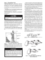
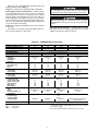
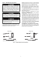
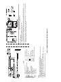
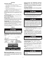
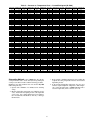
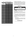
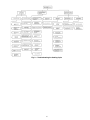
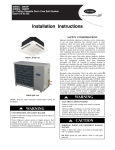
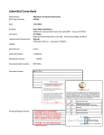
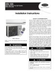
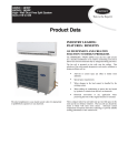
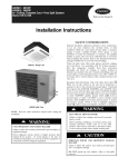
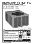
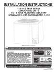
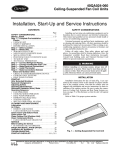
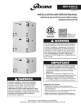
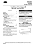
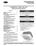
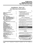
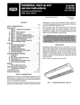
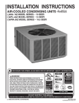
38HDF018-036
Duct Free Condensing Units
38HDR018-060
Ducted Condensing Units
Installation, Start-Up and
Service Instructions
CONTENTS
Page
SAFETY CONSIDERATIONS . . . . . . . . . . . . . . . . . . . . . . 1
INSTALLATION . . . . . . . . . . . . . . . . . . . . . . . . . . . . . . . . 1-10
Step 1 — Complete Pre-Installation Checks . . . . . . 1
• UNPACK UNIT
• INSPECT SHIPMENT
• CONSIDER SYSTEM REQUIREMENTS
• MATCHING THE CONDENSING UNIT TO AN
INDOOR UNIT
Step 2 — Rig and Mount Unit. . . . . . . . . . . . . . . . . . . . . 3
• MOUNTING ON GROUND
• MOUNTING ON ROOF
• RIGGING
Step 3 — Complete Refrigerant Piping
Connections . . . . . . . . . . . . . . . . . . . . . . . . . . . . . . . . . . . 3
• CHECK ACCURATER CONTROL
• FILTER DRIER
• MAKE PIPING SWEAT CONNECTORS
• PROVIDE SAFETY RELIEF
Step 4 — Make Electrical Connections . . . . . . . . . . . 6
• CONTROL CIRCUIT WIRING
• POWER WIRING
• CONNECTIONS TO DUCT-FREE FAN COIL UNITS
START-UP . . . . . . . . . . . . . . . . . . . . . . . . . . . . . . . . . . . . . . . 11
SERVICE . . . . . . . . . . . . . . . . . . . . . . . . . . . . . . . . . . . . . 11-14
MAINTENANCE . . . . . . . . . . . . . . . . . . . . . . . . . . . . . . . . . 14
TROUBLESHOOTING. . . . . . . . . . . . . . . . . . . . . . . . . .14,15
Puron® (R-410A) refrigerant systems operate at higher
pressures than standard R-22 systems. Do not use R-22 service equipment or components on Puron refrigerant equipment. If service equipment is not rated for Puron refrigerant,
equipment damage or personal injury may result.
INSTALLATION
Step 1 — Complete Pre-Installation Checks
UNPACK UNIT (See Fig. 1) — Move the unit to final location. Remove unit from carton, being careful not to damage
service valves and grilles.
SAFETY CONSIDERATIONS
Installing and servicing air conditioning equipment can be
hazardous due to system pressure and electrical components.
Only trained and qualified service personnel should install or
service air conditioning equipment.
Untrained personnel can perform basic maintenance, such
as cleaning and replacing filters. All other operations should be
performed by trained service personnel. When working on air
conditioning equipment, observe safety precautions in literature, tags, and labels attached to unit.
Follow all safety codes. Wear safety glasses and work
gloves. Use quenching cloth for brazing operations. Have fire
extinguisher available. Read these instructions thoroughly.
Consult local building codes and the National Electrical Code
(NEC) for special installation requirements.
Before installing or servicing system, always turn off main
power to system. There may be more than one disconnect
switch. Turn off accessory heater power if applicable. Electrical shock can cause serious personal injury.
Fig. 1 — 38HDF,HDR Unit
INSPECT SHIPMENT — File a claim with the shipping
company if shipment is damaged or incomplete. Check unit
nameplate to ensure unit matches job requirements.
CONSIDER SYSTEM REQUIREMENTS — Consult local
building codes and NEC for special installation requirements.
Allow sufficient space for airflow clearance, wiring, refrigerant piping, and servicing unit. See Fig. 2.
Locate unit so that condenser airflow is unrestricted on both
sides. Refer to Fig. 2.
Unit may be mounted on a level pad directly on base legs or
mounted on raised pads at support points. See Fig. 2 for center
of gravity.
MATCHING THE CONDENSING UNIT TO AN
INDOOR UNIT — The 38HDF,HDR units can be matched to
a corresponding indoor unit. The 38HDF018-036 units can be
matched with an in-ceiling cassette or high wall indoor unit.
The 38HDR unit can be matched with under-ceiling and residential fan coils. Refer to separate indoor unit literature for
more information.
Manufacturer reserves the right to discontinue, or change at any time, specifications or designs without notice and without incurring obligations.
Catalog No. 02-38HD0001-SI
Printed in U.S.A.
Form 38HD-4SI
Pg 1
1-06
Replaces: 38HDC-3SI
Book 1 4
Tab 3e 2f
2
024
030,036
048,060
024,030
036
—
1.6
1.0
0.6
0
CHASSIS
SIZE
(Reference)
B
3′-015/16″
(938.2)
3′-015/16″
(938.2)
3′-89/16″
(1131.9)
3′-89/16″
(1131.9)
A
2′-11/8″
(638.2)
2′-71/8″
(790.6)
3′-13/16″
(944.6)
3′-73/16″
(1097)
C
1′-29/16″
(369.9)
1′-51/16″
(433.4)
1′-51/16″
(433.4)
1′-29/16″
(369.9)
NOTE: Dimensions shown in feet-inches. Dimensions in ( ) are millimeters.
018
018
UNIT MODELS
38HDF
38HDR
Unit Size
Unit Size
1′-4″
(406.4)
1′-67/16″
(468.3)
1′-67/16″
(468.3)
1′-4″
(406.4)
D
1′-53/16″
(436.6)
1′-75/8″
(498.5)
1′-75/8″
(498.5)
1′-53/16″
(436.6)
F
1′-111/8″
(587.4)
2′-53/16″
(741)
2′-113/16″
(893.4)
1′-51/8″
(435)
G
1′-2″
(355.6)
1′-111/16″
(347.7)
1′-21/2″
(354.2)
1′-1″
(330.2)
J
0′-63/4″
(171.5)
0′-81/8″
(206.4)
0′-81/2″
(215.9)
0′-65/8″
(168.3)
K
0′-115/8″
(295.3)
1′-37/8″
(403.2)
1′-67/8″
(479.4)
0′-111/4″
(285.8)
L
(FIELD PROVIDED AND INSTALLED)
2′-4″
(711.5)
2′-101/16″
(865.5)
3′-41/16″
(1017.9)
1′-10″
(559.1)
H
Fig. 2 — 38HDF,HDR Unit Dimensions
1′-117/16″
(595.3)
2′-61/2″
(774.7)
2′-61/2″
(774.7)
1′-117/16″
(595.3)
E
0′-215/16″
(75)
0′-37/16″
(88)
0′-37/16″
(88)
0′-215/16″
(75)
N
8
8
7/
7/
048
060
M
22.22
22.22
19.05
19.05
15.88
15.88
19.05
19.05
15.88
mm
15.88
306
278
250
187
176
166
250
187
176
138.8
126.1
113.4
84.8
79.8
75.8
113.4
84.8
79.8
OPERATING WT
lb
kg
166
75.3
MINIMUM MOUNTING PAD
DIMENSIONS
Support Feet
ft-in.
mm
1′-11″ x 3′-6″
584.2 x 1066.8
2′-0″ x 4′-2″
609.6 x 1270
4
3/
8
5/
024
036
8
5/
018
4
4
3/
036
3/
4
3/
030
8
5/
030
in.
5/
8
024
018
CHASSIS SIZES 0 & .6
CHASSIS SIZES 1 & 1.6
UNIT SIZE
38HDR
38HDF
UNIT SIZE
3. Center of Gravity
.
NOTES:
1. Required clearances: with coil facing wall, allow 6 in. minimum clearance
on coil side and coil end, and 3 feet minimum clearance on compressor
end and fan side. With fan facing wall, allow 8 in. minimum clearance on
fan side and coil end, and 3 feet minimum clearance on compressor end
and coil side. With multi-unit application, arrange units so discharge of one
does not enter inlet of another.
2. Dimensions in parenthesis are in millimeters.
0′-6″
(152.4)
0′-61/2″
(165.4)
0′-61/2″
(165.4)
0′-6″
(152.4)
P
Step 2 — Rig and Mount Unit
When more than 50 ft of interconnecting tubing and more
than 30 ft of vertical lift is used, consult the residential long line
application instruction guide. For long-line applications, interconnecting lines over 100 ft must be installed with a liquid line
solenoid. A liquid line solenoid may also be installed on some
units to improve part-load efficiency. Refer to the ARI (Air
Conditioning & Refrigeration Institute) Directory.
If either refrigerant tubing or indoor coil is exposed to
the atmosphere, the system must be evacuated following good
refrigeration practices.
Run refrigerant tubes as directly as possible, avoiding
unnecessary turns and bends. Suspend refrigerant tubes so they
do not damage insulation on vapor tube and do not transmit
vibration to structure. Also, when passing refrigerant tubes
through a wall, seal the opening so that vibration is not transmitted to structure. Leave some slack in refrigerant tubes between
structure and outdoor unit to absorb vibration. Refer to separate
indoor unit installation instructions for additional information.
CHECK ACCURATER CONTROL — The correct AccuRater (bypass type) refrigerant control is required for system
capacity optimization. An AccuRater device with fieldreplaceable piston (see Fig. 4) is supplied with the outdoor unit.
Refer to the AccuRater metering device table in separate
indoor unit installation instructions to determine the correct
AccuRater piston size required for the condenser/evaporator
system being installed.
Piston style as shown in Fig. 4 is shipped with the unit. Do
not interchange components between the AccuRater device
types. Matching of outdoor unit with indoor unit may require
field replacement of piston. Replace piston, if required, before
connecting refrigerant lines. See Fig. 4. Piston replacement
instructions are included in the indoor unit installation instructions. After system installation is complete, see the Refrigerant
Charging section on page 12 to check and/or adjust refrigerant
charge.
FILTER DRIER — The filter drier must be replaced whenever the refrigeration system is exposed to the atmosphere. See
Fig. 4 for filter drier installation.
MOUNTING ON GROUND — Mount unit on a solid, level
concrete pad. Position unit so water or ice from roof does not
fall directly onto unit. Accessory stacking kits can be used
when units are to be stacked. See installation instructions
provided with the accessory kit. Use field-provided snow stand
or ice rack where prolonged subfreezing temperatures or heavy
snow occurs.
If conditions or local codes require unit be fastened to a pad,
6 field-supplied tiedown bolts should be used and fastened
through slots provided in unit mounting feet.
MOUNTING ON ROOF — Mount unit on a level platform
or frame at least 6 in. above roof surface. Isolate unit and tubing from structure.
RIGGING
Be sure unit panels are securely in place prior to rigging.
Loose unit panels could result in equipment damage or personal injury.
Keep the unit upright and lift unit using a sling. Use cardboard or padding under the sling, and spreader bars to prevent
sling damage to the unit. See Fig. 3. See Fig. 2 for center of
gravity reference. Install the unit so that the coil does not face
into prevailing winds. If this is not possible and constant winds
above 25 mph are expected, use accessory wind baffle. See
installation instructions provided with the accessory kit.
NOTE: Accessory wind baffles should be used on all units
with accessory low ambient temperature control.
Field-fabricated snow or ice stands may be used to raise unit
when operation will be required during winter months. Units
may also be wall mounted using the accessory wall-mounting
kit.
NOTE: Arrow on AccuRater body points in free flow direction, away from the
indoor coil.
Fig. 3 — Lifting Unit with Sling
Step 3 — Complete Refrigerant Piping Connections — Outdoor units may be connected to indoor
units using field-supplied tubing of refrigerant grade and condition. See Tables 1A and 1B for correct line sizes. Do not use
less than 10 ft of interconnecting tubing.
38HDF018-036
DO NOT BURY MORE THAN 36 IN. OF REFRIGERANT PIPE IN THE GROUND. If any section of pipe is
buried, there must be a 6-in. vertical rise to the valve
connections on the outdoor unit. If more than the
recommended length is buried refrigerant may migrate to
cooler, buried section during extended periods of system
shutdown. This causes refrigerant slugging and could
possibly damage the compressor at start-up.
38HDR018-060
Fig. 4 — AccuRater (Bypass Type) Metering
Device Components
3
Only use factory specified liquid-line filter driers with rated
working pressures less than 600 psig.
NOTE: Do not install a suction-line filter drier in liquid line.
MAKE PIPING SWEAT CONNECTIONS — Remove plastic
caps from liquid and suction service valves. Use refrigerant
grade tubing. Service valves are closed from the factory and are
ready for brazing. After wrapping the service valve with a wet
cloth, the tubing set can be brazed to the service valve using either silver bearing or non-silver bearing brazing material. Consult local code requirements. Refrigerant tubing and the indoor
coil are now ready for leak testing.
NOTE: Unit is shipped with R-410A factory charge indicated
on nameplate.
Pass nitrogen or other inert gas through piping while brazing to prevent formation of copper oxide.
To avoid damage while brazing, service valves should be
wrapped with a heat-sinking material such as a wet cloth.
When brazing tubing sets to the service valves, a brazing
shield MUST be used to prevent damage to the painted unit
surface.
PROVIDE SAFETY RELIEF — A fusible plug is located in
unit suction line; do not cap this plug. If local code requires
additional safety devices, install as directed.
Table 1A — 38HDF018-036 Physical Data
UNIT 38HDF
NOMINAL CAPACITY (Tons)
OPERATING WEIGHT (lb)
REFRIGERANT TYPE
METERING DEVICE
CHARGE (lb)*
OUTDOOR FAN
Rpm/Cfm
Diameter (in.)
No. Blades
Motor (hp)
OUTDOOR COIL
Face Area (sq ft)
No. Rows
FPI
HIGH PRESSURE SWITCH
Cut-In (psig)
Cutout (psig)
LOW PRESSURE SWITCH
Cut-In (psig)
Cutout (psig)
REFRIGERANT LINES
Connection Type
Liquid Line (in.) OD
Vapor Line (in.) OD
Max Length (ft)
Max Lift (ft)
Max Drop (ft)
COMPRESSOR
Type
Model
Oil Charge (POE - oz)
Accumulator
CONTROLS
Fusible Plug (F)
Control Voltage†
System Voltage
018
1.5
166
4.8
024
2.0
176
030
2.50
187
R-410A
AccuRater (Located at Fan Coil)
5.3
5.0
036
3.0
250
7.1
840/1720
18
3
1/
8
840/1720
18
3
1/
8
840/1720
18
3
1/
8
850/1720
24
3
1/
4
5.82
2
20
7.27
3
20
7.27
3
20
12.1
2
20
420 ± 25
650 ± 10
420 ± 25
650 ± 10
420 ± 25
650 ± 10
420 ± 25
650 ± 10
45 ± 25
20 ± 5
45 ± 25
20 ± 5
45 ± 25
20 ± 5
45 ± 25
20 ± 5
3/
8
5/
8
3/
8
5/
8
Sweat
3/
8
3/
4
3/
8
3/
4
200
65
150
200
65
150
200
65
150
200
65
150
ZP16K5E-PFV
25.0
ZP21K5E-PFV
25.0
Scroll
ZP25K5E-PFV
25.0
Yes
ZP34K5P-PFV
42.0
210
24 vac
208/230 v
208/230 v
FINISH
208/230 v
208/230 v, Single and 3 Phase,
460 v, 3 Phase
Gray
LEGEND
FPI — Fins Per Inch
POE — Polyol Ester
*Unit shipped with full factory charge. See ARI (Air Conditioning and
Refrigeration Institute) capacity table for proper charge and piston
for each fan coil type.
†24 v and a minimum of 40 va is provided in the fan coil unit.
4
Table 1B — 38HDR018-060 Physical Data
UNIT 38HDR
NOMINAL CAPACITY (Tons)
OPERATING WEIGHT (lb)
REFRIGERANT TYPE
METERING DEVICE
CHARGE (lb)*
OUTDOOR FAN
Rpm/Cfm
Diameter (in.)
No. Blades
Motor (hp)
OUTDOOR COIL
Face Area (sq ft)
No. Rows
FPI
HIGH PRESSURE SWITCH
Cut-In (psig)
Cutout (psig)
LOW PRESSURE SWITCH
Cut-In (psig)
Cutout (psig)
REFRIGERANT LINES
Connection Type
Liquid Line (in.) OD
Vapor Line (in.) OD
Max Length (ft)
Max Lift (ft)
Max Drop (ft)
COMPRESSOR
Type
Model
Oil Charge (POE - oz)
Crankcase Heater (watts)
Accumulator
CONTROLS
Fusible Plug (F)
Control Voltage**
System Voltage
FINISH
018
1.5
166
024
2.0
176
030
2.50
250
036
3.0
250
R-410A
AccuRater (Located at Fan Coil)
10.0
8.9
048
4.0
278
060
5.0
306
12.0
12.2
6.3
6.5
840/1720
18
3
1/
8
840/1720
18
3
1/
8
850/3900
24
3
1/
4
850/3900
18
3
1/
4
850/3900
24
3
1/
4
850/3900
24
3
1/
4
5.8
2
20
7.3
3
20
12.1
2
20
12.1
2
20
14.1
3
20
14.1
3
20
420 ± 25
650 ± 10
420 ± 25
650 ± 10
420 ± 25
650 ± 10
420 ± 25
650 ± 10
420 ± 25
650 ± 10
420 ± 25
650 ± 10
45 ± 25
20 ± 5
45 ± 25
20 ± 5
45 ± 25
20 ± 5
45 ± 25
20 ± 5
45 ± 25
20 ± 5
45 ± 25
20 ± 5
3/
8
5/
8
3/
8
5/
8
3/
8
3/
4
3/
8
3/
4
3/
8
7/
8
3/
8
7/ †
8
Sweat
200
65
150
ZP16K5E-PFV
25.0
—
208/230 v
200
65
150
200
65
150
200
65
150
200
65
150
Scroll
ZP21K5E-PFV ZP25K5E-PFV ZPZ9K5E-PFV ZP42K5E-PFV
25.0
25.0
25.0
42.0
—
40
40
40
Yes
208/230 v
LEGEND
FPI — Fins Per Inch
POE — Polyol Ester
200
65
150
ZP51K5E-PFV
42.0
40
210
24 vac
208/230 v
208/230 v, Single and 3 Phase, 460 v, 3 Phase
Gray
*Unit shipped with full factory charge. See ARI (Air Conditioning
and Refrigeration Institute) capacity table for proper charge and
piston for each fan coil type.
†Valve connection size is 7/8 inch. Recommended line size is
11/8 inches.
**24 v and a minimum of 40 va is provided in the fan coil unit.
5
Step 4 — Make Electrical Connections
NOTE: For wire runs up to 50 ft, use no. 18 AWG (American
Wire Gage) insulated wire. For 50 to 75 ft, use no. 16 AWG
insulated wire. For over 75 ft, use 14 AWG insulated wire.
NOTE: All wiring must conform to NEC and local codes.
NOTE: Operating unit on improper line voltage constitutes
abuse and could affect Carrier warranty. See Tables 2 and 3.
Do not install unit in a system where voltage may fluctuate
above or below permissible limits.
See Tables 2 and 3 for recommended fuse sizes. When making electrical connections, provide clearance at the unit for refrigerant piping connections.
NOTE: The 38HDF units are supplied with a 24-v control
transformer. The 38HDR units use the control transformer
supplied with the matched indoor unit.
POWER WIRING — Unit is factory wired for voltage shown
on nameplate. Provide adequate, fused disconnect switch
within sight from unit, readily accessible, but out of reach of
children. Provision for locking the switch open (off) is advisable to prevent power from being turned on while unit is being
serviced. Disconnect switch, fuses, and field wiring must
comply with the NEC and local code requirements. Use copper
wire only between the disconnect switch and unit. Use
minimum 60 C wire for the field power connection.
Route power wires through the opening in unit side panel
and connect in the unit control box as shown on the unit label
diagram and Fig. 6 and 7. Unit must be grounded.
CONNECTIONS TO DUCT-FREE FAN COIL UNITS —
The 38HDR units are designed for easy match-up to 40QA
duct free fan coils. This unit provides 24 v power for the outdoor unit from the fan coil. Connect the Y and C terminals of
the indoor unit to the Y and C terminals.
Unit cabinet must have an uninterrupted, unbroken electrical ground to minimize the possibility of personal injury if
an electrical fault should occur. This ground may consist of
electrical wire connected to unit ground lug in control compartment, or conduit approved for electrical ground when
installed in accordance with NEC, and local electrical
codes. Failure to follow this warning could result in the
installer being liable for the personal injury of others.
Unit failure as a result of operation on improper line
voltage or excessive phase imbalance constitutes abuse and
may cause damage to electrical components. Such operation would invalidate any applicable Carrier warranty.
Before performing service or maintenance, be sure indoor
unit main power switch is turned OFF and indoor blower
has stopped. Failure to do so may result in electrical shock
or injury from rotating fan blades.
CONTROL CIRCUIT WIRING — Control voltage is 24 v
(40 va minimum). See Fig. 5 and unit label diagram for fieldsupplied wiring details. Route control wire through opening in
unit side panel to connection in unit control box.
38HDR UNITS
38HDF UNITS
NOTE: For more information see schematic inside unit.
Fig. 5 — Typical Control Circuit Connections
6
Table 2 — 38HDF Electrical Data
38HDF
UNIT SIZE
018
024
030
208/230-1-60
208/230-1-60
208/230-1-60
208/230-1-60
208/230-3-60
460-3-60
036
FLA
HACR
LRA
NEC
RLA
—
—
—
—
—
V-PH-Hz
VOLTAGE RANGE*
Min
Max
187
253
187
253
187
253
187
253
187
253
414
506
COMPRESSOR
RLA
LRA
10.0
48.0
14.3
58.3
15.7
73.0
20.0
112.0
14.7
88.0
6.6
44.0
FUSE/HACR
BKR AMPS
13.3
18.7
20.4
26.5
19.8
9.1
20
30
35
45
30
15
Maximum deviation is 7 v.
Determine percentage of voltage imbalance:
*Permissible limits of the voltage range at which unit will operate
satisfactorily.
NOTES:
1. Control circuit is 24 v on all units and requires an external power
source.
2. All motors and compressors contain internal overload protection.
3. In compliance with NEC (U.S.A. Standard) requirements for multimotor and combination load equipment (refer to NEC Articles
430 and 440), the overcurrent protective device for the unit shall
be fuse or HACR breaker.
4. Motor RLA values are established in accordance with UL (Underwriters’ Laboratories) Standard 465 (U.S.A. Standard).
5. 38HDF,HDR018-030 units are only available in single-phase
voltage.
6. Unbalanced 3-Phase Supply Voltage
Never operate a motor where a phase imbalance in supply voltage is greater than 2%. Use the following formula to determine
the percentage of voltage imbalance:
% Voltage Imbalance = 100 x
7
457
= 1.53%
This amount of phase imbalance is satisfactory as it is below the
maximum allowable of 2%.
IMPORTANT: Contact your local electric utility company immediately if the supply voltage phase imbalance is more than 2%.
max voltage deviation from average voltage
average voltage
EXAMPLE: Supply voltage is 460-3-60.
AB = 452 v
BC = 464 v
AC = 455 v
Average Voltage =
MIN CKT
AMPS
Determine maximum deviation from average voltage:
(AB) 457 – 452 = 5 v
(BC) 464 – 457 = 7 v
(AC) 457 – 455 = 2 v
LEGEND
Full Load Amps
Heating, Air Conditioning, Refrigeration
Locked Rotor Amps
National Electrical Code
Rated Load Amps (Compressor)
= 100 x
OUTDOOR FAN MOTOR
FLA
NEC Hp
kW Out
0.80
0.125
0.09
0.80
0.125
0.09
0.80
0.125
0.09
1.45
0.25
0.19
1.45
0.25
0.19
0.80
0.25
0.19
452 + 464 + 455
3
1371
3
= 457
=
7
Table 3 — 38HDR Electrical Data
38HDR
UNIT SIZE
018
024
030
208/230-1-60
208/230-1-60
208/230-1-60
208/230-1-60
208/230-3-60
460-3-60
208/230-1-60
208/230-3-60
460-3-60
208/230-1-60
208/230-3-60
460-3-60
036
048
060
FLA
HACR
LRA
NEC
RLA
—
—
—
—
—
V-PH-Hz
VOLTAGE RANGE*
Min
Max
187
253
187
253
187
253
187
253
187
253
414
506
187
253
187
253
414
506
187
253
187
253
414
506
COMPRESSOR
RLA
LRA
10.0
48.0
14.3
58.3
15.7
64.0
15.7
77.0
10.4
88.0
6.3
38.0
24.3
117.0
15.6
83.1
6.9
41.0
29.4
134.0
17.8
110.0
8.6
52.0
FUSE/HACR
BKR AMPS
13.3
18.7
21.1
21.1
14.5
8.7
31.8
21.0
9.4
38.2
23.7
11.6
20
30
35
35
20
15
55
35
15
65
40
20
Maximum deviation is 7 v.
Determine percentage of voltage imbalance:
*Permissible limits of the voltage range at which unit will operate
satisfactorily.
NOTES:
1. Control circuit is 24 v on all units and requires an external power
source.
2. All motors and compressors contain internal overload protection.
3. In compliance with NEC (U.S.A. Standard) requirements for multimotor and combination load equipment (refer to NEC Articles
430 and 440), the overcurrent protective device for the unit shall
be fuse or HACR breaker.
4. Motor RLA values are established in accordance with UL (Underwriters’ Laboratories) Standard 465 (U.S.A. Standard).
5. 38HDF,HDR018-030 units are only available in single-phase
voltage.
6. Unbalanced 3-Phase Supply Voltage
Never operate a motor where a phase imbalance in supply voltage is greater than 2%. Use the following formula to determine
the percentage of voltage imbalance:
% Voltage Imbalance = 100 x
7
457
= 1.53%
This amount of phase imbalance is satisfactory as it is below the
maximum allowable of 2%
IMPORTANT: Contact your local electric utility company immediately if the supply voltage phase imbalance is more than 2%.
max voltage deviation from average voltage
average voltage
EXAMPLE: Supply voltage is 460-3-60.
AB = 452 v
BC = 464 v
AC = 455 v
Average Voltage =
MIN CKT
AMPS
Determine maximum deviation from average voltage:
(AB) 457 – 452 = 5 v
(BC) 464 – 457 = 7 v
(AC) 457 – 455 = 2 v
LEGEND
Full Load Amps
Heating, Air Conditioning, Refrigeration
Locked Rotor Amps
National Electrical Code
Rated Load Amps (Compressor)
= 100 x
OUTDOOR FAN MOTOR
FLA
NEC Hp
kW Out
0.80
0.125
0.09
0.80
0.125
0.09
1.45
0.25
0.19
1.45
0.25
0.19
1.45
0.25
0.19
0.80
0.25
0.19
1.45
0.25
0.19
1.45
0.25
0.19
0.80
0.25
0.19
1.45
0.25
0.19
1.45
0.25
0.19
0.80
0.25
0.19
452 + 464 + 455
3
1371
3
= 457
=
8
9
LEGEND
Splice (Field)
Contactor, Compressor
Capacitor
Crankcase Heater Thermostat
Crankcase Heater
Compressor Motor
Equipment
Ground
High-Pressure Switch
Low-Pressure Switch
Outdoor-Fan Motor
Overload
Terminal Board
Transformer
Optional or Accessory Wire
Factory Wiring
Field Control Wiring
Field Power Wiring
Splice
Terminal Block
Terminal (Unmarked)
Terminal (Marked)
Fig. 6 — 38HDF018-036 Typical Wiring Schematic
NOTES:
1. Compressor and fan motors are thermally protected.
2. Wire in accordance with National Electrical Code (NEC) and local codes. Replace
any original wires with 90° C wire or its equivalent.
3. Use minimum 60° C wire for field power wiring.
4. Transformer has internal 4.5A thermal fuse on the primary side.
5. Transformer factory wired for 230 v. For 208 v move black wire to 208 volt tap on
transformer.
6. Crankcase heater and thermostat used on selected models only.
C
—
CAP —
CCHT —
CH
—
COMP —
EQUIP —
GND —
HPS —
LPS —
OFM —
OL
—
TB
—
TRAN —
38HDF OPERATION SEQUENCE
CALL FOR COOLING:
1. Control voltage from transformer to thermostat (24 v).
2. At thermostat 24 v is switched to “G” and “Y.”
3. 24 v from thermostat “G” energizes fan relay at indoor fan coil unit and indoor-fan motor runs.
4. 24 v from thermostat “Y” energizes the contactor coil and the compressor and outdoor-fan motor will both
run.
6. If the internal protection of the compressor or LPS or HPS open, the 24 v to contactor coil will be interrupted. The compressor and outdoor-fan motor will stop.
10
LEGEND
Factory Wiring
Field Control Wiring
Field Power Wiring
Splice
Terminal Block
Terminal (Unmarked)
Terminal (Marked)
Splice (Field)
Fig. 7 — 38HDR018-060 Typical Wiring Schematic
NOTES:
1. Compressor and fan motors are thermally protected.
2. Wire in accordance with National Electrical Code (NEC) and local codes. Replace
any original wires with 90° C wire or its equivalent.
3. The CLO locks out the COMP to prevent short cycling on COMP overloads and
safety devices. Before replacing CLO check these devices.
4. If indoor section has a transformer with a grounded secondary, connect the
grounded side to “C” on the low voltage board.
5. Use minimum 60° C wire for field power wiring.
6. Crankcase heater and thermostat used on selected models only.
C
— Contactor, Compressor
CAP
— Capacitor
CCHT — Crankcase Heater
Thermostat
CH
— Crankcase Heater
CLO
— Compressor Lockout
COMP — Compressor Motor
CT
— Current Transformer
EQUIP — Equipment
GND
— Ground
HPS
— High-Pressure Switch
LPS
— Low-Pressure Switch
OFM
— Outdoor-Fan Motor
OL
— Overload
TB
— Terminal Board
38HDR OPERATION SEQUENCE
CALL FOR COOLING:
1. Control voltage from transformer to thermostat (24 v).
2. At thermostat 24 v is switched to “G” and “Y.”
3. 24 v from thermostat “G” energizes fan relay at indoor fan coil and indoor-fan motor runs.
4. 24 v from thermostat “Y” energizes the logic in the CLO, and the contactor coil, both at the outdoor unit.
Compressor and outdoor-fan motor run.
6. If the internal protector of the compressor, HPS, or LPS open, the 24 v to the contactor coil will be interrupted, the compressor and outdoor-fan motor will stop, and the CLO will keep the circuit open until reset
by stopping and restarting the 24 v power at the thermostat.
START-UP
Preliminary Checks
Internal Current and Temperature Sensitive
Overload — The control resets automatically when
internal compressor motor temperature drops to a safe level
(overloads may require up to 45 minutes to reset). When an
internal overload is suspected of being open, check by using an
ohmmeter or continuity tester.
1. Check that all internal wiring connections are tight and
that all barriers, covers, and panels are in place.
2. Field electrical power source must agree with unit nameplate rating.
3. All service valves must be open.
4. Belly-band crankcase heater must be tight on compressor
crankcase for those units with belly-band heaters.
Leak Test — Field piping and fan coil must be leak tested
by pressure method. Use R-410A at approximately 25 psig
backed up with an inert gas to a total pressure not to exceed
245 psig.
Leak detectors should be designed to detect HFC (hydrofluorocarbon) refrigerant.
Evacuate and Dehydrate — Field piping and fan coil
must be evacuated and dehydrated.
Charge System — Release charge into system by opening (backseating) liquid and suction line service valves. Refer
to separate indoor unit installation instructions for the required
total system charge when connected to 25 ft of tubing.
To Start Unit — Be sure that the field disconnect is
closed. Set room thermostat below ambient temperature. Operate unit for 15 minutes, then check system refrigerant charge.
See Refrigerant Charging section on page 12.
NOTE: When using in conjunction with 40QA or 40QK fan
coils, refer to start-up instructions included with fan coil for
correct start-up procedures.
Pumpdown Procedure — The system may be pumped
down in order to make repairs on the low side without losing
complete refrigerant charge.
Never open system to atmosphere while it is under a vacuum. Equipment damage may result.
When system must be opened for service, recover refrigerant, break vacuum with dry nitrogen before opening system.
1. Attach pressure gage to suction service valve gage port.
2. Frontseat the liquid/mixed phase line valve.
The 38HDC unit coils hold only the factory-designated
amount of refrigerant. Additional refrigerant may cause
units to relieve pressure through the compressor internal
pressure relief valve (indicated by a sudden rise of suction
pressure) before suction pressure reaches 5 psig. If this
occurs, shut off unit immediately then frontseat the suction
valve and remove and recover excess refrigerant following
accepted practices. Equipment damage may result.
3. Start unit and run until suction pressure reaches 20 psig.
4. Shut unit off and frontseat suction valve.
5. Depressurize low side of unit and recover refrigerant
following accepted practices.
SERVICE
Before performing recommended maintenance, be sure
unit main power switch is turned off. Failure to do so may
result in electrical shock or injury from rotating fan blade.
High-Pressure Switch — The high-pressure switch,
located on discharge line, protects against high discharge
pressures caused by such events as overcharge, condenser-fan
motor failure, system restriction, etc. It opens on pressure rise at
about 650 ± 10 psig. If system pressures go above this setting
during abnormal conditions, the switch opens.
Outdoor Fan — A reinforced wire mount holds the outdoor fan assembly in position. See Fig. 8 for proper mounting
position.
DO NOT attempt to simulate these system abnormalities
— high pressures pose a serious safety hazard.
The high-pressure switch is checked with an ohmmeter. If
system pressure is below 625 psig switch shows continuity.
Crankcase Heater — The crankcase heater prevents
refrigerant migration and compressor oil dilution during
shutdown when compressor is not operating. If the crankcase
heater is deenergized for more than 6 hours, both compressor
service valves must be closed.
NOTE: Crankcase heaters are only available on 38HDR030060 units.
The crankcase heater is powered by the high-voltage power
of the unit. It is connected across the line side of the contactor
and is thermostatically controlled.
38HDF UNIT SIZE, in.
018-030
036
0.433
0
018,024
0.433
38HDR UNIT SIZE, in.
030,036
0
048,060
0
Fig. 8 — Condenser-Fan Mounting Positions
Use extreme caution when troubleshooting this device, as
line voltage is continually present. Serious personal injury
could result.
High-Pressure Relief Valve — The high-pressure relief valve is located in the compressor. The relief valve opens at
a pressure differential of approximately 550 to 625 ± 50 psid
between suction (low side) and discharge (high side) to allow
pressure equalization.
11
All units are shipped with the refrigerant charge listed on
the nameplate. See indoor unit Installation Instructions for additional charge requirements.
NOTE: For 38HDF units only, charge to nameplate. See the
indoor unit owner’s manual for any additional charge
requirements.
Refer to Table 4 and consider the following when working
with Puron® refrigerant:
• Puron refrigerant cylinders are rose colored.
• Recovery cylinder service pressure rating must be
400 psig, DOT (Department of Transportation) 4BA400
or DOT BW400.
• Puron systems should be charged with liquid refrigerant.
Use a commercial type metering device in the manifold
hose when charging into suction line with compressor
operating.
• Manifold sets should be 700 psig high side and 180 psig
low side with 550 psig low-side retard.
• Use hoses with 700 psig service pressure rating.
• Puron refrigerant, as with other HFCs, is only compatible
with POE oils.
• Vacuum pumps will not remove moisture from oil.
• Polyol Ester oils absorb moisture rapidly. Do not expose
oil to atmosphere.
• Polyol Ester oils may cause damage to certain plastics
and roofing materials.
• Wrap all filter driers and service valves with wet cloth
when brazing.
• A factory approved, liquid-line filter drier is required on
every unit.
• Do not use a TXV (thermostatic expansion valve)
designed for use with R-22 refrigerant. Refer to separate
indoor unit installation instructions for more details.
• If using a suction line drier, do not leave in place for
more than 72 hours.
To troubleshoot:
1. Apply voltmeter across crankcase heater leads to see if
heater voltage is on. Do not touch heater. Carefully feel
area around crankcase heater; if warm, crankcase heater
is functioning.
2. With power off and heater leads disconnected, check
across leads with ohmmeter. Do not look for a specific resistance reading. Check for resistance or an open circuit,
and change heater if an open circuit is detected.
Service Valves — The service valves in the outdoor unit
come from the factory frontseated. This means the refrigerant
charge is isolated from the line-set connection ports. To prevent
damage to the valve, use a wet cloth or other accepted heat sink
material on the valve before brazing.
The service valve cannot be field repaired, therefore, only a
complete valve or valve stem seal and service port caps are
available for replacement.
Refrigerant Charging
To prevent personal injury, wear safety glasses and gloves
when handling refrigerant. Do not overcharge system —
this can cause compressor flooding.
Service valves must be fully backseated to close service
port. There is no Schrader valve at the service port, and
failure to backseat the valve could result in loss of system
charge or personal injury.
NOTE: Do not vent or depressurize unit refrigerant to atmosphere. Remove and recover refrigerant following accepted
practices.
12
Table 4 — Pressure vs. Temperature Chart — Puron® Refrigerant (R-410A)
PRESSURE TEMPERATURE PRESSURE TEMPERATURE PRESSURE TEMPERATURE PRESSURE TEMPERATURE PRESSURE TEMPERATURE PRESSURE TEMPERATURE
PSIG
°F
PSIG
°F
PSIG
°F
PSIG
°F
PSIG
°F
PSIG
°F
12
–37.7
114
37.8
216
74.3
318
100.2
420
120.7
522
137.6
14
–34.7
116
38.7
218
74.9
320
100.7
422
121.0
524
137.9
16
–32.0
118
39.5
220
75.5
322
101.1
424
121.4
526
138.3
18
–29.4
120
40.5
222
76.1
324
101.6
426
121.7
528
138.6
20
–26.9
122
41.3
224
76.7
326
102.0
428
122.1
530
138.9
22
–24.5
124
42.2
226
77.2
328
102.4
430
122.5
532
139.2
24
–22.2
126
43.0
228
77.8
330
102.9
432
122.8
534
139.5
26
–20.0
128
43.8
230
78.4
332
103.3
434
123.2
536
139.8
28
–17.9
130
44.7
232
78.9
334
103.7
436
123.5
538
140.1
30
–15.8
132
45.5
234
79.5
336
104.2
438
123.9
540
140.4
32
–13.8
134
46.3
236
80.0
338
104.6
440
124.2
544
141.0
34
–11.9
136
47.1
238
80.6
340
105.1
442
124.6
548
141.6
36
–10.1
138
47.9
240
81.1
342
105.4
444
124.9
552
142.1
38
–8.3
140
48.7
242
81.6
344
105.8
446
125.3
556
142.7
40
–6.5
142
49.5
244
82.2
346
106.3
448
125.6
560
143.3
42
–4.5
144
50.3
246
82.7
348
106.6
450
126.0
564
143.9
44
–3.2
146
51.1
248
83.3
350
107.1
452
126.3
568
144.5
46
–1.6
148
51.8
250
83.8
352
107.5
454
126.6
572
145.0
48
0.0
150
52.5
252
84.3
354
107.9
456
127.0
576
145.6
50
1.5
152
53.3
254
84.8
356
108.3
458
127.3
580
146.2
52
3.0
154
54.0
256
85.4
358
108.8
460
127.7
584
146.7
54
4.5
156
54.8
258
85.9
360
109.2
462
128.0
588
147.3
56
5.9
158
55.5
260
86.4
362
109.6
464
128.3
592
147.9
58
7.3
160
56.2
262
86.9
364
110.0
466
128.7
596
148.4
60
8.6
162
57.0
264
87.4
366
110.4
468
129.0
600
149.0
62
10.0
164
57.7
266
87.9
368
110.8
470
129.3
604
149.5
64
11.3
166
58.4
268
88.4
370
111.2
472
129.7
608
150.1
66
12.6
168
59.0
270
88.9
372
111.6
474
130.0
612
150.6
68
13.8
170
59.8
272
89.4
374
112.0
476
130.3
616
151.2
70
15.1
172
60.5
274
89.9
376
112.4
478
130.7
620
151.7
72
16.3
174
61.1
276
90.4
378
112.6
480
131.0
624
152.3
74
17.5
176
61.8
278
90.9
380
113.1
482
131.3
628
152.8
76
18.7
178
62.5
280
91.4
382
113.5
484
131.6
632
153.4
78
19.8
180
63.1
282
91.9
384
113.9
486
132.0
636
153.9
80
21.0
182
63.8
284
92.4
386
114.3
488
132.3
640
154.5
82
22.1
184
64.5
286
92.8
388
114.7
490
132.6
644
155.0
84
23.2
186
65.1
288
93.3
390
115.0
492
132.9
648
155.5
86
24.3
188
65.8
290
93.8
392
115.5
494
133.3
652
156.1
88
25.4
190
66.4
292
94.3
394
115.8
496
133.6
656
156.6
90
26.4
192
67.0
294
94.8
396
116.2
498
133.9
660
157.1
92
27.4
194
67.7
296
95.2
398
116.6
500
134.0
664
157.7
94
28.5
196
68.3
298
95.7
400
117.0
502
134.5
668
158.2
96
29.5
198
68.9
300
96.2
402
117.3
504
134.8
672
158.7
98
30.5
200
69.5
302
96.6
404
117.7
506
135.2
676
159.2
100
31.2
202
70.1
304
97.1
406
118.1
508
135.5
680
159.8
102
32.2
204
70.7
306
97.5
408
118.5
510
135.8
684
160.3
104
33.2
206
71.4
308
98.0
410
118.8
512
136.1
688
160.8
106
34.1
208
72.0
310
98.4
412
119.2
514
136.4
692
161.3
108
35.1
210
72.6
312
98.9
414
119.6
516
136.7
696
161.8
110
35.5
212
73.2
314
99.3
416
119.9
518
137.0
112
36.9
214
73.8
316
99.7
418
120.3
520
137.3
Subcooling Method — For 38HDR units only, the sub-
3. Refer to Table 5. Find the temperature point at which the
required subcooling temperature intersects the measured
liquid line pressure.
4. If the measured liquid line temperature does not agree
with the required liquid line temperature, ADD refrigerant to lower the temperature, or REMOVE refrigerant to
raise the temperature (allow a tolerance of ±3° F).
cooling method is used to check and adjust charge during the
cooling season. Refer to Table 5 and the following procedure:
NOTE: For use with residential fan coils and the 40QA060
under ceiling unit only.
1. Operate unit a minimum of 15 minutes before checking
charge.
2. Measure liquid line temperature near liquid line service
valve, and measure the liquid pressure at the liquid line
service valve. Use a digital thermometer for all temperature measurements. DO NOT use mercury or dial-type
thermometers.
13
Table 5 — Subcooling Charging Table
LIQUID PRESSURE
AT SERVICE VALVE
(psig)
189
195
202
208
215
222
229
236
243
251
259
266
274
283
291
299
308
317
326
335
345
354
364
374
384
395
406
416
427
439
450
462
474
486
499
511
8
58
60
62
64
66
68
70
72
74
76
78
80
82
84
86
88
90
92
94
96
98
100
102
104
106
108
110
112
114
116
118
120
122
124
126
128
REQUIRED LIQUID LINE
TEMPERATURE (F)
Required Subcooling
Temperature (F)
10
12
14
16
56
54
52
50
58
56
54
52
60
58
56
54
62
60
58
56
64
62
60
58
66
64
62
60
68
66
64
62
70
68
66
64
72
70
68
66
74
72
70
68
76
74
72
70
78
76
74
72
80
78
76
74
82
80
78
76
84
82
80
78
86
84
82
80
88
86
84
82
90
88
86
84
92
90
88
86
94
92
90
88
96
94
92
90
98
96
94
92
100
98
96
94
102
100
98
96
104
102
100
98
106
104
102
100
108
106
104
102
110
108
106
104
112
110
108
106
114
112
110
108
116
114
112
110
118
116
114
112
120
118
116
114
122
120
118
116
124
122
120
118
126
124
122
120
Compressor Lockout Switch — The 38HDR units
are provided with a compressor lockout protective device. If
the compressor shuts down due to any safety device, a current
loop monitoring the compressor current senses no current flow.
The unit will lock out until the control power is interrupted to
reset the lockout. Determine the reason for the safety trip. To
restart, turn the thermostat to the OFF position and then set the
thermostat to an operating position.
18
48
50
52
54
56
58
60
62
64
66
68
70
72
74
76
78
80
82
84
86
88
90
92
94
96
98
100
102
104
106
108
110
112
114
116
118
MAINTENANCE
Before performing recommended maintenance, be sure
unit main power switch is turned off. Failure to do so may
result in electric shock or injury from rotating fan blade.
Lubrication
COMPRESSOR — Compressor contains factory oil charge;
replace oil when lost. Use Mobile 3MA-POE oil.
Cleaning Coils — Coil should be washed out with water
or blown out with compressor air. Note that the blow-thru
design causes dirt and debris to build up on the inside of the
coils.
Clean coil annually or as required by location and outdoor
air conditions. Inspect coil monthly and clean as required. Fins
are not continuous through coil sections. Dirt and debris may
pass through first section, become trapped between the row of
fins and restrict condenser airflow. Use a flashlight to determine if dirt or debris has collected between coil sections. Clean
coil as follows:
1. Turn off unit power.
2. Using a garden hose or other suitable equipment, flush
coil from the outside to remove dirt. Be sure to flush all
dirt and debris from drain holes in base of unit. Fan
motors are waterproof.
TROUBLESHOOTING
See Fig. 9 for troubleshooting information.
14
Fig. 9 — Troubleshooting the Cooling Cycle
15
Copyright 2006 Carrier Corporation
Manufacturer reserves the right to discontinue, or change at any time, specifications or designs without notice and without incurring obligations.
Catalog No. 02-38HD0001-SI
Printed in U.S.A.
Form 38HD-4SI
Pg 16
2-06A
1-06
Replaces: 38HDC-3SI
Book 1 4
Tab 3e 2f