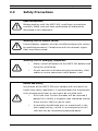
1
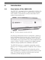
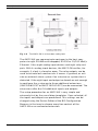
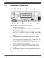
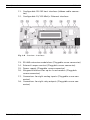
AMC2 4W
APC-AMC2-4W | APC-AMC2-4WCF | APC-AMC2-4WUS
en
Installation manual
AMC2 4W
| en
3
Remarks
This hardware is part of a security system. Access shall be limited to authorized persons only.
Some states do not allow the exclusion or limitation of implied
warranties, or limitation of liability for incidental or consequential damages, so the above limitation or exclusion might not
apply to you.
Bosch Security Systems retains all rights not expressly granted.
Nothing in this license constitutes a waiver of Bosch’s rights
under the U.S. Copyright laws or any other federal or state law.
If you have any questions concerning this license, please, write
to:
Bosch Access Systems GmbH
Adenauerstr. 20 / A3
D-52146 Würselen
Germany.
Bosch Security Systems
Installation manual
F.01U.024.965 | V.4 | 2006.09
4
en |
AMC2 4W
Table of Contents
1
Please read carefully
7
1.1
Explanation of Used Symbols
7
1.2
Internet
7
2
Safety Instructions
8
2.1
Important Safety Notes
8
2.2
FCC & ICES Information
10
2.3
Safety Precautions
11
2.4
Unpacking
12
3
Introduction
13
3.1
Description of the AMC2 4W
13
3.2
Equipment Configuration
15
3.3
Performance Characteristics
18
3.4
System Overview
19
4
Technical Data
20
5
Installing
22
5.1
Mounting
22
5.2
Demounting
23
5.3
Opening the AMC2 4W Case
24
5.4
Cabling
25
5.4.1
Conductor data for connection to power supply
25
5.4.2
Grounding and Shielding the Host Interface
26
5.4.3
Grounding and Shielding the Extension Interface
28
5.5
Connecting Power Supply
28
5.6
RS-485 Host Interface
30
5.6.1
RS-485 Two Wire Connection
32
5.6.2
RS-485 Four Wire Connection
33
5.6.3
DIL Switch Address Selector
34
5.7
RS-232 Host Interface
36
5.8
Ethernet Interface
37
F.01U.024.965 | V.4 | 2006.09
Installation manual
Bosch Security Systems
AMC2 4W
| en
5
5.9
RS-485 Extension Module Bus
5.10
Wiegand Interface for Card Readers
39
39
5.11
Connecting Relay Outputs
41
5.12
Connecting Analog Input Devices
44
5.13
Tamper Protection
46
6
Operating
48
6.1
Status Display of the AMC2 4W
48
6.2
Configuring the Ethernet Interface
50
6.3
Resetting the AMC2 4W
50
6.3.1
Resetting the Software
50
6.3.2
Resetting the Network Configurations
51
7
Appendix
53
7.1
Connecting Diagrams
53
7.2
Legend
57
8
Index
58
Bosch Security Systems
Installation manual
F.01U.024.965 | V.4 | 2006.09
6
en |
F.01U.024.965 | V.4 | 2006.09
AMC2 4W
Installation manual
Bosch Security Systems
AMC2 4W
Please read carefully | en
1
Please read carefully
1.1
Explanation of Used Symbols
7
Throughout this document, helpful tips, important notes, cautions and warnings will be presented for the reader to keep in
mind. These appear different from the rest of the text as follows:
!
CAUTION! or WARNING!
These warn the operator that damage to the program or equipment might occur.
NOTE!
i
1.2
Important Notes – must be followed for successful operation
and programming. Tips and shortcuts might also be included
here.
Internet
If you are interested in further information on this product or
information on other products, please, refer to our website at
http://www.bosch-security-systems.com.
Bosch Security Systems
Installation manual
F.01U.024.965 | V.4 | 2006.09
8
en | Safety Instructions
AMC2 4W
2
Safety Instructions
2.1
Important Safety Notes
1.
Read, Follow, and Retain Instructions - All safety and
operating instructions must be read and followed properly
before putting the unit into operation. Retain instructions
for future reference.
2.
Consider all Warnings - Adhere to all warnings on the unit
and in the operating instructions.
3.
Accessories - Use only accessories recommended by the
manufacturer or those sold with the product. Accessories
not recommended by the manufacturer shall not be used,
as they may cause hazards.
4.
Installation Precautions - Do not place this unit on an
unstable stand, tripod, bracket, or mount. The unit may
fall, causing serious injury to persons and damage to the
unit. Mount the unit according to the manufacturer’s
instructions.
5.
Service - Do not attempt to service this unit by yourself.
Opening or removing covers may expose you to dangerous
voltages or other hazards. Refer all servicing to qualified
service personnel.
6.
Damage Requiring Service - Disconnect the unit from the
main AC or DC power source and refer servicing to qualified service personnel under the following conditions:
•
•
When the power supply cord or plug is damaged.
If liquid has been spilled or an object has fallen into
the unit.
•
If the unit has been exposed to water and/or inclement weather (rain, snow, etc.).
•
If the unit does not operate normally, when following
the operating instructions. Adjust only those controls
specified in the operating instructions. Improper
adjustment of other controls may result in damage,
and require extensive work by a qualified technician
to restore the unit to normal operation.
F.01U.024.965 | V.4 | 2006.09
Installation manual
Bosch Security Systems
AMC2 4W
Safety Instructions | en
•
•
9
If the unit has been dropped or the cabinet damaged.
If the unit exhibits a distinct change in performance,
this indicates that service is needed.
7.
Replacement Parts - When replacement parts are
required, the service technician shall use replacement
parts that are specified by the manufacturer. Unauthorized
substitutions may result in fire, electrical shock or other
hazards.
8.
Safety Check - Upon completion of service or repair work
on the unit, ask the service technician to perform safety
checks to ensure that the unit operates properly
9.
Power Sources - Operate the unit only from the type of
power source indicated on the label. If unsure of the type
of power supply to use, contact your dealer
•
For units intended to operate from battery power,
refer to the operating instructions.
•
For units intended to operate with External Power
Supplies, use only the recommended approved power
supplies.
•
For units intended to operate with a limited power
source, this power source must comply with EN/UL
60950. Substitutions may damage the unit or cause
fire or shock.
•
For units intended to operate at 12/24V DC normal
input voltage is 12/24V DC. Voltages applied to the
unit’s power input shall not exceed 15/30V DC.
10. Lightning - For added protection during a lightning storm,
or when this unit is left unused for long periods of time,
disconnect the unit from power. This will prevent damage
to the unit due to lightning and excessive power line
surges.
11. Restricted Access Locations are required for the installation.
Bosch Security Systems
Installation manual
F.01U.024.965 | V.4 | 2006.09
10 en | Safety Instructions
2.2
AMC2 4W
FCC & ICES Information
This device complies with part 15 of the FCC rules. Operation is
subject to the following two conditions: (1) This device may not
cause harmful interference, and (2) this device must accept any
interference received, including interference that may cause
undesired operation.
This equipment has been tested and found to comply with the
limits for a Class B digital device, pursuant to part 15 of the
FCC rules. The limits are designed to provide reasonable protection against harmful interference in a residental installation.
This equipment generates, uses and can radiate radio frequency energy and, if not installed and used in accordance with
the instructions, may cause harmful interference to radio communications. However, there is no guarantee that interference
will not occur in a particular installation. If this equipment does
cause harmful interference to radio or television reception,
which can be determined by turning the equipment off and on,
the user is encouraged to try to correct the interference by one
or more of the following measures:
1.
2.
Reorient or relocare receiving antenna
Increase the separation between the equipment and the
receiver
3.
Connect the equipment into an outlet on a circuit different
4.
Consult the dealer or an experienced radio/TV technician
from that to which the receiver is connected
for help
F.01U.024.965 | V.4 | 2006.09
Installation manual
Bosch Security Systems
AMC2 4W
2.3
Safety Instructions | en 11
Safety Precautions
Read instructions!
!
Before working with the AMC2 4W, read these instructions
carefully. Make sure you have understood all information
described in this document.
Warning! Risk of electric shock!
!
External power supplies must be installed and put into service
by qualified personnel. Compliance with the relevant regulations must be ensured.
Warning! Risk of damaging equipment!
!
•
Always switch off power of the AMC2 4W before modifying the installation.
•
Do not connect or disconnect plug connectors, data
cables or screw connectors while power is on!
Health and Safety
Installation of the AMC2 4W must comply with any local fire,
health and safety regulations. A secured door that may be part
of an escape route from an area must be installed with:
!
•
A fail-safe lock. So that the door will be released if
power fails. Ideally, a magnetic lock should be used as
these are less likely to jam or seize.
•
A normally-closed break-glass or manual pull in the
lock supply wiring, so that in an emergency the failsafe lock can be immediately powered down.
Bosch Security Systems
Installation manual
F.01U.024.965 | V.4 | 2006.09
12 en | Safety Instructions
!
AMC2 4W
CAUTION!
Disconnect both AC and battery power supply before working
on the controller.
Warning! Risk of damage!
!
Protect the hardware from electrostatic discharge by observing
ESD instructions before unpacking or touching connectors or
electronics.
CAUTION: Lithium Battery
!
Danger of explosion if battery is replaced incorrectly. Replace
only with the same type as recommended by the manufacturer.
Dispose used batteries according to the battery manufacturer’s
instructions.
2.4
Unpacking
Check the packaging for visual damage. If anything has been
damaged during transport, make the transport agency aware of
this.
Carefully unpack the unit. This is an electronic device that must
be handled with care to avoid damage. Do not attempt to put
the unit into operation if components are damaged.
If parts are missing, inform your customer service representative or a Bosch Security Systems salesperson. The shipping carton is the safest transport container for the unit. Store it and
the other packaging material for future use. If the unit has to be
sent back, use the original packaging.
F.01U.024.965 | V.4 | 2006.09
Installation manual
Bosch Security Systems
AMC2 4W
Introduction | en 13
3
Introduction
3.1
Description of the AMC2 4W
The AMC2 4W is equipped with four independent interfaces for
Wiegand type readers. By that it is able to control two doors
with a reader in each direction and up to four doors with a
reader in one direction only.
Fig. 3.1
The Access Modular Controller AMC2 4W
All necessary information for access verification is stored in a
battery buffered on-board memory and a Compact Flash (CF)
memory card. This guarantees autonomous access decisions
and complete access registrations even if the management host
system is offline. The built in compact flash adapter provides
adequate storage capability for cardholders and events.
The AMC2 4W electronic is completely covered by a plastic
housing. The LC Display provides all important status information.
Using the AMC2 4W gives you the full functionality and the
offline capability of a complete access control system on each
room. This leads to an excellent reliability and a very high
redundancy without paying extra money.
Bosch Security Systems
Installation manual
F.01U.024.965 | V.4 | 2006.09
14 en | Introduction
Fig. 3.2
AMC2 4W
The AMC2 4W in a four door safety lock
The AMC2 4W can communicate upstream to the host computer via eight RS-485 multi-dropped, RS-232 or 10/100 Mbit/s
Ethernet. It has eight analog input devices and eight relay outputs. With its analog input devices, the AMC2 4W verifies, for
example, if a lock is closed or open. The relay outputs can be
used to activate lock mechanisms if access is granted, or activate an external alarm system if an intrusion or system alert is
detected. If the eight input and output on board are not enough
to configure the system up to three additional extensions
(AMC2 8I-8O-EXT or AMC2 16I-16O-EXT) can be connected. The
extensions offer 8 or 16 additional inputs and outputs.
The setup procedure for an AMC2 4W is very simple and
extremely fast by the use of door templates. Once selected, all
the inputs and outputs are predefined. This settings can be
changed using the Device Editor of the BIS Configuration
Browser in that way to choose every free contact of the
AMC2 4W or an connected extension.
F.01U.024.965 | V.4 | 2006.09
Installation manual
Bosch Security Systems
AMC2 4W
3.2
Introduction | en 15
Equipment Configuration
Fig. 3.3
Upper circuit board with display (top side)
1.
Internal tamper contact
2.
DIL switch for RS-485 address selection, protocol and RS232/RS-485 selection
3.
Lithium battery for buffering of static RAM and real time
clock (RTC). The battery shall be replaced by qualified personnel every ten years or if indicated by an appropriate
event.
4.
Reset push button - available by using the srew driver
5.
LC Display
6.
Push button to select the display view - available by using
the push button on the top of the housing
7.
Jumper: Potential equalization between different mass systems and protective earth (shield)
8.
Jumper: interface selector RS-485 Host connection, RS485 two wire or RS-485 four wire (depends on external
wiring)
9.
Configurable RS-485 host interface (pluggable screw connector)
10. Docking station for the compact flash
Bosch Security Systems
Installation manual
F.01U.024.965 | V.4 | 2006.09
16 en | Introduction
AMC2 4W
11. Configurable RS-232 host interface (ribbon cable connector)
12. Configurable 10/100 Mbit/s Ethernet interface
Fig. 3.4
Overview - Interfaces
13. RS-485 extension module bus (Pluggable screw connector)
14. External tamper contact (Pluggable screw connector)
15. Power supply (Pluggable screw connector)
16. Wiegand interfaces for up to 4 card readers (Pluggable
screw connector)
17. Connectors for eight analog inputs (Pluggable screw connector)
18. Connectors for eight relay outputs (Pluggable screw connector)
F.01U.024.965 | V.4 | 2006.09
Installation manual
Bosch Security Systems
AMC2 4W
Introduction | en 17
Fig. 3.5
Jumper at the bottom side
19. Jumper: Selector for either potential free relay output or
powered by AMC2 4W internal power supply (wet/dry contacts).
20. Jumper: Potential equalization between different mass
systems and protective earth (shield)for the extension
interface.
Bosch Security Systems
Installation manual
F.01U.024.965 | V.4 | 2006.09
18 en | Introduction
3.3
AMC2 4W
Performance Characteristics
–
Intelligent access manager for 1 ... 4 entrances (e.g. doors,
man traps, barriers)
–
Host address selectable via DIL sliding switch
–
Four possible configurable host interfaces:
•
•
•
•
RS-485 2-wire
RS-485 4-wire
RS-232
Ethernet
–
Four peripheral input devices via Wiegand interface
–
Eight relay outputs
•
•
potential-free or
with internal power supply
–
Eight analog inputs with internal power supply
–
Battery buffered SRAM and real time clock (RTC)
–
Pluggable Compact Flash from 64 MB to 1024 MB
–
LC Display
–
Transfer rate host interface RS-485: 38,4 kBit/s
–
Transfer rate host interface RS-232: 38,4 kBit/s
–
Transfer rate host interface Ethernet: 10/100 Mbit/s
–
Self controlling transfer-receive-switching
–
Power supply for internal electronics: 10V - 30VDC - max.
5A
–
Tamper contact for internal and external covers
–
The AMC2 4W is to be used with power supply
AMC PBC-60 (F.01U.026.573) with integrated UPS.
F.01U.024.965 | V.4 | 2006.09
Installation manual
Bosch Security Systems
AMC2 4W
3.4
Introduction | en 19
System Overview
The Access Controller AMC2 4W is connected between the
management host system and different peripheral devices. By
default a management host system is connected via Ethernet. A
management host connection via RS-485 or RS-232 is also possible.
Fig. 3.6
System overview
The number of controllers in one system is limited to 200.
Corresponding to the available interfaces one AMC can be connected to each COM-Port using RS-232 mode. In RS-485 mode
up to eight access controllers can be combined on one party
line.
Via Wiegand interfaces up to four peripheral devices can be
connected to each AMC2 4W. The interfaces are point-to-point
connections - this means that only one reader can be connected
to one interface.
Bosch Security Systems
Installation manual
F.01U.024.965 | V.4 | 2006.09
20 en | Technical Data
4
AMC2 4W
Technical Data
Hardware
–
Integrated Microcontroller (32Bit, 30MHz)
–
SRAM (256MB)
–
Serial EEPROM
–
RTC
–
Pluggable Compact Flash from 64 MB up
to 1024 MB
–
Battery for SRAM and real time clock
(RTC)
–
Host address selectable via DIL sliding
switch or software
–
Host interface
•
RS-485 2-wire or 4-wire
Transfer rate: 38,4 kBit/s
(No parity, 8 Bit, 1 Stopbit)
•
RS-232
Transfer rate: 38,4 kBit/s
(No parity, 8 Bit, 1 Stopbit)
•
–
Ethernet 10/100 Mbit/s
Four Wiegand interfaces for card readers
•
–
Eight relay outputs
•
•
•
–
max. switching power: 37,5VA
max. switching voltage: 30V DC
max. switching current: 1,25A
Eight analog inputs with sabotage monitoring
–
Tamper contact for enclosures
Power supply AMC: 10V – 30V DC
Display
64,8 mm x 13,9 mm (2.551 x 0.547 in.)
1 line, 16 characters
F.01U.024.965 | V.4 | 2006.09
Installation manual
Bosch Security Systems
AMC2 4W
Technical Data | en 21
Power con-
AMC: 5VA
sumption
Peripheral devices:
using the AMC PBC-60
–
up to 55VA
–
constant load: 25VA
Connectors
Pluggable screw connectors
Protection
IP30
Class
Environment
0°C to 45°C
temperature
Humidity
Up to 95%, without condensation
Housing mate- ABS with OC (UL 94 V-0)
rial
Dimensions
(W/H/D) 232mm x 90mm x 63mm (8.9 x 3.5 x
2.4 in.)
Weight
!
app. 0,53 kg (0.9 pounds)
CAUTION!
The voltage drop from the power supply to the AMC has effect
on the AMC-Interfaces. Their sum shall be less than 2V!
Bosch Security Systems
Installation manual
F.01U.024.965 | V.4 | 2006.09
22 en | Installing
AMC2 4W
5
Installing
5.1
Mounting
The AMC2 4W can be attached on a standard 35 mm (1.377 in.)
mounting rail via a snap-in mechanism. Attach the AMC2 4W
into the upper edge of the mounting rail, then push down the
AMC2 4W and snap it onto the rail by pushing it towards the
back.
Fig. 5.1
Mounting the AMC2 4W on a mounting rail
F.01U.024.965 | V.4 | 2006.09
Installation manual
Bosch Security Systems
AMC2 4W
5.2
Installing | en 23
Demounting
i
NOTE!
To remove the AMC2 4W from a mounting rail, first, remove all
pluggable screw connectors.
Push down the AMC2 4W until it snaps out of the mounting rail.
Pull the lower end of the AMC2 4W from the mounting rail.
Fig. 5.2
Bosch Security Systems
Demounting the AMC2 4W from a mounting rail
Installation manual
F.01U.024.965 | V.4 | 2006.09
24 en | Installing
5.3
AMC2 4W
Opening the AMC2 4W Case
i
NOTE!
To open the AMC2 4W, first, remove all pluggable screw connectors at least the host connection.
The AMC2 4W case consists of a top cover mounted with a twopoint snap-in closure on a ground chassis. To open the
AMC2 4W push down the two snap-ins with a srew driver. After
that the cover can be moved to bottom.
Fig. 5.3
Opening the AMC2 4W case
F.01U.024.965 | V.4 | 2006.09
Installation manual
Bosch Security Systems
AMC2 4W
5.4
Installing | en 25
Cabling
CAUTION!
The cables used in the AMC2 4W access control system are not
!
prone to electrical interference. However, you should avoid
routing cables close to heavy load switching cables and equipment. If this is unavoidable, cross the cable at right angles every
1 to 2 m (3 to 6 ft) to reduce interference.
Grounding and Shielding
The main grounding point at the AMC2 4W will be connected
with pin 2 of the power supply connector - see Figure 7.6.
It is good practice to shield all wires carrying low level signals.
The AMC2 4W enables you to set up a central ground or shielding point, simply by setting a couple of jumpers. Set these
jumpers only if ground or shield is not connected otherwise.
WARNING!
!
5.4.1
Risk of damaging equipment!
When using multiple AMC2 4W devices, set the ground main
jumper only once to assure a central point star connection.
Conductor data for connection to power supply
For short distances below 25m (75 feet) use AWG18 conductors. For higher distances install an additional power supply
close to the AMC.
Please, calculate the voltage drop by checking the conductor
specifications for characteristic resistance values. The voltage
drop shall not exceed 2V.
Example:
Length = 100m/328 ft
Bosch Security Systems
Installation manual
F.01U.024.965 | V.4 | 2006.09
26 en | Installing
AMC2 4W
U = 12V, I = 1A, maximum VDrop = 2V
6,385
i.e. RAWG18 (acc. specs) =
Ω
1000 ft
Ω
or 20,948 km
Ω
VDrop = 20,948 km x 0.1 km x 1A = 2.1V
6,385
VDrop =
Ω
1000 ft x 328 ft x 1A = 2.1V
Critical condition! Install the power supply closer to the controller.
NOTE!
i
These specifications aim for readers, relay outputs, and extensions.
For inputs there are other value to keep in mind - see therefore
Table 5.3.
5.4.2
Grounding and Shielding the Host Interface
Fig. 5.4
Location of ground jumper RS-485 host interface
The jumper setting A1 shows the delivery status.
F.01U.024.965 | V.4 | 2006.09
Installation manual
Bosch Security Systems
AMC2 4W
Installing | en 27
NOTE!
Generally the following counts:
–
If the devices have an own power supply, the shield will be
connected on one point, only.
i
The free end should be protected to avoid connections.
–
If the device will be provided by an other one, the shield
have to connect on both sides.
WARNING!
Take care that there are no grounding loops.
Setting jumper JP1 connects the internal ground of the
AMC2 4W to the ground of the RS-485 host interface. Jumper
JP2 manages the PAG.
Settings jumper JP1:
If the ground conductor and the shield on the host are not connected and ...
–
no partyline exists, the jumper JP1 is set (= A2)
–
a partyline exists, ...
–
the jumper JP1 is set at the first device, only (= A2)
Settings jumper JP2:
If the ground conductor and the shield on the host are not connected and ...
–
no partyline exists, the jumper JP2 is set (= A3)
–
a partyline exists and PAG is connected, ...
–
–
a partyline exists and PAG is not connected, ...
–
i
the jumper JP2 is set at the first device, only (= A3)
the jumper JP2 is set at all devices (= A3)
NOTE!
If the AMC2 4W is set to RS-232 mode, Jumper JP1 (= A2) must
be set.
Bosch Security Systems
Installation manual
F.01U.024.965 | V.4 | 2006.09
28 en | Installing
5.4.3
AMC2 4W
Grounding and Shielding the Extension Interface
Fig. 5.5
Location of ground jumper bottom side
Jumper B connects the internal ground of the AMC2 4W to the
RS-485 ground of the slave interface. Jumper B shall only be
set (B2) if the AMC2 4W powers all other peripheral devices
which are directly connected to the AMC2 4W.
5.5
Connecting Power Supply
Connect the power supply to the 7-pin pluggable screw connector labeled with POWER on the upper case.
i
NOTE!
A complete connection diagram of the power supply connector
is shown in Figure 7.6.
F.01U.024.965 | V.4 | 2006.09
Installation manual
Bosch Security Systems
AMC2 4W
Installing | en 29
Fig. 5.6
Location of the power supply connector
An external power supply (10 - 30V DC) must be connected for
internal electronics at pin 1 (positive) and pin 3 (negative) of
the pluggable screw connector.
When using a shared 12V DC power supply for internal electronics and peripherals, pin 1 and pin 6 resp. pin 3 and pin 7 can be
shortened.
If an uninterruptible power supply (UPS) is used, the relay output for power good signals from the UPS is connected to the
following pins:
•
•
•
pin 4 and 7 for power good AC
pin 5 and 7 for power good Battery
pin 6 and 7 for power good DC
Otherwise these pins must be short-circuited.
Bosch Security Systems
Installation manual
F.01U.024.965 | V.4 | 2006.09
30 en | Installing
5.6
AMC2 4W
RS-485 Host Interface
An RS-485 host system can consist of up to eight AMC2 4W
controllers connected via 2- or 4-wire connection.
Fig. 5.7
Configuration of a RS-485 host system
F.01U.024.965 | V.4 | 2006.09
Installation manual
Bosch Security Systems
AMC2 4W
Installing | en 31
The following conditions apply for an RS-485 bus system:
–
A bus system consists of a bus line and/or one or more
branch lines.
–
Cable lengths exceeding 100m or 300ft must be installed
as bus lines.
–
Branch lines are branching connections from a bus line.
–
Peripheral devices are AMC2 4W which are connected to
the host computer.
–
Maximum cable length of a bus line must not exceed
1200m or 4000ft.
–
The cable length of branch lines must not exceed 100m or
–
Any bus line conductor connects up to eight AMC2 4W. The
300ft.
maximum number of devices must not be exceeded.
–
For longer bus lines connect the AMC2 4W to multiple
AMC-MUX (-EXT) with the host.
NOTE!
Up to seven AMC-MUX-EXT can be connected to an AMC-MUX.
i
Every module subjects the conditions above. Using the extensions you can’t connect more than eight AMC2 4W.
To get more information about the AMC-MUX and the extension
see the manual of these devices (F.01U.012.855).
To use RS-485 mode at the AMC2 4W, connect the data cables
to the pluggable screw connector of the RS-485 host interface.
Set the connection mode of the RS-485 using the DIL switch of
the AMC-MUX. Then set the RS-485 address via DIL switch or
software and activate the RS-485 two-wire or four-wire mode
via jumper settings on the AMC - see Figure 5.10 and
Figure 5.12.
Bosch Security Systems
Installation manual
F.01U.024.965 | V.4 | 2006.09
32 en | Installing
Fig. 5.8
5.6.1
AMC2 4W
RS-485 host interface
RS-485 Two Wire Connection
Fig. 5.9
Connection scheme of a RS-485 two wire connection
F.01U.024.965 | V.4 | 2006.09
Installation manual
Bosch Security Systems
AMC2 4W
Installing | en 33
Fig. 5.10
Settings for RS-485 two wire connections
For RS-485 two wire connection set the AMC-MUX DIL-Switch
at the position 3, 7 and 8 to ON. On the upper side of the AMC
panel put the jumper on the two pins on the right hand side of
the connector 8 (see also: Figure 3.3). Set the RS-485 address
of the AMC using the DIL-Switch - see Section 5.6.3 DIL Switch
Address Selector.
5.6.2
RS-485 Four Wire Connection
Fig. 5.11
Bosch Security Systems
Connection scheme of an RS-485 four wire connection
Installation manual
F.01U.024.965 | V.4 | 2006.09
34 en | Installing
AMC2 4W
Fig. 5.12 Settings for RS-485 four wire connection
For RS-485 four wire connection set the AMC-MUX DIL-Switch
at the position 3, 5 and 6 to ON. On the upper side of the AMC
panel put the jumper on the two pins on the right hand side of
the connector 8 (see also: Figure 3.3). Set the RS-485 address
of the AMC using the DIL-Switch - see Section 5.6.3 DIL Switch
Address Selector.
i
5.6.3
NOTE!
A complete connection diagram of the RS-485 host interface is
shown in Figure 7.2.
DIL Switch Address Selector
The first four DIL switches for address selection define the RS485 address of the AMC2 4Win a RS-485 bus system. Switch 5
selects on of the two different protocols, SDEB and BPA
(according to DIN6619). Switch 6 sets the connection to the
host system to either RS-232 or RS-485.
F.01U.024.965 | V.4 | 2006.09
Installation manual
Bosch Security Systems
AMC2 4W
Installing | en 35
NOTE!
Using Ethernet connection it is recommended to set switch 1 to
i
ON (= delivery status)
Using RS-232 connection the address must be set, which is configured in the Device Editor. Therefore this is a point-to-point
connection the usually configured address will be 1 - so the
switch 1 must be also set to ON.
Fig. 5.13
Bosch Security Systems
Location of the RS-485 address selector
Installation manual
F.01U.024.965 | V.4 | 2006.09
36 en | Installing
AMC2 4W
Address
none
1
2
3
4
5
6
7
8
1
OFF
ON
OFF
ON
OFF
ON
OFF
ON
OFF
DIL Switches
2
3
OFF
OFF
OFF
OFF
ON
OFF
ON
OFF
OFF
ON
OFF
ON
ON
ON
ON
ON
OFF
OFF
4
OFF
OFF
OFF
OFF
OFF
OFF
OFF
OFF
ON
Table 5.1 Setting the RS-485 address with the DIL switch
Mode
ON
OFF
DIL Switches
5
6
SDEB
RS-232
BPA
RS-485
Table 5.2 Protocol and connection settings
5.7
RS-232 Host Interface
The AMC2 4W offers an RS-232 serial interface to connect a
host computer or serial modem.
!
CAUTION!
Cable length between two RS-232 COM serial interfaces must
not exceed 15 meters (45 ft).
F.01U.024.965 | V.4 | 2006.09
Installation manual
Bosch Security Systems
AMC2 4W
Installing | en 37
Fig. 5.14
Location of the RS-232 serial interface
The AMC is created like a PC, so you cannot build a 1:1 connection, but cross the data wires using a null modem cable for
example.
i
5.8
NOTE!
A complete connection diagram of the RS-232 host interface is
shown in Figure 7.3.
Ethernet Interface
The AMC2 4W offers an additional 10/100 Mbit/s Ethernet autosensing interface to connect to a local area network or host
computer.
CAUTION!
!
Use either a CAT5 crossover cable to connect the AMC2 4W
directly to a computer’s network interface or a standard CAT5
patch cable to connect the AMC2 4W to a network hub or network switch.
Bosch Security Systems
Installation manual
F.01U.024.965 | V.4 | 2006.09
38 en | Installing
AMC2 4W
Fig. 5.15 Location of the Ethernet interface
NOTE!
After the connection of a new AMC in a network using DHCP it
can take several time if the AMC is known on the remote server.
i
This cause in the DNS cache of the lokal PC - it will be refreshed
only after special duration.
To speed up this procedure give in the following command in a
command prompt:
ipconfig /flushdns
After this the AMC should be available by its name.
i
NOTE!
A complete connection diagram of the Ethernet host interface is
shown in Figure 7.4.
F.01U.024.965 | V.4 | 2006.09
Installation manual
Bosch Security Systems
AMC2 4W
5.9
Installing | en 39
RS-485 Extension Module Bus
The RS-485 Extension Module Bus expands the AMC2 4W with
additional I/O modules (AMC2 8I-8O-EXT or AMC2 16I-16OEXT). Up to three expansion modules can be connected to provide additional in- and outputs, for example, for elevator control.
You can find further information about the extension boards in
the installation manual of these modules (Order-no:
F.01U.024.967)
Fig. 5.16
i
5.10
Location of the RS-485 extension module bus
NOTE!
A complete connection diagram of the RS-485 extension module bus is shown in Figure 7.10.
Wiegand Interface for Card Readers
The AMC2 4W has four Wiegand interfaces to integrate up to
four card readers with Wiegand compatible interfaces. Each
Bosch Security Systems
Installation manual
F.01U.024.965 | V.4 | 2006.09
40 en | Installing
AMC2 4W
interface is connected via a 10-pin pluggable screw connector
(S2, S7, S14, and S19).
Fig. 5.17 Location of the Wiegand interfaces for external devices
The interfaces are point-to-point connections. You can connect
only one reader to an interface - the cable length is limited to
150 m (492 ft). Like the numbering of the interfaces the reader
get their address.
i
NOTE!
A complete connection diagram of the Wiegand interface is
shown in Figure 7.7.
F.01U.024.965 | V.4 | 2006.09
Installation manual
Bosch Security Systems
AMC2 4W
5.11
Installing | en 41
Connecting Relay Outputs
To operate locks or alarm systems the AMC2 4W has eight form
C relay outputs. The outputs will be connected to the 3-pin
pluggable screw connectors: S5, S6, S10, S11, S17, S18, S22,
and S23 - see Figure 7.5.
Fig. 5.18
Location of the relay output connectors
Each relay output can operate in ‘wet’ mode, using the
AMC2 4W's internal 12V DC power supply for external devices
or ‘dry’ mode with potential free contacts for externally powered systems.
Bosch Security Systems
Installation manual
F.01U.024.965 | V.4 | 2006.09
42 en | Installing
AMC2 4W
Fig. 5.19 Wet mode and dry mode of the AMC2 4W relay outputs
!
WARNING!
Keep in mind the following specifications.
For the protection of damage the relay keep in mind, that ...
–
the maximum switching current is 1,25A
–
the maximum switching voltage is 30V DC
–
ohm resistive load can be connected to the relay, only
–
inductive loads have to be short circuited using recovery
diodes - see: Figure 5.20. These diodes (BAX12A) are supplied with every AMC2 4W package.
–
If you need higher voltage for special constructions you
can connect external relays to the outputs. Recommended,
depending on the power supply mode, are the relay types
of the company Wieland:
•
•
Flare move 12DC1W10A
Flare move 24DC1W16A
But you can also use products of manufacturer in your
country - take care that the values of the product are identical with the products listened above.
F.01U.024.965 | V.4 | 2006.09
Installation manual
Bosch Security Systems
AMC2 4W
Installing | en 43
Fig. 5.20
!
i
Schema of the using of the recovery diode
Risk of Damage!
Do not connect externally powered devices in wet mode. This
can damage the AMC2 4W.
NOTE!
A complete connection diagram of the relay output connectors
is shown in Figure 7.9.
Each relay output has a separate jumper setting on the bottom
side of the lower circuit board to activate wet (D2)or dry (D1)
mode.
Bosch Security Systems
Installation manual
F.01U.024.965 | V.4 | 2006.09
44 en | Installing
AMC2 4W
Fig. 5.21 Location of relay output jumpers (bottom side)
5.12
Connecting Analog Input Devices
The AMC2 4W has eight analog inputs, for example, for potential free lock mechanisms or to detect if a lock is closed or
open. The inputs will be connected to the 2-pin pluggable
screw connectors: S3, S4, S8, S9, S15, S16, S20, and S21 - see
Figure 7.5.
F.01U.024.965 | V.4 | 2006.09
Installation manual
Bosch Security Systems
AMC2 4W
Installing | en 45
Fig. 5.22
Location of the analog input connectors
The AMC2 4W can also detect the wiring conditions ‘short circuit’ and ‘broken’ and initiate an alarm if the appropriate
devices are connected.
1. Door open:RS + RP
2. Door closed:RS
3. Broken wire:RS + RP =
4. Short circuit:RS + RP = 0
The resistor values can vary and
depend on the used lock system
(wire resistance negligible).
The AMC2 4W package includes
2,2 kΩ resistors using for reserves
for the RS and the RP resistor.
Fig. 5.23
Operating modes of a lock
using the analog input device
i
NOTE!
A complete connection diagram of the analog input devices is
shown in Figure 7.8.
Bosch Security Systems
Installation manual
F.01U.024.965 | V.4 | 2006.09
46 en | Installing
AMC2 4W
To detect the four states there are only special values allowed
for potential drop depending on the used resistors. The following table shows the values for the possible resistor combinations.
RP
1k
1k2
1k5
2k2
0,21
0,20
0,20
0,19
0,23
0,23
0,23
0,21
0,20
0,18
0,26
0,26
0,25
0,24
0,23
0,21
0,19
0,32
0,32
0,32
0,31
0,30
0,27
0,24
0,23
0,20
2k7
3k3
3k9
4k7
5k6
6k8
8k2
0,39
0,38
0,37
0,35
0,32
0,29
0,26
0,23
0,19
0,41
0,41
0,40
0,38
0,35
0,32
0,29
0,25
0,22
0,18
0,44
0,43
0,41
0,39
0,36
0,32
0,29
0,24
0,21
0,47
0,47
0,45
0,42
0,40
0,35
0,32
0,27
0,23
0,50
0,50
0,49
0,46
0,43
0,39
0,35
0,31
0,26
0,53
0,51
0,50
0,47
0,42
0,39
0,33
0,29
RS
1k
1k2
1k5
1k8
2k2
2k7
3k3
3k9
4k7
5k6
6k8
8k2
0,35
0,35
0,34
0,33
0,31
0,28
0,26
0,23
0,20
Table 5.3 Maximum values of potential drop for the combination of resistors
i
5.13
NOTE!
It is recommended to choose the serial resistor (RS) not higher
than 5K6 to get clearly values.
Tamper Protection
To protect the AMC2 4W against unauthorized access and prevent the AMC2 4W from tampering with sensitive data, the
AMC2 4W offers an additional interface to connect external
tamper contacts. This interface is a potential-free 2-pin pluggable screw connector marked with T. If not using the tamper
contact, short-circuit the contacts with a wire connection.
F.01U.024.965 | V.4 | 2006.09
Installation manual
Bosch Security Systems
AMC2 4W
Installing | en 47
Fig. 5.24
Bosch Security Systems
Location of the tamper protection contact
Installation manual
F.01U.024.965 | V.4 | 2006.09
48 en | Operating
AMC2 4W
6
Operating
6.1
Status Display of the AMC2 4W
The LC Display delivers information about the AMC2 4W status.
Push the 'Dialog' button to switch between different modes.
Fig. 6.1
Location of the ’Dialog’ button
The display mode which has been set remains until the next
operation of the ‘Dialog’ button. The order of the display pages
is determined and follows the scheme shown in the table
below.
F.01U.024.965 | V.4 | 2006.09
Installation manual
Bosch Security Systems
AMC2 4W
Operating | en 49
Push
0
Display (Example)
V37.02 02.03.06
Description
Software versions and date of
or
the downloader - every 5 sec.
WIEGAND
alternating with the display of
the reader interface.
1
(= default page)
99999876543210 A BOSCH serial number and bus
address:
A = address 1
...
2
3
02.06 15:35:15
Dig. IO: ::::::::::::::::
H = address 8
Current date and time
Display of the digital contacts:
setted input signals will be
shown with an extension above output signal with an extension
3a
3b
3c
Dig. I1: ::::::::::::::::
Dig. I2: ::::::::::::::::
Dig. I3: ::::::::::::::::
4
5
6
7
8
MAC 0010174C8A0C
N AMC-1234-5678
I 192.168.10.18
H 192.168.10.10
DHCP 1
below
If there are I/O-Boards connected the signals will be shown
on separate pages.
MAC-address
Network name of the AMC
IP-address of the AMC
IP-address of the host computer
DHCP-status:
1 = on
9
10
D 192.168.10.1
Host: + "C"
0 = off
IP-address of the DNS server
Host activity:
+ = online
- = offline
"C" = Counter of the received
data packages from the host
interface
Tabelle 6.1
Bosch Security Systems
Display pages
Installation manual
F.01U.024.965 | V.4 | 2006.09
50 en | Operating
6.2
AMC2 4W
Configuring the Ethernet Interface
To configure the AMC2 4W in a TCP/IP network environment
use the tool AmcIpConfig provided in the following directory
on the standalone or the remote server:
\\Runtime-drive:\MgtS\AccessEngine\AC\bin
This tool can be copied and used on every computer.
NOTE!
i
6.3
The usage of the software application to configure the
AMC2 4W via Ethernet interface is described in the online help
of the tool.
Resetting the AMC2 4W
When a problem occurs, first, try to fix the problem directly. If
this does not solve the problem, resetting the AMC2 4W may
help.
6.3.1
Resetting the Software
1.
Insert the provided screwdriver into the hole as shown in
2.
Push the reset button for at least three seconds.
the figure below.
3.
The AMC2 4W will be reset and reboots. You are back in
the download program.
Now it is possible to reconfigure the AMC2 4W from the beginning.
If the problem still arises, please, call your local service.
F.01U.024.965 | V.4 | 2006.09
Installation manual
Bosch Security Systems
AMC2 4W
Operating | en 51
Fig. 6.2
6.3.2
Restarting the AMC2 4W with the provided screw driver
Resetting the Network Configurations
1.
Reset the AMC2 4W as described above (in download program).
2.
Open the upper case of the AMC2 4W as described in
Section 5.3 Opening the AMC2 4W Case.
3.
Set all six DIL switches of the RS-485 selector to ON
4.
Press the tamper switch on the upper left side of the board
The AMC2 4W will now have the following network configuration:
•
•
Bosch Security Systems
DHCP = 0
IP = 127.0.0.1
Installation manual
F.01U.024.965 | V.4 | 2006.09
52 en | Operating
Fig. 6.3
AMC2 4W
Resetting the AMC2 4W to delivery state
F.01U.024.965 | V.4 | 2006.09
Installation manual
Bosch Security Systems
AMC2 4W
Appendix | en 53
7
Appendix
7.1
Connecting Diagrams
Fig. 7.1
Connectors on upper PCB
Fig. 7.2
RS-485 host on upper PCB
Bosch Security Systems
Installation manual
F.01U.024.965 | V.4 | 2006.09
54 en | Appendix
AMC2 4W
Fig. 7.3
Connecting diagram of the RS-232 serial interface
Fig. 7.4
Ethernet Network socket (RJ45)
F.01U.024.965 | V.4 | 2006.09
Installation manual
Bosch Security Systems
AMC2 4W
Appendix | en 55
Fig. 7.5 Connector blocks of the AMC2 4W
Bosch Security Systems
Installation manual
F.01U.024.965 | V.4 | 2006.09
56 en | Appendix
AMC2 4W
Fig. 7.6
Power supply
Fig. 7.7
Wiegand interface
Fig. 7.8
Analog input
Fig. 7.9
Relay output
F.01U.024.965 | V.4 | 2006.09
Installation manual
Bosch Security Systems
AMC2 4W
7.2
Appendix | en 57
Fig. 7.10
Extension interface
Fig. 7.11
External tamper contact
Legend
Twisted pair connection
Transmitter
Receiver
Bosch Security Systems
Installation manual
F.01U.024.965 | V.4 | 2006.09
58 en | Index
8
AMC2 4W
Index
A
Address Selector 34
Analog Input Devices 44
Appendix 53
Cabling 25
Conductor data 25
Configuring the Ethernet Inter-
face 50
Connecting Diagrams 53
Demounting the AMC-4 23
Description of the AMC-4 13
DIL Switch 34
Equipment Configuration 15
Ethernet Interface 37
C
D
E
G
Grounding 25
I
Installing the AMC-4 22
Internet 7
L
Legend 57
O
Opening the AMC-4 Case 24
Operating the AMC-4 48
Performance
18
Power Supply 28
P
Characteristics
R
Relay Outputs 41
Resetting the AMC-4 50
RS232 Host Interface 36
RS485 Extension Module Bus
39
RS485 Four Wire Connection
33
RS485 Host Interface 30, 31
RS485 Two Wire Connection
32
Safety Notes 11
Shielding 25
Status Display 48
System Overview 19
S
U
Used Symbols 7
W
Wiegand Interface 39
F.01U.024.965 | V.4 | 2006.09
Installation manual
Bosch Security Systems
Bosch Security Systems
Robert-Koch-Straße 100
D-85521 Ottobrunn
Germany
Telefon
089 6290-0
Fax
089 6290-1020
www.bosch-securitysystems.com
© Bosch Security Systems, 2006