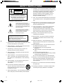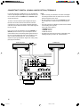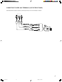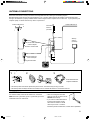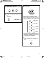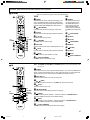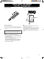
1
U
RX-V595
Natural Sound AV Receiver
OWNER’S MANUAL
RX-V595-cv1
1
3/25/99, 11:54 AM
SAFETY INSTRUCTIONS
8
Ventilation – The unit should be situated so that its location
or position does not interfere with its proper ventilation. For
example, the unit should not be situated on a bed, sofa,
rug, or similar surface, that may block the ventilation
openings; or placed in a built-in installation, such as a
bookcase or cabinet that may impede the flow of air
through the ventilation openings.
9
Heat – The unit should be situated away from heat sources
such as radiators, stoves, or other appliances that produce
heat.
CAUTION
RISK OF ELECTRIC SHOCK
DO NOT OPEN
CAUTION: TO REDUCE THE RISK OF
ELECTRIC SHOCK, DO NOT REMOVE
COVER (OR BACK). NO USER-SERVICEABLE
PARTS INSIDE. REFER SERVICING TO
QUALIFIED SERVICE PERSONNEL.
• Explanation of Graphical Symbols
The lightning flash with arrowhead symbol,
within an equilateral triangle, is intended to alert
you to the presence of uninsulated “dangerous
voltage” within the product’s enclosure that may
be of sufficient magnitude to constitute a risk of
electric shock to persons.
The exclamation point within an equilateral
triangle is intended to alert you to the presence
of important operating and maintenance
(servicing) instructions in the literature
accompanying the appliance.
WARNING
TO REDUCE THE RISK OF FIRE OR
ELECTRIC SHOCK, DO NOT EXPOSE THIS
UNIT TO RAIN OR MOISTURE.
1
Read Instructions – All the safety and operating instructions
should be read before the unit is operated.
2
Retain Instructions – The safety and operating instructions
should be retained for future reference.
3
Heed Warnings – All warnings on the unit and in the
operating instructions should be adhered to.
4
Follow Instructions – All operating and other instructions
should be followed.
5
Water and Moisture – The unit should not be used near
water – for example, near a bathtub, washbowl, kitchen
sink, laundry tub, in a wet basement, or near a swimming
pool, etc.
6
Carts and Stands – The unit should be used only with a
cart or stand that is recommended by the
manufacturer.
6A A unit and cart combination should be moved
with care. Quick stops, excessive force, and
uneven surfaces may cause the unit and cart
combination to overturn.
7
10 Power Sources – The unit should be connected to a power
supply only of the type described in the operating instructions or as marked on the unit.
11 Power-Cord Protection – Power-supply cords should be
routed so that they are not likely to be walked on or
pinched by items placed upon or against them, paying
particular attention to cords at plugs, convenience receptacles, and the point where they exit from the unit.
12 Cleaning – The unit should be cleaned only as recommended by the manufacturer.
13 Nonuse Periods – The power cord of the unit should be
unplugged from the outlet when left unused for a long
period of time.
14 Object and Liquid Entry – Care should be taken so that
objects do not fall into and liquids are not spilled into the
inside of the unit.
15 Damage Requiring Service – The unit should be serviced
by qualified service personnel when:
A. The power-supply cord or the plug has been
damaged; or
B. Objects have fallen, or liquid has been spilled into the
unit; or
C. The unit has been exposed to rain; or
D. The unit does not appear to operate normally or exhibits
a marked change in performance; or
E. The unit has been dropped, or the cabinet damaged.
16 Servicing – The user should not attempt to service the unit
beyond those means described in the operating instructions. All other servicing should be referred to qualified
service personnel.
17 Power Lines – An outdoor antenna should be located away
from power lines.
18 Grounding or Polarization – Precautions should be taken
so that the grounding or polarization is not defeated.
Wall or Ceiling Mounting – The unit should be mounted to a
wall or ceiling only as recommended by the manufacturer.
2
RX-V595-1
2
3/25/99, 11:54 AM
19 For US customers only:
Outdoor Antenna Grounding – If an outside antenna is
connected to this unit, be sure the antenna system is
grounded so as to provide some protection against voltage
surges and built-up static charges. Article 810 of the
National Electrical Code, ANSI/NFPA 70, provides information with regard to proper grounding of the mast and
supporting structure, grounding of the lead-in wire to an
antenna discharge unit, size of grounding conductors,
location of antenna discharge unit, connection to grounding
electrodes, and requirements for the grounding electrode.
Note to CATV system installer:
This reminder is provided to call the CATV system
installer’s attention to Article 820-40 of the NEC that
provides guidelines for proper grounding and, in
particular, specifies that the cable ground shall be
connected to the grounding system of the building, as
close to the point of cable entry as practical.
EXAMPLE OF ANTENNA GROUNDING
MAST
ANTENNA
LEAD IN
WIRE
GROUND
CLAMP
ANTENNA
DISCHARGE UNIT
(NEC SECTION 810–20)
ELECTRIC
SERVICE
EQUIPMENT
GROUNDING CONDUCTORS
(NEC SECTION 810–21)
GROUND CLAMPS
POWER SERVICE GROUNDING
ELECTRODE SYSTEM
(NEC ART 250. PART H)
NEC – NATIONAL ELECTRICAL CODE
FCC INFORMATION (for US customers only)
1. IMPORTANT NOTICE : DO NOT MODIFY THIS UNIT!
This product, when installed as indicated in the
instructions contained in this manual, meets FCC
requirements. Modifications not expressly approved by
Yamaha may void your authority, granted by the FCC,
to use the product.
2. IMPORTANT : When connecting this product to
accessories and/or another product use only high
quality shielded cables. Cable/s supplied with this
product MUST be used. Follow all installation instructions. Failure to follow instructions could void your FCC
authorization to use this product in the USA.
3. NOTE : This product has been tested and found to
comply with the requirements listed in FCC Regulations, Part 15 for Class “B” digital devices. Compliance
with these requirements provides a reasonable level of
assurance that your use of this product in a residential
environment will not result in harmful interference with
other electronic devices.
This equipment generates/uses radio frequencies and,
if not installed and used according to the instructions
found in the users manual, may cause interference
harmful to the operation of other electronic devices.
Compliance with FCC regulations does not guarantee
that interference will not occur in all installations. If this
product is found to be the source of interference, which
can be determined by turning the unit “OFF” and “ON”,
please try to eliminate the problem by using one of the
following measures:
Relocate either this product or the device that is being
affected by the interference.
Utilize power outlets that are on different branch (circuit
breaker or fuse) circuits or install AC line filter/s.
In the case of radio or TV interference, relocate/reorient
the antenna. If the antenna lead-in is 300 ohm ribbon
lead, change the lead-in to coaxial type cable.
If these corrective measures do not produce satisfactory results, please contact the local retailer authorized
to distribute this type of product. If you can not locate
the appropriate retailer, please contact Yamaha
Electronics Corp., U.S.A. 6660 Orangethorpe Ave,
Buena Park, CA 90620.
The above statements apply ONLY to those products
distributed by Yamaha Corporation of America or its
subsidiaries.
We Want You Listening For A Lifetime
YAMAHA and the Electronic Industries Association’s Consumer
Electronics Group want you to get the most out of your equipment by playing it at a safe level. One that lets the sound come
through loud and clear without annoying blaring or distortion –
and, most importantly, without affecting your sensitive hearing.
Since hearing damage from loud sounds is often
undetectable until it is too late, YAMAHA and the
Electronic Industries Association’s Consumer
Electronics Group recommend you to avoid
prolonged exposure from excessive volume levels.
3
RX-V595-1
3
3/25/99, 11:54 AM
SUPPLIED ACCESSORIES
• After unpacking, check that the following parts are included.
• Remote control transmitter
• Indoor FM Antenna
• AM Loop Antenna
• Antenna adapter
(U.S.A. and Canada models only)
• Batteries (size AA, R6, UM-3)
4
RX-V595-1
4
3/25/99, 11:54 AM
FEATURES
● 5 Speaker Configuration
Main:
● Automatic Input Balance Control for
70W + 70W (8Ω) RMS Output
Power, 0.04% THD, 20 Hz – 20 kHz
Center: 70W (8Ω) RMS Output
● Test Tone Generator for Easier Speaker
Balance Adjustment
Power, 0.04% THD, 20 Hz – 20 kHz
Rear:
Dolby Pro Logic Surround
70W + 70W (8Ω) RMS Output
Power, 0.04% THD, 20 Hz – 20 kHz
● Speaker Output Mode Changing
Capability
● 40-Station Random Access Preset Tuning
● Digital Sound Field Processor
● Automatic Preset Tuning
● Dolby Digital Decoder
● Dolby Pro Logic Surround Decoder
● Preset Station Shifting Capability
(Preset Editing)
● CINEMA DSP: Theater-like Sound
Experience by the Combination of Dolby
Surround and YAMAHA DSP Technology
● 6-Channel External Decoder Input for DTS
● Video Signal Input/Output Capability
● SLEEP Timer
● Universal Remote Control
Transmitter with Preset Manufacturer
and other future formats
Codes
CONTENTS
SUPPLIED ACCESSORIES ........................................... 4
FEATURES .................................................................... 5
CAUTION ....................................................................... 6
● Information about DSP
● Introduction
● Advanced Information
FEATURES ON SOUND EFFECT ................................. 7
CONTROLS AND THEIR FUNCTIONS ......................... 9
ADJUSTMENTS
IN THE “SET MENU” MODE ................................... 43
● Preparation
● Remote Control Transmitter
SPEAKER SETUP ....................................................... 12
CONNECTIONS ........................................................... 14
ADJUSTMENTS
BEFORE USING THIS UNIT .................................. 22
REMOTE CONTROL TRANSMITTER ......................... 45
SETUP CODES ........................................................... 50
NOTES ABOUT THE REMOTE CONTROL
TRANSMITTER ...................................................... 51
USING DIGITAL SOUND FIELD
PROCESSOR (DSP) .............................................. 37
● Basic Oparation
BASIC OPERATIONS .................................................. 27
TUNING OPERATIONS ............................................... 31
SETTING THE SLEEP TIMER ..................................... 36
TROUBLESHOOTING ................................................. 52
SPECIFICATIONS ....................................................... 54
LIST OF MANUFACTURER’S CODES ........................ 56
5
RX-V595-1 p5
5
8/21/98, 7:31 PM
CAUTION : READ THIS BEFORE OPERATING YOUR UNIT.
1.
To assure the finest performance, please read this manual
carefully. Keep it in a safe place for future reference.
2.
Install this unit in a cool, dry, clean place – away from
windows, heat sources, sources of excessive vibration,
dust, moisture and cold. Avoid sources of humming
(transformers, motors). To prevent fire or electrical shock,
do not expose the unit to rain or water.
3.
Never open the cabinet. If something drops into the set,
contact your dealer.
4.
Do not use force on switches, controls or connection wires.
When moving the unit, first disconnect the power plug and
the wires connected to other equipment. Never pull the
wires themselves.
5.
The openings on the unit cover assure proper ventilation of
the unit. If these openings are obstructed, the temperature
inside the unit will rise rapidly. Therefore, avoid placing
objects against these openings, and install the unit in a
well-ventilated area to prevent fire and damage.
<Singapore model only>
Be sure to allow a space of at least 20 cm behind, 20 cm
on the both sides and 30 cm above the top panel of the unit
to prevent fire and damage.
6.
The voltage used must be the same as that specified on
this unit. Using this unit with a higher voltage than specified is dangerous and may result in fire or other accidents.
YAMAHA will not be held responsible for any damage
resulting from use of this unit with a voltage other than
specified.
7.
Digital signals generated by this unit may interfere with
other equipment such as tuners, receivers or TVs. Move
this unit farther away from such equipment if interference is
observed.
8.
Always set the VOLUME control to “∞” before starting the
audio source play. Increase the volume gradually to an
appropriate level after playback has been started.
9.
Do not attempt to clean the unit with chemical solvents; this
might damage the finish. Use a clean, dry cloth.
This unit is not disconnected from the AC power source as
long as it is connected to the wall outlet, even if this unit
itself is turned off. This state is called the standby mode.
In this state, this unit is designed to consume a very small
quantity of power.
FREQUENCY STEP switch
(China and General Models only)
Because the interstation frequency spacing differs in
different areas, set the FREQUENCY STEP switch (located
at the rear) according to the frequency spacing in your area.
Before setting this switch, disconnect the AC power plug of
this unit from the AC outlet.
FOR CANADIAN CUSTOMERS
TO PREVENT ELECTRIC SHOCK, MATCH WIDE BLADE
OF PLUG TO WIDE SLOT AND FULLY INSERT.
THIS CLASS B DIGITAL APPARATUS COMPLIES WITH
CANADIAN ICES-003.
WARNING
Do not change the IMPEDANCE SELECTOR switch setting
while the power of this unit is on, otherwise this unit may be
damaged.
IF THIS UNIT FAILS TO TURN ON WHEN THE STANDBY/
ON SWITCH IS PRESSED, the IMPEDANCE SELECTOR
switch may not be fully set to either end. If so, set the switch
to either end fully.
IMPEDANCE SELECTOR
(U.S.A. model)
IMPEDANCE SELECTOR
SET BEFORE POWER ON
MAIN
A OR B: 4ΩMIN. /SPEAKER
A + B: 8ΩMIN. /SPEAKER
CENTER: 6ΩMIN. /SPEAKER
REAR : 6ΩMIN. /SPEAKER
10. Be sure to read the “TROUBLESHOOTING” section
regarding common operating errors before concluding that
the unit is faulty.
MAIN
A OR B: 8ΩMIN. /SPEAKER
A + B:I6ΩMIN. /SPEAKER
CENTER: 8ΩMIN. /SPEAKER
REAR : 8ΩMIN. /SPEAKER
11. When not planning to use this unit for long periods of time
(ie., vacation, etc.), disconnect the AC power plug from the
wall outlet.
12. To prevent lightning damage, disconnect the AC power
plug and disconnect the antenna cable when there is an
electrical storm.
13. Grounding or polarization – Precautions should be taken so
that the grounding or polarization of an appliance is not
defeated.
14. AC outlet
Do not connect audio equipment to the AC outlet on the
rear panel if that equipment requires more power than the
outlet is rated to provide.
15. Voltage Selector (China and General Models only)
The voltage selector on the rear panel of this unit must be
set for your local main voltage BEFORE plugging into the
AC main supply.
Voltages are 110/120/220/240 V AC, 50/60 Hz.
AC OUTLETS
SWITCHED
100W MAX. TOTAL
IMPORTANT
Please record the serial number of this unit in the space
below.
Serial No.:
The serial number is located on the rear of the unit.
Retain this Owner’s Manual in a safe place for future
reference.
WARNING
TO REDUCE THE RISK OF FIRE OR ELECTRIC SHOCK,
DO NOT EXPOSE THIS UNIT TO RAIN OR MOISTURE.
6
RX-V595-1
6
MAINS
3/25/99, 11:54 AM
FEATURES ON SOUND EFFECT
This unit incorporates a sophisticated, multi-program digital
sound field processor. The processor allows you to electronically expand and change the shape of the audio sound field
from both audio and video sources, creating a theater-like
experience in your listening room. This unit has a total of 8
digital sound field processor (DSP) modes. You can create an
excellent audio sound field by selecting a suitable sound field
(this will, of course, depend on what you will be listening to),
and adding desired adjustments.
In addition, this unit incorporates a Dolby Pro Logic Surround
decoder and Dolby Digital decoder for multi-channel sound
reproduction of Dolby Surround encoded video sources. The
operation of the Dolby Pro Logic Surround or Dolby Digital
decoder can be controlled by selecting a corresponding DSP
program including combined operations of the YAMAHA DSP
and the Dolby Pro Logic Surround or Dolby Digital decoder.
Digital Sound Field Processing
What is it that makes live music so good? Today’s advanced
sound reproduction technology lets you get extremely close to
the sound of a live performance, but chances are you’ll still
notice something missing, the acoustic environment of the live
concert hall. Extensive research into the exact nature of the
sonic reflections that create the ambience of a large hall has
made it possible for YAMAHA engineers to bring you this same
sound in your listening room, so you’ll feel all the sound of a
live concert.
Furthermore, our technicians, armed with sophisticated
measuring equipment, have even made it possible to capture
the acoustics of a variety of actual concert halls, theaters, etc.
from around the world, to allow you to accurately re-create any
one of these live performance environments, all in your home.
Dolby Pro Logic Surround
This unit employs a Dolby Pro Logic Surround decoder similar
to professional Dolby Stereo decoders used in many movie
theaters. By using the Dolby Pro Logic Surround decoder, you
can experience the dramatic realism and impact of Dolby
Surround movie theater sound in your own home. Dolby Pro
Logic employs a four channel five speaker system. The Pro
Logic Surround system divides the input signal into four levels:
the left and right main channels, the center channel (used for
dialog), and the rear surround sound channels (used for sound
effects, background noise, and other ambient noises). The
center channel allows listeners seated in even less-than-ideal
positions to hear the dialog originating from the action on the
screen while experiencing good stereo imaging.
Dolby Surround is encoded on the sound track of pre-recorded
video tapes, laser discs, and some TV/cable broadcasts. When
you play a source encoded with Dolby Surround on this unit,
the Dolby Pro Logic Surround decoder decodes the signal and
distributes the surround-sound effects.
This Dolby Pro Logic Surround decoder employs a digital signal
processing system. This system improves the stability of sound
at each channel and crosstalk between channels, so that
positioning of sounds around the room is more accurate
compared with conventional analog signal processing systems.
In addition, this unit features a built-in automatic input balance
control. This always assures you the best performance without
manual adjustment.
Dolby Digital
The built-in Dolby Digital decoder leads you into a totally new
sound experiences.
Dolby Digital is a new generation of multi-channel digital audio
technology, or the newest spatial sound processing format
developed for 35 mm film-movies by employing a new kind of
low bit-rate audio coding.
Dolby Digital is a digital surround sound system that provides
completely independent multi-channel audio to consumers. In
multi-channel form, Dolby Digital provides five full range
channels in what is sometimes referred to as a “3/2” configuration: three front channels (left, center and right), plus two
surround channels. A sixth bass-only effect channel is also
provided for output of LFE (low frequency effect), or low bass
effects that are independent of other channels. This channel is
counted as 0.1, thus giving rise to the term 5.1 channels in
total.
Compared to Dolby Pro Logic that is referred to a “3/1” system
(left front, center, right front and just one surround channel),
Dolby Digital features two surround channels, called stereo or
split surrounds, each offering the same full range fidelity as the
three front channels.
Sound of wide dynamic range reproduced by the five full range
channels presents listeners much excitement that has never
been experienced before. Precise sound orientation by the
discrete digital sound processing expands realism that the
original movie possesses.
LD and DVD are home audio formats that could benefit from
Dolby Digital. In the near future, Dolby Digital will also be
applied to DBS, CATV and HDTV. The ongoing release of
Dolby Stereo Digital theatrical films now underway will provide
an immediate source of Dolby Digital encoded video software.
7
RX-V595-1
7
3/25/99, 11:54 AM
Manufactured under license from Dolby Laboratories Licensing
Corporation. “Dolby”, “Pro Logic”, and the double-D symbol are
trademarks of Dolby Laboratories Licensing Corporation.
Copyright 1992 Dolby Laboratories, Inc. All rights reserved.
• Dynamic range (sound scale) of source can be changed
so that it will be suitable for the listening conditions.
• Output of low bass from any channel can be assigned to
either the MAIN SPEAKERS terminals or SUBWOOFER
terminal to maximize system performance.
• Output of LFE can be assigned to either the MAIN
SPEAKERS terminals or SUBWOOFER terminal to
maximize system performance.
The following original functions make the surround-sound effect
of Dolby Digital become the most suitable for your audio
system and the listening conditions.
Dolby Surround + DSP (CINEMA DSP)
Dolby Surround sound system shows its full ability in a large
movie theater, because movie sounds are originally designed to
be reproduced in a large movie theater using many speakers.
It is difficult to create a sound environment similar to that of a
movie theater in your listening room, because the room size,
materials of inside walls, the number of speakers, etc. of your
listening room is much different from those of a movie theater.
YAMAHA DSP technology made it possible to present you with
nearly the same sound experience as that of a large movie
theater in your listening room by compensating for lack of
presence and dynamics in your listening room with its original
digital sound fields combined with Dolby Surround sound field.
CINEMA DSP
The YAMAHA “CINEMA DSP” logo indicates those programs
are created by the combination of Dolby Surround and
YAMAHA DSP technology.
Dolby Pro Logic + 2 Digital Sound Fields
Dolby Digital + 3 Digital Sound Fields
Digital sound fields are created on the presence side and the
rear surround side of the Dolby Pro Logic Surround-decoded
sound field respectively. They create a wide acoustic
environment and emphasize surround-effect in the room,
letting you feel much presence as if you are watching a
movie in a popular Dolby Stereo theater.
Digital sound fields are created on the presence side and the
independent left and right surround sides of the Dolby Digitaldecoded sound field respectively. They create a wide
acoustic environment and much surround effect in the room
without losing high channel separation. With wide dynamic
range of Dolby Digital sound, this sound field combination lets
you feel as if you are watching a movie in the newest Dolby
Stereo Digital theater. This will be the most ideal home
theater sound at the present time.
This combination is available when the sound field program
DOLBY PRO LOGIC ENHANCED/DOLBY DIGITAL
ENHANCED, 70 mm MOVIE THEATER/DIGITAL MOVIE
THEATER or TV SPORTS is selected, and the input signal of
source is analog, PCM audio or encoded with the Dolby
Digital in 2-channel.
This combination is available when the sound field program
DOLBY PRO LOGIC ENHANCED/DOLBY DIGITAL
ENHANCED, 70 mm MOVIE THEATER/DIGITAL MOVIE
THEATER or TV SPORTS is selected, and the input signal of
source is encoded with the Dolby Digital (except in 2-channel).
8
RX-V595-1
8
3/25/99, 11:54 AM
CONTROLS AND THEIR FUNCTIONS
FRONT PANEL
1 STANDBY/ON
6 TUNING MODE (AUTO/MAN’L MONO)
Press this switch to turn the power of this unit on. Press it
again to turn this unit into the standby mode.
Press this button to switch the tuning mode to automatic or
manual. To select the automatic tuning mode, press this button
so that the “AUTO TUNING” indicator lights up on the display.
To select the manual tuning mode, press this button so that the
“AUTO TUNING” indicator goes off.
Standby mode
In this state, this unit consumes a very small quantity of
power to receive infrared-signals from the remote control
transmitter.
2 Remote control sensor
Receives signals from the remote control transmitter.
3 Display
7 FM/AM
Press this button to switch the reception band to FM or AM.
8 TUNING UP/DOWN
This button is used for tuning. Press the UP side to tune in to
higher frequencies, and press the DOWN side to tune in to
lower frequencies.
Shows various information. (For details, refer to page 11.)
9 TAPE/MD MON / EXT. DECODER
4 MEMORY (MAN’L/AUTO FM)
Press this button to play a tape or an MD. The “TAPE/MD
MON” indicator lights up on the display.
When you press the button next, the “TAPE/MD MON” indicator
goes off and “EXT. DECDR” appears on the display and you
can play the signal connected to the EXTERNAL DECODER
INPUT terminals.
Press this button to store the broadcasting stations.
When this button is pressed and held for more than three
seconds, the automatic preset tuning begins.
5 EDIT
This button is used to exchange the places of two preset
stations with each other.
0 INPUT
Turn this selector to select the program source (VCR, VIDEO
AUX, TV/DBS, DVD/LD, CD, TUNER, PHONO) to listen to or
watch.
The name of the selected program source appears on the
display.
9
RX-V595-1
9
3/25/99, 11:54 AM
q INPUT MODE
i BALANCE
Switches the DVD/LD and TV/DBS input signal mode (AUTO/
ANALOG).
This control is used to raise or lower the volume level.
This control is effective only for the sound from the main
speakers.
Adjusts the balance of the output volume to the left and right
speakers to compensate for sound imbalance caused by
speaker location or listening room conditions.
e PHONES jack
o TIME/LEVEL
When you use headphones, connect the headphones to the
PHONES jack. You can listen to the sound to be output from
the main speakers through headphones.
When using headphones only, set both SPEAKERS A and B to
the OFF position and switch off the digital sound field processor
(so that no DSP program name appears on the display) by
pressing EFFECT.
Press this button to select the setting of delay time or speaker
output levels in the TIME/LEVEL mode.
w VOLUME
p +/–
These buttons are used to adjust settings of the SET MENU
mode and the TIME/LEVEL mode. In the TIME LEVEL mode,
press + to increase delay time or speaker output levels. Press
– to decrease delay time or speaker output levels.
PHONES
a SET MENU
Press this button to select functions in the SET MENU mode.
s PROGRAM selector
Press or to select the DSP program.
The name of the selected program appears on the display.
d EFFECT
Set A or B (or both A and B) to the ON position for the main
speaker system (connected to this unit) you will use. Set it (or
them) for the main speaker system you will not use to the OFF
position.
Switches on and off the output from the center and rear
speakers so that the sound becomes normal 2-channel.
* Even if the output from the center and rear speakers is off,
when the Dolby Digital is decoded, the signals at all channels
are distributed to the main channels and output from the main
speakers.
t A/B/C/D/E
f VIDEO AUX terminals
Press this button to select a group (A to E) of preset stations.
Connect an auxiliary video or audio input source unit such as a
camcorder to these terminals. The source connected to these
terminals can be selected by INPUT.
r SPEAKERS
y Preset station number selector
Select a preset station number (1 to 8).
u Tone controls
These controls are effective only for the sound from the main
speakers.
BASS
Used to increase or decrease the low frequency response. The
“0” position produces flat response.
TREBLE
Used to increase or decrease the high frequency response.
The “0” position produces flat response.
10
RX-V595-1
10
3/25/99, 11:54 AM
DISPLAY PANEL
1 Multi-information display
6 Signal-level meter
Displays various information, for example station frequency,
preset station number and name of selected input source.
Indicates the signal level of the received station.
If multipath interference is detected, the indication decreases.
2 MEMORY indicator
7
When MEMORY is pressed, this indicator flashes for about five
seconds. During this period, the displayed station can be
stored to the memory.
3 AUTO TUNING indicator
Lights up when this unit is in the automatic tuning mode.
4 TAPE/MD MON indicator
Lights up when the tape deck (or MD recorder etc.) is selected as
the input source by pressing TAPE/MD MON / EXT. DECODER
on the front panel or TAPE/MD on the remote control transmitter.
,
and
indicators
“
” lights up when the built-in Dolby Digital decoder is
on and the signals of selected source encoded with the Dolby
Digital is not in 2-channel. “
” lights up when the built-in
digital sound field processor is on, and “
” lights up
when the built-in Dolby Pro Logic Surround decoder is on.
Depending on the selected DSP program, both “
” and
“
”, or both “
” and “
” will light up.
8 SLEEP indicator
Lights up while the built-in SLEEP timer is functioning.
5 STEREO indicator
Lights up when an FM stereo broadcast with sufficient signal
strength is received.
11
RX-V595-1
11
3/25/99, 11:54 AM
SPEAKER SETUP
SPEAKERS TO BE USED
This unit is designed to provide the best sound-field quality with
a 5-speaker configuration, using main speakers, rear speakers
and a center speaker.
The main speakers are used for the main source sound plus
the effect sounds. They will probably be the speakers from
your present stereo system. The rear speakers are used for
the effect and surround sounds, and the center speaker is for
the center sounds (dialog, vocals, etc.). If for some reason it is
not practical to use a center speaker, you can do without it.
Best results, however, are obtained with the full system.
Use of a subwoofer expands your sound field
It is also possible to further expand your system with the
addition of a subwoofer and amplifier. The use of a subwoofer
is effective not only for reinforcing bass frequencies from any or
all channels, but also for reproducing the LFE (low frequency
effect) sound with high fidelity when playing back a source with
the Dolby Digital decoded. You may wish to choose the
convenience of a YAMAHA Active Servo Processing Subwoofer
System, which has its own built-in power amplifier.
The main speakers should be high performance models and
have enough power handling capacity to accept the maximum
output of your audio system.
Other speakers do not have to be equal to the main speakers.
For precise sound localization, however, it is ideal to use high
performance models that can reproduce sounds in the full
range for the center speaker and the rear speakers.
SPEAKER CONFIGURATION
5-Speaker Configuration
4-Speaker Configuration
This configuration is the most effective and recommended one.
When playing back a source using the DSP program,
DOLBY PRO LOGIC/DOLBY DIGITAL, DOLBY PRO LOGIC
ENHANCED/DOLBY DIGITAL ENHANCED, 70 mm MOVIE
THEATER/DIGITAL MOVIE THEATER, MONO MOVIE or TV
SPORTS, or when playing back a source which contains
center-channel signals (dialog, vocals, etc.) using any DSP
program with the Dolby Digital decoded, conversations will be
output from the center speaker and the ambience will be
excellent.
Note: Set the CNTR (CENTER SPEAKER) mode to the
“LARGE” or “SMALL” position. (For details, see
page 22.)
The center speaker is not used in this configuration. When
playing back a source using the DSP program, DOLBY PRO
LOGIC/DOLBY DIGITAL, DOLBY PRO LOGIC ENHANCED/
DOLBY DIGITAL ENHANCED, 70 mm MOVIE THEATER/
DIGITAL MOVIE THEATER, MONO MOVIE or TV SPORTS, or
when playing back a source which contains center-channel
signals (dialog, vocals, etc.) using any DSP program with the
Dolby Digital decoded, the center sound is output from the left
and the right main speakers. However, the sound effect of
other programs will be the same as that of the 5-speaker
configuration.
Note: Be sure to set the CNTR (CENTER SPEAKER) mode to
the “NONE” position. (For details, see page 22.)
Main L
Center
Main R
Main L
Dialog
Dialog
Surround sound
Rear R
Rear L
Surround sound
Rear L
12
RX-V595-2
12
Main R
3/25/99, 11:54 AM
Rear R
SPEAKER PLACEMENT
When you place the speakers, refer to the following diagram:
Main:
The position of your present stereo speaker
system.
Rear:
Behind your listening position, facing slightly
inward. Nearly 1.8 m (approx. 6 feet) up from the
floor.
Center:
Precisely between the main speakers. (To avoid
interference with TV sets, use a magnetically
shielded speaker.)
Subwoofer: The position of the subwoofer is not so critical
because low bass tones are not highly directional.
Main speaker
Center speaker
Rear speaker
Subwoofer
13
RX-V595-2
13
3/25/99, 11:54 AM
CONNECTIONS
Never plug in this unit and other components until all connections are completed.
CONNECTIONS WITH OTHER COMPONENTS
When making connections between this unit and other components, be sure all connections are made correctly, that is to say L
(left) to L, R (right) to R, “+” to “+” and “–” to “–”. Also, refer to the owner’s manual for each component to be connected to this unit.
* If you have YAMAHA components numbered as !, #, $, etc. on the rear panel, connections can be made easily by making sure
to connect the output (or input) terminals of each component to the same-numbered terminals of this unit.
Turntable
Monitor TV
DVD player, LD player, etc.
(U.S.A. model)
MAIN
CENTER
SURROUND
FM
ANT
MAIN
A OR B: 4ΩMIN. /SPEAKER
A + B: 8ΩMIN. /SPEAKER
CENTER: 6ΩMIN. /SPEAKER
REAR : 6ΩMIN. /SPEAKER
OPTICAL
DVD/LD
L
SET BEFORE POWER ON
L
COAXIAL
75Ω UNBAL.
IMPEDANCE SELECTOR
DIGITAL SIGNAL
EXTERNAL DECODER INPUT
DVD/LD
TV/DBS
R
MAIN
A OR B: 8ΩMIN. /SPEAKER
A + B:I6ΩMIN. /SPEAKER
CENTER: 8ΩMIN. /SPEAKER
REAR : 8ΩMIN. /SPEAKER
SUB WOOFER
GND
VIDEO SIGNAL
GND
MAINS
AC OUTLETS
AM
ANT
R
MONITOR
OUT
IN
DVD/LD
TV/DBS
PHONO
L
R
R
IN
OUT
(PLAY)
(REC)
TAPE/MD
CD
L
OUT
OUTPUT
IN
DVD/LD
SWITCHED
100W MAX. TOTAL
VCR
AUDIO SIGNAL
L
REAR
(SORROUND)
TV/DBS
OUT
VCR
SUB
WOOFER
UAL FOR CORRECT SETTING.
To AC outlet
CD player
,
Tape deck,
MD recorder, etc.
TV/DBS tuner
VCR
(Video cassette recorder)
: See the next page.
14
RX-V595-2
14
3/25/99, 11:54 AM
SWITCHED AC OUTLET(S)
GND terminal (For turntable use)
(U.S.A., Canada, Singapore, China and General models)
........................................................... 2 SWITCHED OUTLETS
Connecting the ground wire of the turntable to the GND
terminal will normally minimize hum, but in some cases better
results may be obtained with the ground wire disconnected.
(Australia model) ................................... 1 SWITCHED OUTLET
Use these to connect the power cords from your components to
this unit.
The power to the SWITCHED outlets is controlled by this unit’s
STANDBY/ON or the provided remote control transmitter’s
POWER and STANDBY. These outlets will supply power to
any component whenever this unit is turned on.
The maximum power (total power consumption of components)
that can be connected to the SWITCHED AC OUTLET(S) is
100 watts.
CONNECTING TO AN EXTERNAL DECODER
When using the DTS or other decoder with 6-channel discrete outputs, connect the 6CH DISCRETE OUTPUT terminals of the
decoder to the EXTERNAL DECODER INPUT terminals of this unit.
DTS or other decoder with 6-channel
discrete outputs
6CH DISCRETE OUTPUT
MAIN
CENTER
SURROUND
L
L
R
R
SUB
WOOFER
(U.S.A. model)
DIGITAL SIGNAL
EXTERNAL DECODER INPUT
MAIN
CENTER
SURROUND
COAXIAL
75Ω UNBAL.
FM
ANT
OPTICAL
DVD/LD
L
DVD/LD
TV/DBS
R
SUB WOOFER
GND
VIDEO SIGNAL
GND
AM
ANT
MONITOR
OUT
IN
DVD/LD
TV/DBS
OUT
VCR
AUDIO SIGNAL
PHONO
CD
L
L
R
R
IN
OUT
(PLAY)
(REC)
TAPE/MD
OUTPUT
IN
DVD/LD
TV/DBS
OUT
VCR
SUB
WOOFER
DVD player, LD player or other
unit with digital outputs
15
RX-V595-2
15
3/25/99, 11:54 AM
CONNECTING TO DIGITAL (COAXIAL AND/OR OPTICAL) TERMINALS
Notes
• When connecting an audio/video unit to both of the digital
and analog terminals of this unit, make sure to connect to
both terminals of the same name.
• Be sure to attach the covers when the OPTICAL terminals
are not being used, in order to protect the terminals from
dust.
• The input signal from the DVD/LD input terminals is selected
in the following order of priority.
(input mode: AUTO position)
1 COAXIAL terminal
2 OPTICAL terminal
3 ANALOG terminal
• All digital audio signal input terminals are applicable to the
sampling frequency of 32 kHz, 44.1 kHz and 48 kHz.
If your DVD (LD) player, TV/DBS tuner, etc. are equipped with
coaxial or optical digital audio signal output terminals, they can
be connected to this unit’s COAXIAL and/or OPTICAL digital
signal input terminals.
To make a connection between optical digital audio signal
terminals, remove the cover from each terminal, and then
connect them by using a commercially available optical fiber
cable that conforms to EIAJ standards. Other cables might not
function correctly.
Even if you connect an audio/video unit to the COAXIAL (or
OPTICAL) terminal of this unit, you must keep the unit connected with the same named analog audio signal terminals of
this unit, because digital signal cannot be recorded by a tape
deck or VCR connected to this unit. You can switch the
selection of input signals between “digital” and “analog” easily.
(See page 29 for details.)
DVD or LD player
TV/DBS tuner
(U.S.A. model)
DIGITAL SIGNAL
EXTERNAL DECODER INPUT
MAIN
CENTER
SURROUND
COAXIAL
75Ω UNBAL.
FM
ANT
OPTICAL
DVD/LD
L
DVD/LD
TV/DBS
R
SUB WOOFER
GND
VIDEO SIGNAL
GND
AM
ANT
MONITOR
OUT
IN
DVD/LD
TV/DBS
OUT
VCR
AUDIO SIGNAL
PHONO
CD
L
L
R
R
IN
OUT
(PLAY)
(REC)
TAPE/MD
OUTPUT
IN
DVD/LD
TV/DBS
OUT
VCR
SUB
WOOFER
16
RX-V595-2
16
3/25/99, 11:54 AM
CONNECTING TO VIDEO AUX TERMINALS (ON THE FRONT PANEL)
These terminals are used to connect any video input source, such as a camcorder, to this unit.
VIDEO AUX
VIDEO
L AUDIO R
R
L
VIDEO
Camcorder
17
RX-V595-2
17
3/25/99, 11:54 AM
CONNECTING SPEAKERS
Main speakers A
Right
Main speakers B
Left
Right
Left
SPEAKERS
R
MAIN
CENTER R
L
REAR
(SORROUND)
L
Rear speakers
OUTPUT
Left
Right
CAUTION SEE INSTRUCTION MANUAL FOR CORRECT SETTING.
SUB
WOOFER
Center speaker
Subwoofer system
Note
Use speakers with the specified impedance shown on the
rear panel of this unit.
Note on main speaker connections:
One or two speaker systems can be connected to this unit. If
you use only one speaker system, connect it to either the
SPEAKERS A or B terminals.
Note on a subwoofer connection:
You may wish to add a subwoofer to reinforce low frequencies
or to output low bass sound from the subwoofer channel.
If you have a subwoofer with built-in amplifier, including the
YAMAHA Active Servo Processing Subwoofer System, connect
the SUBWOOFER OUTPUT terminal of this unit to the input
terminal of the subwoofer system.
If you have an amplifier and a subwoofer, connect the
SUBWOOFER OUTPUT terminal of this unit to the input
terminal of the subwoofer amplifier, and then connect the
speaker terminals of the subwoofer amplifier to the subwoofer.
When the input signals to this unit are in normal 2-channel
stereo, this terminal outputs only frequencies below 90 Hz from
the main and center channels. When discrete signals are input
to this unit and are selected as the input source, this terminal
outputs signals from the subwoofer channel.
Note on center speaker connection:
Center speaker can be connected to this unit. Place it on or
under the TV.
18
RX-V595-2
18
3/25/99, 11:54 AM
How to connect
Connect the SPEAKERS terminals to your speakers with wire of the proper gauge, cut as short as possible. If the connections are
faulty, no sound will be heard from the speakers. Make sure that the polarity of the speaker wires is correct, that is the + and –
markings are observed. If these wires are reversed, the sound will be unnatural and lack bass.
Caution
Do not let the bare speaker wires touch each other and do not let them touch any metal part of this unit. This could
damage this unit and/or speakers.
For connecting to the MAIN SPEAKERS
terminals
For connecting to the REAR and CENTER
SPEAKERS terminals
Red: positive (+)
Black: negative (–)
Red: positive (+)
Black: negative (–)
1 Unscrew the knob.
2 Insert the bare wire.
[Remove approx. 5 mm
(1/4”) insulation from the
speaker wires.]
3 Tighten the knob and
secure the wire.
1 Press the tab.
2 Insert the bare wire.
[Remove approx. 5 mm
(1/4”) insulation from
the speaker wires.]
3 Release the tab and
secure the wire.
Banana plug connections are also possible (except for
Singapore model). Simply insert the banana plug connector
into the corresponding terminal.
19
RX-V595-2
19
3/25/99, 11:54 AM
IMPEDANCE SELECTOR SWITCH
WARNING
Do not change the IMPEDANCE SELECTOR switch setting
while the power of this unit is on, otherwise this unit may be
damaged.
IF THIS UNIT FAILS TO TURN ON WHEN THE STANDBY/
ON SWITCH IS PRESSED, the IMPEDANCE SELECTOR
switch may not be fully set to either end. If so, set the switch
to either end fully.
Select the position whose requirements your speaker system
meets.
(Upper position)
Main:
If you use one pair of main speakers, the impedance of
each speaker must be 4 Ω or higher.
If you use two pairs of main speakers, the impedance
of each speaker must be 8 Ω or higher.
Center: The impedance of the speaker must be 6 Ω or higher.
IMPEDANCE SELECTOR
(U.S.A. model)
Rear:
The impedance of each speaker must be 6 Ω or
higher.
IMPEDANCE SELECTOR
SET BEFORE POWER ON
(Lower position)
MAIN
A OR B: 4ΩMIN. /SPEAKER
A + B: 8ΩMIN. /SPEAKER
CENTER: 6ΩMIN. /SPEAKER
REAR : 6ΩMIN. /SPEAKER
Main:
MAIN
A OR B: 8ΩMIN. /SPEAKER
A + B:I6ΩMIN. /SPEAKER
CENTER: 8ΩMIN. /SPEAKER
REAR : 8ΩMIN. /SPEAKER
MAINS
AC OUTLETS
SWITCHED
100W MAX. TOTAL
L
If you use one pair of main speakers, the impedance of
each speaker must be 8 Ω or higher.
If you use two pairs of main speakers, the impedance
of each speaker must be 16 Ω or higher.
Center: The impedance of the speaker must be 8 Ω or higher.
Rear:
The impedance of each speaker must be 8 Ω or
higher.
20
RX-V595-2
20
3/25/99, 11:55 AM
ANTENNA CONNECTIONS
Each antenna should be correctly connected to the designated terminals, referring to the following diagram.
Both AM and FM indoor antennas are included with this unit. In general, these antennas will probably provide sufficient signal
strength. Nevertheless, a properly installed outdoor antenna will give clearer reception than an indoor one. If you experience poor
reception quality, an outdoor antenna may result in improvement.
Outdoor FM antenna
Outdoor AM antenna
Indoof FM
antenna
(included)
(U.S.A. model)
75-ohm/300-ohm
antenna adapter
AM loop
antenna
(included)
75Ω UNBAL.
FM
ANT
75-ohm coaxial cable
GND
GND
AM
ANT
75-ohm/300-ohm
antenna adapter
PHONO
300-ohm feeder
Ground
Connecting the AM loop antenna
1
2
1
3
2
Orient so that the best
reception is obtained.
3
* The AM loop antenna should be placed away from this unit. The antenna may be hung on a wall.
* The AM loop antenna always should be connected, even if an outdoor AM antenna is connected to this unit.
GND TERMINAL
For maximum safety and minimum interference, connect the
GND terminal to a good earth ground. A good earth ground is a
metal stake driven into moist earth.
Notes
• When connecting the indoor FM
antenna, insert its connector into the
FM ANT terminal firmly.
• If you need an outdoor FM antenna
to improve FM reception quality,
either 300-ohm feeder or coaxial
cable may be used. In locations
troubled by electrical interference, coaxial cable is preferable.
21
RX-V595-2
21
3/25/99, 11:55 AM
ADJUSTMENTS BEFORE USING THIS UNIT
SELECTING THE OUTPUT MODES
This unit provides you the following five functions to determine the method of distributing output signals to speakers suitable for
your audio system. When speaker connections are all completed, select a proper position on each function to make the best use of
your speaker system. (See “ADJUSTMENTS IN THE ‘SET MENU’ MODE” on page 43.)
1. CNTR (CENTER SPEAKER)
4. BASS (LFE/BASS OUT)
2. REAR (REAR SPEAKER)
5. M.LVL (MAIN LEVEL)
3. MAIN (MAIN SPEAKER)
DESCRIPTION OF EACH FUNCTION
1. CNTR (CENTER SPEAKER)
Choices: LARGE/SMALL/NONE
Preset position: LARGE
LARGE: Select this position when your center speaker is
approximately the same size as the main speakers.
SMALL: Select this position when you use a center speaker
that is smaller than the main speakers.
In this position, low bass signals (below 90 Hz) at the
center channel are output from the main speakers (or
the SUBWOOFER OUTPUT terminal if the SMALL
position is selected on “3. MAIN” and the SW position
is selected on “4. BASS”).
NONE: Select this position when you do not have a center
speaker. The center channel sound will be output
from the left and right main speakers.
2. REAR (REAR SPEAKER)
Choices: LARGE/SMALL
Preset position: LARGE
LARGE: Select this position if your rear speakers have a high
ability for bass reproduction, or a subwoofer is
connected to the rear speaker in parallel.
In this position, full range signals are output from the
rear speakers.
SMALL: Select this position if your rear speakers do not have
a high ability for bass reproduction.
In this position, low bass signals (below 90 Hz) at the
rear channels are output from the SUBWOOFER
OUTPUT terminal (or the main speakers if the MAIN
position is selected on “4. BASS”).
3. MAIN (MAIN SPEAKER)
Choices: LARGE/SMALL
Preset position: LARGE
LARGE: Select this position if your main speakers have a
high ability for bass reproduction.
In this position, full range signals present at the main
channels are output from the main speakers.
SMALL: Select this position if your main speakers do not
have a high ability for bass reproduction. However, if
your system does not include a subwoofer, do not
select this position.
In this position, low bass signals (below 90 Hz) at the
main channels are output from the SUBWOOFER
OUTPUT terminal if the SW or BOTH position is
selected on “4. BASS”.
4. BASS (LFE/BASS OUT)
Choices: SW/MAIN/BOTH
Preset position: SW
MAIN:
Select this position if your system does not include a
subwoofer.
In this position, full range signals present at the main
channels, signals from the LFE channel and other
low bass signals that are selected on “1. CNTR” to
“3. MAIN” to be distributed from other channels are
output from the main speakers.
SW/BOTH:
Select either the SW or BOTH position if your
system includes a subwoofer.
In either position, signals at LFE channel and other
low bass signals that are selected on “1. CNTR” to
“3. MAIN” to be distributed from other channels are
output from the SUBWOOFER OUTPUT terminal.
When the LARGE position is selected on “3. MAIN”,
in the SW position, no signal is distributed from the
main channels to the SUBWOOFER OUTPUT
terminal, however in the BOTH position, low bass
signals from the main channels are output to both of
the main speakers and the SUBWOOFER OUTPUT
terminal.
5. M.LVL (MAIN LEVEL)
Choices: NORMAL (NRML)/–10 dB
Preset position: NORMAL (NRML)
NORMAL (NRML):
Normally select this position.
–10 dB: Select this position if the sound output from the main
speakers is too loud and cannot be balanced with
the sound output from the center and rear speakers.
In this position, the sound output from the main
speakers is attenuated.
22
RX-V595-2
22
3/25/99, 11:55 AM
ADJUSTING METHOD
Operations should be made while watching the information on this unit’s display.
1
2
1
3
2
3
If you are using the remote control transmitter, set the
SELECTOR DIAL to the AMP/TUN or DSP position on the
remote control transmitter.
3
Front panel
or
1
Press + or – once or more to select the position you
want.
Remote control
Turn the power on.
Front panel
or
Remote control
or
2
Changes.
Press SET MENU once or more to select the title
“1. CNTR” (so that “CNTR” appears on the display).
Front panel
Remote control
4
Repeat steps 2 and 3 to change selections on
“2. REAR”, “3. MAIN”, “4. BASS” and/or “5. M.LVL” in
the same way.
or
* After pressing SET MENU once on the remote control
transmitter, you can also select the title by pressing .
(Pressing goes back one selection.)
Appears.
23
RX-V595-2
23
3/25/99, 11:55 AM
SPEAKER BALANCE ADJUSTMENT
This procedure lets you adjust the sound output level balance between the main, center and rear speakers using the built-in test
tone generator. When this adjustment is performed, the sound output level heard at the listening position will be the same from
each speaker. This is important for the best performance of the digital sound field processor, the Dolby Digital decoder and the
Dolby Pro Logic Surround decoder.
The adjustment of each speaker output level should be done at your listening position with the remote control transmitter.
After completing the adjustment of the output level for each speaker, use VOLUME (
) on the remote control transmitter
at your listening position to check if the adjustments are satisfactory.
2
1
5,9
2
6
3
4 4,7
Set the SELECTOR DIAL to the AMP/TUN or DSP position
on the remote control transmitter.
8
2
Turn the power on.
Front panel
Remote control
or
or
1
Set VOLUME to the “∞” position.
Front panel
3
Select the main speakers to be used.
Front panel
* If you use two main speaker systems, press both A and B.
24
RX-V595-2
24
3/25/99, 11:55 AM
4
Set BASS, TREBLE and BALANCE to the “0” position.
6
Front panel
5
Turn up the volume.
Remote control
Press TEST (so that “TEST LEFT” appears on the
display).
You will hear a test tone (like pink noise) from the left main
speaker, then the center speaker, then the right main
speaker, then the right rear speaker, and then the left rear
speaker, for about two seconds each. The display changes
as shown below.
Remote control
Main (L)
Appears.
Center
Main (R)
Rear (R)
Rear (L)
* If the function “1. CNTR” in the SET MENU mode is set to
the NONE position, you will hear the center channel test
tone from the left and right main speakers.
7
Adjust BALANCE so that the sound output level of the
left main speaker and the right main speaker is the
same.
Front panel
25
RX-V595-2
25
3/25/99, 11:55 AM
8
Adjust the sound output levels of the center speaker
and the rear speakers so that they become almost as
same as that of the main speakers.
Remote control
a) Press or once or more so that “CENTER”, “R SUR.”
or “L SUR.” appears on the display.
* Select “CENTER” to adjust the output level of the
center speaker and select “R SUR.” or “L SUR.” to
adjust the output level of the rear speakers.
Notes
• Once you have completed these adjustments, you can adjust
the overall sound level on your audio system by using
VOLUME (or VOLUME (
) on the remote control transmitter) only.
• If you use external power amplifiers, you may also use their
volume controls to achieve the proper balance.
• If the function “1. CNTR” in the SET MENU mode is set to the
NONE position, the sound output level of the center speaker
cannot be adjusted in step 8. The center sound is automatically output from the left and right main speakers.
• If there is insufficient sound output from the center and rear
speakers, you may decrease the main speaker output level
by setting “5. M.LVL” to “–10 dB”.
Remote control
b) Adjust the level.
* Pressing raises and lowers the level.
* While adjusting, the test tone is fixed on the selected
speaker.
Remote control
9
Press TEST once more to cancel the test tone.
Remote control
“TEST” disappears.
26
RX-V595-2
26
3/25/99, 11:55 AM
BASIC OPERATIONS
TO PLAY A SOURCE
2
3 1,7
5
2
3,4
7
4
Notes
• Set the SELECTOR DIAL to the AMP/TUN position on the remote control transmitter.
• To operate the CD player, DVD/LD player, tape deck, MD recorder, or other components using this remote control transmitter, set
the SELECTOR DIAL to the component to be used. (See “SETUP CODES” on page 50.)
1
3
Set VOLUME to the “∞” position.
Front panel
Select the desired input source by using INPUT.
(For video sources, turn the TV/monitor ON.)
See page 29 if you are using an external decoder or
playing a tape or an MD.
Front panel
Remote control
or
2
Turn the power on.
Front panel
Remote control
or
The name of the selected input source will appear on the
display.
27
RX-V595-3
27
3/25/99, 11:55 AM
4
For the DVD/LD or TV/DBS source, the current input
mode is also shown.
* To change the input mode for the DVD/LD or TV/DBS
source, press INPUT MODE (or the button that you
have pressed to select the input source in step 3 on
the remote control transmitter) once or more until the
desired input mode (AUTO or ANALOG) is shown on
the display. (See page 29 for details on switching the
input mode.)
Front panel
Remote control
8
If desired, adjust BASS, TREBLE, BALANCE, etc.
(see below) and use the digital sound field processor.
(see page 37.)
Selecting the SPEAKER system
Because one or two speaker systems (as main speakers) can
be connected to this unit, SPEAKERS allow you to select
speaker system A or B, or both at once.
or
Adjusting the BALANCE control
Input mode
5
Adjust the balance of the output volume from the left and right
speakers to compensate for sound imbalances caused by
speaker location or listening room conditions.
Select the main speakers to be used.
Front panel
Note
This control is effective only for the sound from the main
speakers.
Adjusting the BASS and TREBLE controls
* If you use two main speaker systems, press both A and B.
BASS:
6
7
Play the source. (For detailed information on tuning,
see page 31.)
Turn this clockwise to increase (or counter-clockwise
to decrease) the low frequency response.
TREBLE: Turn this clockwise to increase (or counter-clockwise
to decrease) the high frequency response.
Adjust the volume to the desired output level.
Front panel
Remote control
or
Note
These controls are effective only for the sound from the main
speakers.
28
RX-V595-3
28
3/25/99, 11:55 AM
To play a tape or an MD
Press TAPE/MD MON / EXT. DECODER so that the “TAPE/MD
MON” indicator lights up on the display, then play the tape or MD.
Front panel
Remote control
Switching the input mode
(for DVD/LD and TV/DBS)
or
To stop playing the tape or MD, press TAPE/MD MON / EXT.
DECODER twice so that the “TAPE/MD MON” indicator and
“EXT. DECDR” disappear from the display and the play stops
(or press TAPE/MD once on the remote control transmitter).
To use a decoder connected to the EXTERNAL
DECODER INPUT terminals
Press TAPE/MD MON / EXT. DECODER once or more so that
the “EXT. DECDR” appears on the display.
Start the play by operating the DTS or other external decoder,
DVD player or LD player.
Front panel
• Once you play a video source, its video image will not be
interrupted even if INPUT for an audio source is selected.
• When you select an input source by using INPUT, the DSP
program (or no DSP program) that was used when the same
input source was selected the last time, will be automatically
recalled.
Remote control
or
To stop playing, press TAPE/MD MON / EXT. DECODER once
so that “EXT. DECDR” disappears from the display and the play
stops (or press EXT. DEC. on the remote control transmitter).
When you finish using this unit
Press STANDBY/ON on the front panel again or STANDBY on
the remote control transmitter to turn this unit into the standby
mode.
Notes on using INPUT
• By using INPUT, you can select the program sources
connected to the input terminals on the rear panel.
• To play a video source connected to the VIDEO AUX
terminals on the front panel, set INPUT to the VIDEO AUX
position.
• The audio source selected by INPUT will not be played if the
“TAPE/MD MON” indicator lights up or if “EXT. DECDR” is
displayed.
• If you select INPUT for a video source without canceling the
selection of TAPE/MD MON / EXT. DECODER on the front
panel (or, TAPE/MD or EXT. DEC. on the remote control
transmitter), the playback result will be the video image from
the video source and the sound from the input source
selected by TAPE/MD MON / EXT. DECODER on the front
panel (or, TAPE/MD or EXT. DEC. on the remote control
transmitter).
This unit allows you to switch the input mode only for sources
connected to the DVD/LD and TV/DBS input terminals (on the
rear panel of this unit) that input two or three types of signals.
The following two input modes are provided.
AUTO: For the source connected to the DVD/LD input
terminals:
This mode is automatically selected when you turn the
power of this unit on. In this mode, input signal is
automatically selected in the following order of priority.
1. Digital input signal from the COAXIAL terminal
2. Digital input signal from the OPTICAL terminal
3. Analog input signal
For the source connected to the TV/DBS input
terminals:
This mode is selected when you turn the power of this
unit on if the AUTO position is selected on “10. INPUT”
in the SET MENU mode. (For details, see page 44.)
In this mode, input signal is automatically selected in
the following order of priority.
1. Digital input signal from the OPTICAL terminal
2. Analog input signal
ANALOG:
In this mode, only analog input signal is selected even
if a digital signal is input at the same time.
Select this mode when you want to use the analog
input signal instead of the digital input signal.
Notes on input mode selection
• To playback a source with the Dolby Digital-decoded, set the
input mode to AUTO.
• For the TV/DBS source only, the input mode selected on the
function “10. INPUT” in the SET MENU mode is effective
when you turn the power of this unit on.
• When you want to enjoy a source which has normal
2-channel signals with a Dolby Pro Logic Surround program,
select the ANALOG mode.
• In the AUTO mode, there may be a case depending on some
LD players or DVD players that when you make a search on
a source encoded with the Dolby Digital during the play and
then the play is restored, sound output is interrupted for a
moment because the digital input signal is selected again.
29
RX-V595-3
29
3/25/99, 11:55 AM
TO RECORD A SOURCE TO TAPE OR MD
4 1
2
1,4
2
1
4
Select the source to be recorded.
Front panel
Remote control
When the tape deck or MD recorder is used for
recording, you can monitor the sounds being recorded
by pressing TAPE/MD MON / EXT. DECODER so that
the “TAPE/MD MON” indicator lights up on the display.
Front panel
Remote control
or
or
2
Play the source and then turn VOLUME up to confirm
the input source. (For detailed information on tuning,
see page 31.)
Front panel
Remote control
Notes
• The settings of DSP and VOLUME, BASS, TREBLE and
BALANCE have no effect on the material being recorded.
• A source that is connected to this unit through digital
terminals only cannot be recorded by a tape deck or VCR
connected to this unit.
• Please check the copyright laws in your country to record
from records, compact discs, radio, etc. Recording of
copyright material may infringe copyright laws.
or
If you watch a video software that uses scrambled or
encoded signals to prevent it from being dubbed, there may
be a case that the picture itself will be affected by those
signals.
3
Begin recording on the tape deck, MD recorder or VCR
connected to this unit.
30
RX-V595-3
30
3/25/99, 11:55 AM
TUNING OPERATIONS
Set the SELECTOR DIAL to the AMP/TUN position on the remote control transmitter and select the tuner by using INPUT.
Normally, if station signals are strong and there is no interference, quick automatic-search tuning (AUTOMATIC TUNING) is
possible. However, if the signal from the station you want to select is weak, you must tune in to it manually (MANUAL TUNING).
2 3
1
AUTOMATIC TUNING
1
MANUAL TUNING
Select the reception band (FM or AM) confirming it on
the display.
1
Front panel
2
Select the reception band (FM or AM) confirming it on
the display.
Front panel
Press TUNING MODE (so that the “AUTO TUNING”
indicator lights up on the display).
2
Press TUNING MODE.
Front panel
Front panel
Confirm that the “AUTO
TUNING’’ indicator goes
off.
Lights up.
3
To tune in to a higher frequency, press the UP side of
TUNING once.
To tune in to a lower frequency, press the DOWN side
of TUNING once.
3
Tune in to the desired station manually.
Front panel
Front panel
* To continue the tuning search, press and hold the button.
* If the station where the tuning search stops is not the
desired one, press once more.
* If the tuning search does not stop at the desired station
(because the signal from the station is weak), operate the
manual tuning procedure.
Note
• If you tune in to an FM station manually, it is received in
monaural mode automatically to increase the signal quality.
31
RX-V595-3
31
3/25/99, 11:55 AM
MANUAL PRESET TUNING
This unit can store station frequencies selected by tuning. With this function, you can recall any desired station simply by selecting
the preset station number with which it was stored. Up to 40 stations (8 stations x 5 groups) can be stored.
2,1
3
4,2
2,1
2
To store stations
1
2
Tune in to the desired station.
(See the previous page for tuning procedure.)
Press A/B/C/D/E once or more to select the desired
group (A to E) of preset stations confirming it on the
display.
Front panel
4
Select the preset station number with which you want to
store the station before the “MEMORY” indicator goes
off from the display.
Front panel
Remote control
or
3
The displayed station has been stored to A1.
Press MEMORY (so that the “MEMORY” indicator
flashes for about five seconds).
Front panel
* In the same way, store other stations to A2, A3 ... A8.
* You can store more stations to preset station numbers in
other groups in the same way by selecting other groups in
step 2.
Flashes.
32
RX-V595-3
32
3/25/99, 11:55 AM
To recall a preset station
(See the illustration on previous page.)
1
Select the group of preset stations.
Front panel
Remote control
or
2
Select the preset station number.
Front panel
Remote control
or
Notes
• A new setting can be stored in place of the former one.
• For presets, the setting of the reception mode (stereo or
monaural) is stored along with the station frequency.
Memory back-up
The memory back-up circuit prevents the stored data from
being lost even if this unit is turned into the standby mode, or
the power plug is disconnected from the AC outlet, or the power
is cut due to temporary power failure. If, however, the power is
cut for more than one week, the memory may be erased. If so,
it can be re-stored by simply following the preset tuning
procedures.
33
RX-V595-3
33
3/25/99, 11:55 AM
AUTOMATIC PRESET TUNING (For FM stations only)
You can also make use of an automatic preset tuning function for FM stations only. Using this function, this unit performs automatic
tuning and sequentially stores FM stations with strong signals. Up to 40 stations are stored automatically in the same way as in the
manual preset tuning method on page 32. Note that a new setting can be stored in place of the former one.
3 1
2 4
To store stations
1
4
Select the FM.
Front panel
To tune in to higher frequencies, press the UP side of
TUNING once.
To tune in to lower frequencies, press the DOWN side
of TUNING once.
Front panel
2
Press TUNING MODE (so that the “AUTO TUNING”
indicator lights up on the display).
* If TUNING is not pressed, in a while, the automatic preset
tuning begins automatically toward higher frequencies.
Front panel
Lights up.
3
The automatic preset tuning begins from the frequency
currently displayed. Received stations are stored to A1, A2
... A8 sequentially.
* If more than 8 stations are received, they are also stored
to the preset station numbers in other groups (B, C, D and
E) in that order.
Press MEMORY and hold for about three seconds.
Front panel
Flashes.
If you want to store the first station received by the automatic preset tuning to a desired preset station number.
For example, if you want to store the first received station to C5,
select “C5” while “A1”, the MEMORY indicator and the AUTO
TUNING indicator flash after pressing MEMORY in step 3. Then
press TUNING. The first received station is stored to C5, and
next stations to C6, C7 ... sequentially.
If stations are stored up to E8, automatic preset tuning stops
automatically.
When automatic preset tuning is finished
The display shows the frequency of the last preset station.
Check the contents and the number of preset stations by
following the procedures in the section “To recall a preset
station” on page 33.
34
RX-V595-3
34
3/25/99, 11:55 AM
Notes
• You can replace a preset station with another FM or AM station manually by simply following the procedures in the section “To
store stations” on page 32.
• Even if the number of received stations is not enough to be stored up to E8, the search is finished automatically after searching
all frequencies.
• With this function, only FM stations with sufficient signal strength are stored automatically. If the station you want to store is weak
in signal strength, tune in to it in monaural manually and store it by following the procedures in the section “To store stations” on
page 32.
EXCHANGING PRESET STATIONS
You can exchange the places of two preset stations with each other as shown below.
2,4
Example
If you want to shift the preset station on E1 to A5, and vice versa.
1
2
Recall the preset station on E1 (by following the
procedures in the section “To recall a preset station” on
page 33).
3
Next, recall the preset station on A5 by following the
same procedures as in step 1.
Press EDIT.
Front Panel
Flashes.
4
Flashes.
Press EDIT once more.
Front Panel
Shows the exchange of
stations is completed.
35
RX-V595-3
35
3/25/99, 11:55 AM
SETTING THE SLEEP TIMER
If you use the SLEEP timer of this unit, you can make this unit automatically switch to the standby mode. When you are going to
sleep while enjoying a broadcast or other desired input source, this timer function is useful. The SLEEP timer can be controlled
only with the remote control transmitter.
Notes
• To set the SLEEP timer for this unit, set the SELECTOR DIAL to a position other than the TV postition. To set the SLEEP timer
for your TV, set the SELECTOR DIAL to the TV position.
• The components on which the SLEEP timer is effective are the sources connected to the SWITCHED AC OUTLET(S) on the rear
panel of this unit.
1
To set the SLEEP time
1
To cancel the selected SLEEP time
Press SLEEP once or more to select the desired
SLEEP time.
Remote control
Remote control
Press SLEEP once or more so that “SLEEP OFF” appears on
the display. (It will soon disappear and the “SLEEP” indicator
will go off from the display.)
Indicates the SLEEP time.
Note
The SLEEP timer setting can also be canceled by tuning this
unit into the standby mode with STANDBY/ON on the front
panel (or STANDBY on the remote control transmitter) or
disconnecting the power plug of this unit from the AC outlet.
Flashes.
Whenever SLEEP is pressed, the SLEEP time will change
as follows.
(Minutes)
120
90
60
30
The SLEEP timer is off (SLEEP OFF).
(The state before SLEEP is
pressed.)
After a while, the SLEEP indicator lights up and the display
returns to the indication before the SLEEP timer was set.
2
The unit will be switched to the standby mode automatically at the selected SLEEP time.
36
RX-V595-3
36
3/25/99, 11:55 AM
USING DIGITAL SOUND FIELD PROCESSOR (DSP)
This unit incorporates a sophisticated, multi-program digital sound field processor. The processor allows you to electronically
expand and change the shape of the audio sound field from both audio and video sources, creating a theater-like experience in
your listening room. You can create an excellent audio sound field by selecting a suitable sound field program (this will, of
course, depend on what you are listening to), and adding any desired adjustments.
The following list gives you a brief description of the sound fields produced by each of the DSP programs. Keep in mind that
most of these are precise digital recreations of actual acoustic environments. The data for these sound fields was recorded at
actual locations using sophisticated sound field measurement equipment.
Note
The channel level balance between the left and right rear speakers may vary depending on the sound field you are
listening to. This is due to the fact that most of these sound field are re-creation of actual acoustic environments.
BRIEF OVERVIEW OF DIGITAL SOUND FIELD PROGRAMS
No.
1
PROGRAM
DOLBY PRO LOGIC (
)
Functions when the input signal is analog or PCM
audio, or encoded with the Dolby Digital in
2-channel.
Speaker output: main, center, rear
DOLBY DIGITAL (
)
Functions when the input signal is encoded with the
Dolby Digital (not in 2-channel).
Speaker output: main, center, rear
2
DOLBY PRO LOGIC ENHANCED
(
)
Functions when the input signal is analog or PCM
audio, or encoded with the Dolby Digital in
2-channel.
Speaker output: main, center, rear
DOLBY DIGITAL ENHANCED
(
)
Functions when the input signal is encoded with the
Dolby Digital (not in 2-channel).
Speaker output: main, center, rear
FEATURE
Reproduces video discs, video tapes and similar sources which
are Dolby Surround encoded and bear the “DOLBY SURROUND” logo.
The built-in Dolby Pro Logic Surround decoder or Dolby Digital
decoder precisely reproduces sounds and sound effects of a
source encoded with Dolby Surround. The realization of a
highly efficient decoding process improves crosstalk and
channel separation and makes sound positioning smoother
and more precise.
Reproduces video discs, video tapes and similar sources which
are Dolby Surround encoded and bear the “DOLBY SURROUND” logo.
This program ideally simulates the multi-surround speaker
systems of the 35 mm film theater. The Dolby Surround
decoding and the digital sound field processing is precisely
performed without altering the original sound orientation. The
surround effects produced by this sound field folds around the
viewer naturally from the rear to the left and right and toward
the screen.
Note: If the main channel sound is considerably altered by
overadjustment of BASS or TREBLE, the relationship with the
rear channels may produce an unnatural effect.
3
70 mm MOVIE THEATER
(
)
Functions when the input signal is analog or PCM
audio, or encoded with the Dolby Digital in
2-channel.
Speaker output: main, center, rear
DIGITAL MOVIE THEATER
(
)
Functions when the input signal is encoded with the
Dolby Digital (not in 2-channel).
Speaker output: main, center, rear
Ideal for reproducing video discs, video tapes and similar
sources which are Dolby Surround encoded and bear the
“DOLBY SURROUND” logo.
This program is ideal for precisely reproducing the sound
design of the newest 70 mm/Dolby Digital multi-track films.
The sound field is made to be similar to that of the newest
movie theaters, so the reverberations of the sound field itself
are restrained as much as possible. The three dimensional
feeling of the sound field is emphasized, and dialog is precisely
oriented on the screen. You can enjoy watching Sci-Fi,
adventure movies, etc. with considerable presence.
37
RX-V595-4
37
3/25/99, 11:55 AM
No.
PROGRAM
FEATURE
4
MONO MOVIE
(
)
Functions when the input signal is analog or PCM
audio, or encoded with the Dolby Digital in
2-channel.
Speaker output: main, center, rear
(
)
Functions when the input signal is encoded with
the Dolby Digital (not in 2-channel).
Speaker output: main, center, rear
This program is designed specifically to enhance mono source
programs. Compared to a strictly mono setting, the sound
image created in this mode is wider and slightly forward of the
speaker pair, lending an immediacy to the overall sound. It is
particularly effective when used with old mono movies, news
broadcasting and dialog.
5
TV SPORTS
(
)
Functions when the input signal is analog or PCM
audio, or encoded with the Dolby Digital in
2-channel.
Speaker output: main, center, rear
(
)
Functions when the input signal is encoded with
the Dolby Digital (not in 2-channel).
Speaker output: main, center, rear
This program is furnished with a tight sound field in which the
sound will not spread excessively on the front side, but the rear
surround side produces a dynamic sound expansion. This
program is the most suitable for sports programs.
6
DISCO
(
)
Functions when the input signal is analog or PCM
audio, or encoded with the Dolby Digital in
2-channel.
Speaker output: main, rear
(
)
Functions when the input signal is encoded with
the Dolby Digital (not in 2-channel).
Speaker output: main, center, rear
This program recreates the acoustic environment of a lively
disco in the heart of a very lively city. The sound is dense and
highly concentrated. It is also characterized by a high-energy,
“immediate” sound.
7
ROCK CONCERT
(
)
Functions when the input signal is analog or PCM
audio, or encoded with the Dolby Digital in
2-channel.
Speaker output: main, rear
(
)
Functions when the input signal is encoded with
the Dolby Digital (not in 2-channel).
Speaker output: main, center, rear
This program is ideally suited for rock music. You will experience a very dynamic and lively sound field.
8
CONCERT HALL
(
)
Functions when the input signal is analog or PCM
audio, or encoded with the Dolby Digital in
2-channel.
Speaker output: main, rear
(
)
Functions when the input signal is encoded with
the Dolby Digital (not in 2-channel).
Speaker output: main, center, rear
In this program, the center will appear to be deep behind the
main speakers, creating an expansive, large hall ambience.
Orchestra and opera music are suited to this sound field.
Note: When the NONE position is selected on “1. CNTR” in the SET MENU mode, no sound is output from the center speaker(s).
38
RX-V595-4
38
3/25/99, 11:55 AM
PLAYING A SOURCE WITH THE DIGITAL SOUND FIELD PROCESSOR (DSP)
EFFECT
2
2
1
2
Follow steps 1 to 7 shown in “BASIC OPERATIONS” on
pages 27 to 28.
Select the desired DSP program that is suitable for the
source.
Front panel
Remote control
or
Press DSP. While the indicator lights up for
about three seconds, select a DSP program
using the numeric buttons (1 to 8).
* If the SELECTOR DIAL is set to the DSP position, you
can also select a DSP program using the numeric buttons
(1 to 8).
3
If desired, adjust the delay time and the output level of
each speaker. (For details, see pages 41 and 42.)
Notes
• You can select the program for each of the input sources.
Once you select a program, it is linked with the input source
selected at that time. So, when you select the input source
next time, the same program is automatically called.
• If you prefer to cancel the DSP, press EFFECT or EFCT ON/
OFF. The sound will be the normal 2-channel stereo without
surround sound effect.
• When a monaural sound source is played with DOLBY PRO
LOGIC or DOLBY PRO LOGIC ENHANCED, no sound is
heard from the main speakers and the rear speakers. Sound
is heard only from the center speaker. However, if the NONE
position is selected on “1. CNTR” in the SET MENU mode,
the main speakers output the sound of the center channel.
• If the main-source sound is considerably altered by
overadjustment of BASS or TREBLE when this unit’s Dolby
Pro Logic Surround decoder or Dolby Digital decoder is used,
the relationship between the center and rear channels may
produce an unnatural effect.
The name of selected program appears on
the display.
39
RX-V595-4
39
3/25/99, 11:55 AM
This unit incorporates a Dolby Digital decoder and a Dolby Pro Logic Surround decoder for multi-channel sound reproduction of
sources encoded with Dolby Surround. The operation of these decoders can be controlled by selecting a corresponding DSP
program including the combined operation of YAMAHA DSP and Dolby Digital or Dolby Pro Logic Surround.
To enjoy a video source with the Dolby Pro
Logic Surround or Dolby Digital decoded
When you select the program DOLBY PRO LOGIC/DOLBY
DIGITAL, DOLBY PRO LOGIC ENHANCED/DOLBY DIGITAL
ENHANCED or 70 mm MOVIE THEATER/DIGITAL MOVIE
THEATER, and the input signal of the source is 2-channel
stereo, Dolby Pro Logic Surround is decoded. When some
program is selected and the input signal of the source is
encoded with Dolby Digital, Dolby Digital is automatically
decoded.
To cancel the effect sound
EFFECT on the front panel and EFCT ON/OFF on the remote
control transmitter make it simple to compare the normal stereo
sound with the fully processed effect sound.
To cancel the effect sound and monitor only the main sound,
press EFFECT or EFCT ON/OFF. Press EFFECT or EFCT
ON/OFF once more to turn effect sounds on.
Front panel
* The following indicators on the display show you what sound
processing is being made.
Lights up when the Dolby Digital is being decoded and the
input signals of selected source encoded with Dolby Digital is
not in 2-channel.
Lights up when the digital sound field
processor is turned on.
Lights up when the Dolby Pro Logic Surround is being
decoded.
or
Notes
• If the effect sound is canceled when signals encoded with
Dolby Digital are input to this unit, signals of all channels are
mixed and are output from the main speakers.
• If EFFECT or EFCT ON/OFF is pressed to turn effect sounds
off when the Dolby Digital is decoded, it may happen that the
sound is output faintly or not output normally depending on
the source. In that case, press EFFECT or EFCT ON/OFF to
turn effect sounds on, or use input signals not encoded with
Dolby Digital.
* In addition, for the program DOLBY PRO LOGIC/DOLBY
DIGITAL, DOLBY PRO LOGIC ENHANCED/DOLBY
DIGITAL ENHANCED or 70 mm MOVIE THEATER/DIGITAL
MOVIE THEATER, the name of the program on the display
will change according to the type of decoding. (For details,
see page 37.)
Note
If the input signals of the source are encoded with Dolby Digital
in 2-channel only, the sound processing for them is similar to
that for analog or PCM audio signals.
40
RX-V595-4
40
Remote control
3/25/99, 11:56 AM
ADJUSTING DELAY TIME AND SPEAKER OUTPUT LEVELS
When using the digital sound field processor including the
Dolby Pro Logic Surround decoder or the Dolby Digital decoder,
you can adjust the delay time between the main sound and
effect sound, and each speaker’s output level as you prefer.
Note: These adjustments can be made only when the effect
sound is on. If none of the indicators
,
and
light up on the display, press EFFECT on the front
panel or EFCT ON/OFF on the remote control transmitter so
that at least one of these indicators lights up on the display.
1
2
1
2
Adjusting method
If you are using the remote control transmitter, set the
SELECTOR DIAL to the AMP/TUN or DSP position on the
remote control transmitter.
2
Press + or – to adjust the settings for delay time or
speaker output levels.
Front panel
Remote control
or
1
Press TIME/LEVEL once or more until the name of item
which you want to adjust appears on the display.
Front panel
or
Remote control
or
3
Repeat steps 1 to 3 to adjust settings on any other
item.
* After pressing TIME/LEVEL once on the remote control
transmitter, you can also select the name of item by
pressing .
When pressed, the selection changes as follows:
DELAY
CENTER
R SUR.
L SUR.
SWFR
* Pressing on the remote control transmitter changes the
selection in the reverse order.
* Depending on the mode of this unit, you cannot select all
items.
41
RX-V595-4
41
3/25/99, 11:56 AM
Adjusting delay time
You can adjust the time difference between the beginning of the
sound from the main speakers and the beginning of the effect
sound from the rear speakers.
The larger the value, the later the effect sound is generated.
This adjustment can be made to all programs individually.
Notes
• Adding too much delay will cause an unnatural effect with
some sources.
• When + or – is pressed, the sound is momentarily interrupted.
Program
Control range (ms)
Preset value
1.
15 to 30
0 to 15
15 to 30
0 to 15
15 to 30
1 to 99
1 to 99
1 to 99
1 to 99
1 to 99
1 to 99
20
5
20
5
20
16
49
9
40
16
44
2.
3.
4.
5.
6.
7.
8.
DOLBY PRO LOGIC
DOLBY DIGITAL
DOLBY PRO LOGIC ENHANCED
DOLBY DIGITAL ENHANCED
70 mm MOVIE THEATER
DIGITAL MOVIE THEATER
MONO MOVIE
TV SPORTS
DISCO
ROCK CONCERT
CONCERT HALL
Adjusting output level of the center, right rear and left rear speakers, and subwoofer
If desired, you can adjust the sound output level of each
speaker even if the output level is already set in “SPEAKER
BALANCE ADJUSTMENT” on pages 24 to 26.
Notes
• Output level of the center speaker cannot be adjusted when
the program DISCO, ROCK CONCERT or CONCERT HALL
is selected, and the input signal is analog, PCM audio, or
encoded with Dolby Digital in 2-channel.
• If the function “1. CNTR” in the SET MENU mode is set to the
NONE position, the sound output level of the center speaker
cannot be adjusted. This is because, in this mode, the center
sound is automatically output from the left and right main
speakers.
• Once the output level is adjusted, the level will be the same
for all digital sound field programs.
Speakers
Control range (dB)
Preset value
CENTER
RIGHT SURROUND (Rear)
LEFT SURROUND (Rear)
SUBWOOFER
MIN, –20 to +10
MIN, –20 to +10
MIN, –20 to +10
MIN, –20 to 0
0
0
0
0
Note
The values of the delay time, center/rear/subwoofer output level you set the last time will remain memorized even when this unit is
in the standby mode. However, if the power cord is kept disconnected for more than one week, these values will automatically
change back to the original factory settings.
42
RX-V595-4 p42
42
8/21/98, 7:19 PM
ADJUSTMENTS IN THE “SET MENU” MODE
The following ten types of functions maximize the performance of your system and expand your enjoyment for audio listening and
video watching.
1.
2.
3.
4.
5.
CNTR (CENTER SPEAKER)
REAR (REAR SPEAKER)
MAIN (MAIN SPEAKER)
BASS (LFE/BASS OUT)
M.LVL (MAIN LEVEL)
For details on “1. CNTR”, “2. REAR”, “3. MAIN”, “4. BASS” and
“5. M.LVL”, see page 22. (Once you have selected the
appropriate modes, you do not have to change settings unless
any alteration is made in your speaker system.)
6. LFE [Adjusting the output level of the
LFE (low frequency effect) channel]
Control range: –20 dB to 0 dB (in 1 dB step)
Preset value: 0 dB
* This adjustment is effective only when the Dolby Digital is
decoded and the signals of selected source encoded with the
Dolby Digital contain LFE signals.
Adjusts the output level of the LFE (low frequency effect)
channel. If the LFE signals are mixed with signals of other
channels to output them from the same speakers, the ratio of
LFE signal level to the level of other signals are adjusted.
(See page 7 for details about the LFE channel.)
6.
7.
8.
9.
10.
LFE (LFE LEVEL)
D.RNG (DYNAMIC RANGE)
C.DELAY (CENTER DELAY)
GUARD (MEMORY GUARD)
INPUT (INPUT MODE)
7. D.RNG
(Adjusting dynamic range)
Choices: MAX/STD/MIN
Preset position: MAX
* This adjustment is effective only when the Dolby Digital is
decoded.
MAX:
“Dynamic range” is the difference between the
maximum level and the minimum level of sounds.
Sounds on a movie originally designed for movie
theaters feature very wide dynamic range.
Dolby Digital technology can bring the original sound
track into a home audio format with this wide
dynamic range unchanged.
In this position, a source encoded with the Dolby
Digital is reproduced in the original sound track’s
wide dynamic range providing you with powerful
sounds just like in a movie theater.
Selecting this position will be even better if you can
listen to a source in a high output level in a room
specially soundproofed for audio/video enjoyment.
STD (Standard):
Powerful sounds of extremely wide dynamic range
are not always suitable for home use. Depending
upon the condition of your listening environment, it
may not be possible to increase the sound output
level as high as a movie theater. However, in a level
suitable for listening to in your room, the low level
parts of source sound often cannot be heard so well
because they will be lost among noises in your
environment.
Dolby Digital technology also made it possible to
reduce an original sound track’s dynamic range for a
home audio format by “compressing” the data of
sound.
In this position, a source encoded with the Dolby
Digital is reproduced in the “compressed” dynamic
range of the source suitable for low level listening.
MIN:
In this position, dynamic range is more reduced than
in the STD position.
Selecting this position will be effective when you
must listen to a source at lower level.
43
RX-V595-5
43
3/25/99, 11:56 AM
8. C.DELAY [Adjusting the delay of
center sounds (dialog etc.)]
Control range: 0 ms to 5 ms (in 1 ms step)
Preset value: 0 ms
* This adjustment is effective only when the Dolby Digital is
decoded and the signals of selected source encoded with the
Dolby Digital contain center-channel signals.
Adjusting method
Operations should be made while watching the information on
this unit’s display.
If you are using the remote control transmitter, set the
SELECTOR DIAL to the AMP/TUN or DSP position on the
remote control transmitter.
or
Adjusts the delay between the main sounds (at the main
channels) and dialog etc. (at the center channel).
The larger the value, the later the dialog etc. is generated.
This is for making sounds from the left main, center and right
main speakers reach your listening position at the same time.
This is achieved by delaying the sound from the center speaker
if the distance from the center speaker to your listening position
is shorter than the distance from the left or right main speaker
to your listening position.
9. GUARD
Press SET MENU once or more so that the title of function
which you want to change appears on the display.
Front panel
Remote control
or
* After pressing SET MENU once on the remote control
transmitter, you can also select the title by pressing .
(Pressing goes back one selection.)
Choices: ON/OFF
Preset position: OFF
If you wish to prevent accidental alteration to SET MENU and
other adjustments on this unit, select ON. The following
functions on this unit can be locked by this operation.
• Functions in the SET MENU mode
• Functions in the TIME/LEVEL mode
• Functions when using TEST
Press + or – to select any desired position or edit parameters
on the function.
Front panel
Remote control
or
10. INPUT (Selecting the initial input
mode of the sources connected to
the TV/DBS input terminals)
For the sources connected to the TV/DBS input terminals of
this unit only, you can designate the input mode that is automatically selected when the power of this unit is switched on.
AUTO:
LAST:
Repeat these steps to change and adjust settings on any other
function.
In this position, the AUTO input mode is always
selected when the power of this unit is switched on.
In this position, the input mode you selected last time
is memorized and will not be changed even if the
power of this unit is switched on.
* See page 29 for details about switching the input mode.
44
RX-V595-5
44
3/25/99, 11:56 AM
REMOTE CONTROL TRANSMITTER
You can use this remote control transmitter to control not only this unit but also other components connected to it. This is factory
set to control this unit and most YAMAHA audio components. To control other brands of components, you must preset the remote
control transmitter with the manufacturer’s codes listed on pages 56 to 61.
Components which can be controlled
There are nine positions that you can select to control connected components with this remote control transmitter. When turning the
SELECTOR DIAL, the position changes as follows:
AMP/TUN:
You can perform basic operations of this unit with the
SELECTOR DIAL set to this
position.
TV:
A television can be
controlled.
CBL/DBS:
A cable television or
DBS tuner can be
controlled.
VCR:
A VCR can be controlled.
TAPE/MD:
The code for a YAMAHA tape deck is preset.
(Be sure to preset the proper code when operating a YAMAHA
MD recorder.)
CD:
The code for a YAMAHA CD player is preset.
SELECTOR
DIAL
DSP:
This unit can be controlled and DSP programs can be selected
directly.
DVD/LD & DVD MENU:
An LD player can be controlled using the DVD/LD position.
A DVD player can be controlled using the DVD/LD and DVD
MENU position. When using the YAMAHA DVD player
(DVD-1000 or DVD-S700), be sure to preset the code number
“4490”.
Notes
1. The shaded positions in the diagram above indicate that you can preset the code for the manufacturer of your component.
Note that you can preset only one code for one position. For details, see “SETUP CODES” on page 50.
2. The DVD/LD and DVD MENU positions
• Be sure that the SELECTOR DIAL is set to the DVD/LD position when presetting the code for a DVD or an LD player. The
code that you preset to the DVD/LD position is also preset to the DVD MENU position simultaneously. You cannot preset the
code for a DVD player when the SELECTOR DIAL is set to the DVD MENU position.
• DVD MENU operations cannot be performed for some DVD players.
3. When using a second (and third) VCR (For details, see “To use a second (and third) VCR” on page 50.)
• If you are not using a CBL/DBS (cable TV or DBS tuner), the second (or third) VCR can be preset using the CBL/DBS
position.
• If you are not using a DVD player, the second (or third) VCR can be preset using the DVD MENU position. Note that in this
case you must preset a code for an LD player to the DVD/LD position even if an LD player is not used.
Basic Operations
1
Select the component that you want to control by turning
the SELECTOR DIAL.
Note: Turn the SELECTOR DIAL until it stops with a click.
2
Press the desired operation button.
Note: Press the button with the remote control transmitter
aimed at the front panel.
The component name is
displayed in this window.
Indicator
The indicator will flash when the button
is pressed.
45
RX-V595-6
45
3/25/99, 11:56 AM
Faintly colored buttons do not function.
■ AMP/TUN
Note: TV POWER and TV VOLUME function if you have preset the code for your TV.
1 POWER
t
1
Indicator window:
Displays the names of
components which
can be controlled.
Indicator:
Flashes in red
when the button
is pressed.
SELECTOR DIAL:
Selects the
component to be
controlled.
2
This button turns this unit on.
2 INPUT
Press these buttons to select the program source.
3 EXT. DEC.
Press this button when using a external decoder.
4 A/B/C/D/E
Press this button to select a group of preset stations.
5 DSP selector
Press this button. While the indicator lights up for about three
seconds, select a DSP program using the number buttons (1 to
8). No DSP program can be selected after the indicator goes off.
3
4
5
6
y
6 PRESET (+/–)
u
Press these buttons to select the preset station number.
7 VOLUME (
)
Press these buttons to adjust the volume level.
7
8
(TV VOLUME)
8 MUTE
Press this button to mute the sound. To cancel mute, press this
button once more, or press the operation buttons of this unit.
9
9 SLEEP
(TV POWER)
Press this button to set the SLEEP timer.
q
p
a
q
s
r TIME/LEVEL
(LEFT)
This button is used to adjust the setting of the SET MENU
mode and the TIME/LEVEL mode.
Press this button to select the item in the TIME/LEVEL mode.
f
r
t STANDBY
Press this button to turn this unit into Standby mode.
y TEST
Press this button to output a test tone for adjusting the output
level of the speakers.
u EFCT (EFFECT) ON/OFF
Press this button to switch the DSP program on or off.
p
(BACK)
Press this button to go back one selection in the SET MENU
mode and TIME/LEVEL mode.
■ DSP
a
(RIGHT)
This button is used to adjust the settings of the SET MENU
mode and the TIME/LEVEL mode.
s
(NEXT)
Press this button to advance one selection in the SET MENU
mode and TIME/LEVEL mode.
f SET MENU
Press this button to select functions in the SET MENU mode.
2 DSP program
2
Press these buttons to select the DSP program (1 to 8). When
you select the input source, set the SELECTOR DIAL to the
AMP/TUN position.
Note: The function of all buttons other than DSP program is
the same as with the AMP/TUN position.
46
RX-V595-6
46
3/25/99, 11:56 AM
Faintly colored buttons do not function. For the buttons which are not described here, see “AMP/TUN” on page 46.
For details, please refer to the instruction manual for each component.
■ TAPE/MD
1
Notes • TV POWER and TV VOLUME function if you have preset the code for your TV.
• Be sure to preset the proper code for your MD recorder.
TAPE
MD
1 POWER
1 POWER
This button turns this unit on under the default settings. (The
code for a YAMAHA tape deck is preset as the default code.)
If other codes are preset, only those preset tape decks having
a remote controller with a POWER button will be turned on.
This button turns this unit on if
you have preset the code for
the YAMAHA MD recorder. If
other codes are preset, only
those preset MD recorders
having a remote controller with
a POWER button will be turned
on.
0
(REC/PAUSE)
Press this button to pause recording on a tape deck.
q
DIR A
Press this button to select the playing direction of DECK A.
(TV
VOLUME)
(TV
POWER)
i
o
p
a
s
d
0
q
w
e
w (PLAY)
Press this button to play a tape.
e
(REWIND)
Press this button to rewind a tape.
o DECK A/B
Press this button to select double cassette tape deck A or B.
a
DIR B
Press this button to select the playing direction of DECK B.
s (STOP)
Press this button to stop operation of a tape.
d
0
(REC/PAUSE)
q (SKIP)
w (PLAY)
e (BACKWARD)
i DISPLAY
p (PAUSE)
a (SKIP)
s (STOP)
d (FAST FORWARD)
(FAST FORWARD)
Press this button to fast forward a tape.
■ CD
Note: TV POWER, TV VOLUME and TV INPUT function if you have preset the code
for your TV.
1
1 POWER
This button turns this unit on under the default settings. (The code for a YAMAHA CD
player is preset as the default code.) If other codes are preset, only those preset CD
players having a remote controller with a POWER button will be turned on.
6 DISC SKIP (+/–)
Press this button to skip to the next or previous CD.
q
Press
,
(SKIP)
to skip to the next track. Press
to skip to the previous track.
w (PLAY)
Press this button to play a CD.
6
(TV
VOLUME)
(TV
POWER)
DISPLAY
(TV INPUT)
p
q
w
e
s
d
e
(BACKWARD)
Press this button to backward the track that is playing.
p (PAUSE)
Press this button to pause operation. This button functions as PAUSE/STOP for
operating YAMAHA CD players under default settings.
s (STOP)
Press this button to stop operation. This button functions as PAUSE/STOP for
operating YAMAHA CD players under default settings.
d
(FAST FORWARD)
Press this button to fast forward the track that is playing.
47
RX-V595-6
47
3/25/99, 11:56 AM
Faintly colored buttons do not function. For the buttons which are not described here, see “AMP/TUN” on page 46.
For details, please refer to the instruction manual for each component.
■ DVD/LD
POWER
(DVD) This button turns this unit on under the default
settings. (The code for a YAMAHA DVD player is preset
as the default code.) If other codes are preset, only
those preset DVD players having a remote controller
with a POWER button will be turned on.
(LD) This button turns this unit on if you have preset the
code for the YAMAHA LD player. If other codes are
preset, only those preset LD players having a remote
controller with a POWER button will be turned on.
Note: TV POWER, TV VOLUME and TV INPUT
function if you have preset the code for your TV.
DISC SKIP
(TV VOLUME)
(TV POWER)
SKIP/SEARCH
PLAY
SUBTITLE (DVD)/BACKWARD (LD)
SUBTITLE ON/OFF (DVD)
DISPLAY
(TV INPUT)
PAUSE
STOP
ANGLE (DVD)/FAST FORWARD (LD)
AUDIO (DVD)
■ DVD MENU
Note: TV POWER, TV VOLUME and TV INPUT
function if you have preset the code for your TV.
POWER
(DVD) This button turns this unit on under the default
settings. (The code for a YAMAHA DVD player is preset
as the default code.) If other codes are preset, only
those preset DVD players having a remote controller
with a POWER button will be turned on.
Numeric buttons
CLEAR
+10
DISC SKIP
(TV VOLUME)
(TV POWER)
MENU LEFT
MENU SELECT
SET UP
TITLE
TITLE/INDEX
(TV INPUT)
MENU UP
MENU RIGHT
MENU DOWN
RETURN
MENU
48
RX-V595-6
48
3/25/99, 11:56 AM
Faintly colored buttons do not function. For the buttons which are not described here, see “AMP/TUN” on page 46.
For details, please refer to the instruction manual for each component.
■ VCR
■ TV
Note: TV POWER, TV VOLUME and TV INPUT function if you
have preset the code for your TV.
Note: You can control your VCR if you have preset the code for
it.
POWER
CHANNEL
CHANNEL
CHANNEL ENTER
CHANNEL ENTER
CHANNEL UP DOWN
CHANNEL UP DOWN
TV EFFECT ON/OFF
(TV VOLUME)
(TV POWER)
VCR REC
Press this button twice
to start recording.
DISPLAY
(TV INPUT)
PAUSE
PLAY
STOP
REWIND
FAST FORWARD
TV MUTE
TV SLEEP
TV POWER
(VCR REC
Press this button twice.)
TV VOLUME
DISPLAY
TV INPUT
(VCR PAUSE)
(VCR PLAY)
(VCR REWIND)
(VCR STOP)
(VCR FAST
FORWARD)
■ CBL/DBS
Note: TV POWER, TV VOLUME and TV
INPUT function if you have preset
the code for your TV.
POWER
CHANNEL
CHANNEL ENTER
+100
CHANNEL UP DOWN
(TV VOLUME)
(TV POWER)
MENU LEFT
MENU SELECT
DISPLAY
(TV INPUT)
MENU UP
MENU RIGHT
MENU DOWN
RECALL
MENU
49
RX-V595-6
49
3/25/99, 11:56 AM
SETUP CODES
Presetting the remote control transmitter
Perform the presetting procedure for each component you want to control with this remote control transmitter.
Note: If your component does not respond to any of the codes listed for the manufacturer, use the original remote control that
came with the component.
To control your components
(MD recorder, DVD player,
TV etc.)
1.
2.
Turn on the component to be used.
Set the SELECTOR DIAL to the
desired component (TAPE/MD,
DVD/LD, TV etc.).
To use a second (and third) VCR
You can use the CBL/DBS and/or DVD
MENU positions to control a second
VCR (and/or third) if a CBL (or DBS) or
DVD player is not used.
If you are using the DVD MENU position
for a second (or third) VCR, you must
preset a code for an LD player to the
DVD/LD position.
1.
2.
3.
4.
Press both VOLUME buttons (
) at the same time until the
indicator flashes twice.
Turn on the VCR to be used.
Set the SELECTOR DIAL to the
CBL/DBS or DVD MENU position.
3.
Press both VOLUME buttons (
) at the same time until the
indicator flashes twice.
4.
Press MUTE.
Use the numeric buttons to enter the
four-digit manufacturer’s code for
the component to be used. Make
sure that the indicator flashes twice.
If the indicator does not flash, repeat
step 3 and re-enter the code.
6.
Press POWER (or any other button)
on the remote control transmitter to
check if you have preset the code
correctly. If the VCR cannot be
controlled using the remote control
transmitter, try entering another
code for the same manufacturer.
Returning to the default code
To return all components to the default
code, follow these steps.
1. Press both VOLUME buttons (
) at the same time until the
indicator flashes twice.
2. Enter the code number “9987”.
3. Make sure that the indicator flashes
twice.
To return each component to the default
code, follow these steps.
1. Set the SELECTOR DIAL to the
component to be return to the
default code.
2. Press both VOLUME buttons (
) at the same time until the
indicator flashes twice.
3. Enter the code number “9999”.
4. Make sure that the indicator flashes
twice.
The following codes are preset as the
default code.
5.
Press POWER (or any other button)
on the remote control transmitter to
check if you have preset the code
correctly. If the component cannot
be controlled using the remote
control transmitter, try entering
another code for the same manufacturer.
5.
Use the numeric buttons to enter the
four-digit code for a second (or third)
VCR. Make sure that the indicator
flashes twice. If the indicator does
not flash, repeat step 3 and 4, and
re-enter the code.
Default codes
POSITION Component Code
TV
TV
0047
CBL/DBS DBS tuner
2566
VCR
3060
VCR
DVD/LD
DVD player 4545 YAMAHA
CD
CD player
6187 YAMAHA
TAPE/MD Tape deck
8524 YAMAHA
We recommend that you write all code
numbers you have preset on the “Quick
Reference Card”.
50
RX-V595-6
50
3/25/99, 11:56 AM
NOTES ABOUT THE REMOTE
CONTROL TRANSMITTER
Battery installation
Remote control transmitter operation range
2
Remote control
sensor
1
Within approximately
6 m (20 feet)
3
Battery replacement
If the remote control transmitter operates only when it is closed
to this unit, the batteries are weak. Replace both batteries with
new ones.
Be sure to replace batteries within about two minutes. If it
takes longer than two minutes, the codes preset for the
remote control transmitter will return to the default codes.
Notes
• There should be no large obstacles between the remote
control transmitter and this unit.
• If the remote control sensor is directly illuminated by strong
lighting (especially an inverter type of fluorescent lamp etc.),
it might cause the remote control transmitter not to work
correctly. In this case, reposition this unit to avoid direct
lighting.
Notes
• Use only AA, R6, UM-3 batteries for replacement.
• Be sure the polarities are correct. (See the illustration inside
the battery compartment.)
• Remove the batteries if the remote control transmitter will not
be used for an extended period of time.
• If batteries leak, dispose of them immediately. Avoid touching the leaked material or letting it come in contact with
clothing, etc. Clean the battery compartment thoroughly
before installing new batteries.
51
RX-V595-6
51
3/25/99, 11:56 AM
TROUBLESHOOTING
If the unit fails to operate normally, check the following points to determine whether the fault can be corrected by the simple
measures suggested. If it cannot be corrected, or if the fault is not listed in the SYMPTOM column, disconnect the power cord and
contact your authorized YAMAHA dealer or service center for help.
SYMPTOM
REMEDY
The unit fails to turn on when
STANDBY/ON is pressed, or turns
into the standby mode suddenly
soon after the power is turned on.
Power cord is not plugged in or is not
completely inserted.
Firmly plug in the power cord.
The IMPEDANCE SELECTOR switch
on the rear panel is not fully set to the
upper or lower end.
Set the switch fully to the upper or
lower end.
The unit does not work normally.
There is an influence of strong external
noise (lightning, excessive static
electricity, etc.) or a misoperation while
using this unit.
Turn this unit into the standby mode
and disconnect the AC power cord from
the AC outlet. After about 30 seconds
have passed, connect the power and
operate this unit again.
No sound or no picture.
Incorrect output cord connections.
Connect the cords properly. If the
problem persists, the cords may be
defective.
Appropriate input source is not
selected.
Select an appropriate input source with
INPUT.
SPEAKERS are not set properly.
Set SPEAKERS corresponding to the
speakers in use to the ON position.
Speaker connections are not secure.
Secure the connections.
The protection circuit has been
activated because of short circuit etc.
Turning the unit into the standby mode
and then on again will reset the
protection circuit.
The sound suddenly goes off.
Amplifier
CAUSE
The SLEEP timer has functioned.
Cancel the SLEEP timer function.
Only one side speaker outputs the
sound.
Incorrect setting of BALANCE.
Adjust it to the appropriate position.
Incorrect cord connections.
Connect the cords properly. If the
problem persists, the cords may be
defective.
A “humming” sound can be heard.
Incorrect cord connections.
Firmly connect the audio plugs. If the
problem persists, the cords may be
defective.
No connection from the turntable to the
GND terminal.
Make the GND connection between the
turntable and this unit.
The volume level is low while
playing a record.
The record is being played on a
turntable with an MC cartridge.
The turntable should be connected to
the unit through the MC head amplifier.
The volume level cannot be
increased, or the sound is distorted.
The component connected to the REC
OUT terminals of this unit is in the
standby mode.
Turn the power to the component on.
No sound from the rear speakers.
The sound output level of the rear
speakers is set to minimum.
Raise the sound output level of the rear
speakers.
A monaural sound source is being
played in DOLBY PRO LOGIC or
DOLBY PRO LOGIC ENHANCED
mode.
Select another sound field program
suitable for the monaural sound source.
The sound output level of the center
speaker is set to minimum.
Raise the sound output level of the
center speaker.
The center channel mode is in NONE
mode.
Select LARGE or SMALL.
Incorrect sound field program selection.
Select the appropriate program.
No sound from the center speaker.
52
RX-V595-7
52
3/25/99, 11:56 AM
FM
SYMPTOM
REMEDY
CAUSE
FM stereo reception is noisy.
Because of the characteristics of FM
stereo broadcasts, this is limited to
cases where the transmitter is too far
away or the antenna input is poor.
Check the antenna connections.
Try using a high quality directional FM
antenna.
Set TUNING MODE to the manual
tuning mode.
There is distortion and clear
reception cannot be obtained even
with a good FM antenna.
There is multipath interference.
Adjust antenna placement to eliminate
multipath interference.
The desired station cannot be tuned
in with the automatic tuning method.
The station is too weak.
Use the manual tuning method.
Use a high quality directional FM
antenna.
Previously preset stations can no
longer be tuned in.
This unit has been unplugged for a long
period.
Repeat the presetting procedure.
The desired station cannot be tuned
in with the automatic tuning method.
Weak signal or loose antenna
connections.
Tighten the AM loop antenna
connections and rotate it for best
reception.
There are continuous crackling and
hissing noises.
Noises will result from ligtning,
fluorescent lamps, motors, thermostats
and other electrical equipment.
Use an outdoor antenna and a ground
wire. This will help somewhat but it is
difficult to eliminate all noise.
There are buzzing and whining
noises (especially in the evening).
A television set is being used nearby.
Relocate this unit away from the TV.
The remote control transmitter does
not work.
Direct sunlight or lighting (of an inverter
type of fluorescent lamp etc.) is striking
the remote control sensor of the main
unit.
Change the position of the main unit.
The manufacturer’s code is not set
properly.
Set the code again.
The proper manufacturer’s code for the
component to be controlled is not set.
Try entering another code for the same
manufacturer.
The component to be controlled is not
selected.
Set the SELECTOR DIAL to the proper
position.
This unit is in the standby mode.
Turn the power of the unit on.
Others
Remote control transmitter
AM
Use the manual tuning method.
The sound is degraded when
listening with headphones to a CD
player or tape deck that is connected
to this unit.
53
RX-V595-7
53
3/25/99, 11:56 AM
SPECIFICATIONS
AUDIO SECTION
Minimum RMS Output Power
8 ohms, 20 Hz to 20 kHz, 0.04% THD
[U.S.A. and Canada models]
MAIN L/R ............................. 70W + 70W
CENTER .......................................... 70W
REAR L/R ............................ 70W + 70W
[Australia, China, Singapore and General
models]
MAIN L/R ............................. 65W + 65W
CENTER .......................................... 65W
REAR L/R ............................ 65W + 65W
8 ohms, 1 kHz, 0.07% THD
[U.S.A. and Canada models]
MAIN L/R ............................. 85W + 85W
CENTER .......................................... 85W
REAR L/R ............................ 85W + 85W
[Australia, China, Singapore and General
models]
MAIN L/R ............................. 80W + 80W
CENTER .......................................... 80W
REAR L/R ............................ 80W + 80W
Maximum Power
[China and General models only]
8 ohms, 1 kHz, 10% THD
MAIN L/R ............................. 105W+105W
CENTER .......................................... 105W
REAR L/R ............................ 105W+105W
Dynamic Power per Channel
(by IHF Dynamic Headroom measuring method)
MAIN L/R
[U.S.A. and Canada models]
8/6/4/2 ohms ............... 100/120/145/170W
[Australia, China, Singapore and General
models]
8/6/4/2 ohms ................. 90/110/135/160W
Dynamic Headroom (8 ohms)
[U.S.A. and Canada models only]
...................................................... 1.55 dB
Power Band Width
MAIN L/R
8 ohms, 35W, 0.1% THD
......................................... 10 Hz to 50 kHz
Damping Factor (SPEAKERS A)
MAIN L/R
8 ohms, 20 Hz to 20 kHz .......... 60 or more
Input Sensitivity/Impedance
PHONO MM ................... 2.5 mV/47 k-ohms
CD/TAPE·MD/DVD·LD/TV·DBS/VCR
/VIDEO AUX .................. 150 mV/47 k-ohms
EXT. DECODER
MAIN L/R .................... 150 mV/47 k-ohms
CENTER/SURROUND L/R
/SUBWOOFER ........... 150 mV/40 k-ohms
Maximum Input Signal
PHONO MM
1 kHz, 0.1% THD ............. 100 mV or more
CD/TAPE·MD/DVD·LD/TV·DBS/VCR
/VIDEO AUX (EFFECT ON)
1 kHz, 0.5% THD .................. 2.2V or more
Output Level/Impedance
REC OUT ..................... 150 mV/1.2 k-ohms
SUBWOOFER (MAIN SPEAKER: SMALL)
........................................... 4V/1.2 k-ohms
Headphones Jack Rated Output/Impedance
CD/TAPE·MD/DVD·LD/TV·DBS/VCR
/VIDEO AUX input, 1 kHz, 150mV,
RL = 8 ohms ........................ 0.5V/390 ohms
Frequency Response (20 Hz to 20 kHz)
CD/TAPE·MD/DVD·LD/TV·DBS/VCR
/VIDEO AUX to MAIN L/R SP OUT
.................................................... 0±0.5 dB
RIAA Equalization Deviation
PHONO MM .................................. 0±0.5 dB
Channel Separation
(Vol. –30 dB, EFFECT OFF)
PHONO MM
(Input Shorted, 1 kHz/10 kHz)
.................... 60 dB or more/55 dB or more
CD/TAPE·MD/DVD·LD/TV·DBS/VCR
/VIDEO AUX
(Input 5.1 k-ohms Terminated, 1 kHz/10 kHz)
.................... 60 dB or more/45 dB or more
Tone Control Characteristics
BASS:
Boost/cut ............. ±10 dB (50 Hz)
Turnover Frequency ......... 350 Hz
TREBLE: Boost/cut ........... ±10 dB (20 kHz)
Turnover Frequency ........ 3.5 kHz
Filter Characteristics
MAIN L/R, REAR L/R (SPEAKER: SMALL)
(H.P.F.) .................... fc = 90 Hz, 12 dB/oct.
SUBWOOFER
(L.P.F.) ..................... fc = 90 Hz, 18 dB/oct.
VIDEO SECTION
Video Signal Type
[U.S.A. and Canada models] .............. NTSC
[Australia and Singapore models] ......... PAL
[China and General models] ....... NTSC/PAL
Video Signal Level ................ 1 Vp-p/75 ohms
Maximum Input Level .......... 1.5 Vp-p or more
Signal-to-Noise Ratio ............... 50 dB or more
Total Harmonic Distortion (20 Hz to 20 kHz)
PHONO MM to REC OUT
1V ........................................... 0.02% or less
Signal-to-Noise Ratio (IHF-A Network)
PHONO MM to REC OUT
[U.S.A., Canada, China and General
models]
(5 mV, Input Shorted) .......... 86 dB or more
[Australia and Singapore models]
(5mV, Input Shorted) ........... 81 dB or more
CD/TAPE·MD/DVD·LD/TV·DBS/VCR
/VIDEO AUX to SP OUT (EFFECT OFF)
(150 mV, Input Shorted) ...... 96 dB or more
Residual Noise (IHF-A Network)
MAIN L/R SP OUT ................ 150 µV or less
Monitor Out Frequency Response
.............................. 5 Hz to 10 MHz, –3 dB
FM SECTION
Tuning Range
[U.S.A. and Canada models]
..................................... 87.5 to 107.9 MHz
[Australia and Singapore models]
..................................... 87.5 to 108.0 MHz
[China and General models]
100 kHz step ................ 87.5 to 108.0 MHz
50 kHz step .............. 87.50 to 108.00 MHz
50 dB Quieting Sensitivity (IHF)
(100% mod., 1 kHz)
Mono ................................. 1.6 µV (15.3 dBf)
Stereo ................................ 23 µV (38.5 dBf)
54
RX-V595-7
54
3/25/99, 11:56 AM
Usable Sensitivity (DIN)
[Australia and Singapore models]
Mono (S/N 26 dB) ........................... 0.9 µV
Stereo (S/N 46 dB) ........................... 28 µV
Alternate Channel Selectivity (±400 kHz )
[U.S.A., Canada, China and General models
only] .................................................... 75 dB
Selectivity (two signals, 40 kHz Dev. ±300 kHz)
[Australia and Singapore models only]
......................................................... 55 dB
Signal-to-Noise Ratio
(IHF) Mono/Stereo
[U.S.A., Canada, China and General
models] .................................. 81 dB/75 dB
(DIN-Weighted, 40 kHz Dev.) Mono/Stereo
[Australia and Singapore models]
............................................... 75 dB/69 dB
Harmonic Distortion (1 kHz)
Mono/Stereo .................................. 0.1/0.2%
Stereo Separation (1 kHz) .................... 48 dB
Frequency Response
20 Hz to 15 kHz ................................. 0 ±1 dB
Anrenna Input ............. 75 ohms, Unbalanced
Output Level
[U.S.A., Canada, China and General
models]
(100% mod., 1 kHz) ...................... 550 mV
[Australia and Singapore models]
(40 kHz Dev., 1 kHz)] .................... 550 mV
AM SECTION
Tuning Range
[U.S.A. and Canada models]
....................................... 530 to 1,710 kHz
[Australia and Singapore models]
....................................... 531 to 1,611 kHz
[China and General models]
10 kHz step .................... 530 to 1,710 kHz
9 kHz step ...................... 531 to 1,611 kHz
GENERAL
Power Supply
[U.S.A. and Canada models]
......................................... AC 120V, 60 Hz
[Australia model] ................. AC 240V, 50 Hz
[General model]
............... AC 110/120/220/240V, 50/60 Hz
[China model] ..................... AC 220V, 50 Hz
[Singapore model] .............. AC 230V, 50 Hz
Power Consumption
[U.S.A. model] .................................... 280W
[Canada model] ..................... 310W/410 VA
[Australia and Singapore model] ........ 300W
[China and General models] ............... 310W
Maximum Power Consumption
5 ch, 10% THD
[General model only] .......................... 650W
AC Outlets
2 SWITCHED OUTLETS
[U.S.A., Canada, China, Singapore and
General models] .............. 100W max. total
1 SWITCHED OUTLET
[Australia model] ............. 100W max. total
Dimensions (W x H x D)
.................................. 435 x 151 x 391 mm
(17-1/8” x 5-15/16” x 15-3/8”)
Weight .......................... 12.5 kg (27 lbs. 8 oz.)
Accessories ......................... AM loop antenna
Indoor FM antenna
Remote control transmitter
Batteries
Antenna adapter
(U.S.A. and Canada models only)
Specifications are subject to change without
notice.
Usable Sensitivity ............................ 300 µV/m
Signal-to-Noise Ratio ............................ 52 dB
Antenna .................................... Loop antenna
Output Level
(30% mod., 1 kHz) ........................ 150 mV
55
RX-V595-7
55
3/25/99, 11:56 AM
LIST OF MANUFACTURER’S CODES
TV
Manufacturer
Code
A-Mark
0003
AOC
0030, 0019, 0003, 0052, 0185
Abex
0032
Acura
0009
Admiral
0093
Adventura
0046
Adyson
0032
Aiko
0092
Akai
0030, 0208
Akura
0264
Alaron
0179, 0216
Alba
0009, 0037
Ambassador
0177
Amstrad
0009, 0171, 0177
Anam
0180, 0004, 0009, 0068
Anam National
0161
Anitech
0009, 0068
Arcam
0216
Archer
0003
Audinac
0391
Audiosonic
0037, 0109
Audiovox
0451, 0180, 0003, 0092
BPL
0282
Basic Line
0009
Baur
0037, 0512, 0535, 0554
Baysonic
0180
Belcor
0019
Bell & Howell
0154, 0016
Beon
0037
Blaupunkt
0535, 0554
Blue Star
0282
Bradford
0180
Brandt
0109
Britannia
0216
Brockwood
0019
Broksonic
0236, 0463, 0003, 0426
Bush
0282, 0009, 0037
CCE
0037
CS Electronics
0216
CXC
0180
Candle
0030, 0056, 0046, 0186
Carnivale
0030
Carver
0054, 0170
Cascade
0009
Cathay
0037
Celebrity
0000
Centurion
0037
Cimline
0009
Cineral
0451, 0092
Citizen
0060, 0030, 0056, 0039,
0046, 0092, 0186, 0280
Clairtone
0185
Clarivox
0037
Concerto
0056
Contec
0180, 0009, 0185, 0216
Craig
0180, 0161
Crosley
0054
Crown
0180, 0039, 0009, 0037, 0418
Curtis Mathes 0047, 0054, 0154, 0051,
0451, 0093, 0060, 0030,
0145, 0056, 0016, 0039, 0166
Daewoo
0451, 0019, 0039, 0009,
0037, 0066, 0092
Dansai
0037
Dayton
0009
Daytron
0019
De Graaf
0208
Decca
0037
Denon
0145
Dixi
0004, 0009, 0037
Dumont
0017, 0019
Ectec
0391
Electroband
0000, 0185
Elin
0037
Elta
0009
Emerson
0154, 0236, 0463, 0180,
0282, 0178, 0019, 0179,
0039, 0177, 0185, 0280
Envision
0030
Erres
0037
Ferguson
0037, 0109, 0287, 0560
Fidelity
0216
Finlandia
0208
Finlux
0179, 0037
Firstline
0009, 0216
Fisher
0154, 0159, 0208
Formenti
0037
Frontech
0264
Fujitsu
0179
Funai
0180, 0179, 0171, 0264
Futuretech
0180
GE
0047, 0051, 0451, 0093,
0282, 0178, 0021, 0135
GEC
0037
Geloso
0009
Gibralter
0017, 0030, 0019
GoldStar
0030, 0178, 0019, 0056,
0001, 0002, 0032, 0037, 0109
Goodmans
0179, 0037
Gradiente
0053, 0056, 0170
Granada
0037, 0208, 0339, 0502
Grandin
0282
Grundig
0037, 0535, 0554
Grunpy
0180, 0179
HCM
0282, 0009
Hallmark
0178
Hanseatic
0037
Harley Davidson
0179
Harvard
0180, 0068
Hinari
0179, 0009, 0037, 0283
Hisawa
0282
Hitachi
0145, 0056, 0032,
0109, 0151, 0576
Huanyu
0216
Hypson
0282, 0037, 0264
ICE
0264
ITT
0283
Imperial
0418
Indiana
0037
Infinity
0054
Inteq
0017
Interbuy
0068
Interfunk
0037, 0512
Intervision
0037, 0068, 0264
JBL
0054
JCB
0000
JEC
0502
JVC
0053, 0069, 0160
Janeil
0046
KEC
0180
KTV
0180, 0030, 0039, 0185, 0280
Kaisui
0282, 0009, 0216
Kamp
0216
Kawasho
0216
Kaypani
0052
Kendo
0037
Kenwood
0030, 0019
Kingsley
0216
Kloss
0046
Korpel
0037
Koyoda
0009
LG
0056
LXI
0047, 0054, 0154, 0156, 0178
Leyco
0037, 0264
Liesenk & Tter
0037
Lloytron
0032
Loewe
0512
Logik
0016, 0001
Luxman
0056
M Electronic
0009, 0037, 0068,
0109, 0287
MEI
0185
MGA
0150, 0030, 0178, 0019
MTC
0060, 0030, 0019, 0056,
0185, 0216, 0512
Magnavox
0054, 0030, 0179,
0186, 0187
Majestic
0016
Manesth
0264
Marantz
0054, 0030, 0037
Mark
0037
Matsui
0009, 0035, 0037, 0177, 0208
Matsushita
0250
Mediator
0037
Megatron
0178, 0145, 0003
Memorex
0154, 0250, 0150, 0178,
0056, 0016, 0009
Metz
0535
Midland
0047, 0017, 0051,
0039, 0032, 0135
Minerva
0535, 0554
Minutz
0021
56
RX-V595-CODE
56
3/25/99, 11:56 AM
Mitsubishi
0093, 0150, 0178,
0019, 0512, 0535
Mivar
0216
Motorola
0093
Multitech
0180, 0009, 0216
NAD
0156, 0178, 0166
NEC
0030, 0019, 0056, 0170
NEI
0037
NTC
0092
Neckermann
0037, 0554
Nesco
0179
Nikkai
0032, 0035, 0037, 0216, 0264
Nikko
0030, 0178, 0092
Nisato
0391
Nordmende
0109, 0287, 0560
Noshi
0018
Onwa
0180
Optimus
0154, 0250, 0166
Optonica
0093, 0165
Orion
0236, 0463, 0179, 0037, 0177
Osaki
0032, 0264
Osume
0032
Otto Versand
0037, 0512, 0535, 0554
Palladium
0418
Panama
0264
Panasonic
0051, 0250, 0226
Pathe Cinema
0216
Pausa
0009
Penney 0047, 0156, 0051, 0060, 0030,
0178, 0021, 0019, 0018, 0056,
0039, 0002, 0003,
0032, 0135, 0149
Phase
0032
Philco
0054, 0463, 0030, 0145, 0019
Philips
0054, 0037, 0554
Phonola
0037
Pilot
0030, 0019, 0039
Pioneer
0109, 0166, 0287
Portland
0019, 0039, 0092
Prism
0051
Profex
0009
Proscan
0047
Protech
0009, 0037, 0264, 0418
Proton
0178, 0003, 0052
Pulsar
0017, 0019
Quasar
0051, 0250, 0165
Quelle
0037, 0252, 0512, 0535, 0554
R-Line
0037
RCA
0047, 0051, 0093, 0019,
0018, 0090, 0135
Radio Shack 0047, 0154, 0165, 0180,
0030, 0178, 0019, 0056,
0039, 0032
Radiola
0037
Realistic
0154, 0165, 0180, 0030,
0178, 0019, 0056, 0039, 0032
Revox
0037
Rex
0264
Rhapsody
0185, 0216
Roadstar
0009, 0264, 0418
Runco
0017, 0030
SBR
0037
SEG
SEI
SSS
Saba
Saisho
Sampo
Samsung
0264
0177
0180, 0019
0109, 0287
0009, 0177, 0264
0030, 0039, 0032, 0052
0060, 0030, 0178, 0019,
0056, 0039, 0009, 0032,
0037, 0090, 0264, 0427
Samsux
0039
Sandra
0216
Sansei
0451
Sansui
0463
Sanyo
0154, 0159, 0208, 0339
Schneider
0037
Scimitsu
0019
Scotch
0178
Scott
0236, 0180, 0178, 0019, 0179
Sears
0047, 0054, 0154, 0156, 0178,
0179, 0056, 0149, 0159, 0171
Semivox
0180
Semp
0156
Sentra
0035, 0283
Sharp
0093, 0165, 0039
Shogun
0019
Siemens
0037, 0535, 0554
Signature
0016
Simpson
0186, 0187
Sinudyne
0177
Solavox
0032
Sonitron
0208
Sonoko
0009, 0037
Sonolor
0208
Sontec
0037
Sony
0000, 0080
Soundesign
0180, 0178, 0179, 0186
Soundwave
0037, 0418
Spectricon
0003
Squareview
0171
Standard
0009
Starlite
0180
Supra
0056
Supre-Macy
0046
Supreme
0000
Sylvania
0054, 0030
Symphonic
0171
Sysline
0037
TMK
0178, 0056, 0177
Tandy
0093
Tatung
0003, 0037
Technics
0051, 0250
Technol Ace
0179
Techwood
0051, 0056, 0003
Teknika
0054, 0180, 0150, 0060,
0019, 0179, 0056, 0016,
0039, 0092, 0186
Telefunken
0056, 0109, 0252
Teletech
0009
Teleton
0186
Texet
0216
Thomson
0109, 0287
Thorn
0035, 0037, 0512, 0535
Tomashi
Toshiba
0282
0154, 0156, 0060,
0035, 0149, 0502
Tosonic
0185
Totevision
0039
Triumph
0177
Ultra
0391
Universum
0037, 0264, 0535
Vector Research
0030
Vestel
0037
Victor
0053
Vidikron
0054
Vidtech
0178, 0019
Viking
0046
Wards 0054, 0165, 0030, 0178, 0021,
0019, 0179, 0056, 0016, 0080
Watson
0037
White Westinghouse
0037, 0216
Yamaha
0030, 0019
Yoko
0037, 0264
Zenith
0017, 0016, 0092
Zonda
0003
CABLE
Manufacturer
Code
ABC
1003, 1008, 1014, 1011
Allegro
1315
Archer
1797
BBT
1267
Belcor
1056
British Telecom
1003
Cable Star
1056
Citizen
1315
Colour Voice
1031
Comtronics
1040
Contec
1019
Emerson
1797
Everquest
1015, 1040
Focus
1400
GC Electronics
1056
Gemini
1015
General Instrument
1476, 1011
GoldStar
1144, 1040
Goodmind
1797
Hamlin
1020, 1259, 1009, 1034
Hitachi
1011
Jasco
1315
Jerrold
1003, 1012, 1476, 1014,
1015, 1011, 1024
MNet
1019
Magnavox
1027
Memorex
1000
Movie Time
1063
NSC
1063
Novaplex
1618
Oak
1019
Optimus
1021
PVP Stereo Visual Matrix
1003
57
RX-V595-CODE
57
3/25/99, 11:57 AM
Panasonic
1000, 1107, 1021
Paragon
1000
Philips
1027, 1031
Pioneer
1144, 1533
Popular Mechanics
1400
Prelude
1770
Pulsar
1000
RCA
1021
Radio Shack
1015, 1315
Recoton
1400
Regal
1020, 1259
Rembrandt
1011
Runco
1000
SL Marx
1040
Samsung
1144, 1040
Scientific Atlanta
1008, 1477
Signal
1015, 1040
Signature
1011
Sprucer
1021
StarSight
1422
Starcom
1003, 1015
Stargate
1015, 1040, 1770, 1797
Starquest
1015
TV86
1063
TeleCaption
1221
Teleview
1040
Timeless
1418
Tocom
1012
Toshiba
1000
Tusa
1015
United Cable
1003
Universal
1056, 1191
Viewstar
1063, 1027
Zenith
1000, 1054, 1525
Zentek
1400
Neusat
Next-Wave
Primestar
Radix
SAT
SatPartner
Seemann
Triad
Wisi
Zehnder
DBS TUNER
ASA
3037, 3081
Admiral
3048
Adventura
3000
Aiko
3278
Aiwa
3037, 3000
Akai
3041, 3061, 3281, 3288
Akiba
3072
Akura
3271
Alba
3209, 3072, 3278, 3020, 3295
Ambassador
3020
American High
3035
Amstrad
3000, 3278
Anitech
3072
Asha
3240
Asuka
3037
Audiovox
3037
Baird
3000, 3104, 3041
Basic Line
3072, 3278, 3020
Beaumark
3240
Bell & Howell
3104
Blaupunkt
3162, 3034, 3195,
3226, 3227
Brandt
3187, 3320
Brandt Electronic
3041
Manufacturer
Code
AST
Audio Ton
Avalon
Chaparral
Connexions
DNT
Echostar
Elta
Expressvu
Fuba
Galaxis
Galaxisat
General Instrument
Huth
JSR
JVC
Jerrold
Lemon
NEC
2321
2364
2396
2053, 2209
2396
2396
2396
2364
2775
2396
2364
2321
2361
2364
2364
2775
2361
2692
2507
2692
2732
2361
2396
2321
2692
2396
2321
2321, 2396
2321
(DSS)
AlphaStar
Echostar
General Instrument
HTS
Hitachi
Hughes Network System
Jerrold
Magnavox
Memorex
Panasonic
Philips
Primestar
RCA
Sony
Star Choice
Toshiba
Uniden
2772
2775
2869
2775
2819
2749
2627
2724
2724
2701
2724
2627
2566
2639
2869
2790
2724
VCR
Manufacturer
Code
Broksonic
3184, 3121, 3209, 3002,
3295, 3361, 3479
Bush
3209, 3072, 3278
CCE
3072, 3278
CGE
3000
Calix
3037
Canon
3035
Capehart
3020
Carver
3081
Catron
3020
Cimline
3072
Cineral
3278
Citizen
3037, 3278
Clatronic
3020
Colt
3072
Condor
3020
Craig
3037, 3047, 3240, 3072, 3271
Crown
3072, 3278, 3020
Curtis Mathes 3060, 3035, 3041, 3162
Cybernex
3240
Cyrus
3081
Daewoo
3045, 3278, 3020
Dansai
3072
Daytron
3020
De Graaf
3042, 3166
Decca
3081, 3000
Denon
3042
Dual
3041
Dumont
3081, 3000, 3104
Dynatech
3000
ESC
3240, 3278
Elbe
3038
Elcatech
3072
Electrohome
3037
Electrophonic
3037
Emerex
3032
Emerson
3037, 3184, 3000, 3121,
3043, 3209, 3002, 3278,
3036, 3061, 3068, 3208,
3212, 3295, 3361, 3479
Ferguson
3041, 3320
Fidelity
3000
Finlandia
3081, 3104
Finlux
3081, 3000, 3042, 3104
Firstline 3037, 3045, 3043, 3209, 3072
Fisher
3047, 3104, 3046, 3054, 3066
Frontech
3020
Fuji
3035, 3033
Funai
3000
GE
3060, 3035, 3048, 3240, 3202
GEC
3081
Garrard
3000
General
3020
GoldHand
3072
GoldStar
3037, 3038, 3225, 3471
Goodmans
3037, 3000, 3072, 3278,
3062, 3020
Gradiente
3000, 3008
Graetz
3240, 3104, 3041
Granada
3081, 3104, 3046
Grandin
3037, 3000, 3072
Grundig
3081, 3072, 3195, 3226
58
RX-V595-CODE
58
3/25/99, 11:57 AM
HCM
HI-Q
Hanseatic
Harley Davidson
Harman/Kardon
Harwood
Headquarter
Hinari
Hitachi
3072
3047
3037
3000
3038
3072, 3068
3046
3240, 3072, 3208
3240, 3000, 3042,
3041, 3166, 3235
Hypson
3072
ITT
3240, 3104, 3041, 3046, 3384
ITV
3037, 3278
Imperial
3000
Interfunk
3081
JVC
3067, 3041, 3008, 3384
Jensen
3041
KEC
3037, 3278
KLH
3072
Kaisui
3072
Kendo
3209
Kenwood
3067, 3041, 3038, 3384
Kodak
3035, 3037
Korpel
3072
LXI
3037
Lenco
3278
Leyco
3072
LIoyd’s
3000, 3208
Loewe
3037, 3081
Logik
3240, 3072
Luxor
3048, 3104, 3043, 3062, 3046
M Electronic
3000
MEI
3035
MGA
3240, 3043, 3061
MGN Technology
3240
MTC
3240, 3000
Magnasonic
3278
Magnavox
3035, 3039, 3081, 3000
Magnin
3240
Manesth
3045, 3072
Marantz
3035, 3081, 3062, 3295
Marta
3037
Matsui
3209, 3036, 3208, 3295
Matsushita
3035, 3162
Memorex
3035, 3037, 3048, 3039,
3047, 3240, 3000, 3104,
3162, 3046
Memphis
3072
Metz
3162, 3195, 3227
Minerva
3195
Minolta
3042
Mitsubishi
3048, 3081, 3067, 3043,
3061, 3173, 3196
Motorola
3035, 3048
Multitech
3000, 3072
Murphy
3000
NEC
3104, 3067, 3041, 3038, 3040
Neckermann
3081
Nesco
3072
Nikko
3037
Nikon
3034
Noblex
3240
Nokia
Nordmende
Oceanic
Olympus
Optimus
Optonica
Orion
3240, 3104, 3041, 3046
3041, 3320, 3384
3000, 3041
3035, 3226
3037, 3048, 3104, 3162
3062
3184, 3121, 3209, 3002,
3036, 3208, 3295, 3479
Osaki
3037, 3000, 3072
Otto Versand
3081
Palladium
3037, 3041, 3072
Panasonic
3035, 3162, 3225,
3226, 3227
Pathe Cinema
3036
Pathe Marconi
3041
Penney
3035, 3037, 3240, 3042,
3038, 3040, 3054
Pentax
3042
Perdio
3000
Philco
3035, 3209, 3038, 3479
Philips
3035, 3081, 3062, 3384
Phonola
3081
Pilot
3037
Pioneer
3081, 3067, 3162, 3235
Portland
3020
Profitronic
3240
Proline
3000
Proscan
3060, 3202
Protec
3072
Pulsar
3039
Pye
3081
Quarter
3046
Quartz
3046
Quasar
3035, 3162
Quelle
3081
RCA
3060, 3035, 3048,
3240, 3042, 3202
Radio Shack
3037, 3000
Radiola
3081
Radix
3037
Randex
3037
Realistic
3035, 3037, 3048, 3047,
3000, 3104, 3062, 3046, 3066
Rex
3041, 3384
Ricoh
3034
Roadstar
3037, 3240, 3072, 3278
Runco
3039
SBR
3081
SEG
3240
SEI
3081
STS
3042
Saba
3041, 3320, 3384
Saisho
3209, 3036, 3208
Salora
3043, 3046
Samsung
3240, 3045
Sanky
3048, 3039
Sansui
3000, 3067, 3041, 3271, 3479
Sanyo
3047, 3240, 3104, 3046
Schaub Lorenz
3000, 3104, 3041
Schneider
3081, 3000, 3072
Scott
3184, 3045, 3121, 3043, 3212
Sears
3035, 3037, 3047, 3000, 3042,
3104, 3046, 3054, 3066
Seleco
3041
Semp
3045
Sentra
3020
Sharp
3048, 3062
Shintom
3104, 3072
Shogun
3240
Siemens 3037, 3081, 3104, 3054, 3195
Silva
3037
Singer
3045, 3072
Sinudyne
3081
Solavox
3020
Sonolor
3046
Sontec
3037
Sony
3035, 3032, 3000, 3033, 3034
Sunstar
3000
Suntronic
3000
Sylvania
3035, 3081, 3000, 3043
Symphonic
3000
TMK
3240, 3036, 3208
Tashiko
3000
Tatung
3081, 3000, 3041
Teac
3000, 3041
Tec
3020
Technics
3035, 3162, 3226
Teknika
3035, 3037, 3000
Teleavia
3041
Telefunken
3041, 3187, 3320, 3384
Tenosal
3072
Tensai
3000
Thomas
3000
Thomson
3041, 3320, 3384
Thorn
3104, 3041, 3036
Toshiba
3081, 3045, 3043, 3041,
3066, 3212, 3366, 3384
Totevision
3037, 3240
Triumph
3208
Uher
3240
Unitech
3240
Universum
3037, 3081, 3240,
3000, 3195
Vector
3045
Vector Research
3038, 3040
Video Concepts
3045, 3040, 3061
Videosonic
3240
Wards
3060, 3035, 3048, 3047,
3081, 3240, 3000, 3042,
3072, 3062, 3212
White Westinghouse
3278
XR-1000
3035, 3000, 3072
Yamaha
3038
Yamishi
3072
Yokan
3072
Yoko
3240, 3020
Zenith
3039, 3000, 3033, 3034
59
RX-V595-CODE
59
3/25/99, 11:57 AM
DVD PLAYER
CD PLAYER
Manufacturer
Code
JVC
Kenwood
Magnavox
Mitsubishi
Onkyo
Panasonic
Philips
Pioneer
Proscan
RCA
Sony
Technics
Toshiba
Yamaha
Zenith
4558
4534
4503
4521
4503
4490
4503, 4539
4525
4522
4522
4533
4490
4503
4490, 4545
4503
LD PLAYER
Manufacturer
Aiwa
Carver
Denon
Disco Vision
Funai
Hitachi
Magnavox
Marantz
Mitsubishi
NAD
Panasonic
Philips
Pioneer
Quasar
Realistic
Salora
Samsung
Sega
Sony
Technics
Telefunken
Theta Digital
Yamaha
Code
5203
5064, 5194, 5323
5059, 5172
5023
5203
5023
5194, 5217
5064, 5194
5059
5059
5204
5064, 5194
5059, 5023
5204
5203
5064
5323
5023
5193, 5201
5204
5059
5194
5217
Manufacturer
Code
ADC
6018
Acoustic Research
6420
Adcom
6155
Aiwa
6157, 6012, 6124
Akai
6156
Arcam
6157
Audio Pro
6437
Audio Research
6157
Audio-Technica
6170
Audio Ton
6157
Audiolab
6157
Audiomeca
6157
BSR
6245
Bestar
6164
Burmester
6420
Bush
6245
California Audio Lab
6029
Carver
6157, 6179, 6437
Condor
6164
Crown
6122
Cyrus
6157
DAK
6245
DKK
6000
Denon
6003, 6034
Elektra
6393, 6437
Emerson
6305, 6155, 6164
Fisher
6179, 6048, 6088, 6342
Garrard 6420, 6393, 6245, 6280, 6425
Genexxa
6032, 6305, 6164, 6426
Goodmans
6305, 6245, 6280
Grundig
6157
Harman/Kardon
6426
Hitachi
6032, 6155
JVC
6072
Kenwood
6028, 6037, 6190, 6048
Kodak
6287
Krell
6157
Kyocera
6018
LXI
6305
Linn
6157
Luxman
6093
MCS
6029, 6043
MTC
6420
Magnavox
6157, 6305
Marantz
6029, 6157, 6180
Matsui
6157
Mclntosh
6287
Memorex
6032, 6305, 6155,
6164, 6180
Meridian
6157
Micromega
6157
Mission
Mitsubishi
NAD
NEC
NSM
Nagaoka
Naim
Nakamichi
Nikko
Onkyo
Optimus
6157
6156
6000
6043
6157
6018
6157
6147
6164, 6170
6101
6000, 6032, 6179, 6305,
6037, 6420, 6048, 6145,
6468, 6087, 6280, 6342,
6426, 6437
Panasonic
6029, 6303
Parasound
6420
Philips
6157, 6287
Pioneer
6032, 6305, 6468, 6244
Poppy
6164
Proton
6157
QED
6157
Quad
6157
Quasar
6029
RCA
6179, 6305, 6053, 6155
Realistic 6179, 6420, 6155, 6164, 6180
Revox
6157
Roadstar
6461
Rotel
6157, 6420
Royal
6420
SAE
6157
STS
6018
Sansui
6157, 6305, 6202
Sanyo
6179, 6048, 6087, 6342
Scott
6305, 6155, 6164
Sears
6305
Sharp
6037, 6180, 6261
Sherwood
6114, 6180, 6426
Shure
6043
Sony
6000, 6185
Soundesign
6145, 6425
Tascam
6420
Teac
6420, 6393, 6180
Technics
6029, 6303
Universum
6157, 6437
Victor
6072
Wards
6157, 6053
Yamaha 6036, 6187, 6261, 6082, 6712
Yorx
6461
MD RECORDER
Manufacturer
Code
Kenwood
Sony
Yamaha
7826
7490
7888
60
RX-V595-CODE
60
3/25/99, 11:57 AM
TAPE DECK
Manufacturer
Code
ADC
8171
Aiwa
8029, 8197
Akai
8283
Arcam
8076
Carver
8029
Denon
8076
Fisher
8074
Garrard
8308, 8309, 8375
GoldStar
8375
Grundig
8029, 8375
JVC
8244, 8274, 8303, 8304, 8310
Kenwood
8071, 8092, 8233, 8234
Kyocera
8171
Magnavox
8029
Marantz
8029, 8009
Memorex
8099
Mitsubishi
8283
Onkyo
8136, 8282
Optimus
8027, 8220, 8337
Panasonic
8229
Philips
8029
Phonotrend
8337
Pioneer
8027, 8220, 8099
Revox
8029, 8190
Sansui
8029, 8009
Sanyo
8074
Sharp
8231
Sherwood
8337
Sonic
8375
Sony
8243, 8170, 8291
Teac
8280, 8289, 8308, 8309
Technics
8229
Universum
8375
Victor
8274
Wards
8027
Yamaha
8097, 8094, 8478, 8524
61
RX-V595-CODE
61
3/25/99, 11:57 AM
YAMAHA
YAMAHA
YAMAHA
YAMAHA
YAMAHA
YAMAHA
YAMAHA
RX-V595-cv4
ELECTRONICS CORPORATION, USA 6660 ORANGETHORPE AVE., BUENA PARK, CALIF. 90620, U.S.A.
CANADA MUSIC LTD. 135 MILNER AVE., SCARBOROUGH, ONTARIO M1S 3R1, CANADA
ELECTRONIK EUROPA G.m.b.H. SIEMENSSTR. 22-34, 25462 RELLINGEN BEI HAMBURG, F.R. OF GERMANY
ELECTRONIQUE FRANCE S.A. RUE AMBROISE CROIZAT BP70 CROISSY-BEAUBOURG 77312 MARNE-LA-VALLEE CEDEX02, FRANCE
ELECTRONICS (UK) LTD. YAMAHA HOUSE, 200 RICKMANSWORTH ROAD WATFORD, HERTS WD1 7JS, ENGLAND
SCANDINAVIA A.B. J A WETTERGRENS GATA 1, BOX 30053, 400 43 VÄSTRA FRÖLUNDA, SWEDEN
MUSIC AUSTRALIA PTY, LTD. 17-33 MARKET ST., SOUTH MELBOURNE, 3205 VIC., AUSTRALIA
1
3/25/99, 11:57 AM
Printed in Malaysia ID
V300850
Quick Reference Card
TAPE/MD
AMP/TUN
POWER
STANDBY
CD
DVD/LD
POWER
POWER
POWER
INPUT
INPUT
INPUT
DISC SKIP
DISC SKIP
SELECTOR
DIAL
INPUT
EXT. DEC.
TEST
A/B/C/D/E
DSP selector
PRESET
UP DOWN
VOLUME
MUTE
EFFECT
ON/OFF
(TV VOLUME)
(TV VOLUME)
(TV VOLUME)
(TV VOLUME)
(TV POWER)
DISPLAY (MD)
SLEEP
(TV POWER)
REC/PAUSE
DIR A (TAPE)
SKIP (MD)
PLAY
SET MENU
TIME/LEVEL
REWIND (TAPE)
BACKWARD (MD)
DECK A/B (TAPE)
PAUSE (MD)
DIR B (TAPE)
SKIP (MD)
STOP
FAST
FORWARD
DISPLAY
DISPLAY
(TV POWER)
SKIP
PLAY
BACKWARD
(TV POWER)
(TV INPUT)
PAUSE
STOP
FAST
FORWARD
SKIP/SEARCH
PLAY
SUBTITLE (DVD)
BACKWARD (LD)
SUBTITLE
ON/OFF (DVD)
(TV INPUT)
PAUSE
STOP
ANGLE (DVD)
FAST
FORWARD (LD)
AUDIO (DVD)
DSP
DSP program
V296050