1
Remote Annex
6300
Hardware Installation Guide
Part No. 166-024-154
June 1996
Rev. A1
Copyright © 1996 Bay Networks, Inc.
All rights reserved. Printed in the USA. June 1996.
The information in this document is subject to change without notice. The statements, configurations, technical
data, and recommendations in this document are believed to be accurate and reliable, but are presented without
express or implied warranty. Users must take full responsibility for their applications of any products specified in
this document. The information in this document is proprietary to Bay Networks, Inc.
The software described in this document is furnished under a license agreement and may only be used in accordance with
the terms of that license.
Restricted Rights Legend
Use, duplication, or disclosure by the United States Government is subject to restrictions as set forth in subparagraph
(c)(1)(ii) of the Rights in Technical Data and Computer Software clause at DFARS 252.227-7013.
Notice for All Other Executive Agencies
Notwithstanding any other license agreement that may pertain to, or accompany the delivery of, this computer software,
the rights of the United States Government regarding its use, reproduction, and disclosure are as set forth in the Commercial
Computer Software-Restricted Rights clause at FAR 52.227-19.
Trademarks of Bay Networks, Inc.
Annex, Remote Annex, Annex Manager, Remote Annex 2000, Remote Annex 4000, Remote Annex 6100, Remote Annex
6300, Remote Annex 5390/Async, Remote Annex 5391/CT1, Remote Annex 5393/PRI, BayStack Remote Annex 2000
Server, Quick2Config, Bay Networks, Bay Networks Press, and the Bay Networks logo are trademarks of Bay Networks,
Inc.
Third Party Trademarks
All other trademarks and registered trademarks are the property of their respective owners.
Statement of Conditions
In the interest of improving internal design, operational function, and/or reliability, Bay Networks, Inc. reserves the right
to make changes to the products described in this document without notice.
Bay Networks, Inc. does not assume any liability that may occur due to the use or application of the product(s) or circuit
layout(s) described herein.
In addition, the program and information contained herein are licensed only pursuant to a license agreement that contains
restrictions on use and disclosure (that may incorporate by reference certain limitations and notices imposed by third
parties).
Electromagnetic Compatibility Statements
FCC Notice
This device complies with Part 15 of the FCC Rules. Operation is subject to the following two conditions: (1) this
device may not cause harmful interference, and (2) this device must accept any interference received, including
interference that may cause undesired operation.
Warning: Changes or modifications to this unit not expressly approved by the party responsible for compliance
could void the user’s authority to operate the equipment.
Note: This equipment has been tested and found to comply with the limits for a Class A digital device, pursuant
to Part 15 of the FCC Rules. These limits are designed to provide reasonable protection against harmful interference
when the equipment is operated in a commercial environment. This equipment generates, uses, and can radiate
radio frequency energy and, if not installed and used in accordance with the instruction manual, may cause harmful
interference to radio communications. Operation of this equipment in a residential area is likely to cause harmful
interference in which case the user will be required to correct the interference at his own expense.
Declaration of Conformance
This is to certify that the Bay Networks products in this book are shielded against the generation of radio interference
in accordance with the application of Council Directive 89/336/EEC, Article 4a. Conformity is delcared by the
application of EN 55 022: 1987 Class A (CISPR 22: 1985/BS 6527: 1988), EN 50082-1, and EN 60950.
Industry Canada Notice
Canadian Department of Communications Radio Interference Regulations
This digital apparatus does not exceed the Class A limits for radio-noise emissions from digital apparatus set out
in the Radio Interference Regulations of the Canadian Department of Communications.
Réglement sur le brouillage radioélectrique du ministère des Communications
Les present appareil numerique n’emet pas de bruits radioelectriques depassant les limites applicables aux appareils
numeriques de la classe A prescrites dans le Reglement sur le brouillage radioelectrique edicte par le ministere des
Communications du Canada.
Japan/Nippon Requirements Only
Voluntary Control Council for Interference (VCCI) Statement
Voluntary Control Council for Interference (VCCI) Statement
This equipment is in the 1st category (information equipment to be used in commercial
and/or industrial areas) and conforms to the standards set by the Voluntary Council for Interference by Data
Processing Equipment and Electronic Office Machines that are aimed at preventing radio interference in commercial
and/or industrial areas.
Consequently, when this equipment is used in a residential area or in an adjacent area thereto, radio interference
may be caused to equipment such as radios and TV receivers.
Notice
The Industry Canada label identifies certified equipment. This certification means that the equipment meets certain
telecommunications network protective, operational, and safety requirements. The Industry Canada does not
guarantee the equipment will operate to the user’s satisfaction.
Before installing this equipment, users should ensure that it is permissible to be connected to the facilities of the
local telecommunications company. The equipment must also be installed using an acceptable method of
connection. In some cases, the company’s inside wiring associated with a single line individual service may be
extended by means of a certified connector assembly (telephone extension cord). The customer should be aware
that compliance with the above conditions may not prevent degradation of service in some situations.
Repair to certified equipment should be made by an authorized Canadian maintenance facility designated by the
supplier. Any repairs or alterations made by the user to this equipment, or equipment malfunctions, may give the
telecommunications company cause to request the user to disconnect the equipment.
Users should ensure for their own protection that the electrical ground connections of the power utility, telephone
lines, and internal metallic water pipe system, if present, are connected together. This precaution may be particularly
important in rural areas.
Caution: Users should not attempt to make such connections themselves, but should contact the appropriate electric
inspection authority, or electrician, as appropriate.
Notice to Users of ISDN Service
The following instructions are provided to ensure compliance with the Federal Communications Commission (FCC)
Rules, Part 68.
1
All direct connections to ISDN lines must be made using standard plugs and jacks.
2
Before connecting your unit, you must inform the local telephone company of the following information:
Port ID
REN/SOC
FIC
USOC
PRI ISDN
6.0Y
04DU9-1SN
RJ48C
3
If the unit appears to be malfunctioning, it sould be disconnected from the telephone lines until you learn if
your equipment or the telephone line is the source of the trouble. If your equipment needs repair, it should
not be reconnected until it is repaired.
4
This device has been designed to prevent harm to the ISDN network. If the telephone company finds that
the equipment is exceeding tolerable parameters, the telephone company can temporarily disconnect
service, although they will attempt to give you advance notice if possible.
5
Under the FCC Rules, no customer is authorized to repair this equipment. This restriction applies
regardless of whether the equipment is in or out of warranty.
6
If the telephone company alters their equipment in a manner that will affect use of this device, they must
give you advance warning so as to give you the opportunity for uninterrupted service. You will be advised
of your right to file a complaint with the FCC.
7
In the event of equipment malfunction, all repairs should be performed by our Company or an authorized
agent. It is the responsibility of users requiring service to report the need for service to our Company or
one of our authorized agents. For more details, see Technical Support and Online Services on page xxi.
Revision Level History
Revision
Description
A1
Initial release incorporating the 166-024-837 Addendum..
Remote Annex 6300 Hardware Installation Guide
vii
Revision Level History
viii
Remote Annex 6300 Hardware Installation Guide
Contents
Preface
About this Guide . . . . . . . . . . . . . . . . . . . . . . . . . . . . . . . . . . . . . . . . . . . . . . . . . . . . . . . . . . . . . . . . . . . . . . . . . . xv
Printing Conventions . . . . . . . . . . . . . . . . . . . . . . . . . . . . . . . . . . . . . . . . . . . . . . . . . . . . . . . . . . . . . . . . . . . . . . xvi
Related Documents. . . . . . . . . . . . . . . . . . . . . . . . . . . . . . . . . . . . . . . . . . . . . . . . . . . . . . . . . . . . . . . . . . . . . . . xviii
Technical Support and Online Services
Bay Networks Customer Service. . . . . . . . . . . . . . . . . . . . . . . . . . . . . . . . . . . . . . . . . . . . . . . . . . . . . . . . . . . . . . xix
Bay Networks Information Services . . . . . . . . . . . . . . . . . . . . . . . . . . . . . . . . . . . . . . . . . . . . . . . . . . . . . . . . . . . xix
World Wide Web. . . . . . . . . . . . . . . . . . . . . . . . . . . . . . . . . . . . . . . . . . . . . . . . . . . . . . . . . . . . . . . . . . . . . . . xxi
Customer Service FTP . . . . . . . . . . . . . . . . . . . . . . . . . . . . . . . . . . . . . . . . . . . . . . . . . . . . . . . . . . . . . . . . . . . xxi
Support Source CD. . . . . . . . . . . . . . . . . . . . . . . . . . . . . . . . . . . . . . . . . . . . . . . . . . . . . . . . . . . . . . . . . . . . .xxii
CompuServe . . . . . . . . . . . . . . . . . . . . . . . . . . . . . . . . . . . . . . . . . . . . . . . . . . . . . . . . . . . . . . . . . . . . . . . . . .xxii
InfoFACTS . . . . . . . . . . . . . . . . . . . . . . . . . . . . . . . . . . . . . . . . . . . . . . . . . . . . . . . . . . . . . . . . . . . . . . . . . . . . xxiii
How to Get Help . . . . . . . . . . . . . . . . . . . . . . . . . . . . . . . . . . . . . . . . . . . . . . . . . . . . . . . . . . . . . . . . . . . . . . xxiv
Chapter 1
Introduction
Remote Network Access . . . . . . . . . . . . . . . . . . . . . . . . . . . . . . . . . . . . . . . . . . . . . . . . . . . . . . . . . . . . . . . . . . . 1-1
Remote Annex 6300 Description . . . . . . . . . . . . . . . . . . . . . . . . . . . . . . . . . . . . . . . . . . . . . . . . . . . . . . . . . . . . 1-2
Main Logic Board . . . . . . . . . . . . . . . . . . . . . . . . . . . . . . . . . . . . . . . . . . . . . . . . . . . . . . . . . . . . . . . . . . . . . . . . . 1-2
Modem Carrier Card . . . . . . . . . . . . . . . . . . . . . . . . . . . . . . . . . . . . . . . . . . . . . . . . . . . . . . . . . . . . . . . . . . . . . . 1-3
Firmware and Software . . . . . . . . . . . . . . . . . . . . . . . . . . . . . . . . . . . . . . . . . . . . . . . . . . . . . . . . . . . . . . . . . . . . 1-3
Front Panel . . . . . . . . . . . . . . . . . . . . . . . . . . . . . . . . . . . . . . . . . . . . . . . . . . . . . . . . . . . . . . . . . . . . . . . . . . . . . . 1-5
Front Panel Components. . . . . . . . . . . . . . . . . . . . . . . . . . . . . . . . . . . . . . . . . . . . . . . . . . . . . . . . . . . . . . . .1-6
Rear Panel. . . . . . . . . . . . . . . . . . . . . . . . . . . . . . . . . . . . . . . . . . . . . . . . . . . . . . . . . . . . . . . . . . . . . . . . . . . . . . . 1-9
Rear Panel Components . . . . . . . . . . . . . . . . . . . . . . . . . . . . . . . . . . . . . . . . . . . . . . . . . . . . . . . . . . . . . . .1-10
Physical Characteristics . . . . . . . . . . . . . . . . . . . . . . . . . . . . . . . . . . . . . . . . . . . . . . . . . . . . . . . . . . . . . . . . . . . 1-11
Chapter 2
Installing the Remote Annex 6300
Before you Begin . . . . . . . . . . . . . . . . . . . . . . . . . . . . . . . . . . . . . . . . . . . . . . . . . . . . . . . . . . . . . . . . . . . . . . . . . 2-1
Installing the Remote Annex 6300 in a Rack (Optional) . . . . . . . . . . . . . . . . . . . . . . . . . . . . . . . . . . . . . . . . . 2-2
Front Mount . . . . . . . . . . . . . . . . . . . . . . . . . . . . . . . . . . . . . . . . . . . . . . . . . . . . . . . . . . . . . . . . . . . . . . . . . . .2-2
Rear Mount . . . . . . . . . . . . . . . . . . . . . . . . . . . . . . . . . . . . . . . . . . . . . . . . . . . . . . . . . . . . . . . . . . . . . . . . . . .2-4
Connecting a LAN Using Ethernet . . . . . . . . . . . . . . . . . . . . . . . . . . . . . . . . . . . . . . . . . . . . . . . . . . . . . . . . . . . 2-6
Connecting Thin Ethernet (10Base2) Cable . . . . . . . . . . . . . . . . . . . . . . . . . . . . . . . . . . . . . . . . . . . . . . . .2-7
Connecting Thick Ethernet (10Base5) Cable . . . . . . . . . . . . . . . . . . . . . . . . . . . . . . . . . . . . . . . . . . . . . . .2-9
Connecting Twisted Pair Ethernet (10BaseT) Cable . . . . . . . . . . . . . . . . . . . . . . . . . . . . . . . . . . . . . . . . .2-10
Connecting a Console Terminal. . . . . . . . . . . . . . . . . . . . . . . . . . . . . . . . . . . . . . . . . . . . . . . . . . . . . . . . . . . . 2-11
Connecting the PRI ISDN Interface . . . . . . . . . . . . . . . . . . . . . . . . . . . . . . . . . . . . . . . . . . . . . . . . . . . . . . . . . 2-13
Powering Up and Testing the Remote Annex 6300 . . . . . . . . . . . . . . . . . . . . . . . . . . . . . . . . . . . . . . . . . . . . 2-14
Installing the Operational Software and Loading the Image. . . . . . . . . . . . . . . . . . . . . . . . . . . . . . . . . . . . 2-17
Installing to and Loading from a UNIX Host . . . . . . . . . . . . . . . . . . . . . . . . . . . . . . . . . . . . . . . . . . . . . . . .2-18
Auto-initializing the Remote Annex 6300 . . . . . . . . . . . . . . . . . . . . . . . . . . . . . . . . . . . . . . . . . . . . . . . . . . . . . 2-18
BOOTP . . . . . . . . . . . . . . . . . . . . . . . . . . . . . . . . . . . . . . . . . . . . . . . . . . . . . . . . . . . . . . . . . . . . . . . . . . . . . .2-19
RARP . . . . . . . . . . . . . . . . . . . . . . . . . . . . . . . . . . . . . . . . . . . . . . . . . . . . . . . . . . . . . . . . . . . . . . . . . . . . . . . .2-20
Self-booting the Remote Annex 6300 . . . . . . . . . . . . . . . . . . . . . . . . . . . . . . . . . . . . . . . . . . . . . . . . . . . . . . . 2-21
Invoking the Console Monitor. . . . . . . . . . . . . . . . . . . . . . . . . . . . . . . . . . . . . . . . . . . . . . . . . . . . . . . . . . . . . . 2-22
Chapter 3
ROM Monitor Commands
Remote Annex 6300 Hardware Installation Guide
ix
Contents
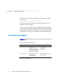
Command Descriptions . . . . . . . . . . . . . . . . . . . . . . . . . . . . . . . . . . . . . . . . . . . . . . . . . . . . . . . . . . . . . . . . . . . 3-2
addr . . . . . . . . . . . . . . . . . . . . . . . . . . . . . . . . . . . . . . . . . . . . . . . . . . . . . . . . . . . . . . . . . . . . . . . . . . . . . . . . . 3-5
boot . . . . . . . . . . . . . . . . . . . . . . . . . . . . . . . . . . . . . . . . . . . . . . . . . . . . . . . . . . . . . . . . . . . . . . . . . . . . . . . . . 3-8
config. . . . . . . . . . . . . . . . . . . . . . . . . . . . . . . . . . . . . . . . . . . . . . . . . . . . . . . . . . . . . . . . . . . . . . . . . . . . . . . 3-13
console-baud . . . . . . . . . . . . . . . . . . . . . . . . . . . . . . . . . . . . . . . . . . . . . . . . . . . . . . . . . . . . . . . . . . . . . . . . 3-14
erase . . . . . . . . . . . . . . . . . . . . . . . . . . . . . . . . . . . . . . . . . . . . . . . . . . . . . . . . . . . . . . . . . . . . . . . . . . . . . . . 3-16
help . . . . . . . . . . . . . . . . . . . . . . . . . . . . . . . . . . . . . . . . . . . . . . . . . . . . . . . . . . . . . . . . . . . . . . . . . . . . . . . . 3-18
image . . . . . . . . . . . . . . . . . . . . . . . . . . . . . . . . . . . . . . . . . . . . . . . . . . . . . . . . . . . . . . . . . . . . . . . . . . . . . . 3-19
ipx. . . . . . . . . . . . . . . . . . . . . . . . . . . . . . . . . . . . . . . . . . . . . . . . . . . . . . . . . . . . . . . . . . . . . . . . . . . . . . . . . . 3-20
lat_key . . . . . . . . . . . . . . . . . . . . . . . . . . . . . . . . . . . . . . . . . . . . . . . . . . . . . . . . . . . . . . . . . . . . . . . . . . . . . . 3-21
mop . . . . . . . . . . . . . . . . . . . . . . . . . . . . . . . . . . . . . . . . . . . . . . . . . . . . . . . . . . . . . . . . . . . . . . . . . . . . . . . . 3-22
net . . . . . . . . . . . . . . . . . . . . . . . . . . . . . . . . . . . . . . . . . . . . . . . . . . . . . . . . . . . . . . . . . . . . . . . . . . . . . . . . . 3-23
option_key. . . . . . . . . . . . . . . . . . . . . . . . . . . . . . . . . . . . . . . . . . . . . . . . . . . . . . . . . . . . . . . . . . . . . . . . . . . 3-25
ping . . . . . . . . . . . . . . . . . . . . . . . . . . . . . . . . . . . . . . . . . . . . . . . . . . . . . . . . . . . . . . . . . . . . . . . . . . . . . . . . 3-26
ports . . . . . . . . . . . . . . . . . . . . . . . . . . . . . . . . . . . . . . . . . . . . . . . . . . . . . . . . . . . . . . . . . . . . . . . . . . . . . . . . 3-27
sequence . . . . . . . . . . . . . . . . . . . . . . . . . . . . . . . . . . . . . . . . . . . . . . . . . . . . . . . . . . . . . . . . . . . . . . . . . . . 3-28
stats . . . . . . . . . . . . . . . . . . . . . . . . . . . . . . . . . . . . . . . . . . . . . . . . . . . . . . . . . . . . . . . . . . . . . . . . . . . . . . . . 3-29
Chapter 4
Troubleshooting Procedures
Power-up and Boot Procedures. . . . . . . . . . . . . . . . . . . . . . . . . . . . . . . . . . . . . . . . . . . . . . . . . . . . . . . . . . . . . 4-4
Normal Mode Remote Annex 6300 Diagnostics. . . . . . . . . . . . . . . . . . . . . . . . . . . . . . . . . . . . . . . . . . . . . 4-5
Setup Mode . . . . . . . . . . . . . . . . . . . . . . . . . . . . . . . . . . . . . . . . . . . . . . . . . . . . . . . . . . . . . . . . . . . . . . . . . . 4-7
Boot Failures . . . . . . . . . . . . . . . . . . . . . . . . . . . . . . . . . . . . . . . . . . . . . . . . . . . . . . . . . . . . . . . . . . . . . . . . . . . . 4-10
Boot Error Report . . . . . . . . . . . . . . . . . . . . . . . . . . . . . . . . . . . . . . . . . . . . . . . . . . . . . . . . . . . . . . . . . . . . . 4-11
Correcting Remote Annex 6300 Parameters . . . . . . . . . . . . . . . . . . . . . . . . . . . . . . . . . . . . . . . . . . . . . . 4-13
Load Server Host Not Responding . . . . . . . . . . . . . . . . . . . . . . . . . . . . . . . . . . . . . . . . . . . . . . . . . . . . . . . 4-14
Remote Annex 6300 Dumps . . . . . . . . . . . . . . . . . . . . . . . . . . . . . . . . . . . . . . . . . . . . . . . . . . . . . . . . . . . . . . 4-17
Appendix A
Port Pins and Signals
Console Port . . . . . . . . . . . . . . . . . . . . . . . . . . . . . . . . . . . . . . . . . . . . . . . . . . . . . . . . . . . . . . . . . . . . . . . . . . . . .
10Base2 Ethernet Port . . . . . . . . . . . . . . . . . . . . . . . . . . . . . . . . . . . . . . . . . . . . . . . . . . . . . . . . . . . . . . . . . . . . .
10Base5 Ethernet Port . . . . . . . . . . . . . . . . . . . . . . . . . . . . . . . . . . . . . . . . . . . . . . . . . . . . . . . . . . . . . . . . . . . . .
10BaseT Ethernet Port . . . . . . . . . . . . . . . . . . . . . . . . . . . . . . . . . . . . . . . . . . . . . . . . . . . . . . . . . . . . . . . . . . . . .
PRI ISDN Interface . . . . . . . . . . . . . . . . . . . . . . . . . . . . . . . . . . . . . . . . . . . . . . . . . . . . . . . . . . . . . . . . . . . . . . . .
Appendix B
A-1
A-2
A-3
A-4
A-5
Connectors and Jumpers
Loopback Connectors . . . . . . . . . . . . . . . . . . . . . . . . . . . . . . . . . . . . . . . . . . . . . . . . . . . . . . . . . . . . . . . . . . . . B-1
Appendix C Modem Carrier Card
Upgrade Instructions
Contents of the Kit . . . . . . . . . . . . . . . . . . . . . . . . . . . . . . . . . . . . . . . . . . . . . . . . . . . . . . . . . . . . . . . . . . . . . . . .
Required Tools. . . . . . . . . . . . . . . . . . . . . . . . . . . . . . . . . . . . . . . . . . . . . . . . . . . . . . . . . . . . . . . . . . . . . . . .
Disassembly Instructions . . . . . . . . . . . . . . . . . . . . . . . . . . . . . . . . . . . . . . . . . . . . . . . . . . . . . . . . . . . . . . . . . . .
Installation Instructions. . . . . . . . . . . . . . . . . . . . . . . . . . . . . . . . . . . . . . . . . . . . . . . . . . . . . . . . . . . . . . . . . . . . .
Assembly Instructions . . . . . . . . . . . . . . . . . . . . . . . . . . . . . . . . . . . . . . . . . . . . . . . . . . . . . . . . . . . . . . . . . . . . . .
Power-up and Test . . . . . . . . . . . . . . . . . . . . . . . . . . . . . . . . . . . . . . . . . . . . . . . . . . . . . . . . . . . . . . . . . . . . . . . .
Appendix D
C-1
C-1
C-2
C-3
C-5
C-6
Modem Upgrade Instructions
Contents of the Kit . . . . . . . . . . . . . . . . . . . . . . . . . . . . . . . . . . . . . . . . . . . . . . . . . . . . . . . . . . . . . . . . . . . . . . . . D-1
x
Remote Annex 6300 Hardware Installation Guide
Contents
Required Tools . . . . . . . . . . . . . . . . . . . . . . . . . . . . . . . . . . . . . . . . . . . . . . . . . . . . . . . . . . . . . . . . . . . . . . . .
Disassembly Instructions. . . . . . . . . . . . . . . . . . . . . . . . . . . . . . . . . . . . . . . . . . . . . . . . . . . . . . . . . . . . . . . . . . . .
Installation Instructions . . . . . . . . . . . . . . . . . . . . . . . . . . . . . . . . . . . . . . . . . . . . . . . . . . . . . . . . . . . . . . . . . . . . .
Assembly Instructions . . . . . . . . . . . . . . . . . . . . . . . . . . . . . . . . . . . . . . . . . . . . . . . . . . . . . . . . . . . . . . . . . . . . . .
Power-up and Test . . . . . . . . . . . . . . . . . . . . . . . . . . . . . . . . . . . . . . . . . . . . . . . . . . . . . . . . . . . . . . . . . . . . . . . .
Removing Quad Modem Cards. . . . . . . . . . . . . . . . . . . . . . . . . . . . . . . . . . . . . . . . . . . . . . . . . . . . . . . . . . . . .
Remote Annex 6300 Hardware Installation Guide
D-1
D-2
D-3
D-5
D-6
D-7
xi
Contents
xii
Remote Annex 6300 Hardware Installation Guide
Figures
Figure 1-1. The Remote Annex 6300 as a Remote Access Server . . . . . . . . . . . . . . . . . . . . . . . . . . . . . . . . . . 1-1
Figure 1-2. Remote Annex 6300 . . . . . . . . . . . . . . . . . . . . . . . . . . . . . . . . . . . . . . . . . . . . . . . . . . . . . . . . . . . . . 1-2
Figure 1-3. Remote Annex 6300 Front Panel . . . . . . . . . . . . . . . . . . . . . . . . . . . . . . . . . . . . . . . . . . . . . . . . . . . 1-5
Figure 1-4. Remote Annex 6300 Rear Panel. . . . . . . . . . . . . . . . . . . . . . . . . . . . . . . . . . . . . . . . . . . . . . . . . . . . 1-9
Figure 2-1. Attaching the Mounting Bracket to the Remote Annex 6300 . . . . . . . . . . . . . . . . . . . . . . . . . . . 2-3
Figure 2-2. Attaching the Mounting Bracket and Device to the Rack . . . . . . . . . . . . . . . . . . . . . . . . . . . . . . 2-4
Figure 2-3. Attaching the Mounting Bracket to the Remote Annex 6300 . . . . . . . . . . . . . . . . . . . . . . . . . . . 2-5
Figure 2-4. Attaching the Mounting Bracket and Device to the Rack . . . . . . . . . . . . . . . . . . . . . . . . . . . . . . 2-6
Figure 2-5. Remote Annex 6300 Ethernet Connections . . . . . . . . . . . . . . . . . . . . . . . . . . . . . . . . . . . . . . . . . . 2-7
Figure 2-6. Connecting Thin Ethernet Cable . . . . . . . . . . . . . . . . . . . . . . . . . . . . . . . . . . . . . . . . . . . . . . . . . . . 2-8
Figure 2-7. Connecting Thick Ethernet Cable . . . . . . . . . . . . . . . . . . . . . . . . . . . . . . . . . . . . . . . . . . . . . . . . . . 2-9
Figure 2-8. Connecting Twisted Pair Ethernet Cable . . . . . . . . . . . . . . . . . . . . . . . . . . . . . . . . . . . . . . . . . . . 2-10
Figure 2-9. Connecting the Cable to the DB-25 DTE Drop Adapter . . . . . . . . . . . . . . . . . . . . . . . . . . . . . . . 2-11
Figure 2-10. Connecting a Console Terminal . . . . . . . . . . . . . . . . . . . . . . . . . . . . . . . . . . . . . . . . . . . . . . . . . 2-12
Figure 2-11. Connecting the PRI ISDN Interface . . . . . . . . . . . . . . . . . . . . . . . . . . . . . . . . . . . . . . . . . . . . . . . 2-13
Figure 2-12. Verifying the Remote Annex 6300 Operational Power Range . . . . . . . . . . . . . . . . . . . . . . . . . 2-14
Figure 2-13. Connecting the Power Cord . . . . . . . . . . . . . . . . . . . . . . . . . . . . . . . . . . . . . . . . . . . . . . . . . . . . 2-15
Figure 4-1. Remote Annex 6300 Front Panel Alarms and LEDs. . . . . . . . . . . . . . . . . . . . . . . . . . . . . . . . . . . . . 4-1
Figure A-1. Console Port. . . . . . . . . . . . . . . . . . . . . . . . . . . . . . . . . . . . . . . . . . . . . . . . . . . . . . . . . . . . . . . . . . . A-1
Figure A-2. 10Base2 BNC Ethernet Port . . . . . . . . . . . . . . . . . . . . . . . . . . . . . . . . . . . . . . . . . . . . . . . . . . . . . . A-2
Figure A-3. 10Base5 Ethernet Port . . . . . . . . . . . . . . . . . . . . . . . . . . . . . . . . . . . . . . . . . . . . . . . . . . . . . . . . . . . A-3
Figure A-4. 10BaseT Ethernet Port . . . . . . . . . . . . . . . . . . . . . . . . . . . . . . . . . . . . . . . . . . . . . . . . . . . . . . . . . . . A-4
Figure A-5. PRI ISDN Interface Port Receptacle . . . . . . . . . . . . . . . . . . . . . . . . . . . . . . . . . . . . . . . . . . . . . . . A-5
Figure C-1. Removing the Remote Annex 6300 Cover. . . . . . . . . . . . . . . . . . . . . . . . . . . . . . . . . . . . . . . . . . C-2
Figure C-2. Adding Modem Carrier Card to the Remote Annex 6300. . . . . . . . . . . . . . . . . . . . . . . . . . . . . C-4
Figure C-3. Replacing the Remote Annex 6300 Cover . . . . . . . . . . . . . . . . . . . . . . . . . . . . . . . . . . . . . . . . . C-5
Figure C-4. Setting the Remote Annex 6300 to Test Mode . . . . . . . . . . . . . . . . . . . . . . . . . . . . . . . . . . . . . . C-6
Figure D-1. Removing the Remote Annex 6300 Cover . . . . . . . . . . . . . . . . . . . . . . . . . . . . . . . . . . . . . . . . . . D-2
Figure D-2. Adding Modem Cards to the Remote Annex 6300 . . . . . . . . . . . . . . . . . . . . . . . . . . . . . . . . . . D-4
Figure D-3. Replacing the Remote Annex 6300 Cover. . . . . . . . . . . . . . . . . . . . . . . . . . . . . . . . . . . . . . . . . . D-5
Figure D-4. Setting the Remote Annex 6300 to Test Mode. . . . . . . . . . . . . . . . . . . . . . . . . . . . . . . . . . . . . . . D-6
Figure D-5. Removing Modem Cards from the Remote Annex 6300 . . . . . . . . . . . . . . . . . . . . . . . . . . . . . . D-9
Figure D-6. Locating and Setting DIP Switch S1. . . . . . . . . . . . . . . . . . . . . . . . . . . . . . . . . . . . . . . . . . . . . . . D-10
Remote Annex 6300 Hardware Installation Guide
xiii
Tables
Table 1-1. Modem Port Status LEDs. . . . . . . . . . . . . . . . . . . . . . . . . . . . . . . . . . . . . . . . . . . . . . . . . . . . . . . . .
Table 1-2. Network/Status Alarms . . . . . . . . . . . . . . . . . . . . . . . . . . . . . . . . . . . . . . . . . . . . . . . . . . . . . . . . . .
Table 2-1. Remote Annex 6300 Configuration Options . . . . . . . . . . . . . . . . . . . . . . . . . . . . . . . . . . . . . . . .
Table 3-1. ROM Monitor Commands . . . . . . . . . . . . . . . . . . . . . . . . . . . . . . . . . . . . . . . . . . . . . . . . . . . . . . .
Table 3-2. Network Statistics . . . . . . . . . . . . . . . . . . . . . . . . . . . . . . . . . . . . . . . . . . . . . . . . . . . . . . . . . . . . .
Table 4-1. Remote Annex 6300 Front Panel LEDs . . . . . . . . . . . . . . . . . . . . . . . . . . . . . . . . . . . . . . . . . . . . .
Table 4-2. Normal Mode Error-free LED States . . . . . . . . . . . . . . . . . . . . . . . . . . . . . . . . . . . . . . . . . . . . . . . .
Table 4-3. Normal Mode Error LED States. . . . . . . . . . . . . . . . . . . . . . . . . . . . . . . . . . . . . . . . . . . . . . . . . . . .
Table 4-4. Normal Mode Error LED States. . . . . . . . . . . . . . . . . . . . . . . . . . . . . . . . . . . . . . . . . . . . . . . . . . . .
Table 4-5. Normal Mode Error LED States. . . . . . . . . . . . . . . . . . . . . . . . . . . . . . . . . . . . . . . . . . . . . . . . . . . .
Table 4-6. Errors from Last ERPC Layer Invocation. . . . . . . . . . . . . . . . . . . . . . . . . . . . . . . . . . . . . . . . . . . .
Table 4-7. Errors from Last Read Request . . . . . . . . . . . . . . . . . . . . . . . . . . . . . . . . . . . . . . . . . . . . . . . . . . .
Table 4-8. Errors from Last Open Request . . . . . . . . . . . . . . . . . . . . . . . . . . . . . . . . . . . . . . . . . . . . . . . . . .
Table 4-9. Remote Annex 6300 LED States During a Dump . . . . . . . . . . . . . . . . . . . . . . . . . . . . . . . . . . . .
Table 4-10. Remote Annex 6300 Dump File Naming Conventions . . . . . . . . . . . . . . . . . . . . . . . . . . . . . .
Table A-1. Console Port Pin/Signal Allocations . . . . . . . . . . . . . . . . . . . . . . . . . . . . . . . . . . . . . . . . . . . . . . .
Table A-2. 10Base5 Ethernet Port Pin/Signal Allocation . . . . . . . . . . . . . . . . . . . . . . . . . . . . . . . . . . . . . . . .
Table A-3. 10BaseT Ethernet Port Pin/Signal Allocations . . . . . . . . . . . . . . . . . . . . . . . . . . . . . . . . . . . . . . .
Table A-4. PRI ISDN Interface Port/Pin Signal Allocations. . . . . . . . . . . . . . . . . . . . . . . . . . . . . . . . . . . . . . .
Table B-1. 10Base5 Ethernet Loopback Connector . . . . . . . . . . . . . . . . . . . . . . . . . . . . . . . . . . . . . . . . . . .
Table B-2. 10BaseT Ethernet Loopback Connector Wiring . . . . . . . . . . . . . . . . . . . . . . . . . . . . . . . . . . . . .
Table D-1. Modem Card/S1 DIP Switch Section Assignments . . . . . . . . . . . . . . . . . . . . . . . . . . . . . . . . . . .
xiv
Remote Annex 6300 Hardware Installation Guide
1-6
1-7
2-1
3-2
3-29
4-2
4-5
4-6
4-8
4-9
4-12
4-12
4-13
4-17
4-19
A-2
A-3
A-4
A-5
B-1
B-1
D-8
Preface
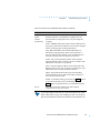
T
his guide describes what a network administrator needs to know
to install a Remote Annex 6300 on a local area network (LAN).
The Remote Annex Software Installation Notes describe how to install
the software. The Annex Administrator’s Guide for UNIX provides
configuration information.
About this Guide
This guide includes the following chapters and appendices:
Chapter 1 Introduction
This chapter contains an overview of the Remote
Annex 6300; it describes the hardware features and
firmware functions.
Chapter 2 Installing the Remote Annex 6300
This chapter describes how to install
the Remote Annex 6300 on a LAN, and how to
confirm its operating status.
Chapter 3 ROM Monitor Commands
This chapter describes the ROM
Monitor commands that modify specific
configuration parameters, perform diagnostic tests,
and load the operational code.
Chapter 4 Troubleshooting Procedures
This chapter provides troubleshooting and
verification procedures.
Remote Annex 6300 Hardware Installation Guide
xv
Preface
Appendix A
Port Pins and Signals
This appendix details the connectors located on the
rear panel of the Remote Annex 6300.
Appendix B
Connectors and Jumpers
This appendix describes the loopback
connectors and jumper settings for the Remote
Annex 6300.
Appendix C
Modem Carrier Card Upgrade Instructions
This appendix describes how to install the modem
carrier card into the Remote Annex 6300.
Appendix D
Modem Upgrade Instructions
This appendix describes how to install additional
modem cards into the Remote Annex 6300.
Printing Conventions
This manual uses the following printing conventions:
Convention:
Represents:
special type
In examples, special type indicates system output.
special type
Bold special type indicates user input.
Return
xvi
In command examples, this notation indicates that
pressing Return enters the default value.
Remote Annex 6300 Hardware Installation Guide
Preface
Convention:
Represents:
bold
Bold indicates commands, pathnames, or filenames
that must be entered as displayed.
italics
In the context of commands and command syntax,
lowercase italics indicate variables for which the user
supplies a value.
[]
In command dialogue, square brackets indicate default
values. Pressing Return selects this value. Square
brackets appearing in command syntax indicate
optional arguments.
{}
In command syntax, braces indicate that one, and only
one, of the enclosed value must be entered.
|
In command syntax, this character separates the
different options available for a parameter.
Notes give you important information.
Warnings inform you about conditions that can have
adverse effects on processing.
Cautions notify you about dangerous conditions.
Remote Annex 6300 Hardware Installation Guide
xvii
Preface
Related Documents
Each Remote Annex hardware platform ships with the appropriate
hardware guide. The remaining documentation is included with the
software.
xviii
Remote Annex 6300 Hardware Installation Guide
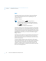
Technical Support and Online Services
T
o ensure comprehensive network support to our customers and
partners worldwide, Bay Networks Customer Service has Technical
Response Centers in key locations around the globe:
❑
Billerica, Massachusetts
❑
Santa Clara, California
❑
Sydney, Australia
❑
Tokyo, Japan
❑
Valbonne, France
The Technical Response Centers are connected via a redundant Frame
Relay Network to a Common Problem Resolution system, enabling
them to transmit and share information, and to provide live, aroundthe-clock support 365 days a year.
Bay Networks Information Services complement the Bay Networks
Service program portfolio by giving customers and partners access
to the most current technical and support information through a
choice of access/retrieval means. These include the World Wide Web,
CompuServe, Support Source CD, Customer Support FTP, and
InfoFACTS document fax service.
Bay Networks Customer Service
If you purchased your Bay Networks product from a distributor or
authorized reseller, contact that distributor’s or reseller’s technical
support staff for assistance with installation, configuration,
troubleshooting, or integration issues.
Remote Annex 6300 Hardware Installation Guide
xix
Technical Support and Online Services
Customers can also purchase direct support from Bay Networks
through a variety of service programs. As part of our PhonePlus™
program, Bay Networks Service sets the industry standard, with 24hour, 7-days-a-week telephone support available worldwide at no
extra cost. Our complete range of contract and noncontract services
also includes equipment staging and integration, installation support,
on-site services, and replacement parts delivery -- within
approximately 4 hours.
To purchase any of the Bay Networks support programs, or if you
have questions on program features, use the following numbers:
Region
Telephone Number
Fax Number
United States
and Canada
1-800-2LANWAN; enter Express
Routing Code (ERC) 290 when
prompted
(508) 670-8766
(508) 436-8880 (direct)
Europe
(33) 92-968-300
(33) 92-968-301
Asia/Pacific
Region
(612) 9927-8800
(612) 9927-8811
Latin America
(407) 997-1713
(407) 997-1714
In addition, you can receive information on support programs from
your local Bay Networks field sales office, or purchase Bay Networks
support directly from your authorized partner.
xx
Remote Annex 6300 Hardware Installation Guide
Technical Support and Online Services
Bay Networks Information Services
Bay Networks Information Services provide up-to-date support
information as a first-line resource for network administration,
expansion, and maintenance. This information is available from a
variety of sources.
World Wide Web
The Bay Networks Customer Support Web Server offers a diverse
library of technical documents, software agents, and other important
technical information to Bay Networks customers and partners.
A special benefit for contracted customers and resellers is the ability
to access the Web Server to perform Case Management. This feature
enables your support staff to interact directly with the network
experts in our worldwide Technical Response Centers. A registered
contact with a valid Site ID can:
❑
View a listing of support cases and determine the current
status of any open case. Case history data includes severity
designation, and telephone, e-mail, or other logs associated
with the case.
❑
Customize the listing of cases according to a variety of
criteria, including date, severity, status, and case ID.
❑
Log notes to existing open cases.
❑
Create new cases for rapid, efficient handling of noncritical
network situations.
❑
Communicate directly via e-mail with the specific technical
resources assigned to your case.
The Bay Networks URL is http://www.baynetworks.com. Customer
Service is a menu item on that home page.
Remote Annex 6300 Hardware Installation Guide
xxi
Technical Support and Online Services
Customer Service FTP
Accessible via URL ftp://support.baynetworks.com (134.177.3.26), this
site combines and organizes support files and documentation from
across the Bay Networks product suite, including switching products
from our Centillion™ and Xylogics® business units. Central
management and sponsorship of this FTP site lets you quickly locate
information on any of your Bay Networks products.
Support Source CD
This CD-ROM -- sent quarterly to all contracted customers -- is a
complete Bay Networks Service troubleshooting knowledge database
with an intelligent text search engine.
The Support Source CD contains extracts from our problem-tracking
database; information from the Bay Networks Forum on
CompuServe; comprehensive technical documentation, such as
Customer Support Bulletins, Release Notes, software patches and
fixes; and complete information on all Bay Networks Service
programs.
You can run a single version on Macintosh, Windows 3.1,
Windows 95, Windows NT, DOS, or UNIX computing platforms. A
Web links feature enables you to go directly from the CD to various
Bay Networks Web pages.
CompuServe
For assistance with noncritical network support issues, Bay Networks
Information Services maintain an active forum on CompuServe, a
global bulletin-board system. This forum provides file services,
technology conferences, and a message section to get assistance from
other users.
xxii
Remote Annex 6300 Hardware Installation Guide
Technical Support and Online Services
The message section is monitored by Bay Networks engineers, who
provide assistance wherever possible. Customers and resellers
holding Bay Networks service contracts also have access to special
libraries for advanced levels of support documentation and software.
To take advantage of CompuServe’s recently enhanced menu options,
the Bay Networks Forum has been re-engineered to allow links to our
Web sites and FTP sites.
We recommend the use of CompuServe Information Manager
software to access these Bay Networks Information Services
resources. To open an account and receive a local dial-up number in
the United States, call CompuServe at 1-800-524-3388. Outside the
United States, call 1-614-529-1349, or your nearest CompuServe office.
Ask for Representative No. 591. When you are on line with your
CompuServe account, you can reach us with the command GO
BAYNET.
InfoFACTS
InfoFACTS is the Bay Networks free 24-hour fax-on-demand service.
This automated system has libraries of technical and product
documents designed to help you manage and troubleshoot your Bay
Networks products. The system responds to a fax from the caller or
to a third party within minutes of being accessed.
To use InfoFACTS in the United States or Canada, call toll-free 1-800786-3228. Outside North America, toll calls can be made to 1-408-7641002. In Europe, toll-free numbers are also available for contacting
both InfoFACTS and CompuServe. Please check our Web page for the
listing in your country.
Remote Annex 6300 Hardware Installation Guide
xxiii
Technical Support and Online Services
How to Get Help
Use the following numbers to reach your Bay Networks Technical
Response Center:
xxiv
Technical Response Center
Telephone Number
Fax Number
Billerica, MA
1-800-2LANWAN
(508) 670-8765
Santa Clara, CA
1-800-2LANWAN
(408) 764-1188
Valbonne, France
(33) 92-968-968
(33) 92-966-998
Sydney, Australia
(612) 9927-8800
(612) 9927-8811
Tokyo, Japan
(81) 3-5402-0180
(81) 3-5402-0173
Remote Annex 6300 Hardware Installation Guide
Chapter 1
Introduction
T
he Remote Annex 6300 is a dial-in remote access server that
supports mixed traffic, such as analog modems, V.120 ISDN Terminal
Adapters, and devices supporting synchronous PPP.
Remote Network Access
The Remote Annex 6300 provides remote network access to the
following networks (see Figure 1-1):
❑
Novell Netware
❑
TCP/IP
❑
AppleTalk
DEC
IBM
UNIX
Corporate LAN
Ethernet
Remote
Annex 6300
Novell
Server
Apple
Macintosh
Primary Rate
ISDN Line
Central
Office
Up to 30 Analog, V.120, or
Synchronous PPP Lines
Figure 1-1. The Remote Annex 6300 as a Remote Access Server
Remote Annex 6300 Hardware Installation Guide
1-1
Chapter 1
Introduction
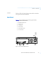
Remote Annex 6300 Description
The Remote Annex 6300 is a Primary Rate ISDN server that houses
up to 32 modems to provide the flexibility of terminating calls
originated by analog modems, terminal adapters, and routers.
Figure 1-2 illustrates a Remote Annex 6300.
Remote Annex 6300
Modem Config
Status
13-16 9-12
Modem Status
Bay Networks
32
31
30
29
28
27
26
25
24
23
22
21
20
19
18
17
16
15
14
13
5-8
1-4
29-32 25-28 21-24 17-20
12
11
10
9
8
7
6
5
4
3
2
1
CD
Tx/Rx
Xylogics, a Bay Networks Company
Network/Status
Ararms
Test Sync Los
PRI Channel Status
32
31
30
29
28
27
26
25
24
23
22
21
20
19
18
17
16
15
14
13
12
11
10
9
8
7
6
5
4
3
2
1
Red
Yel
Stat
Blu
Attn
Traf
Setup Power
Reset
Figure 1-2. Remote Annex 6300
The Remote Annex 6300 contains two main boards:
❑
Main Logic Board (MLB)
❑
Modem Carrier Card
The Remote Annex 6300 complies with the Ethernet Revision 2.0 or
the IEEE 802.3 specifications using standard Ethernet 10Base2 (Thin),
10Base5 (Thick), and 10BaseT (Twisted Pair) as the physical medium.
Main Logic Board
Processor
The Remote Annex 6300 main logic board (MLB) utilizes two 80486
DX2, 64-Mhz, clock-doubled processors.
Ethernet Interfaces
The MLB provides 10Base2, 10Base5, and 10BaseT autosensed
Ethernet interfaces.
1-2
Remote Annex 6300 Hardware Installation Guide
Chapter 1
Introduction
PRI Interface
This interface resides on the MLB in the form of a module whose RJ45
connector is accessible through the rear panel of the Remote Annex
6300. This interface is controlled by a second 486DX2 processor, whch
also controls the internal modems.
Memory
The MLB has 8 megabytes of main DRAM, and an additional 4
megabytes of DRAM is used by the PRI interface controller.
Flash Memory
The MLB supports 2 megabytes of Flash memory.
Modem Carrier Card
Modems
The Remote Annex 6300 can be configured with 0, 4, 8, 12, 16, 24, or
32 internal V.34 modems. The modems, located on quad modem
cards, are installed on the Modem Carrier Card. The modems receive
data from a TTL serial channel and convert the data to a modulated
analog waveform. The analog signal is then presented to a pulse-codemodulated coder/decoder (PCM codec).
PCM Codec
The Remote Annex 6300 uses PCM codecs to convert the analog
signals coming from the modems into 8-bit serial data streams. The
data streams are multiplexed and passed to the PRI interface along
with data that is purely digital in nature, such as that used with V.120
and synchronous PPP protocols.
Firmware and Software
Firmware
The Remote Annex 6300’s ROM contains firmware for performing
power-up self-tests and loading operational code. A non-volatile
EEPROM stores the configuration parameters.
The Remote Annex 6300 can have a boot image in Flash ROM or can
receive its image from a device on the network; this image is used to
boot the Remote Annex 6300.
Remote Annex 6300 Hardware Installation Guide
1-3
Chapter 1
Introduction
ROM Monitor
When the Remote Annex completes its self tests, the console displays
the ROM monitor prompt. The ROM monitor is an interactive
command interpreter that is used to define configuration parameters.
All of the information that the Remote Annex needs to boot an
operational image is defined using the ROM monitor and its
command set. ROM Monitor commands are issued from a console
terminal connected to the console port on the Remote Annex’s front
panel. Using the ROM Monitor commands (see Chapter 3), you can:
❑
Modify and display a set of configuration parameters stored
in EEPROM
❑
Execute interactive diagnostic tests
❑
Receive information and statistics for the hardware
configuration and the network
❑
Boot the Remote Annex 6300 manually
Once the Remote Annex 6300 has obtained a boot image and is booted,
the console leaves the ROM monitor and displays the console monitor.
(for more details, see Chapter 2).
Supported
Configurations
Watchdog Timer
1-4
You can self-boot the Remote Annex 6300 from its Flash ROM, and
you can obtain full operational code over the network from one of the
following devices:
❑
UNIX host
❑
Remote Annex 6300 configured as a load server
The Remote Annex 6300 has a watchdog timer that its software resets
at regular intervals. The watchdog timer reboots the Remote Annex
6300 in the unlikely event of an internal software error. This feature
enables the Remote Annex 6300 to run for long periods of time
without intervention.
Remote Annex 6300 Hardware Installation Guide
Chapter 1
Introduction
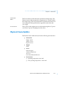
Front Panel
The Remote Annex 6300 front panel consists of:
❑
Modem Port Status LEDs
❑
Modem Configuration Status LEDs
❑
PRI Channel Status LEDs
❑
Network /Status Alarms
❑
Reset Button
❑
Power LED
Figure 1-3 illustrates the Remote Annex 6300 front panel. The front
panel components are described in the following paragraphs.
Modem Port
Status LEDs
Modem Config
Status LEDs
Remote Annex 6300
Modem Config
Status
13-16 9-12
Modem Status
Bay Networks
32
31
30
29
28
27
26
25
24
23
22
21
20
19
18
17
16
15
14
13
5-8
1-4
29-32 25-28 21-24 17-20
12
11
10
9
8
7
6
5
4
3
2
1
CD
Tx/Rx
Xylogics, a Bay Networks Company
Network/Status
Ararms
Test Sync Los
PRI Channel Status
32
31
30
29
28
27
26
25
24
23
22
21
20
19
PRI Channel
Status LEDs
18
17
16
15
14
13
12
11
10
9
8
7
6
5
4
3
2
1
Red
Yel
Stat
Blu
Attn
Traf
Setup Power
Reset
Network
Status Alarms
Figure 1-3. Remote Annex 6300 Front Panel
Remote Annex 6300 Hardware Installation Guide
1-5
Chapter 1
Introduction
Front Panel Components
Modem Port
Status LEDs
The Remote Annex 6300 has two status LEDs for each modem port
(up to 32, if installed). The status LEDs display modem port status
during system operation. Table 1-1 describes the modem port status
LEDs.
Table 1-1. Modem Port Status LEDs
LED
Description
CD
CD (Data Carrier Detect) LED is green and ON when carrier has
been detected by the corresponding modem. There are 32 CD
LEDs, one LED per channel, on the front of the Remote Annex
6300.
TX/RX
TX/RX LED is green and flashes to indicate the corresponding
modem is transmitting or receiving data. There are 32 TX/RX
LEDs, one LED per channel, on the front of the Remote Annex
6300. For North American models, up to 32 modems can be
installed (although only 23 are active at any given time). For
European countries that use E1 lines for PRI access, a maximum
of 32 modems can be installed (only 30 are active at any given
time).
Modem Config
Status LEDs
The Modem Config Status LEDs indicate the number of modems
installed. An LED is green if all the modems in its group are good. An
LED is amber if one or more modems in its group are bad.
PRI Channel
Status LEDs
The PRI Channel Status LEDs indicate B channel allocation. There are
32 PRI Channel Status LEDs on the front of the Remote Annex 6300.
For T1, 23 are used to indicate B channel allocation. For E1, 30 are used
for B channel allocation.
1-6
Remote Annex 6300 Hardware Installation Guide
Chapter 1
Network/Status
Alarms
Introduction
The six Network/Status Alarms, labeled RED, YEL, BLU, TEST,
SYNC, and LOS, display PRI network activity during system
operation. The front panel also has four system status LEDs labeled
ATTN, STAT, TRAF, and STATUS that display operational status
conditions for the Remote Annex 6300. Table 1-2 describes the alarms.
Technical Support personnel can use this information to diagnose
problems.
If you are using an external CSU, some of the Network/Status
alarm LEDs may not give true readings. In this case, defer to
the status and alarm conditions indicated on the external CSU.
Table 1-2. Network/Status Alarms
Alarm
Description
RED
RED alarm LED is ON during a locally detected carrier failure.
During the RED alarm condition, a YELLOW alarm is
transmitted across the telephone network.
YEL
YELLOW alarm LED is ON when receiving a YELLOW alarm
condition from the telephone network.
BLU
BLUE alarm LED is ON when receiving an unframed, all-ones
Alarm Indication Signal (AIS) from the network. This condition
exists upon a loss of originating signal, or when any action is
taken that would cause a signal disruption.
TEST
RED network TEST LED is ON when the ISDN Network
Interface is looped back. Loopback tests are activated either
locally by the user or by the telephone company.
SYNC
GREEN SYNC LED is ON when the PRI interface is properly
synchronized with the received network signal and is receiving
proper framing information.
(continued on next page)
Remote Annex 6300 Hardware Installation Guide
1-7
Chapter 1
Introduction
Table 1-2. Network/Status Alarms (continued)
Reset Button
1-8
Alarm
Description
LOS
RED LOS LED is ON when the PRI interface is detecting no
signal (pulses) on the network interface receiver. When a LOS
condition exists, the PRI interface transmits unframed all ones
(AIS) to the network.
ATTN
The ATTN (Attention) LED is amber and ON when the Remote
Annex 6300 requires operator attention. The LED is flashing
when there is a problem.
STAT
The STAT (Status) LED is green and ON after the Remote Annex
6300 passes the core power-up diagnostics. The LED flashes after
resetting the Remote Annex 6300.
TRAF
The TRAF (Traffic) LED is green and flashing when the Remote
Annex 6300 successfully transmits or receives data from the
LAN.
SETUP
The SETUP LED is green when the
(Setup mode) and flashing when the
for 3 seconds (Reset Mode).
The
Reset
Reset
Reset
button is pressed ON
button is pressed ON
button is used to:
❑
Enter Setup Mode.
When the Reset button is pressed (ON), the SETUP LED is
green and the Remote Annex 6300 enters Setup mode. In this
mode, configuration data is entered via the Console Terminal
prior to booting the operational software.
❑
Reset the Remote Annex 6300.
When the Reset button is pressed and held for 3 seconds,
the SETUP LED flashes and the Remote Annex 6300 begins
to execute its power-up diagnostics. If the Reset button is
depressed again within 5 to 10 seconds, the Remote Annex
6300 enters Setup mode and waits for configuration
information to be entered.
Remote Annex 6300 Hardware Installation Guide
Chapter 1
Power LED
Introduction
The Power LED is ON when the Remote Annex 6300 is connected to
an AC power source and switched ON.
Rear Panel
Figure 1-4 shows the Remote Annex 6300 rear panel with the
following connectors and switches:
❑
PRI ISDN Interface Port
❑
Ethernet Ports
❑
Console Port
❑
Power Switch
❑
Power Select Switch
❑
AC Line Socket
Power
Select
Switch
ISDN PRI
CONSOLE
10BASE5
10BASE2
115
Power
Switch
10BASET
LINK
Console
Port
Ethernet
Ports
ISDN Port
AC Line
Socket
Figure 1-4. Remote Annex 6300 Rear Panel
Remote Annex 6300 Hardware Installation Guide
1-9
Chapter 1
Introduction
Rear Panel Components
PRI ISDN
Interface Port
The PRI ISDN Interface port comes with an 8-pin, RJ48C port for
attaching the PRI ISDN Interface cable connector. The PRI ISDN
Interface provides access to a digital PRI ISDN line.
Ethernet Ports
The Remote Annex 6300 comes with auto-sensed 10Base2, 10Base5,
and 10BaseT Ethernet connectors. Connect to your LAN using one of
the following:
❑
10Base2 (Thin Ethernet) Ethernet port with a BNC connector.
❑
10Base5 (Thick Ethernet) Ethernet transceiver port with a
DB15 connector.
❑
10BaseT (Twisted Pair Ethernet) Ethernet port with an
RJ-45 connector.
A Link Indicator LED is provided. This LED is green when an active
10BaseT segment is attached.
Connect only one interface at a time.
The Remote Annex 6300 must be reset (hard reset) when
changing network interface connections.
Console Port
The Remote Annex 6300 has a 9600-baud console port with an
8-pin, modular jack for attaching the console. The console port
provides access to the ROM Monitor commands when the Remote
Annex 6300 is in test mode and provides access to the console
commands when the unit is running.
Power Switch
The Power switch disconnects AC power without disconnecting the
Remote Annex 6300 from the power source.
1-10
Remote Annex 6300 Hardware Installation Guide
Chapter 1
Introduction
Power Select
Switch
The Power Select switch selects the operational voltage range. The
Remote Annex 6300 automatically compensates for variation within
the voltage range. The 110V position allows operation in the 90 to 130
VAC range; the 220V position allows operation in the 180 to 260
VAC range.
AC Line Socket
The AC line socket supplies power to the unit through the AC power
cord. The AC power cord plugs into this socket.
Physical Characteristics
The Remote Annex 6300 enclosure has the following characteristics:
❑
Dimensions:
Height: 4.06 in.
Width: 17.25 in.
Depth: 16.75 in.
❑
Weight:
20 lbs.
❑
Power:
Internal supply.
100-120/220-240 VAC
4.0/2.0 A
60/50 Hz, 200W, 682 BTU/hr.
❑
Environment:
❑
Operating temperature: 0° to 50°C.
❑
Non-operating temperature: -25° to 65°C
Remote Annex 6300 Hardware Installation Guide
1-11
Chapter 1
Introduction
❑
❑
❑
Operating humidity: 5% to 95% relative humidity,
non-condensing
❑
Non-operating humidity: 5% to 95% relative humidity,
non-condensing
❑
Operating shock: 10G peak 1/2 sine wave, 11 ms
duration
❑
Operating vibration: random vibration 1.2 *10-3 G2/Hz,
12 to 198 Hz
❑
Operating altitude: 0 to 4,000 meters
❑
Storage altitude: 0 to 15,000 meters
❑
Transportation vibration and shock: NSTA project 1A
standard in shipping container
Approvals:
❑
Meets safety requirements of ETL, conforms to
ANSI/UL STD 1950, EN60950, and CSA C22.2 No. 950
❑
Meets EMI requirements of FCC Class A and EN55022
Class A with shielded and unshielded cables
❑
Meets Canadian Telcom requirements IC CS-03
MTBF:
50,000 hrs. (estimated), calculated @ 25°C (Mil Std 217)
❑
Rear clearance requirement (for connectors and cables):
6 in. (15 cm)
1-12
Remote Annex 6300 Hardware Installation Guide
Chapter 2
Installing the Remote Annex 6300
T
his chapter describes how to install your Remote Annex 6300
hardware and connect it to your Ethernet network. Setting up the
Remote Annex 6300 consists of:
❑
Installing the Remote Annex 6300 in a Rack (Optional)
❑
Connecting a LAN
❑
Connecting a Console Terminal
❑
Connecting a PRI ISDN Interface
❑
Powering Up and Testing the Remote Annex 6300
❑
Installing the Software and Loading the Operational Image
❑
Auto-initializing the ROMs
❑
Self-booting the Remote Annex 6300
❑
Invoking a Console Monitor
Before you Begin
The Remote Annex 6300’s software and operational image can be
installed on two different devices. Table 2-1 outlines the different
configurations the Remote Annex 6300 supports.
Table 2-1. Remote Annex 6300 Configuration Options
Device on which the Operational
Software and Image is installed
Remote Annex
6300 Must be
Connected to
the Network
Input Device used to
Enter Installation
Parameters
UNIX Load Host
Yes
Console
Remote Annex 6300 Flash ROM
(Self-booting)
No
Console
Remote Annex 6300 Hardware Installation Guide
2-1
Chapter 2
Installing the Remote Annex 6300
Connecting the Remote Annex to a LAN requires the following
equipment:
❑
The appropriate network cable (e.g., Ethernet transceiver
cable) for connecting to a LAN or an Ethernet loopback
connector.
❑
The console port cable (supplied with software) and a
console terminal.
Installing the Remote Annex 6300 in a Rack (Optional)
Installing the Remote Annex 6300 in a rack is optional and requires
the following equipment:
❑
Mounting brackets, front and back
❑
Hardware kit
❑
Phillips screwdriver
The following paragraphs contain a description of how to mount the
Remote Annex 6300 in a rack. The device can be mounted in two ways:
❑
Front Mount
❑
Rear Mount
Front Mount
The Remote Annex 6300 is mounted to the front of the rack by
attaching the front mounting bracket to the device and then attaching
the device and mounting bracket to the rack.
2-2
Remote Annex 6300 Hardware Installation Guide
Chapter 2
Installing the Remote Annex 6300
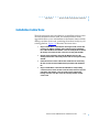
Attaching the Mounting Bracket to the Remote Annex 6300
Attach the front mounting bracket to the Remote Annex 6300 as
follows:
1
Remove the mounting bracket from its package.
2
Remove three screws from the front of the cover on each side of the
Remote Annex 6300, as shown in Figure 2-1. Save these screws; you
will need them later to install the front mounting bracket.
3
Install front mounting bracket to the device using the six screws
previously removed.
4
Tighten the screws to secure the bracket to the device.
Screws
(3 places each side)
Figure 2-1. Attaching the Mounting Bracket to the Remote Annex 6300
Remote Annex 6300 Hardware Installation Guide
2-3
Chapter 2
Installing the Remote Annex 6300
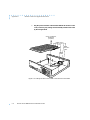
Attaching the Mounting Bracket and Device to the Rack
Attach the mounting bracket to the rack as follows:
1
Position the Remote Annex horizontally, facing forward in the rack.
2
Align the holes in the mounting bracket with the holes in the rack.
3
Insert the mounting screws and tighten the screws to attach the front
of the Remote Annex 6300 to the front rack (see Figure 2-2).
Remote Annex 6300
Modem Config
Status
13-16 9-12
Modem Status
Bay Networks
32
31
30
29
28
27
26
25
24
23
22
21
20
19
18
17
16
15
14
13
5-8
1-4
29-32 25-28 21-24 17-20
12
11
10
9
8
7
6
5
4
3
2
1
CD
Tx/Rx
Xylogics, a Bay Networks Company
Network/Status
Ararms
Test Sync Los
PRI Channel Status
32
31
30
29
28
27
26
25
24
23
22
21
20
19
18
17
16
15
14
13
12
11
10
9
8
7
6
5
4
3
2
1
Red
Yel
Stat
Blu
Attn
Traf
Setup Power
Reset
Figure 2-2. Attaching the Mounting Bracket and Device to the Rack
Rear Mount
The Remote Annex 6300 is mounted to the rear of the rack by attaching
the rear mounting brackets to the device and then attaching the device
and mounting brackets to the rack.
2-4
Remote Annex 6300 Hardware Installation Guide
Chapter 2
Installing the Remote Annex 6300
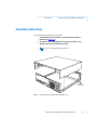
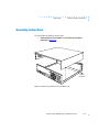
Attaching the Mounting Bracket to the Remote Annex 6300
Attach the rear mounting bracket to the Remote Annex 6300 as
follows:
1
Remove the mounting brackets and hardware kit from its package.
2
Remove two screws from the rear of the cover on each side of the
Remote Annex 6300, as shown in Figure 2-3. Save these screws; you
will need them later to install the rear mounting bracket.
3
Install rear mounting brackets to the device using the four screws
previously removed and the additional hardware supplied in the
hardware kit.
4
Tighten the screws to secure the bracket to the device.
Bracket Mounting
(2 Screws each side)
Bracket Assembly
(2 Screws, 2 Nuts, and
4 Washers each side)
Figure 2-3. Attaching the Mounting Bracket to the Remote Annex 6300
Remote Annex 6300 Hardware Installation Guide
2-5
Chapter 2
Installing the Remote Annex 6300
Attaching the Mounting Bracket and Device to the Rack
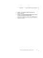
Attach the mounting bracket to the rack as follows:
Position the Remote Annex horizontally, facing forward in the rack.
2
Align the holes in the mounting bracket with the holes in the rack.
3
Insert the mounting screws and tighten the screws to attach the
Remote Annex 6300 to the rack (see Figure 2-4).
ISDN PRI
CONSOLE
10BASE5
10BASE2
115
1
10BASET
LINK
Figure 2-4. Attaching the Mounting Bracket and Device to the Rack
Connecting a LAN Using Ethernet
The Remote Annex 6300 supports three types of Ethernet connections:
Thin Ethernet, Thick Ethernet, or Twisted Pair (see Figure 2-5).
Each connection type requires a different connection procedure
described in the following sections. Connect only one type of Ethernet
cabling at one time.
Make sure the Remote Annex 6300 is powered off before
disconnecting or connecting the Ethernet cabling.
2-6
Remote Annex 6300 Hardware Installation Guide
Installing the Remote Annex 6300
ISDN PRI
CONSOLE
10BASE5
10BASE2
115
Chapter 2
10BASET
LINK
Thick Ethernet
(10Base5)
Twisted-Pair
Ethernet (10BaseT)
Thin Ethernet
(10Base2)
Figure 2-5. Remote Annex 6300 Ethernet Connections
The following subsections contain a description of how to connect
your Remote Annex 6300 to:
❑
Thin Ethernet (10Base2)
❑
Thick Ethernet (10Base5)
❑
Twisted Pair (10BaseT)
Connecting Thin Ethernet (10Base2) Cable
To connect Thin Ethernet (10Base2) or equivalent cable, you must use
a T-connector. The T-connector is installed in your Ethernet network
cable. Follow these steps to connect the Remote Annex 6300 to a Thin
Ethernet cable (see Figure 2-6):
Remote Annex 6300 Hardware Installation Guide
2-7
Chapter 2
Installing the Remote Annex 6300
1
Verify that both sides of the T-connector are connected to the Thin
Ethernet cable.
If the Remote Annex 6300 is the last device on the Thin Ethernet
segment, make sure that one side of the T-connector is connected
to the cable and the other side is connected to a network
terminator.
2
Plug the T-connector on the Thin Ethernet cable (RG-58 coaxial
cable) into the 10Base2 Ethernet connector located on the rear
panel of the Remote Annex 6300.
3
Twist the sleeve on the T-connector clockwise to lock the connection
in place.
Figure 2-6. Connecting Thin Ethernet Cable
2-8
Remote Annex 6300 Hardware Installation Guide
Chapter 2
Installing the Remote Annex 6300
Connecting Thick Ethernet (10Base5) Cable
To connect Thick Ethernet (10Base5) or equivalent transceiver cable,
you must have already installed a 10Base5 Ethernet network cable.
Follow these steps to connect the Remote Annex 6300 to a Thick
Ethernet cable (see Figure 2-7):
1
Make sure the transceiver cable is plugged into the Ethernet
network.
2
Push the slide mechanism on the Remote Annex 6300’s Thick
Ethernet connector to the right and plug in the transceiver cable.
3
Push the slide mechanism to the left to secure the connection.
Figure 2-7. Connecting Thick Ethernet Cable
Remote Annex 6300 Hardware Installation Guide
2-9
Chapter 2
Installing the Remote Annex 6300
Connecting Twisted Pair Ethernet (10BaseT) Cable
Follow the steps in this section to connect Twisted Pair (10BaseT)
Ethernet cable to the Remote Annex 6300 (see Figure 2-8):
1
Insert the connector located on the Twisted Pair Ethernet cable into
the 10BaseT connector on the rear panel of the Remote Annex 6300.
2
When the connector clicks into place, the connection is secure.
3
Verify that the Link Indicator is green.
The green link indicator LED next to the 10BaseT connector goes
on when power is applied and an active 10BaseT network
segment is plugged in.
Figure 2-8. Connecting Twisted Pair Ethernet Cable
2-10
Remote Annex 6300 Hardware Installation Guide
Chapter 2
Installing the Remote Annex 6300
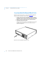
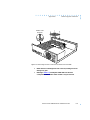
Connecting a Console Terminal
A console terminal is used to access the ROM Monitor and boot the
Remote Annex 6300 for the first time. Follow the steps in this section
to connect a console terminal to the console port located on the rear
panel of the Remote Annex 6300.
1
Connect the console terminal’s I/O connector to the cable (the
accessory kit includes a cable) using a DB-25 DTE drop adapter
(see Figure 2-9).
Figure 2-9. Connecting the Cable to the DB-25 DTE Drop Adapter
Remote Annex 6300 Hardware Installation Guide
2-11
Chapter 2
Installing the Remote Annex 6300
2
Plug the 8-pin connector into the console port located on the back
panel of the Remote Annex 6300 (Figure 2-10).
When the connector clicks into place, the connection is secure.
Appendix A describes the console port’s signal/pin allocation.
Figure 2-10. Connecting a Console Terminal
3
Turn on the console terminal and set the terminal to 9600 baud, eight
data bits, no parity, one stop bit, and XON/XOFF flow control.
The ROM Monitor assumes that this terminal is CRT-based and
displays the backspace (BS) character accordingly. See Chapter 3
for information on invoking the ROM monitor.
2-12
Remote Annex 6300 Hardware Installation Guide
Chapter 2
Installing the Remote Annex 6300
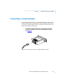
Connecting the PRI ISDN Interface
A PRI ISDN Interface is used to connect the Remote Annex 6300 to
an ISDN line. Follow the steps in this section to connect the ISDN line
to the PRI ISDN Interface port located on the rear panel of the Remote
Annex 6300.
1
Plug the RJ48C connector located on the PRI ISDN Interface Cable
into the PRI ISDN Interface port located on the rear panel of the
Remote Annex 6300 (see Figure 2-11).
When the connector clicks into place, the connection is secure.
Appendix A describes the PRI ISDN Interface port’s signal/pin
allocation.
Figure 2-11. Connecting the PRI ISDN Interface
Remote Annex 6300 Hardware Installation Guide
2-13
Chapter 2
Installing the Remote Annex 6300
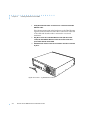
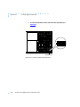
Powering Up and Testing the Remote Annex 6300
Power-up and test your Remote Annex 6300 as follows:
1
Verify the Remote Annex 6300’s operational power range.
Check that the power select switch is set to the 110V position
for operation in the 90 to 130 VAC range, or to the 220V
position for operation in the 180 to 260 VAC range (see
Figure 2-12).
ISDN PRI
CONSOLE
10BASE5
10BASE2
115
Power Select
Switch
10BASET
LINK
Figure 2-12. Verifying the Remote Annex 6300 Operational Power Range
Setting the power select switch incorrectly can damage the
Remote Annex 6300.
2
Apply power.
Connect the female end of the power cord to the AC line socket.
Connect the male end to an active AC line outlet (see
Figure 2-13). Turn the power switch on. The Power LED is
now active.
2-14
Remote Annex 6300 Hardware Installation Guide
Chapter 2
Installing the Remote Annex 6300
The Remote Annex 6300 now runs its ROM-resident power-up
diagnostics. The LEDs light and then turn off, except for some
status LEDs.
The ROM-resident, power-up diagnostics take 2 to
3 minutes to complete.
If the diagnostics complete successfully, the Remote Annex 6300
either enters Setup Mode and waits for configuration data to be
entered or boots its operational image from Flash.
Figure 2-13. Connecting the Power Cord
You can enter configuration information through a terminal
connected to the console port. The ROM Monitor prompt
(monitor::) appears on the terminal.
Remote Annex 6300 Hardware Installation Guide
2-15
Chapter 2
Installing the Remote Annex 6300
If the ATTN LED is ON or flashing, one of the following failures
has occurred (see Chapter 4 for more details):
❑
Remote Annex hardware failure; contact technical
support.
❑
Network or network interface failure; error message
displays on the console.
If a network or network interface failure occurs, typing
q accesses the ROM Monitor prompt. Check the network
connection and then see net on page 3-23.
3
Verify the Remote Annex 6300’s hardware configuration.
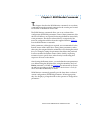
At the monitor prompt on the console, type config and press
Return . The screen display looks similar to this:
REVISION/CONFIGURATION INFORMATION
ROM Software Rev:
1002
Board ID: 63
Board Type: RA6300
CPU Type: 486DX2
Ethernet Address: 00-80-2D-02-CE-A9
Memory size: 8 Meg
EEPROM size: 65504
Flash size: 2 Meg
Flash ID: 8989
Available Interfaces (* = selected) ThickNet ThinNet *Twisted Pair
SLC Local DRAM Size: 4 Meg
TDM Interface: PRI T1 USA
Modem Country Code: 63
SLC SRAM Size: 128K
Revision: VERSION A MGR=1.117
Port #
Modem ID
Mod Status
1
2883
OK
2
2883
OK
3
2883
OK
4
2883
OK
5
2883
OK
6
7
8
9
10
11
12
2883 2883 2883 2883 2883 2883 2883
OK
OK
OK
OK
OK
OK
OK
Port #
Mod ID
Mod Status
13
2883
OK
14
2883
OK
15
2883
OK
16
2883
OK
17
2883
OK
18
19
20
21
22
23
24
2883 2883 2883 2883 2883 2883 2883
OK
OK
OK
OK
OK
OK
OK
This display is typical for T1 versions. For E1,
information, 32 ports will be shown. For versions
without modems, no port or modem information
will be shown.
2-16
Remote Annex 6300 Hardware Installation Guide
Chapter 2
4
Installing the Remote Annex 6300
Record the Remote Annex’s Ethernet address for future reference.
At the monitor prompt, type addr -d and press
display looks similar to this:
Return
. The screen
monitor:: addr -d
Ethernet address (hex): 00-80-2D-XX-XX-XX
Internet address: <uninitialized>
Subnet mask: 255.255.0.0
Broadcast address: 0.0.0.0
Preferred Load Host address: <any host>
Preferred Dump Host address: 0.0.0.0
Load/Dump Gateway address: 0.0.0.0
Type of IP packet encapsulation: <ethernet>
Load Broadcast: Y
Installing the Operational Software and Loading the
Image
Use this section if you have successfully connected the Remote Annex
6300 to your LAN.
This section describes:
❑
How to install the Remote Annex 6300’s operational software
and image on a device that resides on a network accessible
to the Remote Annex 6300.
❑
How to download the operational image from the device to
the Remote Annex 6300.
Remote Annex 6300 Hardware Installation Guide
2-17
Chapter 2
Installing the Remote Annex 6300
Installing to and Loading from a UNIX Host
This section describes how to install the Remote Annex 6300’s
operational software and image to a UNIX host (see the Annex
Administrator’s Guide for UNIX for more details).
1
Install the image on a UNIX host. The software installation notes
describe how to do this.
If you have a BOOTP server (see Chapter 3), boot
the Remote Annex 6300. Otherwise, continue to the
next step.
2
3
Execute the ROM Monitor addr command:
❑
Enter the Remote Annex 6300’s Internet address.
❑
Modify any other parameters that the Remote Annex
6300 may require for the initial boot, i.e., the preferred
load host’s Internet address and the subnet mask (see
addr on page 3-5).
Execute the boot command.
After successful execution of the boot command, the Remote
Annex 6300 is up and running (see boot on page 3-8).
Auto-initializing the Remote Annex 6300
The Remote Annex 6300 is distributed without an IP address or
preferred load host (UNIX/IP) defined in ROM. When the device is
booted, the Remote Annex 6300 attempts to auto-initialize itself using
BOOTP (bootstrap protocol) and RARP (Reverse Address Resolution
Protocol).
2-18
Remote Annex 6300 Hardware Installation Guide
Chapter 2
Installing the Remote Annex 6300
The Remote Annex 6300 supports the BOOTP and RARP protocols.
Use these protocols to obtain boot information from a UNIX host
without requiring any manual set-up on the Remote Annex 6300.
❑
BOOTP allows a diskless client to determine its IP address,
the IP address of the server, and the name of the file to be
loaded into memory.
❑
RARP maps a hardware address into an IP address.
The ROMs invoke this system of acquiring boot information when a
boot is initiated and the Remote Annex 6300 is not initialized. Under
this condition, the Remote Annex 6300 first tries to get boot
information via BOOTP or RARP.
If all requests fail, the Remote Annex 6300 will return to the ROM
monitor (if in Test mode) or continue the auto-initializing procedure
indefinately (if in Normal mode).
BOOTP
For a successful BOOTP retrieval, a bootpd must be running on a host
on the same network as the Remote Annex 6300 and must have the
appropriate information in the bootptab file. The Remote Annex
6300’s BOOTP implementation adheres to rfc951, rfc1048, and rfc1084.
A sample bootptab file entry used to initialize the Remote Annex 6300
named terminator looks like this:
remoteannexdefault:\
:sm=255.255.255.0:gw=132.245.22.66:\
:hn:vm=auto:to=-18000:
terminator:\
:ht=1:ha=00802d004879:ip=132.245.22.226:\
:tc=remoteannexdefault:
Remote Annex 6300 Hardware Installation Guide
2-19
Chapter 2
Installing the Remote Annex 6300
In the previous example:
❑
sm is the subnet mask.
❑
gw is the load/dump gateway address.
❑
vm is the Vendor Magic Cookie.
❑
ht is host type (1=Ethernet).
❑
ha is the Remote Annex 6300’s hardware address (Ethernet
Address).
❑
ip is the Remote Annex 6300’s Internet Address.
When the Remote Annex 6300 receives a BOOTP response with the sm,
gw, and ip set, it sets the respective parameters: subnet_mask,
load_dump_gateway, and inet_addr. The Vendor Magic Cookie
must be set to auto. This indicates that bootpd should respond to the
client (Remote Annex 6300 in this case) with whatever format the
client requests; the Remote Annex 6300 (client) always makes requests
in the decimal dot notation format (e.g., 99.130.83.99).
The bootpd adds the address of the host on which it is running as the
Server Address in the bootp response message. The ROMs use the
Server Address as the preferred load host and store it in the
pref_load_addr parameter.
The bootpd must be running on the Remote Annex’s preferred
load host.
RARP
If the Remote Annex 6300 does not receive a successful BOOTP
response, it uses RARP to get the boot information. For a successful
RARP retrieval, TCP/IP must be running on a host that is on the same
network as the Remote Annex 6300, and the host’s ARP table must
be initialized with the Remote Annex 6300’s Internet and Ethernet
addresses (see the arp man page, arp –s).
2-20
Remote Annex 6300 Hardware Installation Guide
Chapter 2
Installing the Remote Annex 6300
The only boot information that RARP provides is the Remote Annex
6300’s Internet address. The ROMs save this information in the
inet_addr parameter. The ROMs use default information for the
subnet mask and preferred load host. This means the ROMs will
broadcast their requests.
The host serving the Remote Annex 6300 its boot information must
be running on the same network as the Remote Annex 6300 because
the Remote Annex 6300 only broadcasts BOOTP and RARP queries.
If BOOTP and RARP fail, the Remote Annex 6300 transmits an IPX
Advertisement Request for Service and a MOP Multicast boot request.
If all requests fail, the Remote Annex 6300 returns to the ROM monitor
(if in Test mode) or continues the auto-initializing procedure
indefinately (if in normal mode).
Self-booting the Remote Annex 6300
The Remote Annex 6300 comes with Flash memory. Your device
already contains an operational image. You can check your Remote
Annex 6300’s configuration by entering the config command at the
Monitor prompt. The config command displays the current
configuration information and revision levels. If your device has Flash
ROM installed, the line FLASH PROM size: appears under the
REVISION/CONFIGURATION INFORMATION section.
Remote Annex 6300 Hardware Installation Guide
2-21
Chapter 2
Installing the Remote Annex 6300
To boot your Remote Annex 6300 from Flash ROM.
1
Enter the ROM Monitor prompt from the console.
2
Set the Internet address to a valid IP address and the subnet mask to
a valid mask using the addr command.
3
Set the interface sequence to self using the sequence command.
4
Boot the unit.
Invoking the Console Monitor
After the image boots, you can invoke a Console Monitor by pressing
Return on the console. At the Console Monitor prompt, entering help
or ? displays the available options:
2-22
❑
dump (from the Remote Annex to the host and reboots).
❑
help or ? (displays the available options).
❑
info (displays configuration information for the Remote
Annex).
❑
leds (displays the current front panel LED status).
❑
quit (exit the Console Monitor, e.g., quiet the console).
❑
reboot filename (reboots the Remote Annex).
❑
rom (returns the Remote Annex to the ROM Monitor).
❑
syslog (displays syslog messages).
Remote Annex 6300 Hardware Installation Guide
Chapter 3 ROM Monitor Commands
T
his chapter describes the ROM Monitor commands. Access these
commands through a terminal connected to the console port located
on the back of the Remote Annex 6300.
The ROM Monitor commands allow you to set a subset of the
configuration (EEPROM) parameters. Some of these parameters, like
the unit’s IP address, are required for booting the Remote Annex 6300;
some parameters, like the broadcast address, are required if the
network configuration differs from the supplied defaults. Table 3-1
lists the ROM Monitor commands.
Other parameters, although not required, are recommended for the
Remote Annex 6300’s initial boot. Setting these parameters, rather
than using the assigned defaults, minimizes errors during the initial
boot. For example, setting the parameter that defines the preferred
load host enables the Remote Annex 6300 to load by requesting
assistance from a specific host, rather than by broadcasting that
request to all hosts on the subnet.
After booting the Remote Annex, you can define the same parameters
you defined using the ROM monitor, using the na utility, the local
admin command, or SNMP. See Chapter 4 for information on Powerup and boot procedures; the Remoe Annex Administrator’s Guide for
UNIX describes the na utility in detail.
ROM Monitor commands generally provide data about a subset of
current configuration (EEPROM) parameters. When appropriate,
they also display a prompt that allows the operator to change those
parameters.
Remote Annex 6300 Hardware Installation Guide
3-1
Chapter 3
ROM Monitor Commands
Default or current values for parameters are displayed in brackets.
For example:
Enter broadcast address [132.245.6.255]:
At the prompt, enter a different value, or press
displayed value unchanged.
Return
to leave the
You can use unique abbreviations for all ROM Monitor commands
except erase. For example, enter boot as bo, and enter net as n. If you
enter an abbreviation that is not unique, an error message describing
the command as ambiguous is displayed on the console terminal.
Command Descriptions
Table 3-1 lists the ROM Monitor commands; the following subsections
describe them.
Table 3-1. ROM Monitor Commands
Command
Description
Use
addr [-d]
Displays and sets
EEPROM values
relevant to IP network
addressing, including
the unit’s IP address.
Changing IP
configuration
parameters.
boot [-v] [<file>]
Manually boots and
loads the unit’s
operating code.
Changing the address of
the boot image.
(continued on next page)
3-2
Remote Annex 6300 Hardware Installation Guide
Chapter 3
ROM Monitor Commands
Table 3-1. ROM Monitor Commands (continued)
Command
Description
Use
boot [-l] [<file>]
Erases the existing
Flash memory and
copies a new image to
Flash.
Upgrading or
replacing the Flash
image.
config
Displays the current
hardware
configuration and
revision levels.
Identifying your
hardware, memory,
and ROM versions.
console-baud
Changes the console
port’s baud rate.
Configuring the
console port for remote
maintenance.
erase
Erases non-volatile
memory.
Loading a new image
and need to erase the
old image.
help
Displays the list of
ROM Monitor
commands.
Referencing the ROM
monitor commands.
image [-d | <file>]
Displays and/or sets
the load image and
tftp load dump names.
Loading an image that
differs from the
default.
ipx [-d]
Displays and sets
EEPROM values
relevant to Novell/IPX
network addressing,
including the IPX
load/dump file server.
Changing Novell/IPX
configuration
parameters. This
command is not used
for this configuration
of the Remote Annex
6300.
Sets the LAT key.
Connecting to a DEC
VMS host.
(not supported in
this release)
lat_key [-d]
(continued on next page)
Remote Annex 6300 Hardware Installation Guide
3-3
Chapter 3
ROM Monitor Commands
Table 3-1. ROM Monitor Commands (continued)
Command
Description
Use
mop [-d]
Displays and sets
EEPROM values
relevant to VAX/VMS
network addressing,
including the MOP
load/dump address.
Loading software
from a DEC VMS
host. This
command is not
used for this
configuration of the
Remote Annex
6300.
net
Executes an Ethernet
transceiver loopback
test.
Checking your
Ethernet
connection.
option_key [-d]
Sets or displays the
option key.
Checking your
option key setting.
ping
Sends ICMP
ECHO_REQUEST
datagram to a host or
gateway.
Checking to see if a
host or gateway
can be reached.
ports [-d]
Shows the current
status of all ports.
Checking a port.
sequence [-d | <list>]
Displays and edits the
load/dump interface
list.
Checking or
changing the load/
dump interface list.
stats
Displays current
network statistics
gathered by the ROM.
Checking the
network resources.
(not supported in this
release)
3-4
Remote Annex 6300 Hardware Installation Guide
Chapter 3
ROM Monitor Commands
addr
The addr command displays and sets several Remote Annex 6300
operating parameters (EEPROM values) relevant to IP network
addressing:
❑
Internet address.
❑
Subnet mask.
❑
Broadcast address.
❑
Preferred Load Host address.
❑
Preferred Dump Host address.
❑
Load/Dump Gateway address.
❑
Type of IP Packet encapsulation.
❑
Load Broadcast
The addr -d command displays the unit’s ROM-resident Ethernet
address in hexadecimal notation. (For a description of Internet
addresses, see the Remote Annex Administrator’s Guide for UNIX.) The
command syntax is:
addr [–d]
If you enter the addr command without the –d argument, the console
prompts you for each Internet address. Enter Internet addresses using
the standard decimal dot (.) notation.
The addr –d command displays the Remote Annex 6300’s Ethernet
address, IP address, subnet mask, broadcast address, preferred load
host address, preferred dump host address, load/dump gateway
address, IP encapsulation type, and Load Broadcast. The addr -d
command cannot be used to make changes to any of the displayed
parameters.
Remote Annex 6300 Hardware Installation Guide
3-5
Chapter 3
ROM Monitor Commands
The addr command display looks like this:
monitor:: addr
Enter Internet address [<uninitialized>]:: 192.9.200.214
Internet address: 192.9.200.214
Enter Subnet mask [255.255.0.0]::
Enter Broadcast address [0.0.0.0]:: 192.9.200.0
Broadcast address: 192.9.200.0
Enter Preferred Load Host address [<any host>]::
192.9.200.88
Preferred Load Host address: 192.9.200.88
Enter Preferred Dump Host address [0.0.0.0]:: 192.9.200.88
Preferred Dump Host address: 192.9.200.88
Enter Load/Dump Gateway address [<uninitialized>]::
192.9.200.10
Load/Dump Gateway address: 192.9.200.88
Select type of IP packet encapsulation (ieee802/ethernet)
[<ethernet>]::
Load Broadcast Y/N [Y]::
The addr -d command display looks like this:
monitor:: addr -d
Ethernet address (hex): 00-80-2D-00-18-B6
Internet address: 192.9.200.214
Subnet mask: 255.255.0.0
Broadcast address: 192.9.200.0
Preferred Load Host address: 192.9.200.88
Preferred Dump Host address: 192.9.200.88
Load/Dump Gateway address: 192.9.200.10
Type of IP packet encapsulation: <ethernet>
Load Broadcast: Y
3-6
Remote Annex 6300 Hardware Installation Guide
Chapter 3
ROM Monitor Commands
The Remote Annex 6300 must have an Internet (IP) address in its
memory before it can load its operational image across the Ethernet
via the IP protocol. Therefore, you must enter the IP address before
booting the Remote Annex 6300 from a UNIX load host. If you do not
define a subnet mask, the Remote Annex 6300 uses the generic mask
for the specified IP address.
The Remote Annex 6300 tries to boot from a preferred UNIX load
host. If you do not define a preferred load host, the Remote Annex
6300 broadcasts its load request and loads software from the first host
that responds.
If the part of the IP address containing the network address differs
from that of the preferred load or dump host, the host must be reached
through a gateway. The addr command prompts you for this
gateway’s IP address.
The Remote Annex 6300 uses the broadcast address parameter when
loading a file. If this parameter contains a specific address (for
example, 132.245.6.255), the Remote Annex 6300 uses only that
address for broadcast. If the value is all zeroes (0.0.0.0), the ROM
Monitor tries various combinations of broadcast addresses and
subnet or network broadcasts. The Remote Annex 6300 broadcasts its
request three times for each possible combination of broadcast
addresses.
You can specify the IP encapsulation type as either ethernet for
Ethernet, or ieee802 for IEEE 802.2/802.3. The default IP
encapsulation is ethernet. Many systems have hardware Ethernet
interfaces that are IEEE 802.3 compliant, but very few actually do
802.3 IP packet encapsulation.
Do not change this parameter unless you know absolutely that
your Ethernet does 802.2/802.3 IP packet encapsulation. An
incorrect IP encapsulation type prevents your Remote Annex
from booting.
Remote Annex 6300 Hardware Installation Guide
3-7
Chapter 3
ROM Monitor Commands
boot
The boot command requests the loading of appropriate Remote
Annex 6300 operating software from a cooperating host. The
command syntax is:
boot [–lv | filename]
Typing the letter q or
Control
-C interrupts the boot.
If you try to boot with a non-existent image file name, the
Annex will hang as it searches for the image. You must press
the Reset button to recover.
A successful boot disables the ROM Monitor.
The boot command accepts a file name for the Remote Annex 6300’s
image. If the file name is not specified, boot displays the default file
name and prompts for one. If you do not provide a file name, or have
not defined one for the Remote Annex 6300, boot requests the default
oper.63.enet file. Optionally, you can enter a file name using the
image command.
The Remote Annex 6300 boots from the defined preferred load host.
If the preferred load host is not defined or does not respond, the
Remote Annex 6300 broadcasts on the Ethernet and loads from the
first host that responds.
To initiate loading, the Remote Annex 6300 sends a load request
message to the selected host. After receiving a response, the Remote
Annex 6300 loads its operational code to RAM. When loading is
complete, it transfers control to the newly-loaded program. The
Remote Annex 6300 displays a symbol on the console for each data
block received during the boot.
3-8
Remote Annex 6300 Hardware Installation Guide
Chapter 3
ROM Monitor Commands
When the Remote Annex 6300 begins to boot, it displays the load
server host’s Internet address. If the unit does not boot successfully
after several attempts, it displays a boot attempt failed message; if the
unit has opened the boot file and an error occurs during the boot
process, it displays a boot error report on the console and returns to
the ROM Monitor. The boot error report can help determine the cause
of the boot failure (see Boot Error Report on page 4-11).
During a boot, the console may display four possible status symbols:
“.” indicates received data blocks, “?” indicates unanswered requests,
“*” indicates transmission errors, and “! ~XXXX~” is a status word
from the Ethernet chip on the Annex indicating a gross problem with
the Ethernet connection (if this symbol appears in your boot
command display, contact technical support).
The status word “! ~XXXX~”, where XXXX are four hexadecimal
digits, decodes as follows:
8000 = Command complete
4000 = Chip is busy
2000 = Command completed without error
1000 = Command aborted issuance of an ABORT command
800 = Late collision detected
400 = Carrier lost
200 = CTS lost
100 = DMA underrun
80 = Transmission deferred because link was busy
40 = Collision detected during interframe spacing (SQE/Heartbeat
detected)
20 = Excessive collisions
10 = Reserved
The lowest nibble (bits 3 to 0) are a count of collisions during this
transmission. For example:
~8802~ = Complete, Late collision, 2 collisions
~8841~ = Complete, Late Collision, SQE detected, 1 collision
Remote Annex 6300 Hardware Installation Guide
3-9
Chapter 3
ROM Monitor Commands
The boot command display (using bfs) looks like this:
monitor:: boot
Enter boot file name[(ip) “oper.63.enet”,\
(mop) “OPER_63_ENET.SYS”]::
Requesting default boot file “OPER_63_ENET.SYS” for MOP/VMS\
loads and “oper.63.enet” for all other protocols.
Unanswered requests shown as ‘?’,transmission errors as ‘*’.
Requesting boot from 192.9.200.88 via Ethernet...
Booting BFS file using open delay of 8
Booting BFS file from 192.9.200.88
Header received OK. Received data blocks shown as ‘.’.
. . . . . . . . . . . . . . . . . . . . . . . . . . . . . .. .
. . . . . . . . . . . . . . . . . . . . . . . . . . . . . . .
.. . . . . . . . . . . ? . . . . . . . . . . . . . . . . . . .
. . . . . . . . . . . . . . . . . . . . . . . . . . . . . . .
. . . . . . . . . . . . . . . . . . . . . . . . . . . . * . .
. . . . . . . . . . . . . . . . . . . . . . . . . . . . . . .
. . . . . . . . . . . . . ? . . . . . . . . . . . . . . . . .
. . . . . . . . EOF
.
.
.
*
.
.
.
The next example shows a boot using tftp. The Remote Annex always
tries to open a file using bfs first. If unsuccessful, the Remote Annex
uses tftp to open the file.
monitor:: boot
Enter boot file name [(ip) “oper.63.enet”, \
(mop) “OPER_63_ENET.SYS”]::
Requesting default boot file “OPER_63_ENET.SYS” for MOP/VMS\
loads and “oper.63.enet” for all other protocols.
Unanswered requests shown as ‘?’,transmission errors as ‘*’.
Requesting boot from 192.9.200.88 via Ethernet...
Booting BFS file using open delay of 8
?
Booting TFTP file using open delay of 8
Booting TFTP file from 192.9.200.88
Header received OK. Received data blocks shown as ’.’.
.. . . . . . . . . . . . . . . . . . . . . . . . . . . . . .
. . . . .. . . . . . . . . . . ? . . . . . . . . . . . . . .
. . . . . . . . . . . . . . . . . . . . . . . . . . . . . . .
. . . . * . . . . . . . . . . . . . . . . . . . . . . . . . .
. * . . . . . . . . . . . . . . . . . . . ? . . . . . . . . .
. . . . . . . . . . . . . . . . EOF
3-10
Remote Annex 6300 Hardware Installation Guide
.
.
.
.
.
Chapter 3
ROM Monitor Commands
The boot –l command downloads and saves the operational image to
non-volatile memory, erases the existing Flash memory, copies the
new image from non-volatile memory to Flash memory, and then
executes the image.
After executing a boot –l, the ls command may not show the
newly-loaded image.
The boot –l command display looks like this:
monitor:: boot –l
Enter boot file name [(ip) “oper.63.enet”, \
(mop) “OPER_63_ENET.SYS”]::
Requesting default boot file “OPER_63_ENET.SYS” for \
MOP/VMS loads and “oper.63.enet” for all other protocols.\
Unanswered requests shown as ‘?’,transmission errors as‘*’.
Requesting boot from 192.9.200.88 via Ethernet...
Booting BFS file using open delay of 8
Booting from 192.9.200.88
Header received OK. Received data blocks shown as ‘.’.
. . . . . . . . . . . . . . . . . . . . . . . . . . . . . ..
. . . . . . . . . . . . . . . . . . . . . . . . . . . . . ..
. . . . . . . . . . . . . . . . . . . . . . . . . . . . .
. . . . . . . . . . . . . . . . . . . .EOF
Saving image into storage device ...
Erasing device
|----------------------------|
..............................
Erase completed
Storing image .............
Storage completed
Beginning execution of image...
Annex Command Line Interpreter * Copyright 1991, 1995\
Xylogics, Inc.
Remote Annex 6300 Hardware Installation Guide
3-11
Chapter 3
ROM Monitor Commands
Use boot –l only when reloading your Flash memory.
Typically, you reload your Flash memory when you are
upgrading to a new version of software.
Make sure that you have a properly configured load host
available or you will erase erase your image from Flash and
will not be able to load a new one.
The boot –v command displays the boot in verbose mode. This output
includes the turnaround time in milliseconds for each request. This
value equals the time lapse between sending the request and receiving
the proper reply from the host.
When the boot is complete, verbose output includes a display of
network statistics:
monitor:: boot –v
Enter boot file name [(ip) “oper.63.enet”, \
(mop) “OPER_63_ENET.SYS”]::
Requesting default boot file “OPER_63_ENET.SYS” for MOP/VMS\
loads and “oper.63.enet” for all other protocols.
Unanswered requests shown as ‘?’, transmission errors as ‘*’.
Requesting boot from 192.9.200.88 via Ethernet...
Booting from 192.9.200.88 (42 msec)
Header received OK. Received data blocks shown as msec
turnaround time.
4 4 6 4 4 4 4 4 4 4 4 4 4 4 4 4 4 4 4 4 4 4 4 4 4 4 4 6 4 4 4 4 4
4 4 4 4 4 4 4 4 4 4 4 4 4 4 4 4 6 4 4 4 4 4 4 4 4 4 4 4 4 4 5 4 4
4 4 4 4 4 6 4 4 4 4 4 4 4 4 4 4 4 4 4 4 4 4 4 4 4 4 4 4 4 4 6 4 4
4 4 4 4 4 4 4 4 4 4 4 4 4 4 4 4 4 4 4 4 4 4 6 4 24 4 4 6 4 10 4 6
73 4 4 5 4 4 4 4 4 9 4 4 11 4 4 4 4 4 4 4 4 4 4 4 4 4 3 4 4 4 4 4
4 4 6 4 4 4 4 4 4 4 4 4 4 4 4 4 4 4 4 4 4 4 4 4 4 4 11 6 4 4 4 4
4 4 4 4 4 4 4 4 4 4 4 4 4 4 4 4 6 4 4 4 4 4 4 4 4 4 4 4 4 4 4 4 4
4 4 4 4 4 6 4 4 4 4 4 4 4 4 4 4 4 4 4 4 4 4 4 4 4 4 4 4 4 4 6 4 4
4 4 4 4 4 4 4 4 4 4 4 4 4 4 4 4 4 4 4 6 EOF
Ethernet Statistics
Frames Received:
CRC Errors:
Alignment Errors:
Resource Drops:
Bus Wait Drops:
Bad Types/Lengths:
3-12
Remote Annex 6300 Hardware Installation Guide
1031
0
0
9
0
0
Frames Sent:
Carrier Sense Losses:
Clear to Send Losses:
Collisions Detected:
Excessive Collision Losses:
1031
0
0
9
0
Chapter 3
ROM Monitor Commands
config
The config command displays the current configuration information
and revision levels for the Remote Annex 6300. The config command
displays revision information, the amount of memory installed, T1 or
E1 configuration information, and a description of the number and
type of modems installed. The command syntax is:
config
The config command display for a Remote Annex 6300 with 24
modems (T1) looks similar to this:
REVISION/CONFIGURATION INFORMATION
ROM Software Rev: 1002
Board ID: 63
Board Type: RA6300
CPU Type: 486DX2
Ethernet Address: 00-80-2D-02-CE-A9
Memory size: 8 Meg
EEPROM size: 65504
Flash size: 2 Meg
Flash ID: 8989
Available Interfaces ( *= selected) ThickNet ThinNet *Twisted Pair
SLC Local DRAM Size: 4 Meg
TDM Interface: PRI T1 USA
Modem Country Code : 63
SLC SRAM Size: 128 K
Revision: VERSION A MGR=1.117
Port #
Modem ID
Mod Status
1
2
3
2883 2883 2883
OK
OK
OK
4
5
6
7
8
9
10
11
12
2883 2883 2883 2883 2883 2883 2883 2883 2883
OK
OK
OK
OK
OK
OK
OK
OK
OK
Port #
Modem ID
Mod Status
13
14
15
2883 2883 2883
OK
OK
OK
16
17
18
19
20
21
22
23
24
2883 2883 2883 2883 2883 2883 2883 2883 2883
OK
OK
OK
OK
OK
OK
OK
OK
OK
This display is typical for T1 versions. For E1 versions,
information on 32 ports will be shown. For modem-less
versions, no port or modem information will be shown.
Remote Annex 6300 Hardware Installation Guide
3-13
Chapter 3
ROM Monitor Commands
console-baud
The console-baud command changes the console port’s baud rate.
Thus, the console port can interface with any modem to which it is
connected. When the baud rate is entered as auto, the Remote Annex
6300 detects the baud rate of the incoming line and adjusts its baud
rate accordingly. This command provides support for remote
troubleshooting. The command syntax is:
console-baud
The command display looks like this:
monitor:: console-baud
Remote Diagnostic Test Mode
In order to use the remote diagnostic functionality, you
must first connect a modem to the console port of the
Annex. The modem should be configured such that DTR is
forced on, carrier detect and DSR are set normal, and
auto-answer is enabled. Once this is done, contact your
service representative for remote diagnostic maintenance.
To enter “Autobaud Mode”, please type “Auto”. To
“manually” configure the Annex console port, please type
in the desired baud rate. To return to the “monitor::”
prompt strike the “carriage return <CR>” key.
[Baudrate Range: 50–9600 BAUD]
Select Baudrate []:
This command has no effect on the port’s baud rate after the
Remote Annex 6300 is booted.
3-14
Remote Annex 6300 Hardware Installation Guide
Chapter 3
ROM Monitor Commands
To provide remote access to the Remote Annex 6300 ROMs:
1
2
3
From a site local to the Remote Annex 6300:
❑
Put the Remote Annex in test mode so the monitor
prompt appears on the console.
❑
Set the modem to auto-answer mode.
From the Remote Annex 6300 console port:
❑
At the monitor prompt, enter console-baud.
❑
At the Select Baud Rate prompt, enter the appropriate
baud rate or auto.
❑
Connect the modem to the Remote Annex’s console port.
From the remote site:
❑
Dial into the modem connected to the Remote Annex.
❑
Press the
Return
key until the monitor prompt appears.
Remote Annex 6300 Hardware Installation Guide
3-15
Chapter 3
ROM Monitor Commands
erase
The erase command erases the contents of non-volatile memory,
including the Remote Annex 6300’s Internet address. This command
also restores the parameters to their factory defaults. The syntax is:
erase
If the self-boot option is installed, the erase command prompts for
the non-volatile memory to erase: EEPROM or FLASH. Entering 1 at
the prompt causes the Remote Annex to erase the EEPROM memory
(configuration information); entering 2 at the prompt causes the
Remote Annex to erase the Flash memory (self-boot image).
The erase command does not erase the Ethernet address.
Since the erase command erases the IP address, you must use
the addr command to re-enter the Remote Annex’s IP address
before reloading any software.
The erase command display looks like this:
monitor:: erase
1) EEPROM (i.e. Configuration information)
2) FLASH (i.e. Self boot image)
Enter 1 or 2:: 1
Erase all non-volatile EEPROM memory? (y/n) [n]:: y
Erasing 65504 bytes of non-volatile memory. Please
wait...
16K->|Data 0x0
...............................................
Initialized checksum record installed
WARNING
.
.
.
3-16
Remote Annex 6300 Hardware Installation Guide
Chapter 3
ROM Monitor Commands
If the self-boot option is not used, the command display looks like this:
monitor:: erase
Erase all non-volatile EEPROM memory? (y/n) [n]:: y
Erasing 65504 bytes of non-volatile memory. Please
wait...
16K->|Data 0x0
.................................................
Initialized checksum record installed
Erasing 65504 bytes of non-volatile EEPROM memory
WARNING
Remote Annex 6300 Hardware Installation Guide
3-17
Chapter 3
ROM Monitor Commands
help
Entering help, or ?, displays brief descriptions of the Remote Annex
6300 ROM Monitor commands.
3-18
Remote Annex 6300 Hardware Installation Guide
Chapter 3
ROM Monitor Commands
image
The image command sets and displays the name of the image file
containing the Remote Annex 6300’s software. The syntax is:
image [–d | filename]
The filename argument permits up to 100 characters. To return the
image name to its default, enter a pair of double-quote characters ("").
The default image name is oper.63.enet. The image command display
looks like this:
monitor:: image
Enter Image name: [(ip)"oper.63.enet", \
(mop) "OPER_63_ENET.SYS"]::
Enter TFTP Load Directory [""]::
Enter TFTP Dump path/filename ["dump.192.9.200.88"]::
The image –d command display looks like this:
monitor:: image –d
Image name:Default (ip): "oper.63.enet"
Default (mop):"OPER_63_ENET.SYS"
TFTP Load Directory: ""
TFTP Dump path/filename: "dump.192.9.200.88"
SELF image name: "oper.63.enet"
The SELF image name appears only if the self-boot image is
loaded.
If the image file name contains more than 16 characters, it is
truncated when MOP is attempted.
Remote Annex 6300 Hardware Installation Guide
3-19
Chapter 3
ROM Monitor Commands
ipx
This release does not support this command.
The ipx command sets several parameters associated with IPX
booting and dumping. This is useful when loading the Remote Annex
6300’s operational image from a Novell file server. The syntax is:
ipx [–d]
The ipx command display looks like this:
monitor:: ipx
Enter IPX file server name [<uninitialized>]:: mars
Enter Frame type, 0=802.3 1=Ethernet II 2=802.2 3=SNAP\
[802.3]::
Enter IPX dump user name [<uninitialized>]:: susans
Enter IPX dump password [<uninitialized>]:: ******
Verify IPX dump password []:: ******
Enter IPX dump path [<uninitialized>]:: SYS:\user\susans\
The ipx –d command displays the current settings for all of the entries.
The command display looks like this:
monitor:: ipx –d
IPX preferred load file server: “MARS”
IPX frame type: "802.3"
IPX dump user name: “SUSANS”
IPX dump password: <SET>
IPX dump path name: “SYS:\user\susans\”
3-20
Remote Annex 6300 Hardware Installation Guide
Chapter 3
ROM Monitor Commands
lat_key
The lat_key command allows you to set the LAT key from the ROM
monitor.
The lat_key is optional and may be purchased separately.
The command syntax is:
lat_key [–d]
The lat_key command display looks like this:
monitor:: lat_key
Enter LAT KEY [<uninitialized>]::
The lat_key –d command displays the current LAT key setting:
monitor:: lat_key –d
Enter LAT KEY [<uninitialized>]::
Remote Annex 6300 Hardware Installation Guide
3-21
Chapter 3
ROM Monitor Commands
mop
This release does not support this command.
The mop command sets the MOP load/dump address. This is useful
when the loading the Remote Annex 6300’s operational image from
a VAX VMS load host. The command syntax is:
mop [–d]
The mop command display looks like this:
monitor:: mop
Enter preferred MOP load/dump address [<uninitialized>]::
Load Broadcast Y/N [Y]::
The mop –d command displays the current MOP settings:
monitor:: mop –d
MOP preferred load/dump address: <uninitialized>
Load Broadcast: Y
3-22
Remote Annex 6300 Hardware Installation Guide
Chapter 3
ROM Monitor Commands
net
The net command executes an Ethernet transceiver loopback test on
the local area network. The command syntax is:
net
The net command display looks like this:
monitor:: net
Network test – PASSED
This transceiver loopback test sends out a short test packet from the
Remote Annex 6300 through the transceiver to test the integrity of the
network. The test can be executed either by attaching the Remote
Annex 6300 to the Ethernet or by attaching an Ethernet loopback
connector to the network port.
For the 10Base2 and 10Base5 network interfaces, the preferred method
for running an Ethernet transceiver loopback test is to attach the
loopback connector to the network port because short test packets can
interfere with normal network traffic. The accessory kit supplies
Ethernet loopback connectors for these interfaces.
The 10BaseT network interface does not require a loopback connector
because it provides a Link Integrity LED next to the connector. This
LED verifies that the receive circuit to the wiring concentrator is
operating correctly. If this LED is not lit, link LED impulses are not
present on the receive line due to a disconnected cable or some other
link failure.
The Ethernet transceiver loopback test causes the Net LED to turn off.
If the unit passes this test, the Net LED turns on and the console
displays PASSED. If the Remote Annex 6300 fails, the Net LED
remains off, and the console displays an error message.
Remote Annex 6300 Hardware Installation Guide
3-23
Chapter 3
ROM Monitor Commands
Failing this test indicates that either the Remote Annex 6300, its
transceiver cable, its transceiver, or the Ethernet, is bad. Isolate the
failure by using this test and the Ethernet loopback connector. Any
of the following conditions can cause these test failures:
1
The Remote Annex 6300 has faulty Ethernet port electronics.
To test for this condition, connect the Ethernet loopback
connector directly into the network connector. Run the net test
again. If errors still occur or the +12-volt LED on the 10Base5’s
loopback connector fails to light, the problem is with the
Remote Annex 6300; call technical support.
2
The Remote Annex 6300 transceiver cable is defective or
disconnected (this problem occurs only with the 10Base5 interface).
To test for this condition, connect the 10Base5’s loopback
connector to the transceiver end of the transceiver cable (while
the cable is connected to the Ethernet port) and run the net
test. If errors did not occur during the first test run, but do
occur during this test, the cable is faulty and should be
replaced.
3
The transceiver at the end of the transceiver cable is defective or
improperly connected to the Ethernet.
If the cable is free of faults (tested as described above) and
other devices on the Ethernet are not experiencing difficulties,
the problem is in the transceiver. If you have already ruled out
the transceiver, contact technical support.
4
The Ethernet cable is shorted or improperly terminated.
Other devices on the network should show evidence of
problems.
3-24
Remote Annex 6300 Hardware Installation Guide
Chapter 3
ROM Monitor Commands
option_key
The option_key command loads an option key from the ROM
monitor. The command syntax is:
option_key [–d]
The option_key command display looks like this:
monitor:: option_key
Enter option_key [<uninitialized>]::
The option_key –d command displays the current settings:
monitor:: option_key –d
option_key: <uninitialized>
Remote Annex 6300 Hardware Installation Guide
3-25
Chapter 3
ROM Monitor Commands
ping
The ping command sends an Internet Control Message Protocol
(ICMP) mandatory ECHO_REQUEST datagram to elicit an ICMP
ECHO_RESPONSE from a host or gateway. ECHO_REQUEST
datagrams (pings) have an IP and ICMP header, followed by a
structured time value and an arbitrary number of pad bytes that fill
out the packet. The syntax for this command is:
ping host_ip_address [data_size] [npackets]
❑
The host_ip_address entry is the Internet address of the host
or gateway from which you wish to elicit a response.
❑
The optional data_size entry is the number of bytes sent in a
datagram packet. The default value is 64 and the maximum
value is 1024.
❑
The optional npackets entry is the number of packets to
transmit. If you specify npackets, then you must also specify
a data_size.
The ping command display looks something like this:
monitor:: ping 132.245.33.69
PING 132.245.33.69: 64 data bytes
If you enter the ping command without specifying an IP address, the
display looks like this:
monitor:: ping
IP address required, ie: ping 132.245.33.69\
[data bytes] [npackets]
To exit out of ping either wait for npackets to be transmitted or, at any
point, type q. The ping statistics display upon exit.
3-26
Remote Annex 6300 Hardware Installation Guide
Chapter 3
ROM Monitor Commands
ports
The ports command tests the PRI interface port. The syntax is:
ports
To test the PRI port, the interface must be connected to a loopback
plug. No external clocking is required.
When invoked, the command displays a menu of options. The
following is a sample screen display for a T1 or E1 version of the
Remote Annex 6300.
monitor:: ports
Some Important Notes:
- These tests require the PRI port to have a loopback
plug installed.
- An even number of ports must be selected for the Modem
Ports test because pairs of modems are connected
together and data is looped back between them.
1) Digital Ports
2) Modem Ports
Selection (Return to exit)::
The following is a sample screen display for a modem-less version of
the Remote Annex 6300.
monitor:: ports
Some Important Notes:
- These tests require the PRI port to have a loopback
plug installed.
Ports with faulty Data Lines:
Enter port number or range of ports to test
(Return to exit)::
Remote Annex 6300 Hardware Installation Guide
3-27
Chapter 3
ROM Monitor Commands
sequence
The sequence command edits the load/dump interface list. This list
determines the order of the network interfaces the Remote Annex
6300 will use for loading and dumping. The default, net, uses the LAN
interface. If the Remote Annex 6300 fails to boot using the first
interface, it will try the next interface. The command syntax is:
sequence [–d] | [interface[,interface]. . .]
Specify the LAN interface by selecting net. Separate each interface
with a comma or a space. Enter the interface list as an argument to
the command, otherwise the console displays a list of available
interfaces and prompts for a new list.
In the following example, interfaces are assigned to the load/dump
sequence list.
monitor:: sequence
Enter a list of 1 to 4 interfaces to attempt to use for
downloading code or upline dumping. Enter them in the order
they should be tried, separated by commas or spaces.
Possible interfaces are:
Ethernet:net
SELF:
self
Enter interface sequence [net]:: self, net
Interface sequence: self,net
The sequence –d command displays the current load/dump interface
list. You cannot specify both the –d argument and the interface list
with the same command. The command display looks like this:
monitor:: sequence –d
Interface sequence: self,net
3-28
Remote Annex 6300 Hardware Installation Guide
Chapter 3
ROM Monitor Commands
stats
The stats command displays current network statistics gathered by
the ROM. Use stats along with the boot command to help isolate
problems. Table 3-2 describes the network statistics displayed by the
stats command. The syntax is:
stats
The stats command display looks like this:
monitor:: stats
Ethernet Statistics
Frames Received:
398
CRC Errors:
0
Alignment Errors
0
Resource Drops:
0
Bus Wait Drops:
0
Bad Types/Lengths:
0
Frames Sent:
Carrier Sense Losses:
Clear to Send Losses:
Collisions Detected:
Excessive Collision Losses:
3
0
0
0
0
Table 3-2. Network Statistics
Statistic
Description
Frames Received
The number of frames received.
CRC Errors
The number of CRC checksum errors detected.
Alignment Errors
The number of frames received misaligned with a
CRC error.
Resource Drops
The number of packets dropped because the ROM
code could not buffer them quickly enough. The
ROM code cannot always handle back-to-back
incoming packets. The Remote Annex accepts the
first response it receives and drops all others.
Dropped packets are normal.
(continued on next page)
Remote Annex 6300 Hardware Installation Guide
3-29
Chapter 3
ROM Monitor Commands
Table 3-2. Network Statistics (continued)
3-30
Statistic
Description
Bus Wait Drops
The number of packets dropped due to waiting too
long for a bus to become available.
Bad Types/
Lengths
The number of unknown packet types if Ethernet
IP encapsulation is being used. The number of
packets with illegal lengths if IEEE 802.2/802.3 IP
encapsulation is being used.
Frames Sent
The number of frames sent.
Carrier Sense
Losses
The number of times packets could not be
transmitted because the Remote Annex 6300 lost
the Carrier Sense signal – usually the result of
excessive traffic on the Ethernet.
Clear to Send
Losses
The number of times packets could not be
transmitted because the Remote Annex 6300 lost
the Clear to Send signal – usually the result of
excessive traffic.
Collisions Detected
The number of times the Remote Annex 6300 had
to retry transmissions automatically – usually the
result of normal Ethernet traffic. These retries do
not cause the boot command to display ‘‘*.”
Excessive Collision
Losses
The number of times the Remote Annex 6300
could not transmit packets because there were too
many collisions – usually the result of excessive
traffic on the Ethernet. The boot command
displays these retries as “*.”
Remote Annex 6300 Hardware Installation Guide
Chapter 4
Troubleshooting Procedures
T
he Remote Annex 6300’s front panel contains a number of LEDs
that provide information about normal operations and about
problems that occur. Use these LEDs and the ROM Monitor
commands to diagnose problems. Figure 4-1 illustrates the Remote
Annex 6300’s front panel LEDs.
Modem Port
Status LEDs
Modem Config
Status LEDs
Remote Annex 6300
Modem Config
Status
13-16 9-12
Modem Status
Bay Networks
32
31
30
29
28
27
26
25
24
23
22
21
20
19
18
17
16
15
14
13
5-8
1-4
29-32 25-28 21-24 17-20
12
11
10
9
8
7
6
5
4
3
2
1
CD
Tx/Rx
Xylogics, a Bay Networks Company
Network/Status
Ararms
Test Sync Los
PRI Channel Status
32
31
30
29
28
27
26
25
24
23
22
21
20
19
18
17
16
15
14
13
12
11
10
9
8
7
6
5
4
3
PRI Channel
Status LEDs
2
1
Red
Yel
Stat
Blu
Attn
Traf
Setup Power
Reset
Network
Status Alarms
Figure 4-1. Remote Annex 6300 Front Panel Alarms and LEDs
Refer to Table 4-1 for a description of the LEDs located on the front of
the Remote Annex 6300.
Remote Annex 6300 Hardware Installation Guide
4-1
Chapter 4
Troubleshooting Procedures
Table 4-1. Remote Annex 6300 Front Panel LEDs
LED(s)
Description
Modem
Status
The Remote Annex 6300 has two status LEDs for each
modem port (up to 32):
CD - Data Carrier Detect is a green LED and is on when
the carrier has been detected on the telephone line on the
corresponding modem.
TX/RX - TX/RX is a green LED that flashes to indicate
that the corresponding modem is transmitting or receiving
data.
Modem
Config
Status
These LEDs indicate the number of modems installed. An
LED is green if all the modems in its group are good. An
LED is amber if one modem in its group is bad.
PRI Channel
Status
These green LEDS indicate B channel allocation. There are
32 PRI Channel Status LEDs on the front of the Remote
Annex 6300. For T1, 23 are used to indicate B channel
allocation. For E1, 30 are used for B channel allocation.
Network/
Status
Alarms
RED - RED alarm LED is ON during a locally detected
carrier failure. During the RED alarm condition, a
YELLOW alarm is transmitted across the telephone
network.
YEL - YELLOW alarm LED is ON when receiving a
YELLOW alarm condition from the telephone network.
BLU - BLUE alarm LED is ON when receiving an unframed,
all-ones Alarm Indication Signal (AIS) from the network. This
condition exists upon a loss of originating signal, or when any
action is taken that would cause a signal disruption.
(continued on next page)
4-2
Remote Annex 6300 Hardware Installation Guide
Chapter 4
Troubleshooting Procedures
Table 4-1. Remote Annex 6300 Front Panel LEDs (continued)
LED(s)
Description
Network/
Status
Alarms
(continued)
TEST - RED network TEST LED is ON when the ISDN
Network Interface is looped back. Loopback tests are
activated either locally by the user or by the telephone
company.
SYNC - GREEN SYNC LED is ON when the PRI interface
is properly synchronized with the received network signal
and is receiving proper framing information.
LOS - RED LOS LED is ON when the PRI inteface is
detecting no signal (pulses) on the network interface
receiver. When a LOS condition exists, the PRI interface
transmits unframed all one (AIS) to the network.
ATTN - The ATTN (Attention) LED is amber and ON
when the Remote Annex requires operator attention. The
LED flashes when there is a problem.
STAT - The STAT (Status) LED is green and ON after the
Remote Annex passes the core power-up diagnostics. The
LED flashes after resetting the Remote Annex.
TRAF - The TRAF (Traffic) LED is green and flashing
when the Remote Annex 6300 successfully transmits or
receives data from the LAN.
SETUP - The SETUP LED is green when the Reset button
is pressed ON (Setup mode) and flashing when the
Reset button is pressed ON for 3 seconds (Reset mode).
Power
This LED is ON when the Remote Annex 6300 is
connected to an AC power source.
If you are using an external CSU, some of the Network/Status
alarm LEDs may not give true readings. In this case, defer to
the status and alarm conditions indicated on the external CSU.
Remote Annex 6300 Hardware Installation Guide
4-3
Chapter 4
Troubleshooting Procedures
In addition to the front panel LEDs, the Remote Annex 6300 contains
a Link LED on the rear panel. The Link LED is green when an active
10BaseT segment is attached.
During power-up and booting, it is more difficult to diagnose
problems because they can originate in the Remote Annex 6300, the
transceiver, the Ethernet, or the load server host. However, the LEDs
provide both a progress report and an error display to assist you in
troubleshooting.
If an error occurs, save the status of these LEDs. Technical
support personnel can use this information to
diagnose problems.
This chapter describes power-up and booting, troubleshooting
during booting, and the file created from a Remote Annex 6300 dump.
Power-up and Boot Procedures
The Remote Annex 6300 has two modes of operation: normal and
setup. Normal mode is the standard operational mode. Setup mode
provides access to the ROM Monitor commands. Pressing the Reset
button on the front panel puts the Remote Annex 6300 into Setup
mode. When the Remote Annex 6300 is in Setup mode, the Setup LED
lights.
During the Remote Annex 6300 power-up and boot sequence, the
Remote Annex 6300 runs a set of diagnostics. The system LEDs
display the diagnostics’ status. The Remote Annex 6300 stops when
it detects one of two error conditions (see Table 4-2). The pattern of
the system LEDs identifies the error condition.
4-4
Remote Annex 6300 Hardware Installation Guide
Chapter 4
Troubleshooting Procedures
Normal Mode Remote Annex 6300 Diagnostics
Following power-up or reset, the Remote Annex 6300 enters Normal
mode. The following subsections describe both the possible error and
error-free conditions that can occur during power-up and booting in
Normal mode.
Normal Mode Error-free Sequence
Table 4-2 summarizes the LED display states during error-free
power-up in Normal mode. The following subsections describe
these states.
Table 4-2. Normal Mode Error-free LED States
STAT
Green
ATTN
Amber
TRAF
Green
N1: LEDs OK
●
●
●
N2: Hardware OK
●
✕
●
Activity
Key:
Activity N1: Testing
LEDs
●
On continuously.
✕
■
◆
Off.
Flashing irregularly.
Flashing regularly (about 1Hz).
All front panel LEDs light for a few seconds, then all but the Ethernet
LED (segment LED) turn off, confirming that all LEDs are operational.
Remote Annex 6300 Hardware Installation Guide
4-5
Chapter 4
Troubleshooting Procedures
Activity N2: Testing
the Hardware
During the power-up sequence, the Remote Annex 6300 runs a series
of self-test diagnostics. These diagnostics test internal hardware
functions. If a test fails, the ATTN and STAT LEDs flash and an error
message is displayed on the console port. The Ethernet LED (Link
LED) lights for a few seconds, then the TRAF LED flashes during the
power-up self-tests. After the self-tests complete, only the STAT and
Ethernet Link LED remain on.
Normal Mode Error Sequence
Table 4-3 shows the state of the LEDs when an error occurs at various
stages of the start-up process. If the Remote Annex 6300 fails during
the hardware-test state (N2), the error condition is hardware failure
NE2. A description of possible causes and solutions for each error
condition is in the following paragraphs.
Table 4-3. Normal Mode Error LED States
STAT
Green
ATTN
Amber
TRAF
Green
NE2: Hardware Failure
◆
◆
✕
NE5: Booted wrong image
●
◆
●
Activity
Key:
Activity NE2:
Hardware Failure
4-6
●
On continuously.
✕
■
◆
Off.
Flashing irregularly.
Flashing regularly (about 1Hz).
The ROM diagnostics detected a Remote Annex 6300 hardware
problem requiring service; call Technical Support.
Remote Annex 6300 Hardware Installation Guide
Chapter 4
Activity NE5:
Booted Wrong
Image
Troubleshooting Procedures
The Remote Annex 6300 loaded the wrong image. Press the Reset
button for 3 seconds to reset the device. Following is a list of ways to
prevent this problem in the future:
❑
Make sure that you configure the Remote Annex 6300 with
the appropriate image.
❑
Be sure that the image you are booting has the right name.
Don’t rename the image file unless you are making a copy
for safe keeping.
❑
If you used an na, admin, or cli boot command, specify the
correct image and a valid filename.
If you do not know why the Remote Annex 6300 booted the wrong
image, enter Setup mode and issue an image -d command. The
command display will list the image file the Remote Annex 6300 is
trying to load.
Setup Mode
Enter Setup mode by pressing the Reset button located on the Remote
Annex 6300 front panel. Press this button within 30 seconds of
resetting or powering up the device.
Setup Mode Error-free Sequence
Table 4-4 summarizes the LED sequences that display in Test mode
during an error-free start-up. A description of each sequence follows
Table 4-4.
Remote Annex 6300 Hardware Installation Guide
4-7
Chapter 4
Troubleshooting Procedures
Table 4-4. Normal Mode Error LED States
STAT
Green
ATTN
Amber
TRAF
Green
T1: Testing LEDs
●
●
●
T2: Testing Hardware
●
✕
■
T3: At Monitor Prompt
●
●
■
Activity
Key:
●
On continuously.
✕
■
◆
Off.
Flashing irregularly.
Flashing regularly (about 1Hz).
Activity T1: Testing
LEDs
All front panel LEDs light for a few seconds, then all but the Ethernet
Link LED turns off. This sequence confirms that all LEDs are
operational. At this point, the Remote Annex 6300 is in Normal mode.
Press the Reset button to put the Remote Annex 6300 into ROM
monitor mode.
Activity T2: Testing
the Hardware
During power-up, the Remote Annex 6300 runs self-tests that execute
diagnostics for the CPU, ROM, EEPROM, Flash, etc. The TRAF LED
flashes during the tests and after completing the power-up self-tests,
the STAT and Ethernet Link LED remain on.
Activity T3: At the
Monitor Prompt
When the STAT and ATTN LEDs are on, the ROM monitor prompt
displays on the console terminal. Enter the boot command at the prompt.
If you do not enter a filename with the command, you are prompted to
do so.
4-8
Remote Annex 6300 Hardware Installation Guide
Chapter 4
Troubleshooting Procedures
Setup Mode Error States
Table 4-5 contains a description of the LEDs that are used to describe
errors that occur at different stages of the system start-up process. If
the Remote Annex 6300 fails while testing the hardware, (state T2),
the error condition is hardware failure TE2. A description of each error
condition follows Table 4-5.
Table 4-5. Normal Mode Error LED States
STAT
Green
ATTN
Amber
TRAF
Green
TE2: Hardware Failure
◆
◆
✕
TE7: Booted Wrong Image
●
◆
✕
Activity
Key:
●
On continuously.
✕
■
◆
Off.
Flashing irregularly.
Flashing regularly (about 1Hz).
Activity TE2:
Hardware Failure
The ROM diagnostics detected a Remote Annex 6300 hardware
problem requiring service. Call Customer Support.
Activity TE7: Booted
Wrong Image
The Remote Annex 6300 loaded an inappropriate image. Press the
Reset
button for 3 seconds to reset the device. Following is a list of
ways to prevent this problem in the future:
❑
Be sure that you configure the Remote Annex 6300 with the
appropriate image.
❑
Be sure that the image you are booting has the right name.
Don’t rename the image file unless you are making a copy
for safe keeping.
❑
If you used an na, admin, or cli boot command, specify the
correct image and a valid filename.
Remote Annex 6300 Hardware Installation Guide
4-9
Chapter 4
Troubleshooting Procedures
Boot Failures
The procedures for troubleshooting a power-up failure established
that:
❑
The hardware is functional.
❑
The Ethernet interface is functional.
❑
The Remote Annex 6300 can communicate with the Ethernet.
If the Remote Annex 6300 still is not booted, you must pinpoint the
problem. The boot error report can help in this process.
The Remote Annex generates a boot error report only if it opens
the boot file and an error occurs during the boot process.
Generally, two problems cause boot failures:
❑
The Remote Annex 6300 is not configured properly.
❑
The load server host is not responding.
The Remote Annex 6300 requests a boot image from a pre-defined
load host or by broadcasting a boot request. When a host responds,
the Remote Annex 6300 loads its operational image.
The Remote Annex 6300 requires setting certain configuration
parameters. Enter these parameters using the ROM Monitor
commands for the initial boot sequence (see Chapter 3 for more
information on these commands).
If the problem is a non-responsive host, the boot error report displays
that information under the Rsp T/O’s field. This field indicates that
the Remote Annex 6300 timed out while waiting for a response to its
boot request; if this field is empty, check the Remote Annex 6300’s
configuration parameters.
4-10
Remote Annex 6300 Hardware Installation Guide
Chapter 4
Troubleshooting Procedures
Boot Error Report
If an error occurs, a Remote Annex 6300 boot error report is generated
only if the Remote Annex 6300 has opened the boot file. The report is
displayed using the following format:
BOOT ERROR REPORT (for BFS files only)
Boot attempt from host nn.nn.nn.nn:
Errors from Last Open Request:
0 ARP errors 0 ERPC layer errors 0 Aborts rx’d
Errors from Last Read Request:
0 Msgs w/ wrong size 0 ERPC layer errors 0 Aborts rxd
Errors from Last ERPC Layer Invocation:
0 H/W errors 1 Msgs from wrong host 0 Rsp T/O’s 0 Msgs of wrong type
TFTP error reporting complies with the standard, predefined
TFTP error codes.
The Remote Annex 6300 generates a boot error report for the Internet
address from which it tried, and failed, to boot. Table 4-7 contains a
description of the Errors from the Last Read Request; and Table 4-6
contains a description of the Errors from Last ERPC Layer Invocation.
The error count pinpoints the error that caused the boot failure. For
example, if the boot failed during a Read Request due to excessive
Expedited Remote Procedure Call (ERPC) layer errors, the Errors
from Last ERPC Layer Invocation lists only errors that occurred
during the failed Read Request (see Table 4-6). The report does not
list errors that occurred during any other Read Request (see
Table 4-7) or during the Open Request (see Table 4-8).
The Open Request and the Read Request layers communicate with
the block file server (BFS) on the host. The ERPC layer resides below
the Open Request and the Read Request layers. It is responsible for
sending a given message to a specific host UDP port, and for receiving
the correct response to that message from the port.
Remote Annex 6300 Hardware Installation Guide
4-11
Chapter 4
Troubleshooting Procedures
Table 4-6. Errors from Last ERPC Layer Invocation
Error
Description
H/W errors
The Remote Annex 6300 sensed a hardware error during
message transmission or reception. This error indicates a
fault with the Remote Annex 6300 LAN interface. Use the
net command to isolate the problem (see page 3-23).
Msgs from
wrong host
The Remote Annex 6300 received a message from an
incorrect host. This indicates that the Remote Annex 6300
received, and ignored, an unsolicited packet.
Rsp T/O’s
The Remote Annex 6300 never received a correctly
formatted response from the correct host, or any
response from any load server hosts.
Msgs of
wrong type
The correct host sent a message to the Remote Annex
6300, but the message was not a correctly formatted
response to the transmitted request.
Table 4-7. Errors from Last Read Request
4-12
Error
Description
Msgs with wrong
size
The correct host responded to the Read Request,
but the data size is incorrect.
ERPC layer errors
See Table 4-6.
Aborts rx’d
The host’s BFS transmitted an abort in response to
the Remote Annex 6300’s Read Request. Run
erpcd –D on the host to obtain more information.
Remote Annex 6300 Hardware Installation Guide
Chapter 4
Troubleshooting Procedures
Table 4-8. Errors from Last Open Request
Error
Description
ARP errors
Address Resolution Protocol (ARP) errors indicate
that the Remote Annex 6300 is configured to boot
from a specified host, but the host would not transmit
its Ethernet address to the Remote Annex 6300.
Possibly, the Remote Annex 6300 configuration
includes the wrong IP encapsulation.
ERPC layer
errors
See Table 4-6.
Aborts rx’d
The host’s BFS transmitted an abort in response to the
Remote Annex 6300’s Open Request. This often
means that the requested file does not exist on that
server. Run erpcd –D on the host to obtain more
information.
Correcting Remote Annex 6300 Parameters
The following parameters must accurately reflect both the Remote
Annex 6300 and the network environment in which it operates.
Verify the Remote Annex 6300’s IP address using the addr command.
If your network configuration does not support the factory defaults,
verify the following parameters using the addr command:
❑
The broadcast address.
❑
The subnet mask.
❑
The load/dump gateway address (which must be specified
if the preferred load server host is located on another
network or subnet).
Remote Annex 6300 Hardware Installation Guide
4-13
Chapter 4
Troubleshooting Procedures
❑
The IP encapsulation type. Many systems have hardware
Ethernet interfaces that are IEEE 802.3 compliant, but very
few actually do 802.3 IP packet encapsulation. Use the
default, Ethernet, unless you know absolutely that your
LAN does 802.2/802.3 IP packet encapsulation.
You can use the defaults for the name of the image file containing the
Remote Annex 6300’s software and the address of the preferred load
server host. If the value for the image name is incorrect, the Remote
Annex 6300 cannot boot. Correct the name using the image command.
If the address for the preferred load server host is incorrect, the boot
takes longer, since the Remote Annex 6300 has to broadcast for a host.
Correct the load host’s address using the addr command.
Confirm that the Remote Annex 6300 boot parameters are correct by
using the appropriate ROM Monitor commands. Modify any boot
parameters that are incorrect or missing. Boot the Remote Annex 6300
either by entering the boot command at the console, or by holding
down the Reset button until the Power LED blinks rapidly.
Load Server Host Not Responding
The Remote Annex 6300 can boot from one of the following hosts
acting as a load server host:
❑
A UNIX host on the local area network
❑
Another Remote Annex 6300
❑
Any host (UNIX or non-UNIX) using tftp
The following subsections discuss troubleshooting for some of these
load server hosts.
4-14
Remote Annex 6300 Hardware Installation Guide
Chapter 4
Troubleshooting Procedures
UNIX Host on the LAN
When troubleshooting a UNIX host on the LAN, make sure that:
❑
The host is booted and functioning properly.
❑
The host can communicate with other network nodes using
standard UNIX networking features and utilities.
❑
All Remote Annex 6300 software is installed properly on the
host (see theRemote Annex Software Installation Notes ).
❑
The erpcd daemon or tftp server, which loads the operational
image to the Remote Annex 6300, is running.
In Test mode, both the Remote Annex 6300 and erpcd on the load
server host display boot progress reports. The Remote Annex 6300
displays its reports on the console; erpcd displays its reports on the
UNIX terminal that invokes Test mode.
1
To place erpcd on the load server host into Test mode, kill the erpcd
program (requires superuser privileges) and restart it using the –D
option:
# /etc/erpcd –D5
2
To place the Remote Annex into Test mode, hold down the Test
button until the Power LED blinks rapidly, then release the Test
button and press it again within 3 seconds. (This resets the Remote
Annex, so warn users before you do it.) Then enter:
# boot -v
When the Remote Annex 6300 boots in Test mode, the console
displays the load server host’s Internet address, and indicates
whether it receives a response to its Open File Request and to any of
its Read File Requests. The host’s progress report indicates receipt of
any File Server Requests and its responses to such requests.
Remote Annex 6300 Hardware Installation Guide
4-15
Chapter 4
Troubleshooting Procedures
The host displays erpc_return 0 if it successfully receives a request and
is sending out an affirmative response. If any Remote Annex 6300related files are missing or cannot be installed, contact technical
support.
A PC host running the UNIX operating system has the erpcd daemon
(provided with the distribution and installed in /etc) running in the
background on the PC. Set the Remote Annex 6300 and the erpcd on
the load host into Test mode:
1
For erpcd on the load server host, as superuser, kill the erpcd
program and restart it using the –D option:
# /usr/annex/erpcd -D5
2
For the Remote Annex 6300, hold down the
3 seconds. Then enter:
Reset
button for
# boot -v
Another Remote Annex 6300
When troubleshooting a Remote Annex 6300 configured as a load
server host:
1
Use the CLI telnet command to access the unit and verify that it is up
and running.
2
Communicate with the unit on the Ethernet using the superuser CLI
ping command.
3
Verify the unit’s configuration using na.
The Remote Annex Administrator’s Guide for UNIX provides more
information on these commands.
A Remote Annex 6300 that has been reconfigured as a load server
host, but not rebooted, cannot boot another Remote Annex 6300 on
the network. Rebooting the Remote Annex 6300 load server host
ensures that the parameters are set.
4-16
Remote Annex 6300 Hardware Installation Guide
Chapter 4
Troubleshooting Procedures
Remote Annex 6300 Dumps
The Remote Annex 6300 dumps its memory image to a host running
load server software when certain software or hardware events occur.
Table 4-9 shows the LED states during a dump.
Dump files are generated for use by technical support
personnel only.
Events that trigger Remote Annex 6300 dumps are:
❑
Non-recoverable hardware or software errors.
❑
Software fails to reset the Remote Annex 6300’s watchdog
timer.
❑
Software fails one or more internal consistency checks.
❑
Hardware detects an internal fault.
Table 4-9. Remote Annex 6300 LED States During a Dump
STAT
Green
Activity
●
Dump
ATTN
Amber
●
TRAF
Green
■
Key:
●
■
On continuously.
Flashing irregularly.
Remote Annex 6300 Hardware Installation Guide
4-17
Chapter 4
Troubleshooting Procedures
The Remote Annex 6300 sends a dump file to a preferred load dump
host. If you do not define this host by specifying an address, the
Remote Annex 6300 broadcasts a request and dumps to the first host
that responds.
The Remote Annex sends a dump to the /usr/spool/erpcd/bfs
directory on the dump host. The /usr/spool/erpcd/bfs directory is a
default pathname and can be changed. The receiving Remote Annex
assigns a unique file name for each device that it receives a dump
from but not for each crash dump.
Rename any crash dumps that you want to save. The Remote
Annex overwrites crash dumps.
The assigned name depends on the number of characters per file name
that the dump host supports. For hosts supporting file names longer
than 14 characters (e.g., BSD hosts), dump files are named dump.addr.
The file extension addr is the Remote Annex’s IP address.
For hosts that limit file names to 14 characters (e.g., System V
hosts), a dump creates two additional directories under
/usr/spool/erpcd/bfs. The name of the first directory is dump; the
second directory uses the Remote Annex’s IP network address as its
name. The dump file uses the Remote Annex’s IP host address as its
name.
The tftp dump names are user-defined. If a name is not
specified, the Remote Annex uses the bfs convention.
4-18
Remote Annex 6300 Hardware Installation Guide
Chapter 4
Troubleshooting Procedures
Each dump file contains a complete image of the Remote Annex 6300
RAM memory and hardware state. The amount of space required for
a dump file varies according to the port configuration. The ROM
Monitor config command displays the amount of memory for the
Remote Annex 6300.
Table 4-10 shows sample dump file names. All pathnames are relative
to the file /usr/spool/erpcd/bfs.
Table 4-10. Remote Annex 6300 Dump File Naming Conventions
Remote Annex
6300 Address
Network
Address
BSD
Filename
System V Pathname
63.0.0.75
63
dump.63.0.0.75
dump/63/0.0.75
131.140.23.1
131.140
dump.131.140.23.1
dump/131.140/23.1
195.46.2.15
195.46.2
dump.195.46.2.15
dump/195.46.2/15
Remote Annex 6300 Hardware Installation Guide
4-19
Chapter 4
4-20
Troubleshooting Procedures
Remote Annex 6300 Hardware Installation Guide
Appendix A
Port Pins and Signals
T
his appendix identifies the signals and the associated pins used
by the following Remote Annex 6300 ports:
❑
Console Port.
❑
10Base2 Ethernet Port.
❑
10Base5 Ethernet Port.
❑
10BaseT Ethernet Port.
❑
PRI ISDN Interface.
Console Port
Figure A-1 illustrates the console port. Table A-1 lists the console port
pin/signal allocations.
1
8
Figure A-1. Console Port
Remote Annex 6300 Hardware Installation Guide
A-1
Appendix A
Port Pins and Signals
Table A-1. Console Port Pin/Signal Allocations
Pin Number
Signal
1
RTS –
2
DTR –
3
TXD –
4
DCD +
5
RXD +
6
GND
7
Unused
8
Unused
10Base2 Ethernet Port
Figure A-2 illustrates a 10Base2 BNC Ethernet port.
Coaxial Center
Conductor
Coaxial Shield
Figure A-2. 10Base2 BNC Ethernet Port
A-2
Remote Annex 6300 Hardware Installation Guide
Appendix A
Port Pins and Signals
10Base5 Ethernet Port
Figure A-3 illustrates a 10Base5 Ethernet transceiver port.
Table A-2 lists the connector’s pin/signal allocations.
8
1
15
9
Figure A-3. 10Base5 Ethernet Port
Table A-2. 10Base5 Ethernet Port Pin/Signal Allocation
Pin Number
Signal
1
Chassis ground
2
Collision +
3
Transmit +
4
Unused
5
Receive +
6
Ground (for transceiver power)
7–8
Unused
9
Collision –
10
Transmit –
11
Unused
12
Receive –
13
+ 12 volts (for transceiver power)
14–15
Unused
Remote Annex 6300 Hardware Installation Guide
A-3
Appendix A
Port Pins and Signals
10BaseT Ethernet Port
Figure A-4 illustrates a 10BaseT Ethernet port receptacle. Table A-3
lists the receptacle’s pin/signal allocations.
1
8
Figure A-4. 10BaseT Ethernet Port
Table A-3. 10BaseT Ethernet Port Pin/Signal Allocations
A-4
RJ45 Pin
Signal
1
TXD +
2
TXD –
3
RXD +
4
NC
5
NC
6
RXD –
7
NC
8
NC
Remote Annex 6300 Hardware Installation Guide
Appendix A
Port Pins and Signals
PRI ISDN Interface
Figure A-5 illustrates a PRI ISDN Interface port connector.
Table A-4 lists the port’s pin/signal allocations.
1
8
Figure A-5. PRI ISDN Interface Port Receptacle
Table A-4. PRI ISDN Interface Port/Pin Signal Allocations
Pin Number
Signal
1
Receive data from Network (RING)
2
Receive data from Network (TIP)
3
Unused
4
Transmit data to Network (RING)
5
Transmit data to Network (TIP)
6
Unused
7
Unused
8
Unused
Remote Annex 6300 Hardware Installation Guide
A-5
Appendix A
A-6
Port Pins and Signals
Remote Annex 6300 Hardware Installation Guide
Appendix B
T
Connectors and Jumpers
his appendix describes the loopback connectors.
Loopback Connectors
10Base2 Ethernet
Loopback
Connector
The 10Base2 loopback connector is a 22-Ohm BNC terminator plug.
This plug places a 22-Ohm resistor between the BNC plug’s center
coaxial line and shield.
10Base5 Ethernet
Loopback
Connector
The 15-pin male Ethernet 10Base5 loopback connector is equipped
with a LED that confirms the presence of the +12-volt transceiver
drive voltage. Table B-1 shows this connector’s pin/signal allocations.
Table B-1. 10Base5 Ethernet Loopback Connector
Pin Number
10BaseT Ethernet
Loopback
Connector
Remote Annex
6300 Signal
Connects to Pin
Number
Signal
3
Transmit +
5
Receive +
10
Transmit –
12
Receive –
Table B-2 lists the 10BaseT Ethernet loopback connector’s pin/signal
allocations.
Table B-2. 10BaseT Ethernet Loopback Connector Wiring
Pin Number
Remote Annex
6300 Signal
Connects to Pin
Number
Signal
1
Transmit +
3
Receive +
2
Transmit –
6
Receive –
Remote Annex 6300 Hardware Installation Guide
B-1
Appendix B
B-2
Connectors and Jumpers
Remote Annex 6300 Hardware Installation Guide
Appendix C
Modem Carrier Card
Upgrade Instructions
T
he Remote Annex 6300 supports 4, 8, 12, 16, 20, 24, 28, or 32 internal
modems. The Remote Annex 6300 modem carrier upgrade kit enables
you to add modems to the Remote Annex 6300 by adding a carrier
card and modem card to your existing platform. These installation
instructions contain a description of the following:
❑
Contents of the Kit
❑
Disassembly Instructions
❑
Installation Instructions
❑
Assembly Instructions
❑
Power-up and Test
Contents of the Kit
The Remote Annex 6300 modem carrier upgrade kit contains:
❑
One modem carrier card with quad modem card(s)
pre-installed
❑
Two 34P ribbon cables
❑
One power extension cable
❑
One hardware kit containing nine screws and nine washers
Required Tools
A Phillips screwdriver is needed to secure the modem carrier card.
Remote Annex 6300 Hardware Installation Guide
C-1
Appendix C
Modem Carrier Card Upgrade Instructions
Disassembly Instructions
The following instructions describe how to disassemble the Remote
Annex 6300. These instructions assume that you are facing the unit’s
rear panel. Figure C-1 illustrates the instructions.
1
Unplug the unit.
2
Disconnect all the cables.
3
Remove the screws from the side and back of the unit.
4
Slide the cover back and lift the cover vertically (see Figure C-1).
Screws
(17 places)
Figure C-1. Removing the Remote Annex 6300 Cover
C-2
Remote Annex 6300 Hardware Installation Guide
Appendix C
Modem Carrier Card Upgrade Instructions
Installation Instructions
The following instructions describe how to install the modem carrier
card into the Remote Annex 6300. The RA6300 modem carrier
upgrade kit allows you to add modems to the Remote Annex 6300 by
adding a modem carrier card, containing the modem card(s) to your
existing platform. Figure C-2 illustrates the instructions.
1
Plug each 34P ribbon cable into the main logic board (Connectors
J12 and J14) with the red stripe (Pin 1 indicator) facing toward the
rear of the unit. Make sure that the connector is fully seated and that
the locking ears latch over the connector, securing it to the MLB.
2
Plug the power extension cable into the MLB (Connector J15),
making sure that the cable is fully seated and secured by its locking
detents.
3
Lower the modem carrier card into the chassis and secure it using
the nine (9) 6-32 screws and flat washers provided in the hardware
kit.
4
Plug each 34P ribbon cable from the MLB into its corresponding
connector above on the modem carrier board (Connectors J17 and
J18). Make sure that the connector is fully seated and that the
locking ears latch over the connector, securing it to the modem
carrier card.
Remote Annex 6300 Hardware Installation Guide
C-3
Appendix C
Modem Carrier Card Upgrade Instructions
5
Plug the power extension cable from the MLB into the modem carrier
card (Connector J19), making sure that it is fully seated and secured
by its locking detents.
Screw, Lock Washer,
and Washer
(10 places)
Power
Extension
Cable
Ribbon
Cables
Figure C-2. Adding Modem Carrier Card to the Remote Annex 6300
C-4
Remote Annex 6300 Hardware Installation Guide
Appendix C
Modem Carrier Card Upgrade Instructions
Assembly Instructions
To reassemble the Remote Annex 6300:
1
Lower the Remote Annex 6300’s cover onto the unit and slide it
forward (see Figure C-3).
2
Secure the cover by installing the 17 screws back into the cover,
starting at the rear and working to the sides.
Do not over-tighten these screws.
Screws
(17 places)
Figure C-3. Replacing the Remote Annex 6300 Cover
Remote Annex 6300 Hardware Installation Guide
C-5
Appendix C
Modem Carrier Card Upgrade Instructions
Power-up and Test
To run the Remote Annex 6300 power-up and test sequence:
1
Reconnect all the cables, including:
❑
The Ethernet cable
❑
The PRI ISDN Interface cable
❑
The console terminal cable
❑
The power cord
2
Turn on the unit’s power.
3
Set the Remote Annex 6300 to Test mode by pressing and holding
the Reset button (located on the front panel) for three seconds
(see Figure C-4).
The Remote Annex runs its ROM-resident power-up diagnostics.
Remote Annex 6300
Modem Config
Status
13-16 9-12
Modem Status
Bay Networks
32
31
30
29
28
27
26
25
24
23
22
21
20
19
18
17
16
15
14
13
5-8
1-4
29-32 25-28 21-24 17-20
12
11
10
9
8
7
6
5
4
3
2
1
CD
Tx/Rx
Xylogics, a Bay Networks Company
Network/Status
Ararms
Test Sync Los
PRI Channel Status
32
31
30
29
28
27
26
25
24
23
22
21
20
19
18
17
16
15
14
13
12
11
10
9
8
7
6
5
4
3
2
1
Red
Yel
Stat
Blu
Attn
Traf
Setup Power
Reset
Reset
Button
Figure C-4. Setting the Remote Annex 6300 to Test Mode
C-6
Remote Annex 6300 Hardware Installation Guide
Appendix C
Modem Carrier Card Upgrade Instructions
4
Issue the config command to verify the new hardware and
modem configuration.
5
Issue the ports command and enter the number of ports to be tested
as a range at the prompt requesting the port list.
If the ports tests complete successfully, and the config command
indicates that the Remote Annex 6300 sees the new modems, the
installation is complete.
Remote Annex 6300 Hardware Installation Guide
C-7
Appendix C
C-8
Modem Carrier Card Upgrade Instructions
Remote Annex 6300 Hardware Installation Guide
Appendix D
Modem Upgrade Instructions
T
he Remote Annex 6300 supports 4, 8, 12, 16, 20, 24, 28 , or 32 internal
modems. The modems reside on quad modem cards. This chapter
describes how to install additional quad modem cards into the
Remote Annex 6300. The additional modem cards are installed onto
the modem carrier card.
Installation of the modem carrier card is a prerequisite for
installing additional modem cards. If the modem carrier
card is not installed on your Remote Annex 6300, see
Appendix C for instructions on installing it.
These installation instructions contain a description of the following:
❑
Contents of the Kit
❑
Disassembly Instructions
❑
Installation Instructions
❑
Assembly Instructions
❑
Power-up and Test
❑
Removing Quad Modem Cards
Contents of the Kit
The Remote Annex 6300 modem upgrade kit contains:
❑
One or more quad modem cards
❑
One hardware kit containing four nylon standoffs
Required Tools
A Phillips screwdriver is needed.
Remote Annex 6300 Hardware Installation Guide
D-1
Appendix D
Modem Upgrade Instructions
Disassembly Instructions
These instructions assume that you are facing the unit’s rear panel.
To disassemble the Remote Annex 6300 (see Figure D-1):
1
Unplug the unit.
2
Disconnect all the cables.
3
Remove the screws from the side and back of the unit.
4
Slide the cover back and lift the cover vertically (see Figure D-1).
Screws
(17 places)
Figure D-1. Removing the Remote Annex 6300 Cover
D-2
Remote Annex 6300 Hardware Installation Guide
Appendix D
Modem Upgrade Instructions
Installation Instructions
Observe handling precautions: electrostatic-sensitive devices.
To install the additional quad modem card(s)onto the modem carrier
card (see Figure D-2):
1
Find the next available location on the modem carrier card into
which a modem card can be installed.
There are eight locations on the modem carrier card
that can accommodate quad modem cards (up to 32
modems). These locations are numbered (1-4, 5-8, 912, and so on). If, for example, modem cards are
already installed in locations 1-4 through 17-20, the
next available location would be 21-24. It is
important to use the next available location, and not
leave any empty locations.
2
Lower the modem card onto the modem carrier card, keeping the
modem card horizontal.
3
Carefully press the modem card into the card connector, making
sure not to bend or damage any pins. Make sure that the connector
is fully seated.
4
Push one corner of the modem card down onto the nylon standoff
until the locking detent engages.
5
Repeat the previous procedure with the other three corners of the
modem card.
Remote Annex 6300 Hardware Installation Guide
D-3
Appendix D
Modem Upgrade Instructions
Figure D-2. Adding Modem Cards to the Remote Annex 6300
D-4
Remote Annex 6300 Hardware Installation Guide
Appendix D
Modem Upgrade Instructions
Assembly Instructions
To reassemble the Remote Annex 6300:
1
Lower the Remote Annex 6300’s cover onto the unit and slide it
forward (see Figure D-3).
Screws
(17 places)
Figure D-3. Replacing the Remote Annex 6300 Cover
Remote Annex 6300 Hardware Installation Guide
D-5
Appendix D
Modem Upgrade Instructions
2
Secure the cover by installing the 17 screws back into the cover,
starting at the rear and working to the sides.
Do not over-tighten these screws (beyond 10 in-lbs.
of torque).
Power-up and Test
The following instructions describe the power-up and test sequence.
1
Reconnect all the cables, including:
❑
The Ethernet cable
❑
The PRI ISDN Interface cable
❑
The console terminal cable
❑
The power cord
2
Turn on the unit’s power.
3
Set the Remote Annex to Test mode by pressing and holding the
Reset
button (located on the front panel) for three seconds
(see Figure D-4).
The Remote Annex runs its ROM-resident power-up diagnostics.
Remote Annex 6300
Modem Config
Status
13-16 9-12
Modem Status
Bay Networks
32
31
30
29
28
27
26
25
24
23
22
21
20
19
18
17
16
15
14
13
5-8
1-4
29-32 25-28 21-24 17-20
12
11
10
9
8
7
6
5
4
3
2
1
CD
Tx/Rx
Xylogics, a Bay Networks Company
Network/Status
Ararms
Test Sync Los
PRI Channel Status
32
31
30
29
28
27
26
25
24
23
22
21
20
19
18
17
16
15
14
13
12
11
10
9
8
7
6
5
4
3
2
1
Red
Yel
Stat
Blu
Attn
Traf
Setup Power
Reset
Reset
Button
Figure D-4. Setting the Remote Annex 6300 to Test Mode
D-6
Remote Annex 6300 Hardware Installation Guide
Appendix D
Modem Upgrade Instructions
4
Issue the config command to verify the new hardware and
modem configuration.
5
Issue the ports command and enter the number of ports to be tested
as a range at the prompt requesting the port list.
If the ports tests complete successfully, and the config command
indicates that the Remote Annex 6300 sees the new modems, the
installation is complete.
Removing Quad Modem Cards
Occasionally it may be necessary to remove quad modem cards from
the Remote Annex 6300 (for example, if a quad modem card fails and
needs to be replaced). On the modem carrier card, there are eight
locations that can accommodate quad modem cards (up to 32
modems). These locations are numbered (1-4, 5-8, 9-12, and so on).
When the Remote Annex 6300 encounters an empty location, it
assumes that the modem card before the empty location is the last
modem card in the series. Therefore, any empty location resulting
from the removal of a quad modem card wil be interpreted as an
indicator that the last modem card has been reached. Any quad
modem cards installed after the empty location will not be
recognized, unless the DIP switch section corresponding to the
removed modem card is toggled ON. Table D-1 provides a map of the
quad modem card locations and their corresponding DIP Switch
assignments.
Remote Annex 6300 Hardware Installation Guide
D-7
Appendix D
Modem Upgrade Instructions
Table D-1. Modem Card/S1 DIP Switch Section Assignments
Modem Card Location
DIP Switch Section (S1)
1-4
1
5-8
2
9-12
3
13-16
4
17-20
5
21-24
6
25-28
7
29-32
8
The following instructions detail how to remove a quad modem card
and toggle its appropriate DIP switch section (on DIP switch S1) to
assure that all remaining modem cards will be recognized by the
Remote Annex 6300. Figure D-5 and Figure D-6 illustrate the
instructions. These instructions assume that the cover of the unit has
already been removed.
D-8
1
Locate the quad modem card that you want to remove.
2
Starting at one corner of the card, push in the locking detent on the
nylon standoff, and gently work the corner of the card off the nylon
standoff (see Figure D-5).
3
Repeat the procedure for the other three corners of the modem
card.
Remote Annex 6300 Hardware Installation Guide
Appendix D
Modem Upgrade Instructions
Modem Card
Removal
Figure D-5. Removing Modem Cards from the Remote Annex 6300
4
Lift the modem card straight out of its connector, making sure not to
damage any pins.
5
Referring to Table D-1, identify the S1 DIP switch section that
corresponds to the location of the modem card you removed.
Remote Annex 6300 Hardware Installation Guide
D-9
Appendix D
Modem Upgrade Instructions
6
Locate the S1 DIP switch section and set it to the ON position (see
Figure D-6).
ON
ON
1 2 3 4 5 6 7 8
Front of Unit
DIP Switch S1
Figure D-6. Locating and Setting DIP Switch S1
D-10
Remote Annex 6300 Hardware Installation Guide
Index
A
Console port
pin/signal allocations A-1
console port
description of 1-10
console terminal
description of 2-11
console-baud command 3-3, 3-14
about this guide xv
AC line socket
description of 1-11
addr command 3-5
examples 3-6
auto-initializing
using BOOTP 2-18
auto-initilaizing
using RARP 2-18
autosense Ethernet connector 1-2
D
Diagnostics
in normal mode 4-5
E
B
boot command 3-3, 3-8
examples 3-12
boot error report 4-11
boot failures 4-10
boot -l command 3-11
boot -v command 3-12
booting
from Flash ROM 2-22
booting from
UNIX host 2-18
BOOTP protocol 2-19
broadcast address
setting 3-7
C
config command 3-3, 3-13
example 3-13
connecting a LAN using Ethernet 2-6
connecting thick Ethernet (10Base5) 2-9
connecting thin Ethernet (10Base2) 2-7
connecting twisted pair Ethernet
(10BaseT) 2-10
connecting to a console terminal 2-11
connecting to a PRI ISDN line 2-13
console monitor
display 2-22
invoking 2-22
environmental requirements 1-11
erase command 3-3, 3-16
Ethernet
10Base2 connector 1-10
10Base2 loopback connector wiring B-1
10Base5 connector 1-10
10Base5 loopback connector wiring B-1
10BaseT connector 1-10
10BaseT loopback connector wiring B-1
transceiver loopback test 3-23
Ethernet address
displaying 3-5
during power-up 2-17
ethernet link indicator 4-8
Ethernet port
10Base2 A-2
10Base2 BNC Connector A-2
10Base5 A-3
10Base5 connector A-3
10Base5 port pin/signal allocation A-3
10BaseT A-4
10BaseT port pin/signal allocations A-4
10BaseT RJ45 connector A-4
Thick A-3
Thin A-2
Twisted Pair A-4
Remote Annex 6300 Hardware Installation Guide
Index-1
Index
F
M
front panel
description of 1-5
features of 1-5
manual booting
description 3-8
Modem cards
removing D-7
modem cards
installing D-3
modem carrier card
features of 1-3
upgrade kit C-1
mop command 3-4, 3-22
examples 3-22
H
hardware configuration
displaying 3-13
during power-up 2-16
help command 3-3, 3-18
I
image command 3-3, 3-19, 3-20
image -d command 3-19
image name
default 3-8, 3-19
initial boot parameters
setting addresses 3-5
installing additional modem cards D-3
installing the modem carrier card C-3
Internet address
setting 3-7
IP encapsulation
setting 3-7
ipx command 3-3
examples 3-20
ipx -d command 3-20
L
lat_key command 3-3, 3-21
example 3-21
LED display during error-free power-up 4-5
LED display during error-free start-up 4-7
load/dump gateway
setting 3-7
loopback connectors B-1
10Base2 B-1
10Base5 B-1
10BaseT B-1
Index-2
N
net command 3-4, 3-23
failing test 3-24
normal mode
diagnostics 4-5
error-free LED display states 4-5
power-up and booting in 4-5
O
option_key command 3-4, 3-25
examples 3-25
P
ping command 3-4, 3-26
examples 3-26
ports command 3-4, 3-27
power select switch
description of 1-11
power switch
description of 1-10
Power switch LED 1-9
power-up
failures during 2-16
instructions 2-14
self-testing procedures during 2-14
power-up and boot procedures 4-4
preferred load host
Remote Annex 6300 Hardware Installation Guide
Index
setting 3-7
PRI ISDN interface connector A-5
PRI ISDN port A-5
PRI ISDN port/pin signal allocations A-5
printing conventions xvi
Q
Quad modem cards
removing D-7
quad modem cards
installing D-3
review of 1-1
Removing quad modem cards D-7
ROM Monitor
command syntax 3-1
commands 3-1
description of 1-4
list of commands 3-2
ROM monitor
commands 3-2
S
R
rack mount installation
front mount 2-2
rear mount 2-4
RARP protocol 2-19
rear panel
description of 1-9
features of 1-9
related documents xviii
Remote Annex
applying power to 2-14
configuration options 2-1
connecting to a console terminal 2-11
description of 1-2
EMI requirements 1-12
firmware 1-3
Flash memory 1-3
installing in a rack 2-2
main logic board 1-2
MTBF 1-12
physical characteristics of 1-11
processor 1-2
rear clearance requirement of 1-12
ROM monitor 1-4
safety requirements 1-12
types of Ethernet connections 2-6
verifying the operational power range
of 2-14
remote network access
Self-booting 2-21
Self-booting the Remote Annex 2-21
sequence command 3-4, 3-28
examples 3-28
setting
boot sequence 3-28
broadcast address 3-7
Internet address 3-7
IP encapsulation 3-7
load/dump gateway address 3-7
preferred load host address 3-7
subnet mask 3-7
setup mode
entering 4-7
error states 4-9
software installation
executing boot command 2-18
setting initial boot parameters 2-18
setting Internet address 2-18
stats command 3-29
example 3-29
fields 3-29
subnet mask
setting 3-7
supported configurations 1-4
T
test
Ethernet transceiver loopback 3-23
printer port 3-27
Remote Annex 6300 Hardware Installation Guide
Index-3
Index
serial line ports 3-27
TFTP 3-10
U
UNIX boot 2-18
upgrading the Remote Annex
installing the modem carrier card C-3
modem upgrade instructions D-1
modem upgrade kit D-1
removing the cover C-2, D-2
replacing the cover C-5
required tools C-1
testing the new modems D-6
W
watchdog timer 1-4
weight 1-11
X
Xylogics documentation xviii
Index-4
Remote Annex 6300 Hardware Installation Guide