1
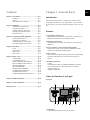
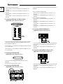
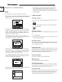
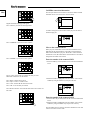
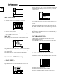
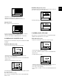
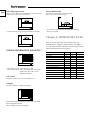
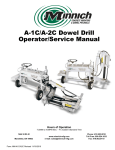
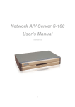
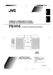
System Keyboard
SSC-2000 User's Manual
GB
F
D
ES
I
R
P
GB-2
CAUTION
RISK OF ELECTRIC
SHOCK DO NOT OPEN
CAUTION : TO REDUCE THE RISK OF ELECTRIC
SHOCK, DO NOT REMOVE COVER (OR
BACK). NO USER SERVICEABLE PARTS
INSIDE. REFER SERVICING TO QUALIFIED SERVICE PERSONNEL.
This symbol indicates high voltage is present
inside. It is dangerous to make any kind of
contact with any inside part of this product.
This symbol alerts you that important literature concerning operation and maintenance
has been included with this product.
To prevent damage which may result in fire or electric shock
hazard, do not expose this appliance to rain or moisture.
This device complies with part 15 of the FCC Rules.
Operation is subject to the following two conditions.
1) This device may not cause harmful interference, and
2) This device must accept any interference that may cause
undesired operation.
CAUTION
Danger of explosion if battery is incorrectly replaced.
Replace only with the same or equivalent type recommended
by the manufacturer.
Dispose of used batteries according to the manufacturer’s
instructions.
Important Safety Instructions
1.
2.
3.
4.
5.
6.
7.
Read these instructions.
Keep these instructions.
Heed all warnings.
Follow all instructions.
Do not use this apparatus near water.
Clean only with dry cloth.
Do not block any ventilation openings. Install in accordance with the manufacturer’s instructions.
8. Do not install near any heat sources such as radiators,
heat registers, or other apparatus (including amplifiers)
that produce heat.
9. Do not defeat the safety purpose of the polarized or
grounding-type plus.
A polarized plug has two blades with one wider than the
other. A grounding type plug has two blades and a third
grounding prong. The wide blade or the third prong are
provided for your safety. If the provided plug does not fit
into your outlet, consult an electrician for replacement of
the obsolete outlet.
10. Protect the power cord from being walked on or pinched
particularly at plugs, convenience receptacles, and the
point where they exit from the apparatus.
11. Only use attachments/accessories specified by the manufacturer.
12. Use only with cart, stand, tripod, bracket, or table specified by the manufacturer, or sold with the apparatus.
When a used, caution when moving the
cart/apparatus combination to avoid injury
from tip-over.
13. Unplug this apparatus. When a cart is
used, use caution when moving the cart/apparatus combination to avoid injury from tip-over.
14. Refer all servicing to qualified service personnel.
Servicing is required when the apparatus has been damaged in any way, such as power-supply cord or plug is
damaged, liquid has been spilled or objects have fallen
into the apparatus, the apparatus has been exposed to rain
or moisture, does not operate normally, or has been
dropped.
Contents
Chapter 1. General Facts
Chapter 1. General Facts ........................................................gb-3
Introduction ............................................................gb-3
Features ..................................................................gb-3
Name and function of each part ............................gb-3
Introduction
Chapter 2. Installation ............................................................gb-4
Installation Environment Setup .............................gb-4
Cautions for Installation ........................................gb-4
Checking Contents & Accessories .........................gb-5
Adjusting System Keyboard Angle .......................gb-5
Fixing Power Cord .................................................gb-5
Chapter 3. Connecting with Other Equipment ....................gb-5
Connecting RS-485 Device ...................................gb-5
Connecting PC by RS-232 .....................................gb-7
Connecting Other System Keyboard .....................gb-7
Basic System Diagram of SSC-2000 .....................gb-7
Chapter 4. Instructions ...........................................................gb-8
Log-in .....................................................................gb-8
Camera control .......................................................gb-8
DVR control ...........................................................gb-11
MUX control ..........................................................gb-11
Chapter 5. MENU setup ..........................................................gb-12
< MAIN MENU > .................................................gb-12
< KEYBOARD SETUP > .....................................gb-12
RS-485 COMMUNICATION SETUP ...................gb-12
RS-232 COMMUNICATION SETUP ...................gb-13
CHANGE PASSWORD ........................................gb-14
CHECK PASSWORD ...........................................gb-14
REGISTER NEW OPERATER .............................gb-14
CAMERA DATA DOWNLOAD ...........................gb-15
CAMERA DATA UPLOAD ..................................gb-15
SYSTEM INFORMATION AND SETUP ............gb-16
SSC-2000 system keyboard is a controller that controls Cameras,
DVR, MUX, and other devices by using RS-485. An user-friendly
on-screen menu, touch screen, and joystick applied, it is easy to operate.
Features
1) Long-distance remote control
Through RS-485 communication, remote control is possible up to 1.2
kilometers. (Based on the one SYSTEM Key Board)
2) Integrated System Control
A system keyboard can control Camera (Receiver Unit), DVR, and
Multiplexer.
3) You can connect 2 or more system keyboards together.
Maximum 32 keyboards can be connected simultaneously and the
system can be controlled from different places.
4) Easy to operate
There is an LCD showing the operating status of the system keyboard,
Touch Screen that helps users to choose the menu easily, and a
Joystick.
Controllable products List
- Camera
- DVR (SHR-3091, SHR-3161, SHR-4040, SHR-4080, SCR-3000,
PC based DVR (SPR-1116, SPR-2208, SPR-2216, SPR-4116,
SPR-4216, SPR-4416))
- Multiplexer (SDM-160)
Name and function of each part
Chapter 6. OPERATOR LEVEL ...........................................gb-16
Front side
Chapter 7. Product Specification ...........................................gb-17
Chapter 8. Q & A ....................................................................gb-17
A. LCD Display
It shows the operating status of the system keyboard.
GB-3
GB-4
B. Camera movement key
- PRESET
- PATTERN
- SCAN
- AUTO PAN
C. Alarm release key
D. Joystick controller (UP/DOWN/LEFT/DOWN/AF/ZOOM)
The Pan/Tilt connected with Samsung Dome Camera or Receiver Unit
is moved to UP/DOWN/LEFT/RIGHT. Press the button on the top of
Joystick to control the Auto Focus. And use for the zoom control by
turning to the clockwise or counterclockwise. The function of UP/
DOWN/LEFT/RIGHT keys is controlled in the menu screen of the
connected controller. Press the button of the top to execute ENTER
motion.
E. Camera lens key
- IRIS control (IRIS CLOSE/OPEN)
- FOCUS control (FOCUS NEAR/FAR)
- ZOOM control (ZOOM TELE/WIDE)
F. MENU key
This key is to go into the menu mode for the setup of various devices.
G. Device select key (MON/CAM/MUX/DVR)
This key is to select Camera, Monitor, DVR, MUX Number, or others.
H. Number key (0~9), ENTER key, CLEAR key
This key is to select Camera, Monitor, DVR, MUX Number, Preset,
Pattern Number, or others.
I. DVR control key (SEQUENCE, MODE)
- SEQUENCE : Executes the SEQUENCE function of DVR.
- MODE : Executes the partition screen selection function of DVR.
J. Jog shuttle
- JOG : Is in use for Forward / Reverse Frame search in the playback
mode of DVR.
- Shuttle : Executes the Play / Reverse Play / FF / REW functions in
the playback mode of DVR.
K. DVR play key
- PLAY/PAUSE
- STOP
- FAST FORWARD
- REWIND
- RECORD
M. RS-485
For RS-485 communication, it will be connected to the RS-485 terminals of other system keyboards or controlling devices such as cameras, DVR, and MUX.
N. RS-232
Connection port to adjust the system key board in a factory.
Chapter 2. Installation
Installation Environment Setup
The following information is prepared for safe installation of the unit.
This unit can be placed on a flat table or installed in the rack. It
should not be used vertically or skew, but horizontally. The location
of the unit and the composition of wiring are very important in properly operating the system. When equipment is placed too close or if
ventilation is not properly done, system may not work properly, and
maintenance of the system may be difficult. In order to prevent system failure and to reduce system shut-down by outside environmental
factors, air circulation in the system operating room, and the cover of
the unit must be fixed. Do not open the cover voluntarily because
high voltage within the unit may cause electric shock.
PHYSICAL & ENVIRONMENTAL
• Operating Temperature : 0 °C to 40 °C
• Temperature : -20 °C to 60 °C
• Operating Humidity : 20% to 85% (RH)
• Maintenance Humidity : 20% to 95% (RH)
• Power Supply : 12 VDC, 600mA (
• Power Consumption : less than 3W
Caution
When system is operated, input voltage range must be within 10% of
nominal voltage, and power consent should be grounded. Heating devices
such as hair dryer, iron, refrigerator should not be used together. For safe
power supply, AVR (Automatic Voltage Regulator) is recommended.
The connector linked to this equipment can affect EMI, so it is recommended to coil the CORE-FERRITE for use.
Cautions for Installation
•
•
•
•
•
Back side
•
•
•
•
L. DC 12V IN
DC 12V power input terminal.
)
Be sure to turn the unit off before installing.
Avoid shock or vibration since they may cause unit malfunction.
Keep away from magnets, radio or TV to avoid magnetic damage.
During or after installing the unit, be sure to maintain the area around the
unit clean.
Place the unit on a flat surface and maintain temperature properly. Allow
15 cm of clearance between the rear panel and the wall.
Be careful not to drop any conductive materials into the hole for ventilation
When replacing built-in fuse, be sure to turn the power off, and unplug the
unit.
Avoid locating the unit where direct sunlight will fall, and maintain it cool.
Keep tools and equipment away from people so that they would not be
hurt.
If ignoring smoke or smell while using the unit, fire or electric shock may
occur. In this case, turn the power switch off immediately, and consult professionals in the closest service center.
• Be sure to check dangers, which may occur due to damped floor,
ungrounded power extension cable, worn power cord or lack of safety
grounding.
Caution
When cleaning this unit, be sure to wipe with a dried cloth. If the unit is
heavily contaminated, wipe it with a soft cloth dampened with a mild
detergent solution, then wipe dry with a soft clean cloth. Do not use
chemicals such as alcohol, benzene, or thinner because a chemical reaction could result permanent damaging of the cabinet surface.
Checking Contents & Accessories
Chapter 3. Connecting with
Other Equipment
You can use the SSC-2000 system key board with a camera,
DVR, MULTIPLEXER, and the other equipments.
This chapter describes how to connect each equipment.
Connecting RS-485 Device
- Connect RS-485 Device through the port in the back of SSC-2000.
On buying a product, unwrap it first and put it down on a plane or
where you want to use it. Then, you shall check if the following are
contained in the box.
- You are able to install and control the camera, DVR, and multiplexer supporting RS-485 communication.
- Main Body
- User’s Manual
- Either Half Duplex or Full Duplex method is applicable for connection.
em
Syst
MENU
MON
CAN
MUX
DVR
oard
Keyb
SEQUENCE MODE
• For the Half Duplex method, use Tx +,-.
• To connect RS-485, be careful not to be confused between + and -.
Also, you shall check if the RS-485 device can support SSC-2000.
• Please refer to “RS-485 Communication Setup (GB-12)” of “Chapter 5.
Menu Setup” for RS-485 communication setup.
Adjusting System Keyboard Angle
You may adjust the angle of the product as shown below.
1) Connecting the SAMSUNG Dome Camera
Fixing Power Cord
AB70-0059A
CAUTION :
REPLACE WITH SAME TYPE
2.0A 250V FUSE
ATTTENTION :
UTILISER UN FUSIBLE DE
RECHANGE DE MEME TYPE
DE 2.0A 250V
AC 24V
OUT
Hang the power cord as shown in the following figure to prevent it
from being deviated when you connect it with the main body.
IN GND IN
POWER
ALARM OUT
1 2 G NC C NO
Txd
Txd
Rxd
VIDEO OUT
ALARM IN
G 1
2 3
4 G
Rxd
- Connect with SSC-2000 by using the RS-485 port on the back of
Dome Camera
• In case of connecting with Half Duplex
- Connect the Txd (+) of Dome Camera RS-485 port with the Tx (+) of
SSC-2000.
- Connect the Txd (-) of Dome Camera RS-485 port with the Tx (-) of
SSC-2000.
GB-5
GB-6
• In case of connecting with Full Duplex
- Connect the Txd (+) of Dome Camera RS-485 port with the Rx (+) of
SSC-2000.
- Connect the Txd (-) of Dome Camera RS-485 port with the Rx (-) of
SSC-2000.
- Connect the Rxd (+) of Dome Camera RS-485 port with the Tx (+) of
SSC-2000.
- Connect the Rxd (-) of Dome Camera RS-485 port with the Tx (-) of
SSC-2000.
2) Connecting SHR-3091 & SHR-3161 DVR
(Applicable to the Version 1.230 over)
- Connect with SSC-2000 by using the RS-485 port on the back of
SHR-4080
• In case of connecting with Half Duplex
- Connect the Tx (+) of SHR-4080 RS-485 port with the Tx (+) of
SSC-2000.
- Connect the Tx (-) of SHR-4080 RS-485 port with the Tx (-) of
SSC-2000.
• In case of connecting with Full Duplex
- Connect the Tx (+) of SHR-4080 RS-485 port with the Rx (+) of
SSC-2000.
- Connect the Tx (-) of SHR-4080 RS-485 port with the Rx (-) of
SSC-2000.
- Connect the Rx (+) of SHR-4080 RS-485 port with the Tx (+) of
SSC-2000.
- Connect the Rx (-) of SHR-4080 RS-485 port with the Tx (-) of
SSC-2000.
5) Connecting SDM-160 Multiplexer
(Applicable to the Version 2.0 over)
- Connect SSC-2000 through the Alarm Input/Output board and alarm
connector strips fixed to the Alarm I/O / RS-485 Connector in the
back of SHR-3091/SHR-3161.
- Connect DATA (+) in the RS-485 port of SHR-3091/SHR-3161 with
Tx (+) of SSC-2000.
- Connect DATA (-) in the RS-485 port of SHR-3091/SHR-3161 with
Tx (-) of SSC-2000.
- Connect SSC-2000 through the RS-485 port in the back of SDM-160.
- Connect DATA (+) in the RS-485 port of SDM-160 with Tx (+) of
SSC-2000.
- Connect DATA (-) in the RS-485 port of SDM-160 with Tx (-) of
SSC-2000.
6) Connecting SCR-3000(SSC-DAUL) DVR
(Applicable to the Version 1.01.X over)
3) Connecting SHR-4040 DVR
(Applicable to the Version 2.0 over)
- Connect SSC-2000 through the RS-232C port in the back of
SHR-4040.
- You may use the RS-232 to 485 converter.
4) Connecting SHR-4080 DVR
(Applicable to the Version 3.1 over)
- Connect SSC-2000 through the RS-485 port in the back of SCR-3000.
- Connect DATA (+) in the RS-485 port of SCR-3000 with Tx (+) of
SSC-2000.
- Connect DATA (-) in the RS-485 port of SCR-3000 with Tx (-) of
SSC-2000.
7) Connecting PC based DVR
(Applicable to the SPR Smart View V2.3 over)
- Connect the Tx (+) of SSC-2000 port with the Tx (+) of another SSC-2000.
- Connect the Tx (-) of SSC-2000 RS-485 port with the Tx (-) of another
SSC-2000.
2) In case of connecting with Full Duplex
- Connect SSC-2000 through the RS-485 port in the back of PC BASED
DVR.
- Connect SIGNAL (+) in the RS-485 port of PC BASED DVR with Tx (+)
of SSC-2000.
- Connect SIGNAL (-) in the RS-485 port of PC BASED DVR with Tx (-)
of SSC-2000.
- Connect the Tx (+) of SSC-2000 with the Rx (+) of another SSC-2000.
- Connect the Tx (-) of SSC-2000 with the Rx (-) of another SSC-2000.
- Connect the Rx (+) of SSC-2000 with the Tx (+) of another SSC-2000.
- Connect the Rx (-) of SSC-2000 with the Tx (-) of another SSC-2000.
Basic System Diagram of SSC-2000
1) One Keyboard to One Device
Connecting PC by RS-232
Connect a PC in which a terminal emulation program is installed to
update the S/W of this equipment. Here, you may use the RS-232C
for connection.
RS-232C Port(D-SUB 9PIN)
MENU
MON
CAN
MUX
DVR
SEQUENCE
Digital Video
Recorder
MODE
2) One Keyboard to Multiple Device (“Daisy-Chain” Type Wiring)
RS-232C 9PIN(Connector Arrangement)
PIN NUMBER
2
3
5
1, 4, 6~9
PIN SPECIFICATIONS
TXD (TRANSMITTED DATA)
RXD (RECEIVED DATA)
SG (SIGNAL GROUND)
NO CONNECTION
• Please refer to “RS-232 Communication Setup (GB-13)” of “Chapter 5.
Menu Setup” for RS-232 communication setup.
MENU
MON
CAN
MUX
DVR
SEQUENCE
Digital Video
Recorder
MODE
Digital Video
Recorder
3) Multiple Keyboards to Multiple Device
(“Daisy-Chain” Type Wiring)
Connecting Other System Keyboard
• It is possible to connect and use max. 32 keyboards simultaneously.
• Refer to the “ADDRESS SET” part in “RS-232 Communication Setup
(GB-13)” of “Chapter 5. Menu Setup” for the setting of keyboard
communication.
• Do not use together with the SSC-1000 because it is different with the
SSC-1000 in communication method.
MENU
MON
CAN
MUX
DVR
SEQUENCE
MODE
MENU
MON
CAN
MUX
DVR
SEQUENCE
MODE
Digital Video
Recorder
Digital Video
Recorder
1) In case of connecting with Half Duplex
• Do not use together with the SSC-1000 because it is different with the
SSC-1000 in communication method.
When using the system by connecting with SCC-931T Version 1.4, make the
address of devices connected to the system different.
GB-7
GB-8
Chapter 4. Instructions
Log-in
If the key board is not operated for three seconds, the graphic
panel is changed to the sleep mode and the screen is not displayed.(Blue Screen display) Press the touch panel/key or move
the joystick/joy shuttle, and then the screen before the sleep mode
is displayed again.
1. Turn on the power of all the components of the system.
2. When the power is applied by connecting the power adapter at the
back of system keyboard, the following indication is displayed on
the LCD screen.
Camera control
Selecting a camera
1. Press “CAM” key. The camera display part of the screen will be as
follows.
2. Enter the camera number (0~255) you want by using the number
key and press ENTER.
3. Using the keypad of the touch screen or the number key of the
keyboard, enter the registered Operator number (1~32) and press
“Enter”. The default Operator No. is 1. Refer to “Chapter 5.
MENU setup”, REGISTER NEW OPERATOR (GB-14) for the
registration of the operator number.
If an unregistered operator number is entered, a message of
“Invalid Operator” will appear on the screen and the log-in process
will return to the starting point automatically.
Selecting a monitor
This function is to choose a monitor displaying the image of the camera.
1. Press the MON key.
2. Enter the monitor number(0~255) that shows the image of the chosen camera and press ENTER.
PAN/TILT control
Move the joystick of the keyboard to regulate PAN/TILT of the camera. The speed of the camera movement gets faster when the joystick
moves farther from the center.
ZOOM movement
4. Using the number keys, enter the registered Password (6-digit
figure) and press “Enter”. The default Password is 123456. Refer
to “Chapter 5. MENU setup”, REGISTER NEW OPERATOR
(GB-14) for the registration of the password.
If an unregistered password is entered, a message of “Invalid
Password” will appear on the screen and the log-in process will
return to the starting point automatically.
Turn the joystick of the keyboard in a clockwise direction or press the
ZOOM TELE button to regulate the ZOOM IN movement.Turn the
joystick of the keyboard in a counterclockwise direction or press the
ZOOM WIDE regulate the ZOOM OUT movement.
FOCUS movement
Press the FOCUS FAR or FOCUS NEAR button.
IRIS movement
Press the IRIS OPEN or IRIS CLOSE button.
AUTO PAN movement
Press the auto pan button to move between two points in the camera
menu repeatedly. “AUTO PAN” will appear on the screen. Press the
AUTO PAN button again to release the auto pan mode.
5. When the log-in process is completed properly, the camera control
mode will appear on the screen as shown below.
SCAN movement
This function is to move between the preset positions that were set by
the camera's scan mode. Press “SCAN” button to execute the scan
movement and you will see “SCAN” message during the scan movement. Press the scan button again to release the scan mode.
PATTERN movement
PRESET DELETE
This function is to view the camera movement for 30 seconds designated by the user on the pattern mode of the camera menu. Press the
pattern button on the keyboard, enter the pattern number(1~3) you
want, and press “ENTER” to execute PATTERN movement.
“PATTERN 1” will appear on the screen.
• If there is any of MANUAL (PAN, TILT, ZOOM, FOCUS) input during auto
execution (SCAN, AUTO PAN, PATTERN), the system will stop the AUTO
movement and execute the MANUAL movement.
This function is to delete the preset position.
1. Press “DELETE”.
PRESET movement
Press the preset key on the keyboard to start PRESET POSITION
movement.
The screen will appear as shown below.
PRESET position movement
1. Enter the preset number you want to operate.
2. Press “ENTER” key.
2. When a window appears as shown below, enter the preset number
you want to delete and press “ENTER”.
3. The camera will move to the preset position you want to delete.
The system keyboard will show a message to confirm the deletion.
Press “OK” to delete or “CANCEL” to cancel the order.
PRESET programming
This function is to set the camera screen the user wants to call and
monitor whenever he/she wants to.
Maximum 128 screens can be preset. (0~127)
1. Move the camera to the position you want by using a joystick and
camera lens key.
2. Press “SAVE”.
Clear PRESET mode
Press “EXIT” on the right below to go out of the PRESET mode.
It will return to the camera control mode.
3. When a window appears as shown below, enter the preset number
you want to save and press “ENTER”.
CAMERA TITLE input
You can title the selected camera.
Press the camera title line to call the title input page on the screen.
GB-9
CAMERA connection information
GB-10
Press the part marked as shown below to know the number of DVR
and MUX that are con nected to the selected camera.
English small letter input page will appear.
Press “TEXT” if you want to enter large letters.
A window will appear as shown below when you press the camera
number display part.
Press “NUMBER” if you want to enter numbers.
Move to the connected device
When you press “DVR 000” on the connection information screen,
DVR 000 will be selected and the screen will be changed into the
DVR control mode.When you press “MUX 000” on the connection
information screen, MUX 000 will be selected and the screen will be
changed into the MUX control mode.
Press “SYMBOL” if you want to enter symbols.
Enter the number of the connected DVR
1. Press the DVR key of the keyboard on the connection information
screen.
Press a word at a time until you complete the title you want.
Maximum 14 characters can be entered.
Press “Back” to delete the last word.
Press “Space” to leave a column vacant.
Press “Clear” to delete all the characters entered.
Press “OK” to save the title you entered.
2. While the number is highlighted, enter the number of the connected DVR by using the number keys and press the enter
Press the EXIT ICON to cancel the title and return to the camera control mode.
Enter the number of the connected MUX
1. Press the MUX key of the keyboard on the connection information
screen.
2. While the number is highlighted, enter the number of the connected MUX by using the number keys and press the enter key.
Press the EXIT ICON to clear the connection information screen and
return to the camera control mode.
CAMERA MENU
DVR channel selection
Press the “SETUP” ICON on left below to control the menu of the
selected camera.
1. Press the “CH” ICON below on the DVR screen.
2. A channel selection screen will appear as shown below.
Using the direction key and the enter key, control the CAMERA
MENU.
Press the EXIT ICON to clear the camera menu.
3. Select the channel you want.
4. Press the EXIT ICON on the lower right to finish selecting and
return to the DVR control screen
• DVR channel can be selected by using the number keys (0~9) of the
keyboard.
DVR MENU
Press the setup icon on the lower left to control the menu of the
selected DVR.
• When you control the menu of SAMSUNG DOME CAMERA, you can
use the joystick as a direction or enter key by moving it or after pressing
the AF button of it.
DVR control
Please refer to the manual of each DVR since DVR’s functions are
varied depending on the model.
DVR selection
1. Press the DVR key.
2. Enter the DVR number (0~255) you want by using the number
keys and press ENTER.
3. Varied window will appear depending on the DVR model.
Ex) SHR-4080
Using the direction key and the enter key, control the DVR MENU.
You can use the joystick as a direction or enter key by moving it or
using the AF button.
Press the EXIT ICON to finish controlling the DVR MENU.
MUX control
SDM-160 can be controlled. Please refer to the manual of SDM-160
for detailed explanation.
MUX selection
1. Press the MUX key.
2. Enter the MUX number (0~255) you want by using the number
keys and press ENTER.
3. A window will appear as shown below.
• If you press the DVR key in the Camera Control or MUX Control mode,
the DVR Input Box will be displayed in the screen as follows. Then, select
DVR in the same manner as above.
• If you press the MUX key in the DVR Control mode, the MUX Input Box
will be displayed in the screen as follows. Then, select MUX in the same
manner as above.
GB-11
Using the number keys, enter the correct Operator No. and Password.
MAIN MENU will be displayed on the screen when you complete
the log-in process.
GB-12
MUX channel selection
1. Press the “CH” ICON below on the MUX screen.
2. A channel selection screen will appear as shown below.
Press the item you want to control on the main menu.
Press the EXIT ICON in the main menu to return to the camera control mode.
• If the CHECK PASSWORD item is set “Off” in the keyboard setup, press
the “MENU” button. MAIN MENU screen will directly appear without the
log-in process.
3. Select the channel you want.
4. Press the EXIT ICON on the lower right to finish selecting and
return to the MUX control screen
MUX MENU
Press the setup icon on the lower left to control the menu of the
selected MUX.
• If you press the menu button while the OPERATOR's LEVEL is the
MANAGER’s or OPERATOR's level, there will be a short alarm and you
cannot go into the menu.
< KEYBOARD SETUP >
On MAIN MENU, press “KEYBOARD SETUP” to call the
KEYBOARD SETUP screen.
The KEYBOARD SETUP menu are constituted by 8 main items as
follows.
Using the direction key and the enter key, control the MUX MENU.
You can use the joystick as a direction or enter key by moving it or
using the AF button.
Press the EXIT ICON to finish controlling the MUX MENU.
RS-485 COMMUNICATION SETUP
Chapter 5. MENU setup
On the KEYBOARD SETUP menu, press “RS-485 COMMUNICATION SETUP” and the RS-485 COMMUNICATION SETUP menu
will appear on the screen.
< MAIN MENU >
Press the menu button of the keyboard and a log-in window will
appear as follows.
• The default address of the keyboard is 0.
• The default BAUD RATE of the keyboard is 9600BPS.
• The factory default setting of duplex of keyboard is HALF DUPLEX.
ADDRESS SET
The address of the system keyboard can be set.
Press “ADDRESS SET” and the keyboard address input window will
appear as shown below.
Enter the address by using the number keys and press the enter key.
Press enter the “EXIT” ICON on lower left if you want to clear the
window without entering the address.
• The ADDRESS of the keyboard can be set as 0 ~ 32.
• - ADDRESS “0” : STAND ALONE
- ADDRESS “1” : MASTER
- ADDRESS “2~32” : SLAVE
• If you use a keyboard, it should be set to “0”.
• If you use 2 or more keyboards, you should set one of them to “1” and others to other numbers between “2~32”. There can be errors in communication if you set any of them to “0”.
RS-232 COMMUNICATION SETUP
The default setup for the RS-232 communication of the keyboard is
as follows.
- BAUD RATE : 4800
- DATA BIT : 8
- PARITY CHECK : NONE
- STOP BIT : 1
ADDRESS SET
Same as the address set of RS-485 COMMUNICATION.
BAUD RATE
The BAUD RATE of RS-232 communication can be set.
Press “BAUD RATE” and a pop-up window will appear as shown
below.
BAUD RATE
The BAUD RATE of the RS-485 communication can be set.
Press “BAUD RATE” and a pop-up window will appear as shown
below.
RS-232 communication of the system keyboard supports Baud Rate
as follows.
600 / 1200 / 2400 / 4800 / 9600 / 19200 / 38400 / 57600
Among these 8 kinds of BAUD RATE, select one BAUD RATE.
RS-485 communication of the system keyboard supports Baud Rate
as follows. 4800/ 9600/ 19200/ 38400
Among these 4 kinds of BAUD RATE, select one BAUD RATE.
DATA BIT
The BAUD RATE of RS-232 communication can be set.
Press “DATA BIT” and a pop-up window will appear as shown
below.
DUPLEX
You can set the duplex mode of system keyboard.
Press “DUPLEX”, and then the following window pops up.
Choose one between 7 / 8.
FULL DUPLEX / HALF DUPLEX
Select one of the two duplex. Press the exit icon on the lower left to
finish RS-485 COMMUNICATION SETUP control and return to the
KEYBOARD SETUP screen.
GB-13
GB-14
PARITY CHECK
Confirm New Password
The PARITY BIT of RS-232 communication can be set.
Press “PARITY CHECK” and a pop-up window will appear as shown
below.
This is to confirm the new password. Enter the password by using the
number keys (0~9) and press the enter key. If the entered number is
not same as the New Password, an error message “Invalid
Password!!” will be displayed on the screen. You have to start again
from entering the operator’s number.
CHECK PASSWORD
Select one among None / Odd / Even.
STOP BIT
The STOP BIT of RS-232 communication can be set.
Press “STOP BIT” and a pop-up window will appear as shown below.
If it is set “On”, a window will appear to ask the operator no. and
password when you entering the “Menu” screen.
If it is set “Off”, you can directly enter the “Menu” mode.
• The system has been set “On” on shipment.
REGISTER NEW OPERATER
This function is to add a new user of the keyboard.
Choose one between 1 / 2.
CHANGE PASSWORD
This function is to change the operator's password of the system keyboard.
New Operator No.
Enter a new operator's number.
The number can be one between 1 and 99.
Using the number keys 0~9, enter the operator's number and press the
enter key.
At first, enter the current Operator No. and Password.
Correctly entered, the screen will change into a window as follows.
New Operator No.
Enter a new password. Maximum 6-digit figure can be entered.
Using the number keys 0~9, enter the password and press the enter
key.
Confirm New Password
New Password
Enter the new password. Maximum 6-digit figure can be entered.
Enter the password by using the number keys (0~9) and press the
enter key.
This is to confirm the new password. Enter the password by using the
number keys (0~9) and press the enter key.
If the entered number is not same as the New Password, an error
message “Invalid Password!!” will be displayed on the screen. You
have to start again from entering the operator's number. A window
will appear as shown below when the confirm process is completed.
DOWNLOAD process screen
A download process screen will appear as shown below when you
press “OK” on the down load check screen.
- Operator No. : Newly registered use's number
- Password : New password is displayed.(******)
- Operator Level : The level of the new user can be set.
A message will appear when downloading is completed.
Operator Level
Press “Operator Level” to set the level.
You can choose one level among Admin. / Manager / Operator.
• DEFAULT OPERATOR LEVEL is OPERATOR level.
Please refer to the chapter 6.”OPERATOR LEVEL” for the details.
CAMERA DATA DOWNLOAD
This function is to download the setup data of SAMSUNG DOME
CAMERA.
CAMERA DATA UPLOAD
This function is to download the data set in SAMSUNG DOME
CAMERA and upload them to a new camera.
UPLOAD check screen
- If there is no camera data stored in the system keyboard
DOWNLOAD check screen
- If you want to download the data for the first time
Camera DATA uploading is not possible.
Press “OK” “CANCEL” “EXIT” to return to the KEYBOARD
SETUP screen.
- If camera DATA are stored
Download the setup data of the currently selected camera.
Press “OK” to start downloading.
Press “Cancel” or the EXIT ICON to return to the KEYBOARD
SETUP screen.
- If there are downloaded data on the system
A message will appear to inform that the camera data, which are
now stored, will be uploaded to the selected camera.
Press “OK” to start uploading
Press “Cancel” or “EXIT” to return to the KEYBOARD SETUP
screen.
An informing message will appear if there is already data stored in
the system keyboard.
Press “OK” to start downloading.
Press “Cancel” or the EXIT ICON to return to the KEYBOARD
SETUP screen.
GB-15
GB-16
UPLOAD progress screen
Factory Default Setup
When you press “OK” on the UPLOAD check screen, UPLOAD
progress screen will appear as shown below.
Resets all of the menu values to the default value.
Press “OK” to start the default setting.
‘Complete’ message will appear when uploading is completed.
• The system will start again when the FACTORY DEFAULT
SETUP is completed.
Chapter 6. OPERATOR LEVEL
There are 3 levels of user, who can be registered as a user,
including Admin. / Manager / Operator. Admin. is the highest
level. The range and limit to the usage of various setup menu and
system function depends on the user's level.
SYSTEM INFORMATION AND SETUP
- S/W Version : Present version. Setup impossible.
- Factory Default Setup : Reset all the menu values to the initial
default value. Press “OK” to start
DEFAULT SETTING.
S/W Version
Displays the present version. It is not available to set.
Language
Press the “Language” to change the language.
System keyboard supports English, Français, Deutsch, Español,
Italiano, êÛÒÒÍËÈ, and Polski.
Select a language among these languages.
Camera Setup
DVR Setup
MUX Setup
Preset Save
Preset Delete
Save Camera Title
MENU Button
Save Connect Information
Save Connected Monitor
Move Jog/Shuttle
Move Joystick
DVR Search
Select Camera/DVR/MUX
Admin.
O
O
O
O
O
O
O
O
O
O
O
O
O
Manager
X
X
X
O
O
X
X
O
O
O
O
O
O
Operator
X
X
X
X
X
X
X
X
X
X
X
X
O
Chapter 7. Product Specification Chapter 8. Q & A
ITEM
INTERFACE (RS-485)
INTERFACE (RS-232C)
LCD PANEL
LED
PAN/TILT &
LENS CONTROL
DVR CONTROL
POWER
POWER CONSUMPTION
DIMENSIONS (WxHxD)
WEIGHT (kg)
DESCRIPTION
CONNECTOR TYPE : 4P TERMINAL TYPE
PORT : 1 PORT
BAUD RATE : 4,800/9,600/19,200/38,400bps
CONNECTOR TYPE : D-SUB 9P
PORT : 1 PORT
BAUD RATE : 600/1,200/2,400/4,800/
9,600/19,200/38,400/57,600bps
5.7” GRAPHIC PANEL (320X240line) + TOUCH
PANEL
VIEWING ANGLE : LEFT(39º),RIGHT(32º),
REAR(10º), FRONT(30º)
INCLINATION ANGLE : MIN(8.4º), MAX(15.9º)
MONITOR, CAMERA, MULTIPLEXER, DVR
PAN : LEFT/RIGHT
TILT : UP/DOWN
IRIS : CLOSE/OPEN
FOCUS : FAR/NEAR
ZOOM : TELE/WIDE
PRESET, PATTERN, AUTO PAN, SCAN
SW : RW, STOP, PLAY, FF, REC.
JOG/SHUTTLE : FORWARD/REVERSE,
PLAY/REVERSE PLAY/FF/RW
DC12V, 600mA
BELOW 3W
NET : 490 x 197x 282
PACKAGE : 496 x 206x 288
NET : 1.36Kg
PACKAGE : 2.6Kg
The system keyboard communication is not worked.
- Check the RS-485 communication line.
- Check the address setup of system keyboard.
Refer to “RS-485 COMMUNICATION SETUP (GB-12)” of
“Chapter 5. Menu setting” for the method of address setup.
The password in the screen of system log in is lost.
- Apply the power in the state of pressing the “MENU” and
“ENTER” button of system keyboard at the same time.
- Press buttons until the “Beep” sounds.
- System is reset to the factory default with a “Beep” sound.
- Log in after the completion of reset.
Refer to “Log-in (GB-8)” of “Chapter 4. Instructions” for the
method of login.
• Replace the LCD panel when its expected life is over.
GB-17
GB-18