1
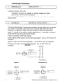
2 Way LCD Vehicle Security and
Remote Start System
IMPORTANT NOTE: The operation of the Security and Convenience System as described in this manual is
applicable to most vehicles. However, due to the configuration of some vehicles, some functions AND/OR
SAFETY PRECAUTIONS may not apply. Please see your installing dealer for more information.
2009 Audiovox Electronics Corporation. All rights reserved.
4280211
Table of Contents
Using Your Remote Control
3
Arming the Security System
Passive Arming Bypass
Bypassing the Shock Sensor
Hidden Alarm Function
Disarming the Security System
Two Stage Door Unlock (optional)
Valet Mode
Manually Overriding the Security System
Activating Trunk Release (optional)
Activating Optional AUX 1 (optional)
Using the Progressive Car Finder Feature
Using the Personal Protection Alarm
Eliminating Arm / Disarm Notification Chirps
Car Jack Mode
Using Your Remote Vehicle Starter
6
Remote Starting Your Vehicle
Entering Your Vehicle while it is Running via Remote Start
Preheating or Precooling the Vehicle's Interior
Using the "Quick-Stop" Feature
Operating the 2/3 Hour Start Up Timer Mode
Turbo Timer Mode (optional)
Operating the Daily Start Timer
Remote Start Safety Features
LED and Siren/Horn Indications
2
3
3
3
3
3
4
4
4
4
4
5
5
5
5
6
6
6
6
7
7
8
8
9
Additional 2-Way LCD Remote Control Functions
10
LCD Remote Control ICON's
12
Transmitter Button Functions
13
Replacing Remote Control Batteries
15
Warranty Information
17
2009 Audiovox Electronics Corporation. All rights reserved.
Using Your Remote Control
Arming the Security System
To arm the system, exit the vehicle, close all doors, then press the ~ button. The
parking lights will flash 2 times, indicating the system is armed, has locked the
doors (if equipped and connected) and activated the starter disable feature. The
LED status indicator will blink steadily, once per second.
NOTE: The system is defaulted with Silent Choice enabled, which requires a
second press of the r?1 button to activate an audible arming response from the
vehicle.
Passive Arming Bypass
If passive arming is enabled on your system, while the system is disarmed, press
c? + ~»)), the system will respond with 1 chirp and the LED will turn on. The
security system will remain in this temporally bypassed state for as long as you
wish. To exit passive bypass, press the (g] or ~ button and the system will return
to normal status.
Bypassing The Shock Sensor
To arm the system and ignore the shock sensor press ff: button, then within 5
seconds press &J + ~»)) , the system will respond with 1 long chirp.
NOTE: The system will only change the shock sensor setting for one arm cycle
and will be defaulted back to normal operation the next time the system is armed.
Hidden Alarm Function
Press the c:J»)) button first, within 3 seconds press the lE button to activate the
hidden alarm function. The security system will arm with "Hidden Alarm Function"
in which the siren I horn will be silenced if the system is triggered.
Disarming the Security System
To disarm the system press the GJ button. The parking lights will flash 1 time,
indicating the system is disarmed and has unlocked the doors (if equipped and
connected).
NOTE: The system is defaulted with Silent Choice enabled, which requires a
second press of the riJ button to activate an audible arming response from the
vehicle.
'Throughout this manual, 'press' refers to pressing for less than 1 second; 'press and hold' refers to pressing for more
than 2 seconds.
2009 Audiovox Electronics Corporation. All rights reserved.
3
Two Stage Door Unlock (Optional)
If this feature is enabled on your system, pressing the
button one time will
unlock only the driver's door. Press
again within three seconds to unlock the
remaining doors.
Valet Mode
To engage valet mode:
1. Turn the ignition key to the ON position.
2. Press and hold the emergency override button.
3. The LED will light solid indicating that the system is in valet mode.
When valet mode is activated the status LED will light solid, and all security and
remote start functions will be disabled.
To disengage valet Mode:
1. Turn the ignition key to the ON position.
2. Press and release the emergency override button.
3. The LED will turn off indicating that the system has exited valet mode.
Manually Overriding the Security System
Your system can be disarmed without the use of the transmitter. This is
necessary, since you will need the ability to operate your vehicle if the transmitter
is lost or its battery fails. To by-pass the alarm system;
1. Open the vehicle door. The alarm will sound.
2. Turn the ignition key to the ON position.
3. Within 5 seconds, press and release the valet push button switch.
The alarm system will stop sounding and enter the (by-passed) mode. You can
now start and operate the vehicle normally.
Activating the Trunk Release Feature (Optional)
If this feature is enabled on your system, pressing and holding the
seconds will open the vehicle's trunk or hatch.
:i1
button for 3
Activating Optional AUX 1 (Optional)
If this feature is enabled on your system, pressing the @ and :i1 buttons
simultaneously will activate an optional feature. This feature can be programmed
for a wide range of functions like power window or sunroof automation, please
consult your installing dealer to determine the functionality of your system.
4
2009 Audiovox Electronics Corporation. All rights reserved.
Using the Progressive Car Finder Feature
Press the c:J))) button to locate your vehicle. The system will sound 5 times at low
volume, increasing in volume each time the button is pressed.
Using the Personal Protection Alarm (Panic)
Press and hold the c:J))) button for 3 seconds to activate the personal protection
alarm. During panic mode, the normal function of the transmitter buttons will be
suspended. The transmitter's rm and £ buttons can be used to lock and unlock the
door (if the option is installed). To stop the alarm, press and hold the c:J))) button on
the transmitter again for 3 seconds. The system will automatically stop after 30
seconds.
Eliminating Arm / Disarm Notification Chirps
System ARM/DISARM chirps can be toggled ON or OFF without entering the
programming feature banks.
1. Turn the ignition ON then OFF.
2. Press and release the valet/programming button 3 times. The system will
respond with 1 chirp for ON or 2 chirps for OFF.
Car Jack Mode
This feature must be turned on in system programming, please consult your
installing dealer.
Triggering Car Jack mode: While the ignition is ON and press and hold I:I) + CiJ for 2
seconds, the parking lights will flash 1 time and the system will act as follows;
1.
50 seconds after being triggered the siren will chirp for 15 seconds,
during this 15 seconds you will be alerted to push the valet button to turn
off Car Jack mode. If Car Jack mode is not turned off at this time it will
advance to the next step.
2.
Following the 15 second chirps (total time now 65 seconds) the siren
will go into full sound and the parking lights will start flashing.
3.
90 seconds after trigger in, addition to the siren and parking lights, the
system will activate the starter kill. THE SYSTEM WILL REMAIN IN THIS
STATE UNTILTHE BATTERY IS DEPLETED.
OVERRIDE THE SYSTEM TO TURN OFF CAR JACK MODE: Turn the ignition OFF
then On and press the valet button within 10 seconds.
2009 Audiovox Electronics Corporation. All rights reserved.
5
Using Your Remote Vehicle Starter
Remote Starting Your Vehicle
To activate the remote vehicle start function, press and release the 0 button 2
times within 2 seconds. The system will sound, the parking lights will flash 1 time
and the system will check the vehicle to ensure it is safe to start. If all safety
parameters are correct, the vehicle will start within 5 seconds. The vehicle's
parking lights will turn on (or flash depending on system settings) as a visual
indication that the vehicle has started and is running. Press and hold the 0) button
for 3 seconds to turn the vehicle off.
If your vehicle stalls or does not start, the system will pause 5 seconds, then try 2
more times to start the vehicle (a total of 3 attempts). The system will pause 5
seconds between each start attempt. If the vehicle does not start after the 3rd
attempt, the system will abort the remote vehicle start process.
Entering the Vehicle while it is Running via Remote Vehicle Start
1. Unlock the vehicle's doors.
2. Enter the vehicle. DO NOT PRESS THE BRAKE PEDAL!
3. Insert the key into the ignition switch and turn to the ON or RUN position.
4. Press the brake pedal. The remote vehicle starter will disengage and the
vehicle will operate normally.
Preheating or Precooling the Vehicle's interior
Before exiting the vehicle, set the temperature controls to the desired setting and
operation. After the system starts the vehicle, the heater or air conditioner will
activate and heat or cool the vehicle's interior to your setting.
Using the "Quick-stop" Feature
If you want to make a short stop and keep your vehicle running (to keep the
interior warm or cool), the quick-stop feature allows you to do this while keeping
your vehicle secure and your keys with you.
To engage quick stop:
1. Stop the vehicle and place the transmission in PARK.
2. With your foot off the brake pedal, press and release the 0 button 2
times within 2 seconds. The LED will flash 3 times to confirm quick stop is
entered.
3. Remove the keys from the ignition and exit the vehicle. Press the @
button to lock the vehicle's doors if desired.
Note: Do not leave children or animals unattended in the vehicle when using the
quick-stop feature.
6
2009 Audiovox Electronics Corporation. All rights reserved.
Operating the 2 / 3 Hour Start Up Timer Mode
The system has the ability to start the vehicle every 2 or 3 hours for a 48 hour
period. This feature is especially useful in cold climates where the only means to
keep the engine and engine fluids warm is to periodically start the engine. The
default setting is 3 hour, Selection between 2 or 3 hour is made in option
programming.
WARNING!
Be certain that the vehicle is outdoors before using this or any remote starting
device. A running engine produces dangerous carbon monoxide fumes which can
be harmful or fatal if prolonged exposure occurs. DO NOT remote start the vehicle
if it is garaged.
To begin the 2 I 3 hour start up timer mode:
1.
Turn the vehicle's ignition ON then OFF.
2.
Press and hold the valet button.
3.
Press the n button 4 times, the system will chirp 2 times and flash the
parking lights 4 times.
4.
Release the valet button.
To exit the 2 I 3 hour start up timer mode:
1.
Turn the vehicle's Ignition ON.
OR
1.
Activate the remote vehicle start feature using the remote control.
Turbo Timer
This option will keep the engine running to allow the vehicle's turbo to properly cool
down before shutting the engine off.
To engage the Turbo Timer feature:
1.
With the vehicle running via the ignition key and your foot off of the
brake pedal.
2.
Engage the vehicle's parking brake and press the
buttons simultaneously.
~
and
n
3.
The vehicle's parking lights will turn on to verify the Turbo Timer
feature has been activated.
4.
Turn the ignition key OFF, the vehicle will continue to run until the preprogrammed time has elapsed (1, 3, or 5 minutes)
To disengage the turbo timer feature, press the vehicle's brake pedal.
2009 Audiovox Electronics Corporation. All rights reserved.
7
Operating the Daily Start Timer
The system has the ability to start your vehicle based on a 24-hour countdown
timer. This feature requires a two-part activation sequence. From the remote,
pressing both the ® & n buttons together will activate the 24 hour countdown
timer (the vehicle will start 24 hours from this time). Next, When you are finished
operating the vehicle for the day, perform the following steps to complete the
process.
1.
Turn the ignition ON/OFF (vehicle must be disarmed).
2.
Within 10 seconds, while pressing the brake, press and release the {J
button twice.
3.
The vehicle will emit 2 chirps.
Remote Start Safety Features
For safety and security reasons, the system will shutdown or prevent the remote
vehicle starter from activating if any of the following occur:
1.
The vehicle hood is open.
2.
The brake pedal is pressed prior to turning the ignition key to the ON
position.
8
3.
The engine is over-revved (tach checking only).
4.
Valet mode is active.
2009 Audiovox Electronics Corporation. All rights reserved.
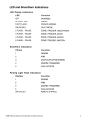
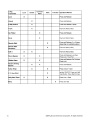
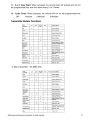
LED and Siren/Horn Indications
LED Display Indications
LED
Function
OFF
DISARMED
SLOW FLASH
ARMED
FAST FLASH
PASSIVEARMING
ON (SOLID)
VALET MODE
2 FLASH
PAUSE
ZONE 2 TRIGGER, HOODfTRUNK
3 FLASH
PAUSE
ZONE 3 TRIGGER, DOOR
4 FLASH
PAUSE
ZONE 4 TRIGGER, SHOCK
5 FLASH
PAUSE
ZONE 5 TRIGGER, IGNITION
Siren/Horn Indications
Chirps
Function
1
DISARM
2
ARM
3
DOOR AJAR UPON ARMING
4
DISARM /TRIGGERED
5
CAR LOCATOR
Parking Light Flash Indications
Flashes
Function
1
DISARM
2
ARM
3
DISARM /TRIGGERED
5
CAR LOCATOR
ON (SOLID)
REMOTE STARTED
2009 Audiovox Electronics Corporation. All rights reserved.
9
Additional2-Way LCD Remote Control Functions
Check Vehicle Status
Press and release j'c~ 2 times then press 191 within 3 seconds, the transmitter will
respond with one melody sound and display the current status of the vehicle.
Display Illumination
Press and hold the ie button for 1 second. The display will illuminate for 5
seconds.
Melody / Vibration Mode
To have the remote control vibrate, playa melody tone or both each time it receives
a response from the vehicle press and release
then press and hold for 2
seconds.
Button Beeps
To toggle button beeps on or off press and release
seconds.
r;
then press and hold
for 2
Battery Save Mode
While in POWER SAVE MODE the 2-way LCD transmitter will NOT look for any
incoming signals from the main unit until a button is pressed. The LCD screen will
display SAVE to indicate that power save mode is ON. To enter power save mode
press and hold .c". for 5 seconds.
Clear Flashing Icons and Melody Sound
Press the ~ button 3 times within 3 seconds. This will clear the melody sound and
flashing icons on the LCD screen.
Stopping LCD Trigger Melody
To stop the alarm trigger melody if the system has been triggered WITHOUT
disarming the system, press any button one time only, this will not send a
command to the vehicle at this time and the alarm will continue to sound.
10
2009 Audiovox Electronics Corporation. All rights reserved.
Button Lock
Press and release
on or off.
then press hold the
for 2 seconds to toggle the button lock
Illumination
Press and release
2 times then press and hold
for 2 seconds to toggle
illumination on or off. When on, the display will illuminate when it receives or
sends a command.
2 Car Mode
To control a second security system enter 2 car mode by pressing '", then press
and @J together for 3 seconds. When the ill( icon appears on the transmitter's LCD
screen it will control the second security system. Use the same method to exit 2
car mode and resume control of the original vehicle's security system.
NOTE: A second security system must be installed and the LCD transmitter must be
learned to it before this feature will operate the additional system.
Parking Meter Countdown
The parking meter countdown timer has 6 preset times, to access the preset times
and begin countdown press and release }~ then press and hold c;J))) for 2 seconds,
repeating this step to increase the countdown time.
Adjusting the Clock and Timer Settings
The clock, alarm clock and programmable countdown timer are accessed through
the Function Menu. Press and hold ~~ for 3 seconds to access the function menu,
once you have accessed the feature menu press and release :F to scroll through
each feature and follow the steps below to adjust the settings for each. Press and
hold? for 2 seconds to exit the menu.
Clock Hour
Press
c;J)))
to increase or
to decrease
Clock Minute
Press
c;J)))
to increase or
to decrease
Alarm Clock Hour
Press
0:::)))
to increase or
to decrease
Alarm Clock Minute
Press
c;J)))
to increase or, to decrease
Alarm Clock ON / OFF
Press
c;J)))
to turn ON or ,;/ to turn OFF
Countdown Timer Hour
Press
c;J)))
to increase or
to decrease
Countdown Timer Minute
Press
c;J)))
to increase or
to decrease
Countdown Timer ON / OFF
Press
c;J)))
to turn ON or
2009 Audiovox Electronics Corporation. All rights reserved.
to turn OFF
11
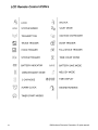
LCD Remote Control ICON's
~
LOCK
c]
UNLOCK
£~[M]
SYSTEM ARMED
~~
VALET MODE
~~21»~
TRANSMITTING
~
IGNITION ONITRIGGER
~
TRUNK TRIGGER
tEl
DOOR TRIGGER
~
HOOD TRIGGER
!fA
FULL SHOCK TRIGGER
@a~
SYSTEM TRIGGER
~IDDO:
BATTERY INDICATOR
1Ml001Ql
~~
VIBRATE/SILENT MODE
rill
2 CAR MODE
~
ALARM CLOCK
~
TIMER START MODES
~~
12
X
~~\if~
t
:88:88
TIME COUNT DOWN
BATIERY SAVE MODE
MELODY MODE
TIME DISPLAY
ENGINE RUNNING
2009 Audiovox Electronics Corporation. All rights reserved.
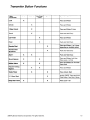
Transmitter Button Functions
1 Way
Transmitter
Lock
Lock
Unlock
Car Find /
Panic
Start
x
Operation Method
Press and Release
Unlock
x
Press and Release
2 Step Unlock
x
Press and Release 2 times
Trunk
x
Push and Hold (3 Sec)
Car Finder
x
Press and Release
Panic
x
Push and Hold (3 Sec)
Remote Start
x
Press and Release (1 or 2 times
depending on selectable option)
Remote Start
Shutdown
x
Push and Hold (3 Sec)
AUX1
x
Shock Bypass
x
x
Press and Release Lock then
Press Lock + Car Find
Hidden Alarm
x
x
Press and Release Car Fnd then
Press Lock
x
Press and Release
x
Passive Arming
Bypass
x
Turbo Timer
x
Push and Hold (3 Sec)
2 / 3 Hour Start
Daily Start Timer
x
2009 Audiovox Electronics Corporation. All rights reseNed.
x
Press Unlock + Start
x
Ignition ON/OFF, Press and Hold
Valet Button, Press Start 4 times
x
Press Lock + Start
13
2 Way
Transmitter
Lock
Lock
Car Find I
Panic
Start
Function
Operation Method
Press and Release
X
Unlock
X
Press and Release
2 Step Unlock
X
Press and Release 2 times
Trunk
X
Push and Hold (3 Sec)
Car Finder
X
Press and Release
Panic
X
Push and Hold (3 Sec)
Remote Start
X
Press and Release (1 or 2 times
depending on selectable option)
Remote Start
Shutdown
X
Push and Hold (3 Sec)
AUX 1
X
Shock Bypass
X
X
Press and Release Lock then
Press Lock + Car Find
Hidden Alarm
X
X
Press and Release Car Fnd then
Press Lock
X
Press and Release
X
Turbo Timer
X
Daily Start Timer
Menu
X
Push and Hold (3 Sec)
X
Passive Arming
Bypass
2 I 3 Hour Start
14
Unlock
X
Press Unlock + Start
X
Ignition ON/OFF, Press and Hold
Valet Button, Press Start 4 times
X
Press Lock + Start
X
Press and Hold
2009 Audiovox Electronics Corporation. All rights reserved.
Replacing Remote Control Batteries
1-Way 4 Button Remote Control:
The batteries (model CR2016) inside each remote control should last approximately 1
year under normal use. When the batteries become weak you will notice the remote
control range (the distance from the vehicle the remote control will work) deteriorate
and the small LED on the remote control will dim. To replace the remote control
batteries:
1. Remove 3 screws and disassemble the halves of the remote control.
2. Remove the old batteries, observing the +/- symbols on the batteries and
replace with new CR2016 batteries.
3. Reassemble the halves of the remote control and install the 3 screws.
4. Test operation of the remote control.
2-way LCD Remote Control:
The CR2450 battery inside the 2-way LCD remote control should last approximately 6
months under normal use. When the batteries become weak you will notice the
remote control range (the distance from the vehicle the remote control will work)
deteriorate and the BATIERY icon on the LCD remote control will show.
1. Gently slide the battery cover off of the remote control.
2. Remove the old CR2450 battery, observing the +/- symbols on the battery, and
replace with a new CR2450 battery.
3. Gently slide the battery cover on to the back of the remote control.
4. Test operation of the remote control.
2009 Audiovox Electronics Corporation. All rights reserved.
15
16
2009 Audiovox Electronics Corporation. All rights reserved.
Code Systems, Inc. Limited Lifetime Warranty
Code Systems Inc. ("CODE") warrants to the ORIGINAL PURCHASER of this CODE
vehicle security product (the "Product"), purchased from an authorized CODE dealer, that (except as
provided below) should this Product under normal use and conditions, be proven defective in
material or workmanship DURING THE LIFETIME OF THE VEHICLE IN WHICH IT WAS ORIGINALLY INSTALLED, such defect(s) will be repaired or replaced (at CODE's option) without charge for
parts directly related to repairs of the defect(s).
Switches, indicator lights, and transmitter cases are similarly warranted to the original
purchaser for a period of one (1) year from the date of purchase of the Product.
CODE accessories, sold separately, are covered by the applicable warranty accompanying the accessory.
This warranty is non-transferable, non-assignable and is voided when: (1) the Product is
removed from the vehicle in which it was originally installed; or (2) the vehicle in which the Product
was originally installed is transferred to another party.
This warranty does not apply to any product damaged by accident, physical or electrical
abuse, improper installation, alteration, or use contrary to its intended function, fire, flood, or other
natural acts.
In order for the Product to be repaired or replaced under the terms of this warranty, the
defective Product must be returned to an authorized CODE dealer and accompanied by a copy of
the retail sales receipt. The date of purchase and year, make and model of the vehicle in which the
Product was originally installed must be clearly indicated on the sales receipt.
This warranty is exclusive and CODE MAKES NO OTHER WARRANTIES EXPRESSED
OR IMPLIED. ANY IMPLIED WARRANTIES, INCLUDING ANY IMPLIED WARRANTY OF MERCHANTABILITY AND FITNESS FOR A PARTICULAR PURPOSE, SHALL BE LIMITED TO THE
DURATION OF THIS WRITTEN WARRANTY. IN NO CASE SHALL CODE BE LIABLE FOR ANY
CONSEQUENTIAL OR INCIDENTAL DAMAGES FOR BREACH OF THIS OR ANY OTHER WARRANTY, EXPRESS OR IMPLIED, WHATSOEVER.
CODE does not warrant that the Product cannot be compromised or circumvented. THE EXTENT OF
CODE'S LIABILITY UNDER THIS WARRANTY IS LIMITED TO THE REPAIR OR REPLACEMENT
PROVIDED ABOVE AND, IN NO EVENT SHALL CODE'S LIABILITY EXCEED THE PURCHASE
PRICE PAID BY THE ORIGINAL PURCHASER OF THE PRODUCT WITHOUT INSTALLATION
LABOR.
Some states do not allow the exclusion or limitation of incidental or consequential
damages, so the above limitation may not apply to you. This warranty gives you specific legal
rights and you may also have other rights which vary from state to state
2009 Audiovox Electronics Corporation. All rights reserved.
17
Audiovox Electronics Corporation.
Customer Service 1-800-421-3209
WWW.CODE-ALARM.COM
FCC COMPLIANCE
This device complies with Part 15 of the FCC rules and with RSS-210 of
Industry Canada. Operation is subject to the following two conditions:
1. This device may not cause harmful interference, and
2. This device must accept any interference received, including any interference
that may cause undesired operation.
Warning!
Changes or modifications not expressly approved by the party responsible for
compliance could void the user's authority to operate the equipment.
18
2009 Audiovox Electronics Corporation. All rights reserved.
R410-191-830
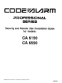
CCJ[Jc~l.A"m
P»i=lOFESSIONAL
SEi=lIES
Security and Remote Start Installation Guide
for models:
CA 6150
CA 6550
2009 Audiovox Electronics Corporation. All rights reserved.
4280208
Table of Contents
Before You Begin
4
Wire Connection Guide
5
5 Pin Main Harness
7
6 Pin Start Harness
8
6 Pin Output Harness
10
8 Pin Input Harness
11
3 Pin Door Lock Output Harness
14
Additional Ports
Antenna I LED I Programming Port
18
OBI Port
18
Set Up & Programming
2
18
19
Transmitter Programming
19
Manual Feature Programming
19
Programming Feature Banks
20
Tach Programming
21
Adjusting the Shock Sensor
22
Testing the Shock Sensor
22
Dome Light Delay I Theater Dimming
22
Chirp Delete - User Accessible
22
2009 Audiovox Electronics Corporation. All rights reserved.
Feature Descriptions
23
Transmitter Button Functions
27
Security Trigger Zones
28
Remote Start Shutdown Diagnostics
28
System Layout
29
2009 Audiovox Electronics Corporation. All rights reserved.
3
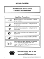
BEFORE YOU BEGIN
PROFESSIONAL INSTALLATION
STRONGLY RECOMMENDED
Installation Precautions:
~
,
:,
.....
~.
Roll down window to avoid locking keys in vehicle
during installation
Avoid mounting components or routing wires near
hot surfaces
Avoid mounting components or routing wires near
moving parts
Tape or loom wires under hood for protection and
appearance
Use grommets when routing wires through metal
surfaces
L_·_~_~·.··_._. '-:...'~J
~~
U
Use a Digital Multi Meter for testing and verifying
circuits. DO NOT USE A TEST LIGHT, OR
"COMPUTER SAFE PROBE" as these can set off air
bags or damage vehicle computers.
Technical Support (800) 421-3209
..•..
4
or go to
http://techservices.codesystems.com
2009 Audiovox Electronics Corporation. All rights reserved.
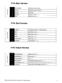
5 Pin Main Harness
WHITE/RED
PARKING LIGHT INPUT
«
WHITE
PARKING LIGHT OUTPUT
z
BLACK
GROUND
BROWN
SIREN OUTPUT ( + )
RED
BATTERY 12V (+ )
z
~
0...
l{)
6 Pin Start Harness
PURPLE
STARTER OUTPUT - MOTOR SIDE
RED
BATTERY 12V (+ )
«
RED
BATTERY 12V (+ )
z
PINK
IGNITION 1 ( + )
PINKIWHITE
IGNITION 2 ( + )
ORANGE
ACCESSORY 1 ( + )
~
0::
~
(/)
0...
<.D
6 Pin Output Harness
'-~--~~-.-----~--
HORN OUTPUT ( - )
~
IGNITION 3 ( - )
::::>
0...
~
::::>
o
VIOLET/BLACK
TRUNK RELEASE OUTPUT ( - )
z
0...
<.D
AUX 1 ( - )
LT GREEN/BLACK
FACTORY DISARM / PULSE BEFORE START (-)
GROUND WHEN ARMED OUTPUT ( - )
2009 Audiovox Electronics Corporation. All rights reserved.
5
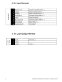
8 Pin Input Harness
BLUEIWHITE
INSTANT TRIGGER INPUT ( - )
GREEN
DOOR TRIGGER INPUT ( - )
PURPLE
DOOR TRIGGER INPUT ( + )
z
z
WHITE/BLUE
EXTRENALSTARTINPUT(-)
GRAY
HOOD PIN INPUT ( - )
ex:>
BLACKIWHITE
NEUTRALSAFETYINPUT(-)
BROWN/RED
BRAKE INPUT ( + )
PURPLEIWHITE
TACH INPUT
f-
:::>
a...
0:
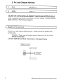
3 Pin Lock Output Harness
z~
-u
0..
0
BLUE
UNLOCK (-)
OPEN
N-J
GREEN
6
LOCK (- )
2009 Audiovox Electronics Corporation. All rights reserved.
5 Pin Main Harness
1
WHITE/RED
PARKING LIGHT INPUT
2
WHITE
PARKING LIGHT OUTPUT
Locate the parking light output wire at the vehicle's light switch.
Verification: This wire registers positive voltage when the parking lights are
turned on.
Positive switching Parking Lights:
Connect the WHITE/RED wire to a 15 Amp max fused battery source.
Connect the WHITE wire to the parking light output wire.
Negative switching Parking Lights:
Connect the WHITE/RED wire to a good chassis ground.
Connect the WHITE wire to the parking light output wire.
3
BLACK
GROUND
Connect the BLACK wire to a solid chassis ground point using a ring terminal and
self tapping screw (not supplied). Scrape away paint from the grounding point to
ensure a good connection. The recommended grounding point is a metal surface
in the driver's side kick panel area.
NOTE: Do not ground the BLACK wire with any other vehicle components.
4
BROWN
SIREN OUTPUT ( + )
Locate a suitable mounting location in the engine compartment for the siren, away
from movi ng parts.
With the bell of the siren aiming downwards, secure the siren in place using self
tapping screws, being careful not do drill into any hoses, wiring or components.
Connect the BLACK siren wire to a chassis ground using a ring terminal and self
tapping screw (not supplied).
Route the BROWN siren output wire from the control module through the firewall
and connect to the RED wire on the siren.
NOTE: Be sure to loom the siren wires, and seal the grommet.
2009 Audiovox Electronics Corporation. All rights reserved.
7
5
RED
BATIERY 12V ( +)
Locate 1 of the vehicle's constant 12 Volt battery wires at the ignition switch.
Verification: This wire will register ( + ) voltage in all positions of the ignition
switch.
Connect the RED wire to the constant 12 Volt battery wire.
NOTE: Remove all fuses until all connections are made.
6 Pin Start Harness
1
PURPLE
STARTER OUTPUT ( +)
Locate the vehicle starter wire.
Verification: This wire registers voltage only when the key is turned to the
START position. Cut the vehicle's starter wire in half when installing the
starter kill relay.
Verification after starter wire is cut:
KEY SIDE of starter wire registers voltage when the key is turned to the
START position.
MOTOR SIDE of starter wire registers no voltage.
Connect the PURPLE wire to the vehicle starter wire, use the MOTOR SIDE of the vehicle
starter wire when installing the starter kill relay.
2
RED
BATTERY 12V ( + )
Locate 1 of the vehicle's constant 12 Volt battery wires at the ignition switch.
Verification: This wire will register ( + ) voltage in all positions of the ignition
switch.
Connect the RED wire to the constant 12 Volt battery wire.
NOTE: Remove all fuses until all connections are made.
8
2009 Audiovox Electronics Corporation. All rights reserved.
3
RED
BATTERY 12V ( + )
Locate 1 of the vehicle's constant 12 Volt battery wires at the ignition switch.
Verification: This wire will register ( + ) voltage in all positions of the ignition
switch.
Connect the RED wire to the constant 12 Volt battery wire.
NOTE: Remove all fuses until all connections are made.
4
PINK
IGNITION 1 ( + )
Locate the vehicle's ignition wire at the ignition switch.
Verification.' This wire registers voltage when the key is turned to the ON (or
RUN) position. The voltage does not drop out when the key is turned to the
START (or CRANK) position.
Connect the PINK wire to the vehicle's Ignition wire.
This wire is also used for Ignition 1 Output.
5
PINK/WHITE
IGNITION 2 ( + )
Locate the vehicle's 2nd ignition wire at the ignition switch (if equipped).
Verification.' This wire registers voltage when the key is turned to the ON (or
RUN) position, but not the ACC (Accessory) position, The voltage does not
drop out when the key is turned to the START (or CRANK) position.
Connect the PINKIWHITE wire to the vehicle's ignition 2 wire,
Programmable output:
6
ORANGE
IGN, ACC, Start.
ACCESSORY 1 ( + )
Locate the vehicle's accessory wire at the ignition switch.
Verification: This wire registers voltage when the key is turned to ACC
(Accessory) and the ON (or RUN) position. The voltage drops out when the
key is turned to the START (or CRANK) position.
Connect the ORANGE wire to the vehicle's accessory wire.
2009 Audiovox Electronics Corporation. All rights reserved.
9
6 Pin Output Harness
__
1 _ _B_R_O_W_N_/B_L_A_C_K
1
H_O_R_N_O_U_T_P_U_T_(_-_)
Locate the vehicle's horn wire.
Verification: This wire will register at positive voltage and register
ground when the horn switch is pressed.
Connect the BROWN/BLACK wire to the vehicle's horn wire. This is a low current
output, SOOmA.
2
BLUE/BLACK
IGNITION 3/ ACTIVE OUTPUT ( - )
The Active Output/Ignition 3 output wire provides a ground output when the remote
start function is activated and remains until 4 seconds after the remote start is
shutdown. The Ignition 3 output wire can be used for several functions listed
below. If this wire will be used for multiple application's a 1 amp diode is required
in-line with the stripe facing the control module.
Factory transponder (coded key) bypass.
General Motors VATS bypass, see the following diagram. Use an SPOT relay (not
supplied).
Ignition 3 output, see the following diagram. Use an SPOT relay (not supplied).
Accessory 2/3 output, see the following diagram. Use an SPOT relay (not
GM VATS
supplied).
BLUE/BLACK ActiveOutput
Wire
Accessory 2/3
Ignition 3
87
Jump To PINK
Ignition Output
Wire From
Control Module
10
85
BLUEIBLACK Active Output
Wire
Jump To ORANGE
AccessolY Output
Wire From
Control Module
BLUE/BLACK Active Output
Wire
2009 Audiovox Electronics Corporation. All rights reserved.
3
VIOLET/BLACK
AUX 1
This wire provides a (-) 500mA output capable of driving relays. For Control of
optional accessories (i.e. Power Window/Sunroof, etc.).
To activate refer to the transmitter button configuration chart. Please refer to the
selectable options for timing.
4
RED/WHITE
TRUNK RELEASE OUTPUT ( - )
Locate the vehicle's trunk release wire at the trunk release switch.
Verification: This wire will register either positive voltage or ground when the trunk
release is activated.
This is a low current output, 500mA.
5
LT GREEN/BLACK
FACTORY DISARM /
PULSE BEFORE START ( - )
This wire will supply a ( - ) 500mA pulse both upon disarming the system and when
the remote start feature is activated. Locate the factory perimeter alarm disarm
wire from the key cylinder inside the drivers door.
Verification: This wire registers ground if the key is turned to the unlock
position in the driver's door cylinder.
Connect the LIGHT GREEN/BLACK wire to the factory alarm disarm wire.
6
ORANGE
GROUND WHEN ARMED OUTPUT ( - )
This wire will have a continuous ( - ) 500mA output when the system is Armed. This
wire is typically used for controlling window modules or additional sensors.
8 Pin Input Harness
1
BLUE/WHITE
INSTANT TRIGGER INPUT ( - )
This wire is a GROUND input for an external sensor or secondary pin switch.
Verification: This wire when connected will trigger the security system.
2009 Audiovox Electronics Corporation. All rights reserved.
11
2
GREEN
DOOR TRIGGER INPUT ( - )
Locate the vehicle's dome light or door pin switch wire.
Verification: This wire will register ground (NEG) when the door is opened
and the interior light is on. This wire will register positive voltage when the
door is closed and the interior light is off.
Connect the GREEN wire to the vehicle's negative door input wire(s).
NOTE: Certain vehicles may require multiple connections. Refer to vehicle
application guide
3
PURPLE
DOOR TRIGGER INPUT ( + )
Locate the vehicle's dome light or door pin switch wire.
Verification: This wire will register positive voltage (POS) when the door is
opened and the interior light is on. This wire will
register ground or "0" Volts when the door is closed and the interior light is
off.
Connect the PURPLE wire to the vehicle's positive door input wire(s).
NOTE: Certain vehicles may require multiple connections. Refer to vehicle
application guide
4
WHITE/BLUE
EXTERNALSTARTINPUT(-)
This wire will activate the Remote Start function when a GROUND pulse is applied to it
from an external device.
5
GRAY
HOOD PIN INPUT ( - )
Install a Hood Pin Switch and connect to the GRAY wire. This connection is
required for Remote Start.
Verification: This wire when connected will register ground when the
vehicle's hood is opened.
Connect the GRAY wire to the hood pin.
NOTE: Be sure to loom the wire, and seal the grommet.
12
2009 Audiovox Electronics Corporation. All rights reserved.
6
BLACKIWHITE
NEUTRALSAFETYINPUT(-)
Locate the vehicle's neutral safety circuit.
Verification: This wire registers ( - ) voltage when the vehicle's gear selector
is in park or neutral.
Connect the BLACKIWHITE neutral safety input wire to the neutral safety wire of
the vehicle or an optional toggle switch. The remote start feature will not operate
unless this input is supplied with a ground source.
7
BROWN/RED
BRAKE INPUT ( + )
Locate the vehicle's brake light wire at the brake pedal mounted switch.
Verification: This wire registers positive voltage when the brake pedal is
pressed.
Connect the BROWN/RED wire to the vehicle's brake light wire.
8
PURPLEJWHITE
TACH INPUT
Locate the vehicle's ignition coil or fuel injector in the engine compartment.
Verification: Test using the following procedure:
1.
2.
3.
4.
5.
Set voltmeter to AC VOLTS.
Attach positive lead of a volt meter to a constant 12 volt source.
Attach negative lead of a volt meter to the wire to be tested.
Start the engine.
Have someone press on the gas pedal slightly as you monitor the meter. If
connected to the correct wire, the voltage reading will increase as the engine's
RPM increases.
Connect the PURPLEIWHITE wire to the negative side of the vehicle ignition coil
or fuel injector.
2009 Audiovox Electronics Corporation. All rights reserved.
13
3 Pin Lock Output Harness
1
BLUE
UNLOCK ( -)
3
GREEN
LOCK ( - )
The door lock / unlock outputs are designed to control several different types of
systems which may require additional parts. Please review the wire and location
chart to see which type of door lock system is in your vehicle. The most common
types are shown in the following diagrams.
Negative SWitching Locks
All Door Lock and Unlock: Locate the lock / unlock wire at the vehicle's lock /
unlock switch.
Verification: These wires will register ground when the Lock and Unlock
switches are activated.
Connect the GREEN and BLUE wires shown in the diagram below.
Negative Locks:
GREEN (-j Lock Output
Vehicle Door Lock
Control Relays
BLUE (-j Unlock Output
14
2009 Audiovox Electronics Corporation. All rights reserved.
Positive Switching Locks
All Door Lock and Unlock: Locate the lock / unlock wire at the vehicle's lock /
unlock switch.
Verification: These wires will register positive voltage when the Lock and
Unlock switches are activated.
Connect the GREEN and BLUE wires shown in the diagram below.
Positive Locks:
87a
GREEN (.j Lock Output
86
30
Vehicle Door Lock
Control Relays
BLUE (.) Unlock Output
86
Reverse Polarity Locks (S-Wire Door locks)
All Door Lock and Unlock: Locate the lock / unlock wire at the vehicle's lock /
unlock switch.
Verification: These wires will rest at ground and register positive
voltage when the Lock and Unlock switches are activated.
Connect the GREEN and BLUE or BLUE/GREEN wires shown in the diagram
below using (2) SPOT relays (not supplied).
Reverse Polarity Locks:
GREEN (-) Lock Output
---------I~ To Door Lock Molar
87
BLUE (.j Unlock Output
____----I~
To Door Lock Motor
Cut
2009 Audiovox Electronics Corporation. All rights reserved.
15
Negative Multiplexed Locks
All Door Lock and Unlock: Locate the lock / unlock wire at the vehicle's lock /
unlock switch.
Verification: This wire will show variable ground when the switch is activated.
Please consult the wire and location chart for specific resistor values for
your vehicle.
Connect the GREEN and BLUE or BLUE/GREEN wires shown in the diagram
below using (2) SPOT relays (not supplied).
Multiplex Locks:
, . - - - - - - j Ground f - - - - - - ,
87
GREEN (-) Lock Oulput
f---+I
H-:-:-----i
85
___
BLUE (-j UnlOCk Output
-----1~t---
----+-------~...-~Vehicle Door Lock
Control Relays
Positive Multiplexed Locks
All Door Lock and Unlock: Locate the lock / unlock wire at the vehicle's lock /
unlock switch.
Verification: This wire will show variable positive voltage when the switch is
activated. Please consult the wire and location chart for specific resistor
values for your vehicle.
Connect the GREEN and BLUE or BLUE/GREEN wires shown in the diagram
below using (2) SPOT relays (not supplied).
Multiplex Locks:
67
I
_I-
GREEN (-) Lock Output
I
87a
86
-
Lock
-
......
Unlodc
16
U3O~
~
87
.
0
~Io
I
85
•
Fused +12 Vo~
I Battery Source I
~
• 87a
86
I
n
)30 i
85
I
BLUE H Unlock Output
(
•
1
I
I
Vehrcle DOOf Lock
Control Relays
I
2009 Audiovox Electronics Corporation. All rights reserved.
Adding Aftermarket Actuators
After installing aftermarket actuators, (not supplied). Connect the GREEN and
BLUE wires shown in the diagram below using (2) SPOT relays (not supplied) .
.__-----41-----1 Fused + 12 Volt
Battery Source
87
GREEN
(-J
Lock Output
86
. _ _ - -_ _- - - - j
87
86
2009 Audiovox Electronics Corporation. All rights reserved.
Fused + 12 Volt
Battery Source
BLUE (-) Unlock Output
17
Additional Ports
Antenna I LED I Programming Port
Mount the supplied antenna/receiver to a clear spot on the vehicle's windshield
that will not block the driver's vision. A good location is usually high on the
windshield near the rear view mirror. Be careful not to mount the antenna/receiver
on any metallic window film, as this will effect system range. Route the antenna/
receiver cable to the control module and plug into the antenna port.
Data Bus Interface Port
This 4 pin port is used for Flashlogic Door Lock and Transponder Databus
Interfaces to communicate with the vehicle's Databus. When using the OBI port to
control the Flashlogic Door Lock and Transponder Interface modules the
following options may be available. Please refer to the 020 (Data to Data)
function list available per vehicle on the tech service web site.
Tach Input
Brake Safety Shut Down
Door Trigger
Trunk/Hatch Open
Door Lock Control
Passlock / Passkey Interface (GM Only)
Dome Light Supervision
Transponder Interface Activation
Factory Alarm Arm / Disarm
Diesel Glow Plug Input
Manual Arm / Disarm Inputs (factory keyless controls system)
18
2009 Audiovox Electronics Corporation. All rights reserved.
Set Up & Programming
Transmitter Programming· Feature Bank 1
1. Turn the ignition ON.
2. Press and hold the valet/override button.
3. Within 10 seconds the system will chirp (3) three times.
4. Press 1 button of each transmitter you wish to program.
5. The system will respond with 1 chirp for each accepted transmitter.
6. Pressing the override button at anytime during programming will advance to the
next bank.
NOTE: The system will exit transmitter programming after 15 seconds of inactivity.
NOTE: This system has 1 button programming which programs all channels of the
system.
NOTE: The system will hold up to 4 transmitters in memory, programming a 5th
transmitter will erase the oldest transmitter in memory.
Transmitter programming for 2 Car Mode *2 way system only:
1. Enter the transmitter into 2 Car Mode. (Refer to transmitter operation in the
owners manual for 2 car operation)
2. Follow the steps above for transmitter programming.
NOTE: 2 car mode requires an additional security system installed in a second
vehicle.
Manual Feature Programming· Feature Bank 2 . 4
1. Turn the ignition ON.
2. Press and hold the valet/override button.
3. Within 10 seconds the system will chirp (3) three times.
4. Use the valet/override button to advance through each option bank. For
feature programming advance to Feature Bank 2, 3 or 4, which is (4) four, (5)
five, and (6) six chirps.
5. Use the transmitter () button to scroll through the selections in each feature
bank, the system will chirp to match the feature number.
6. Press the transmitter 9 button to change the desired feature. The LED will
flash indicating the changed feature.
2009 Audiovox Electronics Corporation. All rights reserved.
19
a
Defaulting All Features: Pressing the
button anytime while in any of the
feature banks will default all features and return you to feature bank 2 - 4 chirps.
NOTE: The system will remain in feature programming mode as long as the
ignition is on, there is no time limit. To exit programming turn the IGNITION OFF.
Feature Bank 1 - 3 Chirps
Transmitter Programming
Refer to transmitter programming.
Feature Bank 2 - 4 Chirps
Security Control
1 LEO Flash
2 LEO flash
ON
OFF
Active
Passive
3 Passive Arming
Active
Passive
4
Siren I Horn
Siren
ON
OFF
Hi Jack
OFF
ON
Feature Bank 3 • 5 Chirps
Output Control
1 LEO Flash
2 LED flash
3 LED Flash
1
Extended Lock Pulse
1 Second
3.5 Seconds
1 Second Lock, 30 Second
Double Pulse
Lock, Double
Pulse Unlock
Unlock
2
Factory Disarm
Factory
Disarm
2nd Unlock
Start Status
3
Ignition Controlled Locks
OFF
Lock and
Unlock
Lock Only
Unlock Only
4
Hom Output Timing
16mS
10mS
30mS
40mS
5 Real Panic
ON
OFF
6
Push and Hold Latched
Latched until
IGN ON
Dome Light
Output
1 Silent Choice
2
Passive Locks
Siren / Horn - Arm/Disarm Chirps
5 Security
6
20
AUX 1
3 LEO Flash
4 LEO Flash
5 LEO Flash
6 LEO Flash
4 LEO Flash
5 LED Flash
6 LED Flash
Horn
Double Pulse
Lock. 1 Second
Unlock
50mS
2009 Audiovox Electronics Corporation. All rights reserved.
Feature Bank 4 • 6 Chirps
Remote Start Control
1 LED Flash
2 LED flash
1
RF Start Chirp
ON
OFF
2
Run Time
15 Minutes
5 Minutes
3
Running Lights
Steady
Flashing
4
Tach Mode
Tach
Hybrid (Crank
Tachless
(Crank Average Average/ NO
Voltage)
/ Voltage)
5 Voltage Level
High
Low
1.0 Seconds
0.8 Seconds
Averaging
Preset Time
Gas
10 Second
Delay
9 Single / Double Pulse Start
Double Press
Single Press
10 IGN 2 Output
Ignition 2
Accessory
11 2 or 3 Hour Start
3 Hour
2 Hour
12 Turbo Timer
OFF
1 Minute
6
Crank Time
7 Crank Averaging / Crank Time
8
Gas / Diesel
3 LED Flash
4 LED Flash
5 LED Flash
6 LED Flash
10 Minutes
20 Minutes
45 Minutes
60 Minutes
DBI Port
1.5 Seconds
2.0 Seconds
4.0 Seconds
15 Second
Delay
20 Second
Delay
45 Second
Delay
Start / Crank
3 Minute
5 Minute
Tach Programming
The unit will not operate unless tach is programmed or tachless option is
turned ON. If an attempt is made to start the vehicle via the remote start without
first programming tach, the unit will flash the parking lights 7 times indicating tach
has not been learned and stored. If the tach rate is not properly programmed to
the specific vehicle, the unit may not realize that the vehicle is running in certain
instances and reengage the starter motor.
The Remote Start unit will learn the tach rate of most vehicle's single coil, multiple coil
packs, or single injector. To learn tach:
1. Turn the ignition key to the ON position.
2. Press and release the valeVoverride button 3 times.
3. Immediately turn the ignition key OFF.
4. Press and hold the valeVoverride button, then start the vehicle using the
key.
5. When the unit senses the tach signal, the parking lights will begin to flash.
6. Allow the vehicle to settle to a normal idle speed.
7. Release the valet/program push-button switch. The parking lights will
turn on for 2 seconds indicating that the learned tach signal is stored and
the unit has exited tach learn mode.
2009 Audiovox Electronics Corporation. All rights reserved.
21
NOTE: If the unit fails to learn tach rate due to an improper tach connection or a
poor tach source, the parking lights will not flash. To correct this situation, locate
and connect the PURPLEIWHITE wire to the proper tach signal, and then repeat
the tach learn routine.
Adjusting the Shock Sensor
1. Increase sensitivity by turning the adjustment dial clockwise.
2. Decrease sensitivity by turning the adjustment dial counter clockwise.
Testing the Shock Sensor
Arm the system and wait 6 seconds for the zone to stabilize, then firmly strike
the vehicles bumper.
Chirp Delete - User Accessible
System ARM/DISARM chirps can be toggled ON or OFF without entering the
programming feature banks.
1. Turn the ignition ON then OFF.
2. Press and release the valet/programming button 3 times. The system will
respond with 1 chirp for ON or 2 chirps for OFF.
Dome Light Delay I Theater Dimming
The system can be programed to delay arming after the lock button is pressed (60
second max) for vehicles with a dome light delay or theater dimming feature. Once
programed the system will 'learn' the timing of the dome light delay and add 2
seconds before arming.
1. Close all doors with ignition off.
2. Using the transmitter press LOCK, UNLOCK, LOCK ,UNLOCK, LOCK,
UNLOCK, LOCK. The LED will light solid to indicate the system has entered
DOME DELAY LEARN MODE.
3. Immediately OPEN then CLOSE the door WITHOUT disarming the
system. The system will then monitor the door trigger wire. Once the dome
light turns off, the system will then add 2 seconds and then exit the learning
mode.
4. The LED will begin to flash indicating the system has exited the learning
mode and is now armed.
22
2009 Audiovox Electronics Corporation. All rights reserved.
Feature Descriptions
Feature Bank 2 - Security
1 - Silent Choice: Controls the normal arm/disarm chirps of the security system.
ON - Silent arming/disarming upon first press of lock/unlock, pressing lock/
unlock a second time will activate the arm/disarm chirps respectively. The
system will only sound the arm/disarm chirps upon a second press of the
lock/unlock buttons.
OFF - normal arm/disarm chirps upon the first press of lock/unlock.
2 - Passive Locks: Determines manual or automatic locking of the vehicle's
doors.
Active - Requires use of the transmitter to lock the vehicle's doors.
Passive - Automatically locks the vehicle's doors 1 minute after the last door
is closed
3 - Passive Arming: Determines manual or automatic locking of the vehicle's
doors.
Active - Requires use of the transmitter to arm the security system.
Passive - Automatically arms the security system 1 minute after the last door
is closed
4 - Siren I Horn: This feature selects which output(s) will sound the system's
arm/disarm chirps. This feature does not effect the triggered state of the security
system and during a triggered cycle, both the siren and horn outputs will activate
respectively.
5 - Security: Controls security functionality - ON / OFF.
ON - Full security functionality.
OFF - The security system does not trigger. Panic, Remote Start and all
other convenience features operate as normal.
6 - Hi Jack: Controls hi jack mode - ON / OFF.
OFF - Standard security system operation.
ON - Enables Hi Jack mode functionality as described in the owners manual
2009 Audiovox Electronics Corporation. All rights reserved.
23
Feature Bank 3 - Output Control
1 - Extended Lock Pulse: Controls the timing of the BLUE and GREEN lock
output wires.
1 Second - Single 1 second lock pulse, single 1 second unlock pulse.
3.5 Seconds - Single 3.5 second lock pUlse, single 3.5 second unlock pulse.
1 Second Lock, Double Pulse Unlock - Single 1 second lock pulse, double 1
second unlock pulse.
30 Second Lock, Double Pulse Unlock - Single 30 second lock pulse, double
1 second unlock pulse.
Double Pulse Lock, 1 Second Unlock - Double 1 second lock pulse, single 1
second unlock pulse.
2 - Factory Disarm: Controls the timing of the LT. GREEN/BLACK factory disarm
output.
Factory Disarm - Single 1 second pulse with unlock and remote start
activation.
2nd Unlock - Single 1 second pulse with 2nd press of unlock only.
Start Status - Continuous ( - ) output during the remote start cycle.
3 - Ignition Controlled Locks: Control of door locks when the ignition is cycled
ON or OFF.
OFF - Door locks not activated by ignition.
Lock and Unlock - Doors lock when ignition is turned on and unlock when
ignition is turned off.
Lock Only - Doors lock when ignition is turned on.
Unlock Only - Doors unlock when ignition is turned off.
4 • Horn Output Timing: Control the minimum horn pulse time in milli seconds,
some vehicle will require a longer pulse to activate the factory horn.
16mS
10mS
30mS
40mS
50mS
5 • Real Panic: Controls the panic out when triggered from the transmitter.
ON - Randomized horn honks when panic is triggered.
OFF - Standard pattern horn honks when panic is triggered.
24
2009 Audiovox Electronics Corporation. All rights reserved.
6 - AUX 1: Controls the VIOLET/BLACK AUX 1 output activation type and timing.
Push and Hold - Output is continuously active until transmitter button is
released.
Latched - Output stays active until button is pressed again.
Latched until IGN ON - Output stays active until the ignition is turned on.
Dome Light Output - Output is used for illuminated entry and is not controlled
by the AUX 1 function of the transmitter.
Feature Bank 4 - Remote Start Control
1 - RF Start Chirp: Turns remote start activation confirmation chirps ON or OFF.
2 - Run Time: Controls the time in minutes that the vehicle will stay running
under control of the remote start until the system times out. The system may also
be shut down at any time by use of the transmitter or system shutdowns.
3 - Running Lights: Controls the WHITE parking light output wire during remote
start.
Steady - Parking lights constant during the remote start cycle.
Flashing - Parking lights flash at a slow pace during the remote start cycle.
4 - Tach Mode: Determines how the system monitors the engine running during
remote start.
Tach - Hard wired directly to the tach wire of the vehicle to monitor AC
voltage.
Tachless (Crank AverageNoltage) - Determines crank time by averaging the
last 8 times the vehicle was started with the key and then monitors the
change in voltage after remote start.
Hybrid (Crank Average / No Voltage) - Determines crank time by averaging
the last 8 times the vehicle was started with the key.
OBI Port - Monitors the vehicle's tach rate through an interface module
connected to the OBI port.
2009 Audiovox Electronics Corporation. All rights reserved.
25
5 - Voltage Level: The voltage variance for remote start when set to tachless.
(see tach mode)
HIGH - The variance in battery voltage from before the remote start
is activated to after the engine is running must be greater than 0.5 volts.
LOW - The variance in battery voltage from before the remote start
is activated to after the engine is running may be less than 0.5 volts.
6 - Crank Time: Preset output times for the PURPLE starter wire.
7 - Crank Average I Crank Time: The length of time in which the remote start
will crank the vehicle's starter.
Crank Average - Determines crank time by averaging the last 8 times the
vehicle was started with the key.
Preset Time - Preset starter output time. (see crank time)
8 - Gas I Diesel: Selects engine type and delay time for the starter output wire
during remote start activation.
Gas - Gasoline engine, no delay for the starter output wire.
10 Second Delay - Diesel engine, delays the starter output wire for 10
seconds after the ignition has been powered up by the remote start.
15 Second Delay - Diesel engine, delays the starter output wire for 15
seconds after the ignition has been powered up by the remote start.
20 Second Delay - Diesel engine, delays the starter output wire for 20
seconds after the ignition has been powered up by the remote start.
45 Second Delay - Diesel engine, delays the starter output wire for 45
seconds after the ignition has been powered up by the remote start.
9 - Single I Double Pulse Start: Switches the remote start activation between
a single or double press from the transmitter.
10 - IGN 2 Output: Programmable high current output.
Ignition 2 - Ignition output during remote start.
Accessory - Accessory output during remote start.
Start / Crank - Crank output during remote start.
26
2009 Audiovox Electronics Corporation. All rights reserved.
11 - 2 or 3 Hour Start: When activated, the remote start will activate and run for
the programmed time and shut down every 2 or 3 hours.
12 - Turbo Timer: When activated, the vehicle will run for the programmed time.
OFF
1 Minute
3 Minutes
5 Minutes
Transmitter Button Functions
1 Way
Transmitter
Lock
Lock
Unlock
Car Find I
Panic
Start
0lMfation Method
X
PreSS and Release
Unlock
X
Press and Release
2S.p Unlock
X
Pre•• and Release 2 timaa
Trunk
X
Push and Hold (3 Sec)
Car Find...
X
Panic
X
Pre.. and Release
Push and Hold (3 Sec)
Remote Start
X
Press and Release (1 or 2 times
dependlnll on lIeIectabIe option)
Remote Start
Shutdown
X
Push and Hold (3 Sec)
AUX1
X
X
Shock Bypass
X
X
Press and Release Lock then
Press Lock + Car Find
Hldden_
X
X
Pres. and R--.. Car Fnd then
Press Lock
X
Press and Release
Pallslve Arming
Bypa••
X
Turbo TImer
X
Push and Hold (3 Sec)
2/ 3 Hour Start
Dally Start TImer
X
X
Press Unlock .. Start
X
Ignition ON/OFF. Press and Hold
Valet Button, Press Start 4 times
X
Preas Lock + Start
* 2 Way Transmitter - CA 6550 Only
2 Way
Transmttter
Lock
lock
Unlock
Car Find I
Panic
Start
Function Operation Mothod
Press and Release
X
Unlock
X
Press and Release
2 Step ll!\1ock
X
Press and Release 2 times
Trunk
X
Push and Hold (3 Sec)
Car Finder
X
Pressllild~
Panic
X
Push and Hold (3 Sec)
Remote Start
Remote Start
Shutdown
X
Press and ~ (1 or 2 Iimea
d8Dandlnll on selectable 00ti0n1
X
Push and Hold (3 Sec)
AIIX 1
X
Shock Bypass
X
X
Press and Release Lock then
Press Lock + Car Find
Hidden AIann
X
X
Press and ~ Car Fnd then
Press Lock
X
Press and Release
Passive AIming
X
X
Bypass
Turbo TImer
Push and Hold (3 Sec)
X
2 f 3 Hour Start
Dally &rart TImer
X
Menu
2009 Audiovox Electronics Corporation. All rights reserved.
X
Press Unlock .. Start
X
Ignition ON/OFF, Press and Hold
Valet Button. Press Start 4 times
Press Lock .. Start
l(
X
Press and Hold
27
Secu rity Trigger Zones
If the security system has been triggered the LED will flash one of the patterns
below indicating the lone.
LED FLASHES
TRIGGER ZONE
2 Flashes
Hood / Trunk Input
3 Flashes
Door Input
4 Flashes
Shock Sensor
5 Flashes
Ignition Input
Remote Start Shutdown Diagnostics
If the remote start shuts down or fails to start, the parking lights will flash one of
the patterns below indicating the shutdown input.
To manually enter diagnostics and view the last shutdown, turn the ignition ON
and press and release the ... button.
LED FLASHES
SHUTDOWN ZONE
3 Flashes
Hood Input
Brake Input
28
4 Flashes
Remote Start Valet Mode
7 Flashes
Tach not learned / Crank Average not learned
2009 Audiovox Electronics Corporation. All rights reserved.
I\)
o
BLUE/WHITE
GREEN
PURPLE
WHITE/BLUE
GRAY
BLACK/WHITE
BROWN/RED
PURPLEIWHITE
o
<0
»
c
a.
0"
<
o
x
m
(j)
n-
INSTANT TRIGGER INPUT ( - )
DOOR TRIGGER INPUT (- )
DOOR TRIGGER INPUT (+ )
EXTERNALSTARTINPUT(-)
HOOD INPUT ( - )
NEUTRALSAFETYINPUT(-)
BRAKE INPUT (+ )
TACH INPUT
(3
:J
0"
en
ANTENNA
LED
VALET
()
o
~
"U
Q
a0"
:J
~
I
I
-~
n
»
'"
~
Vl
0
PURPLE
RED
RED
PINK
PINK/WHITE
ORANGE
STARTER OUTPUT - MOTOR SIDE ( + )
BATTERY 12V ( + )
BATTERY 12V ( + )
IGNITION 1 ( + )
IGNITION 2 ( + )
ACCESSORY 1 ( + )
WHITE/RED
WHITE
BLACK
BROWN
RED
PARKING LIGHT INPUT
PARKING LIGHT OUTPUT
GROUND
SIREN OUTPUT (+ )
BATTERY 12V (+ )
BROWN/BLACK
BLUE/BLACK
VIOLET/BLACK
RED/WHITE
LT GREEN/BLACK
ORANGE
HORN OUTPUT ( - )
IGNITION 3/ ACTIVE OUTPUT (- )
AUX 1 (- )
TRUNK RELEASE OUTPUT ( - )
FACTORY DISARM / PULSE BEFORE START ( - )
GROUND WHEN ARMED ( - )
BLUE
OPEN
GREEN
UNLOCK (-)
............
n
[
»
'"
Vl
Vl
0
1........1
]
]
-----iD
OBI PORT
I\)
<0
SHOCK SENSOR PORT
LOCK (-)
Audiovox Electronics Corporation.
Customer Service 1-800-421-3209
WWW.CODE-ALARM.COM
FCC COMPLIANCE
This device complies with Part 15 of the FCC rules and with RSS-210 of
Industry Canada. Operation is subject to the following two conditions:
1. This device may not cause harmful interference, and
2. This device must accept any interference received, including any interference
that may cause undesired operation.
Warning!
Changes or modifications not expressly approved by the party responsible for
compliance could void the user's authority to operate the equipment.
30
2009 Audiovox Electronics Corporation. All rights reserved.
R410-191-74A
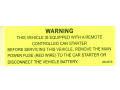
WARNING
THIS VEHICLE IS EQUIPPED WITH A REMOTE
CONTROLLED CAR STARTER
BEFORE SERVICING THIS VEHICLE, REMOVE THE MAIN
POWER FUSE (RED WIRE) TO THE CAR STARTER OR
DISCONNECT THE VEHICLE BATTERY.
LBL0675
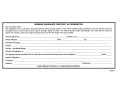
MAXIMUM INSURANCE DISCOUNT AUTHORIZATION
Dear Insurance Agent,
The installation of my Code-Alarm automatic (passive) arming security system in the vehicle indicated below qualifies me for the maximum discount
mandated by law in some states and by insurance company option in others. This vehicle security system automatically arms itself after the doors are
closed and includes at least one engine disabling relay to prevent the engine from being started.
Insured Signature:
Street Address:
Name(pleaseprinl):
State:
_
Zip:
InsuranceCompany:
_
_
Policy#:
_
Vehicle Year/Make/Model:
_
Vehicle Identification #:
_
The signature below certifies that my Code-Alarm automotive security system was installed on
(date)
Installer Signature:
_
_
Company:
_
Address:
Telephone:
_
PLEASE COMPLETE AND MAIL 10 YOUR INSURANCE COMPANY
1026673
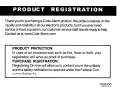
Register online at:
.CODE-AlARM.COM
Click On Product Registration
and Fill Out the Brief Questionnaire
Thank you for purchasing a Code-Alarm product. We pride ourselves on the
quality and reliability of all our electronic products, but if you ever need .
service or have a question, our customer service staff stands ready to help.
Contact us at www.Code-Alarm.com
PRODUCT PROTECTION:
In case of an insurance loss such as fire, flood or theft, your
registration will serve as proof of purchase.
PURCHASE REGISTRATION:
Registering On-Line will allow us to contact you in the unlikely
event a safety notification is required under the Federal Consumer Safety Act.
1026350
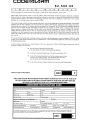
$2,500.00
L
I
M
I
T
E
w
D
A
R
R
A
N
y
T
CODE SYSTEMS, Inc makes the following warranty to YOU as the original purchaser of this system.
Should YOUR private passenger vehicle in which the CODE-ALARM ANTI-THEFT SYSTEM is originally installed by an authorized
dealer and while the system is operational and activated be stolen and not recovered or if stolen and recovered be deemed a total loss
for theft insurance purposes, then subject to the following conditions, YOU will be refunded the comprehensive auto insurance
deductible on your existing insurance not to exceed $2,500.00.
This Limited Warranty is effective for thefts occuning Within one (I) year from the original date of purchase providing that: (A) the attached
registration form has been completed in full and received by the CODE-ALARM Program Administrator at the address shown below
with postmark that is within five (5) business days from the original date of purchase; (B) YOU properly and completely identify the
vehicle in which the CODE-ALARM ANTI-THEFT SYSTEM has been installed; (C) YOUR vehicle is registered within the United
States of America or Canada; (D) the theft of YOUR vehicle occurs within the United States of America or Canada; (E) YOU file a
complete theft report with the police or other law enforcement agency having jurisdiction at the location of the theft; (F) YOU have
comprehensive or theft insurance in force on the vehicle at the time of the theft and YOU have filed a claim for the theft of the
vehicle with YOUR insurance canier; and (G) the theft claim with YOUR insurance carrier is settled and final payment from them has
been recei ved.
This Limited Warranty applied solely to passenger vehicles, motor homes, and light duty trucks or vans not =ceding 13,500 GVW. It does
not apply to any vehicle used in a business, for Livery or offered for hire. This Limited Warranty applies only to the vehicle as identified on
the attached registration form.
In order to make a claim under the Limited Warranty, YOU are to provide the CODE-ALARM Program Administrator with the
following information and materials:
•
Proof of purchase including the purchase date.
YOU ARE URGED TO SAVE YOUR ORIGINAL RECEIPT
•
A certified or notarized complete copy of the police report filed by YOU
•
A copy of the original declaration sheet from the insurance policy in force
at the time of the system purchase. This declaration sheet must clearly
show the amount of the deductible applicable to theft losses
•
A copy of the insurance company settlement check and any related documentation
I
CONTINUED ON REVERSE
c
ADV-
THIS CARD MUST BE POSTMARKED WITHIN THIRfY (30) BUSINESS DAYS OF THE PURCHASE
OF YOUR CODE-ALARM ANTI-THEFT SYSTEM ORIGINAL PURCHASE RECEIPf MUST BE
RETAINED AND SUBMITfED WITH ANY UAIMFlLED HEREUNDER
CONSUMER REGISTRATION CARD
Code-Alarm Anti-Theft System Purchased
Purchase Date
Name
Address
City
State
Zip
Vehicle Year
Make/Model
VIN
Insurance Carrier
Polic
Amount of Com rehensive or Theft Deductible
S
Dealer Name
Price Paid For S stem
Phone
Address
S
Was Inslallation Included? Yes
OPTIONAL lNFORMATION
Annual Household Income:
Purchased for:
Less than $20,000
c::::J
$20-40,000
c::::J
c::::J
Y Olll"self
No
c::::J
$40-60,000
c::::J
As a Gift
c::::J
c::::J
More than $60,000
c::::J
BY YOUR SIGNATURE BELOW, YOU (I) AGREE TO ALL OF THE TERMS AND CONDITIONS SET FORTH IN THIS LIMITED WARRANTY
AND (2) YOU UNDERSTAND AND AGREE THAT CODE SYSTEMS. Inc [S PROVID[NG YOU WITH A LIMITED WARRANTY AND THAT
THIS LIM [TED WARRANTY IS NOT AN INSURANCE POLICY.
ADVSignalure
Date
c
1026699
The CODE-ALARM Program Administrator reserves the right to ask for any other similar documentation or other materials
that may be reasonably required to verify YOUR claim. All documentation received on a claim becomes the Code-Alarm
Program Administrator's property and will not be returned.
All claim information must be mailed to the Code-Alarm Program Administrator within thirty (30) business days after receipt
of the final settlement check from YOUR insurance carrier.
For the protection of YOUR rights, YOU are urged to make copies of all materials submitted and to send all materials via registered
mail or any other means such that YOUR package can be traced in the event of its becoming lost or misdirected. The CodeAlarm Program Administrator is not responsible for materials not received in the CODE-ALARM Program Administrator's
office. Please allow four (4) to six (6) weeks to process any claim hereunder.
This limited warranty is not an insurance policy or insurance coverage and is contingent on the existence of and payment from an
underlying comprehensive auto insurance coverage and your compliance with all the terms and conditions set forth herein. This
limited warranty has no cash value and is subject to all the terms and conditions set forth within this document.
This warranty is in lieu of all other express warranties or liabilities. ANY IMPLIED WARRANTIES, INCLUDING ANY IMPLIED
WARRANTY OF MERCHANTABILITY, SHALL BE LIMITED TO THE DURATION OF THIS WRlTTEN WARRANTY, IN NO
CASE SHALL CODE-ALARM OR THE CODE-ALARM PROGRAM ADMINISTRATOR BE LIABLE FOR ANY CONSEQUENTIAL OR INCIDENTAL DAMAGES FOR BREACH OF THIS OR ANY OTHER WARRANTY, EXPRESSED OR
IMPLIED, WHATSOEVER. No person or representative is authorized to assume for the Company any liability other than
expressed herein in connection with the sale of this product.
Some states do not allow limitations on how long an implied warranty lasts or the exclusion or limitation of incidental or consequential
damage so the above limitations or exclusions may not apply to YOU. This warranty gives YOU specific legal rights and YOU may
also have other rights which vary from state to state.
THIS WARRANTY AND WARRANTY PROGRAM IS NOT AVAILABLE AND MA Y NOT BE
MARKETED IN OR FROM THE STATE OF FLORIDA.
THE CODE-ALARM PROGRAM ADMINISTRATOR
Post Office Box 231809
Encinitas, CA 92023
Phone (800) 7082113
POSTOFFlCE
WILL NOT
DELIVER
WITHOUT PROPER
POSTAGE AFFIXED
HERE
CODE-ALARM LIMITED WARRANTY PROGRAM
Post Office Box 231809
Encinitas, CA 92023