1
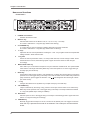
Analog Filter Module
WARNING!!
To reduce the risk of fire or electric shock, do not expose this apparatus to rain or moisture.
1-En
CAUTION
RISK OF ELECTRIC SHOCK
DO NOT OPEN
CAUTION: TO REDUCE THE RISK OF ELECTRIC SHOCK,
DO NOT REMOVE COVER (OR BACK).
NO USER-SERVICEABLE PARTS INSIDE.
REFER SERVICING TO QUALIFIED SERVICE PERSONNEL.
THE SYMBOLS ARE RULED BY UL STANDARDS (U.S.A.)
The lightning flash with arrowhead symbol , within an equilateral triangle, is intended to
alert the user to the presence of uninsulated “dangerous voltage” within the product’s
enclosure; that may be of sufficient magnitude to constitute a risk of electric shock to
persons.
The exclamation point within an equilateral triangle is intented to alert the user to the
presence of important operating and maintenance (servicing) instructions in the literature
accompanying the appliance.
5B-En
9/25/2001 Rev. 4
WARNING
WARNING: WHEN USING ELECTRIC PRODUCTS, BASIC PRECAUTIONS SHOULD ALWAYS
BE FOLLOWED, INCLUDING THE FOLLOWING:
WARNING
The MFC42 is designed to be used in a standard household environment.
Power requirements for electrical equipment differ from area to area. The operating voltage of this
MFC42 is preset at the factory according to its intended destination. However, before connecting,
check to see that the VOLTAGE SELECTOR on the rear panel is set to the correct voltage for your
area. If not, please set it correctly before plugging in the power cord. If in doubt, consult a qualified
electrician or AKAI professional dealer.
120 VAC
230 VAC
@ 60 Hz for USA and Canada
@ 50 Hz for Europe
If the VOLTAGE SELECTOR is not set correctly for your area:
Confirm that the power cord is disconnected.
Remove the VOLTAGE SELECTOR with a screw driver and
replace it so that the correct voltage for your area is lined with
the marker. Also, change the fuse according to the chart
indicated on the rear panel as necessary.
PROTECTING YOURSELF AND THE MFC42
• Never touch the AC plug with wet hands.
• Always disconnect the MFC42 from the power supply
by pulling on the plug, not the cord.
• Allow only an AKAI professional dealer or qualified professional engineer to repair or reassemble
the MFC42. Apart from voiding the warranty, unauthorized engineers might touch live internal
parts and receive a serious electrical shock. There are no serviceable parts inside.
• Do not put, or allow anyone to put any object, especially metal objects, into the MFC42.
• Use only a household AC power supply. Never use a DC power supply.
• If water or any other liquid is spilled into or onto the MFC42, disconnect the power, and call your
dealer.
• Make sure that the unit is well-ventilated, and away from direct sunlight.
• To avoid damage to internal circuitry, as well as the external finish, keep the MFC42 away from
sources of direct heat (stoves, radiators, etc.).
• Avoid using aerosol insecticides, etc. near the MFC42. They may damage the surface, and
may ignite.
• Do not use denatured alcohol, thinner or similar chemicals to clean the MFC42. They will damage
the finish.
• Modification of this equipment is dangerous, and can result in the functions of the MFC42 being
impaired. Never attempt to modify the equipment in any way.
• Make sure that the MFC42 is always well-supported when in use (either in a specially-designed
equipment rack, or on a firm level surface).
• When installing the MFC42 in a 19” rack system, always allow 1U of ventilated free space
above it to allow for cooling. Make sure that the back of the rack is unobstructed to allow a clear
airflow.
• In order to assure optimum performance of your MFC42, select the setup location carefully,
and make sure the equipment is used properly. Avoid setting up the MFC42 in the following
locations:
1. In a humid or dusty environment
2. In a room with poor ventilation
3. On a surface which is not horizontal
4. Inside a vehicle such as a car, where it will be subject to vibration
5. In an extremely hot or cold environment
i
WARNING
For U.K. Customers Only
WARNING
THIS APPARATUS MUST BE EARTHED
IMPORTANT
This equipment is fitted with an approved non-rewireable UK mains plug.
To change the fuse in this type of plug proceed as follows:
1) Remove the fuse cover and old fuse.
2) Fit a new fuse which should be a BS1362 5 Amp A.S.T.A or BSI approved type.
3) Refit the fuse cover.
If the AC mains plug fitted to the lead supplied with this equipment is not suitable for your type of
AC outlet sockets, it should be changed to an AC mains lead, complete with moulded plug, to the
appropriate type. If this is not possible, the plug should be cut off and a correct one fitted to suit the
AC outlet. This should be fused at 5 Amps.
If a plug without a fuse is used, the fuse at the distribution board should NOT BE GREATER than
5 Amp.
PLEASE NOTE:
THE SEVERED PLUG MUST BE DESTROYED TO AVOID A POSSIBLE
SHOCK HAZARD SHOULD IT BE INSERTED INTO A 13 AMP SOCKET
ELSEWHERE.
The wires in this mains lead are coloured in accordance with the following code:
GREEN and YELLOW
— Earth
BLUE
— Neutral
BROWN
— Live
As the colours of the wires in the mains lead of this apparatus may not correspond with the coloured
markings identifying the terminals in your plug, please proceed as follows:
The wire which is coloured GREEN and YELLOW must be connected to the terminal which is
marked with the letter E or with the safety earth symbol
or coloured GREEN or coloured
GREEN and YELLOW.
The wire which is coloured BLUE must be connected to the terminal which is marked with the
letter N or coloured BLACK.
The wire which is coloured BROWN must be connected to the terminal which is marked
with the etter L or coloured RED.
THIS APPARATUS MUST BE EARTHED
Ensure that all the terminals are securely tightened and no loose strands of wire exist.
Before replacing the plug cover, make certain the cord grip is clamped over the outer sheath of the
lead and not simply over the wires.
6D-En
ii
WARNING
FCC WARNING
This equipment has been tested and found to comply with the limits for a Class B digital device
pursuant to Part 15 of the FCC rules. These limits are designed to provide reasonable protection
against harmful interference in a residential installation. This equipment generates, uses, and
can radiate radio frequency energy and, if not installed and used in accordance with the
instructions, may cause harmful interference to radio communications. However, there is no
guarantee that interference will not occur in a particular installation. If this equipment does
cause harmful interference to radio or television reception, which can be determined by turning
the equipment off and on, the user is encouraged to try to correct the interference by one or
more of the following measures:
•
Reorient or relocate the receiving antenna.
•
Increase the separation between the equipment and receiver.
•
Connect the equipment into an outlet on a circuit different from that to which the receiver is
connected.
•
Consult the dealer or an experienced radio/TV technician for help.
21B-En
AVIS POUR LES ACHETEURS CANADIENS DU MFC42
Le présent appareil numérique n’ément pas de bruits radioélectriques dépassant les limites
applicables aux appareils numériques de la Class B prescrites dans le Règlement sur le
brouillage radioélectrique édicté par le ministère des Communications du Canada.
27-F
This digital apparatus does not exceed the Class B limits for radio noise emissions from digital
apparatus set out in the Radio Interference Regulations of the Canadian Department of
Communications.
27-En
VENTILATION
Do not prevent the unit’s ventilation, especially by placing the unit on the soft carpet, in a
narrow space, or by placing objects on the unit’s chassis—top, side, or rear panels. Always
keep the unit’s chassis at least 10 centimeters from any other objects.
31C-En
CHANGES OR MODIFICATIONS NOT EXPRESSLY APPROVED BY THE MANUFACTURER
FOR COMPLIANCE COULD VOID THE USER’S AUTHORITY TO OPERATE THE
EQUIPMENT.
32-En
COPYRIGHT NOTICE
The AKAI MFC42 contains and uses software in ROMs. This software, and all related
documentation, including this OperatorOs Manual, contain proprietary information which is
protected by copyright laws. All rights are reserved. No part of the software or its documentation
may be copied, transferred or modified. You may not modify, adapt, translate, lease, distribute,
resell for profit or create derivative works based on the software and its related documentation or
any part thereof without prior written consent from AKAI professional M.I. Corp., Yokohama,
Japan.
iii
WARNING
WARRANTY
AKAI professional M.I. Corp. warrants its products, when purchased from an authorized “AKAI professional”
dealer, to be free from defects in materials and workmanship for a period of 12 (twelve) months from the date
of purchase. Warranty service is effective and available to the original purchase only, and only on completion
and return of the AKAI professional Warranty Registration Card within 14 days of purchase.
Warranty coverage is valid for factory-authorized updates to AKAI professional instruments and their software,
when their installation is performed by an authorized AKAI professional Service Center, and a properly
completed Warranty Registration has been returned to your “AKAI professional” dealer.
To obtain service under this warranty, the product must, on discovery of the detect, be properly packed and
shipped to the nearest AKAI professional Service Center. The party requesting warranty service must provide
proof of original ownership and date of purchase of the product.
If the warranty is valid, AKAI professional will, without charge for parts or labor, either repair or replace the
defective part(s). Without a valid warranty, the entire cost of the repair (parts and labor) is the responsibility of
the product’s owner.
AKAI professional warrants that it will make all necessary adjustments, repairs and replacements at no cost
to the original owner within 12 (twelve) months of the purchase date if:
1)
The product fails to perform its specified functions due to failure of one or more of its components.
2)
The product fails to perform its specified functions due to defects in workmanship.
3)
The product has been maintained and operated by the owner in strict accordance with the written
instructions for proper maintenance and use as specified in this Operator’s Manual.
Before purchase and use, owners should determine the suitability of the product for their intended use, and
owner assumes all risk and liability whatsoever in connection therewith. AKAI professional shall not be liable
for any injury, loss or damage, direct or consequential, arising out of use, or inability to use the product.
The warranty provides only those benefits specified, and does not cover defects or repairs needed as a result
of acts beyond the control of AKAI professional, including but not limited to:
1)
Damage caused by abuse, accident, negligence. AKAI professional will not cover under warranty any
original factory disk damaged or destroyed as a result of the owner’s mishandling.
2)
Damage caused by any tampering, alteration or modification of the product: operating software,
mechanical or electronic components.
3)
Damage caused by failure to maintain and operate the product in strict accordance with the written
instructions for proper maintenance and use as specified in this Operator’s Manual.
4)
Damage caused by repairs or attempted repairs by unauthorized persons.
5)
Damage caused by fire, smoke, falling objects, water or other liquids, or natural events such as rain,
floods, earthquakes, lightning, tornadoes, storms, etc.
6)
Damage caused by operation on improper voltages.
IMPORTANT NOTE:
This warranty becomes void if the product or its software is
electronically modified, altered or tampered with in any way.
AKAI professional shall not be liable for costs involved in packing or preparing the product for shipping, with
regard to time, labor, or materials, shipping or freight costs, or time or expense involved in transporting the
product to and from AKAI professional Authorized Service Center or Authorized Dealer.
AKAI professional will not cover under warranty an apparent malfunction that is determined to be user error,
or owner’s inability to use the product.
THE DURATION OF ANY OTHER WARRANTIES, WHETHER IMPLIED OR EXPRESS, INCLUDING BUT
NOT LIMITED TO THE IMPLIED CONDITION OF MERCHANTABILITY, IS LIMITED TO THE DURATION
OF THE EXPRESS WARRANTY HEREIN.
AKAI professional hereby excludes incidental or consequential damages, including but not limited to:
1) Loss of time.
iv
2)
Inconvenience
3)
Delay in performance of the Warranty.
4)
The loss of use of the product.
5)
Commercial loss.
6)
Breach of any express or implied warranty, including the Implied Warranty of Merchant-ability, applicable
to this product
WARNING
v
CONTENTS
CONTENTS
Chapter 1 Introduction ....................................................................................................
Features ..................................................................................................................
Names and functions ...............................................................................................
Front Panel .........................................................................................................
Rear Panel .........................................................................................................
1
1
2
2
5
Chapter 2 Basic Operation ..............................................................................................
Connections .............................................................................................................
Signal flow ...............................................................................................................
Keywords in basic operation ...................................................................................
Filter operation .........................................................................................................
Changing the sound ................................................................................................
6
6
6
7
8
9
Chapter 3 Advanced Operations .................................................................................. 10
Keywords in advanced operation .......................................................................... 10
Groove Modulator ................................................................................................... 11
Control the cut-off cyclically with Groove Modulator (TAP TEMPO) ...................... 12
Control the cut-off cyclically with Groove Modulator (RATE) ................................. 14
Control the cut-off cyclically with Groove Modulator (MIDI CLOCK SYNC) .......... 14
Shifting LFO waveform with L-R PHASE ............................................................... 15
Control on Mono channel with Groove Modulator ................................................. 15
MANUAL TRIGGER .............................................................................................. 16
Controlling Cut-off on Mono and Stereo channels simultaneously ........................ 16
Chapter 4 MIDI Function ...............................................................................................
MIDI Receive channel setting ................................................................................
Recording the knob operation to sequencer ..........................................................
Sending the settings via MIDI ................................................................................
18
18
18
19
Chapter 5 Connections to Others ................................................................................
Connecting to Keyboard as external Filter Module ................................................
Connecting the Turntable .....................................................................................
Connecting MPC2000/MPC2000XL ......................................................................
Connecting MPC3000 ...........................................................................................
20
20
20
20
23
Specifications ................................................................................................................ 24
vi
Chapter 1 Introduction
Chapter 1 Introduction
Thank you very much for your purchase of the MFC42. Here, you see its unique features and functions
explained.
Features
Four 2-pole Analog Filters
By the combination of four 2-pole filters, the MFC42 can be configured as 8-pole filter unit maximum. The
sharp cut-off curve and powerful resonance setting allow wide range of sound making possible.
Stereo and Mono Input
Equipped with the Stereo Input and Mono Input independently and can be controlled separately. For
instance, swing the rhythm section from Stereo Input with LFO while the bass from Mono Input being
radically changed by manual filter settings – works as two conventional filter units.
Four Filter types
The four filter settings of High pass, Low pass, Band pass and Notch. The filter type can be switched
directly by the combination of toggle switch settings.
Groove Modulator
The Groove Modulator function offers the control of filter cut-off or resonance synced to the rhythm. By the
combination of Tap Tempo or MIDI Clock Sync functions with LFO/Envelope, the filter cut-off/resonance
can be controlled. It also has the Manual Trigger function to trigger the envelope manually at any point.
MIDI function
Almost all keys and knobs are assigned with the MIDI Control Change number. With the use of external
sequencer, e.g. MPC2000/MPC2000XL, the movement of each key and knob can be recorded and played
back later. The Send Scene function can send all the key and knob settings at once via MIDI. By recording
this data at the beginning of each sequence, the settings can later be recalled when played back.
Analog Phaser/Distortion
The Phase Shifter and Distortion effects are built-in. The addition of these effects to the filter control makes
the sound control more flexible.
2-Band EQ on Output
With the High and Low EQ at the output stage, the tone of output sound can be controlled.
Phono Input
With the Phono Input provided at Stereo Input with LINE/PHONO selector, the turntable can be connected
directly.
2U Rack mountable
The enclosure is shaped so that it can either be rack mounted or placed on desktop to suit your playing
style. With the optional mounting kit, i.e. KIT-MFC, the MFC42 can be mounted on the MPC2000/
MPC2000XL.
1
Chapter 1 Introduction
Names and functions
– Front Panel –
1.
POWER switch button
Switches the MFC42 on/off.
2.
MIDI CH. key
Sets the MIDI channel of the MFC42. Off, 01~16, L01~L16 (L: Local Off)
3.
The value is indicated on 7-seg LED (key flickers while setting).
CC NUMBER key
To confirm the CC (Control Change) numbers assigned to the keys and knobs.
The value is indicated on 7-seg LED (key flickers while confirming).
4.
5.
+/– keys
Adjust the value of various parameters. Pressing the + and – keys together sends out all parameter
settings via MIDI – Send Scene function.
7-seg LED
Shows the various parameter values, i.e. Tempo, MIDI channel, Control Change number. When
the RATE knob is moved, the flickering speed of upper and lower halves of LED changes
6.
accordingly.
MIDI CLOCK SYNC key
Set to ON to sync to the external sequencer or rhythm machine via MIDI Clock. The speed of MIDI
Clock and the note length selected by BEAT key control the speed of LFO or the trigger timing of
7.
envelope (key is lit while ON).
BEAT key
Used with the MIDI CLOCK SYNC or TAP TEMPO key, it selects the note length that controls the
speed of LFO or the trigger timing of envelope. One of the six LEDs on their side is always selected
(ON) and the key press toggles the selection. The
(two whole notes).
mark designates the note length of breve
8.
- 3 - key
Changes the selected note by BEAT key to triplet notes (key is lit while ON).
9.
TAP TEMPO key
Tempo is detected by the timing of key presses. The tempo entered and the note selected by
BEAT key set the speed of LFO or the trigger timing of envelope. The tempo entered is indicated
on 7-seg LED (default tempo setting is 120BPM).
10. RATE knob
Sets the speed of LFO or the trigger timing of envelope. The flickering speed of upper and lower
halves of 7-seg LED changes accordingly.
11. TRIGGER key
Manually triggers the envelope for cut-off or resonance at desired point. The trigger is turned on
when the key is pressed and turned off as released. The envelope is set with A/D/S/R
knobs.
2
Chapter 1 Introduction
12. A knob
Sets the attack time of envelope.
13. D knob
Sets the decay time of envelope.
14. S knob
Sets the sustain level of envelope.
15. R knob
Sets the release time of envelope.
16. ENVELOPE key
The BEAT Module triggers the envelope for cut-off/resonance cyclically when it’s ON (key is lit
while ON).
17. LFO key
The BEAT Module applies the LFO of constant speed to cut-off/resonance when it’s ON (key is
lit while ON).
18. WAVE key
Selects the waveform for LFO from 4 waveforms of Triangle, Square, Sawtooth and Random. The
key press toggles the waveform selected. The LED of selected waveform is lit.
19. CUTOFF key
The cut-off is controlled by the Groove Modulator or Manual Trigger when ON (LED is lit while
ON). It can be used with RESO key.
20. RESO key
The resonance is controlled by the Groove Modulator or Manual Trigger when ON (LED is lit while
ON). It can be used with the CUTOFF key.
21. DEPTH knob
Sets the depth of LFO waveform/amount of envelope change that controls cut-off/resonance.
The larger the LFO waveform/Envelope, the more the changes.
22. DESTINATION switch
Selects the destination of Groove Modulator/Manual Trigger to either Mono or Stereo channel to
control its cut-off/resonance.
23. L-R PHASE knob
Adjusts the phase difference of LFO waveform between Left and Right channels (Stereo channel
only).
24. INPUT knobs (Mono/Stereo channels)
Adjusts the input level. This adjusts the signal level introduced to the filter module.
25. 2 POLE keys (Mono/Stereo channels)
Turns 2-pole filter on/off (key is lit while ON).
26. 4 POLE keys (Mono/Stereo channels)
Turns 4-pole filter on/off (key is lit while ON).
28. FILTER TYPE switches (Mono/Stereo channels)
Selects the filter type from High pass, Low pass, Band pass and Notch type (
and
4
27. 8 POLE key (Mono channel only)
Turns 8-pole filter on/off (key is lit while ON).
designates up
designates down position).
29. CUTOFF knobs (Mono/Stereo channels)
Adjusts the cut-off frequency of filter. The sound changes with the rotation of knob.
30. RESONANCE knobs (Mono/Stereo channels)
Adjusts the resonance of filter. Gives sound the distinguishable character. It even oscillates when
the knob is turned up too high.
3
Chapter 1 Introduction
31. LEVEL knobs (Mono/Stereo channels)
Adjusts the output level of filter module. These are used to balance the Mono/Stereo outputs.
32. LINK key
Enables to control the cut-off for both Mono and Stereo channels simultaneously. The CUTOFF
knob on Mono channel controls both channels.
The CUTOFF knob on Stereo channel is disabled when LINK is ON (LED is lit while ON).
33. INVERT key
Inverts the movement of cut-off control for Mono and Stereo channels only while LINK is ena
bled (LED is lit while ON).
34. PAN knob (Mono channel only)
Adjusts the panning of output signal from the Mono channel filter module.
35. PHASE SHIFTER key
Turns the phase shifter effect on/off. It gives sound the swirl effect/rolling effect (LED is lit while
ON). The effect is applied to both Mono and Stereo channels.
36. SPEED knob (Phase Shifter)
Adjusts the speed of phase shifter (swirling/rolling) effect.
37. DEPTH knob (Phase Shifter)
Adjusts the depth/amount of phase shifter (swirling/rolling) effect.
38. DISTORTION key
Turns the distortion effect on/off. It distorts the sound (LED is lit while ON). The effect is applied
to both Mono and Stereo channels.
The amount of distortion is adjusted by the INPUT and/or LEVEL knobs on Mono/Stereo channels.
The output level is adjusted by the OUTPUT knob.
39. OUTPUT knob (Distortion)
Adjusts the OUTPUT level of distortion effect.
40. HIGH knob (EQ)
Adjusts the level of high frequency component in OUTPUT L/R and headphones.
41. LOW knob (EQ)
Adjusts the level of low frequency component in OUTPUT L/R and headphones.
42. MAIN VOLUME knob
Adjusts the level of OUTPUT L/R.
43. PHONES LEVEL knob
Adjusts the level of headphones.
4
Chapter 1 Introduction
– Rear Panel –
`
†
@ · d
Œ
Æ
‰ Œ
d ˝
h ~
A L
r l b g ˝ J fl ¨ ¢ ¯ ” ‡ ¢ B
˝ ¤
¢ ª
¢ ‰
¢ ‰
X
C
† ¸
” ‡ ¢ B
1.
MONO IN
2.
Input phone jack for the Mono channel.
STEREO IN
Two types of input connectors for the Stereo channels, 2 phone jacks and 2 RCA connectors.
Both types of connectors can be used simultaneously (but without their balance control). When
3.
Mono signal is used, connect it to L/MONO phone jack.
LINE/PHONO switch
4.
Set the slide switch to PHONO side when the turntable is used.
SIGNAL GND terminal
5.
Used for the signal grounding of the turntable.
OUTPUT L/R
Two types of output connectors for the output L/R, 2 phone jacks and 2 RCA connectors. Both
types of connectors can be used simultaneously. The same signal is available on both.
6.
MIDI IN
Receives the MIDI signal.
7.
MIDI OUT
Sends out the MIDI signal.
8.
MIDI THRU
Returns the MIDI signal received at MIDI IN terminal.
9.
AC Inlet
Connects the power cord supplied.
Note: This unit is equipped with the voltage selector. Be sure to check the setting, before
connection.
5
Chapter 2 Basic Operation
Chapter 2 Basic Operation
Connections
Be sure to turn all equipment off before making connections.
`
†
@ · d
Œ
Æ
‰ Œ
d ˝
h ~
A L
r l b g ˝ J fl ¨ ¢ ¯ ” ‡ ¢ B
˝ ¤
¢ ª
¢ ‰
¢ ‰
X
C
† ¸
” ‡ ¢ B
SIGNAL
GND
PHONO
MIDI OUT
MIDI IN
MONO OUT
Sequencer
Sequencer
Synthesizer
Turntable
Monitor
STEREO(L/R)
Rhythm machine
Signal flow
MONO
INPUT LEVEL
FILTER
PAN
LEVEL
OUTPUT L/R
PHASER
DIST
EQ
STEREO
INPUT LEVEL
6
FILTER
LEVEL
PHONES
Chapter 2 Basic Operation
Keywords in basic operation
[Filter]
As the coffee filter, it separates one to pass through
and the other to block. In sound application, the
Level
separation is determined by their signal frequencies.
This particular criterion frequency is called as “cut-off
frequency”. There are several filter types of different
characteristics.
Low
Frequency
High
Frequency response in original
passes through filter ···
Cutoff frequency
Level
Low
Frequency
Level
High
Cutoff frequency
Low
HIGH PASS
Frequency
High
LOW PASS
<HIGH PASS>
Passes the frequency components higher than the
cut-off frequency and cuts out the lower frequency
components.
<LOW PASS>
Passes the frequency components lower than the cut-off
frequency and cuts out the higher frequency components.
Level
Level
Cutoff frequency
Low
Frequency
High
BAND PASS
Cutoff frequency
Low
Frequency
High
NOTCH
<BAND PASS>
Passes the frequency components adjacent to the
<NOTCH>
Cuts out the frequency components adjacent to the cut-off
cut-off frequency and cuts out the higher and lower
frequency components.
frequency and passes through the higher and lower
frequency components.
Note: The CUTOFF knob may not change the sound
character as the depth of filter notch is lessened when
RESONANCE knob is turned up.
[Cut-off]
The point specified in frequency that determines where the filter effect takes place. The filter separates the
signal, to pass or cut-out, referenced to the cut-off frequency. Changing the cut-off frequency changes the
sound character.
[Resonance]
It accentuates the frequency components near the cut-off frequency to give sound the distinguish
character. It oscillates when it’s overdone.
7
Chapter 2 Basic Operation
RESONANCE knob fully counter-clockwised position
Level
Cutoff frequency
Level
As the knob is turned up . . .
Low
Frequency
High
Low
Frequency
High
[Pole]
2POLE (-12dB/oct)
4POLE (-24dB/oct)
8POLE (-48dB/oct)
Determines the shape of cut-off curve. The larger
the number, the sharper the curve. The sound
character is different with different curves.
(1 pole = -6dB/Octave)
Note: Up to 8-pole is available on Mono channel.
Filter operation
Frequency
Cutoff frequency
(-3dB)
Let’s master the operation of MFC42, confirming how the sound changes when the signal goes through
the filter, in the actual application.
The following is based on the connection of rhythm machine (stereo connection), but the operation of the
MFC42 is the same with other devices.
<Preparation>
(Connection to rhythm machine)
Connect the stereo output of the rhythm machine to the STEREO IN connectors of the MFC42. Connect
the OUTPUT L/R to your sound monitor system (or connect your headphones to the headphone jack,
instead).
While the MAIN VOLUME is turned down, turn on the rhythm machine, the MFC42 and then your monitor
system in that order.
(Level adjust)
Adjust the level of MFC42 while playing
the rhythm machine. Turn the INPUT and
LEVEL knobs on Stereo channel fully
clockwise. Next, turn the MAIN VOLUME
(or PHONES LEVEL for headphone) up
to the appropriate level.
(Panel settings)
Turn the RESONANCE fully counterclockwise and the CUTOFF knob to 2
O’clock position, and set the FILTER
TYPE switches to LOW PASS (both switches down) position.
Now, we’re all set to experiment.
(Auto-tuning)
As the characteristic of analog circuitry, the heat makes the filter cut-off operation unstable. With the
built-in Auto-tuning function, it self-adjusts the internal filter circuit optimal.
• Press the MIDI CH. and CC NUMBER keys simultaneously to start it (bars on LED flash while autotuning). Perform this auto-tuning when the unit is warmed up.
8
Chapter 2 Basic Operation
Changing the sound
1.
Passing the filter
First, pass the input signal through the filter on the Stereo channel.
Press 2 POLE key on the Stereo channel. This makes the sound of rhythm machine go through the
filter. You now hear the change in sound already.
2.
CUTOFF change
The CUTOFF knob changes the character of sound fed through the filter.
Try rotating the CUTOFF knob, paying attention to the character of sound. Now press 4 POLE and 2
POLE keys alternatively while rotating the CUTOFF knob to hear the difference by the number of
poles.
3.
FILTER TYPE selection
FILTER TYPE, as the name implies, the type of filters is selected here by the combination of toggle
switch position.
Depending on the filter type selected by the combination of these switches, the way the sound change
differs when the CUTOFF knob is rotated. Try selecting the different filter types while rotating the
CUTOFF knob. Also, try them out with different pole selections. (Refer to Keywords in basic
operation.)
4.
RESONANCE change
The resonance effect gives the distinguish character of metallic sound.
Try rotating the RESONANCE knob. It should sound metallic as you rotate the knob. As the effect of
RESONANCE changes largely on the position of CUTOFF knob, try changing the CUTOFF position
when the effect of resonance is not so significant.
5.
Using the effects
The MFC42 has the Phase Shifter and Distortion effects unit built-in.
The phase shifter gives the sound the swirl or roll effect. The distortion effect distorts the sound.
Turn the PHASE SHIFTER on and adjust the SPEED and DEPTH knobs. Hear how the sound
changes with the various CUTOFF and FILTER TYPE settings. Turn the DISTORTION on and check
its effect, also. The output level of distortion is adjusted by the OUTPUT knob. The amount of
distortion is adjusted by the INPUT and/or LEVEL knobs on Mono/Stereo channele. These two effects
can be used simultaneously.
6.
Adjusting the EQ
The MFC42 is equipped with the 2-band EQ. Adjust the tone of sound to your taste with the HIGH/
LOW knobs.
The operation on Stereo channel has been explained above. The operation on Mono channel is basically
the same with the following few exceptions.
• The PAN knob is available for panning adjustment.
• The selection of up to 8 POLE is available.
9
Chapter 3 Advanced Operations
Chapter 3 Advanced Operations
Keywords in advanced operation
[LFO]
The LFO stands for the Low Frequency Oscillator. The LFO waveform is used to control the pitch, level and
character of sound cyclically.
In the MFC42, the LFO is applied to the cut-off/resonance to change the character of sound cyclically. Also,
the waveform of LFO changes the way it changes the sound character.
Applying LFO to Cutoff/Resonance . . .
Slow
In Cutoff
L
F
O
s
p
e
e
d
LFO waveform
apply this to cutoff . . .
1 cycle
Frequency
LFO OFF
1 cycle
Cutoff frequency
Fast
1 cycle
Time
LFO ON
The LFO speed means the length
of waveform.
The cutoff frequency changes along the LFO waveform.
[Envelope]
It’s the parameter that changes the pitch, level and
character of sound in time span.
In the MFC42, it is applied to the cut-off/resonance
to change the sound in time.
Adjusting trigger timing of Envelope . . .
The A/D/S/R knobs adjust the shape of envelope.
Slow
Applying Envelope to Cutoff/Resonance . . .
Trigger timing of Envelope
Trigger
timing
In Cutoff
When Envelope of this
ADSR setting is triggered . . .
Fast
Frequency
Note OFF
Cutoff frequency
Time
Note ON
10
In Envelope, it adjusts the duration between Envelopes, not like the cycle length in LFO. The ADSR
knobs adjust the shape of Envelope. When Envelopes overlap as the duration is set too short, the
following envelope resets the previous one.
When Envelope is triggered by the Groove Modulator described later, the shape of Envelope becomes as shown above since the sustain time is
zero. Refer also to [ADSR] on next page.
Chapter 3 Advanced Operations
[ADSR]
The ADSR stands for the Attack
Changes
time, Decay time, Sustain level and
Release time of the envelope. In the
Note OFF
example of keyboard instrument,
the Attack time is the time between
the key press and the time it takes
to reach the maximum sound level.
Sustain level
(S)
The Decay time is the time it takes
to reach reach to the sustain level
Attack time Decay time
(A)
(D)
from the maximum level. The
Sustain level is the level while the
Release time
(R)
Time
Note ON
key is held pressed. The Release time is the time between the key is released and the sound diminished.
As in the above example, the envelope is often used change the sound level in time span. In the MFC42,
the ADSR envelope is applied to the cut-off/resonance to change the sound character in time span.
Note: When the envelope is triggered by the Groove Modulator, described later, the envelope becomes as
the waveform shown at “Adjusting the trigger timing of envelope” on the previous page since the sustain
time (the time the key is held) is not programmable. Similarly, in the Manual Trigger operation, the sustain
time is the time the TRIGGER key being held.
Groove Modulator
What is the Groove Modulator?
In order to control the cut-off and/or resonance and change the sound character cyclically, it requires the
setting of “speed”, “way” and “amount” of change. The section that does all these is called the Groove
Modulator and consists of the BEAT module, LFO/ENVELOPE module and DEPTH module.
GROOVE MODULATOR
BEAT MODULE
MIDI/TAP/RATE
(Speed of change)
CUTOFF
LFO/ENVELOPE
(Way of change)
RESONANCE
DEPTH
(Amount of change)
BEAT module (speed of change)
This is the module that sets the speed of LFO and the trigger timing of envelope. It consists of MIDI CLOCK
SYNC, TAP TEMPO and RATE modules. One of them is selected to control the speed and timing.
LFO/ENVELOPE (way of change)
This module sets the way the cut-off/resonance is changed. The sound is changed according to the shape
of LFO/Envelope specified (either one of LFO or Envelope is selectable, but not both).
DEPTH (amount of change)
This module sets the magnitude of LFO waveform or the depth of envelope. The magnitude of waveform
or the depth corresponds to the amount of change.
11
Chapter 3 Advanced Operations
Control the cut-off cyclically with Groove Modulator (TAP TEMPO)
Cut-off control with LFO
We’re going to explain how to control the cut-off by the Groove Modulator with the rhythm machine
connected (stereo connection). Follow the steps below while playing back the rhythm machine.
Preparation
Turn on the LFO, CUTOFF and 2 POLE
(Stereo channel) keys. Set the FILTER
ON
TYPE as LOW PASS and set the
CUTOFF and RESONANCE knobs to 12
O’clock position. Be sure to set the
DESTINATION switch to Stereo channel
(down position).
ON
ON
Procedure
1. LFO speed setting (speed of change)
Set the LFO speed with TAP TEMPO and BEAT keys.
Press the TAP TEMPO key twice in sync to the rhythm
(default tempo setting is 120BPM). The fine
adjustment of tempo can be made with +/– keys.
Select the note pressing the BEAT key. Pressing the
BEAT key toggles the note selected. Select the
crotchet note for the time being (it can be changed
Tempo entry
Press the key twice.
The tempo is calculated by the time between the
first key press and the next.
The tempo entered is shown on the 7-seg LED.
later). The length of this note is the length (1 cycle) of the LFO waveform. (Refer to the Keyword in
advanced operation.)
2. LFO waveform selection (way of change)
Selects the LFO waveform here to specify how the cut-off changes.
Press WAVE key to select the waveform. The key press toggles the waveform selection. Select the
“Triangle” for this example.
3. LFO magnitude setting (amount of change)
Rotate the DEPTH knob to adjust the
+
In LFO
magnitude of LFO waveform. The sound
begins to change as the DEPTH knob is
rotated to + (or –) side. For easier
understanding of sound change, turn the knob
Knob
position
Cutoff frequency
(DEPTH knob 0)
0
fully clockwise here.
Note: When the DEPTH is set at 0, no change
is observed as the magnitude of waveform is
set to zero.
–
By this step, the sound is changed cyclically synced to the rhythm.
12
Chapter 3 Advanced Operations
In this set up, try changing the note length with the BEAT key or changing the LFO waveform with WAVE
key. The way the sound changes is altered while still synced to the rhythm.
Further, the rotation of CUTOFF and RESONANCE knobs and/or the selection of FILTER TYPE and the
number of poles change the sound as well.
The - 3 - key changes the selected note by the BEAT key to triplets.
Cut-off control with Envelope
Now, we’ll use the Envelope instead of LFO. The overall steps are similar to those of LFO.
Preparation
Turn on the ENVELOPE, instead of LFO. Other settings are the same as those for LFO.
Procedure
1. Envelope trigger timing (speed of change)
Set the Envelope trigger timing with TAP TEMPO and BEAT keys.
The TEMPO and BEAT settings are the same as those for LFO.
For the Envelope, it only sets the timing of the envelope, but not the length as in the case of LFO.
The A/D/S/R knobs adjust the shape of envelope (Refer to Keywords in advanced operation).
Select the crotchet note for the time being (it can be changed later).
2. Envelope setting (way of change)
As for the LFO, the Envelope can specify how the cut-off/resonance changes. However, since the
envelope has no preset shape as the LFO waveform, it is required to set how to change manually.
The A/D/S/R knobs set the envelope shape. Set the A/D knobs to 11 O’clock and the S/R knobs to 12
O’clock position, for example.
3. Envelope depth (amount of change)
Rotate the DEPTH knob to adjust the amount
of change.
+
In Envelope
The sound begins to change as the DEPTH
knob is rotated to + (or -) side. For easier
understanding of sound change, turn the knob
fully clockwise here.
Knob
position
Cutoff frequency
(DEPTH knob 0)
0
Note: When the DEPTH is set at 0, no change
is observed as the amount of change is set to
zero.
–
Similar to the LFO, try changing the trigger
timing with the BEAT key or changing the envelope with A/D/S/R knobs. The way the sound changes
is altered while still synced to the rhythm.
Further, the rotation of CUTOFF and RESONANCE knobs and/or the selection of FILTER TYPE and
the number of poles change the sound as well.
The - 3 - key changes the selected note by the BEAT key to triplets.
13
Chapter 3 Advanced Operations
Up to this point, we explained how to control the cut-off using the LFO or Envelope. The same procedure
can be applied to control the resonance by pressing the RESO key, instead of the CUTOFF key.
When you want to control both the cut-off and resonance, turn both the CUTOFF and RESONANCE
keys ON.
Note: When both cut-off and resonance are controlled, it may sound as if the resonance is not changed
since the cut-off effect is more dominant.
Control the cut-off cyclically with Groove Modulator (RATE)
Preparation
The same as those used for the TAP TEMPO settings apply.
Procedure
1. LFO speed setting
The RATE knob sets the speed of LFO without the settings of tempo and/or note length. Now, try
rotating the RATE knob. The tempo is not displayed on the LED, but the flickering speed of upper and
lower halves of LEDs changes by the RATE knob setting.
The rest of the procedure for the LFO waveform selection and its magnitude adjustment is the same
for the TAP TEMPO settings (refer to page 12).
The procedure to use the Envelope, instead of LFO, is similar.
Difference
• Press the ENVELOPE key, instead of the LFO key.
•
•
The RATE knob sets the trigger timing of Envelope, instead of LFO speed.
The A/D/S/R knobs set the shape of Envelope, instead of waveform selection with the WAVE key.
Rotate the CUTOFF and RESONANCE knobs and/or change the selection of FILTER TYPE and the
number of poles to confirm the change of sound.
Control the cut-off cyclically with Groove Modulator (MIDI CLOCK SYNC)
With the connection of external MIDI device such as the rhythm machine and sequencer, you can control
the cut-off/resonance in sync to the MIDI clock.
Preparation
First, you need to connect the external MIDI device that can send out the MIDI clock to the MFC42 via the
appropriate MIDI cable (Refer to the operator’s manual of the external MIDI device how to send the MIDI
clock out.). The rest of the settings are the same as those used for the TAP TEMPO settings.
Procedure
1. LFO speed/Envelope trigger timing setting (speed of change)
Set the LFO speed with MIDI CLOCK SYNC and BEAT keys.
Turn the MIDI CLOCK SYNC key on. The MFC42 is ready to receive the MIDI clock. When the MIDI
clock is received properly from the external MIDI device, the “Syn” is displayed on the 7-seg LED. The
“no” and “Syn” is displayed alternatively on the 7-seg LED when the MIDI clock is not received properly.
Select the note length with the BEAT key and which sets the LFO speed.
Note: When the MIDI clock is not received properly, the last used clock rate memorized is used (while
the unit is on). The default value of 120BPM is used every time the unit is turned on.
14
Chapter 3 Advanced Operations
When receiving error occurred;
• Check the cable connection.
• Check the MIDI settings of the connected MIDI device.
The rest of the procedure for the LFO waveform selection and its magnitude adjustment is the same as in
Preparation for the TAP TEMPO settings (refer to page 12).
The procedure to use the Envelope, instead of LFO, is similar.
Difference
• Press the ENVELOPE key, instead of the LFO key.
• The BEAT key sets the trigger timing of Envelope, instead of LFO speed.
• The A/D/S/R knobs set the shape of Envelope, instead of waveform selection with the WAVE key.
Shifting LFO waveform with L-R PHASE (Stereo channel only)
Try rotating the L-R PHASE knob while
the Groove Modulator is controlling the
cut-off/resonance. As you rotate the knob,
the pan changes cyclically as the phase
difference of LFO waveform between the
k When the knob is at 0 position,
the left and right waveforms have no
phase difference.
q
left and right channels becomes larger.
Note: The L-R PHASE knob is effective
only while the cut-off/resonance is
controlled by the LFO. No effect is
As you rotate the knob to the right . . .
the phase difference becomes larger.
k
observed while the Envelope is used.
q
When the knob is at 180 position,
their phase is inverted.
Control on Mono channel with Groove Modulator
Up to this point, we explained how to control on the Stereo channel. To control the sound of Mono channel,
set the DESTINATION switch to Mono channel (up position). The rests are the same.
Switching MIDI CLOCK SYNC, TAP TEMPO and RATE mode
No special procedure is needed.
It is switched immediately as the keys or knobs are operated.
For example, when the RATE knob is moved while in TAP TEMPO mode, the TAP TEMPO mode is cancelled
and it switches over to the RATE mode. The priority is given to the last operation and the previous selection
is cancelled.
15
Chapter 3 Advanced Operations
MANUAL TRIGGER
What is Manual Trigger?
The Manual Trigger is to control the cut-off/resonance by triggering the Envelope manually pressing the
TRIGGER key at the desired point.
The Manual Trigger triggers the Envelope only when the TRIGGER key is pressed, not like the Envelope
being triggered cyclically by the Groove Modulator with the specified timing of BEAT module.
Triggering Envelope with Manual Trigger
First, you need to decide what to control with the
Envelope, by pressing the CUTOFF key, RESO
key or both.
Press the TRIGGER key.
While the ADSR settings are as shown
and
applied to Cutoff, pressing the TRIGGER key to trigger
Envelope makes the cutoff frequency to change as illustrated.
Frequency
Key released
When the key is pressed, the Envelope is
triggered on and it’s triggered off as you release
the key.
The shape of Envelope is as set by the A/D/S/R
knobs and its depth by the DEPTH knob.
Cutoff frequency
Key pressed
Note: When the TRIGGER key is pressed while
the Groove Modulator is controlling the cut-off/resonance, the control is cancelled (LFO/ENVELOPE key
off) and the Envelope is triggered. Press the LFO/ENVELOPE key again to resume the control by the
Groove Modulator.
Controlling Cut-off on Mono and Stereo channels simultaneously
It is required that the signals are available on both the MONO IN and STEREO IN inputs and their signals
are fed through the filter modules (x-POLE keys are lit).
Link function
Pressing the LINK key (key is lit) enables the cut-off control of both Mono and Stereo channels simultaneously
with the CUTOFF knob on the Mono channel.
Turn the LINK key on.
Now rotate the CUTOFF knob on the Mono channel. The sound of Mono and Stereo channels change
simultaneously. The CUTOFF knob on the Stereo channel has no effect while the Link function is on.
16
Chapter 3 Advanced Operations
Invert function
This function is used with Link function. It inverts the movement of cut-off control on the Mono and Stereo
channels.
In another word, when the CUTOFF knob on the Mono channel is rotated to one direction, the sound of
Stereo channel changes sa if its CUTOFF knob is rotated to the other direction.
Turn the LINK and INVERT keys on.
Rotate the CUTOFF knob on the Mono channel. The sound of both the Mono and Stereo channels change
simultaneously.
Note: The Link and Invert functions only control the cut-off on the Mono and Stereo channels simultaneously, but the setting of Filter Type and Pole remains as set on each channel.
17
Chapter 4 MIDI Function
Chapter 4 MIDI Function
By connecting the external MIDI device (sequencer) via MIDI, the operation of keys/knobs and/or the
settings of MFC42 can be controlled/recorded, other than the MIDI Clock Sync function described in
Chapter 2. Refer to the Chapter 5 for the use of MPC2000/MPC2000XL.
Most of keys and knobs on the MFC42 have the MIDI Control Change numbers assigned and their
operations can be sent out as MIDI information. The operation of keys/knobs and settings are recorded
onto the sequencer tracks.
The MIDI send and receive channels cannot be set independently, however.
MIDI Receive channel setting
Set the MIDI Channel
1. Press the MIDI CH. Key
2. The LED shows the current MIDI channel setting.
3. Change the MIDI channel with +/– keys.
The options are OFF, 01 ~ 16, and L01 ~ L16 (L designates Local Off).
4. Press the MIDI CH. Key again to finish setting.
Local Off
Normally, when the keys and knobs are operated, that information is delivered to the filter and/or effect
modules as well as sending out the MIDI Control Change messages via MIDI.
While Local Off is selected, the MIDI Control Change messages are sent out via MIDI, but not to the filter/
effect modules, when the keys/knobs are operated.
Confirmation of MIDI Control Change number
The MIDI Control Change number assigned to the keys and knobs can be confirmed.
1. Press the CC NUMBER key (LED shows “CCn”).
2. The assigned number will be displayed when you rotate the knob (quickly) or press the key you want
to confirm.
3. Press the CC NUMBER key again to resume normal operation.
Recording the knob operation to sequencer
Recording
First, connect the MIDI OUT of the MFC42 to the MIDI IN of the external sequencer and connect the MIDI
IN of the MFC42 to the MIDI OUT of the sequencer via MIDI cables.
Set the MIDI channel of the recording track and that of the MFC42 to the same channel. Next, start
recording the sequencer. The operation of keys and knobs will be recorded as the sequence of MIDI
Control Change messages onto the recording track.
Playback the recorded sequence. The MFC42 replays the operation of keys and knobs as it receives the
MIDI Control Change messages (knobs won’t move, however).
Refer to the Operator’s Manual of the sequencer for its operation.
18
Chapter 4 MIDI Function
Sending the settings via MIDI
The settings (of all keys and knobs) of the MFC42 can be sent out in one go via MIDI. This is called the
Send Scene function.
By connecting the MIDI sequencer, the settings can be recorded and recalled.
Recording
Set the MIDI channel of the recording track on the external sequencer and that of the MFC42 to the same
channel. Next, start recording the sequencer. Then, press the + and - keys at the same time. The settings
of MFC42 will be sent out via MIDI and recorded by the sequencer (approximately 2 seconds). The LED
displays “Sen” while the data is being sent.
Playback the recorded sequence. The settings of MFC42 will be recalled as it receives the MIDI Control
Change messages.
Using these MIDI functions above, replay of the song can be made by recording the MFC42 settings to the
beginning of the sequence and further recording the operation of keys and knobs on to the sequence track.
Also refer to Connection of MPC2000/MPC2000XL in Chapter 5.
Note: It is recommended to use the auto-tuning function, before each recording and playback, for more
accurate reproducibility (see Chapter 2 Auto-tuning).
MIDI Control Change Number Table
Key/Switch
MIDI CLOCK SYNC
88 (Undefined)
BEAT
89 (Undefined)
=1,
=3,
=5,
=7,
=9,
=11
-3-
89 (Undefined)
=0,
=2,
=4,
=6,
=8,
=10
TRIGGER
85 (Undefined)
OFF=0, ON=127
ENVELOPE
84 (Portamento Control)
OFF=0, ON=127
LFO
82 (General Purpose Controllers 7)
OFF=0, ON=127
WAVE
83 (General Purpose Controllers 8)
Triangle=0, Sawtooth=1, Square=2, Random=3
CUTOFF
86 (Undefined)
OFF=0, ON=127
RESO
87 (Undefined)
OFF=0, ON=127
POLE (MONO)
76 (Sound controllers 7)
OFF=0, 2 POLE=1, 4 POLE=2, 8 POLE=3
POLE (STEREO)
77 (Sound controllers 8)
OFF=0, 2 POLE=1, 4 POLE=2
LINK
80 (General Purpose Controllers 5)
OFF=0, ON=127
INVERT
81 (General Purpose Controllers 6)
OFF=0, ON=127
PHASE SHIFTER
92 (Effects 2 Depth, Tremolo Depth)
OFF=0, ON=127
DISTORTION
93 (Effects 3 Depth, Chorus Depth)
OFF=0, ON=127
16 (General Purpose Controllers 1)
Tempo 30-300. MSB byte (7-75)
TAP TEMPO
OFF=0, ON=127
48 (General Purpose Controllers 1 LSB)
Tempo 30-300. LSB byte (0,32,64,96)
FILTER TYPE (MONO)
78 (Sound controllers 9)
LOW PASS=0, NOTCH=1, HIGH PASS=2, BAND PASS=3
FILTER TYPE (STEREO)
79 (Sound controllers 10)
LOW PASS=0, NOTCH=1, HIGH PASS=2, BAND PASS=3
DESTINATION
91 (Effects 1 Depth, EXT EFF Depth)
Mono=0, Stereo=127
Knob
RATE
24 (Undefined)
0-127(min-max)
DEPTH
23 (Undefined)
0-127(min-max)
A
49 (General Purpose Controllers 2 LSB)
0-127(min-max)
D
50 (General Purpose Controllers 3 LSB)
0-127(min-max)
S
51 (General Purpose Controllers 4 LSB)
0-127(min-max)
R
52 (LSB for Control Change 20)
0-127(min-max)
L-R PHASE
25 (Undefined)
0-127(0-180)
CUTOFF (MONO)
17 (General Purpose Controllers 2)
0-127(Lo-Hi)
CUTOFF (STEREO)
18 (General Purpose Controllers 3)
0-127(Lo-Hi)
RESONANCE (MONO)
19 (General Purpose Controllers 4)
0-127(min-max)
RESONANCE (STEREO)
20 (Undefined)
0-127(min-max)
LEVEL (MONO)
21 (Undefined)
0-127(min-max)
LEVEL (STEREO)
22 (Undefined)
0-127(min-max)
PAN
26 (Undefined)
0-64-127(L-C-R)
SPEED (PHASE SHIFTER)
53 (LSB for Control Change 21)
0-127(min-max)
DEPTH (PHASE SHIFTER)
54 (LSB for Control Change 22)
0-127(min-max)
OUTPUT (DISTORTION)
55 (LSB for Control Change 23)
0-127(min-max)
The names in parenthesis are as in MIDI specifications.
19
Chapter 5 Connections to Others
Chapter 5 Connections to Others
Connecting to Keyboard as external Filter Module
The MFC42 can be used as the external filter module.
As the MIDI note on message can trigger the Envelope
by the MIDI Trigger function (Envelope is triggered by
every note), the MFC42 can be used as the VCF module
of the synthesizer.
The A/D/S/R knobs adjust the shape of Envelope. If the
keyboard is the all-in-one synthesizer, the settings and
MIDI
Keyboard
STEREO
OUT
MFC42
the operation of keys and knobs can be recorded onto the internal sequencer for the replay.
Note: The MIDI channel of MFC42 and that of keyboard must be set the same.
Connecting the Turntable
The MFC42 is equipped with the Phono amplifier in
STEREO IN input. The turntable can be connected
directly with the LINE/PHONO slide switch selector
set to PHONO position.
Note: The signal from the turntable is very small and
the built-in amplifier amplifies it. Thus, it is strongly
recommended to connect the signal ground to avoid
noise.
STEREO
OUT
MFC42
Turntable
Connecting MPC2000/MPC2000XL
When the MPC2000/XL is connected as in the drawing, its output sound can be changed in real time, as
well as syncing via MIDI, recording the keys/knobs operation of MFC42 and backing up its settings. The
following explanation is based on this drawing. Refer to the MPC2000/XL Operator’s Manual for their
operation.
Changing the sound of MPC2000/XL
Prepare the sequence data of Bass part (Trk1, Ch1) and Drum part (Trk10, Ch10) for the MPC2000/XL
first.
Connections
Connect the individual OUT1 of the MPC2000/XL for the
Bass part to the MONO IN of the MFC42. The Drum part
from the STEREO OUTPUT of the MPC2000/XL is
connected to the STEREO IN of the MFC42. The MIDI
cables are connected from the MIDI OUT of MPC2000/
XL to the MIDI IN of MFC42 and vice versa.
OUT1
STEREO
OUT
Bass @tr 1, 1ch
Drum
tr 10, 10ch
MPC2000/XL
MIDI
OUT
IN
IN STEREO MONO
OUT
OUT
MFC42
Playback
Play the sequence data back on the MPC2000/XL. When the keys and knobs are operated on the MFC42,
the playback sound of Bass and Drum changes in real time.
For example, you may play the Bass part on Mono channel with abrupt filter changes manually while the
Drum part on the Stereo channel is swung in rhythm by the slow LFO of Groove Modulator.
20
Chapter 5 Connections to Others
MIDI Sync
The connection via MIDI enables to sync the LFO speed/trigger timing of Envelope to the tempo of
MPC2000/XL.
MPC2000/XL setting
Set the MPC2000/XL to Master mode in MIDI/SYNC mode to send out the sync signal to the MFC42. Press
the [MIDI/SYNC] (9) key while holding the [SHIFT] key down to open the MIDI/SYNC screen.
Set the [Mode] on its right to [MIDI CLOCK].
Sync Out
(Out:A)
.......................................................
Mode:MIDI
MIDI CLOCK
Send MMC:OFF
MFC42 operation
Refer to “Control the cut-off cyclically with Groove Modulator (MIDI CLOCK SYNC)” section in Chapter 3.
Recording the settings and operation of keys and knobs on the MPC2000/XL
The data is recorded onto the sequence track of the MPC2000/XL.
Note: Select the empty track for this purpose. If the data is recorded on the track with other data, the
sequence data of the MFC42 will be mixed and become difficult to edit later on.
Recording the keys and knobs
As an example, we’ll change the Bass part sound on the Mono channel with the CUTOFF knob and record
its knob movement.
First, confirm the MIDI Receive channel of the MPC2000/XL is set to ALL in the MIDI Input window. The
ALL is the default setting. Set it to ALL, when necessary. The following illustration shows the MIDI Input
window of the MPC2000XL.
............................
........................
......................................................................................................
MIDI Input
Receive channel:ALL
channel:
Prog change>seq:OFF
Sustain
pedal to Duration: ON
....................................................................................
MIDI filter:OFF
Type:NOTES
Pass?:YES
MONITR
CLOSE
........................................................................................................
1. Select the track to record
Since the tracks 1 and 10 are already in use for Bass and Drum part, select the track other than 1 and
10. Let’s use the track16, here.
2. Set the MIDI channel on MPC2000/XL and MFC42
The MIDI channel for the MFC42 and that of the MPC2000/XL for recording/playback track (track16)
must be the same. Set the MIDI channel to 16 for both MFC42 and MPC2000/XL.
The track and MIDI channels are set as Bass (Trk1, Ch1), Drum (Trk10, Ch10) and MFC42 (Trk16,
Ch16).
21
Chapter 5 Connections to Others
3. Record the data on track
Select the track16 to record and start playing back the MPC2000/XL.
Move the CUTOFF knob (Mono channel) as the playback of Bass and Drum parts begin.
The movement of CUTOFF knob will be recorded on the track16.
4. Playback the recorded data
Press the [PLAY] key to playback the recorded data.
When the Bass sound changes as it did in recording, the MFC42’s data is properly recorded on the
track16 (You may also check the recorded data in Step Edit mode).
In the above example, only the operation of CUTOFF knob has been recorded, but operation of other keys
and knobs can also be recorded as well.
Recording the settings
When the settings of MFC42 have been recorded (Send Scene function) at the beginning of sequence, it
can be recalled when it’s played back from the beginning of the song, even if the keys and knobs are
operated in the middle of the song.
1. Select the track to record data
Since the tracks 1, 10 and 16 are already in use, select the track other than 1, 10 and 16. Let’s use the
track15.
2. Set the MIDI channel on MPC2000/XL and MFC42
The recording track has been selected as track15, but the MIDI channel is set as MIDI channel 16.
Since the MFC42 can have only one MIDI channel, the previous control data recorded on track16
cannot be played back when the MIDI channel is set as channel 15.
For example, if the MIDI channels are assigned as follows, the MIDI channel data on track16 can be
received, but not the data on track15 as its MIDI channel is different.
MFC42 ......... MIDI channel 16
Track16 ........ MIDI channel 16
Track15 ........ MIDI channel 15
3. Record the setting on track
The settings data is recorded at the beginning of sequence in Step Edit mode. On Track15, be sure that
the now time is at the beginning of sequence. Press the STEP (F1) key to open the Step Edit screen.
Pressing the + and - keys of MFC42 simultaneously records the setting data on the Track15 of the
MPC2000/XL.
The movement of CUTOFF knob should be recorded on the track 16.
4. Playback the setting data
First, make the MFC42 settings different by moving the keys and knobs from those of recorded data.
Now, playback the sequence data from the beginning to confirm the recorded settings on the MFC42
has been recalled (recorded data can be viewed in Step Edit mode).
22
Chapter 5 Connections to Others
MPC2000/XL
Top of Song
Bar 2
Bar 1
Track1
(Ch1)
Play data
Track10
(Ch10)
Play data
Track15
(Ch16)
Setting data
(Send Scene)
Track16
(Ch16)
Knob operation
data
MIDI IN
MIDI OUT
MIDI OUT
MIDI IN
MFC42
(16ch)
When recording the settings and movement of keys and knobs on the MFC42 onto the sequencer, it is
recommended to record the settings data and operation of keys and knobs onto the separate tracks. Also,
record the settings data before the song begins as illustrated.
When the sequence is recorded as above, the settings of MFC42 will be recalled before the song begins
and the movement of keys and knobs will be reproduced from the start of the song.
Merit in recording on separate tracks
When you want to recall either the settings or the movement of keys and knobs separately, or change the
setting or re-record the knob movement, it is easier to make changes on the separate tracks.
Note on recalling the recorded data
The knobs and levers on the MFC42 do not move in sync to the external data. This means that the settings
recalled and their actual positions may differ.
In the following example,
CUTOFF knob position in recording = 12 O’clock
CUTOFF knob position when recalled = 9 O’clock
When the data is recalled, the internal data is at 12 O’clock position while its physical location stays at 9
O’clock. It functions as the knob is at 12 O’clock position.
Connecting MPC3000
For the connection with the MPC3000 and the procedure of recording the keys/knobs operation on the MFC42
and/or its setting data, refer to Connecting MPC2000/MPC2000XL section of this manual.
However, the certain MIDI related items on the MPC3000 have to be set as follows.
In the Sequencer Input Filter screen (press MIDI, then 3), select C16 to C26 at Event: field. Set their setting
at Pass event?: field to YES and the value at Min change: field to 1.
Also, in the MIDI Routing screen (press MIDI, then 2), select the number at Assign Note Var slider to controller:
field to the MIDI Control Change number that is not used for the MFC42, e.g. 27 to 31.
23
Specifications
Specifications
Filter:
LOW PASS, HIGH PASS, BAND PASS, NOTCH
2 POLE, 4 POLE, 8 POLE (Mono channel only)
Effects:
PHASE SHIFTER, DISTORTION
Control:
LFO WAVE (Triangle, Square, Sawtooth, Random), ENVELOPE GENERATOR (A,
D, S, R), MIDI CLOCK SYNC (on/off)
Knobs
INPUT (x2), CUTOFF (x2), RESONANCE (x2), LEVEL (x2), PAN (Mono channel
only), A, D, S, R, RATE, DEPTH, L-R PHASE, SPEED, DEPTH (PHASE SHIFTER),
OUTPUT (DISTORTION), HIGH, LOW (EQ), MAIN VOLUME, PHONES LEVEL
Keys
2 POLE (x2), 4 POLE (x2), 8 POLE (Mono channel only), CUTOFF, RESO, WAVE,
LFO, ENVELOPE, TRIGGER, TAP TEMPO, BEAT, - 3 -, MIDI CLOCK SYNC,
LINK, INVERT, PHASE SHIFTER, DISTORTION, +, –, MIDI CH., CC NUMBER
Levers
FILTER TYPE (2 x2), DESTINATION
Connectors:
MONO IN
6.3mm phone jack x1 (Impedance 47k Ohms), max. +16dBm
STEREO IN
6.3mm phone jack x2 (Impedance 47k Ohms), max. +16dBm RCA x2, LINE/PHONO
(Impedance 19k/32k Ohms), max. 0dBm /–33dB
OUTPUT L/R
6.3mm phone jack x2 (Impedance 1k Ohms), max. +16dBm RCA x2 (Impedance
1k Ohms), max. +16dBm
MIDI
DIN 5pin x3 (IN, OUT, THRU)
Headphone
6.3mm stereo phone jack x1, 70mW (load Impedance 32 Ohms)
Display:
7-segment LED x3
Power Supply:
AC100V/120V/230V, 50/60Hz, 12 Watts
Dimensions:
482.6 (w) x 88.1 (h) x 136.2 (d) mm
Weight:
2.8kg
Accessories:
AC Cord, Operator’s Manual
Option:
KIT-MFC (Mounting bracket kit for MPC2000/MPC2000XL)
The specifications are subject to change without prior notice.
88.1
97.2
136.2
482.6
107.5
28.7
24
144.5
Printed in China