1
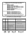
THE INSTALLATION AND OPERATING INSTRUCTIONS IN THIS
MANUAL APPLY TO THE FOLLOWING WOODFIRES:Free standing models:-
MASPORT TALISMAN
MASPORT HORIZON
MASPORT LE 2000, 2000/S, 2000/W
MASPORT LE 3000, 3000/S, 3000/W (Series 2 models)
MASPORT LE 5000, 5000/S, 5000/W (Series 2 models)
MASPORT LE 7000, 7000/S, 7000/W (Series 2 models)
MASPORT LE 7000
MASPORT COLORADO (Series 2)
MASPORT PANORAMA (Series 2) and (Series 3)
MASPORT GRANDVIEW
MASPORT TORONTO
In-built models:-
MASPORT LE 3000 PROVINCIAL (Series 2)
MASPORT LE 3000/S PROVINCIAL (Series 2)
MASPORT LE 3000/W PROVINCIAL (Series 2)
MASPORT LE 3000 PROVINCIAL (Clean Air Zone)
MASPORT LE 7000 PROVINCIAL (Australia)
Note: Models /S have been emission tested for N.Z. without water boosters.
Models /W have been emission tested for N.Z. with water boosters.
CONTENTS OF LOOSE PARTS BAG
(Note: You may not need all these parts for your installation)
Part No.
501682
Quantity
Description
10
M6 Hexagon Nut
501703
501815
501959
4
4
6
M6 Flat Washer
M6 x 35mm Hex. Set Screw
M6 x 12mm Hex. Set Screw
503005
4
503259
4
503388
503459
2
2
593076
1
Self Threading Screw —
12mm long, zinc plated finish
Self Threading Screw —
12mm long, black finish
‘C’ Nut (Spire # SNU 0537)
Self Threading Screw —
25mm long
Installing & Operating Manual
986413
2
‘L’ Bracket
6mm
12mm
Where Used
4 — Pedestal front to pedestal sides
4 — Firebox to pedestal
2 — ‘L’ Brackets to pedestal
4 — Firebox to pedestal
4 — Firebox to pedestal
4 — Pedestal front to pedestal sides
2 — ‘L’ Brackets to pedestal
4 — Heat shield to top of pedestal
4 — Pedestal rear panel to pedestal
2 — Seismic restraint bar to pedestal
2 — Seismic restraint bar to pedestal
2 — Sides or rear of pedestal
25mm
35mm
CONTENTS
INTRODUCTION............................................................................2
FREE-STANDING MODELS — INSTALLATION
UNPACKING ..................................................................................3
ASSEMBLY ....................................................................................3
POSITIONING ............................................................................4, 5
HEARTH (FLOOR PROTECTOR) REQUIREMENTS...................6
CORNER HEARTHS (FLOOR PROTECTORS).............................7
HEARTH (FLOOR PROTECTOR) CONSTRUCTION...................8
INSTALLING THE FLUE...............................................................8
FIXING IN POSITION....................................................................8
FINAL ASSEMBLY ........................................................................9
INSTALLING A WATER HEATING BOOSTER .........................10
IN-BUILT MODELS — INSTALLATION
UNPACKING ................................................................................11
INSTALLATION REQUIREMENTS ............................................11
FIREPLACE ..................................................................................11
MANTEL-SHELF..........................................................................11
HEARTH (FLOOR PROTECTOR)............................................... 12
INSTALLING THE FIREBOX AND FLUE ..................................12
FITTING INTERNAL PARTS.......................................................12
FASCIA .........................................................................................12
INSTALLING A WATER HEATING BOOSTER .........................13
OPERATING INSTRUCTIONS — ALL MODELS
BASIC INFORMATION................................................................14
LIGHTING UP ........................................................................14, 15
OPERATING HINTS ....................................................................15
SAFETY ........................................................................................16
MAINTENANCE...........................................................................17
BEFORE EACH HEATING SEASON...........................................18
THIS BOOK CONTAINS IMPORTANT INFORMATION.
PLEASE KEEP IT IN A SAFE PLACE FOR FUTURE REFERENCE.
1
INTRODUCTION
In the interests of your safety, most building regulatory Authorities in Australia and New
Zealand require any woodfire installation to comply with the relevant National Standard.
They may also have local requirements in addition to those in the Standard so you should
approach your local Building Authority before commencing installation to establish
whether you will require a Permit and whether you will need to meet extra requirements.
All MASPORT Woodfires have been tested to ensure that they will meet the appropriate
safety Standard requirements if the instructions in this book are followed.
Woodfire models covered by this manual have been tested to demonstrate compliance with
current emission Standards in Australia and New Zealand.
WE RECOMMEND THAT THE INSTALLATION OF YOUR MASPORT
WOODFIRE BE CARRIED OUT BY A QUALIFIED SPECIALIST INSTALLER.
IF ANY ELECTRICAL WORK IS REQUIRED, IT MUST BE CARRIED OUT BY
A LICENSED ELECTRICIAN
PLEASE ENSURE THAT ONLY COMPONENTS APPROVED BY MASPORT ARE
USED FOR THE INSTALLATION, as substitutes may adversely affect performance and
might nullify compliance with the requirements of your Standard.
WARNING: THE APPLIANCE AND FLUE MUST BE INSTALLED IN ACCORDANCE WITH
CURRENT INSTALLATION STANDARDS AND THE APPROPRIATE REQUIREMENTS OF
THE RELEVANT BUILDING CODE OR CODES.
CAUTION: MIXING OF APPLIANCE OR FLUE SYSTEM COMPONENTS FROM DIFFERENT
SOURCES OR MODIFYING THE DIMENSIONAL SPECIFICATION OF COMPONENTS MAY
RESULT IN HAZARDOUS CONDITIONS. WHERE SUCH ACTION IS CONSIDERED, THE
MANUFACTURER SHOULD BE CONSULTED IN THE FIRST INSTANCE.
CAUTION: CRACKED AND BROKEN COMPONENTS, e.g. GLASS PANELS OR CERAMIC TILES,
MAY RENDER THE INSTALLATION UNSAFE.
Additionally, for woodfires using water heating devices:WARNING: DO NOT CONNECT TO AN UNVENTED HOT WATER SYSTEM. INSTALL IN
ACCORDANCE WITH AS 3500.4 OR NZS 4603 AND THE APPROPRIATE REQUIREMENTS
OF THE RELEVANT BUILDING CODE OR CODES.
Some areas in New Zealand and Australia have special emission regulations and
MASPORT woodfires are approved for use in those areas. Approval has been given
provided that no modifications are made to the appliance.
In New Zealand areas covered by emission regulations:(I)
Any water heating device must be factory fitted or be a Masport
accessory retro-fitted strictly in accordance with the instructions
on page 10.
(II)
Coal must not be used as a fuel.
(III)
Wood fuel must have a moisture content of less than 25%
2
FREE-STANDING MODELS (See page 11 for in-built models)
UNPACKING
After removal of the shipping carton, open the door and take out all loose parts except the
polystyrene packers above the top baffle. Do NOT discard the top baffle. You may find it more
convenient to lift the door from its hinges at this stage.
Remove and discard the four bolts holding the woodfire to the shipping pallet.
Remove the woodfire from the pallet, lifting only from the lower edge of each side.
DO NOT LIFT BY THE LOWER FRONT PANEL OR THE REAR PANEL.
ASSEMBLY OF FREE-STANDING MODELS
The table inside the front cover will help you identify the various fastenings.
First assemble the pedestal. Secure the two pedestal sides to the front, using four M6x12 set
screws and taking care that the bottom flanges of the side panels align with the bottom flange of
the front panel. The top flange of the front panel will be above the top flanges of the sides. Fit
the slotted pedestal rear panel using the four black 12mm long self threading screws (sharp
points). If your woodfire will have a fan, this will be fitted LATER in place of the pedestal rear
panel. Using the four zinc plated 12mm long self threading screws (blunt points), screw the
bottom heat shield to the top of the pedestal assembly with the turned up ends of the heat shield
facing away from the pedestal. Check that the pedestal surround (foot) and trim (if any) will fit
snugly around the assembled pedestal before tightening all assembly screws fully.
Roll the woodfire carefully onto its back, using the flattened carton to protect the floor.
Taking care that the slotted pedestal rear panel will be at the rear, attach the pedestal to the
firebox using the four M6x 35 set screws, four M6 flat washers and four M6 Hexagon nuts.
Place the washers on the set screws and pass the screws from inside the firebox through the
holes in the pedestal. The nuts will be inside the pedestal. Check the alignment of the pedestal
before tightening the nuts firmly.
Roll your woodfire carefully back into the upright position.
If you are installing a fan, this can now be fitted at the rear of the pedestal in place of the
pedestal rear panel.
3
POSITIONING YOUR FREE-STANDING WOODFIRE
Free-standing woodfires must not be installed in a fireplace or alcove, or under a ceiling of less
than normal height. No wall or other immovable object may be closer to the front of the
woodfire than one metre.
If a water heating accessory is to be fitted, a further positioning restraint is the need to be close
to your hot water storage cylinder (See page 10).
Finalise the installation position for your woodfire only after considering the necessary stove to
heat sensitive wall distances (See Tables below) and checking the practicability of installing the
flue system through the ceiling and roof. Heat resistant walls covered with heat sensitive surface
treatments (e.g. wallpaper or heat sensitive paints) should be regarded as heat sensitive walls.
The flue shielding and the 25mm clearance gap around it above the ceiling will occupy a
diameter of 300mm (Grandview, Colorado and Toronto 325mm), and this must be available
without the removal of structural beams. Flue installations other than strictly vertical ones are
possible. See current Australian and New Zealand Standards for information on flues passing
through walls and eaves.
Detailed dimensional requirements for the flue installation are included with every MASPORT
approved flue system.
NEW ZEALAND — MINIMUM DISTANCES TO HEAT SENSITIVE WALLS (mm)
g
Model
Flue Heat Deflector
A
B
C
D
E
F
R§
Talisman, Horizon
LE 2000
LE 3000
Series 2
LE 5000
Series 2
LE 7000
Series 2
Colorado ¶
Series 2
Toronto
YES - 1200 mm*
NO
YES - 1200 mm*
NO
YES - 1200 mm*
NO
YES - 1200 mm*
NO
YES - 900 mm*
NO
YES - 900mm*
NO
YES - 1200 mm*
NO
YES - 900 mm*
NO
50
300
50
300
50
300
100
505
125
475
125
475
50
300
200
450
300
300
245
270
245
270
325
420
400
400
400
400
345
345
350
350
220
470
275
525
275
525
295
700
320
670
320
670
275
525
395
645
578
578
575
600
575
600
655
750
730
730
730
730
675
675
730
730
50
150
25
225
25
225
50
325
50
300
50
300
50
250
50
250
355
455
380
580
380
580
425
700
425
675
425
675
380
580
458
658
500
645
540
820
540
820
600
990
600
955
600
955
540
820
650
930
Panorama
Series 2 & 3
Grandview
* All Flue Heat Deflectors Polished Stainless Steel with top Heat Dispersal Cap.
¶ Measurements to cabinet, not top panel.
§ Valid only when the room walls are accurately at 90° to each other.
4
g Note: Clearances are for fire hazard only. For durability of finishes or surfaces you
should contact the relevant manufacturer for their specification. MASPORT accepts
no responsibility for the deterioration of surfaces or finishes.
AUSTRALIA
MINIMUM DISTANCES TO HEAT SENSITIVE WALLS (mm) g
WITH THE APPROPRIATE FLUE HEAT SHIELD
Model
A
B
C
D
E
F
R§
Talisman
Horizon
LE 2000
LE 3000 Series 2
LE 5000 Series 2
LE 7000
Colorado Series 2 ¶
Toronto
Panorama Series 2 & 3
Grandview
150*
150*
125
150†
150†
125
125
125
150†
150
350
350
325
325
325
300
350
350
350
350
320*
320*
295
375†
375†
320
320
320
375†
345
628
628
603
655
655
630
680
680
680
730
100
100
100
125
125
100
100
100
125
100
405
405
405
480
480
475
475
475
455
508
575
575
575
680
680
675
675
675
645
720
* May be reduced by 25mm when using the Acorn flue shielding option.
† May be reduced by 25mm when using Acorn or Woodland flue shielding options.
¶ Measurements to cabinet, not top panel.
§ Valid only when the room walls are accurately at 90° to each other.
RECOMMENDED 150mm FLUE OPTIONS:- (All except Colorado, Toronto and Grandview)
Acorn Metal - Special Insulated Flue Kit with 900mm 120˚ polished reflector.
Benja Pty Ltd - Benja Mk II with 900mm decorative heat shield with 120˚ solid back.
Floate Metal - Flomet Super Single with full length decorative heat shield with 120˚ solid
back.
Shamic Sheetmetal - Model 1A with full length decorative heat shield with 180˚ solid back.
(Not tested on Panorama)
Statewide Heating - Model M1 with 900mm enamelled flue shield.
Woodland Fireplaces - Woodland Double Flue System with flat ceiling plate and 900mm
180˚ stainless steel heat shield. For LE3000 Series 2, LE 5000 Series 2
and Panorama Series 2 only.
RECOMMENDED 178mm (7”) FLUE OPTIONS:- (Colorado and Toronto only)
Acorn Metal - Special Insulated Flue Kit with 900mm long half round enamelled mild steel
(or polished stainless steel) flue shield.
Floate Metal - Flomet 7” Super Single Flue System with full length perforated decorative heat
shield with 120˚ solid back. The ceiling plate has a 200mm diameter solid
metal collar extending down 150mm surrounding the decorative shield.
RECOMMENDED 178mm (7”) FLUE OPTIONS:- (Grandview only)
Acorn Metal - Special Insulated Flue Kit with 900mm long half-round polished stainless
steel flue shield.
Floate Metal - Flomet Super Single flue system with full length perforated decorative heat
shield with 120˚ solid back. The ceiling plate has a 200mm diameter
collar extending down 100mm surrounding the decorative shield.
Statewide Heating - Standard 7” Flue Kit with 900mm long half round polished stainless
steel flue shield.
5
HEARTH (Floor Protector) REQUIREMENTS — FREE-STANDING MODELS
Unless your woodfire will be standing on an un-covered fireproof floor which extends at
least as far as the minimum hearth areas shown below, it will be necessary to provide a
hearth for floor protection. See page 8 for construction details.
Where the minimum requirements bring the edge of the hearth nearly to a wall, it is
better to extend the hearth to meet the wall.
AUSTRALIA
W
B
C
D
G
H
J
K
S#
Talisman, Horizon, LE 2000
875
735
300
160
170
435
555
0
885
LE 3000 & LE5000 Series 2
935
840
350
138
225
490
660
0
990
Ditto with Acorn/Woodland Flue Shield
935
840
350
138
225
490
660
0
965
LE 7000
875
840
300
108
195
540
660
0
965
Colorado Series 2 & Toronto
965
940
300
153
195
540
660¶
100
965
Panorama Series 2 & 3
940
915
350
140
225
565
660
0
1065
Ditto with Acorn/Woodland Flue Shield
940
915
350
140
225
565
660
0
1040
Grandview & Series 2
965
1010
300
103
195
610
760
100
1060
H
J
K
© Ash
Hearth
©
Insul.
Hearth
Fl. Defl
No Fl Defl
S#
NEW ZEALAND
W
B
C
D
Talis., Horiz., LE 2000
875
635t
200t
160
170 435
555
0
3
3
685t
935t
LE 3000 Series 2
935
910*
420*
138
225 490
660
0
7
3
960*
1210*
LE 5000 Series 2
935
690t
200t
138
225 490
660
0
3
3
740t
990t
G
LE 7000 Series 2
875
740t
200t
108
195 540
660
0
3
3
840t
1245t
Colorado Series 2
965
740t
200t
153
195 540
660¶
0
3
3
865t
1215t
Toronto
965
740t
200t
153
195 540
660
0
3
3
865t
1215t
Panorama Series 2
935
975*
410*
138
225 565
660
0
7
3
1025*
1275*
Grandview
965
1255*
520*
103
195 610
760
125
7
3
1330*
1580*
* Increase by 80 mm if the hearth top is not at least 50 mm above the floor.
© See page 8 for minimum constructional requirements.
t For practical purposes we recommend increasing these sizes by 100mm.
¶ Measured to cabinet, not top panel.
# Valid only when the fire is exactly at its minimum allowable wall clearance.
6
CORNER HEARTHS (Floor Protectors)
While the information in the previous section details the MINIMUM size of hearth necessary
to comply with the Safety Standards, it may often be desirable to use a somewhat larger area
of hearth for æsthetic reasons. A particular example is when the woodfire is installed
diagonally in a corner. A neater appearance will result if the hearth is carried right into the
corner and is shaped as shown below. The chart facilitates calculation of the MINIMUM
dimensions required for hearths of this shape. Minimum allowable values for dimension ‘E’
are given in the tables on pages 4 and 5.
AUSTRALIA
MINIMUM DIMENSIONS — mm
See pages 6, 8 for construction.
Talisman, Horizon
LE 2000
NEW
ZEALAND
X
Y
X
Y
With Shelf
—
—
880
425t
Without Shelf
880
560
—
—
980
605
1035
650*
LE 3000 Series 2
LE 5000
Series 2
With Shelf
980
605
950
430t
Without Shelf
980
605
—
—
LE 7000 Series 2
With Shelf
—
—
1000
520t
LE 7000
Without Shelf
1000
660
—
—
Colorado Series 2
1025
625
1015
500t
Toronto
1025
625
1015
500t
Panorama Series 2 & 3
980
655
1050
675*
Grandview
1100
725
1250
890*
Your measurement ‘E’ must be added ‘X’ and ‘Y’ to find the appropriate minimum
overall hearth dimensions. See page 4 or 5 for minimum values of ‘E’.
t Increase ‘Y’ by 140mm for our recommended hearth extension.
* Increase ‘Y’ by 120mm if the hearth top is not at least 50mm above the floor.
7
HEARTH (Floor Protector) CONSTRUCTION
In Australia the minimum hearth construction requirement is a sheet of 6mm fibre cement
board. It is usually fastened directly to the floor.
In New Zealand, only the LE 3000 Series 2, the Panorama and the Grandview models require
an insulating hearth. All other current models may be installed on an ash hearth. Naturally, all
models may be installed on insulating hearths if desired. The necessary minimum construction
details for ash and insulating hearths are shown below, and such constructions are suitable for
solid timber or particle board floors. Constructions not suitable as insulating hearths are
bricks or concrete in contact with the flooring material. If, however, the floor is concrete and
no timber is in contact with its lower surface in the area where the hearth would normally be,
a hearth is not required. If tiles or pieces of slate etc. are required for decorative purposes,
they may be glued directly to the concrete floor.
In all cases, in both countries, the hearth must extend right under the woodfire and a durable
top surface will be needed to resist damage from heat or dropped embers. Obvious surface
materials are slate, bricks and ceramic tiles. Gaps in the top surfacing material must be
grouted to prevent the penetration of embers. A trim moulding will provide a neat edge
finish.
INSTALLING THE FLUE
You MUST use a flue system which complies with the current Australian or New Zealand
Standard as appropriate.
In Australia, only flue systems tested with your particular model are approved for use. The
flues and flue heat shields tested in Australia at the time of printing are detailed under the
table on page 4. Flue heat shielding must be fitted unless all heat sensitive material is at least
600mm away from the flue surface.
In New Zealand we recommend the use of genuine Masport flue kits. The flue MUST be
installed in accordance with the detailed instructions accompanying it. Grandview, Toronto
and Colorado ceiling plates should be 450mm square. A flue heat deflector, as detailed on
page 4, may be fitted at the back of the flue (directly above the stove) to achieve the reduced
wall clearances shown in the table. The Masport flue heat deflector (Part No 551481) is
recommended for 150mm flues.
FIXING THE WOODFIRE IN POSITION
Once the flue shielding system has been installed through the ceiling and roof, the woodfire
can be placed in its approximate position on the hearth, and the flue pipes installed. Finally
adjust the stove position making sure the flue is vertical and that the necessary minimum
woodfire-to-wall distances are being achieved. New Zealand Standards require that the
woodfire and hearth be secured to prevent shifting in the event of an earthquake. This is best
done by fastening the woodfire right through the hearth to the floor, using two screws not
less than 12 gauge, or the equivalent size of coach bolts or toggle fasteners. Anchor the
appliance through the holes in the seismic restraint bracket or in the two angle brackets
supplied. The angle brackets attach at each side of the pedestal (except for the LE 2000,
where they attach at the rear). The pedestal can be fastened to the seismic restraint bracket
either before or after fitting the anchor screws. The small centreline hole in the bracket will
help in pre-positioning it.
8
FINAL ASSEMBLY
Before using the woodfire, the internal firebox components must be placed in their correct
positions. No force should be required to fit them, and they can be removed, if desired, for
flue cleaning. However, they MUST be in place, and in good condition, before lighting the
fire.
All Masport models are supplied with either fire-bricks or insulating board to line the firebox.
The LE 2000 has insulating board already fixed in position at the factory. In the other models,
two bricks or boards are to be fitted across the back of the firebox wall, and the others will fit
against the end walls. Each brick or board is fitted in the same way. Angle it into position
with its top corner behind the upper retaining lug, then swing it until it is parallel to the wall
with its bottom corner behind the lower retaining lug. Lower the brick or board into position.
In some models there are two or boards at each end. Fit the metal retaining channel over the
top edges of these bricks to hold them in line. The wider leg of the channel goes next to the
firebox wall.
Carefully remove the polystyrene packing above the firebox top baffle, remembering that the
baffle can be broken by rough handling. Make sure that the baffle is correctly placed on top of
the supporting shelves at each side of the firebox, and that it is back far enough for the two
front corners to drop behind the retaining ribs on top of the shelves. On some models, a metal
reinforcing channel is provided for the baffle. Fit this along the edge of the baffle nearest the
door.
In cases where a pedestal foot is to be fitted, simply fit the trim into the foot and slide the
assembly onto the pedestal, keeping the foot in contact with the hearth all the time to avoid
marking the finish on the sides of the pedestal.
Finally, refit the door, if necessary, and spread the sand provided evenly over the bottom of
the firebox before lighting the first fire.
9
INSTALLING A WATER HEATING BOOSTER
Water heating booster tubes can be fitted to woodfires sold in New Zealand. Fitting a water
booster tube converts an /S model into a /W type. If a tube is retro-fitted, in some cases the
air metering plate must be changed to ensure that emission requirements are still met. In
addition, the LE 3000 and LE 5000 in the ‘Christchurch’ clean air zone will require a special
secondary air tube (see table below). The air metering plate is fitted directly behind the sliding
plate that controls the stove heat output, and it can be reached by removing the air control
knob (remove the screw underneath), and lifting off the air grille.
Water booster tube holes are provided and plugged in the back wall of the free-standing
firebox and the side walls of the in-built model. All plumbing work must meet the
requirements of NZS 4603 unless local building regulations dictate otherwise. Pipe
connections are 1” BSP and the pipe positions are illustrated below. Special piping methods
must be followed to ensure effective circulation, and the hot water cylinder will need to have
an internal riser pipe to two thirds of the cylinder height to discourage unwanted water
circulation when the woodfire is not burning. This internal riser pipe must be connected to
the return pipe from the woodfire.
For effective circulation, the pipes from the woodfire should rise at the rate of one in five
toward the storage cylinder, and ideally the cylinder should be within three metres of the
woodfire. Detailed piping instructions are included in the kit, but two safety requirements
deserve special mention.
THERE MUST BE NO NON-RETURN OR SHUT-OFF VALVES IN THE PIPES
BETWEEN THE WOODFIRE AND THE STORAGE CYLINDER.
A WOODFIRE FITTED WITH A WATER HEATING BOOSTER MUST NOT BE FIRED
UNLESS IT IS CONNECTED TO A VENTED STORAGE CYLINDER FILLED WITH
WATER FREE TO CIRCULATE.
PART NUMBERS OF COMPONENTS REQUIRED FOR WATER BOOSTER
CONVERSIONS IN CHRISTCHURCH AND CANTERBURY CLEAN AIR ZONES
MODEL
CONVERSION
KIT No.
WATER
TUBE No.
METERING
PLATE No.
SECONDARY AIR
TUBE No.
LE 3000 / 5000 Series 2
994019
586044
986178
994010
LE 3000 PROVINCIAL Series 2
995095
586593
995024
No Change
Panorama Series 2
994020
586044
No Change
No Change
Water Pipe Connection Positions
10
IN-BUILT MODELS
(See page 3 for free-standing models)
All current LE Provincial models (Australian and New Zealand), can be fitted with threespeed air circulating fans. (Fans are not permitted in Provincial fires installed in the Clean Air
Zones of Christchurch and Canterbury). These are mounted inside the ash shelf which
protrudes below the firebox door.
Fascia extending kits are available for the LE 3000 Provincial models to extend the fascia size
from 650 high by 810 wide to 700 high by 900 wide to suit larger than normal fireplace
openings. [Part No 986580 (black), 986585 (coffee)].
An optional mantel-shelf with a 38mm higher rear up-stand is available for the LE 7000
Provincial.[Part No 986765 (black)].
UNPACKING
After removal of the shipping carton from the firebox, take out all loose parts. Note that the
firebox door is shipped with the fascia. In the case of the LE 7000 Provincial, the ash shelf
and fan are also shipped with the fascia.
Keeping the fire upright, release it from the shipping pallet by unscrewing the shipping bolts.
INSTALLATION REQUIREMENTS
Please read the INTRODUCTION on page 2, as this applies also to in-built models.
FIREPLACE
For a safe installation the following matters must be attended to.
• The fireplace and chimney must be thoroughly cleaned and checked for soundness.
• The chimney must not connect to a second fireplace.
• The joint between the chimney face and the fireplace surround must be checked and sealed
to prevent leakage if necessary.
• The fireplace recess must have a non-metallic heat resistant surround extending at least
455mm (N.Z.), 480mm (Aust.), or 540mm (for the LE 7000) each side of the recess
centreline and up to at least 810mm above the base of the fireplace recess.
• In New Zealand, the fireplace and chimney must comply with all the relevant Building
Codes, except that the specified separation between the outside of the chimney and timber
construction need not be provided. Timber may touch the outside of any part of the chimney.
• A flue pipe must be fitted right up the chimney, and the space between the flue pipe and
chimney must be ventilated at the top. In Australia the area of this vent must be not less than
10,000mm2, while in New Zealand it must be not less than 13,000mm2. The vent must be
fitted with means to prevent significant ingress of water and debris. The flue must be free to
move up and down at the top as it expands and contracts with temperature changes. This
movement can be about 25mm.
MANTEL-SHELF SHIELDING
The need to shield a heat sensitive mantel-shelf depends on its distance above the woodfire,
and how far it projects forward from the face of the masonry fireplace surround. Heights
shown below are measured from the undersurface of the shelf to the bottom of the fireplace
recess.
In Australia, all shelves less than 1075mm high require shielding.
In New Zealand, all shelves less than 1075mm high require shielding unless they project less
than 75mm and are at least 955mm high.
Where shielding is needed we recommend a sheet metal shield fixed 20mm below the
undersurface of the shelf. It must shield the entire depth of the under-surface of the shelf, and
the 20mm space must be open at the ends and front to allow air to circulate freely.
11
HEARTH (FLOOR PROTECTOR)
LE 3000 Provincial hearths should be at least 900mm wide, and LE 7000 Provincial hearths
must be at least 1080 wide.
MINIMUM HEARTH EXTENSIONS, measured from the face of the masonry
surround:AUSTRALIA — 375mm for the LE 3000 Provincial, and 430mm for the LE 7000
Provincial. ( Both regardless of hearth height).
NEW ZEALAND — For LE 3000/S and /W Provincials:Hearth Elevation
60 or more
50 mm
25 mm
Zero
Min. Hearth extension
300 mm
325 mm
400 mm
450 mm
INSTALLING THE FIREBOX AND FLUE
The flue recommended for use in Australia is a stainless steel chimney kit such as the Shamic
#4. In New Zealand, we recommend the use of the Masport Provincial flue kit.
Measure the fireplace recess and remove bricks as necessary to accept the firebox outer case
which is 560mm high, 590mm wide and 460mm deep for the LE 3000 models. The LE 7000
case is 603mm high, 630mm wide and 485 deep. Clear away any rubble and inspect and seal
the chimney and fireplace as detailed under INSTALLATION REQUIREMENTS.
Check the distance back from the face of the surround to the clear space in the centre of
chimney where the flue will run to determine whether the flue will mate with the flue socket
in the stove without requiring an offset. If an offset is needed, fix it to the lower end of the
assembled flue sections in the chimney and lift the flue assembly up while the firebox case is
pushed back into the recess. Adjust the case position so that it is level and its flange is in line
with the face of the surround. (If a fascia extending kit is being used, the flange should be
10mm forward from the surround face). Where seismic restraint is necessary, screw the case
to the base of the fireplace recess with at least two 12 gauge screws through the holes in the
bottom panel. If space above the case for positioning and fixing the flue is limited, access can
be provided by sliding out the top front section of the case (LE 3000 models only). For the
LE 7000 model, it will be found easier to fit the flue to the firebox spigot if the top baffle
inside the firebox is removed. Removal is described in the MAINTENANCE section under
FIREBOX TOP BAFFLE. Remove the polystyrene packing from above the baffle before
attempting to remove the baffle. The flue can then be lowered into position. Re-fit the sliding
panel with the insulating blanket on top in New Zealand. Do not forget to replace the baffle
and secondary air tube if they have been removed. Instructions for fixing and weatherproofing the top end of the flue are supplied with the flue kit.
FITTING INTERNAL PARTS
The internal components are identical to the free-standing models. See page 10 for FINAL
ASSEMBLY.
FASCIA
All fascias except the LE 7000 are delivered fully assembled and can be simply screwed to
the flange of the firebox case.
To assemble the LE 7000 fascia:Lay the fascia components face down on the floor and use the wafer-head screws to assemble
the two side panels, the mantel-shelf and the bottom brace. (See illustration on page 13). The
wafer-head screws go through the back flanges of the side panels into the flanges of the
mantel-shelf and bottom brace. (See illustration). Make sure the assembly is square.
Once this is complete, carefully turn the fascia over and confirm that the spacing between the
side panels is correct by offering the ash shelf up to the fascia. The ash shelf hangs on two
posts at the lower ends of the side panels. (Feed the mains flex for the fan through the side
panel while placing the shelf in position). First engage the right end of the shelf and then the
left. If the side panel spacing does not permit easy assembly, slacken the wafer-head assembly
screws and adjust as necessary.
12
With the ash shelf removed, fit the fascia to the firebox case, keeping a gap of about 2mm
between the hearth and the lower edge of the fascia. (See illustration)
DOOR
Hook the bottom pivot over the lower end of the hinge pin and lift the door up until the top
pivot drops over the top end of the hinge pin.
ASH SHELF
Hang this on the posts at the bottom of the fascia, taking care to feed the mains flex for the
fan through the fascia side panel as the shelf is lowered into position. Hook the right side on
first, then swing the left side into position.
LOUVRE ASSEMBLY
The primary air control knob must be removed before the louvre assembly can be fitted or
removed. It is retained by a Phillips-head screw from underneath. To avoid damaging the
knob, check that the screw hole and the hole in the plate are in line before replacing the
screw.
INSTALLING A WATER HEATING BOOSTER (New Zealand only)
The necessary piping arrangements must be made for this before the case is fitted into the
recess. The tube may be fitted on either side of the firebox, and the plumbing requirements are
the same as those for the free-standing models. See page 10 for details.
13
OPERATING INSTRUCTIONS — ALL MODELS
BASIC INFORMATION
DOOR HANDLE
Front mounted handles. Swing the door open and shut with the handle in the 12 o’clock
position. Latch the door shut by pushing in on the handle and turning it to the 3 o’clock
position.
Side mounted handles. The door is opened by pulling forward on the lower part of the
handle. Hold the handle in this forward position when shutting the door, finally pushing it
back to vertical to lock the door.
HEAT OUTPUT CONTROL
This control has a sliding action. It is clearly marked with a wedge shaped symbol. Slide the
control toward the wide end of the wedge to increase the heat output and toward the narrow
end to decrease it. A high fire can be shut down rapidly only by starving it of air, and this will
result in undesirable emissions. For this reason, Masport woodfires are designed to settle
down to lower heat outputs comparatively slowly.
OVERNIGHT BURNING
Old fashioned stove designs attempted to achieve long burn times by starving the fuel of air,
thus creating over-rich fuel/air mixtures and emitting pollutants. Modern designs avoid
pollution by eliminating air starvation. This might seem to rule out overnight burning, but this
is not so provided that a suitable fuel is used. Hardwood fuels give longer low-burn times
than softwoods, while thicker pieces of fuel burn longer than thin ones.
FAN OPERATION
The LE 7000 Provincial should not be operated on maximum heat with very dry softwood
unless the fan is operating. Using the fan, except when the fire is set on LOW, will improve
the heating efficiency and distribution of warm air in the room. Usually a medium fan speed
setting will be adequate.
ESSENTIAL ADVICE
• Correct installation, the use of only DRY wood and adherence to the following instructions
will ensure satisfactory performance.
• MAKE SURE THE MINIMUM WOODFIRE-TO-WALL DISTANCES SHOWN ON
PAGES 5 AND 6 ARE ALWAYS MAINTAINED BETWEEN THE WOODFIRE AND
ANY HEAT SENSITIVE MATERIAL SUCH AS FURNITURE, WINDOW DRAPES,
FIREWOOD ETC.
• DO NOT ATTEMPT TO BURN LIQUID FUELS OF ANY KIND.
• WOODFIRES FITTED WITH WATER HEATING BOOSTERS MUST NOT BE LIT
UNLESS THE BOOSTER IS CONNECTED TO A VENTED STORAGE CYLINDER
FILLED WITH WATER FREE TO CIRCULATE. THERE MUST BE NO SHUT-OFF OR
NON-RETURN VALVES IN THE PIPING SYSTEM.
LIGHTING UP
Before lighting the first fire, spread the sand provided evenly over the floor of the firebox.
Subsequently, always leave sand or ash to the level of the tops of the floor ribs.
Slide the heat output control fully to the hot position.
Crumple up several double sheets of newspaper and place them in the centre of the firebox.
Build a pyramid of thin, dry kindling wood on the paper with some heavier pieces on top.
Light the paper at the bottom and leave the door slightly ajar until the kindling has ‘caught’,
then latch the door shut firmly.
WARNING: DO NOT USE ANY FLAMMABLE LIQUID SUCH AS PETROL,
KEROSINE, OIL ETC. TO START OR REKINDLE THE FIRE.
14
LIGHTING UP (Continued)
When the kindling is well alight, open the door slowly and add some larger pieces of wood.
Do not throw fuel pieces into the firebox as this could damage the top
baffle and the insulating boards or firebricks.
Close and latch the door firmly.
Move the heat output control away from the maximum position only after the fire is well
established. We recommend running at full heat for up to one hour after lighting as this will
minimise creosote build-up in the flue. The control can then be set wherever desired. A new
woodfire should not be run at higher than half setting after the first 30 minutes until it has
been used for a total of 8 hours.
The special high temperature paint on the firebox will emit some smoke as it cures during the
first few minutes of running. This is quite normal.
OPERATING HINTS FOR CLEAN BURNING AND BEST EFFICIENCY
• Use only wood that has been air dried in a sheltered stack, preferably for at least 12 months.
If moist fuel must be used, add it only to a really hot fire, mixing it with a large proportion of
dry fuel. In Clean Air Zones, only wood must be used as fuel, and it must have a moisture
content not greater than 25% (measured on a wet weight basis).
• Do not burn driftwood or chemically treated wood, as salt will corrode the woodfire and
chemicals can create poisonous gases and leave toxic ash.
• Add fuel reasonably often. A large fuel load placed on a dying fire can drop combustion
temperatures undesirably.
• Avoid large smouldering fires. A small intense fire is more efficient.
• Move the heat control to maximum for a minute or so and turn off the air circulating fan (if
fitted) before opening the door on a low burning fire. This will clear away any fumes in the
firebox.
• Always open the door SLOWLY, and close and latch it shut securely again as soon as
possible after re-loading.
• When loading fuel, place the pieces of wood in a front-to-back direction to ensure good air
access and the cleanest possible burning. To achieve this, wood pieces for the Provincial
Clean Air Zone (Christchurch) model should be generally about 250mm long, and in any case
should not exceed 300mm in length.
• Load fuel carefully to avoid damage to the insulating boards, firebricks or
top baffle.
• If smoke wafts into the room while the door is open, first check that make-up air can flow
freely into the room to replace the air passing up the flue. (See box below). Then check that
the flue is not obstructed in any way, particularly by the rain cap being too close to the end of
the flue. If these checks do not uncover the fault, add an extra length of flue (bracing it, if
necessary) to counteract the down draught effects caused by roof shape, nearby buildings,
hills or trees.
• Switch off the circulating fan (if fitted) when the fire is burning at low heat outputs. Use
only the slow fan speed at medium heat output, moving to the higher speed(s) only when full
heat output has been reached.
• Adjust the door to eliminate any minor leakage. (See MAINTENANCE - page 17). Serious
leakage will require a new door seal.
REMEMBER, FOR THE FIRE TO DRAW PROPERLY, AIR MUST BE ABLE
TO ENTER THE ROOM WHERE YOUR WOODFIRE IS INSTALLED. YOU
MAY HAVE TO LEAVE A DOOR SLIGHTLY OPEN AND PERHAPS A
WINDOW ELSEWHERE IN THE HOUSE IF YOUR HOME IS OF MODERN
AIRTIGHT CONSTRUCTION. LEAVING THE ROOM DOOR OPEN WILL
HELP SPREAD WARMTH THROUGH THE REST OF YOUR HOME.
15
SAFETY
• Always keep children well away from the woodfire when it is alight.
• Do not put furniture, clothing, firewood or other combustibles near the woodfire. The
minimum safe distance is 420mm from the sides and 1 metre from the front.
• Do not leave the fire unattended with the door open.
• Accidental fires can be caused by wrapping seemingly cold ashes in paper. It is much safer
to place ashes outside in a metal container with a close fitting lid.
• If a fire is burning up inside the flue, slide the heat output control to the low heat position
and call the Fire Service. DO NOT OPEN THE WOODFIRE DOOR.
• If you have had a flue fire, inspect your flue for damage before lighting another fire.
• Do not modify your woodfire in any way without obtaining written permission from the
Manufacturers.
• Do not use the woodfire if the glass is broken. Replace it only with the correct ceramic
glass, available from your MASPORT dealer.
16
MAINTENANCE
ASH REMOVAL
This should be necessary only very occasionally. Simply shovel out any excess, always
leaving a bed of sand or ash to the tops of the ribs on the bottom of the firebox.
CLEANING THE GLASS
A good hot fire will burn away any deposits left from a long slow burn. If desired, a NONCAUSTIC oven cleaner can be used.
CLEANING THE CABINET OR FASCIA
A damp rag with a touch of household detergent is sufficient to maintain the finish.
ADJUSTING THE DOOR LATCH
If the handle is front mounted, the latch can be adjusted to overcome settling of the door
gasket by transferring a washer to the outside of the door catch spindle. If the handle is side
mounted, the latch is adjusted by rotating the door catch peg. First undo the lock-nut on the
inside of the peg, then rotate the peg to the position where the cam portion gives the right
locking pressure. Holding the peg in this position, re-tighten the lock nut. The hinge on all
models can also be adjusted inward if necessary. Move it in about a millimetre at top and
bottom to maintain an even gasket pressure.
CLEANING INSIDE
If you wish to clean the flue or clear away creosote debris, the internal components can be
removed easily (See below). We recommend that you check the condition of all internal
components at least once a season to make sure they are still serviceable.
FIREBOX TOP BAFFLE
The special top baffle material operates at very high temperature to ensure clean burning.
Take care not to knock and damage it. For flue cleaning or baffle replacement the secondary
air tube must first be removed by withdrawing the two ‘L’ shaped pins. Before removing the
tube, note the direction of the air outlet holes so that it can be reassembled correctly. Slide
the tube slightly to one side and withdraw it. When replacing the baffle, ensure that it is
sitting on top of the supporting shelf at each end and that it is pushed right to the back until
the front corners drop behind the small retainer ribs on the shelves. Re-fit the secondary air
tube, taking care to replace both retaining pins, and making sure it is correctly oriented.
FIREBOX LINERS
While the insulating boards or firebricks are durable, they will eventually require replacement.
Replace them if they show significant deterioration.
FAN MAINTENANCE
The fan should need little attention other than occasionally removing it to clean dust and lint
from the impeller. First unplug the fan from the power point. Fans on in-built fires can be
accessed by lifting off the ash shelf. Fans on free-standing fires are reached by removing the
rear of the pedestal. On internally switched fans, first gently ease off the speed control knob,
taking care to pull it off squarely. Remove the four screws (two on the Panorama and
Grandview) which hold the fan box in position. If the fan is internally switched, move it
slightly away from the switch end and withdraw it completely. In the case of the Panorama
and Grandview, lift the fan off the two top support pegs and then withdraw it. In all cases, no
wires need to be uncoupled. Clean the impeller blades carefully by blowing or vacuuming,
and reassemble in the reverse order.
CLEANING THE FLUE
This may be needed about once a year or more frequently under adverse conditions. Signs of
creosote and soot build-up are inadequate draught, smoking when the door is opened and a
dull thud when the outside of the flue is tapped. A blocked flue can be cleaned only by
sweeping. DO NOT USE CHEMICAL CHIMNEY CLEANERS.
FLUE INSPECTION
Check regularly that the flue is sound, particularly the metal base of enamelled flues.
17
BEFORE EACH HEATING SEASON.
To ensure continued safety, check the condition of the following items, replacing, if
necessary, with only Masport approved spare parts.
1. The flue system, particularly flue sections nearest the firebox.
2. The firebox top baffle.
3. The firebox liners (bricks and boards).
4. The door gasket.
MASPORT WOODFIRES ARE MANUFACTURED IN NEW ZEALAND BY
MASPORT LTD. 1/37 MT WELLINGTON HIGHWAY.
P.O. BOX 14-349 PANMURE, AUCKLAND NEW ZEALAND.
MASPORT WOODFIRES ARE DISTRIBUTED IN AUSTRALIA BY
MASPORT PTY LTD.
P.O. BOX 533, MORDIALLOC, VICTORIA.
18