1
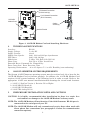
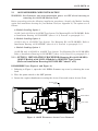
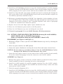
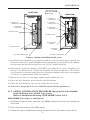
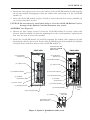
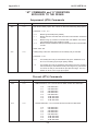
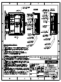
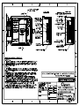
1015N-2MFM-1A
FIELD MANUAL
1015N-2M DIAL-UP MODEM
OPTION CARD
FOR SYSTEM 1010N
FLOWMETERS
FOR TECHNICAL ASSISTANCE
Call: (800) 275-8480
(631) 231-3600
Fax: (631) 231-3334
E-mail: [email protected]
FOR GENERAL INFORMATION
Website: www.controlotron.com
E-mail: [email protected]
Or: [email protected]
Copyright©2006 Siemens Energy & Automation, Inc. All Rights Reserved
Made in the USA
IMPORTANT NOTICE
Controlotron is now part of:
Siemens Energy & Automation, Inc.
Process Instrumentation Business Unit (PI BU)
CoC Ultrasonic Flow
1015N-2M DIAL-UP MODEM
OPTION CARD
FOR SYSTEM 1010N
FLOWMETERS
This equipment contains components that are
susceptible to electrostatic discharge (ESD).
Please observe ESD control measures during
the handling and connection process.
Field Manual 1015N-2MFM-1A
June 2006
For use with Operating System
Software Version 2.00.15 or later
Prepared By
Date
Reviewed By
Date
FOR TECHNICAL ASSISTANCE:
Call: (800) 275-8480
(631) 231-3600
Fax: (631) 231-3334
E-mail: [email protected]
FOR GENERAL INFORMATION:
Website: www.controlotron.com
E-mail: [email protected]
Or: [email protected]
Copyright©2006 Siemens Energy & Automation, Inc. All Rights Reserved
Made in the USA
Printed June 2006
Manual Changes
NOTE: For the latest updates and revisions to this field manual go to
www.controlotron.com/downloads.htm and check the Product Manual
listing.
1015N-2MFM-1A
Table Of Contents
TABLE OF CONTENTS
Page
1.
2.
2.1
2.2
2.3
3.
4.
5.
5.1
5.1.1
5.1.2
5.1.3
5.2
5.3
6.
7.
Introduction ...................................................................................................... 1
1015N-2M Modem Card Setup ...................................................................... 1
Option 1 Mounting Kit 1015N-2M-MK1 ...................................................... 1
Option 2 Mounting Kit 1015N-2M-MK2 ...................................................... 1
Option 3 Mounting Kit 1015N-2M-MK3 ...................................................... 1
Figure 1. 1015N-2M Modem Card and Attaching Hardware ................ 2
Technical Specifications ................................................................................. 2
1010N Flowmeter System Requirements .................................................. 2
Preliminary Installation Notes and Cautions ........................................... 2
1015N-2M Modem Card Installation ........................................................... 2
Module Loading Option 1 .......................................................................... 3
Module Loading Option 2 .......................................................................... 3
Module Loading Option 3 .......................................................................... 3
Option 1 Installation Procedure (Mounting Kit 1015N-2M-MK1) ....... 3
Figure 2. 1010N Flowmeter Access Cover Removal ............................... 3
Figure 3. Option 1 Installation (side view) ............................................. 4
Option 2 Installation Procedure (Mounting Kit 1015N-2M-MK2) ....... 5
Figure 4. Option 2 Installation (side view) ............................................. 6
Option 3 Installation Procedure (Mounting Kit 1015N-2M-MK3) ....... 6
Figure 5. Option 2 Installation (side view) ............................................. 7
Setting 1010N Flowmeter RS-232 Parameters ......................................... 8
Telephone Line Connections ........................................................................ 8
Communications Configuration ................................................................... 9
Windows HyperTerminalTM Setup ............................................................... 9
1015N-2M Reconfiguration Procedure ..................................................... 9
APPENDICES
Appendix A
“AT” Command Set and “S” Registers .............................................. A-1
“AT” Commands .................................................................................. A-2
“S” Registers ........................................................................................ A-4
“AT” Commands and “S” Registers Exclusive to the PE2400 ......... A-5
Dial Modifiers ................................................................................ A-5
Ampersand (AT&) Commands ..................................................... A-6
Percent (AT%) Commands ........................................................... A-6
“S” Registers .................................................................................. A-7
Appendix B
Engineering Drawings .......................................................................... B-1
i
1015N-2MFM-1A
1015N-2MFM-1 MODEM CARD
INSTALLATION INSTRUCTIONS
1.
INTRODUCTION
The 1015N-2M Modem Card is one of three option cards used for remote communications
within the Controlotron 1010N family of flowmeters. External communication is achieved
through an on board dial-up miniature modem with asynchronous line speeds of 2400 bps,
1200 bps, or 300 bps. Implementation of Windows HyperTerminal TM or any other
communication software allows for the direct control of the modem’s Hayes compatible
command set.
2.
1015N-2M MODEM CARD KITS
2.1
OPTION 1 MOUNTING KIT 1015N-2M-MK1
Description
Part Number
Qty
Cover, Communication Module
Screw, Captive 6-32 x 1/2
Label, Controlotron ID
Standoff, Threaded, Cover Mount
Standoff, Threaded, PCB Support
Cover, Analog Input Module
Installation Drawing
Installation, Wiring Drawing
Insulator, Syscom shield, 1010N
1010-436-1
4006M07F09
1010-257
1010-433-1
1010-434-1
1010-379
1015N-2M-MK-7
1015N-2M-7
1010-263
1
1
1
1
4
1
1
1
1
2.2
OPTION 2 MOUNTING KIT 1015N-2M-MK2
Description
Part Number
Qty
Cover, I/O Board
Screw, Captive 6-32 x 1/2
Label, Controlotron ID
Standoff, Cover Mount
Standoff, Threaded, PCB Support
Installation Drawing
Installation, Wiring Drawing
1010-446-1
4006M07F09
1010-257
1010-447-1
1010-434-1
1015N-2M-MK-7
1015N-2M-7
1
1
1
1
4
1
1
2.3
OPTION 3 MOUNTING KIT 1015N-2M-MK3
Description
Part Number
Qty
Cover, I/O Board
Screw, Captive 6-32 x 1/2
Label, Controlotron ID
Standoff, Cover Mount
Standoff, Threaded, PCB Support
Installation Drawing
Installation Drawing
Installation, Wiring Drawing
1010-446-2
4006M07F09
1010-257
1010-447-1
1010-434-1
1015N-2M-MK-7
1015N
1015N-2M-7
1
1
1
1
4
1
1
1
1
1015N-2MFM-1A
TB1 Network Connection
(2-Wire Hook Up)
Con 2 Network Connection
(RJ11 Connector)
1015N-2M
Modem Card
Captive
Screws (4)
Module ID Label
Top View
Side View
Figure 1. 1015N-2M Modem Card and Attaching Hardware
3.
TECHNICAL SPECIFICATIONS
Interface:
RS-232
Supply Voltage:
5 volts DC
Supply Current:
48 mA
Modem Line Speeds:
2400, 1200 and 300 bps Asynchronous
DTE Rates:
2400, 1200, 300 bps
Modulation:
V.22bis, V.22, Bell 212A, Bell 103
Phone Line:
Dial Up or 2 Wire Leased Line
Extended Hayes Command Set Compatibility
Error Correction / Error Detection: None
Operating Environment: -40 to 85 degrees C / 0 to 95% Humidity (non-condensing)
4.
1010N FLOWMETER SYSTEM REQUIREMENTS
The System 1010N Flowmeter operating system must be revision level 2.0 or later for the
1015N-2M Modem Card to function properly. In addition, the 1015N-2M Modem Card
requires 1010N system hardware of the following levels in order to work. Refer to the
appropriate 1010N user manual installation/outline drawings for circuit board locations.
a. 1010N-1-5 SysCom Version 3, Revision. D2 or Higher
b. 1010N-2K3 I/O Board A2
c. 1010N-8M-5 I/O Board A3
d. 1010N-7K2 Analog I/O A2
5.
PRELIMINARY INSTALLATION NOTES AND CAUTIONS
CAUTION: It is highly recommended that installation be done in a static free
environment or damage to the 1015N-2M Modem Card may result.
NOTE: The 1015N-2M Modem will not function if the 1010 flowmeter RS-232 port is
connected to the serial port of your PC.
NOTE: The 1015N-2M Modem will only transmit and receive data when used with
direct phone line connections (see paragraph 5.3 below for communication
connection options).
2
1015N-2MFM-1A
5.1
1015N-2M MODEM CARD INSTALLATION
WARNING: Set flowmeter and instrumentation power to OFF when inserting or
removing the 1015N-2M Modem Card.
Before proceeding with the following installation procedures, identify the Module Loading
option and installation drawing for your Modem Card (see Appendix A). The options are as
follows:
a. Module Loading Option 1
1010N-5 with 1010N-2 in 1010N/DN Type System. Use Mounting Kit 1015N-2M-MK1. Refer
to Installation Drawing 1015N-2M-MK-7 (sheet 1 of 3). Proceed to paragraph 5.1.1.
b. Module Loading Option 2
1010N-2 only in 1010N/DN Type System. Use Mounting Kit 1015N-2M-MK2. Refer to
Installation Drawing 1015N-2M-MK-7 (sheet 2 of 3). Proceed to paragraph 5.1.2.
c. Module Loading Option 3
1010N-8M with 1010N-2M in 1010MN Type System. Use Mounting Kit 1015N-2M-MK3.
Refer to Installation Drawing 1015N-2M-MK-7 (sheet 3 of 3). Proceed to paragraph 5.1.3.
5.1.1 OPTION 1 INSTALLATION PROCEDURE (Mounting Kit 1015N-2M-MK1)
1010N-5 Module with 1010N-2 Module in 1010N/DN Type System
(Refer to Installation Drawing 1015N-2M-MK-7 sheet 1 of 3)
DISASSEMBLY (see Figure 2 and Figure 3)
1. Referring to Figure 1, open the 1010 NEMA flowmeter top cover by releasing the cover
latch.
2. Place the power switch to the OFF position.
3. Loosen the captive thumbscrew securing the Access Cover and remove Access Cover.
Access Cover
Screw
1010N
Power Switich
Cover Latch
Figure 2. 1010N Flowmeter Access Cover Removal
3
1015N-2MFM-1A
CAUTION: Do not connect a serial data cable to J1 on the 1015N-2M Modem Card or
damage to the Modem Card and flowmeter may result.
4. Loosen the four captive screws (1) at the corners of the 1010N-2 module (7) and carefully
lift out the module disengaging it from the connector on the 1010N-5 module (2).
5. Lift off the shield (3) covering the 1010N-5 module (2).
6. Leave the 1010N-5 module in place. Check to assure that the four corner standoffs (4) are
securely threaded in place.
ASSEMBLY (see Figure 3)
7. Install shield (5) supplied with the 1015N-2M-MK1 mounting kit and cover the 1010N-5
module. Note: This shield replaces the shield removed in Step 5 above.
8. Remove the four captive screws (1) from the 1010N-2 module loosened in Step 4 above.
Install standoffs (6) from mounting kit in the vacant positions.
9. Install the 1010N-2 module (7) carefully engaging connector P1 to the 1010N-5 module (2).
Secure by threading the four standoffs (6) installed in Step 5 above with their mates on
the 1010N-5 module.
10. Check for properly alignment of P1.
Serial Data Cable - Not
used with 1015N-2M
Modem Card.
START VIEW
(11) 1010N-2 I/O
Module Cover
(9) 1015N-2M
Modem Card
(11) 1010N-2 I/O
Module Cover
(7) 1010N-2
I/O Module
(9) 1010N-2 I/O Module
(12) Captive Screw
(12) Captive Screw
(10) Cover Mount
Standooff
(1) 1010N-2 Captive Screws
(6) Threaded Standoff
(3) 1010N-5 Analog Module Shield
(5) 1010N-5 Analog
Module Shield
(4) Threaded Standoffs
(4) Threaded Standoffs
(2) 1010N-5 Analog Module Assy
(2) 1010N-5 Analog Module Assy
Figure 3. Option 1 Installation (side view)
4
FINISH VIEW
1015N-2MFM-1A
11. Install the 1015N-2M Modem Card (9) on top of the 1010N-2 module (7) carefully engaging
connector P1 on the 1015N-2M with its mate P1 on the 1010N-2 module. Secure the 1015N2M by engaging its four captive screws with the four standoffs on the 1010N-2 module.
12. Install the large threaded cover mount standoff (10) from the mounting kit through the
hole at the center of the 1015N-2M Modem Card (9) and into the threaded receptacle on
the shield (5) previously installed in Step 7.
13. Referring to installation drawing 1015N-2M-7 (see Appendix A), plug telephone jack into
J4 of the Modem Card. Thread the telephone line plug through one of the System 1010
flowmeter access holes and plug it into a standard telephone outlet (refer to paragraph
5.3 below for communication connection options).
14. Replace Access Cover and finger tighten captive thumbscrew (12).
15. Place the 1010 flowmeter power switch to the ON position.
16. Close the 1010 flowmeter top cover by locking the cover latch.
17. Proceed to paragraph 5.2 to set 1010N flowmeter RS-232 parameters.
5.1.2 OPTION 2 INSTALLATION PROCEDURE (Mounting Kit 1015N-2M-MK2)
1010N-2 Module only in 1010N/DN Type System
(Refer to Installation Drawing 1015N-2M-MK-7 sheet 2 of 3)
DISASSEMBLY (see Figure 2 and Figure 4)
1. Referring to Figure 2 above, open the 1010 NEMA flowmeter top cover by releasing the
cover latch.
2. Place the power switch to the OFF position.
3. Loosen the captive thumbscrew securing the Access Cover and remove Access Cover.
CAUTION: Do not connect a serial data cable to J1 on the 1015N-2M Modem Card or
damage to the Modem Card and flowmeter may result.
4. Loosen the four captive screws (1) at the corners of the 1010N-2 module (2) and carefully
lift out the module disengaging it from the connector on the 1010N-1 module.
ASSEMBLY (see Figure 4)
5. Remove four captive screws (1) from the 1010N-2 module (2) loosened in Step 4 above.
Install standoffs (3) from the mounting kit in the vacant positions.
6. Install the 1010N-2 module (2) carefully engaging connector P1 to the 1010N-1 module.
Secure module by threading the four standoffs (3) installed in Step 5 above with their
mates on the 1010N-1 module.
7. Check for properly alignment of P1.
8. Install the 1015N-2M Modem Card (4) on top of the 1010N-2 module (2) carefully engaging
connector P1 on the 1015N-2M with its mate P1 on the 1010N-2 module. Secure the 1015N2M by engaging its four captive screws (1) with the four standoffs (3) on the 1010N-2 module.
5
1015N-2MFM-1A
Serial Data Cable - Not
used with 1015N-2M
Modem Card.
START VIEW
FINISH VIEW
(7) 1010N-2 I/O
Module Cover
(7) 1010N-2 I/O
Module Cover
(4) 1015N-2M
Modem Card
(2) 1010N-2 I/O
Module Assy
(2) 1010N-2 I/O
Module Assy
(8) Captive Screw
(8) Captive Screw
(5) Cover Mount
Standoff
(1) Captive Screws
(3) Threaded
Standoff
(6) 1010N-1 Module Shield
(6) 1010N-1 Module Shield
Figure 4. Option 2 Installation (side view)
9. Install the large threaded cover mount standoff (5) from the mounting kit through the
hole at the center of the 1015N-2M Modem Card, through the spacer on the 1010N-2 module
and then into the threaded receptacle on the 1010N-1 module shield (6).
10. Referring to installation drawing 1015N-2M-7 (see Appendix A), plug a telephone jack
into J4 of the Modem Card. Thread the telephone line plug through one of the System
1010 flowmeter access holes and plug it into a standard telephone outlet (refer to paragraph
5.3 below for communication connection options).
11. Replace Access Cover (7) and finger tighten captive thumbscrew (8).
12. Place the 1010 flowmeter power switch to the ON position.
13. Close the 1010 flowmeter top cover by locking the cover latch.
14. Proceed to paragraph 5.2 to set 1010N flowmeter RS-232 parameters.
5.1.3 OPTION 3 INSTALLATION PROCEDURE (Mounting Kit 1015N-2M-MK3)
1010N-8N Module with 1010MN Type System
(Refer to Installation Drawing 1015N-2M-MK-7 sheet 3 of 3)
DISASSEMBLY (see figure 2 and figure 5)
1. Referring to Figure 2 above, open the 1010 NEMA flowmeter top cover by releasing the
cover latch.
2. Place the power switch to the OFF position.
3. Loosen the captive thumbscrew securing the Access Cover and remove Access Cover.
6
1015N-2MFM-1A
4. Loosen the four captive screws (1) at the corners of the 1010N-8M module (2) and carefully
lift out the module disengaging it from the ribbon cable connecting it to the 1010N-2M
module (3).
5. Leave the 1010N-2M module in place. Check to assure that the four corner standoffs (4)
are securely threaded in place.
CAUTION: Do not connect a serial data cable to J1 on the 1015N-2M Modem Card or
damage to the Modem Card and flowmeter may result.
ASSEMBLY (see Figure 5)
6. Remove the four captive screws (1) from the 1010N-8M module (2) in Step 4 above and
discard. Install standoffs (5) from the mounting kit in the vacant positions, replacing the
four 4-40 hex nuts to secure the standoff.
7. Install the 1010N-8M module (2) carefully engaging the ribbon cable connector (6) and
dressing the cable for the best fit. Secure cable by threading the four standoffs (5) installed
in Step 6 above with their mates on the 1010N-2M module (3).
Serial Data Cable - Not
used with 1015N-2M
Modem Card.
START VIEW
(10) 1010N-8M I/O
Module Cover
FINISH VIEW
(10) 1010N-8M I/O
Module Cover
(7) 1010N-8M I/O Module
(11) Captive Screw
(11) Captive Screw
(8) Cover Mount Standoff
(2) 1010N-8M I/O Module
(2) 1010N-8M I/O Module
(3) 1010N-2M
Analog Module
(3) 1010N-2M
Analog Module
(1) Captive Screws
(5) Threaded Standoffs
(4) Threaded Standoffs
(4) Threaded Standoffs
System Computer Shield
(6) 1010N-8M
(9) 1010N-2M
with Shield
Dress Ribbon Cable
Between Modules
Figure 5. Option 3 Installation (side view)
7
System
Computer
Shield
1015N-2MFM-1A
8. Install the 1015N-2M Modem Card (7) on top of the 1010N-8M module (2) carefully engaging
connector P1 on the 1015N-2M with its mate P2 on the 1010N-8M module. Secure the
1015N-2M by engaging its four captive screws (1) with the four standoffs (4) on the 1010N8M module.
9. Install the large threaded cover mount standoff (8) from the mounting kit through the
hole at the center of the 1015N-2M Modem Card, through the standoff on the 1010N-8M
module and then into the threaded receptacle on the 1010N-2M module shield (9).
10. Referring to installation drawing 1015N-2M-7 (see Appendix A), plug a telephone jack
into J4 of the Modem Card. Thread the telephone line plug through one of the System
1010 flowmeter access holes and plug it into a standard telephone outlet (refer to paragraph
5.3 below for communication connection options).
11. Replace Access Cover (10) and finger tighten captive thumbscrew (11).
12. Place the 1010 flowmeter power switch to the ON position.
13. Close the 1010 flowmeter top cover by locking the cover latch.
14. Proceed to paragraph 5.2 to set 1010N flowmeter RS-232 parameters.
5.2
SETTING 1010N FLOWMETER RS-232 PARAMETERS
Set the RS-232 parameters on the 1010N flowmeter to match the 1015N-2M Modem Card as
follows:
l
l
l
l
5.3
Baud Rate: 2400
Parity: Odd
Data Bits: 7
Line Feed: Yes
TELEPHONE LINE CONNECTIONS
The 1015N-2M Modem Card contains an FCC-approved Data Access Arrangement (DAA) and
may be connected to your conventional subscriber telephone line. It is suggested that you
consult with your phone service provider and/or telecommunications specialist when
connecting the modem to other types of telephone networks.
If the equipment is installed in a location where lightning strikes are possible, reduce this
risk by providing your phone line and AC-power input with surge and lightning protection.
Connection to the telephone line is made in one of the follows ways:
1. Directly plug your telephone line into the modular connector RJ11 on PE2400 of the Modem
Card (refer to Figure 1 and installation drawing 1015N-2M-7), or
2. Connect the two modular connectors together on the Modem Card with the supplied Modem
Cable Assembly (P/N 1015-154) and then plug your telephone line to the 2-wire terminal
block TB1 on the Modem Card (refer to drawing 1015N-2M-7 in Appendix B).
NOTE: When connecting your telephone line observe the following:
Connect the Green wire (Ring Signal) to TB1-1 and the Red wire (TIP) to TB1-2.
Once the telephone line connection is completed, simply turn the 1010N flowmeter power on
and the modem is ready for use. The modem’s communications parameters are re-loaded
every time power is applied.
8
1015N-2MFM-1A
6.
COMMUNICATIONS CONFIGURATION
The 1015N-2M Modem Card has been pre-configured at the factory to allow for proper interface
with Controlotron’s System 1010N flowmeters.
CAUTION: The 1015N-2M Modem Card will not function properly if the preconfigured settings are altered. If the settings are altered, refer to
reconfiguration procedure below.
7.
WINDOWS HyperTerminalTM SETUP
Step 1. Invoke HyperTerminalTM (generally found in the Program Files / Accessories Folder).
Step 2. Give your connection a name in the space provided.
Step 3. Type in your meter’s telephone number.
Step 4. Then click on Modify, then Configure and select 2400 baud as the modem speed.
Step 5. Now click on Advanced Tab and set Data Bits to 7 and Parity to Odd. You may leave
Stop Bits at 1.
Step 6. Then click on Settings, Terminal Setup and pick VT-100 as your preferred terminal
emulation. Then click OK.
Step 7. Now click on Dial and your modem should dial up the flowmeter.
Step 8. Once your modem answers (you should hear the carrier tones while the modems are
negotiating), click on ‘?’ to see the list of available direct execute commands from the
meter.
Step 9. If you wish to use the meter menu, just type: Menu.
Step 10. You can direct HyperTerminalTM to save the contents of your session to a named file
by clicking on Transfer and then Capture Text. You may use the default file name to
capture the flow meter data, which may then be copied to another file using your text
editor.
Step 11. To hang up, simply terminate HyperTerminalTM and the remote modem will hang up
automatically and ready itself for the next call.
1015N-2M Reconfiguration Procedure
To reconfigure the 1015N-2M Modem Card to factory settings (see Appendix A for commands),
proceed as follows:
1.
2.
3.
4.
Set up HyperTerminalTM as in the first six steps of Section 7 above.
Type: AT &F &W0 &W1 and press <ENTER> key. (Modem prints out: OK.)
Type: AT E0 M0 Q1 &C1 S0=1 &W0 &W1 and press <ENTER> key.
Type: AT &V and press <ENTER> key. Verify on the terminal that the following commands are individually stored in:
Active Profile: E0 M0 Q1 &C1 S01=1 &W0 &W1
Stored Profile 0: E0 M0 Q1 &C1 S01=1 &W0 &W1
Stored Profile 1: E0 M0 Q1 &C1 S01=1 &W0 &W1
5. Complete steps 7 through 11 of Section 7 above.
9
1015N-2MFM-1A
Appendix A
APPENDIX A
“AT” COMMAND SET and “S” REGISTERS
The command set for the 1015N-2M modems is fully compatible with the Hayes AT command
set.
The modem is controlled and configured by the AT (attention command). Each command
consists of the following elements (with exception of the A/and the +++ command which
will be discussed later).
1. The two character sequence AT
2. A command
3. A command parameter
4. A carriage return
A command is not entered until a carriage return <ENTER> is entered. Spaces entered
are ignored. For example, to enter the command ‘Answer’, type ATA and <ENTER>.
Some commands do not have parameters. Any missing parameters in a command are
assigned the value zero, which may be a valid parameter for the command. AT <ENTER>
without a command serves as a wake up code and an “OK” appears on the screen.
The modem queues commands in a 40-character command line. The command line begins
with AT and can have several commands. A separator is not required between the
commands.
The command line format is:
AT command (parameter) command (parameter) ... (enter)
When a carriage return is received, (which terminates the command line), the commands
are performed in the order in which they are sent to the modem. If more than 40 characters
are sent to the modem, an error occurs and all commands must be re-entered.
The tables on the following pages provide the AT and S-Register commands for the PE2400.
A single asterisk (*) indicates the command is not supported by the PE2400.
A double asterisk (**) indicates that the command has a different meaning for the PE2400.
A-1
1015N-2MFM-1A
Appendix A
“AT” Commands
Command
Function
Command
Basic AT Commands
AI
A
B0
B1
C1
Dn
E0
E1
F0
F1
F3
F4
F5
H0
H1
10
11
12
13
14
15
16
L0
L1
L2
L3
M0
M1
M2
M3
N0
N1
00
01
P
Q0
Q1
Sn
Sn?
=v
?
T
V0
V1
W0
W1
W2
Function
X0 Report basic call progress result codes, i.e., OK,
CONNECT, RING, NO CARRIER (also, for busy,
if enabled, and dial tone not detected),
NO ANSWER and ERROR.
X1 Report basic call progress result codes and
connections speeds (OK CONNECT, RING,
NO CARRIER (also, for busy, if enabled, and dial
tone not detected), NO ANSWER,
CONNECT XXXX, and ERROR.
X2 Report basic call progress result codes and
connections speeds, i.e., OK CONNECT, RING,
NO CARRIER (also, for busy, if enabled, and dial
tone not detected), NO ANSWER,
CONNECT XXXX, and ERROR.
X3 Report basic call progress result codes and
connection rate, i.e., OK CONNECT, RING,
NO CARRIER, NO ANSWER, CONNECT XXXX,
BUSY, and ERROR.
X4 Report all call progress result codes and
connection rate, i.e., OK CONNECT, RING,
NO CARRIER, NO ANSWER, CONNECT XXXX,
BUSY, NO DIAL TONE and ERROR.
YO Disable long space disconnect before on-hook.
Y1 Enable long space disconnect before on-hook.
Z0 Restore stored profile 0 after warm reset.
Z1 Restore stored profile 1 after warm reset.
\G0 Disable modem to modem flow control.
\G1 Enable modem to modem flow control.
\Kn Controls break handling during three states:
When modem receives a break from the DTE:
\K0,2,4 Enter on-line command mode, no break sent
to the remote modem.
\K1 Clear buffers and send break to remote modem.
\K3 Send break to remote modem immediately.
\K5 Send break to remote modem in sequence with
transmitted data.
When modem receives \B in on-line command state:
\K0,1 Clear buffers and send break to remote modem.
\K2,3 Send break to remote modem immediately.
\K4,5 Send break to remote modem in sequence with
transmitted data.
When modem receives break from the remote modem:
K0,1 Clear data buffers and send break to DTE.
\K2,3 Send a break immediately to DTE.
\K,5 Send a break with received data to the DTE.
W0 Select normal speed buffered mode.
W1 Select direct mode
W2 Select reliable link mode.
W3 Select auto reliable mode.
W4 Force LAPM mode.
W5 Force MNP mode.
Re-execute command.
Go of(-hook and attempt to answer a call.
Select V.22 connection at 1200 bps.
Select Bell 212A connection at 1200 bps.
Return OK message.
Dial modifier.
Turn off command echo.
Turn on command echo.
Select auto-detect mode (equivalent to N1).
Select V.21 or Bell 103.
Select V23 line modulation.
Select V.22 or Bell 212A 1200 bps line speed.
Select V22 bis line modulation.
Initiate a hangup sequence.
If on-hook, go off-hook and enter command mode.
Report product code.
Report precomputed checksum from ROM.
Compute checksum and report status.
Report firmware revision, model, and interface type
Report response programmed by an OEM.
Report the country code number.
Report modem data pump model.
Set low speaker volume.
Set low speaker volume.
Set medium speaker volume.
Set high speaker volume.
Turn speaker off.
Turn speaker on during handshaking and turn
speaker off while receiving carrier.
Turn speaker on during handshaking and while
receiving carrier.
Turn speaker off during dialing and receiving
carrier and turn speaker on during answering.
Turn off automode detection.
Turn on automode detection.
Go on-line.
Go on-line and initiate a retrain sequence.
Force pulse dialing.
Allow result codes to DTE.
Inhibit result codes to DTE.
Select S register as default.
Return the value of S register n.
Set default S register to value v.
Return the value of default S register.
Force DTMF dialing.
Report short form (terse) result codes.
Report long form (verbose) result codes.
Report DTE speed in EC mode.
Report line speed, EC protocol and DTE speed.
Report DCE speed in EC mode.
A-2
1015N-2MFM-1A
Appendix A
“AT” Commands
Command
&C0
&C1
&D0
&D1
&D2
&D3
&F
&G0
&G1
&G2
&J0
&J1
&K0
&K3
&K4
&L0
&L1
&M0
&M1
&M2
&M3
&P0
&P1
&P2
&P3
&Q0
&Q1
&Q2
&Q3
&Q4
&Q5
&Q6
&R0
&RI
&S0
&S1
Function
Command
Force CD active regardless of the carrier state.
Allow CD to follow the carrier state.
Interpret DTR ON-to-OFF transition per &Qn:
&Q0, &Q5, &Q6 The modem ignores DTR.
&Q1, &Q4
The modem hangs up.
&Q2, &Q3
The modem hangs up.
Interpret DTR ON-to-OFF transition per &Qn:
&Q0, &Q1, &Q4.
&Q5, &Q6 Asynchronous escape.
&Q2, &Q3 The modem hangs up.
Interpret DTR ON-to-OFF transition per &Qn:
&Q0 thru &Q6 The modem hangs up.
Interpret DTR ON-to-OFF transition per &Qn:
&Q0, &Q1, &Q4.
&Q5, &Q6 The modem performs soft reset.
&Q2, &Q3 The modem hangs up.
Recall (restore) factory profile.
Disable guard tone.
Disable guard tone.
Enable 1800 Hz guard tone.
Set S register response only for compatibility.
Set S register response only for compatibility.
Disable DTE/DCE flow control.
Enable RTS/CTS DTE/DCE flow control.
Enable XON/XOFF DTE/DCE low control.
Select dial up line operation.
Select leased line operation.
Select direct asynchronous mode.
Select sync connect with async off-line command
mode.
Select sync connect with async off-line command
mode and enable DTR dialing of directory zero.
Select sync connect with async off -line command
mode and enable DTR to act as Talk/Data switch.
Set 10 pps pulse dial with 39%/61% makelbreak.
Set 10 pps pulse dial with 33%/67% make/break.
Set 20 pps pulse dial with 39%/61% make/break.
Set 20 pps pulse dial with 33%/67% make/break.
Select direct asynchronous mode.
Select sync connect with async off-line command
mode.
Select sync connect with async off-line command
mode and enable DTR dialing of directory zero.
Select sync connect with async off-line command
mode and enable DTR to act as Talk/Data switch.
Select Hayes AutoSync mode.
Modem negotiates an error corrected link.
Select asynchronous operation in normal mode.
CTS tracks FITS (async) or acts per V.25 (sync).
CTS is always active.
DSR is always active.
DSR acts per V.25.
A-3
&T0
&T1
&T2
&T3
&T4
&T5
&T6
&T7
&T8
&V
&W0
&W1
&XO
&X1
&X2
&Y0
&Y1
&Zn=x
%D
%E0
%E1
%L
%Q
%TTn
#CID=0
#CID=1
#CID=2
%C0
%C1
%C2
%C3
\A0
\A1
\A2
\A3
\Bn
\L0
\L1
)M0
)M1
*H0
*H1
-K0
-K1
-K2
-Q0
-Q1
@M0
:E0
:E1
Function
Terminate any test in progress.
Initiate local analog loopback.
Returns ERROR result code.
Initiate local digital loopback.
Allow remote digital loopback.
Disallow remote digital loopback request.
Request an RDL without self-test
Request an RDL with self-test.
Initiate local analog loop with self-test.
Display current configurations.
Store the active profile in NVRAM profile 0.
Store the active profile in NVRAM profile 1.
Select internal timing for the transmit clock.
Select external timing for the transmit clock.
Select slave receive timing for the transmit clock.
Recall stored profile 0 upon power up.
Recall stored profile 1 upon power up.
Store dial string x (to 40) to location n (0 to 19).
Refer to Percent (AT%) Commands table.
Disable line quality monitor and auto retrain.
Enable line quality monitor and auto retrain.
Return received tine signal level.
Report the line signal quality.
PTT certification test signals.
Disable Caller ID.
Enable Caller ID with formatted presentation.
Enable Caller ID with unformatted presentation.
ECC AT Commands
Enable data compression.
Enable MNP 5 data compression.
Enable V.42 bis data compression.
Enable both V.42 bis and MNP 5 compression.
Set maximum block size in MNP to 64.
Set maximum block size in MNP to 128.
Set maximum block size in MNP to 192.
Set maximum block size in MNP to 256.
Transmit Break to remote.
Use stream mode for MNP
Use block mode for MNP.
MNP 10 AT Commands.
Disable MNP 10 link negotiation power adjustment.
Enabie MNP 10 link negotiation power adjustment.
Select MNP 10 link negotiation at highest rate.
Select MNP 10 link negotiation at 1200 bps
Disable MNP 10 extended services.
Enable MNP 10 extended services.
Enable MNP 10 extended services detection only.
Disable MNP 10 fallback to V22 bis/ V.22.
Enable MNP 10 fallback to V22 bis/V.22.
Select initial transmit level.
Disable the compromise equalizer.
Enable the compromise equalizer.
1015N-2MFM-1A
Appendix A
“S” Registers
Register
S0
S1
S2
S3
S4
S5
S6
S7
S8
S9
S10
S11
S12
S13
S14
S15
S16
S17
S18
S19-S20
S21
S22
S23
S24
S25
S26
S27
S28
S29
S30
S31
S32
S33
S34-S35
S37
S38
S39
S40
S41
S42-545
S91
S92
S95
S99
S202
Function
Rings to auto-answer*
Ring counter
Escape character*
Carriage return character
Line feed character
Backspace character
Maximum time to wait for dial tone*
Wait for carrier*
Pause time for dial delay modifier*
Carrier detect response time*
Carrier loss disconnect time*
DTMF Tone Duration*
Escape code guard time*
Reserved
General bit mapped options*
Reserved
Test mode bit mapped options (&T)*
Reserved
Test timer*
Reserved
V24/general bit mapped options*
Speaker/results bit mapped options*
General bit mapped options*
Sleep inactivity timer
Delay to DTR (CT108) off*
RTS-to-CTS (CT105-to-CT106) delay*
General bit mapped options*
General bit-mapped options
Flash modifier time
Inactivity timer*
General bit-mapped options
XON character
XOFF character
Reserved
Line connection speed*
Delay before forced hangup*
Flow control*
General bit-mapped options
General bit-mapped options
Reserved
PSTN transmit attenuation level
Fax transmit attenuation level
Result code messages control*
Leased line transmit level
Remote access escape character
S36
S46
S48
S62
S86
ECC S Registers
LAPM failure control’
Data compression control*
V.42 negotiation control’
Break handling control
Call failure reason code
S201
Cellular Registers
Cellular transmit level
‘Register value may be stored in one of two user profiles
with the AT&W command.
A-4
1015N-2MFM-1A
Appendix A
“AT” COMMANDS and “S” REGISTERS
EXCLUSIVE TO THE PE2400
Dial Modifiers
Command
Factory Default
; (semicolon)
Parameters/Description
Return to Idle State. “ ; ” forces the modem to remain in the command state after dialing
a number without disconnecting. The semicolon must be placed at the end of the dial
command.
Parameters: none
@
WaIt for Quiet Answer Command. ” @ ” causes the modem to look for rings followed by
5 seconds of silence before processing the next symbol in the dialing string. The S7
register value determines the maximum wait time. If quiet answer is detected, the dial
modifiers following the command are executed. If busy is detected, the modem returns
a BUSY result code and goes to the hang-up process, aborting further execution of
commands.
Parameters: none
!
Flash Hook Command. “ ! ” causes the modem to go on-hook for 0.75 seconds.
Parameters: none
, (comma)
2 seconds
Pause Command. “ , “ causes the modem to pause for a specified time during dialing.
The S8 register value determines the pause time. Multiple commas may be used to
increase the pause time.
Parameters: none
0 to 9, A to D, #, *
Dial Digits/Characters. Characters 0 to 9, A, B, C, D, #, and * are valid. Characters A,
B, C, D, #, and * represent specific tone pairs and, therefore, can be used only when
tone dialing is selected.
Parameters: none
W
30 seconds
Wait for Dial Tone. W causes the modem to wait up to a specified time for the dial tone
to occur. The telephone number is dialed immediately upon dial tone detection. The
S7 register value determines the maximum wait time. If a busy signal is detected
instead of dial tone, the modem returns a BUSY result code and goes on-hook,
abandoning subsequent instructions on the command line.
Parameters: none
A-5
1015N-2MFM-1A
Appendix A
“AT” COMMANDS and ‘S” REGISTERS
EXCLUSIVE TO THE PE2400
Ampersand (AT&) Commands
Command
&Dn
Factory Default
n=0
Parameters / Descrlptlon
Data Terminal Ready Option. &Dn controls the Data Terminal Ready (DTR) options.
Parameters: n = 0, 1, 2, 3
n=0
n=1
n=2
n=3
Modem ignores DTR (factory default)
Modem assumes command state when ON-to-OFF transition Is detected
on DTR.
Modem hangs up, assumes command state and disables auto-answer
upon detecting ON-to-OFF transition on DTR.
Modem assumes initialization state upon detecting an ON-to-OFF transition
on DTR.
Result codes: OK
&Jn
n=0
Auxiliary Relay Control. &Jn determines how the auxiliary relay is controlled.
Parameters: n = 0.1
n=0
The auxiliary telco relay is commanded to stay open. Suitable for RJ-11,
RJ-41 S, or RJ-45S type phone jack (factory default).
n =1
The auxiliary telco relay is controlled by off-hook/on-hook. If the modem is
off-hook, the relay is commanded to close (connecting A to A1); if the modem
is on-hook. the relay is commanded to open (disconnecting A from A1).
Suitable for RJ-12 or RJ-13 type phone jacks.
Percent (AT%) Commands
Command
%Dn
Factory Default
n=0
Parameters / Descriptlon
DTMF Attenuation. %Dn command sets the DTMF transmit level attenuation.
n=0
n =1
n=2
n=3
n=4
n=5
n=6
n=7
%Ln
n=0
0 dB attenuation
2 dB attenuation
4 dB attenuation
6 dB attenuation
8 dB attenuation
10 dB attenuation
12 dB attenuation
14 dB attenuation
Transmit Attenuation. %Ln command sets the transmit level attenuation.
n=0
n=1
n=2
n=3
n=4
n=5
n=6
n=7
0 dB attenuation
2 dB attenuation
4 dB attenuation
6 dB attenuation
8 dB attenuation
10 dB attenuation
12 dB attenuation
14 dB attenuation
A-6
1015N-2MFM-1A
Appendix A
“AT”COMMANDS and “S” REGISTERS
EXCLUSIVE TO THE PE2400
“S” Registers
Register
Range
Units
Default
Description
S17
0-250
4 ms
increments
00
Fax Mode Null Byte Timer
S20
0-127
seconds
00
Fax Mode Inactivity Timer
S22*
Bit
Mapped
none
76 hex
Bit Mapped Options Register
Notes:
*This S-Register is stored in the modem NVRAM upon receipt of the &W command so that
the contents are preserved when modem power is removed.
A-7
Appendix B
1015N-2MFM-1A
APPENDIX B
ENGINEERING DRAWINGS
1015N-2M-MK-7
1015N-2M-7
Assembly, 1015N-2M Module in 1010 Series Flow and Energy Computers
Installation Drawing, Communications Module
B-1